part three data oriented modeling and analysis
TRANSCRIPT

Part ThreeData Oriented Modeling and Analysis

6 Entity-Relationship Diagram
Abstract Database system is the base of a management information sys-tem. Relational databases are widely used in various areas. Entity-Relation-ship Diagram (ERD) is a common technique for data structures and databasesystems design. The syntax and semantics of ERD for data modeling areintroduced in this chapter. A structured approach for ERD model develop-ment is also discussed.
6.1 Introduction to Entity-Relationship Diagram
In order to manage information or data, it is necessary to understand its basiccharacteristics. Data are symbolic representations of facts with meanings. Afact without a meaning is of no value and a fact with the wrong meaningmay cause a trouble. Therefore, the focus of data management must be onthe meaning associated with data [3].
“Information” can be defined as an aggregation of data for a specificpurpose or within a specific context, as shown in Fig. 6.1. Many differenttypes of information can be created from the same data. It means that piecesof data could be combined from different ways to create various forms ofinformation. Thus, the strategy to manage the information resource mustfocus on managing the meanings applied to facts [3].
Fig. 6.1. Relationship among data, information and knowledge

126 6 Entity-Relationship Diagram
The purpose that we collect, store, operate and transfer data and infor-mation is to obtain knowledge to acclimatize ourselves to the nature. Knowl-edge is a set of formalized information with which can support new knowledgederivation. The base of knowledge engineering and management is data andinformation management. Data Base Management System (DBMS) providesa technical way to manage data and information.
The requirements to define data from a conceptual view have led to thedevelopment of semantic data modeling techniques. That is, techniques todefine the meaning of data. The real world (in terms of resources, ideas,events, etc.) is symbolically defined within physical data stores. A semanticdata model is an abstraction which defines how the stored symbols relate tothe real world. Thus, the model must be a true representation of the realworld.
A semantic data model can be used to support many purposes as follows[3].• Planning of data resources
– A data model can be used to provide an overall understanding of thedata required to run an enterprise. The model can then be analyzedto identify and scope projects to build shared data resources.
• Building of shareable databases– A data model can be used to define an application independent view
of data which can be validated by users and then transformed into aphysical database design for any kinds of DBMSs.
• Evaluation of vendor software– Since a data model actually represents the infrastructure of an orga-
nization, vendor software can be evaluated against a company’s datamodel in order to identify possible inconsistencies between the infras-tructure implied by the software and the way the company actuallydoes business [3].
• Integration of existing databases– By defining the contents of existing databases with semantic data
models, an integrated data definition can be derived. With the propertechnology, the resulting conceptual schema can be used to control thetransaction processing in a distributed database environment.
Data modeling is a technique for organizing and documenting a system’sdata. Data modeling is sometimes called database modeling because a datamodel is eventually implemented as a database. It is sometimes called infor-mation modeling.
The actual model is frequently called an Entity Relationship Diagram(ERD) because it depicts data in terms of the entities and relationshipsdescribed by the data.
The main commercial database management systems are all based onrelational data models. They store data in tables while every table consistsof records and every record consists of fields.
For instance, in Fig. 6.2, “Purchase Order” is a base table that consists of

6.2 Syntax and Semantics of ERD 127
“Purchase Records” and every “Purchase Record” includes “Purchase OrderNumber”, “Customer Number”, “Amount”, “Buyer Number”, and “Date”that are fields in the table.
ERD is easy to be developed and used. Different from function models, itis a single diagram without decomposition. It has three key concepts: Entity,Attribute and Relationship. For a DBMS, an entity relates to a base table, anattribute relates to a field and an instance relates to a record. Normalizationis a data analysis technique that organizes data attributes so that they aregrouped to form non redundant, stable, flexible, and adaptive entities.
Fig. 6.2. An example of data base table
6.2 Syntax and Semantics of ERD
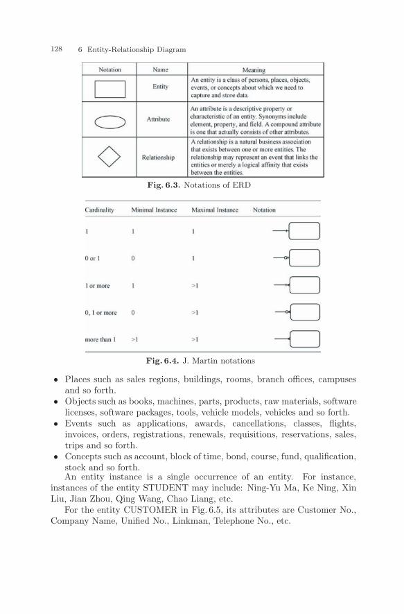
The three key concepts of ERD are Entity, Attribute and Relationship.Fig. 6.3 gives their notations and definitions.
J. Martin defined his notations for the entity relationship diagram whichis widely used. The round corner box is used as entity and the relationshipsare shown in Fig. 6.4.
6.2.1 Entity
An entity is a class of persons, places, objects, events, or concepts aboutwhich we need to capture and store data.• Persons such as agencies, contractors, customers, departments, divisions,
employees, instructors, students, suppliers and so forth.
128 6 Entity-Relationship Diagram
Fig. 6.3. Notations of ERD
Fig. 6.4. J. Martin notations
• Places such as sales regions, buildings, rooms, branch offices, campusesand so forth.
• Objects such as books, machines, parts, products, raw materials, softwarelicenses, software packages, tools, vehicle models, vehicles and so forth.
• Events such as applications, awards, cancellations, classes, flights,invoices, orders, registrations, renewals, requisitions, reservations, sales,trips and so forth.
• Concepts such as account, block of time, bond, course, fund, qualification,stock and so forth.An entity instance is a single occurrence of an entity. For instance,
instances of the entity STUDENT may include: Ning-Yu Ma, Ke Ning, XinLiu, Jian Zhou, Qing Wang, Chao Liang, etc.
For the entity CUSTOMER in Fig. 6.5, its attributes are Customer No.,Company Name, Unified No., Linkman, Telephone No., etc.

6.2 Syntax and Semantics of ERD 129
Fig. 6.5. An example of a person entity
6.2.2 Attribute
An attribute is a descriptive property or characteristic of an entity. Its syn-onyms include element, property, and field. A compound attribute is onethat actually consists of other attributes.
Attributes include following concepts, as shown in Fig. 6.6:
Fig. 6.6. Keys and relative subsetting criteria
• A key is an attribute, or a group of attributes, that assumes a uniquevalue for each entity instance.
• A group of attributes that uniquely identifies an instance of an entity iscalled a concatenated key.
• A candidate key is a “candidate to become the primary key” of instancesof an entity.
• A primary key is that candidate key that will most commonly be used touniquely identify a single entity instance.
• Any candidate key that is not selected to become the primary key is called

130 6 Entity-Relationship Diagram
an alternate key.• A subsetting criteria is an attribute (or concatenated attribute) whose
finite values divide all entity instances into useful subsets.For the entity CUSTOMER in Fig. 6.5, Customer No. is its primary key
and underlined.
6.2.3 Relationship
A relationship is a natural business association that exists between one ormore entities. The relationship may represent an event that links the entitiesor merely a logical affinity that exists between the entities.
A cardinality defines the minimum and maximum number of occurrencesof one entity that may be related to a single occurrence of the other entity.
Because all relationships are bidirectional, a cardinality must be definedin both directions for every relationship.
The degree of a relationship is the number of entities that participate inthe relationship.
Because of the different cardinalities, there are three kinds of relation-ships: one-to-one, one-to-many and many-to-many. Some examples aboutthe three kinds of relationships are presented in Fig. 6.7 with J. Martinnotations [4].
Fig. 6.7. An example of the three kinds of relationships
A one-to-one relationship means one instance of one entity relates to onecertain instance of another entity. For instance, normally, a husband hasa wife and a wife has a husband. No special wife may have more thanone husband, vice versa. It can be described, as shown in Fig. 6.8, in whichHUSBAND is an entity whose primary key is Husband Number and non-keyattribute is his Name, and WIFE is also an entity whose primary key is WifeNumber and non-key attribute is her Name.
A one-to-one relationship is easy to be mapped to base tables in a DBMSin which a foreign key can be used to embody such a relationship. For

6.2 Syntax and Semantics of ERD 131
Fig. 6.8. Couple relationship
instance, the primary key of the entity WIFE, Wife Number, is transferredto the entity HUSBAND as its foreign key, as shown in Fig. 6.8. Thus, form-ing one base table for each entity, one for HUSBAND and one for WIFE, asshown in Fig. 6.9, it is easy to find couple relationship based on Wife Number.In this example, H102 Ke Ning’s wife is W106 Hui Lu and W101 Da-FengXu’s husband is H105 Jian Zhou. In the table HUSBAND, Wife Number isa foreign key to relate the table WIFE.
Fig. 6.9. Base tables for couple relationship
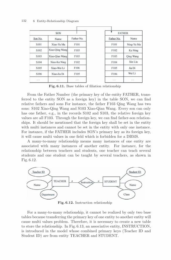
A one-to-many relationship means one instance of one entity relates to oneor more instances of another entity. For instance, in the filiation relationship,one son can only have one father, and one father can have one or more sons,as shown in Fig. 6.10. In the ERD, FATHER is an entity and Father Numberis its primary key. Another entity is SON with Son Number as its primarykey. The relationship between them is one-to-many. Add a foreign key tothe entity with multi instances can realize the relationship with base tables,as shown in Fig. 6.11.
Fig. 6.10. Filiation relationship
132 6 Entity-Relationship Diagram
Fig. 6.11. Base tables of filiation relationship
From the Father Number (the primary key of the entity FATHER, trans-ferred to the entity SON as a foreign key) in the table SON, we can findrelative fathers and sons For instance, the father F103 Qing Wang has twosons: S102 Xiao-Qing Wang and S103 Xiao-Qian Wang. Every son can onlyhas one father, e.g., in the records S102 and S103, the relative foreign keyvalues are all F103. Through the foreign key, we can find father-son relation-ships. It should be mentioned that the foreign key shall be set in the entitywith multi instances and cannot be set in the entity with only one instance.For instance, if the FATHER includes SON’s primary key as its foreign key,it will cause multi values in one field which is forbidden for a DBMS.
A many-to-many relationship means many instances of one entity areassociated with many instances of another entity. For instance, for therelationship between teachers and students, one teacher can teach severalstudents and one student can be taught by several teachers, as shown inFig. 6.12.
Fig. 6.12. Instruction relationship
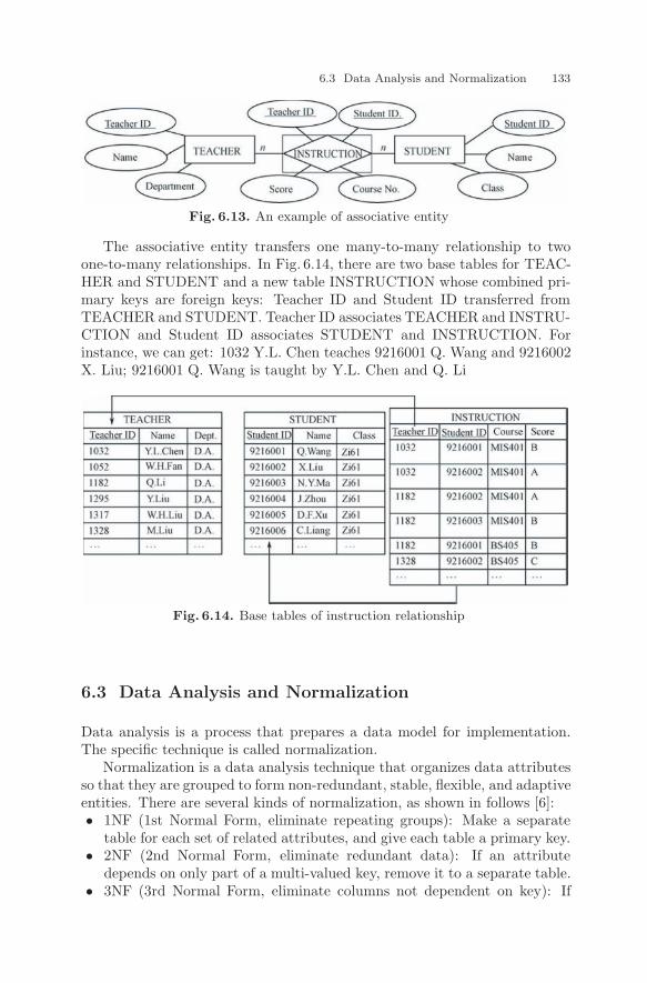
For a many-to-many relationship, it cannot be realized by only two basetables because transferring the primary key of one entity to another entity willcause multi values problem. Therefore, it is necessary to create a new tableto store the relationship. In Fig. 6.13, an associative entity, INSTRUCTION,is introduced in the model whose combined primary keys (Teacher ID andStudent ID) are from entity TEACHER and STUDENT.
6.3 Data Analysis and Normalization 133
Fig. 6.13. An example of associative entity
The associative entity transfers one many-to-many relationship to twoone-to-many relationships. In Fig. 6.14, there are two base tables for TEAC-HER and STUDENT and a new table INSTRUCTION whose combined pri-mary keys are foreign keys: Teacher ID and Student ID transferred fromTEACHER and STUDENT. Teacher ID associates TEACHER and INSTRU-CTION and Student ID associates STUDENT and INSTRUCTION. Forinstance, we can get: 1032 Y.L. Chen teaches 9216001 Q. Wang and 9216002X. Liu; 9216001 Q. Wang is taught by Y.L. Chen and Q. Li
Fig. 6.14. Base tables of instruction relationship
6.3 Data Analysis and Normalization
Data analysis is a process that prepares a data model for implementation.The specific technique is called normalization.
Normalization is a data analysis technique that organizes data attributesso that they are grouped to form non-redundant, stable, flexible, and adaptiveentities. There are several kinds of normalization, as shown in follows [6]:• 1NF (1st Normal Form, eliminate repeating groups): Make a separate
table for each set of related attributes, and give each table a primary key.• 2NF (2nd Normal Form, eliminate redundant data): If an attribute
depends on only part of a multi-valued key, remove it to a separate table.• 3NF (3rd Normal Form, eliminate columns not dependent on key): If
134 6 Entity-Relationship Diagram
attributes do not contribute to a description of the key, remove them toa separate table.
• BCNF (Boyce-Codd Normal Form): If there are non-trivial dependenciesbetween candidate key attributes, separate them out into distinct tables.
• 4NF (4th Normal Form, isolate independent multiple relationships): Notable may contain two or more one-to-many or many-to-many relation-ships that are not directly related. For example, if you can have twophone number values and two email address values, then you should nothave them in the same table.
• 5NF (5th Normal Form, isolate semantically related multiple relation-ships): There may be practical constraints on information that justifyseparating logically related many-to-many relationships.
• ONF (Optimal Normal Form): A model limited to only simple (elemental)facts, as expressed in Object Role Model notation.
• DKNF (Domain-Key Normal Form): A model free from all modificationanomalies.1NF, 2NF and 3NF are common requirements for data analysis.
6.3.1 1st Normal Form (1NF)
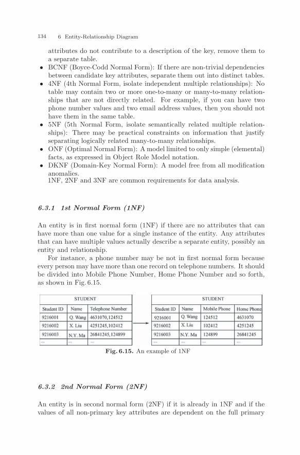
An entity is in first normal form (1NF) if there are no attributes that canhave more than one value for a single instance of the entity. Any attributesthat can have multiple values actually describe a separate entity, possibly anentity and relationship.
For instance, a phone number may be not in first normal form becauseevery person may have more than one record on telephone numbers. It shouldbe divided into Mobile Phone Number, Home Phone Number and so forth,as shown in Fig. 6.15.
Fig. 6.15. An example of 1NF
6.3.2 2nd Normal Form (2NF)
An entity is in second normal form (2NF) if it is already in 1NF and if thevalues of all non-primary key attributes are dependent on the full primary

6.3 Data Analysis and Normalization 135
key – not just part of it. Any non-key attributes that are dependent on onlypart of the primary key should be moved to any entities where that partialkey is actually the full key. This may require creating a new entity andrelationship for the model.
For instance, in Fig. 6.16, table TRADE has attributes: Order No., Cus-tomer No., Customer Phone No., Sum and Date. Order No. and CustomerNo. is the combined primary key. The table is in 1NF. Because CustomerPhone No. is functionally depended on Customer No., the table is not in2NF.
Fig. 6.16. Table not in 2NF
Fig. 6.17. Tables after 2NF
In order to solve the problem, it is necessary to divide the table TRADEinto two tables: TRADE and CUSTOMER as shown in Fig. 6.17. The newstructure is in 2NF and will not loss any information.
6.3.3 3rd Normal Form (3NF)
An entity is in third normal form (3NF) if it is already in 2NF and if thevalues of its non-primary key attributes are not dependent on any othernon-primary key attributes. Any non-key attributes that are dependent onother non-key attributes must be moved or deleted. Again, new entities andrelationships may have to be added to the data model.
For instance, in Fig. 6.18, for table STUDENT, Student Number is theprimary key. Its non-key attributes are Name, Teacher and Class. In thetable, Teacher is functionally dependent on Class, so it is necessary to divide

136 6 Entity-Relationship Diagram
the table into two tables as shown in Fig. 6.19. The modified tables are 3NFand will not loss any information.
Fig. 6.18. Table not in 3NF
Fig. 6.19. Tables after 3NF
6.4 Structured Approach and Modeling Case of ERD
The steps of data modeling and analysis by ERD include:• Collect original data for modeling task.• Identify entities and form an entity pool.• Identify attributes for every entity.• Identify keys from attributes of every entity.• Identify relationships between entities.• Develop the primary ERD.• Identify cardinality for every relationship.• Migrate keys based on relationships.• Refine the primary ERD by normalization.
For the database system design, there are three key deliverables relatedto three key phases:
(1) ERDAn ERD presents a logical design for a data base. the ERD includes
entities with relative attributes and relationships.(2) Base tableBase tables present their contents with attribute names, field names, data
types, formats, field sizes, remarks and so forth.(3) Foreign Key Diagram

6.4 Structured Approach and Modeling Case of ERD 137
A foreign key diagram presents keys relationships among tables. Arrowsare used to present the relationship between foreign keys and relative table’sprimary key.
Fig. 6.20 is the ERD for a course selection system. Table 6.1 –Table 6.5are base tables for every entity. Fig. 6.21 is the foreign key diagram.
Fig. 6.20. ERD of a course selection system
Table 6.1. Base table of STUDENTSTUDENT
AttributeName
FieldName
Type Format FieldSize
Rule and Illustration Remark
Student ID Sno char 99999999 8 PrimaryKey
StudentName
Sname char 20
Cell Phone Mphone char 9999-999-999 12Home Phone Hphone char (999)-9999-
999915 Including area code
Address Saddress char 50 Including doorplatecode
DepartmentNo.
Dno char 999 3 Department nameabbreviation
ForeignKey
Class SClass char 12
Table 6.2. Base table of TEACHERTEACHER
AttributeName
Field Name Type Format FieldSize
Rule and Illustration Remark
Teacher ID Tno char 9999 4 PrimaryKey
TeacherName
Tname char 20
Specialty Specialty char 80Phone No. Ttel char 9999 4 Including Ext-codeDepartmentNo.
Dno char 999 3 ForeignKey

138 6 Entity-Relationship Diagram
Table 6.3. Base table of SCORE
SCORE
Attribute
Name
Field
Name
Type Format Field Siza Rule and Illus-
tration
Remark
Score No. SCno char 99999999 8 Primary
Key
Course No. Cno char 999 3 Primary
Key
Teacher ID Tno char 9999 4 Primary
Key
Student ID Sno char 99999999 8 Primary
Key
Semester Semester char 999 3
Score Score number 100 is the full
mark and 60 is
pass
Table 6.4. Base table of DEPARTMENT
DEPARTMENT
Attribute
Name
Field Name Type Format Field
Size
Rule and Illustration Remark
Department
No.
Dno char 999 3 Primary
Key
Department
Name
Department
name
char 50
Department
Director
Ddirector char 4 Is Teacher ID Foreign
Key
Phone No. Dtel char 9999 4 Including Ext code
Table 6.5. Base table of COURSE
COURSE
Attribute
Name
Field Name Type Format Field
Size
Rule and Illustra-
tion
Remark
Course No. Con char 999 3 Primary
Key
Course Name Course
name
char 50
Credit Cnumber number
Required/
Selective
ReqEle Boolean 9 1 Y:Required
N:Selective
Department
No.
Dno char 999 3 Foreign
Key

References 139
Fig. 6.21. Foreign key relationship diagram
References
[1] Whitten J L, Bentley L D, Dittman K C. System Analysis and Design Meth-ods. McGraw-Hill Education, 2004.
[2] Chen P P. The Entity-Relationship Model – Toward a Unified View of Data.ACM Transactions on Database Systems, 1 (1): 9 – 36, 1976.
[3] KBSI. IEEE Std 1320. 2 – 1998: IEEE Standard for Conceptual ModelingLanguage Syntax and Semantics for IDEF1X. IEEE, 1998.
[4] Benjamin P C. etc. Information Integration for Concurrent Engineering(IICE) IDEF5 Method Report. KBSI Co., 1994.
[5] Codd E F. Further Normalization of the Data Base Relational Model. IBMResearch Report RJ909, 1971.
[6] datamodel. org. Rules of Data Normalization. www.datamodel.org, 2008.