realtime control-oriented modeling and disturbance
TRANSCRIPT

Realtime Control-oriented Modeling and Disturbance Parameterization for Smart and
Reliable Powder Bed Fusion Additive Manufacturing
X. Chen1, D. Wang, T. Jiang, and H. Xiao
Department of Mechanical Engineering, University of Connecticut, Storrs, CT, 06269, USA
Abstract
The vision of sustainable mass customization calls for additive manufacturing (AM) processes that
are resilient to process variations and interruptions. This work targets to pioneer a system-
theoretical approach towards such a smart and reliable AM. The approach is based on control-
oriented modeling of the process variations and on closed-loop model-based controls that facilitate
in-situ adjustment of the part quality. Specifically, one focused example is laser-aided powder bed
fusion. Building on the in-layer precision heating and solidification, together with layer-by-layer
iterations of the energy source, feedstock, and toolpath, we discuss mathematical abstractions of
process imperfections that will not only understand the intricate thermomechanical interactions
but are also tractable under realtime computation budgets. In particular, we develop and validate
a surrogate modeling of in-process disturbances induced by the periodic in- and cross-layer
thermomechanical interactions. This control-oriented disturbance modeling allows for the
adoption of high-performance control algorithms to advance AM quality in a closed loop, and we
show a first-instance study on the effect of repetitive controls in reducing melt-pool variations in
the periodic energy deposition.
1 Introduction
In contrast to conventional machining, where parts are made by cutting away unwanted
material, additive manufacturing (AM) – also called 3D printing – builds three-dimensional objects
of unprecedented complexity by progressively adding small amounts of material. Powder bed
fusion (PBF), in which new material is added to the part being fabricated by applying and
selectively melting a powdered feedstock, is a popular form of AM for fabricating complex
metallic or high-performance polymeric parts. Despite such capabilities and countless emerging
applications, limited reliability and reproducibility are hindering broader adoption of this
manufacturing technology. Under the current state of the art, unpredictable variations in parts arise
from different machines or even from the same machine on a different day [1]. It remains not well
understood how to systematically and predictably control the process for assured quality. The
absence of such knowledge challenges a broad range of applications that impact our everyday lives
(e.g., digital manufacturing of final products for jet engines [2], automobiles [3-4], oil and gas
industry [5], and medical implants [6]). This study aims to provide new knowledge critical to the
advancement of quality-assured PBF AM. The focus is on a system-theoretical understanding and
a control-oriented disturbance modeling of the key energy deposition in laser-based PBF.
1 Corresponding author. 191 Auditorium Rd U 3139, Storrs, CT, 06269-3139. [email protected].

The PBF process builds on precision heating and solidification in a short time scale,
together with convoluted layer-by-layer iterations that take hours or days to complete (Figure 1).
The physics of this non-contact energy deposition is a union of thermal balance, phase change, and
solid mechanics. Pre-process high-fidelity simulations [7-10] can map out an initial parameter
space, and post-process material analyses can reveal the internal quality of the built parts; however,
mitigation of various in-process disturbances and uncertainties ultimately hinges on realtime,
feedback-based controls. Such controls have remained a long-felt but not fully realized vista in
PBF, because a major disconnection exists between current architectures of online controls and
the modeling of the multi-scale complex process. Algorithms in the realm of high-fidelity
modeling are prohibitively expensive under a realtime computation budget: simulating just a few
layers of practical energy deposition can take hundreds of hours [11]. In the realm of control-
oriented PBF modeling, existing sparse attempts of lumped parameters have been limited to the
fusing of a single line. The modeling of layer-to-layer interactions and scanning patterns has not
been established yet. These complex dynamics, involving heat transfer from the already-solidified
materials, fundamentally impact part quality [12-13].
Figure 1: PBF AM: quality of part is tailored by layered energy deposition.
The objective of this paper is to step beyond current control-oriented modeling and fill the
critical gap pertaining to the lack of systematic disturbance models usable under a realtime
computation budget. The proposed approach is to integrate knowledge and experience from
precision mechatronics into related thermophysics, photonics, and laser optics in PBF. Tools from
this list have been key for reaching nanometer-scale control resolutions in layer-by-layer
manufacturing processes such as semiconductor manufacturing. We will create the surrogate
models from a multi-physics multi-scale model, by partitioning the task space based on first-
principle analysis, neglecting weak couplings in the energy balance equation, and linearization
around a quasi-stationary equilibrium. To increase the fidelity of the models, we will then add
disturbance dynamics to account for the neglected thermal interactions. Along the course of
developing the modeling framework, we also identified a highly structured temperature variation
rising from periodic scanning patterns germane to the 3D infill process. Such patterns make it
feasible to decouple an analytically tractable disturbance model from the complex heating-cooling
cycles. The result is that we will be able to form, for the first time to our best knowledge, a set of
computation-friendly process and disturbance models for feedback control of PBF, and understand
exactly how the structured disturbances impact the dynamic system. Taking advantage of the
parametric structures of these disturbance models, we propose a repetitive control algorithm for
reaching a quality-assured PBF AM.

The remainder of the paper is organized as follows. In Section 2, we elaborate the
fundamental thermodynamics in PBF and the simulation/experimentation platforms. The control-
oriented modeling of PBF is proposed in Section 3. Section 4 analyzes extended cross-layer
thermal interactions and applies repetitive control to compensate the periodic structured thermal
disturbances. Section 5 concludes this paper.
2 Fundamental thermodynamics, simulation and experimentation platforms
2.1 Review of PBF mechanism and relevant thermal physics
A typical object in PBF is built from many thousands of thin layers (tens to several
hundreds of microns thick). During the solidification of each layer, a high-power laser or electron
beam forms a microscopic melt pool that moves at several meters per second to selectively
sinter/melt the particle powders (Figure 2-c). After consolidation, the bed is lowered by the
thickness of a new thin layer. New powders are then spread over the current deposit to start the
next repetition (Figure 2-a).
Figure 2: Illustration of the PBF process.
The strong form of the governing nonlinear thermodynamics comprises radiation,
convection, conduction, and phase change (Figure 2-b). The central dynamic equation is a partial-
differential energy balance equation with intricate boundary conditions (Figure 2-d) and involves
a first-order derivative in time, second-order derivatives in three spatial coordinates, and a forcing
term that encapsulates the external heating rates. (The effect of the energy source can be considered
either in the forcing term [7] or as a boundary condition.) There are two distinct worlds of modeling
the multi-physical process. In the first, much larger world of numerical methods [8-10, 14], weak
forms of the governing equations are obtained by physics-based order reduction. Successful
approaches include: 1) removing or combining weak couplings such as surface convection and
radiation [7, 11]; 2) Gaussian modeling of the heat source [15]; 3) polynomial or static
approximation of the nonlinear parameter variations; and 4) assuming very localized or
numerically canceled latent heat from phase change. Finite element and difference methods are
then employed to numerically solve the models. In the second, very small world of control-oriented
modeling, the sparse attempts that exist use lumped parameter modeling. Low-order linearized
models have been proposed [16, 17] based on input-output system identification of a black-box
transfer function.
2.2 Simulation and experimentation platforms
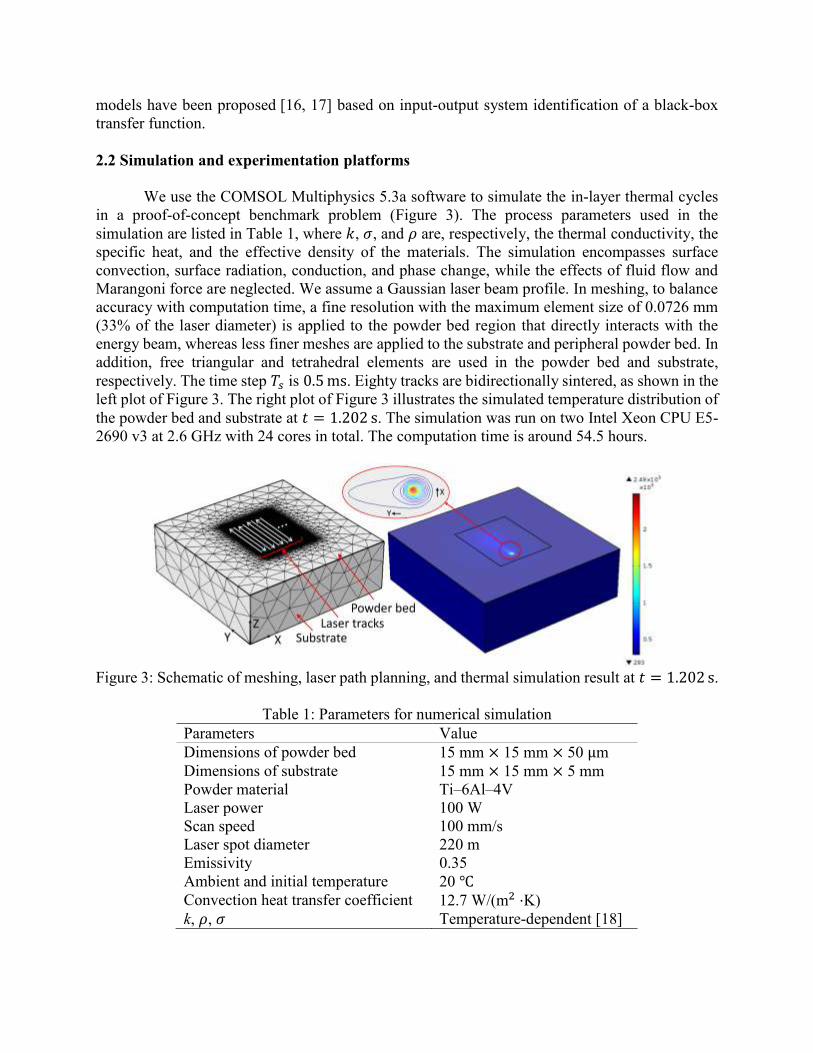
We use the COMSOL Multiphysics 5.3a software to simulate the in-layer thermal cycles
in a proof-of-concept benchmark problem (Figure 3). The process parameters used in the
simulation are listed in Table 1, where 𝑘, 𝜎, and 𝜌 are, respectively, the thermal conductivity, the
specific heat, and the effective density of the materials. The simulation encompasses surface
convection, surface radiation, conduction, and phase change, while the effects of fluid flow and
Marangoni force are neglected. We assume a Gaussian laser beam profile. In meshing, to balance
accuracy with computation time, a fine resolution with the maximum element size of 0.0726 mm
(33% of the laser diameter) is applied to the powder bed region that directly interacts with the
energy beam, whereas less finer meshes are applied to the substrate and peripheral powder bed. In
addition, free triangular and tetrahedral elements are used in the powder bed and substrate,
respectively. The time step 𝑇𝑠 is 0.5 ms. Eighty tracks are bidirectionally sintered, as shown in the
left plot of Figure 3. The right plot of Figure 3 illustrates the simulated temperature distribution of
the powder bed and substrate at 𝑡 = 1.202 s. The simulation was run on two Intel Xeon CPU E5-
2690 v3 at 2.6 GHz with 24 cores in total. The computation time is around 54.5 hours.
Figure 3: Schematic of meshing, laser path planning, and thermal simulation result at 𝑡 = 1.202 s.
Table 1: Parameters for numerical simulation
Parameters Value
Dimensions of powder bed 15 mm × 15 mm × 50 μm
Dimensions of substrate 15 mm × 15 mm × 5 mm
Powder material Ti–6Al–4V
Laser power 100 W
Scan speed 100 mm/s
Laser spot diameter 220 m
Emissivity 0.35
Ambient and initial temperature 20 ℃
Convection heat transfer coefficient 12.7 W/(m2 ⋅K)
k, 𝜌, 𝜎 Temperature-dependent [18]

The experimentation platform used in this paper is an in-house developed selective laser
sintering testbed (Figure 4). Laser scan experiments are conducted on this platform to investigate
the cross-layer thermal patterns in PBF. Figure 4 shows the setup for testing the cross-layer thermal
interactions. This sample part is directly attached to the build plate that are heated by multiple heat
resistors from underneath.
Figure 4: Experiment setup and sample part.
3 Control-oriented modeling of repetitive variations in PBF
Under the usual assumptions in high-fidelity modeling [7, 11], the dominant thermal
dynamics in the heat affected zone is described by the energy conservation equation:
𝜌𝜎𝜕𝑇
𝜕𝑡− [
𝜕
𝜕𝑥(𝑘
𝜕𝑇
𝜕𝑥) +
𝜕
𝜕𝑦(𝑘
𝜕𝑇
𝜕𝑦) +
𝜕
𝜕𝑧(𝑘
𝜕𝑇
𝜕𝑧)] − 𝑞(𝑡, 𝑥, 𝑦, 𝑧) = 0, (1)
where 𝑇 is the temperature of materials and 𝑞 is the nonlinear forcing term encapsulating the heat
source.
(1) Order-of-Magnitude Analysis of the Time Scales
For the thermal interactions on the surface layer, the basic mechanism between the energy
beam and powder material is a high-speed precision scanning that consists of: 1) single-stroke line
fusion; 2) a periodic raster scanning that completes the infill. In the limit of extremely thin and
shallow scan path, the heat flow is largely restricted in one direction. A valid approximation of
Equation 1 is then 𝜕𝑇/𝜕𝑡 − 𝑐2𝜕2𝑇/𝜕𝑝2 − 𝑞(𝑡, 𝑝) = 0, where 𝑝 is the direction of scanning and
𝑐2 = 𝑘/(𝜌𝜎). This is a coarse approximation; however, an order-of-magnitude analysis on the
simplified model suffices to reveal the time dependence of the thermal conditions. Meshing the
spatial domain with the step size 𝛿𝑝 and performing the second-order numerical approximation
𝜕2𝑇𝑖/𝜕𝑝2 ≈ (𝑇𝑖+1 − 2𝑇𝑖 + 𝑇𝑖−1)/𝛿𝑝2, we obtain a first-order ordinary differential equation with a
time constant 𝜏 = 𝜌𝜎𝛿𝑝2/(2𝑘). For the common polymeric powder Nylon 12, 𝑘/(𝜌𝜎) is on the
order of 10−7 m2/s. With 𝛿𝑝 being on the order of 200 microns (∼ the layer thickness), the time
constant is approximately 0.2 seconds. For metals such as Ti6Al4V, 𝜏 ≈ 0.005 seconds

(𝑘/(𝜌𝜎) ∼ 10−6m2/s, 𝛿𝑝 ∼100 μm). Thus, when the time to finish a stroke is longer than or in
the same order of magnitude of the discussed time constant, unneglectable heat will start
transferring to the adjacent lines and layers. With these distributions of time scales, it is hence
essential to systematically understand the in-layer dynamics, and the proposed model will cover
them with: 1) a continuous moving source model; 2) an in-layer heating-cooling disturbance
model.
(2) Single-stroke laser-material interaction
The proposed single-stroke model is based on analytics of the fundamental heat and fluid
flows during laser-material processing. We define the normalized heat flux as the input 𝐮(𝑡),
which is related to the reflectivity of the material ℛ, power of the heat source 𝑃, beam spot size
𝐴spot, and scan speed 𝑉𝑠, by 𝐮 = (1 − ℛ)𝑃/𝐴spot/𝑉𝑠. The proposed states 𝐱(𝑡) and output are the
important melt-pool characteristics including overall area and width. When the beam is scanned
very fast so that the boundaries of the surface layer are approximately adiabatic (zero temperature
gradient), both temperature and geometry of the melt pool have empirical low-order dynamics [16,
19-20].
We first transform the full-order model (Equation 1) into a quasi-stationary surrogate by
assuming constant material properties and introducing a new coordinate system that is attached to
the heat source [21]. Within this transformed coordinate (𝜉, 𝑦, 𝑧) with 𝜉 = 𝑥 − 𝑢𝑥𝑡 , ideally a
consistent melt pool is formed, along with a quasi-stationary state of the temperature field 𝑇 =𝑓𝑇(𝑇𝑜, 𝜉, 𝑦, 𝑧, 𝑢𝑥, 𝑞, 𝜎, 𝜌, 𝑘), where 𝑢𝑥 and 𝑞 are, respectively, the scanning speed and the input
heat flux in the (𝜉, 𝑦, 𝑧) coordinate. For instance, given a point heat source, this mapping has the
analytic Rosenthal solutions [21], and the temperature distribution at the quasi-stationary state is
𝑇 − 𝑇0 =𝑞
2𝜋𝑘𝑟e
−𝑢𝑥(𝑟+𝜉)
2𝑐2 , (2)
where 𝑟 = √𝜉2 + 𝑦2 + 𝑧2. The geometric profile of the melt pool is subsequently defined. We
then have a nonlinear static mapping in the form of 𝐱𝑠𝑠 = 𝑓𝑥(𝑇𝑜 , 𝐮𝑠𝑠).
At the edge of the melt pool, 𝑇 equals the melting point Tm. Thus, for a point laser source,
by letting 𝜉 = 𝑧 = 0 and 𝑦 = 𝑤/2 in Equation (2), where 𝑤 is the width of the melt pool, we have
𝑇𝑚 − 𝑇0 =𝑞
𝜋𝑘𝑤e
−𝑢𝑥𝑤4𝑐2 . (3)
Using the above quasi-stationary state as an equilibrium point and perturbing the full-order
model around the equilibrium, we identify a second-order linearized plant based on input-output
system identification:
𝑃(𝑠) =1.301 × 10⁵𝑠 + 1.409 × 10⁸
𝑠2 + 5752𝑠 + 4.377 × 10⁶. (4)

As shown in Figure 5, response of the identified surrogate model closely matches with the
full-order simulation result. Here, we use the laser power as the input and the peak temperature
(i.e., maximum melt pool temperature) as the output. The latter is closely related to the melt-pool
geometry. To be more specific, a higher peak temperature results in larger temperature gradient on
the melt pool surface and subsequently leads to larger Marangoni convection between the center
and the edge of the melt pool surface [22, 23]. More melted powders are then drawn into the melt
pool, leading to a wider melt pool width. To get a uniform part quality, the melt pool width and
hence peak temperature are desired to be kept constant during the beam scanning [20].
Figure 5: Step responses of the identified plant model and simulation data.
Building on top of this baseline single-stroke operation model, we will establish next a
modeling of the thermal disturbances in raster scanning.
(3) Control-oriented modeling of thermal disturbances
Inconsistencies exist in the temperature field after the repetitive scanning and fusion of
materials [24]. Such cross-scan interactions enter as disturbances to the quasi-stationary state in
Subsection 3-(2) and create different melt-pool properties. This is particularly harmful to materials
with a high thermal conductivity or when a long scan distance is desired. Our central observation
is that a highly repetitive temperature variation occurs due to periodic scanning patterns in the
infill process. Hence it is feasible to decouple an analytically tractable disturbance model from the
complex heating-cooling cycles. Early clues from experimental investigations in materials science
and engineering support this observation [25], but the effect has not been systematically explored
in the domain of dynamic systems and model-based controls.
Figure 6: Proposed modeling of the cross-scan interactions.
To mathematically formalize the concept, it is important to recognize that materials around
the melt pool are heated and cooled as functions of space and time (Figure 6-a, b). The already

fused track #𝑛 − 𝑖 (𝑖 ≤ 1) will create a heating-cooling cycle to the powder materials on track #𝑛
(Figure 6-c). For instance, when 𝑖 = 3, this pre-heating on track #𝑛 is governed by conduction
from track #𝑛 − 3 starting at the “just-sintered” state (determined from the Rosenthal solution if
the energy input is from a point source). The governing 3D transient heat transfer dictates that the
temperature will be inhomogeneous along the sintering direction (the 𝜉 axis), but has the form of
𝑓𝑛−3(𝜉, 𝑢𝑥, 𝑞, 𝑡). Extending the analysis to other tracks, we can model the collective effect of all
fused tracks as the superposition of the individual heating-cooling cycles: ∑ 𝑓𝑛−𝑖𝑛−1𝑖=1 (𝜉, 𝑢𝑥 , 𝑞, 𝑡 +
𝜏𝑖)1(𝑡 − 𝜏𝑖), where 1(𝑡) is the Heaviside step function and 𝜏𝑖 is the time interval between the
sintering of tracks #𝑛 − 𝑖 and #𝑛.
For track #𝑛 + 2, analogous procedures yield the same pattern of temperature distribution.
The equivalent disturbance effect is thus proposed to satisfy a repetitive or quasi-repetitive model:
𝑑(𝑡) = 𝛼𝑑(𝑡 − 𝜏) + 𝑤𝑜(𝑡) , where 𝛼 ≈ 1 and 𝑤𝑜(𝑡) accounts for the effect of other less-
structured in-process disturbances. Since tracks far away from the heat source contribute
insignificantly to the cumulative heating (Figure 6-b), a steady state or a slowly varying mode
forms when the number of tracks is large. In other words, 𝛼 converges to 1. The repetitive portion
of the disturbance can then be modeled as the impulse response of 𝐺𝑟(𝑠) = 𝐵𝑑(𝑠)/(1 − 𝑒−𝑠𝜏),
where 𝐵𝑑(𝑠) is a polynomial of 𝑠 with no roots on the imaginary axis. The period of the signal 𝜏
is a function of the scanning pattern.
Although we have focused on the in-layer heat transfer, the above analysis applies also to
the layer-wise thermodynamics, and repetitive thermal interactions exist also across layers. For
instance, in Figure 7, at the start of a new layer, the peak temperatures at points A and C will be
higher than that of point B because previously solidified layers beneath A and C have accumulated
more thermal energy that will conduct to the top surface. The supporting cross-layer experiments
are provided in Section 4.
Figure 7: Illustrative diagram of cross-layer sintering.
4 Results and analysis
4.1 In-layer thermal interaction and repetitive control for peak temperature regulation
Figure 8 shows the simulation results validating the in-layer thermal interactions. We
observe that after a short transient, the average peak temperature reaches a steady state as a result
of balanced heat influx and diffusion. After reaching the steady state, the peak temperature
fluctuates around the average value (2356.2 K). Besides, the start of each laser scanning track
(except the first track) has larger peak temperatures than the rest of the track. This is because in
raster scanning (Figure 3), when the energy beam approaches the end of one track, the large latent
heat does not have enough time to dissipate out before the next track starts. These increased

temperatures at the beginning of each track form a periodic disturbance with a repetitive spectrum
in the frequency domain (top plot of Figure 9). The fundamental frequency 𝑓0 of the disturbance
is defined by the period of the scanning motion 𝑡0, that is, 𝑓0 = 1/𝑡0 = 𝑢𝑥/𝐿, where 𝐿 is the track
length. In this example, 𝑓0 = 100/5 = 20 Hz, and frequency spikes at {𝑛𝑓0} (𝑛 ∈ ℤ+) appear in
the fast Fourier transform of the disturbance. It is noteworthy that besides the raster scan that was
used as a unit problem in this study, other scanning patterns yield similar repetitive disturbance
patterns (see, e.g., experimental results in [27]). As such, automatic control algorithms [26] can be
applied to attenuate those undesired repetitive spectra of peak temperature, as will be illustrated
next.
Figure 8: Peak temperature variation due to in-layer scanning patterns.
To get a uniform in-layer temperature distribution during the scanning of a single track in
the repetitive beam motion, we apply a well-tuned baseline PID controller and a plug-in repetitive
controller [28] by using the surrogate model as the plant and the generated temperature variation
from the multi-scale multi-physics simulation as the add-on disturbance. Here, the PID control
provides a basic closed-loop performance with a bandwidth of 639 Hz, while the repetitive control
enables high-performance compensation of the periodic disturbances. It is observed that PID
control alone fails to properly attenuate the thermal disturbance: over 80 Kelvin degrees of
variation show up in the controlled peak temperature (dashed line in Figure 10), and large harmonic
modes in the frequency spectrum match with the aforementioned calculations (top plot of Figure
9). After adding the proposed repetitive control on top of the PID algorithm, we observe significant
attenuations of the periodic disturbances in both the time domain (solid line in Figure 10) and the
frequency domain (bottom plot in Figure 9). In particular, the peak temperature was controlled to
be nearly constant.

Figure 9: Spectrum of closed-loop temperature variations during in-layer raster scanning.
Figure 10: Simulated closed-loop peak temperature of the melt pool under raster scanning and
the proposed repetitive control.
4.2 Cross-layer thermal interaction: repetitive variations of melt pool width
Similar to the in-layer case where previously sintered tracks generate thermal disturbances
to the new track, the heating-cooling cycles of previously sintered layers also create disturbances
to the temperature profile of the surface layer. As a result, the temperature distribution across the
powder bed is the lumped output of both in-layer and cross-layer heat transfer dynamics (Figure
7). The cross-layer thermal disturbance is particularly harmful for parts with abrupt geometric
changes, such as those with overhang structures, and we identify next such effects from a control-
oriented analysis based on experimentation results in the in-house selective laser sintering testbed
(Figure 4).
A pre-fabricated aluminum part (Figure 4) is buried in Nylon 12 powders with a few thin
layers of powders spread on top of the flat surface of the part. At the stage of pre-heating, since
aluminum has a higher thermal conductivity than Nylon 12, the temperature of the powders on top
of the part surface is significantly higher than that of the powders outside (left plot of Figure 11).
We generate a raster scanning (right plot of Figure 11) with a 2.8Watt 445nm laser diode that has
the proper energy density to fuse the powder materials. The pattern has a much larger width than
the aluminum part underneath. This configuration imitates the sintering process of parts with
overhang structures, and the aluminum part corresponds to previously fused layers. The powder
bed thermal profile is recorded by a FLIR A325sc infrared camera.

Figure 11: Illustration of cross-layer disturbance: high-temperature fused material in previous
layers create periodic thermal disturbance to the energy deposition on the top layer. (The area
around the powder bed in (a) is caused by camera error due to inconsistent surface conditions.)
Figure 12: Temporal evolution of melt pool width.
We observe significant repetitive variations of the melt pool width (evaluated by pixel
numbers in the video frames) from the temporal evolution in Figure 12. Since the initial powder
temperature inside the boundary of the aluminum part is much larger than that outside, every time
the laser scans through the thin powder on top of the aluminum part, a larger melt pool width is
generated (Tracks 4-7 in Figure 12). Correspondingly, multiple frequency spikes show up in the
frequency-domain spectrum of the melt pool width (Figure 13). In particular, the peak frequencies
0.44 Hz and 0.88 Hz correspond to the single-stroke scan period. Our ongoing research is targeting
at high-performance control solutions to attenuate these cross-layer thermal disturbances that are
closely related to geometric features and thermal-material interactions.

Figure 13: Melt pool width spectrum.
(The low-frequency spike corresponds to the steady-state value of the melt pool width)
5 Conclusions
This paper provides a new control-oriented disturbance modeling and a system-theoretical
understanding of the energy deposition in powder bed fusion (PBF) additive manufacturing.
Starting from the intricate multi-scale PBF thermal physics, we investigated and modelled two in-
process disturbances induced by in- and cross-layer thermal-material interactions. Along the
course of developing the modeling framework, we identified highly structured temperature
variations rising from periodic beam-scanning patterns and part geometry. The resulting
disturbance parameterization provides a new design space for advanced control algorithms to
improve the quality of PBF-manufactured parts, and we presented a plug-in repetitive controller
design for substantially better control of the melt-pool profile.
References
[1] Spears, Thomas G., and Scott A. Gold. "In-process sensing in selective laser melting
(SLM) additive manufacturing." Integrating Materials and Manufacturing Innovation 5.1
(2016): 2.
[2] DiCintio, Richard Martin, and Patrick Benedict Melton. "System for cooling a fuel injector
extending into a combustion gas flow field and method for manufacture." U.S. Patent No.
9,551,490. 24 Jan. 2017.
[3] Jones, Carl P., et al. "Additive Manufacturing a Liquid Hydrogen Rocket Engine." (2016).
Available at https://ntrs.nasa.gov/search.jsp?R=20160006986
[4] Clark, Corey. "University of Nottingham’s FLAC project makes fuel efficient 3d printed
car components." (2017). Available at https://3dprintingindustry.com/news/university-
nottinghams-flac-project-makes-fuel-efficient-3d-printed-car-components-103775/
[5] Grunewald, Scott J. "3d printing brings new opportunities and new challenges to the oil &
gas industry." (2016). Available at https://3dprint.com/118892/3d-printing-oil-gas-
industry/
[6] Grunewald, Scott J. "Stryker’s spine division to debut 3d printed tritanium posterior lumbar
cage spinal implant." (2017). Available at https://3dprint.com/132281/stryker-tritanium-
implant/
[7] King, W., et al. "Overview of modelling and simulation of metal powder bed fusion process
at Lawrence Livermore National Laboratory." Materials Science and Technology 31.8
(2015): 957-968.
[8] Weissman, E. M., and M. B. Hsu. "A Finite Element Model of Multi-Layered Laser
Sintered Parts." 1991 International Solid Freeform Fabrication Symposium. 1991.
[9] Smith, Jacob, et al. "Linking process, structure, property, and performance for metal-based
additive manufacturing: computational approaches with experimental support."
Computational Mechanics 57.4 (2016): 583-610.
[10] Foroozmehr, Ali, Mohsen Badrossamay, and Ehsan Foroozmehr. "Finite element
simulation of selective laser melting process considering optical penetration depth of laser
in powder bed." Materials & Design 89 (2016): 255-263.
[11] Zeng, Kai, Deepankar Pal, and Brent Stucker. "A review of thermal analysis methods in
laser sintering and selective laser melting." Proceedings of Solid Freeform Fabrication
Symposium Austin, TX. 2012.
[12] Carter, Luke N., et al. "The influence of the laser scan strategy on grain structure and
cracking behaviour in SLM powder-bed fabricated nickel superalloy." Journal of Alloys
and Compounds 615 (2014): 338-347.
[13] Mertens, Raya, et al. "Optimization of scan strategies in selective laser melting of
aluminum parts with downfacing areas." Journal of Manufacturing Science and
Engineering 136.6 (2014): 061012.
[14] Childs, T. H. C., et al. "Simulation and experimental verification of crystalline polymer
and direct metal selective laser sintering." Proc. SFF Symp., Austin. 2000.
[15] Hodge, N. E., R. M. Ferencz, and J. M. Solberg. "Implementation of a thermomechanical
model for the simulation of selective laser melting." Computational Mechanics 54.1
(2014): 33-51.
[16] Craeghs, Tom, et al. "Feedback control of Layerwise Laser Melting using optical sensors."
Physics Procedia 5 (2010): 505-514.
[17] Mireles, Jorge, et al. "Closed-loop automatic feedback control in electron beam melting."
The International Journal of Advanced Manufacturing Technology 78.5-8 (2015): 1193-
1199.
[18] Neira-Arce, Alderson. "Thermal Modeling and Simulation of Electron Beam Melting for
Rapid Prototyping on Ti6Al4V Alloys." (2012).
[19] Cao, Xiaoqing, and Beshah Ayalew. "Control-oriented MIMO modeling of laser-aided
powder deposition processes." American Control Conference (ACC), 2015. IEEE, 2015.
[20] Hofman, J. T., et al. "A camera based feedback control strategy for the laser cladding
process." Journal of Materials Processing Technology 212.11 (2012): 2455-2462.
[21] Kannatey-Asibu Jr, Elijah. Principles of laser materials processing. Vol. 4. John Wiley &
Sons, 2009.
[22] Lee, Yousub, and Dave F. Farson. "Simulation of transport phenomena and melt pool shape
for multiple layer additive manufacturing." Journal of Laser Applications 28.1 (2016):
012006.
[23] Matthews, Manyalibo J., et al. "Denudation of metal powder layers in laser powder bed
fusion processes." Acta Materialia 114 (2016): 33-42.
[24] Wegner, A., and G. Witt. "Process monitoring in laser sintering using thermal imaging."
SFF Symposium, Austin, Texas, USA. 2011.

[25] Islam, M., et al. "Temperature profile and imaging analysis of laser additive manufacturing
of stainless steel." Physics Procedia 41 (2013): 835-842.
[26] Wang, D., and X. Chen. "A multirate fractional-order repetitive control for laser-based
additive manufacturing." Control Engineering Practice 77 (2018): 41-51.
[27] Dunbar, Alexander J., et al. "Comparisons of laser powder bed fusion additive
manufacturing builds through experimental in situ distortion and temperature
measurements." Additive Manufacturing 15 (2017): 57-65.
[28] Chen, Xu, and Masayoshi Tomizuka. "New repetitive control with improved steady-state
performance and accelerated transient." IEEE Transactions on Control Systems
Technology 22.2 (2014): 664-675.