part a, section 2 - nordsonemanuals.nordson.com/adhesives/english_manuals/a20301.pdf · part a,...
TRANSCRIPT

� 2001 Nordson CorporationAll rights reserved
41-3000VIssued 6/01
A2EN−03−[3V−1−AXXV]−1
Part A, Section 2
Description
This section covers the following unit configurations.
Model 3100V
Voltage All
Pump Piston (E, F, or G)
Manifold All
Control Vista Standard (V)

DescriptionA 2-0
� 2001Nordson CorporationAll rights reserved
41-3000VIssued 6/01
A2EN−03−[3V−1−AXXV]−1

Description A 2-1
� 2001 Nordson CorporationAll rights reserved
41-3000VIssued 6/01
A2EN−03−[3V−1−AXXV]−1
Section A 2Description
Series 3100V applicators may be used only to melt and pump hot meltmaterial. They are not intended for use with polyurethane-reactive hotmelt material. Use the applicators only as described in this manual.
This manual describes how to install, operate, and service a Series3100V applicator. It also explains how the applicator works with othermajor components of a hot melt system.
This section of the manual describes the key parts of the applicator andhow they work. It includes the following topics:
� Functional Description
� Major Components
� Control System
� Specifications
� Dimensions
� Explanation of Configuration Code
For information about any options or accessories you may have orderedwith your unit, refer to the Options section.
1. Intended Use
2. Overview
DescriptionA 2-2
� 2001Nordson CorporationAll rights reserved
41-3000VIssued 6/01
A2EN−03−[3V−1−AXXV]−1
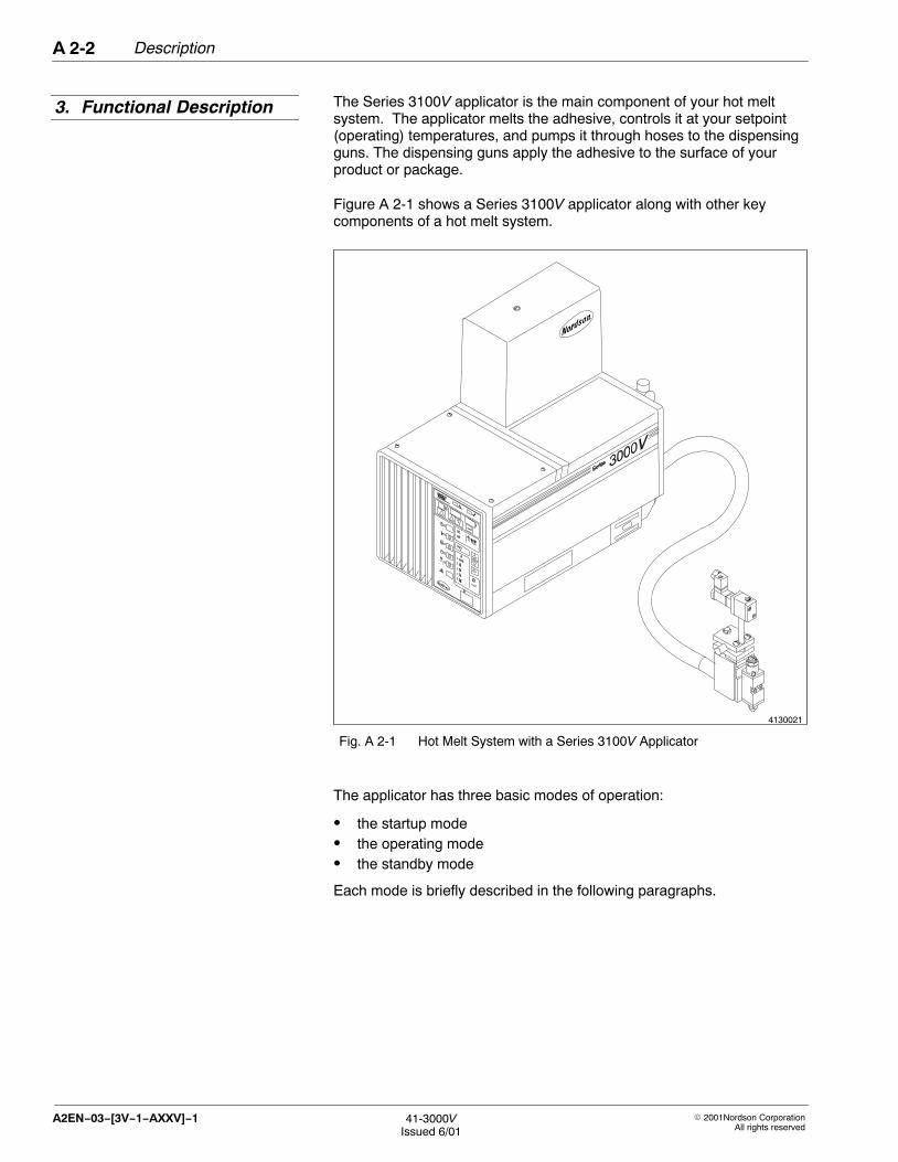
The Series 3100V applicator is the main component of your hot meltsystem. The applicator melts the adhesive, controls it at your setpoint(operating) temperatures, and pumps it through hoses to the dispensingguns. The dispensing guns apply the adhesive to the surface of yourproduct or package.
Figure A 2-1 shows a Series 3100V applicator along with other keycomponents of a hot melt system.
4130021
Fig. A 2-1 Hot Melt System with a Series 3100V Applicator
The applicator has three basic modes of operation:
� the startup mode� the operating mode� the standby mode
Each mode is briefly described in the following paragraphs.
3. Functional Description

Description A 2-3
� 2001 Nordson CorporationAll rights reserved
41-3000VIssued 6/01
A2EN−03−[3V−1−AXXV]−1
During a sequential startup, when the clock timer or an operator turns thesystem on, the tank and hoses begin to heat first. After the temperaturesof the tank and hoses are all within 19.5 °C (35 °F) of their setpointtemperatures, the guns begin to heat. When the tank, hoses, and gunsare within 3 °C (5 °F) of their setpoint temperatures, a time delay begins.The time delay, which you can adjust, provides additional time for thematerial in the tank to melt. At the end of the time delay, the greenREADY light turns on, indicating that the system is ready for operation.You can program the system so the pump starts automatically, eitherwhen the READY light turns on or when the tank reaches thetemperature you have specified. Or you can program the system so thepump must be started manually.
The capability to heat all zones simultaneously is also available.
When you trigger a gun, the pump draws in the melted adhesive andsends it through a manifold, a filter, and a hose to the gun, which thenapplies the adhesive to the product or package surface. Figure A 2-2shows the components of a typical hot melt system and the path thatmelted adhesive follows when being pumped through the system. Inmost systems, an air-operated automatic gun is used to apply the meltedadhesive. An electrically driven gun or a handgun (shown in dotted linesin Figure A 2-2) may also be used to apply adhesive.
When you place the applicator in the standby mode, the control systemdisables the pump and reduces the temperature of all heating zones tothe standby temperature setpoints you have selected. You can use thestandby mode to keep the adhesive warm when normal operation mustbe interrupted for a while. The lower temperature reduces char formationand conserves energy.
Startup Mode
Operating Mode
Standby Mode

DescriptionA 2-4
� 2001Nordson CorporationAll rights reserved
41-3000VIssued 6/01
A2EN−03−[3V−1−AXXV]−1
4103990
ÇÇ
2
ÇÇÇÇÇÇÇÇÇÇÇÇÇÇÇÇÇÇÇÇÇÇÇÇÇÇÇÇÇÇÇÇÇÇÇÇÇÇÇÇÇÇÇÇÇÇÇÇ
3
4
5
6
7
8
9
1113
12
10
1
Fig. A 2-2 Adhesive Flow Path of a Typical Hot Melt System (standard filter shown)
1. Air piston2. Air cylinder3. Pump4. Air pressure regulator5. Hydraulic plunger
6. Tank7. Pressure relief valve8. Manifold9. Manifold filter
10. Drain valve
11. Hose12. Air-operated gun13. Handgun and hose

Description A 2-5
� 2001 Nordson CorporationAll rights reserved
41-3000VIssued 6/01
A2EN−03−[3V−1−AXXV]−1
The major components of the applicator are briefly described on thefollowing pages.
1
2
3
5
4
4130023
Fig. A 2-3 Major Components of a Typical Series 3100V Applicator
1. Pump2. Tank3. Air pressure regulator
4. Manifold components5. Operator panel
4. Major Components

DescriptionA 2-6
� 2001Nordson CorporationAll rights reserved
41-3000VIssued 6/01
A2EN−03−[3V−1−AXXV]−1
The tank melts the adhesive and holds it until it is pumped to thedispensing guns. With its aluminum construction, cast-in heaters, andintegral melting fins, the tank is designed for efficient heat transfer. Astrainer in the tank prevents unmelted adhesive from blocking the pumpinlet when you fill the tank. It also prevents pieces of cardboard andother small objects from entering the pump.
The standard tank is PTFE-coated for easy cleaning. A non-coated tankis available on some units.
Refer to Specifications in this section for the tank storage capacity andother key information about the tank.
4130761
1
2
34
Fig. A 2-4 Key Parts of the Tank
1. Tank casting2. Strainer
3. Melting fins4. Heater connectors
Tank

Description A 2-7
� 2001 Nordson CorporationAll rights reserved
41-3000VIssued 6/01
A2EN−03−[3V−1−AXXV]−1
The pump transfers the melted adhesive from the tank to the dispensingguns. With its dual-acting design, the piston pump delivers adhesive tothe product or package surface on both the upstroke and the downstroke.
The pump has three main parts:
� an air motor� a hydraulic section� an actuator
Refer to Specifications in this section for the pump delivery rate and otherkey information about the pump.
4130650
1
2
3
Fig. A 2-5 Key Parts of the Pump
1. Air motor2. Hydraulic section3. Actuator
Pump

DescriptionA 2-8
� 2001Nordson CorporationAll rights reserved
41-3000VIssued 6/01
A2EN−03−[3V−1−AXXV]−1
The manifold directs the flow of adhesive from the pump to the filter andfrom the filter to the hoses and guns.
The manifold has four main parts:
� a manifold block with hose connectors� a manifold filter� a drain valve� a pressure relief valve
4130653
4
1
23
Fig. A 2-6 Key Parts of the Manifold
1. Manifold block with hoseconnectors
2. Drain valve
3. Manifold filter4. Pressure relief valve
Manifold Block and Hose Connectors
The manifold block has a 45-degree face for either horizontal or verticalhose routing. A maximum of four hoses can be connected to themanifold.
Manifold Filter
The manifold filter traps any char or foreign material, keeping it frombeing pumped to the hoses and guns. The applicator is shipped with a0.15-mm (0.006-in.) filter screen. Other screen sizes are available.
Manifold

4130666
1
23
Description A 2-9
� 2001 Nordson CorporationAll rights reserved
41-3000VIssued 6/01
A2EN−03−[3V−1−AXXV]−1
Drain Valve
The drain valve allows you to drain the tank and manifold or to flush charand debris from the filter screen. Operators can perform the filter flushingprocedure without removing the filter from the manifold.
Pressure Relief Valve
The pressure relief valve prevents system hydraulic pressure fromexceeding 10,400 kPa (1500 psi). At this pressure, the valve opens andreturns adhesive to the tank.
The air pressure regulator allows you to adjust the system air pressure,which controls the hydraulic pressure.
The regulator assembly has three main parts:
� a regulator� a filter� a gauge
The gauge indicates the air pressure and the filter removes contaminantsfrom the plant air supply.
Fig. A 2-7 Key Parts of the AirPressure Regulator
1. Regulator2. Filter3. Air pressure gauge
The operator panel provides the controls and indicators you need toprogram, operate, and monitor your hot melt system. The key functionsof the operator panel are described in the next part of this section,Control System.
Air Pressure Regulator
Operator Panel

DescriptionA 2-10
� 2001Nordson CorporationAll rights reserved
41-3000VIssued 6/01
A2EN−03−[3V−1−AXXV]−1
The control system regulates all temperature settings and controls howthe unit functions. The operator panel allows you to program the systemto meet changing needs:
� Heated zones are controlled individually, giving you more flexibility insetting up your system.
� With the seven-day clock feature, you can tailor operations for a weekat a time, with different schedules for each day of the week.
The control system is designed so that a brownout or power failure willnot cause a loss of your programmed settings.
The operator panel provides the controls, indicators, and messagesneeded to operate the system. It is divided into four functional areas:
� System Status� Displays� System Setup� System Controls
4103925
1
2
3
4
Fig. A 2-8 Operator Panel
1. System Status area2. Displays area
3. System Setup area4. System Controls area
5. Control System
Features of the Operator Panel

Description A 2-11
� 2001 Nordson CorporationAll rights reserved
41-3000VIssued 6/01
A2EN−03−[3V−1−AXXV]−1
The System Status area of the operator panel gives you a quicksummary of the status of your system. The FAULT and READY lights letyou know if the system is prepared for operation.
4103926
1 2
Fig. A 2-9 System Status Area
1. FAULT light 2. READY light
FAULT Light
The red FAULT light indicates different types of fault conditions. Refer toTable A 2-1.
Table A 2-1 System Notification of FAULT Conditions
FAULT Light Status (see Note) System Condition
FAULT light turns on and stayson.
A heater zone is overtemperature.
FAULT light flashes for twominutes, then stays on.
FAULT light flashes continuously.
A resistance temperature detector(RTD) in any zone is open orshorted.
A heater zone is out of band,either high or low.
A heater zone is more than19.5 �C (35 �F) under thesetpoint temperature.
NOTE: When the FAULT light turns on and stays on, the systemremoves heater power for all zones. When the FAULT light flashes,heater power stays on.
READY Light
The green READY light turns on when the following conditions exist:
� All zones are within +/− 3 °C (+/− 5 °F) of the setpoint temperatures.� The system-ready time delay has elapsed.� No faults exist.
System Status Area

DescriptionA 2-12
� 2001Nordson CorporationAll rights reserved
41-3000VIssued 6/01
A2EN−03−[3V−1−AXXV]−1
The Displays area of the operator panel gives you detailed informationabout the status of your system. When you are running the system, itshows the status of each heating zone. When you are customizing thesystem, it shows your current system setup.
4130011
1 2 3
46 5
Fig. A 2-10 Displays Area
1. Selector display2. Multipurpose display3. Actual temperature display
4. Enter key5. Up and Down keys6. Up key
Selector Display and Up Key
The Selector display allows you to access information about the status ofyour system during operation and system setup. The display
� shows the selected zone number when used with TEMPERATUREand when scanning
� shows the day when used with CLOCK
� shows the feature number when used with SYSTEM SETTINGS
The Up key, which is located below the Selector display, changes thevalue of a setting.
Displays Area

Description A 2-13
� 2001 Nordson CorporationAll rights reserved
41-3000VIssued 6/01
A2EN−03−[3V−1−AXXV]−1
Multipurpose Display and Keys
During normal operation, the Multipurpose display shows the setpointtemperature for a selected zone. This allows you to compare the actualtemperature of the displayed zone with its targeted temperature.
Actual Temperature Display
The Actual Temperature display shows the actual temperature of theheated zone. When the scan mode is enabled, each zone is displayed insequence. When the scan mode is disabled, only the temperature for theselected zone is displayed.
Enter Key
The Enter key saves the number shown in the Multipurpose display.

4103928
3
1
4
5
2
DescriptionA 2-14
� 2001Nordson CorporationAll rights reserved
41-3000VIssued 6/01
A2EN−03−[3V−1−AXXV]−1
The System Setup area of the operator panel allows you to customize thesystem to your needs. From this area you can control
� the temperature at which each zone operates (TEMPERATURE)� how the unit operates (SYSTEM SETTINGS)� when the system operates (CLOCK)
To customize system controls, use the keys in the System Setup area inconjunction with the keys in the Displays area.
Move Up and Move Down Keys
The Move Up and Move Down keys select features within the SystemSetup area, allowing you to tailor the system to your needs. You canselect the following features using the Move Up and Move Down keys:
� SETPOINT temperature� STANDBY temperature� SYSTEM SETTINGS� SET TIME� ENTER STANDBY� EXIT STANDBY� HEATERS ON� HEATERS OFF
Fig. A 2-11 System Setup Area
1. Move Up and Move Down keys2. Move Right key3. TEMPERATURE area4. SYSTEM SETTINGS area5. CLOCK area
Move Right Key
The Move Right key selects features within the System Setup area,allowing you to tailor the system to your needs. You can select thefollowing features using the Move Right key:
� INTERNAL zone� HOSE zone� GUN zone� INTERVAL 1� INTERVAL 2
System Setup Area

Description A 2-15
� 2001 Nordson CorporationAll rights reserved
41-3000VIssued 6/01
A2EN−03−[3V−1−AXXV]−1
TEMPERATURE Area
From the TEMPERATURE area you can program the setpoint andstandby temperatures for three types of heated zones: internal, hose, orgun.
When used in the TEMPERATURE area,
� The Move Up and Move Down keys select SETPOINT or STANDBY.
� The Move Right key selects the zone type (internal, hose, or gun) forprogramming temperatures (standby or setpoint).
SYSTEM SETTINGS Area
From the SYSTEM SETTINGS area you can customize or check thesettings of the following system features:
� password enable� system-ready time delay� overtemperature setpoint� Celsius or Fahrenheit units� global temperature bands� individual temperature bands� sequential startup or simultaneous startup� display heater proportioning� warning or power notification� ready or pump notification� auto-energize pump� auto-energize heaters� time with heaters on� fault log display� auto-energize pump temperature setting
CLOCK Area
From the CLOCK area you can program the system to turn heaters on oroff or to place the system in standby or operating mode at a time that youselect. The clock stores two sets of times, referred to as intervals. Eachinterval stores four settings as shown in Table A 2-2.
Table A 2-2 Interval Settings
INTERVAL 1 INTERVAL 2
Standby Settings Enter
Exit
Enter
Exit
Heater Settings On
Off
On
Off

4103929
1
2
3
4
5
6 7
DescriptionA 2-16
� 2001Nordson CorporationAll rights reserved
41-3000VIssued 6/01
A2EN−03−[3V−1−AXXV]−1
The System Controls area of the operator panel allows you to controlbasic system operations and override programmed controls. The lights inthis area tell you whether a feature is on or off. Using the keys andswitches in this area, you can
� Monitor the status of a particular zone, or scan each zone to check itsstatus.
� Take the system into or out of standby.
� Turn the heaters on or off.
� Turn the clock feature on or off. (This is useful when you do not wantthe system to start automatically.)
� Turn the pump on or off.
� Run a system test to determine whether a fault that the system hasdetected was corrected.
� Turn main power to the applicator on or off.
Fig. A 2-12 System Controls Area
1. MONITOR/SCAN key and light2. STANDBY key and light3. HEATERS key and light4. CLOCK key and light5. PUMP key and light6. CLEAR FAULTS key7. POWER switch
MONITOR/SCAN Key and Light
Pressing the MONITOR/SCAN key places the system in the monitor orscan mode. In the scan mode,
� The system scans each heated zone, displaying each zone’stemperature in sequence.
� If the system-ready time delay feature is active, the system shows thenumber of minutes remaining until the system is ready for operation.
� The MONITOR/SCAN light turns on and stays on.
System Controls Area

Description A 2-17
� 2001 Nordson CorporationAll rights reserved
41-3000VIssued 6/01
A2EN−03−[3V−1−AXXV]−1
In the monitor mode,
� The system displays the temperature of only the zone currentlyselected.
� If the system-ready time delay feature is active and is currentlyselected for monitoring, the system shows the number of minutesremaining until the system is ready for operation.
� The MONITOR/SCAN light stays on.
STANDBY Key and Light
Pressing the STANDBY key when the HEATERS light is on takes thesystem into or out of the standby mode. When the standby feature isactive,
� The STANDBY light turns on.
� The READY light turns off.
� The pump turns off.
� Temperatures on all zones drop until the temperature of each zonereaches the preselected standby temperature.
� The HEATERS light remains on.
If the HEATERS light is not on, you cannot place the system in thestandby mode.
When the standby feature is disabled,
� The STANDBY light turns off.
� The heaters turn on and all zones begin heating.
� If the auto-energize pump feature is active, the pump turns on eitherwhen the system reaches the ready condition or when the tankreaches the temperature you have specified.
� After all zones have reached their preselected setpoint temperature,the READY light turns on.

DescriptionA 2-18
� 2001Nordson CorporationAll rights reserved
41-3000VIssued 6/01
A2EN−03−[3V−1−AXXV]−1
HEATERS Key and Light
Pressing the HEATERS key turns power to the heaters on and off. Theheaters must be turned on for the unit to operate.
The HEATERS light turns on when this feature is active.
NOTE: If the system is set for auto-energize heaters, the heaters areautomatically enabled and the HEATERS light turns on when thePOWER switch is turned on.
CLOCK Key and Light
Pressing the CLOCK key turns the seven-day clock on and off. Whenthe clock is on, the system is controlled by the settings for ENTERSTANDBY, EXIT STANDBY, HEATERS ON, and HEATERS OFF.
The CLOCK light turns on when this feature is active.
NOTE: If the clock feature is enabled when the POWER switch is turnedoff, it will automatically be enabled when the switch is turned back on.The CLOCK light will turn on to show that the clock feature is enabled.
PUMP Key and Light
Pressing the PUMP key turns the pump on and off. The PUMP lightturns on when this feature is active.
NOTE: If the system is set for auto-energize pump, the pump turns oneither when the READY light turns on or when the tank reaches thetemperature you have specified.
CLEAR FAULTS Key
Pressing the CLEAR FAULTS key runs a system test. The test lasts fiveseconds and verifies that the problem causing a system fault wascorrected. If the problem was corrected, the FAULT light in the SystemStatus area of the operator panel will turn off once the test is completed.If the problem was not corrected, the FAULT light will stay on.
POWER Switch
Pressing the POWER switch turns power to the applicator on or off.
Description A 2-19
� 2001 Nordson CorporationAll rights reserved
41-3000VIssued 6/01
A2EN−03−[3V−1−AXXV]−1
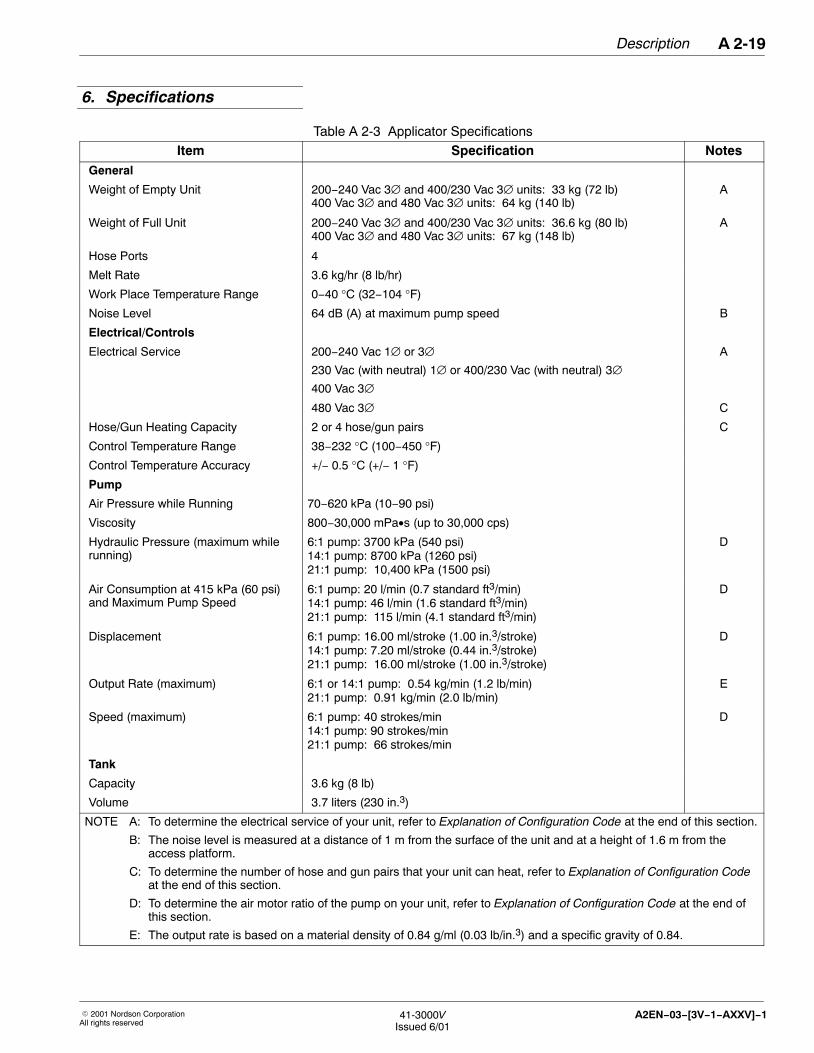
Table A 2-3 Applicator Specifications
Item Specification NotesGeneral
Weight of Empty Unit 200−240 Vac 3∅ and 400/230 Vac 3∅ units: 33 kg (72 lb)400 Vac 3∅ and 480 Vac 3∅ units: 64 kg (140 lb)
A
Weight of Full Unit 200−240 Vac 3∅ and 400/230 Vac 3∅ units: 36.6 kg (80 lb)400 Vac 3∅ and 480 Vac 3∅ units: 67 kg (148 lb)
A
Hose Ports 4
Melt Rate 3.6 kg/hr (8 lb/hr)
Work Place Temperature Range 0−40 °C (32−104 °F)
Noise Level 64 dB (A) at maximum pump speed B
Electrical/Controls
Electrical Service 200−240 Vac 1∅ or 3∅230 Vac (with neutral) 1∅ or 400/230 Vac (with neutral) 3∅400 Vac 3∅
A
480 Vac 3∅ C
Hose/Gun Heating Capacity 2 or 4 hose/gun pairs C
Control Temperature Range 38−232 °C (100−450 °F)
Control Temperature Accuracy +/− 0.5 °C (+/− 1 °F)
Pump
Air Pressure while Running 70−620 kPa (10−90 psi)
Viscosity 800−30,000 mPa•s (up to 30,000 cps)
Hydraulic Pressure (maximum whilerunning)
6:1 pump: 3700 kPa (540 psi)14:1 pump: 8700 kPa (1260 psi)21:1 pump: 10,400 kPa (1500 psi)
D
Air Consumption at 415 kPa (60 psi)and Maximum Pump Speed
6:1 pump: 20 l/min (0.7 standard ft3/min)14:1 pump: 46 l/min (1.6 standard ft3/min)21:1 pump: 115 l/min (4.1 standard ft3/min)
D
Displacement 6:1 pump: 16.00 ml/stroke (1.00 in.3/stroke)14:1 pump: 7.20 ml/stroke (0.44 in.3/stroke)21:1 pump: 16.00 ml/stroke (1.00 in.3/stroke)
D
Output Rate (maximum) 6:1 or 14:1 pump: 0.54 kg/min (1.2 lb/min)21:1 pump: 0.91 kg/min (2.0 lb/min)
E
Speed (maximum) 6:1 pump: 40 strokes/min14:1 pump: 90 strokes/min21:1 pump: 66 strokes/min
D
Tank
Capacity 3.6 kg (8 lb)
Volume 3.7 liters (230 in.3)
NOTE A: To determine the electrical service of your unit, refer to Explanation of Configuration Code at the end of this section.
B: The noise level is measured at a distance of 1 m from the surface of the unit and at a height of 1.6 m from theaccess platform.
C: To determine the number of hose and gun pairs that your unit can heat, refer to Explanation of Configuration Codeat the end of this section.
D: To determine the air motor ratio of the pump on your unit, refer to Explanation of Configuration Code at the end ofthis section.
E: The output rate is based on a material density of 0.84 g/ml (0.03 lb/in.3) and a specific gravity of 0.84.
6. Specifications

DescriptionA 2-20
� 2001Nordson CorporationAll rights reserved
41-3000VIssued 6/01
A2EN−03−[3V−1−AXXV]−1
4130848A
B
C
D
E
F1H
I
J
LM
G
K
N
AF2
F3F4F5
Fig. A 2-13 References for Applicator Dimensions and Clearances
Table A 2-4 Series 3100V Applicator Dimensions in Millimeters (Inches)Dimension mm (in.) Note Dimension mm (in.) Note Dimension mm (in.) Note
A 207 (8.16) 1 F1 381 (15.00) 6 K —
B 298 (11.75) 2 G 343 (13.50) L 62 (2.24) 7
C 38 (1.50) 3 H 249 (9.80) M 110 (4.32)
D 237 (9.33) 4 I 322 (12.69) N 165 (6.50) 8
E 519 (20.42) 5 J 559 (22.00)
NOTE 1: Clearance needed to remove filter.
2. Clearance needed to open control panel.
3. Clearance needed to remove electrical enclosure cover.
4. Clearance needed to remove pump cover.
5. 400 Vac 3∅ units = 595 (23.42). 480 Vac 3∅ units = 774 (30.47)
6. F2 = 432 (17.00), F3 = 457 (18.00), F4 = 584 (23.00), and F5 = 635 (25.00). 400 Vac 3∅ units = F3. 480 Vac 3∅units can be installed to fit footprints F1 through F5.
7. 480 Vac 3∅ units = 64 (2.50).
8. Size of tank opening = 140 mm x 125 mm (5.50 in. x 4.91 in.).
7. Dimensions

Description A 2-21
� 2001 Nordson CorporationAll rights reserved
41-3000VIssued 6/01
A2EN−03−[3V−1−AXXV]−1
To determine the features, options, and specifications your unit has,check the unit number (configuration code) printed on your shipping orderor on your unit. To find the code on your unit, look at the identificationplate located above the hose ports (see Figure A 2-14).
Once you have located the configuration code, refer to the following codedescriptions and example to determine the specific features and optionsof your unit.
4130667
123456
Fig. A 2-14 Location of Unit Number (Configuration Code)
8. Explanation ofConfiguration Code

DescriptionA 2-22
� 2001Nordson CorporationAll rights reserved
41-3000VIssued 6/01
A2EN−03−[3V−1−AXXV]−1
To determine the features and options specific to your unit, match thecode in each code position (Boxes 1−11) to the codes in the followingchart. The chart provides a description for each code. For moreinformation, see the example following the chart.
Model Voltage Pump/Drive
Manifold/Filter
VistaControls
ElectricalControl
Capacity
LanguageTags
Options
— /
1 2 3 4 5 6 7 8-11
Box� 1 Model Code
Series 3100V 3100VSeries 3400V 3400VSeries 3500V 3500VSeries 3700V 3700VSeries 3830V 3830VSeries 3860V 3860VSeries 3890V 3890VSeries 3930V 3930VSeries 3960V 3960V
Box� 2 Voltage Code
200-240 Vac 1∅ or 3∅ 1230 Vac (with neutral) 1∅, or 400/230 Vac (withneutral) 3∅
2
400 Vac 3∅ 3480 Vac 3∅ 4
Box� 3 Pump/Drive Code
6:1 piston pump G14:1 piston pump E21:1 piston pump F1/3 hp, 240 Vac drive gear pump L1/3 hp, 200 Vac drive gear pump K
Box� 4 Manifold/Filter Code
Non-circulating 4-port manifold with standard filter ANon-circulating 6-port manifold with standard filter BNon-circulating 6-port manifold with reverse-flush filter CNon-circulating 4-port manifold with standard filter andpressure control valve
J
Externally circulating 2-port manifold with circulationcontrol valve and standard filter
S
Externally circulating 2-port manifold with circulationcontrol valve and reverse-flush filter
T
Code Descriptions

Description A 2-23
� 2001 Nordson CorporationAll rights reserved
41-3000VIssued 6/01
A2EN−03−[3V−1−AXXV]−1
Model Voltage Pump/Drive
Manifold/Filter
VistaControls
ElectricalControl
Capacity
LanguageTags
Options
— /
1 2 3 4 5 6 7 8-11
Box� 5 Vista Controls Code
Vista control (standard) VVista pattern control (PC)
Vista temperature control (TC)
P
T
Box� 6 Electrical Control Capacity Code
2 hose/gun pairs 24 hose/gun pairs 46 hose/gun pairs 6
Box� 7 Language Tags Code
English/German DEnglish/French FEnglish/Japanese N
Box� 8-11 Options Code
Low-level indicator AInput/output board (standard) GInput/output board with hose/gun disable (enhanced) HInput/output board for TC controller JCE certification R

DescriptionA 2-24
� 2001Nordson CorporationAll rights reserved
41-3000VIssued 6/01
A2EN−03−[3V−1−AXXV]−1
The following example shows how the code 3400V-2EAV4D/AR can beused to determine the features and options of the unit.
Model Voltage Pump/Drive
Manifold/Filter
VistaControls
ElectricalControl
Capacity
LanguageTags
Options
3400V — 2 E A V 4 D / A R
1 2 3 4 5 6 7 8-11
Table A 2-5 Explanation of Example Configuration Code
Box Description Note
1 Series 3400V
2 230 Vac (with neutral) 1∅ service or 400/230 Vac (with neutral) 3∅ service A
3 14:1 piston pump
4 Non-circulating 4-port manifold with a standard filter
5 Standard Vista control system
6 Electrical capacity for heating 4 hose/gun pairs
7 Unit tags in English and German
8 Low-level indicator included as an option
9 CE certification included as an option
NOTE A: All units are shipped ready for three-phase operation but include a voltage plug (and a wiring harnesson some units) that allows you to quickly convert from three-phase operation to single-phase operation.Refer to Preparing the Unit for Single-Phase Operation in the Installation section.
Example