series 2300 sp pump - nordsonemanuals.nordson.com/adhesives/english_manuals/108719.pdf · nordson...
TRANSCRIPT
NORDSON CORPORATION � Duluth, Georgiawww.nordson.com
Series 2300 SP PumpInstallation and Maintenance Instructions
Part 108 719D

� 2001 Nordson CorporationAll rights reserved
108 719DIssued 5/01
41-2300-IS-20
Nordson Corporation welcomes requests for information, comments and inquiries about its products. Generalinformation about Nordson can be found on the Internet using the following address: http://www.nordson.com.
Address all correspondence to:
Nordson CorporationAttn: Customer Service11475 Lakefield Drive
Duluth, GA 30097
Notice
This is a Nordson Corporation publication which is protected by copyright. Original copyright February 2001. No part of this document may be photocopied, reproduced, or translated to another language without the prior written
consent of Nordson Corporation. The information contained in this publication is subject to change without notice.
Trademarks
AccuJet, AquaGuard, Asymtek, Automove, Autotech, Blue Box, CF, CanWorks, Century, Clean Coat, CleanSleeve,CleanSpray, Compumelt, Control Coat, Cross-Cut, Cyclo-Kinetic, Dispensejet, DispenseMate, Durafiber, Durasystem,Easy Coat, Easymove Plus, Econo-Coat, EPREG, ETI, Excel 2000, Flex-O-Coat, FlexiCoat, Flexi-Spray, Flow Sentry,
Fluidmove, Fluidshooter, FoamMelt, FoamMix, Helix, Horizon, Hose Mole, Hot Shot, Hot Stitch, Isocoil, Isocore, Iso-Flo, JR,KB30, Little Squirt, Magnastatic, MEG, Meltex, MicroSet, Millenium, Mini Squirt, Moist-Cure, Mountaingate, MultiScan,
Nordson, OmniScan, Opticoat, Package of Values, PluraFoam, Porous Coat, PowderGrid, Powderware, Pro-Flo, ProLink,Pro-Meter, Pro-Stream, PRX, RBX, Ready Cost, Rhino, S. design stylized, Saturn, SC5, SCF, Select Charge, Select Coat,Select Cure, Shur-Lok, Slautterback, Smart-Coat, Spray Squirt, Spraymelt, Super Squirt, Sure-Bond, Sure Coat, System
Sentry, Tela-Therm, Trends, Tribomatic, UniScan, UpTime, Veritec, Versa-Coat, Versa-Screen, Versa-Spray, Watermark, andWhen you expect more. are registered trademarks − ® − of Nordson Corporation.
ATS, Auto-Flo, AutoScan, BetterBook, Chameleon, CanNeck, Check Mate, CPX, Control Weave, Controlled Fiberization,EasyClean, Ebraid, Eclipse, Equi=Bead, Fillmaster, Gluie, Ink-Dot, Maxima, MicroFin, Minimeter, Multifil, OptiMix,
Pattern View, PluraMix, Primarc, Prism, Process Sentry, PurTech, Pulse Spray, Seal Sentry, Select Series, Sensomatic,Shaftshield, Spectral, Spectrum, Sure Brand, Swirl Coat, Vista, Walcom, and 2 Rings (Design)
are trademarks −� − of Nordson Corporation.
Loctite is a registered trademark of Loctite Corporation.
Parker Lubricant is a registered trademark of Parker Seal.
Never Seez is a registered trademark of Bostik Corporation.
Viton is a registered trademark of DuPont Dow Elastomers.

Table of Contents i
� 2001 Nordson CorporationAll rights reserved
108 719DIssued 5/01
41-2300-IS-20
Table of Contents
1. Introduction 1. . . . . . . . . . . . . . . . . . . . . . . . . . . . . . . . . . . . . . . . . . . . . . . . .
2. Overview of the Hydraulic System 2. . . . . . . . . . . . . . . . . . . . . . . . . . . . .
3. Troubleshooting Tables 3. . . . . . . . . . . . . . . . . . . . . . . . . . . . . . . . . . . . . .
Adhesive Application Defective 3. . . . . . . . . . . . . . . . . . . . . . . . . . . . .
Pump Not Working 7. . . . . . . . . . . . . . . . . . . . . . . . . . . . . . . . . . . . . . . .
Troubleshooting Test Procedures 8. . . . . . . . . . . . . . . . . . . . . . . . . . .
Relieving System Hydraulic Pressure 9. . . . . . . . . . . . . . . . . . . . . . . .
Manifold Blockage Check 9. . . . . . . . . . . . . . . . . . . . . . . . . . . . . . . .
Pump Siphon Ball and Seat Check 10. . . . . . . . . . . . . . . . . . . . . . .
Actuator Check 10. . . . . . . . . . . . . . . . . . . . . . . . . . . . . . . . . . . . . . . .
Pump Solenoid Valve Check 11. . . . . . . . . . . . . . . . . . . . . . . . . . . .
Testing Solenoid Voltage 11. . . . . . . . . . . . . . . . . . . . . . . . . . . . . . .
Pump Air Section Check 12. . . . . . . . . . . . . . . . . . . . . . . . . . . . . . . .
4. Pump Repair Procedures 13. . . . . . . . . . . . . . . . . . . . . . . . . . . . . . . . . . .
Servicing the Pump 13. . . . . . . . . . . . . . . . . . . . . . . . . . . . . . . . . . . . . .
Preparation for Pump Removal 13. . . . . . . . . . . . . . . . . . . . . . . . . .
Pump Removal 14. . . . . . . . . . . . . . . . . . . . . . . . . . . . . . . . . . . . . . . .
Replacing the Air Valve 14. . . . . . . . . . . . . . . . . . . . . . . . . . . . . . . . . . .
Actuator and Air Cylinder Assembly Removal 14. . . . . . . . . . . . .
Magnet Assembly Removal 15. . . . . . . . . . . . . . . . . . . . . . . . . . . . .
Valve Spool and Sleeve Removal 16. . . . . . . . . . . . . . . . . . . . . . . .
Valve Spool and Sleeve Installation 18. . . . . . . . . . . . . . . . . . . . . .
Actuator and Air Cylinder Assembly Installation 19. . . . . . . . . . . .
Series 2300 SP Piston PumpInstallation and MaintenanceInstructions

Table of Contentsii
� 2001 Nordson CorporationAll rights reserved
108 719DIssued 5/01
41-2300-IS-20
Replacing the Piston Cups 19. . . . . . . . . . . . . . . . . . . . . . . . . . . . . . . .
Replacing the Shifter Fork 21. . . . . . . . . . . . . . . . . . . . . . . . . . . . . . . .
Cleaning or Repairing the Pump Body 22. . . . . . . . . . . . . . . . . . . . . .
Piston Components Removal 23. . . . . . . . . . . . . . . . . . . . . . . . . . .
Siphon Ball and Pressure Ball Components Removal 24. . . . . .
Cleaning Pump Componenets 25. . . . . . . . . . . . . . . . . . . . . . . . . . .
Siphon Ball and Pressure Ball Components Installation 26. . . . .
Pump Components Installation 26. . . . . . . . . . . . . . . . . . . . . . . . . .
Pump Installation 28. . . . . . . . . . . . . . . . . . . . . . . . . . . . . . . . . . . . . .
System Restoration 28. . . . . . . . . . . . . . . . . . . . . . . . . . . . . . . . . . . .
5. Series 2300 SP Pump Parts List 29. . . . . . . . . . . . . . . . . . . . . . . . . . . . .
Series 2300 Service Kits 29. . . . . . . . . . . . . . . . . . . . . . . . . . . . . . . . . .
Series 2300 Piston Pump Parts List 29. . . . . . . . . . . . . . . . . . . . . . . .
Air Pressure Regulator Parts List 32. . . . . . . . . . . . . . . . . . . . . . . . . .
Series 2300 SP Piston PumpInstallation and MaintenanceInstructions (contd)

Series 2300 SP Pump 1
� 2001 Nordson CorporationAll rights reserved
108 719DIssued 5/01
41-2300-IS-20
Series 2300 SP PumpInstallation and Maintenance Instructions
WARNING: Allow only qualified personnel to perform thefollowing tasks. Follow the safety instructions in this documentand all other related documentation.
CAUTION: For the most reliable operation of the pump, installan air filter (5 micron particulate filter or better) as close aspossible to the applicator air pressure regulator. Refer toRegulator/Filter Assembly Parts List in this document for a list offilters to meet this requirement.
This installation and maintenance document covers troubleshootingprocedures for adhesive application and pump operation problems for theSeries 2300 SP pump. It also provides test procedures, repairprocedures, and pump assembly and component parts lists. If furtherassistance is needed, call your Nordson representative.
1. Introduction

Series 2300 SP Pump2
� 2001 Nordson CorporationAll rights reserved
108 719DIssued 5/01
41-2300-IS-20
Two major assemblies make up the hydraulic system: an air-drivenpiston pump and a manifold. The pump assembly includes a hydraulicsection, an air motor, and an actuator. The manifold assembly, which isindirectly heated by the tank, includes an aluminum manifold with hoseports, a filter assembly, a drain valve, and a pressure relief valve.
4131138A
1
2
3
4
Fig. 1 Key Parts of the Hydraulic System(shown with a typical tank and manifold)
1. Air motor2. Pump hydraulic section
3. Manifold4. Actuator
2. Overview of theHydraulic System

Series 2300 SP Pump 3
� 2001 Nordson CorporationAll rights reserved
108 719DIssued 5/01
41-2300-IS-20
These troubleshooting tables describe the kinds of adhesive applicationand pump-operation problems you may encounter and provide correctiveactions for handling those problems. When necessary, the tables refer tomore detailed diagnostic procedures. Refer to the appropriatetroubleshooting table for the type of problem you are experiencing:
� Adhesive Application Defective� Pump Not Working
Problem Possible Cause Corrective Action
1. Little or no adhesive output Applicator not at operatingtemperature
Wait for the time delay to expire andthe READY light to turn on.
Adhesive level too low Maintain at least 50% of the tank’sholding capacity.
Adhesive too cold Check the tank, hose, and guntemperature setpoints and adjustthem as necessary.
Clogged manifold filter Clean the manifold filter.
Blockage in manifold Check for blockage.
Cold hose-to-applicator orhose-to-gun joints
Insulate the joints.
Guns not operating properly Refer to the gun manual totroubleshoot gun problems.
Manifold heat exchanger (if applicable) blocked
Check manifold heat exchanger forblockage. Clean if necessary.
2. Wavy beads Adhesive too cold Check the tank, hose, and guntemperature setpoints and adjust asnecessary.
Ambient temperature below freezingor guns subject to draft
Protect the applicator and guns fromfreezing temperature conditions anddrafts.
Nozzles too far from product Position the guns so the nozzles areno more than 13 mm (0.5 in.) fromthe product.
Continued on next page
3. Troubleshooting Tables
Adhesive Application Defective

Series 2300 SP Pump4
� 2001 Nordson CorporationAll rights reserved
108 719DIssued 5/01
41-2300-IS-20
Problem Possible Cause Corrective Action
3. Excessive adhesive atbeginning of bead
Hose and gun temperature setpointsnot properly balanced (for example,hose temperature too low and guntemperature too high)
Check the tank, hose, and guntemperature setpoints and adjustthem as necessary.
Nozzles too far from product Position the guns so the nozzles areno more than 13 mm (0.5 in.) fromthe product.
Filter partially clogged (manifoldfilter, inline filter, etc.)
Clean the manifold filter or filters.
4. Adhesive stringing Nozzle too far from product Position the guns so the nozzles areno more than 13 mm (0.5 in.) fromthe product.
Adhesive too viscous Increase the hose or gun temperaturesetpoint or change to a compatiblelower-viscosity adhesive.
Adhesive too cold Check the tank, hose, and guntemperature setpoints and adjustthem as necessary.
Adhesive too old Do not exceed the recommended potlife of the adhesive.
5. Bead lays on product inconcentric circles
Adhesive too cold Check the tank, hose, and guntemperature setpoints and adjustthem as necessary.
Adhesive too viscous Change to a compatiblelower-viscosity adhesive.
6. Adhesive bouncing orsplashing from product
Nozzle orifice too small forapplication, resulting in need for toomuch hydraulic pressure
Change to a nozzle with a largerorifice and decrease hydraulicpressure.
Adhesive too hot Check the tank, hose, and guntemperature setpoints and adjustthem as necessary.
Adhesive not viscous enough Change to a compatiblehigher-viscosity adhesive.
Continued on next page
Adhesive ApplicationDefective (contd)

Series 2300 SP Pump 5
� 2001 Nordson CorporationAll rights reserved
108 719DIssued 5/01
41-2300-IS-20
Problem Corrective ActionPossible Cause
7. Adhesive not penetratingproduct
Adhesive too cold Check the tank, hose, and guntemperature setpoints and adjustthem as necessary.
Special coating on product Increase the temperature setpointsslightly or change adhesives.
Not enough adhesive being applied Change to a higher-flow nozzle,increase operating temperaturesetpoints slightly, or increasehydraulic pressure.
Adhesive too viscous Change to a compatiblelower-viscosity adhesive.
8. Gun spitting intermittently,causing erratic beadplacement
Adhesive level too low (pumpingesting air)
Maintain at least 50% of the tank’sholding capacity.
Depending on the viscosity of theadhesive, if it (usually pellets) heatsup rapidly the layer directly abovethe heated adhesive partially heatsup to form a bridge over thepremelter grid. This prevents therest of the adhesive from meltingand being transferred from premelterto the hopper.
Change to a compatiblelower-viscosity adhesive, or to anadhesive that is less likely to bridge,or raise the tank operatingtemperature setpoint to reduce theviscosity.
Product wet Preheat the product.
9. Adhesive gelling Changing to an adhesiveincompatible with the previousadhesive without first cleaning thesystem
Clean the system.
Adhesive heated for too long, oroverheated
Clean the system. Do not exceed the recommendedadhesive pot life, or Decrease the operating temperaturesetpoints.
10. Adhesive leaking from gun Guns not shutting off properly Refer to the gun manual totroubleshoot gun problems.
Continued on next page

Series 2300 SP Pump6
� 2001 Nordson CorporationAll rights reserved
108 719DIssued 5/01
41-2300-IS-20
Problem Possible Cause Corrective Action
11. Cartons popping open (goodadhesive penetration, butadhesive bond separates
Adhesive not cooling fast enough Decrease hydraulic pressure todecrease the bead size. Decrease the operating temperaturesetpoints slightly. Reduce the linespeed through the compressionsection. Increase the length of thecompression section. Cool theproduct. Use a stitched bead pattern.
Adhesive open time too long Change to an adhesive with a shorteropen time.
Adhesive deposit shearing Check for twisting or other adversemovement during the compressionsection.
12. Cartons popping open (pooradhesive transfer andpenetration on marriedproduct)
Adhesive cooling too fast Increase the hydraulic pressure toincrease the bead size. Increase theoperating temperature setpointsslightly. Decrease the distancebetween the nozzles and the product.Decrease the distance between beadapplication and bead compression.Heat the product. Use a higher-flownozzle. Avoid stitched bead patterns.Protect the gun or bead from cold air.
13. Adhesive fuming or smoking Adhesive in tank too hot Check the tank operating temperaturesetpoint and adjust it as necessary.
Unstable adhesive Keep the lid closed when theapplicator is operating. Change to amore stable adhesive.
14. Adhesive charring in tank Adhesive in tank too hot Check the tank operating temperaturesetpoint and adjust it as necessary.
Tank overheating Check the setpoint temperature. Thesetpoint temperature must be 38 �C(100 �F) or above for the zone toheat.
Adhesive level too low Maintain at least 50% of the tank’sholding capacity.
Adhesive oxidizing in tank Keep the lid closed when theapplicator is operating. Change to amore stable adhesive.
Adhesive ApplicationDefective (contd)
Series 2300 SP Pump 7
� 2001 Nordson CorporationAll rights reserved
108 719DIssued 5/01
41-2300-IS-20
Problem Possible Cause Corrective Action
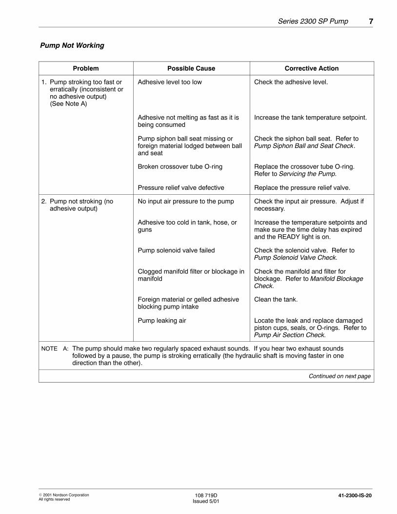
1. Pump stroking too fast orerratically (inconsistent orno adhesive output)(See Note A)
Adhesive level too low Check the adhesive level.
Adhesive not melting as fast as it isbeing consumed
Increase the tank temperature setpoint.
Pump siphon ball seat missing orforeign material lodged between balland seat
Check the siphon ball seat. Refer toPump Siphon Ball and Seat Check.
Broken crossover tube O-ring Replace the crossover tube O-ring.Refer to Servicing the Pump.
Pressure relief valve defective Replace the pressure relief valve.
2. Pump not stroking (noadhesive output)
No input air pressure to the pump Check the input air pressure. Adjust ifnecessary.
Adhesive too cold in tank, hose, orguns
Increase the temperature setpoints andmake sure the time delay has expiredand the READY light is on.
Pump solenoid valve failed Check the solenoid valve. Refer toPump Solenoid Valve Check.
Clogged manifold filter or blockage inmanifold
Check the manifold and filter forblockage. Refer to Manifold BlockageCheck.
Foreign material or gelled adhesiveblocking pump intake
Clean the tank.
Pump leaking air Locate the leak and replace damagedpiston cups, seals, or O-rings. Refer toPump Air Section Check.
NOTE A: The pump should make two regularly spaced exhaust sounds. If you hear two exhaust soundsfollowed by a pause, the pump is stroking erratically (the hydraulic shaft is moving faster in onedirection than the other).
Continued on next page
Pump Not Working

Series 2300 SP Pump8
� 2001 Nordson CorporationAll rights reserved
108 719DIssued 5/01
41-2300-IS-20
Problem Possible Cause Corrective Action
2. Pump not stroking (noadhesive output) (contd)
Pump actuator malfunctioning for oneor more of the following reasons:
Check for a malfunctioning actuator.Refer to Actuator Check.
� air valve binding Disassemble and clean the air valve.Refer to Replacing the Air Valve.
� shifter fork slipped out of position Check the position of the fork andreposition if necessary. Refer toReplacing the Shifter Fork.
� shifter fork installed upside down Check the position of the fork andreposition if necessary. The fork shouldbe positioned with the side stamped UPfacing the air motor. Refer to Replacingthe Shifter Fork.
� shifter fork bent or damaged Replace the fork. Refer to Replacingthe Shifter Fork.
� magnet assembly dirty ordamaged
Clean or replace the magnet assembly.Refer to Magnet Assembly Removal andPump Component Cleaning.
� bumper assembly dirty ordamaged
Replace the bumper assembly.
� shifter fork magnet loose Replace the fork. Refer to Replacingthe Shifter Fork.
The test procedures help ensure that the pump components areoperational. Use these procedures as directed in the Pump Not Workingtroubleshooting table to further diagnose hydraulic system problems.
Pump Not Working (contd)
Troubleshooting TestProcedures

4103143
Series 2300 SP Pump 9
� 2001 Nordson CorporationAll rights reserved
108 719DIssued 5/01
41-2300-IS-20
WARNING: System or material is pressurized. Releasepressure. Failure to observe may result in serious burns.
1. Reduce pump air pressure to 0.
2. Trigger all guns to relieve the residual system pressure.
Fig. 2 Reducing Air Pressure
3. Open the manifold drain valve.
4103144
A B C
Fig. 3 Different Types of ManifoldDrain Valves
Manifold Blockage Check
1. Reduce the pump air pressure to 0.
2. Place a container under the manifold drain valve or valves.
3. Standard manifold filter: Open the drain valve.
Reverse-flush manifold filter: With the manifold filter in the RUNposition, open the right-side drain valve.
4. Remove the filter.
5. Slowly increase the pump air pressure and check to see if the pumpis stroking.
Pump Action
Does not stroke There is no blockage in the manifold and theproblem is in the pump. Close the drain valveand return to the troubleshooting table.
Strokes The manifold may be blocked. Clean or replacethe manifold filter.
Relieving System HydraulicPressure

Series 2300 SP Pump10
� 2001 Nordson CorporationAll rights reserved
108 719DIssued 5/01
41-2300-IS-20
Pump Siphon Ball Seat Check
1. Place a container under the manifold drain valve or valves.
2. Standard manifold filter: Open the drain valve.
Reverse-flush manifold filter: With the manifold filter in the RUNposition, open the right-side drain valve.
3. Turn the pump air pressure regulator clockwise to increase pump airpressure and allow the pump to cycle rapidly for several seconds.This should remove any particles lodged between the siphon ball andits seat.
4. Check to see if the pump is stroking normally.
Pump strokes Action
Normally Resume operation.
Erratically Remove and clean the pump. Refer to Servicingthe Pump.
Actuator Check
1. Remove the pump cover.
2. Grasp the top of the air valve with a long-nosed pliers and alternatelypress down and pull up on the valve to manually shift it.
� If the air valve does not move, refer to Pump actuatormalfunctioning for one or more of the following reasons, underPump does not stroke in the Pump Not Working troubleshootingtable.
� If the pump strokes when the air valve is shifted but will not strokeon its own, refer to Pump actuator malfunctioning for one or moreof the following reasons, under Pump not stroking in the PumpNot Working troubleshooting table.
� If the pump does not stroke, then the pump is leaking air or isjammed. Refer to Pump Air Section Check to check for air leaks.If an air leak is not the problem, then the pump is jammed. Referto Servicing the Pump to clean the pump air or hydraulic section.

4103150
Series 2300 SP Pump 11
� 2001 Nordson CorporationAll rights reserved
108 719DIssued 5/01
41-2300-IS-20
Pump Solenoid Valve Check
1. Be sure the applicator is turned on and the READY status light is on.
2. Reduce the pump air pressure to 0.
3. Remove the pump cover.
4. Disconnect the air input line from the pump.
5. Slowly increase pump air pressure.
6. Check the disconnected air input line for air flow.
Condition Action
Air flows, and thesolenoid valve isfunctioning properly
Reduce the air pressure to 0, reconnect theair input line, and return to the Pump NotWorking troubleshooting table.
Air does not flow Go to the next step.
Testing Solenoid Voltage
WARNING: Risk of electrical shock. Failure to observeelectrical safety procedures may result in personal injury ordeath. Allow only qualified personnel to perform the followingprocedures. Observe all high voltage indicators.
CAUTION: Take care when removing the electrical encosurelid. Lifting the lid more than 76 mm (3 in.) from the applicatorcan disconnect the electrical wiring.
1. Remove the pump enclosure.
2. Disconnect and remove electrical power from the applicator.
3. Unplug the solenoid from the wiring harness.
4. Use a digital volt/ohmmeter to measure voltage at the open wireharness plug for the solenoid. Measure with the power off, and thenwith the power on.Normal indication:
Off = 0-10 V ACOn = 160-264 V AC
Fig. 4 Removing Pump Enclosure

Series 2300 SP Pump12
� 2001 Nordson CorporationAll rights reserved
108 719DIssued 5/01
41-2300-IS-20
Testing Solenoid Voltage (contd)
5. If the voltage is correct, replace the solenoid.
6. If the voltage is incorrect, replace the applicator’s main control board.
Pump Air Section Check
1. Reduce the pump air pressure to 0.
2. Remove the pump cover.
3. Slowly increase pump air pressure and check for air leaks
� at the actuator’s top or bottom exhaust port
� at the top of the hydraulic shaft
� between the air motor cylinder head and the air cylinder orbetween the air cylinder and the pump mount
4131137A
3
2
1
Fig. 5 Checking for Pump Air Section Leaks
1. Between air motor cylinder headand air cylinder or betweenair cylinder and pump mount
2. Top of hydraulic shaft3. Top and bottom exhaust ports

Series 2300 SP Pump 13
� 2001 Nordson CorporationAll rights reserved
108 719DIssued 5/01
41-2300-IS-20
4. Take appropriate action based on the source of the leak.
Air is Action
Not leaking Replace the pump cover and return to thePump Not Working troubleshooting table.
Leaking from theactuator’s top or bottomexhaust port
Replace the piston cups and washers.Refer to the appropriate procedures inServicing the Pump.
Leaking around theshaft at the bottom ofthe air motor
Replace the U-cup. Refer to theappropriate procedures in Servicing thePump.
Leaking between the airmotor cylinder head andthe air cylinder orbetween the air cylinderand the pump mount
Replace the air cylinder and pump mountO-rings. Refer to the appropriateprocedures in Servicing the Pump.
Use these procedures to service and repair the piston pump. Refer tothe Series 2300 Piston Pump Parts List for the part numbers of anycomponents that need to be replaced. You can also use the pump partslist illustration as a guide to perform the following procedures.
Use these procedures to disassemble the pump, to clean or replacepump components, and to reassemble the pump.
Preparation for Pump Removal
1. Make sure the applicator is at operating temperature.
2. Turn the POWER switch off.
3. Reduce the pump air pressure to 0.
4. Open the drain valve or trigger the guns to relieve hydraulic pressure.Refer to Relieving System Hydraulic Pressure.
5. Remove the pump cover.
6. Disconnect the air input line from the pump.
4. Pump Repair Procedures
Servicing the Pump

Series 2300 SP Pump14
� 2001 Nordson CorporationAll rights reserved
108 719DIssued 5/01
41-2300-IS-20
Pump Removal
WARNING: Hot! Risk of burns. Wear heat-protective clothing,safety goggles, and heat-protective gloves.
1. If you have not already done so, complete Preparation for PumpRemoval.
2. Remove the screws and washers that secure the pump to theapplicator.
3. Enure that the adhesive around the pump is melted (the READY lightshould be on).
4. Rotate the pump slightly to break the suction and pull the pumpstraight up to remove it. Lay the pump on a clean, flat work surface.
NOTE: To install the pump and actuator assembly, refer to PumpInstallation and Actuator and Air Cylinder Assembly Installation.
To replace the air valve, it is necessary to remove the actuator and aircylinder assembly from the pump body. These components are a part ofthe upper pump assembly.
Actuator and Air Cylinder Assembly Removal
1. Remove the four hex-head cap screws and washers from the aircylinder head.
4131113A
1
2
4
5
3
Fig. 6 Removing the Actuator and Air Cylinder
1. Air cylinder head2. Air cylinder head O-ring3. Actuator and air cylinder assembly
4. Can5. Hex-head cap screw and lock
washer
Replacing the Air Valve

Series 2300 SP Pump 15
� 2001 Nordson CorporationAll rights reserved
108 719DIssued 5/01
41-2300-IS-20
2. Remove the air cylinder head from the actuator and air cylinderassembly.
3. Check the O-ring on the air cylinder head for damage. Replace ifnecessary.
4. Remove the actuator and air cylinder assembly from the pump mountby lifting up on the assembly and pulling the can of the air cylinderaway from the fork.
Magnet Assembly Removal
1. Remove the two socket-head screws that secures the can to theactuator.
4131120A
Fig. 7 Removing the Can from the Magnet Assembly
2. Pull the can straight from the actuator.
3. Pull the magnet assembly away from the upper detent.
4. Place a suitable tool into the small hole at the top of the magnetassembly to prevent it from rotating.
4131118A
Fig. 8 Removing the Magnet Assembly from the Actuator

4131119A
12
3
5
6
9
8
7
4
Series 2300 SP Pump16
� 2001 Nordson CorporationAll rights reserved
108 719DIssued 5/01
41-2300-IS-20
5. Loosen the valve spool nut from the top of the valve assembly.
NOTE: When loosening the nut from the top of the valve assembly,the magnet assembly may loosen before the valve spool nut does. Ifthis occurs, simply unscrew the magnet assembly and set it aside.
6. Remove the valve spool nut and bumper assembly from the top of thevalve assembly.
7. Place a wrench on the flats of the valve spool to prevent it fromrotating.
8. Unscrew the magnet assembly and set it aside.
Valve Spool and Sleeve Removal
CAUTION: Stand the air manifold vertically to remove thespool. Failure to stand it vertically may result in equipmentdamage.
1. See Figure 9. Stand the air manifold vertically and carefully slide thevalve spool from the top of the assembly. Set the valve spool asideon a clean cloth or towel.
2. Remove the two socket-head screws securing the upper detent to theair manifold.
3. Remove the upper detent and spring.
4. Remove the socket-head screws from the flange on the top of the airmanifold.
5. Press the sleeve out of the air manifold with a socket or similar objectagainst the bottom of the sleeve.
NOTE: The valve spool and sleeve are a matched set and cannot beexchanged with parts from another air valve assembly. Replace bothif either needs replacement.
Fig. 9 Removing the Air Valve
1. Valve spool nut2. Bumper assembly3. Valve spool and sleeve assembly4. Flange5. Air manifold6. Spring7. Upper detent8. Magnet assembly9. Can

Series 2300 SP Pump 17
� 2001 Nordson CorporationAll rights reserved
108 719DIssued 5/01
41-2300-IS-20
6. Inspect the sleeve and spool for wear.
7. If the spool lands are nicked, gouged, deeply scratched, or corroded,replace the valve assembly. If they are not damaged, but coveredwith contaminants, clean the assembly and set it aside on a cleancloth or towel.
4131121A
1
2
3
Fig. 10 Air Valve Components
1. Spool lands2. Spool
3. Sleeve
NOTE: Do not to scrape the spool or sleeve. Clean them withmineral spirits or any non-chlorinated cleaning solvent and a softcloth. Do not use abrasives such as sandpaper or emery cloth. Donot round off the sharp edges of the spool lands.
8. Remove the O-rings from the sleeve.
9. Clean the sleeve and wipe the valve parts thoroughly with a cleancloth or rinse them with denatured alcohol.

Series 2300 SP Pump18
� 2001 Nordson CorporationAll rights reserved
108 719DIssued 5/01
41-2300-IS-20
Valve Spool and Sleeve Installation
1. Install the upper detent. Fasten with screws and tighten to 1.82−2.27 N�m (16−20 in.-lb).
2. Install the spring.
3. Remove the valve spool from the sleeve. The valve spool can fall outduring assembly and become damaged.
4. Apply O-ring lubricant to the new O-rings and install them on thesleeve.
NOTE: The top of the air manifold has two screw holes and thebottom has four screw holes.
5. Lie the flange over the sleeve and press the sleeve into the top of theair manifold.
6. Install the flange. Fasten with screws and tighten to 3-4 N�m (28−36 in.-lb).
7. Apply one drop of oil to each spool land. Use only Nordson SPlubricating oil.
CAUTION: Carefully guide the spool into the sleeve. Do notapply pressure. Applying pressure to the valve spool candamage the valve assembly.
8. Position the air valve vertically and reassemble the valve spool intothe sleeve.
9. Ensure that the valve spool slides freely in the sleeve. If it does not,replace the valve assembly.
10. Check the bumper assembly for wear. Replace if necessary.
11. Place the bumper assembly on the top of the valve assembly andsecure it with the valve spool nut.

Series 2300 SP Pump 19
� 2001 Nordson CorporationAll rights reserved
108 719DIssued 5/01
41-2300-IS-20
Actuator and Air Cylinder Assembly Installation
1. Holding the valve spool in place, screw the threaded end of themagnet assembly into the valve spool until it seats.
2. Place a suitable tool into the small hole at the top of the magnetassembly to prevent it from rotating.
3. Holding the magnet assembly in place, tighten the valve spool nut.Tighten to 9-11 N�m (81-99 in.-lb).
4. Hold the bumper assembly against the flange and install the can.The cut-out side of the can should face the circular part of the airmanifold.
5. Secure the can in place with screws. Tighten to3-4 N�m (28-36 in.-lb).
NOTE: Refer to Replacing the Piston Cups to remove the upperpiston cup before installing the actuator and air cylinder assemblyonto the pump. This prevents damage to the upper piston cup. Oncethe air cylinder and actuator are in place, return the upper piston cupand washer to the assembly.
6. Remove the upper piston cup, washer, and nut.
7. Install the air cylinder and actuator assembly on the pump.
8. Install the upper piston cup, washer, and nut.
9. With the valve spool end centered in the opening of the cylinder head,install the cylinder head. Secure with screws and tighten to5−6 N�m (45−55 in.-lb).
This procedure must be performed with the actuator and air cylinderremoved. If the actuator and air cylinder assembly are still installed onthe pump, refer to Actuator and Air Cylinder Assembly Removal.
1. Ensure that the fork is at the top of its stroke.
2. Place a wrench on the flats of the piston to prevent it from turning.
Replacing the Piston Cups

Series 2300 SP Pump20
� 2001 Nordson CorporationAll rights reserved
108 719DIssued 5/01
41-2300-IS-20
3. Loosen the nut above the piston cups and remove the two pistoncups, two piston cup washers, and the piston seal washer from thepiston.
4. Install one piston cup washer, one piston cup, and the piston sealwasher onto the piston in the proper order. The curved edge of thepiston cup should be pointing down.
4131116A
3
2
3
2
1
Fig. 11 Piston Components
1. Piston Seal Washer2. Piston Cups
3. Piston Cup Washers
5. Carefully align the actuator and air cylinder assembly with the shifterfork and slide the assembly into place on the pump.
6. Install the remaining piston cup and piston cup washer onto thepiston. The curved edge of the piston cup should be pointing up.
7. Place a wrench on the flats of the piston, and install the nut. Tightento 11.30−13.56 N�m (100−120 in.-lb).
8. Center the valve spool end in the opening of the cylinder head, andinstall the cylinder head. Secure with screws and tighten to5−6 N�m (45−55 in.-lb).
Replacing the Piston Cups (contd)

Series 2300 SP Pump 21
� 2001 Nordson CorporationAll rights reserved
108 719DIssued 5/01
41-2300-IS-20
The actuator and air cylinder assembly must be removed in order toreplace the shifter fork. If they are not already removed, refer to Actuatorand Air Cylinder Assembly Removal.
1. Ensure that the shifter fork is in the lower half of its stroke.
4131115A
1
2
Fig. 12 Removing the Shifter Fork
1. Shifter fork 2. Clamping screw and washer
2. Remove the clamping screw and washer from the shifter fork.
3. Slide the fork toward the air motor and off the piston.
4. Slide the new shifter fork onto the piston until it sits on the shoulder.The side stamped UP must face the air motor.
5. Insert the screw and apply torque of 8-10 N�m (71−89 in.-lb).
6. Move the piston up or down until the shifter fork is in the center of thepump mount.
7. Replace the actuator and air cylinder assembly. Refer to Actuatorand Air Cylinder Assembly Installation.
Replacing the Shifter Fork

Series 2300 SP Pump22
� 2001 Nordson CorporationAll rights reserved
108 719DIssued 5/01
41-2300-IS-20
The actuator and air cylinder assembly and the shifter fork must beremoved in order to access the pump body. If they are not alreadyremoved, refer to Actuator and Air Cylinder Assembly Installation andReplacing the Shifter Fork.
1. Straighten the lock tab on the tab lock washer.
411117A
Fig. 13 Removing the Lock Tab Nut and Washer
2. Loosen the locking nut and slide the nut and the tab lock washeraway from the pump body.
3. Pull the pump mount off of the pump body.
4. Set the locking nut and the tab lock washer aside.
5. Inspect the U-cup seal and the O-ring. Replace if necessary.
4103255
1
2
3
Fig. 14 Pump Mount Components
1. O-ring2. U-cup seal
3. Retaining ring
Cleaning or Repairing thePump Body

4131148A
1
2
3
4
Series 2300 SP Pump 23
� 2001 Nordson CorporationAll rights reserved
108 719DIssued 5/01
41-2300-IS-20
Piston Components Removal
CAUTION: Risk of equipment damage. Do not scratch thehydraulic piston or the inside of the pump body. Scratches cancause the pump to leak.
1. Use a retaining ring tool to remove the retaining ring at the top of thepump body.
2. Manually stroke the hydraulic piston up and down to loosen thewasher and pump seal.
3. Remove the seal and washer. Inspect the seal and replace ifnecessary.
4. Secure the pump body by placing an adjustable wrench on thewrench slots of the pump body or by placing the pump body into avise.
Fig. 15 Hydraulic Shaft Components
1. Retaining ring2. Washer3. Pump seal4. Hydraulic piston
5. Remove the crossover tube. Inspect the O-ring and backup ring.Replace if necessary.
4103181
1 2
3
4
Fig. 16 Piston Components
1. Crossover tube2. O-ring
3. Backup ring4. Pump body
Series 2300 SP Pump24
� 2001 Nordson CorporationAll rights reserved
108 719DIssued 5/01
41-2300-IS-20
Siphon Ball and Pressure Ball Components Removal
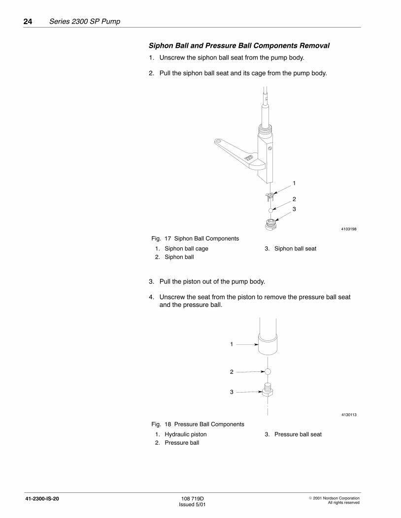
1. Unscrew the siphon ball seat from the pump body.
2. Pull the siphon ball seat and its cage from the pump body.
4103198
1
2
3
Fig. 17 Siphon Ball Components
1. Siphon ball cage2. Siphon ball
3. Siphon ball seat
3. Pull the piston out of the pump body.
4. Unscrew the seat from the piston to remove the pressure ball seatand the pressure ball.
4130113
1
2
3
Fig. 18 Pressure Ball Components
1. Hydraulic piston2. Pressure ball
3. Pressure ball seat
Series 2300 SP Pump 25
� 2001 Nordson CorporationAll rights reserved
108 719DIssued 5/01
41-2300-IS-20
5. Inspect both the pressure and siphon balls and their seats for wear ordamage. Replace if necessary.
WARNING: Do not heat Type R solvent with an open flame orin an unregulated heating device. Do not heat Type R solventabove 246 �C (475 �F).
6. Heat a container of Type R solvent to the melting temperature of theadhesive being used. Clean all components of the pump.
Cleaning Pump Components
If necessary, follow this procedure to clean the pump components.
WARNING: Risk of fire or explosion. Do not heat NordsonType-R cleaning fluid above 246 °C (475 °F). Do not heatcleaning fluid with an open flame or in an unregulated heatingdevice.
1. Use one of the following methods to clean the components:
� Place the components, except for O-rings, in a container ofType-R cleaning fluid and heat the fluid above the melting point ofthe adhesive.
� Use a flameless heat gun to heat the components, except forO-rings.
2. Scrub the components with a fine-bristled brush and wipe them with aclean, dry cloth.

4131122A
1
2
Series 2300 SP Pump26
� 2001 Nordson CorporationAll rights reserved
108 719DIssued 5/01
41-2300-IS-20
Siphon Ball and Pressure Ball Components Installation
1. Insert the pressure ball into the plunger end of the piston.
2. Apply Loctite to the threads of the pressure ball seat and screw it ontothe piston. Tighten the seat to 4.07−6.78 N�m (3−5 ft.-lb).
3. Insert the piston into the pump body.
4. Place the siphon ball onto the siphon ball seat.
5. Attach the siphon ball cage to the seat. If the cage does not fitsecurely, bend the legs of the cage slightly inward.
6. Apply Loctite to the threads of the seat and screw it into the pumpbody.
Pump Components Installation
1. Put the backup ring and O-ring on the crossover tube. Apply NeverSeez lubricant to the threads of the crossover tube and screw it intothe pump body.
NOTE: All adhesives must be removed from the seal cavity and theretaining-ring groove in the pump body before the seal is installed.
2. Apply O-ring lubricant to the pump seal. Pull the piston up throughthe top of the pump body.
3. Put the pump seal, with the groove facing the pump body, on thepiston, and then put the washer on the piston.
4. Slide the piston down to help guide the seal and washer into place inthe pump body.
5. Use a retaining-ring tool to snap the retaining ring into place.
6. If the U-cup is being replaced, insert the U-cup into the upper face ofthe pump mount, with the groove facing up and install a new retainingring to hold the U-cup in place.
Fig. 19 Pump Components
1. Pump body2. Hydraulic piston

Series 2300 SP Pump 27
� 2001 Nordson CorporationAll rights reserved
108 719DIssued 5/01
41-2300-IS-20
7. Place the O-ring over the air cylinder mount on the upper surface ofthe pump mount.
8. Guide the upper part of the pump body and the piston through thebottom hole in the pump mount.
NOTE: The piston must be inserted through the tab lock washer andthe locking nut before it passes through the top hole in the mount.
9. Secure the pump body to the pump mount with the locking nut. Donot tighten. There is a stop in the bottom of the pump bracket.Rotate the pump body clockwise until it rests against the stop.
10. Install the shifter fork onto the piston. Refer to Replacing the ShifterFork.
11. Install one piston cup washer, one piston cup, and the piston sealwasher onto the piston in the proper order. The curved edge of thepiston cup should be pointing down. Refer to Replacing thePiston Cups.
NOTE: To prevent damage to the upper piston cup, do not install theupper piston cup and washer before installing the air cylinder andactuator assembly on the pump.
12. Install the actuator and air cylinder assembly onto the pump. Refer toActuator and Air Cylinder Assembly Reassembly.
13. Install the upper piston cup, washer, and nut.
14. With the valve spool end centered in the opening of the cylinder head,install the cylinder head.
15. Secure with screws and tighten to 5−6 N�m (45−55 in.-lb).
16. Install the pump in the applicator and resume normal operation.

Series 2300 SP Pump28
� 2001 Nordson CorporationAll rights reserved
108 719DIssued 5/01
41-2300-IS-20
Pump Installation
NOTE: If you are replacing an old pump that has a pump cover bracket,remove the bracket and install it on the new pump.
1. Make sure the pump pan is positioned correctly.
2. Lower the pump into the applicator until the crossover tube seats inthe manifold.
3. Secure the pump to the applicator with the screws and washersremoved earlier. Tighten to 12.20−13.56 N�m (9−10 ft-lb).
4. Connect the air input line to the actuator.
System Restoration
1. Replace the pump cover.
2. Place the circuit breaker in the ON position and wait for the READYlight to turn on.
3. Place a container under the manifold drain valve or valves.
4. Standard manifold filter: Open the drain valve.
Reverse-flush manifold filter: With the manifold filter in the RUNposition, open the right-side drain valve.
5. Increase pump air pressure until clean adhesive flows from the drainvalve. This will purge the system of trapped air.
6. Reduce the pump air pressure to 0.
7. Close the drain valve.
8. Return the air pressure to the normal operating setting and resumeoperation.

Series 2300 SP Pump 29
� 2001 Nordson CorporationAll rights reserved
108 719DIssued 5/01
41-2300-IS-20
The Series 2300 pump service kits provide parts for fast, efficient repairs.Buying the service kits costs less than buying the individual parts.
The Series 2300 pump service kits consists of maintenance parts fornormal wear items. They eliminate the worry and expense of out-of-stocksituations for regular maintenance parts. These kits provide protection foradditional repairs that are needed after prolonged usage. They enablequick replacement of major parts, resulting in maximum uptime.
The following table includes the service kit part numbers for the Series2300 piston pump. The parts in the kit should be replaced as a part ofroutine maintenance.
Part Description Quantity
164 610 Service kit, pump with solenoid, SP-23, 230 VAC 1
165 758 Service kit, pump with solenoid, SP-23, 255 VAC 1
161 427 Service kit, pump without solenoid, 14:1, SP-23 1
Item Part Description Quantity Note
— 1011 333 Pump, piston, 14:1, SP-23, G2 1
1 982 147 � Screw, hex-head, cap, M6 x 120 4
2 983 409 � Washer, lock, split, M6 4
3 986 602 � Retaining ring, internal, 81, invert 1
4 273 138 � Washer, 0.799 OD x 0.543 ID x 0.034 in. thick 1
5 273 139 � Seal, pump 1
6 973 402 � Plug, pipe, socket, flush, 1/8 in. 1
7 273 108 � Body, hydraulic pump 1
8 274 546 � Tube, crossover, pump 1
9 900 344 � Lubricant, Never Seez, 8 oz. can AR
10 954 013 � Backup ring, single, 7/16 x 9/16 in. 1
11 940 133 � O-ring, Viton, 0.426 ID x 0.070 in. wide 1
12 982 135 � Screw, hex-head, cap, M6 x 30 1
13 983 410 � Washer, flat, narrow, M6 1
14 155 085 � Piston pump, 14:1, SP 23 1
15 985 302 � Pin, roll, 0.125 x 0.500 in. 1
16 503 709 � Seat, ball, pressure 1
Continued on next page
5. Series 2300 SP PumpParts List
Series 2300 Service Kits
Series 2300 Piston Pump Parts List

Series 2300 SP Pump30
� 2001 Nordson CorporationAll rights reserved
108 719DIssued 5/01
41-2300-IS-20
Item Part Description Quantity Note
17 900 470 � Adhesive, threadlocking, Loctite 272 AR
18 503 696 � Cage, ball, siphon 1
19 900 001 � Ball, 440 stainless, 0.500 in., 50 1
20 503 695 � Seat, ball, siphon 1
21 900 000 � Ball, 440 stainless, 0.375 in., 50 1
22 155 079 � Fork, magnetic, assembly 1
23 274 525 � Mount, pump, 2300 unit 1
24 952 100 � U-cup, Viton 1
25 900 493 � Lubricant, Parker, hi-temp AR
26 940 332 � O-ring, Viton, 2.000 x 2.125 x 0.063 in. 2
27 983 446 � Washer, piston cup, SP 2
28 163 039 � Cup, piston, SP 2
29 983 445 � Washer, piston seal, SP 1
30 984 092 � Nut, hex, lock, torque, M6, class 10 1
31 309 822 � Manifold, air, SP 1
32 333 137 � Head, cylinder, SP, machined 1
33 1014 650 � Service kit, bumper, SP, G2 1
34 984 090 � Hex nut lock, torque ,M8 1
35 982 028 � Screw, socket-head, M5 x 20 4
36 333 555 � Valve assembly, SP 1
37 211 228 � SP lubricating oil 2
38 940 181 � O-ring, Viton, 0.739 ID X0.070 wide 4
39 337 796 � Bracket, cover, pump, SP 2
40 983 402 � Washer, flat, narrow, M4 2
41 983 403 � Washer, lock, split, M4 AR
42 982 308 � Screw, pan-head, M4 x 10 1
43 973 007 � Nipple, steel, 1/8 in. NPT X 2.0 in. 1
44 333 560 � Spring, wave, SP pump 1
45 155 057 � Detent, upper, SP 2
46 982 059 � Screw, socket-head, M4 x 8 1
47 155 075 � Actuator, magnetic, assembly, SP 1
48 155 068 � Can, SP 1
49 155 067 � Detent, lower, SP 1
50 986 714 � Retaining ring, internal, 156, bowed 1
51 274 568 � Tubing, aluminum, 1/4 in. OD 1 A
52 971 400 � Elbow, male, 0.25 in. T X 1/8 in. NPT 1 A
53274 669276 872
� Solenoid valve/wiring assembly (non-380 Y V units)Solenoid valve/wiring assembly, 255 V 1
54 984 534 � Nut, lock, bearing, PN-06 1
55 983 183 � Washer, lock, bearing, W-06, 1
56 971 151 � Connector, male, 0.25 in. T X 1/8 in. NPT 1 A
NOTE A: P/N’s 971151 and 971 400 are required whenever new tubing is installed.
AR: As Required
Series 2300 Piston PumpParts List (contd)

Series 2300 SP Pump 31
� 2001 Nordson CorporationAll rights reserved
108 719DIssued 5/01
41-2300-IS-20
4131193A
321
2
3
4
5
6
7
8 9
1011
1213
2214
15
16 1721
18
19
20
23
24 25
30
27
28
29
27
28
26
55
54
50
49
48
35
47
45
44
42
41
43
35
37
31
46
40
53
52
51 56
25
34
26
33
36
38
39

Series 2300 SP Pump32
� 2001 Nordson CorporationAll rights reserved
108 719DIssued 5/01
41-2300-IS-20
Item Part Description Quantity Note
— 165 769 Filter regulator assembly, Series 2300 1
1 165 735 � Regulator, filter, air, 1/4 NPT 1
2 165 870 � � Service kit, filter element 1
3 165 878 � � Service kit, filter bowl 1
4 901 258 � Gauge, air, 1/8 NPT, 90 psi 1
5 973 489 � Nipple, brass, 40, 1/4 in., 2.50 in. (4 hose applicators) 1
6 973 372 � Bushing pipe, 1/4 X 1/8 1
4131199A
1
5
4
2
3
6
Air Pressure Regulator PartsList