(part 3 of 3 parts) building the turner t-40a.moirier.free.fr/construction/dossiers de...
TRANSCRIPT
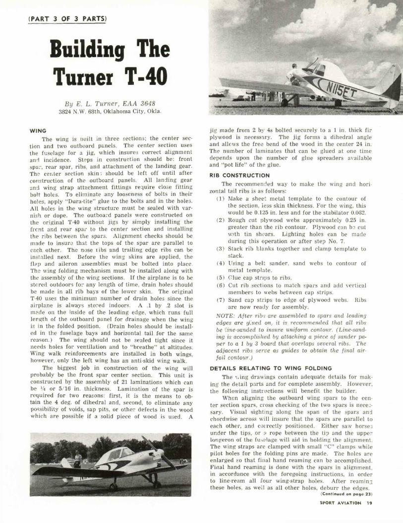
(PART 3 OF 3 PARTS)
Building TheTurner T-40
By E. L. Turner, EAA 36483824 N.W. 68th, Oklahoma City, Okla.
WINGThe wing is Diiilt in three sections; the center sec-
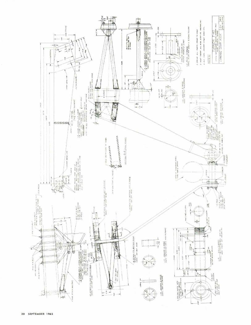
tion and two outboard panels. The center section usesthe fuselage for a jig, which insures correct alignmentand incidence. Steps in construction should be: frontspar, rear spar, ribs, and attachment of the landing gear.The cei.ter section skin-, should be left off until afterconstruction of tho outboard panels. All landing gearand wing strap attachment fittings require close fittingbolt holes. To eliminate any looseness of bolts in theirholes, apply "Dura-tite" glue to the bolts and in the holes.All holes in the wing structure must be sealed with var-nish or dope. The outboard panels were constructed onthe original T-40 without jigs by simply installing thefrcnt and rear spar to the center section and installingthe ribs between the spars. Alignment checks should bemade to insuro that the tops of the spar are parallel toeach other. The nose libs and trailing edge ribs can beinstalled next. Before the wing skins are applied, theflap and aileron assemblies must be bolted into place.The wing folding mechanism must be installed along withthe assembly of the wing sections. If the airplane is to bestored outdoors for any length of time, drain holes shouldbe made in all rib bays of the lower skin. The originalT-40 uses the minimum number of drain holes since theairplane is always stored indoors. A .1 by .2 slot ismade on the inside of the leading edge, which runs f u l llength of the outboard panel for drainage when the wingis in the folded position. (Drain holes should be install-ed in the fuselage bays and horizontal tail for the samereason.) The wing should not be sealed tight since itneeds holes for ventilation and to "breathe" at altitudes.Wing walk reinforcements are installed in both wings,however, only the left wing has an anti-skid wing walk.
The biggest job in construction of the wing willprobably be the front spar center section. This unit isconstructed by the assembly of 21 laminations which canbe \'.\ or 5/16 in. thickness. Lamination of the spar isrequired for two reasons: first, it is the means to ob-tain the 4 deg. of dihedral and, second, to eliminate anypossibility of voids, sap pits, or other defects in the woodwhich are possible if a solid piece of wood is used. A
jig made from 2 by 4s bolted securely to a 1 in. thick firplywood is necessary. The jig forms a dihedral angleand allows the free bend of the wood in the center 24 in.The number of laminates that can be glued at one timedepends upon the number of glue spreaders availableand "pot life" of the glue.
RIB CONSTRUCTIONThe recommended way to make the wing and hori-
zontal tail ribs is as follows:(1) Make a sheet metal template to the contour of
the section, less skin thickness. For the wing, thiswould be 0.125 in. less and for the stabilator 0.082.
(2) Rough cut plywood webs approximately 0.25 in.greater than the rib contour. Plywood can b? cutwith tin shoars. Lighting holes can be madeduring this operation or after step No. 7.
(3) Stack rib blanks together and clamp template tostack.
(4) Using a belt sander, sand webs to contour ofmetal template.
(5) Clue cap strips to ribs.(6) Cut rib sections to match spars and add vertical
members to webs between cap strips.(7) Sand cap strips to edge of plywood webs. Ribs
are now ready for assembly.NOTE: After ribs are assembled to spars and leadingedges are tf.ued on, it is recommended that all ribsbe 'line-sanded to insure uniform contour. (Line-sand-ing is accomplished by attaching a piece of sander pa-per to a 1 by 3 board that overlaps several ribs. Theadjacent ribs serve as guides to obtain the final air-foil contour.)
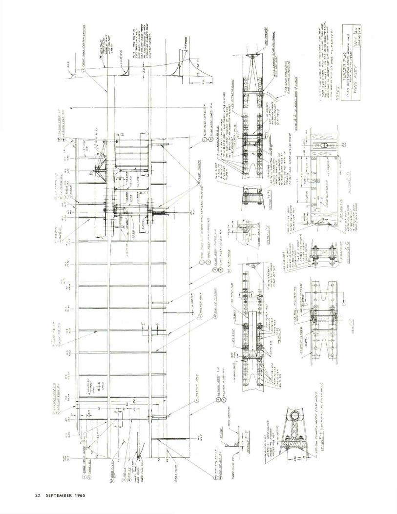
DETAILS RELATING TO WING FOLDINGThe \.ing drawings contain adequate details for mak-
ing the detail parts and for complete assembly. However,the following instructions will benefit the builder.
When aligning the outboard wing spars to the cen-ter section spars, cross checking of the two spars is neces-sary. Visual sighting along the span of the spars andchordwise across wi l l insure that the spars are parallel toeach other, and coirectly positioned. Either saw horsejunder the tips, or ;i rope between the tip and the upperlongeron of the fu^o'.age will aid in holding tho alignment.The wing straps are clamped with small "C" clamps whilepilot holes for the folding pins are made. The holes areenlarged so that f inal hand reaming can be accomplished.Final hand reaming is done with the spars in alignment,in accordance with the foregoing instructions, in orderto line-ream all four wing-strap holes. After reaminjthese holes, as well as all other holes, deburr the edges.
(Continued on page 23)
SPORT AVIATION 19
20 SEPTEMBER 1965
^=?•( © ®|!
; e
iJi!o
T L.
;S ? '
Hi1t &
IB^UL^" 5 5 i * £ ' l!«!!V J
\ :;!*\ HK\!l\ *-.<j?
V SIt\
>isiii
>!'i ,A=«': lu
An* \•. \
k41
It
X—11ij4
?!,1|? Si!3 o•< "t-<*i$< 3i»•s^?. 1S^" 'Jj!5 ? h «x t
^^^*. 0N
,»1ill;Mill
: '^n |ti« •'«h MhKarf.
1l~>a«KCk
a^Jr
<k*~f51
ijS.5
S?S-*s^s"- "i _
L
SPORT AVIATION 21
22 SEPTEMBER 1965
TURNER T-40 . . .(Continued from pogc 19}
Should excessive clearance between the folding pinsand the reamed holes be encountered, a build-up of thepin diameter can be accomplished by having the pinshard chrome-plated and ground to the desired diameter.The folding pins and their mating holes are probablythe only really critical connection in the whole design.This can be appreciated by realizing that all of the bend-ing and torsional ioads of the wing are carried throughthese connections. On the original T-40, one of the up-per front spar f i t t ing holes was oversize approximately0.0015 in. This f i t t ing was not corrected in order to de-termine how critical the tolerances really were. Afterfour years of flying, this excessive clearance has causedno problem at all. So, there is a little leeway in assembly.However it is not recommended that the tolerances speci-fied on the drawings be ignored.FLIGHT TESTING
The standard procedure for flight testing should befollowed. Several high speed taxi runs should be madeto feel out the effectiveness of the controls before thefirst flight is attempted. It is generally recommendedthat the first flight be restricted to a few feet abovethe ground and then landed. This will give the pilot anadditional opportunity to get the feel of the controls.The next flight should be a normal take-off and smoothclimb-out until approximately 1,000 ft. is gained. Theoriginal T-40 was trimmed to fly hands off the first flight.
The T-40, as in the case of very clean airplanes withconventional landing gear, has high drag in the threepoint attitude. With the all flying horizontal tail, theT-40 can be pulled off the ground too soon, thereby get-ting the airplane in an extreme nose high attitude whichputs the airplane on the backside of the power requiredcurve. If this condition is encountered during take-off,the pilot should lower the nose gradually to gain speedor. providing there is sufficient runway left, the powershould be reduced and a landing made. A normal take-oft procedure is recommended where the stick is heldforward to raise the tail and as flying speed is reached,the stick is eased back to initiate take off.ADDITIONAL PERFORMANCE INFORMATION
The following performance data applies to the T-40with a C-85 engine and a modified McCauley propellerof 65 in. diameter and 63 in. pitch diameter. Take-offrun, density al t i tude of approximately 1,000 ft., wasaround 900 ft. Take-off run at Albuquerque, N.M., ele-vation of 5.200 ft., density altitude of 8,700 ft., was ap-proximately 3 200 ft. with less than 5 mph headwind.This take-off was made with maximum overload grossweight of approximately 1,060 lbs.
At a density altitude of 2,200 ft., the maximum speedof the airplane was checked at 170 mph. Cruising speed,depending on the amount of fuel consumption, can be
from 135 mph up. At 22 in. HG at 2,500 rpm. cruisingspeed is 143 mph with a fuel consumption of 5.2 gph.Maximum altitude to date was 12,500 ft. with power left.At the time, the maximum altitude would appear to be15,000 ft. These figures are given for the 85 hp Con-tinental engine. The propeller installed was made byAnderson Propeller Company, Du Page County Airport,West Chicago, 111. Price for a mirror finished anodizedpropeller was 890.00.
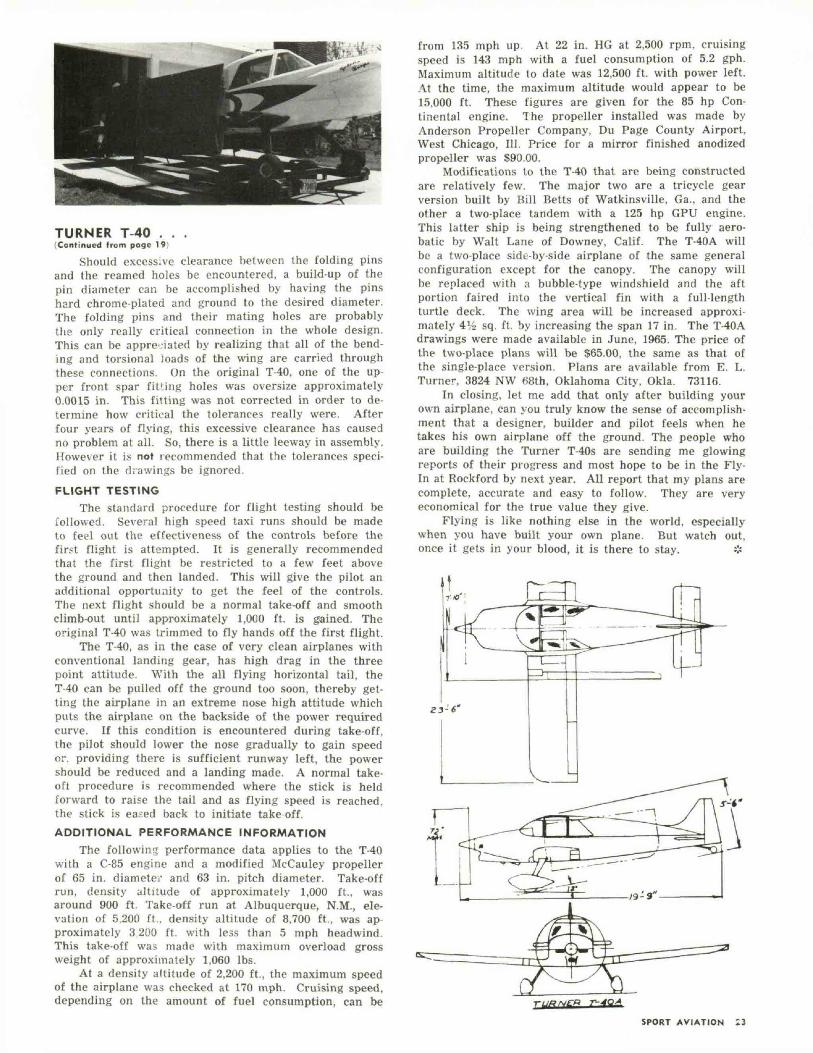
Modifications to the T-40 that are being constructedare relatively few. The major two are a tricycle gearversion built by Bill Belts of Watkinsville, Ga., and theother a two-place tandem with a 125 hp GPU engine.This latter ship is being strengthened to be fully aero-batic by Walt Lane of Downey, Calif. The T-40A willbe a two-place side-by-side airplane of the same generalconfiguration except for the canopy. The canopy willbe replaced with n bubble-type windshield and the aftportion faired into the vertical fin with a full-lengthturtle deck. The wing area will be increased approxi-mately 4J,i> sq. ft. by increasing the span 17 in. The T-40Adrawings were made available in June, 1965. The price ofthe two-place plans will be $65.00, the same as that ofthe single-place version. Plans are available from E. L.Turner, 3824 NW «8th, Oklahoma City, Okla. 73116.
In closing, let me add that only after building yourown airplane, can you truly know the sense of accomplish-ment that a designer, builder and pilot feels when hetakes his own airplane off the ground. The people whoare building the Turner T-40s are sending me glowingreports of their progress and most hope to be in the Fly-In at Rockford by next year. All report that my plans arecomplete, accurate and easy to follow. They are veryeconomical for the true value they give.
Flying is like nothing else in the world, especiallywhen you have built your own plane. But watch out,once it gets in your blood, it is there to stay. %
SPORT AVIATION