part 1 h. metal reinforcement placing all j. all
TRANSCRIPT

MEMO TO DESIGNERS AUGUST 1989 17-140
SPT CO. SUPPLEMENT AL REQUIREMENTS TO CHAPTER 8 AREA SPECIFICATIONS
The following Specifications should be used in lieu of the corresponding portions of the AREA Specifications for concrete railroad bridges and other structures.
CHAPTERS
Part 1
H. Metal Reinforcement Placing
5. Spacing of Reinforcement (and Prestressing Steel)
Following the sixth paragraph of this section, add the following:
''Maximum number of strands per bundle is 4. Minimum clear distance between bundles is 2 inches."
8. Bending Details for Ties, Stirrups, Spirals
All column ties, closed and open stirrups, ends of column spirals, shall end with 135° hooks. 135° hooks on column ties and ends ofcolumn spirals shall have a 10-inch extension at free ends of bar.
J. Proportioning
1. General
All superstructure concrete in railroad structures shall be be air entrained per item 4, this section.
Other additives in addition to air entraining agents may be used to improve workability, retard set, accelerate set, etc.; however, approval of railroad is required.
Calcium chloride is not permitted in prestressed concrete structure.
5. Strength of Concrete Mixrures
The 28-day compressive strengths ofconcretes used for design shall be shown on the plans.
The 28-day compressive strengths of concrete to be used for placement in a structure shall be indicated on plans and shall be arrived at in accordance with method 2.
Supersedes Memo to Designers 17-140 dated March 1980
1

MEMO TO DESIGNERS AUGUST 1989 17-140
Part 2
Plain and Reinforced Concrete Members
C. Design Loads
6. Other Lateral Forces
Structures located in zones 2 or 3 on the Seismic Risk Map in the Uniform Building Code, current edition, shall be designed taking seismic forces into account. Underground structures and retaining walls are excluded from these seismic provisions.
a. Earthquake forces to be used in the design of bridge structures shall be determined in accordance with the Califomia Department of Transportation earthquake design criteria.
8. Minimum Lateral Forces
The minimum lateral force to be used in the design of a pier or bent shall be 20 kips applied horizontally at the top of rail at right angles to track.
G. Bond and Anchorages
6. Hooks
a. 3. Delete: "either a 90° or'' Add: at end of sentence - "except for column ties the extension shall be 10 inches
minimum."
/ . Design ofColwnns
2. Spirally Reinforced Columns Longitudinal Reinforcement
For structures situated in zones 2 and 3 on the Seismic Risk Map of the Uniform Building Code the maximum pg. shall be 0.06 based on the area of the column core.
3. Tied Columns Longitudinal Reinforcement
For structures situated in zone 2 or 3 on the Seismic Risk Map of the Uniform Building Code the maximum pg. shall be based on the area of the core.
2

MEMO TO DESIGNERS AUGUST1989 17-140
Part 3 ·
Footing Foundations
F. Details ofDesign
6. Footings in E.Q. Areas
For structures located in zones 2 or 3 on the Seismic Risk Map in the Uniform Building Code, current edition, supports which consist of multiple columns shall have a combined footing.
Part 16
SPT Co. Supplemental Specifications for Design of Box Culverts
16-a-l. General:
Part 16-a is a supplement to the AREA Manual of Recommended Practice. Where this supplement expands or modifies the AREA manual, the provisions of the supplement are to be followed; otherwise, the manual controls.
16-a-2. Classification ofSoils:
2.1 Soil Types
2.1.1 Oean Sand and Gravel: GW, GP, SW, SP.
2.1.2 Dirty Sand and Gravel of restricted permeability: GM, GM-OP, SM, SM-SP.
2.1.3 Stiff residual silts and clays, silty fine sands, clayey sands and gravels: CL, ML, CH, MH, SM, SC, GC.
2.1.4 Very soft to soft clay, silty clay, organic silt and clay: CL, ML, OL, CH, MH, OH.
16-a-3. Design Principles and Loads:
3.1 Dead Loads
3 . 1.1 Weight of earth for design calculations shall be taken at 120 lbs per cu fL
3.1.2 Unifonnly distributed loads per square foot to top of the box for various depths of
fill "D;' are shown on Fig. SP2.
3

MEMO TO DESIGNERS AUGUST 1989 17-140
3.2 Live Loads
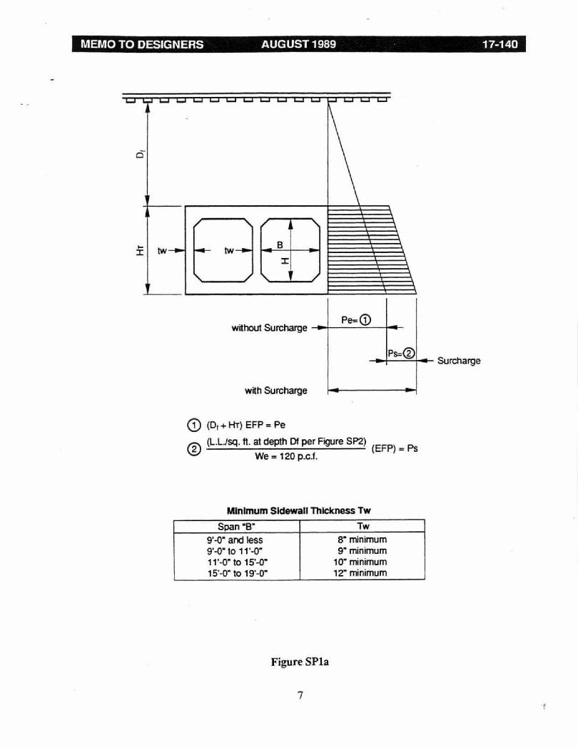
3.2.1 The live load for each track shall be Cooper E-80. The distribution of the live load to the culvert shall be in accordance with Figures SPl and SPla. ·
3.2.2 Uniformly distributed live loads per square foot to the top of the box for various values of"D;' are shown on Figure SP2.
3.3 Impact
3.3.1 Impact loads shall be distributed to the top slab and floor of the box as for live load and shall be equal to the following percentages of the live load:
For Dr= 0.67' - I= 40% then decreasing uniformly to Dr= 10' - I= 0%
3.3.2 Uniformly distributed impact loads per square foot to the box for various depths of fill ''D/" are shown on Figure SP2.
3.4 Lateral Pressures
3.4.1 Lateral pressures resulting from the dead and live surcharge loads shall be as follows:
Soil Type 2.1.1 or 2.1.2 - E.F.P. = 36 p.c.f. Soil Type 2.1.3 -E.F.P. = 45 p.c.f. Soil Type 2.1.4 - Soils investigation required to determine suitability of
soils as a backfill material and establish E.F.P. value corresponding to soils to be used for backfill material.
16-a-4. Details ofDesign:
4.1 Cut-off Collars and Cut-off Walls
4.1.1 Boxes situated in Type 2.1.1 or 2.1.2 soils shall be designed with cut-off collars located near the inlet end of the structure; unless specifications for job specify that material for backfill will not permit percolation and resultant piping and that written assurance is furnished such that backfill placement will be under supervision of a registered Civil Engineer specializing in geotechnical engineering.
4.1.2 All boxes shall have cut-off walls at the ends of both inlet and outlet aprons.
4.1.3 Allowable stresses in materials shall conform to Chapter 8, Part 2.
4

MEMO TO DESIGNERS AUGUST 1989 17-140
16-a-5. Derails ofConstruction:
5.1 Backfill
5.1.1 Backfill materials shall be placed in layers not more than 12" thick and shall be compacted to a relative density of 90%, except for the top 2 ft. (under the ballast) shall be compacted to 95%. Relative density shall be determined in accordance with the modified AASHrO procedure. ·
5

»Lo
ngitu
dina
l Sec
tion
- Sh
owin
g D
istr
ibut
ion
of L
oads
and
Oth
er D
etai
l
MEMO TO DESIGNERS AUGUST 1989 17-140
Minimum Sidewall Thickness Tw
Span “B- Tw
9 '-0 ' and less 8 ’ minimum 9'-0* to 1V -0 ’ 9 ’ minimum 1V-0" to 15'-0" 10" minimum l 5 ’-0" to 19’-0’ 12’ minimum
Figure SPla
7
(D (D1 + HT) EFP = Pe
@ (l.Usq. ft . at depth Of per Figure SP2) (EFP) = Ps
We= 120 p.c.f.

MEMO TO DESIGNERS AUGUST 1989 17-140
8

MEMO TO DESIGNERS AUGUST 1989 17-140
Part 17
SPf Co. Supplemental Specifications for Design Materials and Construction of Prestr~d Concrete Structures
B. General Considerations
5. Design Restrictions
The minimum 28-day compressive strength of concrete used in design of prestressed concrete structures shall be:
Post-tensioned structures - 4,000 psi Pre-tensioned structures - 5,000 psi
The use of notched girders or beams is not permitted.
The use of corbels or brackets to support girders or beams is not permitted.
All post-tensioned structures shall be bonded (grouted).
At the end of skew bridges, the approach end of the suppon for each track shall be at right angles to centerline of track.
Skews in excess of 15° are not permitted for continuous strucrures. Where conditions preclude any other solution. the skew proposal will be considered as a special case and will require special structural consideration and proof of adequacy.
Post-tensioned, continuous structures shall have two stages--prestressing and concrete placement by stages. See Section H, Se of this supplement.
Box shape sections and I-shape sections shall have intermediate diaphragms, in addition to the end diaphragms, as follows:
Spans 35 ft. to 50 ft. - One intermediate diaphragm Spans 51 ft. to 75 ft. -Two intermediate diaphragms Spans over 76 ft. -Three intermediate diaphragms
minimum per span, the definite number to be considered in each case depending on the particular design, span lengths, member rigidities, etc.
Precast single cell box girders shall have transverse tie rods installed at the ends, and at each interior diaphragm. Minimum size tie rod is 1¼" diameter.
9
MEMO TO DESIGNERS AUGUST 1989 17-140
Tie rods shall be protected in one of the following ways:
a. Rods, plates, and nuts shall be hot dip galvanized per ASTM A123, and A153, or
b. All parts left plain, but the void between rod and hole to be pressure grouted. Nut and plate assembly to be recessed deep enough that the assembly can be protected with grout
U-shape continuous structures shall be supported at pier and abutments under the girder reaction points. The support device shall provide for longimdinal and rotational movement at the abutments. For single pier bridges the support device on the pier shall provide for rotational movement. On multiple pier bridges, the support device shall provide both longitudinal and rotational movement except at the central pier or piers, which are to handle longitudinal forces, where rotational movement only may be provided. Stability to handle horizontal forces to be obtained by pier base fixity.
U-shape simple span structures shall be supported under the girder reaction points.
Minimum depth of bottom slab in U-shape structures= 22 inches.
U-shape structures shall have clearances and dimensions in conformance with Appendix V.
H. Allowable Steel and Concrete Stresses
2. Prestressing Steel
b. Stress at design loads change 0.55 fs' to 0.6 fs '
4. Concrete
a. Temporary stresses Tension:
Delete: lines 1, 2, 3 and 4.
Substitute: Precast members which are installed into the structure as finished units.
For members without nonrestressed reinforcement; 0. For members with nonrestressed reinforcement provided to resist the tensile force in the concrete computed on basis of an uncracked section; 0.
10

MEMO TO DESIGNERS AUGUST 1989 17-140
Precast members which are installed into the structure as unfinished units, e.g. precast, prestressed I or similar sections upon which a composite deck is to be placed.
For members without non-prestressed reinforcement; 0. For members with non-prestressed reinforcement provided to resist the tensile force in the concrete computed on the basis of an uncracked section; 6-Jfci
5. Special Requirements for Post-Tensioned Structures
a) Post-tensioned simple spans shall be designed for a minimum compression of 100 psi at the top, and for a minimum compression ofzero at the bottom, for any cross section and for any stage of prestressing and case of loading. There shall be sufficient straight tendons top and bottom to produce a uniform compression of 200 psi over the crosssection. Prestress can be applied in a single stage for spans 80 ft. and under (60 ft. and under for U-shape structures), stressing the straight tendons first, sequentially alternating between top and bottom tendons to keep as uniform a stress pattern as possible over the cross-section, and then continuing on stressing the draped tendons until stressing is complete.
b) Simple spans over 80 ft. in length, ( 60 ft. for U-shape structures), shall be prestressed in two stages. First stage pres~ss shall be applied when the last placed concrete has attained a cylinder strength of 1500 psi and shall be applied by tensioning the straight tendons, alternating sequentially between top and bottom tendons, to create a uniform compression of200 psi ~ over the cross-section. The second stage shall be the application of the remaining portion of the design pres tress force when the last placed concrete has reached a strength as required at transfer by the basic AREA Specifications.
c) In U-shape simple span structures the tendons referred to in a) and b) above shall be distributed through the structure cross-section approximately as follows:
1) Referring to the straight tendons first to produce a uniform compression of 200 psi stressed over the cross-section, the tendons located below the neutral axis shall be distributed uniformly across the bottom slab. The straight tendons above the neutral axis shall be located in the top flange portion of the girders.
2) The placement of strands shall be symmetrical about and approximately ½ of the total number of strands shall be located in the bottom slab between girders.
d) In U-shape, simple span structures, additional transverse reinforcement shall be placed in the bottom slab at each end of the span. This reinforcement is in addition to the reinforcement calculated for the slab to handle loading conditions and is to be placed in a 2'-6" wide strip at the ends of the slab. This reinforcement is to run parallel to the end
11

MEMO TO DESIGNERS AUGUST 1989 17-140
of the slab. The amount of extra reinforcement req~d is -
For spans with ends at right angles to the track and skews up to 15° from the normal to the track 6.0 sq. in.
For spans with ends skewed from 15° to 25°from the normal to the track 8.0 sq. in.
For spans skewed over 25° from the normal to the track 12.0 sq. in.
e) Post-tensione4 continuous structures shall be designed for a minimum compression of 200 psi at the top and 50 psi minimum compression at the bottom in spans, and 50 psi minimum compression at the top and 200 psi minimum compression at the bottom for sections over the suppons, for any stage of prestressing and case of loading.
f) Cast-in-place, continuous, post-tensioned structures shall have sufficient straight tendons placed in both top and bottom fibers to produce a calculated uniform compression over the entire section of 200 psi. The prestress in the straight tendons (1st stage prestress) to be applied when the last placed concrete has reached a cylinder strength of 1500 psi. The stressing of these straight tendons shall be applied by. alternating sequentially betwee_n top and bottom tendons to keep as uniform stress as possible over the cross-section during the stressing procedure. The second stage shall be the application of the remaining portion of the design prestress force when the last placed concrete has reached a strength as required at transfer by the basic AREA Specification.
g) The above procedure e) and f) to be applied in conjunction with a concrete placement schedule for the structure in which the span sections are placed first and sections over the suppons to the inflection points placed second. This two-stage procedure applies to spans 100 ft. or less (80 ft or less for U-shape structures), the placement schedule shall be in 3 stages; spans first; over supports to inflection points second; and closure sections 8 ft long at the inflection points last On the longer spans it may be required to subdivide the sequence steps into placement sections depending on the structure type and amount of nonstressed reinforcement used to control shrinkage cracking. For each stage of concrete placement, the entire structural cross-section shall be completed before moving to next stage. When casting the stage over suppons, the concrete placement shall proceed from the outer ends to the support
h) In U-shape continuous post-tensioned structures, the tendons referred to in e) and f) which are placed to produce a uniform compression of 200 psi over the entire section shall have the tendons distributed in accordance with paragraph c) - 1) above.
i) In U-shape continuous structures, additional transverse reinforcement shall be placed in the bottom slab at each end of the bridge structure. This reinforcement is in addition to
12

MEMO TO DESIGNERS AUGUST 1989 17-140
the reinforcement calculated for the slab to handle loading conditions and is to be placed in a 2'-6" wide strip at the ends of the slab. This reinforcement is to run parallel to the end of the slab. The amount of extra reinforcement required is -
For strucrures with ends at right angles to the track and skews up to 15° from the normal to the track 10.0 sq. in.
j) For all U-shape structures in Sections Band Hare based on one independent U-shape supporting one track.
0. Cover a~ Spacing ofPrestressing Steel
2.1 Spacings Within Member Length
a) For spacing ofpost-tensioning ducts, refer to Appendix I, Pattern ofPrestressing Ducts for RR Bridges.
3.0 Draped Prestressing Steel
Add to paragraph: Maximum number of strands per bundle is 4. Minimum clear distance between bundles is 2-inches.
4.0 Strands in Pre-tensioned Members
In pre-tensioned single void box girders, two prestress strands shall be located in the area between the top of the box and a distance of 6" below top of box.
In pre-tensioned double void box girders, 4 prestress strands shall be located in the area between the top of the box and a distance of 6" below top of box.
Part 17
Pattern of Prestressing Ducts for SPT Co.
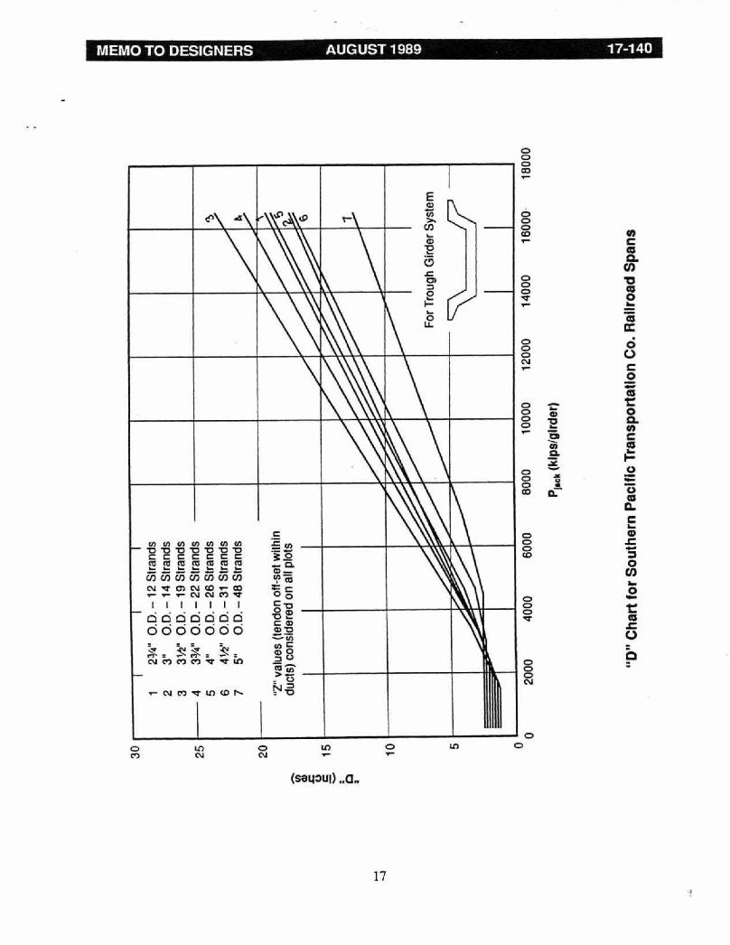
The details on pages 14 and 15 show the minimum clearances and spacing of prestressing ducts required by the Southern Pacific Transponarion Company. These details must be included in the plans for all SPT Co. underpasses. Pages 16 and 17 provide "D" values for these duct patterns. ' 'D" and "Z" values are defined in Memo to Designers 11-28.
The radius of curvarure of any duct-must not be less than 60 feet.
13

Duc
ts o
ver
3" O
.D. a
nd L
ess
Than
AW

Not
es:
1. F
or a
ll si
zes
of d
ucts
the
min
imum
rad
ius
of c
urva
ture
is 6
0 ft.
2.
Cle
aran
ces
show
n ap
ply
to a
ny p
art o
f a m
embe
r.
Duc
ts O
ver
4W’ O
.D.

“D”
Cha
rt fo
r S
outh
ern
Paci
fic T
rans
port
atio
n C
o. R
ailr
oad
Spa
ns
“D”
Cha
rt fo
r So
uthe
rn P
acifi
c Tr
ansp
orta
tion
Co.
Rai
lroa
d S
pans

Part 17
SPT Co. Supplemental Requirements for the Design of Prestressed Concrete Trestles for Railway Loading Using Box Beams
The keyways shown on the standard precast concrete box girder designs in Chapter 8, Part 17 of the AREA Specifications are not acceptable to the SPT Co. Therefore, the following detail shall be used for their bridges.
MEMO TO DESIGNERS AUGUST 1989 17-140
Part 20
SPT Co. Supplemental Specifications for Design of Shorings
20-a-l. General
Part 20-a is a supplement to the AREA Manual of Recommended Practice. Where this supplement expands or modifies the AREA Manual, the provisions of the supplement are to be followed, otherwise the manual controls.
Shoring which is to be installed adjacent to Railroad operating tracks shall be designed in accordance with the following provisions.
1.1 No shoring shall be installed closer than 8'-6" from the center line of any operating track.
1.2 Shoring between 8'-6" and 10'-0" face of shoring to centerline of track. when excavation is in natural ground or in fill ground which has been placed with proof of adequate compaction control, and shoring between 8'-6" and 13'-0", when excavation is in fill ground other than compaction controlled fill as stated above, shall be of a type whereby the shoring is installed in place prior to any excavation being performed, and whereby the excavation can be made with no possibility of disturbance or loss of the soil material being retained between the shoring and the track. Common shoring types fulfilling this requirement are Interlock-edge steel sheet piling, tongue and groove-edge precast concrete sheet piling, etc., which are driven into position prior to starting excavation. Shoring types using lagging elements which are placed as excavation proceeds are not permitted within the limits specified in this section.
1.3 Shoring outside the limits stated in Section 1.2 may be of types other than stated in Section 1.2 including types using lagging elements which are installed as the excavation proceeds.
1.4 Shoring, excavations, pits, etc., shall conform to the requirements ofExhibit "B" Relations with Railroad Company.
Excavations, pits, etc., within 13'-0" or less from centerline of track shall have protection by standard handrails.
Minimum clearance centerline of track to face of handrails = 8'-6" on tangent track and 9'-6" on curve track.
1.5 Where the provisions of this specification are more restrictive than the requirements of the Public Utilities Commission Orders, Department of Industrial Safety, OSHA, or other governmental agencies, these supplemental specifications shall apply.
19

MEMO TO DESIGNERS AUGUST 1989 17-140
20-a-2. Classification ofSoils
2.1 Soils to be retained as well as the soils depended upon for structural stability (passive resistance, shear strength, friction, etc.) shall be classified in accordance with the soil types listed in AREA Chapter 8, Part 5, B-4. This classification is to be a part of the calculations submitted with the shoring plans, and which is to be verified by Registered Professional Civil Engineer.
20-a-3. Loads on Shoring
3.1 The loading systems of this section apply to shorings which have some degree of flexibility such as cantilever sheet pile walls, or cantilever soldier pile-type systems, also sheet pile and soldier pile-type systems using tiebacks or raker struts in which the tiebacks or struts are not preloaded. This section does not apply to any excavation whereby one side of the excavation is cross-strutted to the opposite side (trench type), nor to tieback or raker strut systems wherein the ties or struts are preloaded.
3.2 Level Earth - 36-lb. per ft. EFP (Equivalent Fluid Pressure) is the minimum value to be used in designing shoring. This corresponds to Type 2 soil as defined in AREA Chapter 8, Part 5, B-4, C-2. EFP values for soils in Types 3, 4 and 5 shall be based on the values tabulated in AREA, Chapter 8, Part 5, B-4.
3.3 Where the <I> & C values of the soils have been ascertained by borings and tests and the values for the EFP have been established by a Registered Professional Civil Engineer specializing in geotechnical engineering, these values may be used in lieu of the tabulated values providing the <I> and C values determined by test have been r~uced by 15% to allow for the dynamic effect of train loadings on the retained ma.terials.
3.4 Surcharge - Minimum surcharge to be applied is 2-fe.et height of 110 p.c.f. earth.
3.5 Sloping Surcharge - Minimum EFP values shall be those from the curves for Type 2 soils, Chapter 8, Part 5, Appendix C; Sec. 3.3 is also applicable to sloping surcharge.
3.6 Coopers E-72 Railroad Surcharge Loading- Use values from Chart 3.6.
3.7 Alternate Computation- The load system of Sections 3.2 through 3.5 can be calculated on the basis of AREA Chapter 8, Part 5, Appendix B, Trial Wedge Method ofEarth Pressure Computation. Values from 3.6 must be added to the trail wedge computation to obtain values for total loads.
3.7 .1 The minimum values for retained soils shall be those stated for Type 2 soil, namely, unit wt.= 110 p.c.f., angle of internal friction <I>= 30° cohesion = 0. Section 3.3 is also applicable to this method; however, the <I> and C values determined by borings
20

NOTES
1. For each additional depth increase of X It. decrease intensity of pressure by 50%.
2. If total height of shoring is less than 5 ft. and X is less than 8'-6", V* Ph pressure should be assumed at the top.

' MEMO TO DESIGNERS AUGUST 1989 17-140
and tests shall be reduced 15% to allow for the dynamic effect of train loadings. This method will handle soils with both q, and C characteristics, also structures in excess of 20 feet in height ·
3.8 All retaining structures shall be safe against slip circle type failure.
20-a4. Loads on Shorings
4.1 The load systems in this section apply to excavations whereby one side of the excavation is strutted against the opposite side (trench-type) also to tie-back and raker strut systems wherein the ties or struts are preloaded.
4.2 The material for this section and following four sections are under development for future inclusion in this supplement
20-a-5. Allowable Stresses and Factors ofSafety
5.1 Structural Steel
Axial Tension= Fy (for A-36 Steel= 24,000 psi)1.5
Steel Sheet Pile Section: (AREA Chapter 8, Part 20, Section 7 - Anchor Rods)
Flexural Tension= Fy (for A- 36 = 24,000 psi) 15
Axial Compression ( L J2 New steel - 1st usage on subject job: Fa = 20,000 - 0. 4 ry
Other than above: Fa= 16,000-0.38(~r . Fb 14,400,000 24 000 .Flexural compression: = Ld ~ , psi
bt
5.2 Prestress Strand or Road
Allow working stress (other than tie-back)= (0.6) (Ultimate-Strength)
Allow working stress (used as tie-back) = (0.4) (Ultimate-Strength)
(If use as structural element exceeds 30 days, then the cable shall be protected from rust.)
22

MEMO TO DESIGNERS AUGUST 1989 17-140
5.3 Steel Wire Cable
. lb Rated Breaking Strength Allowable wor king 1oa d m s.=-----.;:;;.._----=--
2.5
(If use as strucrural element exceeds 30 days, then the strand shall be protected from rust.)
5.4 Concrete
All stress allowables to comply with AREA Chapter 8, Pan 2.
5.5 Timber
Compression perpendicular to the grain 450 psi
F 480,000 . < l600 .Compression parallel to the grain a= (L/d2 ) psi_ psi
Flexural stress 1700 psi Reduced to 1500 psi for members with a nominal depth of 8 inches or less.
Horizontal shear 140 psi
5.6 Factors of Safety
For anchor blocks, dead.men, etc. 2.0
In the use of passive pressure for stability. 2.0
In the use of soil shear strength and friction based on vertical loads. 1.5
Slip circle failure of structure as a whole, or any part except anchor blocks, dead.men, etc. 1.5
Slip circle failure of anchor bolts, dead.men, etc. 2.0
Soil bearing pressures - U.B.C. Section 29
5.7 No increase in stresses or reduction in safety factors as tabulated is permitted.
23

20-a-6 Shoring Plans
6.1 Shoring plans shall consist of the following:
Drawing showing dimensioned location with respect to track, plan view, elevations, sections and details. Drawing elements shall be fully dimensioned, materials specified and end connections detailed.
Structural calculations shall accompany the plans and shall show the design basis for the shoring and all elements.
Drawings and calculations shall be prepared by or under the immediate supervision of a Registered Professional Civil Engineer Licensed to use the title “Structural Engineer” or by a Registered Civil Engineer with a minimum of 5 years of experience specializing in the design of shorings. Both drawings and calculations shall be signed by the Registered Professional Engineer.
Philip C Warriner
JGS:jgf
24
Guy D . Mancarti