paraffin actuators in microfluidic systems - diva portal170538/fulltext01.pdfparaffin actuators in...
TRANSCRIPT

ACTAUNIVERSITATIS
UPSALIENSISUPPSALA
2007
Digital Comprehensive Summaries of Uppsala Dissertationsfrom the Faculty of Science and Technology 325
Paraffin Actuators in MicrofluidicSystems
MARCUS LEHTO
ISSN 1651-6214ISBN 978-91-554-6942-9urn:nbn:se:uu:diva-8165

���������� �������� �� ������ �������� � �� �������� ������� � ������������������������������ �������������� �� ������� ������� ��������� �� !!" �� �!#�$ %���� ������ % ���� % &�������' (�� �������� )��� �� ������� � *�����'
��������
����� +' !!"' &���%%� ,������� � +���%������ �������' ,��� ����������� ���������'������� ��� � ���� ����� � � ������� ���� ������� �� �� ������� � ��� �� ���� ������ - $' .. ��' ������' /�01 2"342�4$$.452. 42'
(���� �� � ��� %� �������� ������ �� ����� � ����%�������' , �� ����������� �� ���6�� %� �) ��� �� ���� ���%����� % ����� ������'&���%%� )�� �� � ������� �������� � �� ���� �� ������� �������� �� �� �� ������ �����
%���� �� ����� ���6��' �������� ��� �������� �� ��������� ��� � ��� ����� ��� ������������� % ��� �������� �� �� ���� )��� �) �������' ,�� ����� ��������� ��� % ������� �%�) ���� ������ � ����%�������� �� ���������� %� ���������� �� � �������������'/ ���� )�6� ����%%� )�� ��� ��� ���� � ������� �� ������' , ����� %�
����4���������� � ����������� ����� � �����4������ �������� �� �7���� ��� ��� ��)' ,�������� ����� )�� ���%���� ����� �������� % ���� ����%%� 84��6���9� �� � �����%� ����� %���� �� � ������ �������� )�� ��) �� )���' ������� �7����� )������������� � � ���44�4���� ������ )��� ���� ����%������ ������':��� �������� ���������� � ����%������� ��� )��� ��� �����4������ ������� ��) ��
�������' :)����� ��� ����� �� ���� ��� � �� %������ ��������'
� ������ &���%%�� ,�������� ;����� +�������
������ � �� � ���� �� � !���� ���� ��� �� � "# $%& ������� ���� ����� �!'($)*)������� �� � �
< +����� ���� !!"
/��1 �5$�45 �./�01 2"342�4$$.452. 42��#�#��#��#����43�5$ 8����#==��'6�'��=������>��?��#�#��#��#����43�5$9

To Maria, My and Kajsa


List of papers
I Binary mixtures of n-alkanes for tunable thermohydraulic microactuators M. Lehto, J.-Å. Schweitz, and G. Thornell
Journal of Microelectromechanical Systems, vol. 16, no. 3, 2007, 728-733
II Rapid prototyping of a polymeric paraffin microactuator
M. Lehto, R. Bodén, U. Simu, K. Hjort, G. Thornell, and J.-Å. Schweitz
Submitted to Journal of Microelectromechanical Systems III A multi-stable paraffin microactuator with positioning capabilities
M. Lehto and R. Bodén Submitted to Journal of Microelectromechanical Systems
IV A polymeric paraffin actuated high-pressure micropump R. Bodén, M. Lehto, U. Simu, G. Thornell, K. Hjort, and J.-Å. Schweitz Sensors and Actuators A 127 2006, 88-93
V Valve with septum for loading of fluid to on-chip reservoir
M. Lehto, R. Bodén, K. Hjort, J.-Å. Schweitz, and G. Thornell Submitted to Journal of Micromechanics and Microengineering
VI Towards a self contained lab-on-a-chip concept with sequential drive for point-of-care testing
R. Bodén, M. Lehto, J. Margell, K. Hjort, and J.-Å. Schweitz Submitted to Lab on a Chip
Papers are reproduced with permission from the publishers

The Author’s Contribution to the Papers
I Major part of everything II Part of everything III Major part of planning, part of everything else IV Part of everything V Major part of everything VI Part of experimental, evaluation, and writing

Contents
Introduction.....................................................................................................9 Lithography ..............................................................................................11 Silicon processing ....................................................................................12 Polymer replication processes ..................................................................12 Liquid polymerization ..............................................................................13 Milling and drilling ..................................................................................14 Rapid prototyping and rapid fabrication ..................................................14
Paraffin wax ..................................................................................................15 What is paraffin wax? ..............................................................................15 Material properties ...................................................................................16 Analysis methods .....................................................................................18 Binary mixtures of n-alkanes (Paper I) ....................................................18 pVT dilatometry on a paraffin wax (Paper II)..........................................20
Paraffin wax actuators...................................................................................21 A survey on paraffin actuators .................................................................21 Rapid prototyping of a paraffin actuator (Paper II)..................................22 A multi-stable paraffin actuator with local active deflection (Paper III) .24
Microfluidics.................................................................................................27 Valves.......................................................................................................27 A normally open active valve (Paper IV).................................................28 Passive valves...........................................................................................29 Micropumps and injectors ........................................................................30 A peristaltic pump (Paper IV) ..................................................................30 Injection pump and a fluid interface (Paper V) ........................................31 Lab-on-a-chip (Paper V and VI) ..............................................................32
Future perspectives .......................................................................................35
Conclusion ....................................................................................................37
Summary in Swedish ....................................................................................39
Acknowledgements.......................................................................................41
References.....................................................................................................43


9
Introduction
Microelectromechanical systems (MEMS) or Microsystem technology (MST) are a part of everyday life and can be found in e.g. digital micromir-ror devices (DMD) for HDTVs or projectors [1], ink-jet heads in printers [2], pressure sensors for intravascular use [3], and in various sensors in automo-biles (Fig. 1) [4]. Common for MEMS are their characteristic physical size from typically some micrometers to few millimeters, and their micromachin-ing techniques. Reduction of cost is one of the major driving forces for tech-nological development. And, by choosing components that are made by mi-cromachining, processing in batches can lower the production costs. In some cases the miniaturization has resulted in better performances such as faster response times and better sensitivity for accelerometers, or by making it possible to monitor pressure inside blood-vessels.
Figure 1. The growing use for MEMS applications in automobiles (with permission from WTC [4]).
MEMS have their origin in the IC industry where silicon is used to fabri-cate electronic components. It was soon found that silicon has excellent me-

10
chanical material properties as well. As mechanical structures had to be de-veloped, the advancements in the field of MEMS was concentrated on proc-ess development. This was carried out mainly by researchers, where parts and components are built using a bottom-up approach in which primarily in-house processes were used to investigate their abilities to create devices.
With the interest of miniaturization from other disciplines such as bio-technology, there is an increased need for other materials and simpler proc-esses. A tickling thought is to create a self contained microfluidic chip that can sample and detect diseases, pollution, or drugs by using samples such as blood, urine, saliva, or water. The believed solution is Lab-on-a-chip (LOC) or micro-total-analysis systems (μTAS). This is for the moment a challenge for researchers and companies all over the world. Imagine the possibilities to reduce the cost and availability for e.g. HIV tests in Third World countries, instant detection of water pollution, or monitoring of your own health with-out the need of a central laboratory or visit to the doctor’s office. But to suc-ceed with these systems, co-operation over different disciplines is a neces-sity. System interfacing, assembly, and optimizing will become more impor-tant than maximizing the performance of each part. Still, new concepts for MEMS components and parts have to be found in order to provide the de-signer with more choices when designing a μTAS. For instance, on-chip drive and control of flows are still somewhat awkward, e.g. it is still a chal-lenge to provide valves that are leak tight and pumps that are easily inte-grated and controlled.
As actuators are the basic part in many valves and pumps, the chosen ac-tuation technique will highly influence the performance and fabrication techniques of the component. Some of the problems with microactuators are the small strokes and forces. Paraffin waxes are interesting to use as a phase-change material (PCM) in microactuators, as the volume expansion is strong as well as can be large. The melting of the material can be done quite easily with thermal heaters at low voltages.
This summary will describe the exploration of paraffin wax in different
microfluidic components and systems. The second chapter will briefly de-scribe different fabrication techniques used in MEMS and the philosophy of rapid prototyping. The third chapter describes some material properties of paraffin wax and how they can be changed. The material studies made in Paper I and Paper II are summarized. Chapter four gives a survey on earlier published microactuators using paraffin wax, and a summary of the actuator presented in Paper II and III. The work in Paper V and VI are summarized in chapter five that deals with some aspects of microfluidics. In paper IV a micro pump with active valves is presented. In Paper V a concept for fluid handling on chip is presented and in paper VI this concept are further devel-oped to handle several fluids in a LOC platform.
11
MEMS fabrication and rapid prototyping
Fabrication is central in MEMS. At macro scale several fabrication tech-niques that can easily produce 3-D structures are available, and the structures are built one by one. In MEMS on the other hand, the structures are usually built layer by layer, including repeated patterning, deposition, and etching of material. Here, several devices can be processed simultaneously side by side on the same substrate in batches. As a result, a MEMS device can be pro-duced at a low cost. The fabrication techniques available for MEMS depend on which material that has to be processed. To understand the diversity a brief description of different fabrication techniques and methods are pre-sented. A more comprehensive description can be found in textbooks on the subject [2, 5, 6].
Lithography Patterning is usually made with lithography. Here a substrate is spin
coated with a special polymer sensitive to light (photoresist). Then by selec-tive exposure with UV light through a mask, a desired pattern is transferred to the photoresist that becomes more or less sensitive and can be developed (Fig. 2). The patterned photoresist can now serve as protection of the surface below from being deposited or etched. The photoresist is removed with a solvent before the next layer of material can be deposited. The lateral resolu-tion is normally sub-micrometer in thin resist with a thickness of about 1 μm. Layer thicknesses of up to 2 mm can be done using special polymers and multiple coatings [2].

12
Figure 2. (a) Substrate with photoresist, (b) UV exposure through mask, and (c) developed pattern.
Silicon processing The most common material in MEMS is silicon due to, in many cases, its
superior material properties. High-temperature and vacuum equipment lo-cated in clean rooms are frequently used to process silicon. As these proc-esses are time consuming, high volume production is appropriate. Less ex-pensive processes can also be used but with lower resolution as a result. However, with the development in the IC industry there exists many ways to create complex electro mechanical structures. Silicon processing can be di-vided into two fields; surface and bulk machining.
In surface machining thin layers of for instance silicon oxides, silicon ni-trides, metals, and polycrystalline silicon are deposited, masked, and etched. Popular substrate materials are silicon or glass. The thickness of these layers ranges from about a hundred nanometers to a few micrometers.
Bulk micromachining is similar to surface machining, but with the differ-ence that e.g. grooves or trenches, usually tens of microns deep, can be formed in the substrate material.
Polymer replication processes Non-photolithographic techniques such as embossing, injection molding,
cast molding, nanoimprinting, and microreplication have become more in-teresting with the introduction of polymers into MEMS [7]. Here, patterns

13
are transferred to polymers from a master by physically deforming the poly-mer or by casting (Fig. 3). These techniques do not require the same equip-ment used in silicon processing. However, a master can be fabricated by means of surface or bulk micromachining. The expensive and time consum-ing part is the fabrication of the master, but once having this, the production cost can be low as one single master can be used repeatedly.
Figure 3. A master (above) is for instance used for casting of a liquid polymer (left), or for physically deforming a substrate by embossing (right).
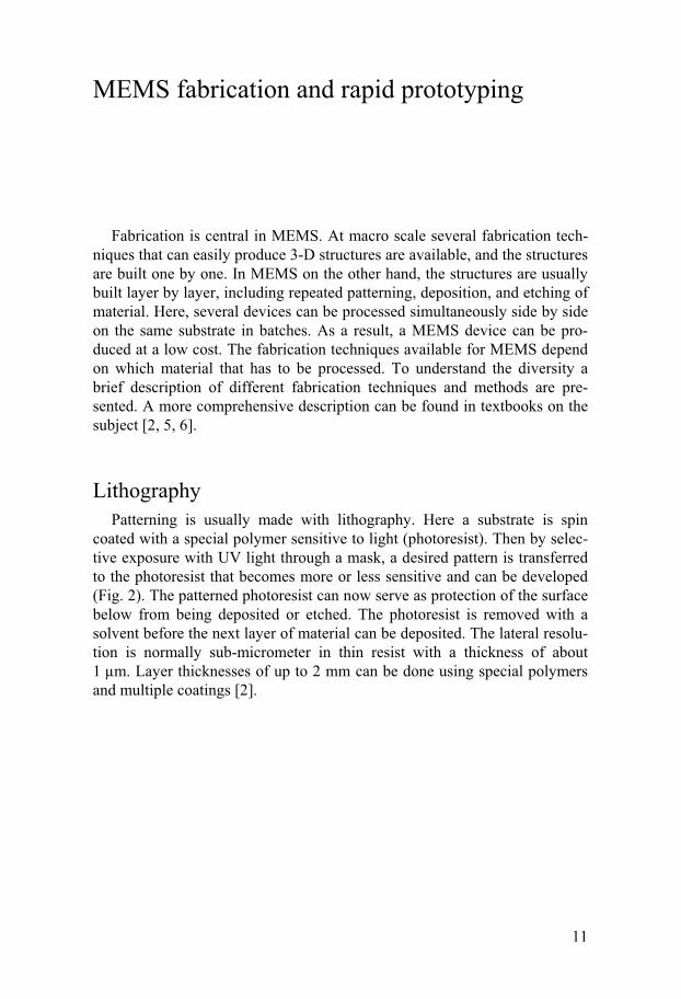
Liquid polymerization A way to create millimeter thick structures is to use e.g. liquid resin of
UV curable epoxy. Instead of spin coating photoresist as in ordinary lithog-raphy, a one-component epoxy that is poured into a mould can be used. So-lidification, patterning, and curing takes place in one single step (Fig. 4) and the structures are complete with a short post-cure after the uncured epoxy is rinsed. This method does not require as long curing steps compared to thick photoresist.
14
Figure 4. Solidification, patterning, and curing with UV-light from two sides (a), removed, rinsed, and post-cured structure (b).
Liquid photopolymerization has been used as a rapid prototyping tech-nique in Paper II and IV, using overhead transparencies with resolution of 1200 dpi as masks and a 400 W metal halide lamp as the UV source.
Milling and drilling As polymers are becoming more frequently used in MEMS, milling and
drilling are interesting. For example, a commercial prototype milling ma-chine for printed circuit boards (PCB) [8] is sufficient in many cases. The resolution is a few micrometers and commercial tool diameters of down to 100 μm are available. Milling is useful for fabrication of few components, drilling of holes for fluidic connection, or to create masters that can be used with polymer replication techniques. Milling is also useful for rapid proto-typing.
Rapid prototyping and rapid fabrication Prototyping includes development techniques where preliminary versions
(prototypes) of a system, or part of a system, are built to investigate its feasi-bility, and reducing the risk. Rapid prototyping can be used to test unknown characteristics of components or systems by fabrication techniques where the time from idea to realized device is short. Milling and soft lithography can be considered as rapid fabrication techniques.

15
Paraffin wax
What is paraffin wax? The word paraffin (para-, -finum) means lacking affinity or lacking reac-
tivity, and paraffin does not easily mix with polar fluids as water. Paraffin wax is a mixture of saturated alkanes, hydrocarbons, with the general for-mula CnH2n+2. Alkanes can either be straight or branched, i.e. normal or iso-meric (Fig. 5). The simplest alkane is the gas methane, CH4, and the first isomeric alkane is isobutane (CH3)3CH. The isomeric possibilities increase with the number of carbon atoms and there exists about 4 billion combina-tions of C30H72 [9].
Figure 5. An illustration of linear normal (n-) and branched isomeric (iso-) alkanes, where each free end-site is represented by a hydrogen atom.
Paraffin is commonly used in products such as skin lotion, protective sur-faces for food, window openers in green houses, and for thermostats in cars.
Depending on the refinement process, some paraffin waxes usually con-tain few wt-% of oil. However, refined paraffin waxes that can be used in the food industry, contain only 0.4-0.8 wt-% oil, are colorless, and do not con-tain any substances that are harmful to health [10].

16
Material properties Paraffin waxes change their volume at phase transitions and are by defini-
tion solid at room temperature. The phase change of paraffin is reversible, and the heat that is needed to change phase, e.g. melting, is stored in the material as latent heat and is returned when the material crystallizes. The melt temperature for n-alkanes, and thus paraffin waxes, are connected to the chain length of the n-alkane. However, the highest melt temperature con-verge to about 140°C for very long chains e.g. polyethylene (Fig. 6). A fluid can, however, be supercooled and will then not start to crystallize at the same temperature as where the melting ends. The critical limit for supercool-ing for alkanes between C16-C34 is about 95% of their coagulating point, meaning that they will spontaneously start to crystallize 10-15°C below that point [11]. But in practice this temperature is only a few degrees below the coagulation point.
Figure 6. Melting temperature as a function of number of carbon atoms.
When a melt of paraffin starts to coagulate, the molecules will pack close together in ordered form, i.e. they will start to crystallize. Consequently the more ordered solid phase has a higher density and a decrease in volume is seen (Fig. 7). Similar to metals, n-alkanes crystallize in different configura-tions (lattices). There are four known ways for n-alkanes to crystallize, namely (hexagonal (�H), orthorhombic (�O), monoclinic (�M), and triclinic (�T); each with their own shape and size. Thus, volume changes can also be observed for solid-to-solid transitions as well.

17
Figure 7. The volume changes with phase change such as melting when the material goes from crystalline to amorphous.
It is the thermo mechanical properties that make paraffin interesting in MEMS. C36, for instance, has a free volume expansion of about 22% when heating it from 30 to 80°C, and its compressibility at liquid phase is less than 1% per 10 MPa [12]. Further, the coefficient of thermal expansion (CTE) is roughly 500 ppm/K for solid C36, which is few times more compared to many polymers, and more than 10 times greater compared to metals.
If two alkanes are mixed at different ratios, numerous combinations of
these configurations can be achieved. Consequently, by choosing suitable alkanes and mix ratio, more or less stepwise expansions could be utilized including solid-to-solid transitions. It is even possible to achieve an eutectic point, where the melting temperature is lower than the melting point for the two components (Fig. 8).

18
Figure 8. Example of a phase diagram of binary mixtures, Cn and Cm.
Analysis methods Most studies on paraffin wax and n-alkanes have been made for better
understanding of the crystallization behavior of other polymers [11, 13], or for studying their thermal heat-storage properties.
Differential scanning calorimetry (DSC) can be used to attain information such as transition temperatures and enthalpies for a material. However, this method does not provide any thermo mechanical information. In addition, a dilatometer that records the linear expansion as function of temperature and pressure can be used. With this, so called pressure-volume-temperature (pVT), equipment information about for the coefficient of thermal expansion (CTE) and volume expansions at phase changes can be attained.
pVT are somewhat time consuming in the sample preparation step, and the sample sizes are about 100 times larger than for DSC. The DSC can also be loaded with several samples and can be run automatically.
Binary mixtures of n-alkanes (Paper I) In Paper I binary mixtures of n-alkanes are investigated by means of pVT
and DSC. The mixing behavior is studied and a comparison between the two methods is made.

19
Figure 9. Enthalpy as a function of temperature as obtained with DSC (Paper I).
Figure 10. Volume expansion and applied pressure as a function of temperature as obtained with pVT (Paper I).
The result from pVT and DSC can be seen in Figs. 9 and 10. A good pre-diction of the volume expansion at phase transitions can be made with DSC, but to attain a more exact volume expansion, a pVT measurement is needed. The pressure dependency on the melting temperature is found to be about 0.3 KMPa-1.
It was found that the temperature width of the intermediate phase indeed could indeed be manipulated by mixing the alkanes.
20
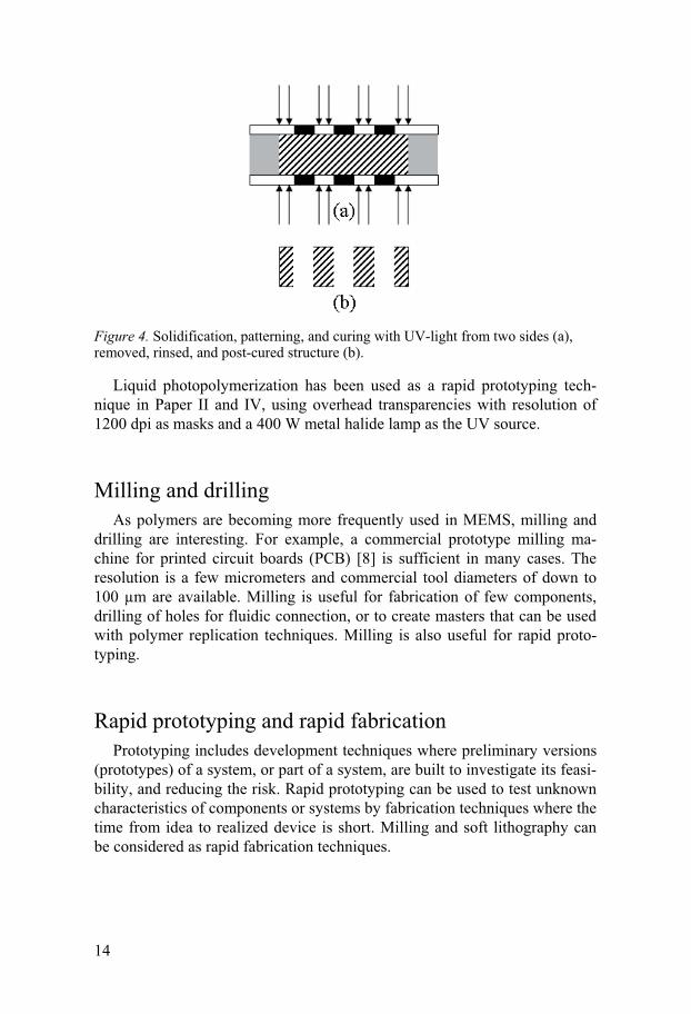
pVT dilatometry on a paraffin wax (Paper II) In Paper II, the volume expansion of the paraffin wax (Sigma-Aldrich,
76228) is measured with pVT. The wax is also used in Paper III-VI. It is found that a solid-to-solid transition with volume expansion of more than 2% is present between 20-30°C, and an expansion of less than 6% was observed for the solid-to-liquid transition (Fig. 11). The linear volume expansion be-tween 30-46°C is about 2%, and the overall volume expansion from ambient temperature of 20°C to melt is 10%.
Figure 11. Volume expansion of paraffin wax (Sigma-Aldrich, 76228) as obtained with pVT. The wax has a melting point at 46°C and solid phase transition between 20-30°C, (Paper II).

21
Paraffin wax actuators
An actuator can be described as a transformer that can convert e.g. an electrical signal into mechanical work. There are several existing microac-tuators in which different techniques as magnetic, piezoelectric, thermal expansion, phase change, and electrostatic actuation are used. A simple way to compare these is by their physical properties such as force, displacement, and speed [14].
But compared to microsensors, microactuators have not yet easily been adopted to commercial products. One reason for this is their disadvantage when scaled down and most actuators can simply not produce sufficient force or displacements at microscale. For example an actuator that uses the popular piezoelectric effect can create large forces but not large displace-ments. Shape memory alloys (SMA) that use solid phase transitions can produce both large expansions and large forces. However, these are com-monly formed to springs and wires and are less suited for microfabrication techniques. On the other hand, there are successful examples too. The elec-trostatic force is well suited in RF-MEMS and optical MEMS as in the DMD chip [1].
Thermopneumatics and thermohydraulics are attractive methods to use because they can produce large displacements, high forces, and can be miniaturized. These are well suited for e.g. microfluidics. Wax actuators are especially interesting as they can produce large forces along with large vol-ume expansion. Many fabrication techniques, designs, and materials can be used as well.
A survey on paraffin actuators In MEMS, no commercial device is yet available with paraffin wax as the
actuator material. However, in research the term microactuator used for par-affin actuators is mentioned in work from 1997 [15, 16]. These actuators are several centimeters long and the word micro refers to the possible displace-ments. One sub-centimeter long piston actuator capable of producing forces of 10 N is presented in [17].
A microactuator built with surface micromachining on silicon and glass substrates [18] uses a 9 μm thick paraffin layer with diameter of 400-800 μm and is covered with parylene as diaphragm. The deflections are about 3 μm,

22
and the glass substrate actuator has a power consumption of 100-150 mW with response times of 30-50 ms. The power consumption for the silicon substrates is up to 3 W, but with response times 10 times smaller than for the glass substrate.
A Braille cell with paraffin wax is presented in [19] using three layers of bulk micromachined silicon and a silicone rubber diaphragm. The device is filled with paraffin by placing it on a hot plate and molten paraffin is poured into the wax containers. The diaphragm rubber is applied by brushing it over the device. The approximate diaphragm thickness is 80 μm and the diameter is 1.5 mm. The maximum dot height is 654 μm for 8 V input voltage.
A thermal switch for thermal control meant to be used in a nanosatellite [20] use the excess heat in the satellite to melt paraffin wax to close a switch enabling heat transfer. The device is made with bulk micromachining in silicon and at the last step the paraffin is filled into the cavity using a sy-ringe. The device is able of producing movements of about 75 μm with 3 N load.
Another paraffin based actuator to be used in a nanosatellite propulsion system is presented in [21]. Here the paraffin was filled in the same fashion as in injection molding. The actuators are heated with attached heaters. The filling is seen as a major problem, as it is difficult to control.
Polymeric actuators with hot-embossed structures and thermally bonded or glued membrane are presented in [22, 23]. The general approach here is to enhance the bonding properties by surface treatments, or developing the glue process. Extensive rupture load tests are made to study the joining properties of the membranes to the bulk. Other paraffin actuators can also be found in [24-26].
Rapid prototyping of a paraffin actuator (Paper II) In Paper II a membrane paraffin actuator is made by means of rapid pro-
totyping using liquid photopolymerization. The aim is to investigate both the usefulness of the process and the performance of the actuator by changing the input potential and frequency of a square wave over several cycles. The ability to integrate a heater into the paraffin volume is studied as well as with the use of an adhesive tape as a membrane. Deflection measurements are made using a contact probe with a high load of 0.5 N in contact pressure.
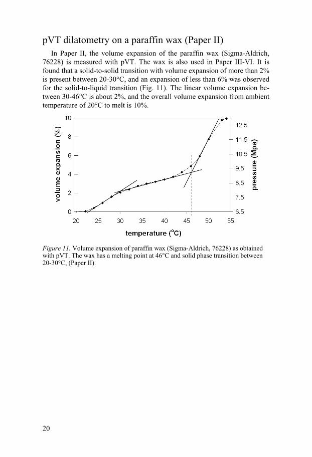
The tests indicate a degeneration of the actuator that is run over 1,050 cy-
cles. This degeneration is a result of paraffin leakage under the tape mem-brane. The actuator had a maximum deflection of 90 μm measured with a white light interferometer. It is found that a steady state behavior is present when the actuator is run at higher frequencies, and an offset of the curve can
23
be seen (Fig. 12). The reason for this is that the cooling is not efficient enough.
Figure 12. Deflection behavior for an actuator at 0.5 Hz and 0.71 V.
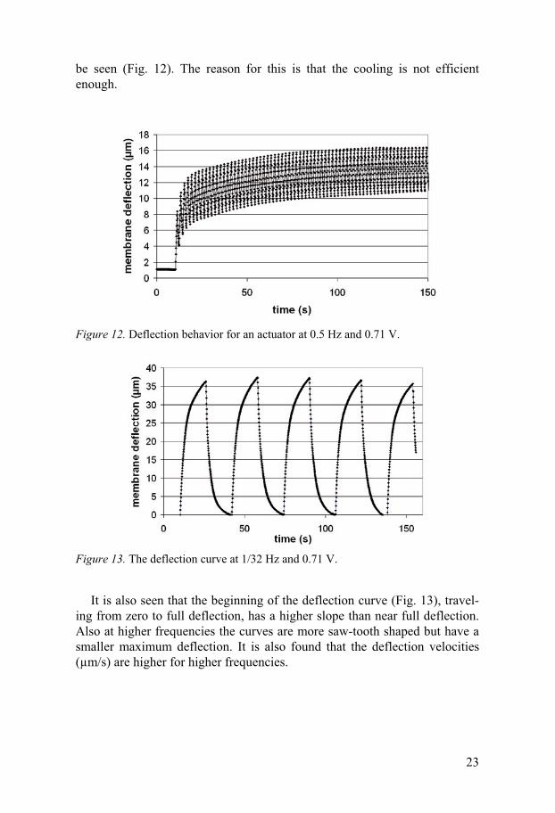
Figure 13. The deflection curve at 1/32 Hz and 0.71 V.
It is also seen that the beginning of the deflection curve (Fig. 13), travel-
ing from zero to full deflection, has a higher slope than near full deflection. Also at higher frequencies the curves are more saw-tooth shaped but have a smaller maximum deflection. It is also found that the deflection velocities (μm/s) are higher for higher frequencies.

24
A multi-stable paraffin actuator with local active deflection (Paper III)
The aim in Paper III is to investigate the possibility to create multi-stable positions and local deformation for a membrane paraffin actuator by using multiple heaters. Milling and gluing are used to build the actuators.
Figure 14. Schematic description of multi-stable positioning. (a) solid paraffin, (b) liquid paraffin, (c) the paraffin is allowed to crystallize in part of the cavity by selec-tive heating, and (d) solid paraffin with deformed membrane.
The poor thermal heat transfer between liquid and solid state is utilized in such a way that both solid and liquid phases can co-exist within the same cavity. This is made by the use of several heaters that are individually con-trolled to create thermal gradients in the paraffin (Figs. 14 and 15).
Figure 15. An actuator used in active mode where part of the paraffin is melted and creates a local deflection of the membrane (b), (a) is a non-activated actuator.
The actuators, run in their simplest way, are capable of multi-stable posi-tioning with the number of stable positions depending on how many heater

25
elements that are used. The difference between the lowest and highest points on a membrane is typically 40-100 μm, and the slope between these peaks and pits have angles of up to 5° (Fig. 16). In addition, the paraffin could also be melted locally over a heater as earlier described.
Figure 16. Actuator that is run in diagonal mode with an elevated ridge (2) diagonal across the membrane and lower pits (1).

26

27
Microfluidics
The analytical performance of chemical sensing can be improved by miniaturizing fluidic systems as diffusion lengths decrease. Scaling is also beneficial in the sense that less sample volumes and reagents are needed. This has led to an impressive development of the field of microfluidics, also called Lab-on-a-chip, Bio-MEMS, or μTAS, over the last decade [27].
The miniaturization towards μTAS has open new possibilities for portable systems that can e.g. be used for point-of-care tests (POCT) where the pa-tient their self introduces samples as saliva, blood, or urine to the microflu-idic chip. In remote settings, maybe diseases as HIV can be detected only by introducing a drop of blood on site without the need of a central laboratory or skilled personnel [28].
The further away from a central laboratory with skilled personnel, the more functions have to be integrated to the chip. For instance, depending on sample, different pre-treatments such as filtration, washing, and rinsing are needed [29]. If a μTAS should be able of carrying this out, several reservoirs containing reagents and fluids are needed on the chip. These fluids have to be pumped one by one, and valves have to be used to control the direction of flow. The fluids have to be loaded and stored on-chip, and cross contamina-tion has to be avoided. Moreover, it is an advantage that the valves and pumps are small, inexpensive, easy to drive, and perhaps disposable if they are located on the chip.
Miniaturised valves and pumps are associated with many difficulties, and commercialization has been delayed by the lack of reliable components [30]. When downsizing a fluidic channel, the pressure needed to drive a flow in it increases due to an increased surface-to-volume ratio. As a consequence, the pumps and valves are not capable of producing sufficient pressures. How-ever, there are many pumps that are able of producing sufficient flow rates of ml/min, but for low flow rates of less then fractions of μl/min many diffi-culties arise [31, 32].
Valves Valves are mainly divided into active and passive ones. Active valves
utilize an actuator for operation. The actuator can move parts to seal an ori-fice or be used as throttle in a channel. Passive valves have structures that

28
are designed to have a higher flow resistance in one direction than the other. A passive valve can also be done by means of capillary valves by drastically changing the geometry, or by increasing the flow resistance locally within the channel using hydrophobic zones. The performance of a valve is re-stricted by (1) the sealing properties against the valve seat, and (2) the ability to generate a force from the actuator or the passive structure (i.e. geometry or material properties). A good seal can be achieved by a large sealing area, and can be enhanced by choosing a soft material in one part of the valve [32]. For example, when used in a pump, the leakage and maximum pressure that a valve can work against will often define the performance of the pump.
Paraffin wax is interesting in valves as it has the ability of producing high forces. For that reason paraffin wax has been used in active valves [33-34]. Even if one could expect high pressures of these valves, higher pressures than 160 kPa [35] have not been reported before. However, where paraffin has been used as latch in combination with external actuators [36-38], pres-sures between 275 kPa and 1,725 kPa are shown.
A normally open active valve (Paper IV) As part of the work presented in Paper IV where a polymeric paraffin
pump is made, an active valve is evaluated using different types of mechani-cal clamping.
The valve was built using a paraffin actuator (Paper II). A channel struc-ture built on a glass slide with valve seat and fluidic channels is glued to the actuator and fluidic connectors are then glued onto the chip. By activating the actuator, the membrane rises and seals against an inlet, and the valve opens when the actuator is switched off (Fig. 17).
Rubber tubes and silicone glue did not give enough support for the glass substrate that was ruptured at pressures of 200 kPa. A stiff port enhanced the robustness, and the valve sustained pressures op to 350 kPa. Finally, the port is clamped with a spring clamp, and impressive pressures of 0.9 MPa were achieved at an input power of about 0.3W without any visible leakage.

29
Figure 17. Schematic of the valve with the inlet (1) and valve seat (2) perpendicular to the membrane of the actuator (3), channel substrate (4), and the outlet (5).
Passive valves In Paper V and VI, passive valves are described to be used in contact with
reservoirs. The valves should be able to hold pressures greater than the flow resistance in the outside channels to prevent contamination. They should also prevent backflow of fluid into the reservoirs after the reservoirs have been emptied. The valves are built of PDMS plugs that are cast or glued into drilled holes in polystyrene. The lid is glued against a channel substrate with valve seat. The function of the valves is described in Fig. 18.
Figure 18. Function of the passive valve that opens for an applied pressure (left) and seals against the valve seat for a negative pressure (right).
Different valve designs are tested with respect to opening pressure (Fig. 19). Designs A-C (Paper V) are glued to the valve seat and Design D (Paper VI) are mechanically clamped.

30
Figure 19. Comparison between valves with adhesive boning in interface design A-C (Paper V) and mechanically clamped valves, design D (Paper VI).
Micropumps and injectors Basically a micropump can be designed from one pumping chamber and
two valves. By choosing passive valves and one pumping chamber, a recip-rocating pump is achieved. The performance of such a pump is associated with the ability to continuously provide a transfer of energy to the continu-ously flowing fluid. These pumps are usually fitted with a piezoelectric driver that is driven with frequencies up to kHz. Even though flow rates of up to ml/min are reported, the maximum pressures of these pumps are nor-mally about tens of kPa up to few hundered kPa. Small flow rates and non-continuous flow can be somewhat difficult to achieve due to leakage in the valves [31, 32].
Using at least three or more active valves, a peristaltic pump can be real-ized. The peristaltic pump squeezes the fluid forward, and the performance of the pump is highly associated with the performance of its valves [31].
In some cases it can be more useful to use a single stroke to inject a fluid into a channel or chamber. Basically, if the peristaltic pump is dimensioned with a large pumping chamber, it can be used as injector and the whole, or part, of a stroke volume can be used.
A peristaltic pump (Paper IV) A peristaltic pump (Fig. 20) is fabricated and tested in Paper IV. The
pump is made in the same way as the active valve earlier described. The

31
overall size of the pump, excluding the out and inlets is 25×10×2 mm3. Ex-cluding the flexible printed circuits, the size is even smaller (12×6×2 mm3).
Figure 20. A paraffin micropump with rubber tubing located over the inlet and out-let valves at the backside of chip.
Figure 21. Pumped volume as function of time for the micropump.
The pump was tested using a square wave of period 28.8 s and heater ef-fect of 0.2 W gave 74 nl/min in average flow rate (Fig. 21). The pump was tested for 30 minutes that corresponds to about 60 cycles. The valves, as described earlier, are capable of sustaining pressures up to 0.9 MPa.
Injection pump and a fluid interface (Paper V) In Paper V a concept for using paraffin wax in direct contact with a fluid
for injection is presented. The pump has a reservoir partly filled with paraf-fin and the rest with a fluid. The paraffin is filled during fabrication, and the fluid is filled via the rubber part of the passive valve (Fig. 22) using a sy-ringe needle. The passive valve opens when the pressure is high enough, and the fluid is moved from the reservoir to a nearby channel. The paraffin will create a negative pressure in the reservoir as it starts to crystallize and the valve will close. A developed concept of this injector is described in Paper VI.

32
Figure 22. Schematic description of a septum for filling a fluid into a reservoir using a syringe needle that penetrates the soft rubber material.
Lab-on-a-chip (Paper V and VI) In Paper VI the concept presented in Paper V is taken a step further and is
integrated to a microfluidic chip. This 55×40×4 mm3 sized chip contains three individual fluidic reservoirs, paraffin actuators with integrated heaters, a fluidic channel that can serve as reaction chamber, passive valves, fluidic interface (septum) for loading of fluids to reservoirs, a sample inlet, and a waste (Fig. 23). The chip is designed to carry out sequential flow in less than 5 minutes, with a reaction chamber volume of 10 μl, total channel volume of 15 μl and, reagent volumes of 20 μl. Air bubbles are introduced to improve the rinsing function. Sequential flow is shown to work with three different coloured fluids and an air bubbles (Fig. 24).
Figure 23. A concept layout for the chip (left) and a real device seen without cover lid (right).

33
Figure 24. From above (left to right) a channel filled with colored fluid is rinsed with colorless fluid. A green fluid is then rinsed through the channel, and in the last row, a colorless fluid rinse the channel.

34

35
Future perspectives
Without doubt, paraffin has the ability to be used in many MEMS appli-cations in the future. On the other hand, how long it will take to reach a com-mercial MEMS market is an open question. However, a commercial product would be important for the research community to increase the focus on paraffin wax.
Rapid prototyping techniques were used throughout this thesis. This ap-proach has often allowed fabrication of complex devices within a week and has given useful information in the development process of these compo-nents. For instance, the tape membrane can be used over a thousand cycles with a useful deflection. Also the valve performance can be enhanced by mechanical clamping instead of a stronger adhesive bond. However, these rapid prototyping techniques should be taken for what they are, namely a tool to quickly investigate properties and performances of a device but not for production precise structures or of large series at low costs. Hence, those paraffin actuator concepts that have potential of a larger societal interest should be transferred into devices produced with techniques more commonly used in MST or fine mechanics. Still, these devices made by rapid prototyp-ing techniques quickly give answers that can be used for further develop-ment of a device or concept at several levels.
The most important factor to enhance the speed of these actuators is fur-ther miniaturization. But does size matter? Paraffin wax actuators have al-ready many other advantages that compensate for speed and therefore find-ing applications where speed is not critical is maybe more important than maximizing speed. Nevertheless, it would be interesting to examine the limit for miniaturizing a paraffin actuator that is made by means of rapid fabrica-tion using milling in PCB.
For the engineer who designs these actuators in future it would perhaps be useful to know how to choose the right paraffin. Moreover a simple model for how the paraffin actuator will respond to different inputs by choosing different heaters, dimensions of paraffin cavity, materials, and heat-sinks, is important. This could be provided by researchers. The devices need to be tested in more severe environment conditions. How well does a paraffin wax component work after being cycled in the military standard temperature range of -40 to 120°C? Of course, it is needed to test paraffin actuators to the standards of the application fields of interest. Finally, my opinion is that now these actuators have reached a point when they would gain more if effort

36
was put in other areas than process development and proof-of-concepts. For example, the drive and control have to be developed and integrated, and the need of closed-loops has to be investigated.

37
Conclusion
Beside the large forces and large volume expansions of paraffin wax in miniaturized actuators, the low cost of paraffin in combination with a simple activation principle, is attractive. Further, the low voltage drive is very inter-esting for portable systems. The possibilities to modify paraffin to have more or less solid transitions are interesting, and the possibility to choose different melt temperatures for a paraffin wax are also attractive.
As shown in this work, paraffin wax can be fitted into many different components and systems, exploring it in different ways. Paraffin is well suited for high pressure microfluidics, sustaining pressures of almost 1 MPa in an active valve, and is not the limiting factor in achieving larger pressures. Paraffin can also be used in peristaltic pumps and in direct contact with a fluid in injectors. A multi-stable actuator is also made without extra me-chanical parts, using several heaters to control the thermal gradients within the paraffin cavity. This actuator can be interesting to use in many systems where energy can be saved by using a latched actuator. In addition, active control added new dimension to the usefulness of paraffin actuators.

38

39
Summary in Swedish
MEMS (mikroelektromekaniska system), från några mikrometer till cen-timeterstora, börjar bli en del av vår vardag och används exempelvis som sensorer i bilar, mikrospeglar i HDTV och som skrivhuvuden i bläckstråle-skrivare, för att nämna några. Fördelen med MEMS och miniatyrisering är flera. Dels så finns möjligheten att sänka produktionskostnader för enskilda komponenter med satsvis tillverkning, eller att sensorer blir känsligare och effektivare i mikroskala. Inom bioteknik har miniatyrisering av vätskekana-ler visat sig öka effektiviteten vid analyser, men andra effekter är att mindre mängder av vätskor behövs för att göra en analys. Man pratar då om Lab-on-a-chip och micro-total-analysis systems eller microfluidik.
Miniatyriseringen inom området mirofluidik ger även möjligheter till att utföra diagnostiska hälsotester nära patienten, point-of-care. Med dessa tes-ter kan man upptäcka sjukdomar eller sjukdomstillstånd som indikeras av till exempel höga halter av vissa ämnen i blod, urin eller saliv. Vinsten är att patienten själv skulle kunna utföra testet på liknande sätt som diabetessjuka idag testar sina blodvärden.
Tillförlitliga komponenter som ventiler och pumpar behövs i dessa chip men på mikroskala är detta svårt av flera anledningar. Ofta behöver man en motor (aktuator) som driver dessa pumpar och ventiler, men när man mins-kar skalan kommer förflyttingar och krafter att minska. I värsta fall orkar aktuatorerna inte av att hålla emot de tryck som uppkommer i miniatyrisera-de system. Utöver de fysiska aspekterna så spelar kostnaden för material och tillverkning stor roll för vilken aktuator som kommer att väljas. Idag finns det inget entydigt svar på vilken typ av aktuator som är bäst lämpad. Detta skiljer sig från fall till fall. Mer forskning krävs alltså för att hitta lämpliga aktuatorer som är effektiva men också relativt billiga.
Detta arbete fokuserar på paraffin som aktuatormaterial i miniatyriserade aktuatorer. Paraffin har visat sig vara intressant i mikrosystem på grund av dess stora volymexpansioner och förmåga att producera stora krafter. Eter-som man traditionellt sett arbetar med kisel i MEMS, för att bygga sina strukturer, har tidigare paraffinaktuatorer främst varit kiselbaserade. Men, inom området mikrofluidik har man insett att det finns många fördelar med polymera strukturer. En anledning är att tillverkningsmetoderna för dessa är enklare och snabbare jämfört med traditionell kiselprocessning. Komponen-terna i detta arbete är därför framtagna med tillverkningsmetoder som är
40
lämpade för plaster. Dessa metoder är dock mest lämpade för att snabbt ta fram komponenter (prototyper) för att visa fungerande koncept.
I papper I studeras hur man kan blanda två rena paraffiner (n-alkaner) och
erhålla en stegvis expansion med varierande storlek beroende på grad av blandning. Utvärderingen är gjord med två olika metoder; en där man stude-rar entalpi (värmeupptagning) i materialet och den andra där man studerar volymexpansionen.
I papper II tillverkas en polymerbaserad paraffinaktuator med integrerade värmare i paraffinet och som membran användes en tejp av polyimid. Resul-tatet visade att aktuatorn trots kunde köras över tusen cykler med användbara förflyttningar mot en i sammanhanget hög punktlast.
Tidigare presenterade paraffinaktuatorer kräver kontinuerlig tillförsel av energi för att hålla en given utböjning. I papper III undersöks om paraffinet självt går att använda till att låsa utböjningar i olika positioner. Genom att använda sig av flera lateralt placerade värmare kan man lokalt smälta paraf-fin och styra stelning varvid flera stabila positioner går att uppnå. Denna funktion är viktig i system där man vill bibehålla en position men samtidigt spara på energi.
I papper IV byggs en peristaltisk pump som klämmer fram vätska med hjälp av två ventiler och en pumpkammare. Aktuatorerna som används är identiska med de presenterade i papper II. Denna för tillfället unika mikro-pump med paraffin som aktivt material har ventiler som klarar upp till 0.9 MPa mottryck utan synligt läckage, vilket är mycket högt.
Papper V och VI visar koncept som är tänkta att kunna användas i portab-la Lab-on-chip. Här behandlas frågeställningar och koncept visas för förva-ring av reagenser på chip, fyllning av dessa vätskor genom ett interface, för-flyttning av vätskorna från dess behållare till intilliggande kanalsystem med hjälp av integrerade paraffinpumpar och passiva ventiler.
Slutsatsen är att paraffin är ett aktuatormaterial som har flera fördelar
lämpliga i mikrosystem. Inte minst har detta visats för tillämpningar inom mikrofluidik med höga tryck och innovativa lösningar med Lab-on-chip som tillämpningsexempel. Paraffin är dessutom väl anpassat till att användas med tillverkningstekniker ämnade för rapid prototyping och rapid fabrication i polymera material. Den slutgiltiga bedömningen är att paraffin mycket väl kommer att passa i kommersiella produkter med MEMS-komponenter i framtiden. Kanske som en låsbar aktuator då det börjar bli allt viktigare med energibesparing i många produkter.

41
Acknowledgements
If there was a God I would probably thank him first. However, as it is, I’d like to thank Jan-Åke Schweitz for introducing me to the wonderful world of paraffin wax, Klas Hjort for his visionary talks and support, and Greger Thornell for interesting discussions.
I would like, in particular, to thank Roger Bodén, the second (or first) half of the ‘dream team paraffin’…
I also want to thank Stefan Johansson fascinating chats and fishing trips. All the mates at μ-meck are acknowledged: Hanna Yousef, Niklas Snis, Sara Thorslund, Axel Lundvall, Erik Edqvist, Linda Johansson, and all ex-PhD students (and perhaps the diploma workers as well…and all the new ones that ‘sneaks in’ without warning from their supervisors).
Moreover, I’d like to thank ‘Tribosarna’ including the senior people for dwelling in front of the aquatic zoo at coffee break. Especially acknowl-edged are Sture ‘Professor’ Hogmark, Lars Hammerström-Häggkvist, Daniel H. E. Persson, and Nils ‘Telefunken U-47’ Stavlid.
Carin Palm, Jan-Åke Gustafsson, Rein Kalm, Caroline, Anette, Anja Hohmann, Ingrid Ringård, Jonatan Bagge, and everybody else at ‘Materi-alvetenskap’ are acknowledged as well.
Maria, My (μ), and Kajsa, I love you!
Frank Zappa and Mike Keneally To all my friends and families... Luv! Marcus Lehto Uppsala 2007-08-13

42
43
References
1. www.dlp.com 2007-08-05 2. M. J. Madou Fudamentals of microfabrication 2nd ed. CRC Press (2002) 3. www.radi.se 2007-08-05 4. www.wtc-consult.de 2007-08-05 5. S. D. Senturia Microsystems Design Kluwer Academic Publishers (2001) 6. N. Maluf An introduction to Microelectromechanical Systems—, Micro-
electromechanical systems Artech House, Inc. (2002) 7. Y. Xia and G. M. Whitesides, Soft lithography, Angewandte Chemie
International Edition, 37, (1998), 551-575 8. www.solectro.se 2007-08-05 9. Nationalencyklopedin, Bra Böcker AB, (1989), Höganäs 10. M. Freund, R. Csikós, S. Keszthelyi, and G. Y. Mózes, Paraffin products
- Properties, technologies, applications, Elsevier, (1982), New-York 11. W. R. Turner, Normal Alkanes, Industrial and Engineering Chemistry
Product Research and Development, 10, (1971), 238-260 12. P. Zoller and D. J. Walsh Standard pressure-volume-temperature data for
polymers, Technomic, (1995), Lancaster 13. M. Dirand, M. Bouroukba, V. Chevallier, and D. Petitjean, Normal al-
kanes, multialkane synthetic model mixtures, and real petroleum waxes: Crystallographic structures, thermodynamic properties, and crystalliza-tion, Journal of Chemical and Engineering Data, 47, (2002) 115-143
14. D. J. Bell, T. J. Lu, N. A. Fleck, and S. M. Spearing, MEMS actuators and sensors: observations on their performance and selection for pur-pose, Journal of Micromechanics and Microengineering, 15, (2005) S153-S164
15. N. Kabei, et al., A Thermal-Expansion-Type Microactuator with paraffin as the Expansive Material, JSME International Journal, Series C, 40, (1997) 736-742
16. D. E. Dowen, Design and implementation of paraffin based microposi-tioning actuator, Proceedings of the SPIE - The International Society for Optical Engineering, v 3132, (1997), 127-134
17. R. Bodén, M. Lehto, and J.-Å. Schweitz, A Paraffin driven linear micro-actuator for high force and large displacement applications, Actuator 2006, 10th International Conference on New Actuators, June 2006, Bre-men, 720-723
18. E. T. Carlén and C. H. Mastrangelo, Electrothermally activated paraffin microactuators Journal of Microelectromechanical Systems, 11, (2002), 165-174
19. J. S. Lee and S. Lucyszyn, A micromachined refreshable Braille cell, Journal of Microlectromechanical Systems, 14, (2005), 673-682
44
20. L. Klintberg, M. Karlsson, L. Stenmark, J.-Å. Schweitz, and G. Thornell, A large stroke, high force paraffin phase transition actuator, Sensors and Actuators A, 96, (2002) 189-195
21. L. Klintberg, M. Karlsson, L. Stenmark, and G. Thornell, A thermally activated-paraffin based actuator for gas-low control in a satellite elec-trical propulsion system, Sensors and Actuators A, 105, (2003), 237-246
22. L. Klintberg, M. Svedberg, F. Nikolajeff, and G. Thornell, Fabrication of a paraffin actuator using hot embossing of polycarbonate, Sensors and Actuators A, 103, (2003), 307-316
23. M. Svedberg, F. Nikolajeff, and G. Thornell, On the integration of flexi-ble circuit boards with hot embossed thermoplastic structures for actua-tor purposes, Sensors and Actuators A, 125, (2006), 534-47
24. L. Klintberg and G. Thornell, A thermal microactuator made by partial impregnation of polyimide with paraffin, Journal of Micromechanics and Microengineering, 12, (2002), 849-54
25. P. Dubois, E. Vela, S. Koster, D. Briand, H. R. Shea, and N.-F. de Rooij, Paraffin-PDMS composite thermo microactuator with large vertical dis-placement capability, Actuator 2006, 10th International Conference on New Actuators, Bremen, 215-218
26. J. S. Lee and S. Lucyszyn, Design and pressure analysis for bulk-micromachined electrothermal hydraulic microactuators using a PCM, Sensors and Actuators A, 133, (2007), 294-300
27. D. R. Reyes, D. Iossifidis, P.-A. Auroux, and A. Manz, Micro total analysis systems. 1. Introduction, theory, and technology, Analytical Chemistry, 74, (2002), 2623-2636
28. C. D. Chin, V. Linder, and S. K. Sia, Lab-on-chip for global health: Past studies and future opportunities, Lab Chip, 7, (2007), 41-57
29. A. de Mello and N. Beard, Dealing with ‘real’ samples: sample pre-treatment in microfluidic systems, Lab Chip, 3, (2003), 11N-19N
30. K. W. Oh and C. H. Ahn, A Review of microvalves, Journal of Microme-chanicics and Microengineering, 16, (2006), R13-R39
31. D. J. Laser and J. G. Santiago, A Review of Micropumps, Journal of Mi-cromechanis and Microengineering, 14, (2004), R35-R64
32. N.-T. Nguyen and S.T. Wereley Fundamentals and Applications of Mi-crofluidics, Artech House, Inc., (2002), London
33. E. T. Carlén and C. H. Mastrangelo, Paraffin-actuated surface micro-machined valves, Journal of Microelectromechanical Systems, 11, (2002), 408-420
34. T. Kobayashi, S. Matsuoka, A. Ueno, and R. Maeda, An Easy Fabrica-tion Technique for Micro Paraffin Actuator and Application to Mi-crovalve, Electrochemical Society Proceedings, 9, (2004) 330
35. P. Selvaganapathy, E. T. Carlén, and C. H. Mastrangelo, Electrother-mally actuated inline microfluidic valve, Sensors and Actuators A, 104 (2003), 275-282
36. R. H. Liu, J. Bonanno, J. Yang, R. Lenigk, and P. Grodzinski, Single-use, thermally actuated paraffin valves for microfluidic applications, Sensors and Actuators B, 98, (2004) 328-336
37. R. Pal, M. Yang, B. N. Johnson, D. T. Burke, and M. A. Burns, Phase change microvalve for integrated devices, Analytical Chemistry, 76, (2004) 3740-3748
38. K. W. Oh, K. Namkoong, and C. Park, A phase change microvalve using a metable magnetic material: Ferro Wax, Proc. of μTAS (2005) Boston


Acta Universitatis UpsaliensisDigital Comprehensive Summaries of Uppsala Dissertationsfrom the Faculty of Science and Technology 325
Editor: The Dean of the Faculty of Science and Technology
A doctoral dissertation from the Faculty of Science andTechnology, Uppsala University, is usually a summary of anumber of papers. A few copies of the complete dissertationare kept at major Swedish research libraries, while thesummary alone is distributed internationally through theseries Digital Comprehensive Summaries of UppsalaDissertations from the Faculty of Science and Technology.(Prior to January, 2005, the series was published under thetitle “Comprehensive Summaries of Uppsala Dissertationsfrom the Faculty of Science and Technology”.)
Distribution: publications.uu.seurn:nbn:se:uu:diva-8165
ACTAUNIVERSITATIS
UPSALIENSISUPPSALA
2007