pakistan engineering council - 2021 - naphda
TRANSCRIPT

Standardization of Building Codes, Standards
and Specifications for Low-Cost (Affordable) Units
Pakistan Engineering Council - 2021

ii
Standardization of Building Codes, Standards
and Specifications for Low-Cost (Affordable)Units
Pakistan Engineering Council, Islamabad
First Edition - Copyright ® 2021

iii
PREFACE
Pakistan like most developing countries, is facing an acute shortage of housing. It is estimated that
the annual demand for housing units is approximately 700,000 a year, whereas, only about half of this
demand is met. On the whole, the housing deficit is estimated between 10 to 12 million units and is
growing every year. To address the situation, Prime Minister of Pakistan envisioned and initiated Naya
Pakistan Housing Program (NPHP) “to deliver five million housing units with allied amenities to all
citizens, especially focusing on the financially underserved and middle-income communities, as a
measure of comprehensive socio-economic uplift”. The program would provide housing facility to
the homeless people by accelerating the economic activity and also provides job opportunities to a
large extent in the country. Naya Pakistan Housing & Development Authority (NAPHDA) being a
corporation was established on 15th January 2020 through an Act of Parliament for the purpose of
planning, development, construction, and management of real estate development schemes and
projects including housing. The Authority being the developing arm of the government is pursuing
multiple objectives in the realm of housing and infrastructure development on both profit and non-
profit basis throughout the country.
NAPHDA is very much committed to ensure quality assurance in the housing sector development
projects especially in the Low-Cost Housing Units. For this purpose, NAPHDA has joined hands with
the Pakistan Engineering Council (PEC) for the development of Standards Specifications for
Low-Cost (Affordable) Units. Accordingly, PEC notified a high profile “Working Group for
Standardization of Building Codes, Standards, and Specifications for Low-Cost (Affordable)
Units” on 14th December 2020 which comprised the following eminent experts:
1. Engr. Prof. Dr. Sarosh Hashmat Lodi Convener
Vice Chancellor, NED University of Engineering and Technology, Karachi.
2. Engr. Brig. Abid Saleem Member
Executive Director (Monitoring) NAPHDA, Islamabad.
3. Arc. Plnr. Kalim Siddiqui Member
Chairman, Pakistan Council of Architects and Town Planners, Lahore
4. Chair Prof. Engr. Dr. Shuaib H. Ahmad Member
Head CAHSBE, NED University of Engineering and Technology, Karachi
5. Engr. Prof. Dr. Muhammad Ali Memon Member
Associate Professor Prof. Deptt. of Electrical Engineering, NED, Karachi
6. Engr. Zaigham Mahmood Rizvi Member
Chairman, Naya Pakistan Housing Program

iv
7. Mr. Fayyaz Ilyas Member
Chairman, Association of Builders and Developers of Pakistan (ABAD), Karachi
8. Dr. Engr. Fawad Ahmed Najam
Assistant Prof. Department of Structural Engineering, NUST, Islamabad Member
9. Engr. Danish Bin Rauf Member
Chairman Southern Region, ABAD, Karachi
10. Arc. Hammad Husain Member
President League of Architects Pakistan, Islamabad
11. Arc. Azar Raza Khan Member
Principal Architect, Azar Raza Architects, Islamabad
12. Engr. Faiz Muhammad Bhutta Member
Sr. Energy Consultant and CEO Techfa Consulting, Lahore
13. Mr. Faiz ul Sibtain Secretary to Committee
Think Tank Department, Pakistan Engineering Council, Islamabad.
The Committee held four meetings and successfully developed “Standardization of Building Codes,
Standards, and Specifications for Low-Cost (Affordable) Units”. The Committee performed
extraordinary hard work and completed this task within six weeks. The Convener highly appreciated
the contribution of the members and significant work of the “Editorial Committee”. This document is
based on well-recognized standards and best practices developed by national and international reputed
codes developing organizations.
The feedback/ comments sought from the Provincials Departments were deliberated and the relevant
inputs have been included in the document by the experts “Working Group”.

v
Preface ................................................................................................................................................. iii
SECTION 1 GENERAL ITEMS .......................................................................................................... 1
1.1 Definition .............................................................................................................................. 1
1.2 Purpose ................................................................................................................................. 1
1.3 Applicability ......................................................................................................................... 1
1.4 Interpretation ......................................................................................................................... 1
1.5 Licensed design professional ................................................................................................ 1
1.6 Authority Having Jurisdiction .............................................................................................. 1
1.7 The Engineer ......................................................................................................................... 1
1.8 Building Official ................................................................................................................... 1
1.9 Quality of Units (Houses or Homes) .................................................................................... 1
1.10 Materials ............................................................................................................................... 2
1.11 Approval of Materials, Products or Systems ........................................................................ 2
1.12 Construction Practice ............................................................................................................ 2
SECTION 2 EXCAVATION ............................................................................................................... 3
1. Scope......................................................................................................................................... 3
2. Clearing and Grubbing-Up ....................................................................................................... 3
3. Excavation ................................................................................................................................ 3
SECTION 3 PLAIN AND REINFORCED CONCRETE .................................................................... 7
1. Scope......................................................................................................................................... 7
2. General ...................................................................................................................................... 7
3. Related Specifications............................................................................................................... 7
4. Materials ................................................................................................................................. 10
5. Concrete .................................................................................................................................. 15
6. Tests for Concrete Quality ...................................................................................................... 23
7. Finishing of Formed Concrete ................................................................................................ 24
8. Repair of Surface Defects ....................................................................................................... 27
9. Concrete Construction Tolerance ........................................................................................... 28
10. Plant and Equipment ........................................................................................................... 30
11. Acceptance of Structure ...................................................................................................... 33
SECTION 4 MASONRY ................................................................................................................... 40
Part-I ............................................................................................................................................... 40
1. Concrete Block Masonry ........................................................................................................ 40
1.1 Scope................................................................................................................................... 40
1.2 Materials ............................................................................................................................. 40
1.3 Concrete, Masonry Units .................................................................................................... 40
1.4 Cement Mortar for Masonry ............................................................................................... 41

vi
1.5 Masonry and Jointing ......................................................................................................... 41
1.6 Coordination ....................................................................................................................... 43
1.7 Protection and Cleaning ...................................................................................................... 43
1.8 Samples ............................................................................................................................... 43
1.9 Testing ................................................................................................................................ 43
1.10 Measurement and Payment ................................................................................................. 43
SECTION 4 MASONRY ................................................................................................................... 44
Part-II .............................................................................................................................................. 44
1. Brick Masonry .................................................................................................................... 44
1.1 Scope................................................................................................................................... 44
1.2. Codes and Standards ........................................................................................................... 44
1.3. Submittals ........................................................................................................................... 44
1.4 Tolerances ........................................................................................................................... 44
1.5. Inspection and Testing ........................................................................................................ 45
1.6. Delivery and Storage .......................................................................................................... 45
1.7. Mortar ................................................................................................................................. 46
1.8. Bricks .................................................................................................................................. 47
1.9. Scaffolding .......................................................................................................................... 47
1.10. Execution ........................................................................................................................ 48
1.11. Repairing Brickwork ....................................................................................................... 49
1.12. Horizontal Damp Proof Course ...................................................................................... 49
1.13. Vertical Damp Proof Course ........................................................................................... 49
1.14. Measurement and Payment ............................................................................................. 49
SECTION 5 CARPENTRY AND JOINERY .................................................................................... 51
1. Scope of Work ........................................................................................................................ 51
2. Submittals ............................................................................................................................... 51
3. Applicable Standards .............................................................................................................. 51
4. Tolerances ............................................................................................................................... 52
5. Delivery and Storage .............................................................................................................. 52
6. Products .................................................................................................................................. 52
7. Execution ................................................................................................................................ 55
8. Measurement and Payment ..................................................................................................... 57
SECTION-6 TERRAZZO WORK ..................................................................................................... 58
1. Scope of Work ........................................................................................................................ 58
2. Applicable Standard ................................................................................................................ 58
3. Materials ................................................................................................................................. 58
4. Samples ................................................................................................................................... 58
5. Execution ................................................................................................................................ 59

vii
6. Measurements and Payments .................................................................................................. 60
SECTION-7 CERAMIC TILES ......................................................................................................... 62
Part 1 - General ............................................................................................................................... 62
1. Section Includes .................................................................................................................. 62
2 Submittals ............................................................................................................................... 62
3 Quality Assurance ................................................................................................................... 64
4. Mockups ................................................................................................................................. 64
5 Delivery, Storage, and Handling ............................................................................................. 64
Part 2 - Products.............................................................................................................................. 65
1. Products General ..................................................................................................................... 65
2. Floor Tiling ............................................................................................................................ 66
4. Glass Mosaics ........................................................................................................................ 69
5. Tile Fittings ............................................................................................................................ 69
6. Stone Thresholds .................................................................................................................... 69
7. Setting and Grouting Materials .............................................................................................. 69
8. Elastomeric Sealants .............................................................................................................. 71
9. Miscellaneous Materials ........................................................................................................ 71
10. Metal Accessories .............................................................................................................. 71
Part 3 - Execution ........................................................................................................................... 72
1 Examination ................................................................................................................................. 72
2. Preparation ............................................................................................................................. 73
3 Installation, General ............................................................................................................... 73
4. Ceramic Tile Floor Installation Schedule .............................................................................. 74
5. Ceramic Tile Wall Installation Schedule ............................................................................... 75
6. Glass Mosaic Installation Schedule ....................................................................................... 76
7. Cleaning and Protecting ......................................................................................................... 76
SECTION 8 PLASTER AND POINTER ........................................................................................... 77
1. Scope of Work ........................................................................................................................ 77
2. Applicable Standards .............................................................................................................. 77
3. General .................................................................................................................................... 77
4. Materials ................................................................................................................................. 77
5. Proportioning and Mixing ....................................................................................................... 79
6. Preparation of Surface to Be Plastered ................................................................................... 79
7. Application of Plaster ............................................................................................................. 79
8. Metal Lath over Reinforced Concrete and Masonry Joint ...................................................... 80
9. Beads & Profiles ..................................................................................................................... 80
10. Cleaning and Protection ...................................................................................................... 80
11. Tolerances ........................................................................................................................... 80

viii
12. Pointing Work ..................................................................................................................... 81
13. Measurement and Payment ................................................................................................. 81
SECTION-9 INTERIOR PAINTING ................................................................................................. 83
Part 1 - General ............................................................................................................................... 83
1. Section Includes ..................................................................................................................... 83
2. Submittals .............................................................................................................................. 83
3. Quality Assurance .................................................................................................................. 84
4. Preconstruction Testing ......................................................................................................... 85
5. Mockups ................................................................................................................................ 86
6. Delivery, Storage, and Handling ............................................................................................ 86
7. Project Conditions ................................................................................................................. 86
Part 2 - Products.............................................................................................................................. 87
1. Manufacturers ........................................................................................................................ 87
2 Paint General ......................................................................................................................... 87
3. Health and Environmental Requirements ............................................................................... 87
4. Interior Primers ....................................................................................................................... 88
5. Interior Fillers and Putties...................................................................................................... 89
6. Acrylic Emulsion for Cement Based Surfaces ....................................................................... 89
7. Epoxy Paint for Cement Based Surfaces ............................................................................... 90
8. Polyurethane Paint for Cement Based Surfaces..................................................................... 91
9. Acrylic Emulsion Paint for Gypsum Boards and Cement Boards ......................................... 91
10. Opaque Finish of Wood Surfaces ...................................................................................... 91
11. Ferrous Surfaces Finish Paint System (Architectural Work Items) ................................... 91
12. Traffic-Related Paints ........................................................................................................ 92
Part 3 - Execution ........................................................................................................................... 92
1. Examination ........................................................................................................................... 92
2. Preparation ............................................................................................................................. 93
3. Application ............................................................................................................................ 94
4. Field Quality Control ............................................................................................................. 96
5. Cleaning and Protection ......................................................................................................... 96
6. Interior Painting Schedule ..................................................................................................... 96
Exterior Painting ................................................................................................................................. 99
1. Crete Sand Coating ..................................................................................................................... 99
2. Surface Preparation .................................................................................................................... 99
3. Technical Data / Specification .................................................................................................... 99
SECTION-10 GLAZING ................................................................................................................. 101
1. Scope of Work ...................................................................................................................... 101
2. Applicable Standards ............................................................................................................ 101

ix
3. General .................................................................................................................................. 101
4. Delivery Storage and Handling ............................................................................................. 101
5. Materials ............................................................................................................................... 101
6. Installation of Glazing .......................................................................................................... 103
7. Protection and Cleaning Of Glazing ..................................................................................... 103
8. Measurement and Payment ................................................................................................... 103
SECTION 11 ROOF WATER PROOFING SYSTEM .................................................................... 104
1. Scope of Works ..................................................................................................................... 104
2. Material ................................................................................................................................. 104
3. Samples ................................................................................................................................. 105
4. Protection .............................................................................................................................. 105
5. Measurement ......................................................................................................................... 105
6. Rate and Payment ................................................................................................................. 105
SECTION-12 ALUMINIUM WINDOWS ....................................................................................... 106
Part 1 - General ............................................................................................................................. 106
1.1 Sections Includes .............................................................................................................. 106
1.2 Performance Requirements ............................................................................................... 106
1.4 Quality Assurance ............................................................................................................. 107
1.5 Project Conditions ............................................................................................................ 107
1.6 Warranty ........................................................................................................................... 108
Part 2 - Products............................................................................................................................ 108
2.1 Manufacturers ................................................................................................................... 108
2.2 Materials ........................................................................................................................... 108
2.3 Framing Systems .............................................................................................................. 108
2.4 Glazing .............................................................................................................................. 109
2.5 Insect Screens ................................................................................................................... 109
2.6 Hardware ........................................................................................................................... 110
2.7 Accessory Materials .......................................................................................................... 110
2.8 Fabrication ........................................................................................................................ 110
2.9 Aluminum Finish .............................................................................................................. 111
Part 3 - Execution ......................................................................................................................... 111
3.1 Examination ...................................................................................................................... 111
3.2 Installation ........................................................................................................................ 111
3.3 Adjusting, Cleaning, and Protection ................................................................................. 112
SECTION-13 TERMITE CONTROL .............................................................................................. 113
Part 1 - General ............................................................................................................................. 113
1.1 Section Includes ................................................................................................................ 113
1.2 Performance Requirements ............................................................................................... 113

x
1.3 Submittals ......................................................................................................................... 113
1.4 Project Conditions ............................................................................................................ 114
1.5 Coordination ..................................................................................................................... 114
1.6 Warranty ........................................................................................................................... 114
1.7 Maintenance Service ......................................................................................................... 114
Part 2 - Products............................................................................................................................ 114
2.1 Manufacturers ................................................................................................................... 114
2.2 Soil Treatment .................................................................................................................. 114
Part 3 - Execution ......................................................................................................................... 115
3.1 Examination ...................................................................................................................... 115
3.2 Preparation ........................................................................................................................ 115
3.4 Applying Soil Treatment .................................................................................................. 115
SECTION-14 CAR PARK CURBS AND WALKWAYS ............................................................... 117
Part 1 - Genera .............................................................................................................................. 117
1.1 Section Includes ...................................................................................................................... 117
1.2 Submittals ........................................................................................................................ 117
1.3 Quality Assurance ............................................................................................................ 117
Part 2 - Products............................................................................................................................ 117
2.1 Formwork ......................................................................................................................... 117
2.2 Reinforcement ................................................................................................................... 117
2.3 Cast-In-Place Concrete ..................................................................................................... 117
2.4 Curing ............................................................................................................................... 117
2.5 Sealant Filled Joints .......................................................................................................... 117
2.6 Ancillary Materials ........................................................................................................... 118
2.7 Mix Designs ...................................................................................................................... 118
Part 3 - Execution ......................................................................................................................... 118
3.1 Execution, General ........................................................................................................... 118
3.2 Curbs and Walkways ........................................................................................................ 118
SECTION-15 EXPANSION JOINT COVER ASSEMBLIES ......................................................... 119
Part 1 - General ............................................................................................................................. 119
1.1 Section Includes ................................................................................................................ 119
1.2 Performance Requirements and Selection Criteria ................................................................. 119
1.3 Submittals ......................................................................................................................... 119
1.4 Quality Assurance ............................................................................................................. 120
1.5 Coordination .................................................................................................................... 120
1.6 Warranty ........................................................................................................................... 120
Part 2 - Products............................................................................................................................ 121
2.1 Materials ........................................................................................................................... 121

xi
2.2 Architectural Joint Systems, General ................................................................................ 121
2.3 Architectural Joint Systems, General ................................................................................ 122
Part 3 - Execution ......................................................................................................................... 123
3.1 Examination ............................................................................................................................ 123
3.2 Preparation .............................................................................................................................. 123
3.3 Installation .............................................................................................................................. 123
SECTION-16 PLUMBING WORKS ............................................................................................... 125
Section 16 Part 1 ........................................................................................................................... 125
1. Scope of Work ...................................................................................................................... 125
1.1 System Description ........................................................................................................... 125
1.2 Schedule of Materials and Equipment .............................................................................. 127
Section 16 Part 2 ........................................................................................................................... 128
2. Underground and Draining system. ....................................................................................... 128
2.1 General .............................................................................................................................. 128
2.2 Installation ........................................................................................................................ 128
2.5 Inspection Chambers (Manhole) ....................................................................................... 129
2.6 Concrete Sumps ................................................................................................................ 129
2.7 Pipe Sleeves ...................................................................................................................... 129
2.8 Tests .................................................................................................................................. 129
Section 16 Part 3 ........................................................................................................................... 130
3. Internal Sanitary System ........................................................................................................... 130
3.1 Piping Installation ............................................................................................................. 130
3.2 Pipes Gradient ................................................................................................................... 130
3.3 Pipe Size ........................................................................................................................... 130
3.4 Traps ................................................................................................................................. 131
3.5 Grating and Cover for Floor Trap and Waste ................................................................... 131
Section 16 Part 4 ........................................................................................................................... 132
4. Installation of Sanitary Appliances ....................................................................................... 132
4.1 Water Closet ..................................................................................................................... 132
4.2 Flushing Cisterns .............................................................................................................. 132
4.3 Bath Tub ........................................................................................................................... 132
4.4 Shower Mixer ................................................................................................................... 132
4.5 Waste Sanitary Appliances ............................................................................................... 132
4.6 Grab Bars: ......................................................................................................................... 133
4.7 Surgical Scrub sinks .......................................................................................................... 133
4.8 Shower Seat ...................................................................................................................... 134
4.9 Plumbing Fittings and Accessories ................................................................................... 134
Section16 Part 5 ............................................................................................................................ 135

xii
Cold and Hot Water Supply .......................................................................................................... 135
5.1 General .............................................................................................................................. 135
5.2 Water Service Connection ................................................................................................ 135
5.3 Piping Materials ................................................................................................................ 135
4.4 Piping Joints ...................................................................................................................... 135
5.5 Pipe Supports .................................................................................................................... 135
5.6 Testing of Main ................................................................................................................. 136
5.7 Sterilization of Main ......................................................................................................... 136
5.8 Valves ............................................................................................................................... 136
5.9 Schedule of Valves ........................................................................................................... 136
5.10 Trap ................................................................................................................................... 137
5.11 Testing of Pipelines .......................................................................................................... 137
5.12 Pipe Insulation (sound proofing) ...................................................................................... 137
Pipe Work and Fittings ................................................................................................................. 138
Section 16 Part 6 ........................................................................................................................... 138
6 Pipe work and Fitting ............................................................................................................ 138
6.1 General .............................................................................................................................. 138
6.2 Pipe Joints ......................................................................................................................... 138
6.3 Pipe Supports .................................................................................................................... 138
6.4 Pipe Sleeves ...................................................................................................................... 139
6.5 Pipe Work installation ...................................................................................................... 139
6.6 Valves ............................................................................................................................... 139
FIRE FIGHTING SYSTEM ............................................................................................................. 143
Section 16 Part 7 ........................................................................................................................... 143
7. Pipe work and Fitting ............................................................................................................ 143
7.1 General .............................................................................................................................. 143
7.2 Pipe Materials ................................................................................................................... 143
7.3 Pipe Supports .................................................................................................................... 143
7.4 Pipe Sleeves ...................................................................................................................... 144
7.5 Pipe Work installation ...................................................................................................... 144
7.6 Valves ............................................................................................................................... 144
7.7 Hose Reel Cabinet ............................................................................................................ 144
7.8 Fire Hydrant (4-1/2’’ Main Valve) ................................................................................... 144
7.9 Breeching inlet .................................................................................................................. 145
7.10 Landing Valve .................................................................................................................. 145
7.11 Fire Extinguishers ............................................................................................................. 145
PLUMBING EQUIPMENT .............................................................................................................. 146
Section 16 Part 8 ........................................................................................................................... 146
xiii
Equipment and Controls ............................................................................................................... 146
8.1 Water Transfer Pump ........................................................................................................ 146
8.2 Firefighting Pump ............................................................................................................. 146
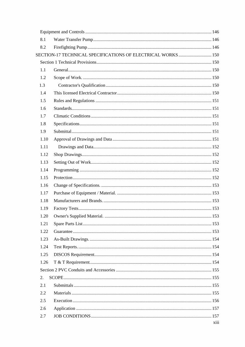
SECTION-17 TECHNICAL SPECIFICATIONS OF ELECTRICAL WORKS ............................. 150
Section 1 Technical Provisions ..................................................................................................... 150
1.1 General .............................................................................................................................. 150
1.2 Scope of Work. ................................................................................................................. 150
1.3 Contractor's Qualification ............................................................................................. 150
1.4 This licensed Electrical Contractor ................................................................................... 150
1.5 Rules and Regulations ...................................................................................................... 151
1.6 Standards........................................................................................................................... 151
1.7 Climatic Conditions .......................................................................................................... 151
1.8 Specifications .................................................................................................................... 151
1.9 Submittal ........................................................................................................................... 151
1.10 Approval of Drawings and Data ....................................................................................... 151
1.11 Drawings and Data........................................................................................................ 152
1.12 Shop Drawings .................................................................................................................. 152
1.13 Setting Out of Work .......................................................................................................... 152
1.14 Programming .................................................................................................................... 152
1.15 Protection .......................................................................................................................... 152
1.16 Change of Specifications. ................................................................................................. 153
1.17 Purchase of Equipment / Material. ................................................................................... 153
1.18 Manufacturers and Brands. ............................................................................................... 153
1.19 Factory Tests ..................................................................................................................... 153
1.20 Owner's Supplied Material. .............................................................................................. 153
1.21 Spare Parts List ................................................................................................................. 153
1.22 Guarantee .......................................................................................................................... 153
1.23 As-Built Drawings. ........................................................................................................... 154
1.24 Test Reports. ..................................................................................................................... 154
1.25 DISCOS Requirement....................................................................................................... 154
1.26 T & T Requirement. .......................................................................................................... 154
Section 2 PVC Conduits and Accessories .................................................................................... 155
2. SCOPE .................................................................................................................................. 155
2.1 Submittals ......................................................................................................................... 155
2.2 Materials ........................................................................................................................... 155
2.5 Execution .......................................................................................................................... 156
2.6 Application ....................................................................................................................... 157
2.7 JOB CONDITIONS .......................................................................................................... 157

xiv
Section -3 Wires, Cables and Cords ............................................................................................. 158
3.1 Scope ...................................................................................................................................... 158
3.2 Materials ................................................................................................................................. 158
Section -4 Wiring Accessories ...................................................................................................... 160
4.1 Scope................................................................................................................................. 160
4.2 Submittals ......................................................................................................................... 160
4.3 Materials ........................................................................................................................... 160
4.4 Execution .......................................................................................................................... 160
4.5 Dandification .................................................................................................................... 161
4.6 Quality Assurance ............................................................................................................. 161
Section -5 Point Wiring, Circuit Wiring and Socket Outlet Wiring ............................................. 162
5.1 Scope................................................................................................................................. 162
5.2 Materials ........................................................................................................................... 162
Section -6 Light Fixtures .............................................................................................................. 163
6.1 Scope................................................................................................................................. 163
6.2 Submittals ......................................................................................................................... 163
6.3 Materials ........................................................................................................................... 164
6.4 Execution ........................................................................................................................ 165
6.5 Quality Assurance ............................................................................................................. 165
6.6 Extra Materials .................................................................................................................. 165
Section -7 Power Cable ................................................................................................................ 167
7.1 Scope................................................................................................................................. 167
7.2 Submittals ......................................................................................................................... 167
7.3 Materials ........................................................................................................................... 167
7.4 Delivery, Storage and Handling ........................................................................................ 169
7.5 Execution .......................................................................................................................... 169
7.6 Quality Assurance ............................................................................................................. 170
Section -8 Main L.T. Switch Board .............................................................................................. 171
8.1 Scope................................................................................................................................. 171
8.2 Submittals ......................................................................................................................... 171
8.3 Wiring Diagrams: Power, signal, and control wiring. ...................................................... 171
8.4 Materials ........................................................................................................................... 172
8.5 Delivery, Storage, and Handling ...................................................................................... 172
8.6 Execution .......................................................................................................................... 172
8.6 Project Conditions ............................................................................................................ 173
8.7 Quality Assurance ............................................................................................................. 173
8.8 Adjusting........................................................................................................................... 174
8.9 Protection .......................................................................................................................... 174

xv
Section -9 Distribution Boards ..................................................................................................... 175
9.1 Scope................................................................................................................................. 175
9.2 Submittals ......................................................................................................................... 175
9.3 Materials ........................................................................................................................... 176
9.4 Execution .......................................................................................................................... 177
Section -10 Earthing ..................................................................................................................... 178
10.1 Scope................................................................................................................................. 178
10.2 Submittals ......................................................................................................................... 178
10.3 Materials ....................................................................................................................... 178
10.4 Execution ...................................................................................................................... 179
10.5 Quality Control ............................................................................................................. 179
Section -11 Testing and Commissioning ...................................................................................... 180
11.1 Scope................................................................................................................................. 180
11.2 Type of Tests ................................................................................................................ 180
Section 18 STEEL WORKS ....................................................................................................... 183
1. Scope of Work ...................................................................................................................... 183
2. Submittals ............................................................................................................................. 183
3. Applicable Standards ............................................................................................................ 183
4. Quality Assurance ................................................................................................................. 184
5. Materials ............................................................................................................................... 184
6. Execution .............................................................................................................................. 187
7. Delivery and Storage ............................................................................................................ 191
8. Measurement and Payment ................................................................................................... 192
SECTION 19 ENVIRONMENTAL IMPACT ASSESSMENT ...................................................... 193
a. Environmental Impact Assessment (EIA) ............................................................................ 193
b. The EIA Process ................................................................................................................... 193
c. Steps involved in conducting an EIA included the following: ............................................. 193
SECTION 20 QUALITY ASSURANCE CRITERIA AND GUIDELINES FOR PREFABRICATED
UNITS .............................................................................................................................................. 199
2. Component- and Structural-Level Tests for Prefabricated Units .......................................... 200
a. Structural Integrity and Strength ........................................................................................... 200
b. Energy Efficiency ................................................................................................................. 200
c. Seismic Resilience ................................................................................................................ 200
d. Specifications for Component- and Structural-Level Tests of Prefabricated Units .............. 201
SECTION 21 GUIDELINES FOR SOLAR PV SYSTEM .............................................................. 202
1. Solar PV System for Single Story House – Suitable for Five Marla and 10 Marla Single Phase
Connected House .......................................................................................................................... 203
2. BOQ Proposed for 3 KVA Grid Hybrid System is as under, ............................................... 204

xvi
3. For Multiple Story Flats and Apartments ............................................................................. 206
4. Prepaid Metering For 3 Marla and Less Houses and Flats – Solar not recommended – NON
MANDATORY ............................................................................................................................ 207
APPENDIX-A .................................................................................................................................. 208
SPECIFICATIONS FOR STRUCTURAL PRECAST CONCRETE .............................................. 208
APPENDIX-B................................................................................................................................... 227
HOLLOW & LIGHT GAUGE STEEL SECTIONS (HSS & LGS)-SPECIFICATIONS ............... 227

1
SECTION 1 GENERAL ITEMS
1.1 Definition
According to State bank of Pakistan in consultation with stake holders defines the low-cost housing
as follows:
a. Covered area of the housing unit / apartment up to 850 square feet,
b. Maximum value of the housing unit/apartment up to PKR 3.5 million,
c. Loan size up to PKR 3.15 million.
1.2 Purpose
The purpose of this specification document is to provide for public health and safety by
establishing minimum requirements for strength, serviceability, durability and integrity of
affordable low cost units to be built in Pakistan.
1.3 Applicability
This specification document shall apply to affordable low cost units to be built in Pakistan
under the requirements of the Building Code of Pakistan or the code adopted Authority Having
Jurisdiction (AHJ). If no general building code is adopted, this document shall apply for the
construction of the affordable housing units.
1.4 Interpretation
If conflicts occur between clauses of this document and those of standards and documents
referenced in the beginning of individual sections of this document shall govern.
1.5 Licensed design professional
All references in this Code to the licensed design professional (LDP) shall be understood to
mean the person who is licensed and responsible for, and in charge of, the
Architectural/Structural design or inspection. For Architectural and Town Planning work,
PCATP and for Engineering works PEC registered and licensed professional will be
considered respectively.
1.6 Authority Having Jurisdiction
Authority Having Jurisdiction (AHJ) means an organization, office, or individual responsible
for enforcing the requirements of a code or standard, or for approving equipment, materials,
an installation, or a procedure.
1.7 The Engineer
The Engineer or Engineer of Record means a professional engineer who seals drawings,
reports, or documents for a project. The seal shall acknowledge that the professional engineer
prepared, coordinated, or had subordinates prepare under the direct supervision of the
professional engineer, drawings, reports, or documents for a project.
1.8 Building Official
The officer or other designated authority charged with the administration and enforcement of
this Specification.
1.9 Quality of Units (Houses or Homes)
a. The standard of construction shall be adequate for a minimum service life of twenty five
(25) to forty (40) years.
b. Where materials or methods are not clearly defined in the project documents, the engineer
shall assess contractor submittals for adequacy to required standards of construction
c. Written submittal shall be provided to the Licensed Design Professional or the Engineer

2
for all materials, products or systems for his approval. No material, product or system
shall be used until written approval is given by the Engineer.
1.10 Materials
a. The Contractor shall adhere strictly to all standard specifications, Codes of Practice,
Building Regulations or similar which are referred to in the Contract Documents. If no
standard is specified then the relevant IBC Standard will be deemed to apply, but the
Engineer may at his discretion accept materials in accordance with other standards
specifications if the quality is equivalent or superior to the Referenced Standards.
b. The Contractor shall fully demonstrate in detail supported by written documentation that
he has investigated all local manufactures of all products and materials listed in this
specifications.
c. Preference must be given to Pakistani produced materials and products. In the event that
the correct quality or cost margins are not met these shall be brought to attention of the
Employer prior to rejection. The Employer reserves the right to direct Contractors to
purchase locally produced materials rather than overseas materials where all other factors
are equal.
d. All overseas material manufactures shall comply with ISO 9000 requirements.
e. The abbreviations used in the document include:
A.S.T.M - American Society for Testing and Materials.
ACI – American Concrete Institute
AISC – American Institute of Steel Construction
AISI - American Iron And Steel Institute
ASCE – American Society of Civil Engineers
BS – British Standards
BCP – Building Code of Pakistan
I.S.O - International Standards Organization.
IBC – International Building Code
IRC – International Residential Code
PSQCA - Pakistan Standards and Quality Control Authority
The standard applicable shall be the standard most recent date of publication. In addition
Referenced standards are also listed in the individual sections of this document.
1.11 Approval of Materials, Products or Systems
a. Approval of materials, products or systems in accordance with clause 1.1(c) shall not, in
any way, relieve the Contractor of full responsibility under the contract.
b. Approval of materials, products or systems not included in these specifications may be
submitted for approval to the Authority Having Jurisdiction (AHJ) for evaluation and
possible Approvals.
c. For the certain materials and components which are specified on the Drawings using
proprietary names, the Contractor may submit details of any alternative which meets the
said standard and quality to the Authority Having Jurisdiction (AHJ) for evaluation and
possible written approval.
1.12 Construction Practice
This document contains coverage for what is conventional and common in residential
construction practice. While the document aims to provide needed coverage for most
residential construction, it might not address construction practices and systems that are
atypical or rarely encountered in the industry.

3
SECTION 2 EXCAVATION
1. Scope
The work covered by this section of the specification consists in furnishing all plant, labour,
equipment, appliances and materials, and in performing all operations in connection with
excavation, trenching and backfilling, in strict accordance with this section of specification
and the applicable drawings, and subject to the terms and conditions of the CONTRACT.
2. Clearing and Grubbing-Up
The sites of all excavation shall be cleared of all shrubs, plants, bushes, large roots and other
surface materials. All such materials shall be removed and disposed of in a manner satisfactory
to the SITE ENGINEER. All trees and shrubbery that are designated by the SITE ENGINEER
to remain shall be adequately protected and preserved in an approved manner.
3. Excavation
All excavation, in any kind of soil encountered, shall be performed to the depths and widths
indicated or as otherwise specified. This would vary with local site conditions. During
excavation, material suitable for backfilling shall be stockpiled in an orderly manner at a
sufficient distance from the banks of the excavation to avoid overloading and to prevent sides
from caving. Topsoil shall be stockpiled separately, for subsequent re-use as necessary. All
excavated material unsuitable or not required for backfilling shall be removed and collected
at a location approved by the SITE ENGINEER. Grading shall be done as may be necessary
to prevent surface water from flowing into trenches or other excavations, and any water
accumulated therein shall be removed by pumping or by other approved methods. Unless
otherwise indicated or approved by the SITE ENGINEER, excavation shall be open cut.
It is anticipated that all excavation work under this CONTRACT, will be earth excavation.
The term “earth” as used herein shall include all materials which do not in the opinion of the
SITE ENGINEER, require blasting, barring or wedging of material for removal from its
original bed.
The CONTRACTOR shall provide adequate timbering or sheeting for excavation where
necessary, as part of the excavation work, to hold up the sides and ends of all excavations.
Should the sides and ends of any excavation give away, the CONTRACTOR shall, at no extra
cost to the EMPLOYER reinstate all disturbed ground. Any excavation carried beyond the
limits shown on the drawings and specified herein as the payment limits, shall be treated as
excess excavation and dealt with in the manner stated hereinafter.
When foundation level is reached, the SITE ENGINEER will inspect the exposed bottom and
give directions as to what further excavation, if any, he considers necessary. The excavation
shall be done in such a manner as to ensure that the work rests on a solid and perfectly clean
foundation. Where excavation is to be covered subsequently by permanent construction, the
CONTRACTOR shall, immediately after exposing the specified satisfactory foundation
proceed with the construction on that foundation. If the CONTRACTOR allows any portion
of such foundation to deteriorate due to exposure, he shall make good the foundations at no
extra cost to the EMPLOYER and to the satisfaction of the SITE ENGINEER.
4. As part of the work, under the excavation items, the CONTRACTOR shall shore up all
buildings, walls poles and other structures, the stability of which is liable to be endangered by
the execution of the work and shall be fully responsible for all damages to life or property
resulting from any default of the CONTRACTOR.
4
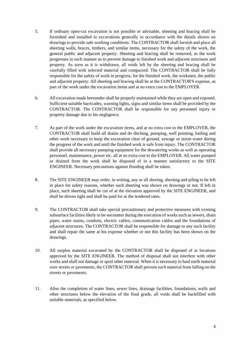
5. If ordinary open-cut excavation is not possible or advisable, sheeting and bracing shall be
furnished and installed in excavations generally in accordance with the details shown on
drawings to provide safe working conditions. The CONTRACTOR shall furnish and place all
sheeting walls, braces, timbers, and similar items, necessary for the safety of the work, the
general public and adjacent property. Sheeting and bracing shall be removed, as the work
progresses in such manner as to prevent damage to finished work and adjacent structures and
property. As soon as it is withdrawn, all voids left by the sheeting and bracing shall be
carefully filled with selected material and compacted. The CONTRACTOR shall be fully
responsible for the safety of work in progress, for the finished work, the workmen, the public
and adjacent property. All sheeting and bracing shall be at the CONTRACTOR'S expense, as
part of the work under the excavation items and at no extra cost to the EMPLOYER.
6. All excavation made hereunder shall be properly maintained while they are open and exposed.
Sufficient suitable barricades, warning lights, signs and similar items shall be provided by the
CONTRACTOR. The CONTRACTOR shall be responsible for any personnel injury or
property damage due to his negligence.
7. As part of the work under the excavation items, and at no extra cost to the EMPLOYER, the
CONTRACTOR shall build all drains and do ditching, pumping, well pointing, bailing and
other work necessary to keep the excavation clear of ground, sewage or storm water during
the progress of the work and until the finished work is safe from injury. The CONTRACTOR
shall provide all necessary pumping equipment for the dewatering works as well as operating
personnel, maintenance, power etc. all at no extra cost to the EMPLOYER. All water pumped
or drained from the work shall be disposed of in a manner satisfactory to the SITE
ENGINEER. Necessary precautions against flooding shall be taken.
8. The SITE ENGINEER may order, in writing, any or all shoring, sheeting and piling to be left
in place for safety reasons, whether such sheeting was shown on drawings or not. If left in
place, such sheeting shall be cut of at the elevation approved by the SITE ENGINEER, and
shall be driven tight and shall be paid for at the tendered rates.
9. The CONTRACTOR shall take special precautionary and protective measures with existing
subsurface facilities likely to be encounter during the execution of works such as sewers, drain
pipes, water mains, conduits, electric cables, communication cables and the foundations of
adjacent structures. The CONTRACTOR shall be responsible for damage to any such facility
and shall repair the same at his expense whether or not this facility has been shown on the
drawings.
10. All surplus material excavated by the CONTRACTOR shall be disposed of at locations
approved by the SITE ENGINEER. The method of disposal shall not interfere with other
works and shall not damage or spoil other material. When it is necessary to haul earth material
over streets or pavements, the CONTRACTOR shall prevent such material from falling on the
streets or pavements.
11. After the completion of water lines, sewer lines, drainage facilities, foundations, walls and
other structures below the elevation of the final grade, all voids shall be backfilled with
suitable materials, as specified below.

5
12. Backfilling operations for structure shall be performed as part of the CONTRACTOR’S work
under the payment items for earth excavation, and at no extra cost to the EMPLOYER.
Backfill material for foundations, walls and other structures shall consist of excavated soil
which is free from stones and hard clods, larger than 3 inches in any dimension and also free
from trash, lumber and other debris. Backfill material shall have enough moisture for proper
compaction, and shall be compacted in an approved manner to 85 percent of maximum density
for cohesive soil and 90 percent of maximum density for cohesion less soil. Backfill shall not
be placed against foundation walls earlier than 4 days after the placing if concrete or brick
work. After compaction and satisfactory completion of backfilling the CONTRACTOR shall
carry out the finished grading of the site to such grades and elevations as may be shown on
the drawings or required for proper drainage of the site.
13. The trenches for sewers shall be backfilled to the specified level with selected excavated
material or other approved material that is suitable for proper compaction. Trenches
improperly backfilled shall be reopened to the depth required for proper compaction, then
refilled and compacted to the specified density.
Normal backfilling operations in trenches shall be performed as part of the CONTRACTOR’S
work under the payment items for earth excavation and at no extra cost to the EMPLOYER.
14. Special sand backfill is to be provided when specifically required by the drawings or when
ordered in writing by the SITE ENGINEER. This work shall consist of removal of the
excavated material to waste and provision in lieu of graded clean and fill, free of all foreign
matter, such that 100% passes a ¾” screen with not more than 5% passing a No.4 sieve. This
shall be compacted to 95% of maximum density.
15. The maximum density of soil shall be determined in accordance with American Society for
Testing Materials (ASTM) Standard D 698-58T “Moisture Density Relations of Soils, using
5.5 lbs. Rammer and 12 inch Drop”.
16. The SITE ENGINEER will take tests using the calibrated sand cone method to determine the
density of soil in place. If soil in place fails to meet the specified degree of compaction it shall
be removed, replaced with approved material and compacted to the specified density in the
manner directed by the SITE ENGINEER, in the areas represented by the failing tests at no
additional cost to the EMPLOYER.
17. Where satisfactory materials for backfill are not available in sufficient quantity from required
excavation, “Earth Borrow” shall be obtained from suitable sources at the CONTRACTOR’S
responsibility as a separate payment item. The necessary clearing and grubbing of borrow
areas, disposal and burning of debris there from the developing of sources including any
access roads for hauling and the necessary right-of-way, and the satisfactory drainage of the
borrow areas, shall be considered as incidental items to borrow excavation. “Earth Borrow”
under this separate payment item shall be furnished and placed by the CONTRACTOR only
where specifically called for by means of notes on the contract drawings or by written order
of the SITE ENGINEER.
18. This section of specification covers the following payment items:
a) Earth Excavation
b) Special Sand Backfill
c) Earth Borrow
d) Shoring and Sheeting Left in place

6
Measurement of Earth Excavation shall be carried out by computing the volume of earth
excavation which is authorized for payment, as per dimensions shown on the drawings.
Payments for Earth Excavation shall be made at the respective unit rates per cubic feet as
listed in the Bills of Quantities of this contract.
18 This payment item shall be used in connection with backfill in trenches, floors and foot paths
etc. Measurement of special sand backfill shall be carried out by computing the volume of
special sand backfill authorized for payment.
19. Payment for Special Sand Backfill shall be made at the unit rate per cubic feet stated in the
applicable Bill of Quantities of this contract. The quantities indicated in the Bill of Quantities
are provisional.

7
SECTION 3 PLAIN AND REINFORCED CONCRETE
1. Scope
The work covered by this section of Specifications consists of furnishing all plant, labour,
equipment, appliances and materials, and in performing all operation in connection with the
supply and installation of plain and reinforced concrete work, complete in strict accordance with
this section of the Specifications and the applicable drawings, subject to the conditions of the
CONTRACT.
2. General
a. Full co-operation shall be given to other trades to install embedded items.
b. Suitable templates or instructions, or both will be provided for setting items not placed
in the forms. Embedded items and their locations shall have been inspected and mix
for concrete and test required for quality of other materials or for mechanical
operations shall have been completed and approved, before concrete is placed.
c. For special concrete finishes and for special methods of construction e.g. slip forms,
form work shop drawings shall be designed and prepared by the CONTRACTOR at
his own cost. Approval of shop drawings as well as that of actual samples of finished
concrete shall be obtained before WORK is commenced.
d. CONTRACTOR shall also prepare BAR BENDING SCHEDULE and get the same
approved by the Project Manager prior to the commencement of work.
e. Approximate equivalent conversion of F.P.S. and S.I. units are indicated in the text.
Project Managers’ decision on any specific conversion shall be final and binding on
all parties.
3. Related Specifications
Latest editions of the following. British, ASTM and ACI Standards are relevant to these Specifications
where indicated:- (Equivalent Pakistan Standards are also applicable.)
For specific situation, only if provisions in the relevant ACI, ASTM, CRSI and NRMCA and PSQCA
documents are not available, BS standard may be used. Use of other sources shall be approved by The
Engineer.
American Concrete Institute (ACI)
- ACI 117 – Specification for Tolerances for Concrete Construction and Materials and
Commentary
- ACI 117M - Specification for Tolerances for Concrete Construction and Materials and
Commentary (Metric)
- ACI 237R - Self-Consolidating Concrete
- ACI 301-16 – Specifications for Structural Concrete
- ACI 301M-16 - Specifications for Structural Concrete (Metric)
- ACI 304R - Guide for Measuring, Mixing, Transporting, and Placing Concrete
- ACI 305.1 - Specifications for Hot Weather Concreting
- ACI 306.1 - Standard Specifications for Cold Weather Concreting
- ACI 350.1 - Specifications for Tightness Testing of Environmental Engineering Concrete
Containment Structures
- ACI 350.1M - Specifications for Tightness Testing of Environmental Engineering Concrete
Containment Structures (Metric)
- ACI 350.5 - Specifications for Environmental Concrete Structures

8
- ACI 350.5M - Specifications for Environmental Concrete Structures (Metric)
- ACI SP-66 - ACI Detailing Manual
ASTM International (ASTM)
Ready-Mixed Concrete
C 31/ C31M Standard Practice for Making and Curing Concrete Test Specimens
in the Field
C94 / C94M - 20 Standard Specification for Ready-Mixed Concrete
C172-C172M Sampling Freshly Mixed Concrete
C685 / C685M - 17 Standard Specification for Concrete Made by Volumetric Batching
and Continuous Mixing
C1602 / C1602M - 18 Standard Specification for Mixing Water Used in the Production of
Hydraulic Cement Concrete
C1603 - 16 Standard Test Method for Measurement of Solids in Water
C1798 / C1798M - 19 Standard Specification for Returned Fresh Concrete for Use in a New
Batch of Ready-Mixed Concrete
Admixtures
C260 / C260M - 10a(2016) Standard Specification for Air-Entraining Admixtures for
Concrete
C494 / C494M - 19 Standard Specification for Chemical Admixtures for
Concrete
C869 / C869M - 11(2016) Standard Specification for Foaming Agents Used in Making
Preformed Foam for Cellular Concrete
C1017 / C1017M - 13e1 Standard Specification for Chemical Admixtures for Use in
Producing Flowing Concrete
C1582 / C1582M - 11(2017)e1 Standard Specification for Admixtures to Inhibit Chloride-
Induced Corrosion of Reinforcing Steel in Concrete
C1622 / C1622M - 10(2016)e1 Standard Specification for Cold-Weather Admixture
Systems
Reinforcing Steel
- ASTM A615/A615M - Standard Specifications for and Plain Carbon- Steel Bars for
Concrete Reinforcement
- ASTM A1064/A1064M - Standard Specifications for Carbon-Steel Wire and Welded Wire
Reinforcement, Plain and Deformed, for Concrete - ASTM C33/C33M - Standard
Specifications for Concrete Aggregates
- ASTM C150/C150M - Standard Specifications for Portland cement
- ASTM C618 - Standard Specifications for Coal Fly Ash and Raw or Calcined Natural
Pozzolan for Use in Concrete
- ASTM C920 - Standard Specifications for Elastomeric Joint Sealants
- ASTM C989/C989M - Standard Specifications for Slag Cement for Use in Concrete and
Mortars
- ASTM C1602/C1602M - Standard Specifications for Mixing Water Used in the Production
o} Hydraulic Cement Concrete
- ASTM C1610/C1610M - Standard Test Method for Static Segregation of Self-
Consolidating Concrete Using Column Technique
- ASTM C1611/C1611M - Standard Test Method for Slump Flow of Self-
Consolidating Concrete
- ASTM C1621/C1621M - Standard Test Method for Passing Ability of Self-
Consolidating Concrete by J-Ring
- ASTM C1712 - Standard Test Method for Rapid Assessment of Static Segregation

9
Resistance o} Self-Consolidating Concrete Using Penetration Test
- ASTM D1751 - Standard Specifications for Preformed Expansion Joint Filler for
Concrete Paving and Structural Construction (Non extruding and Resilient
Bituminous Types)
- ASTM D5249 - Standard Specifications for Backer Material for Use with Cold- and Hot-
Applied Joint Sealants in Portland-Cement Concrete and Asphalt Joints
- ASTM E1745 - Standard Specifications for Plastic Water Vapor Retarders Used in Contact
with Soil or Granular Fill under Concrete Slabs
Sealants
- ASTM C 1193 – 16- Guide for Use of Joint Sealants.
- ASTM C 834 – 17- Specification for Latex Sealants
- ASTM C 920 - Specification for Elastomeric Joint Sealants.
- ASTM C 1311 - Specification for Solvent Release Sealants.
• Concrete Reinforcing Steel Institute (CRSI)
- Manual of Standard Practice
• National Ready Mixed Concrete Association (NRMCA)
- Quality Control Manual - Section 3, Certification of Ready Mixed Concrete Production
Facilities - Plant Certification Check List
Pakistan Standards and Quality Control Authority (PSQCA)
- P.S. 232 1983 Ordinary Portland cement (4th Revision). 2008 (R) Specific
composition and manufacture, fineness, chemical composition, strength, consistence of
standard cement paste, setting, time, soundness, sampling and test method. 2015 (4th R)
- P.S. 612 1989 Sulphate resisting Portland Cement Type A (1st Revision)
a. British Standards:
R.S. 12-78 Portland Cement, Ordinary and Rapid Hardening (in lieu of C-150).
B.S.410 Test Sieves.
B.S. 693 General Requirements for Oxyacetylene Welding of Mild Steel
B.S. 822-1201 Concrete aggregates from Natural Sources.
B.S.I 141 Cold. Worked Steel Bars for the reinforcement of Concrete. General
Requirements for the Metal - Arc Welding of Mild Steel.
B.S. 1881 Methods of Testing Concrete.
B.S. 3148 Tests for water for Making Concrete.
B.S. 4027 Sulfate-Resisting Portland Cement.
B.S. 4449 Hot Rolled Steel Bars for the Reinforcement of Concrete.
B.S. 4461 Cold Worked Steel Bars for the Reinforcement of Concrete.
B.S. 4466 Bending Dimensions and Scheduling of Bars for the reinforcement
of Concrete.
b. ASTM Standards:
A 615 Deformed Billet-Steel Bars for Concrete Reinforcement.
C 33-78 Standard Specification for Concrete Aggregates.
C 39-72 Compressive Strength of Cylindrical concrete Specimens.'

10
C 42-77 Standard Methods of Obtaining and Testing Drilled Cores and Sawed
Beams of Concrete.
C 94-78 Standard Specification for Ready Mixed Concrete.
C 138-71 T Tentative Method of Test, for Weight per Cubic Foot. Yield, and Air
Content (Gravimetric) of Concrete.
C143-78 Standard Method of Test for Slump of Portland Cement Concrete.
C 150-72 Standard Specification for Portland Cement.
C 171-69 Standard Specification for Sheet Materials for Curing Concrete.
C 172-71 Standard Method of Sampling fresh Concrete.
C 173-71 Standard Method of Test for Air Content of freshly Mixed Concrete
by the Volumetric Method.
C 208-72 Standard Specification for Insulating Board (Cellulosic Fiber)
Structural and Decorative.
C231-72T Tentative Method of Test for Air Content of Freshly Mixed Concrete
by the Pressure Method.
C 260-77 Standard Specifications for Air Entraining Admixtures
C 309 Standard Specification for Liquid Membrane-Forming Compounds
for curing Concrete.
C 494-71 Standard Specification for Chemical Admixtures for Concrete.
E 329-70 Recommended practice for Inspection & Testing Agencies for
Concrete & Steel as Used in Construction.
c. In addition, the latest editions of other Pakistan and British Standards. American
Concrete Institute Standards, American Society for Testing and Materials Standards
and other Standards as may be specified by the Project Manager for special Materials
and Construction are also relevant.
4. Materials
4.1 Aggregates (Except for light-weight concrete)
a. The sources of supply of all fine and coarse aggregates shall be subject to the
approval of Project Manager.
b. All fine and coarse aggregates shall be clean and free from clay, loam, silt
and other deleterious matter. If required, Project Manager reserves the right
to have them washed by the CONTRACTOR at no additional expenses.
Coarse and fine aggregates shall be delivered and stored separately at SITE.
Aggregates shall not be stored on muddy ground or where they are likely to
become dirty or contaminated.
c. Fine aggregates shall be hard coarse sand, crushed stone or gravel screenings,
and shall conform to requirements of ASTM C-33.
d. Coarse aggregates shall be gravel or broken stone or hard, durable material free from
laminated stone and conforming to ASTM C-33 graded as follows for use in mass concrete
such as in foundations:

11
TOTAL PASSING PERCENT BY WEIGHT
2" B.S Sieve (50.00 mm) 100
1-1/2" Sieve (38.10 mm) 95 - 100
3/4" Sieve (19.00 mm) 35 - 70
3/8" Sieve (9.50 mm) 10 - 30
No. 4 Sieve (4.75 mm) 0 - 5
Coarse aggregates for all cast-in-place concrete other than mass concrete and
thick fair faced cast-in-place concrete shall be graded with the following
limits:-
TOTAL PASSING PERCENT BY WEIGHT
1" Sieve (25.00 mm) 100
3/4" Sieve (19.00 mm) 90 - 100
3/8" Sieve (9.50 mm) 20 - 55
No. 4 Sieve (4.75 mm) 0 - 10
Coarse aggregates for thin fair faced cast-in-place concrete shall be graded as
follows:-
TOTAL PASSING PERCENT BY WEIGHT
1/2" Sieve (12.50 mm) 100
3/8" Sieve (9.50 mm) 85 - 100
No. 4 Sieve (4.75 mm) 10 - 30
e. The nominal maximum size of aggregate for precast fair faced concrete shall
be smallest of the following:
i. One-fifth of the narrowest dimensions between sides of forms.
ii. One-third of the depth of slabs.
iii. Three-fourth of the minimum clear distance between reinforcing bars
or between bars and form.
iv. 1/2" (12.0 mm).
f. The nominal maximum size of the aggregate for normal weight precast
concrete shall be smallest of the following:-
i. One-fifth of narrowest dimension between forms.
ii. One-third of depth of slab.
iii. Three-fourth of clear distance between bars.
iv. 1”
Note: The above suggestions for sieve analysis are subject to the seive analysis of
the approved design mix which the contractor will produce at that time.
g. The aggregates shall be stockpiled for a period before use so as to drain nearly
to constant moisture content (as long as SITE and other conditions permit,
preferably for at least a day). The grading of the coarse and fine aggregates
shall be tested at least once for every 50 tons (or 750 C ft) supplied to ensure
that the grading is uniform and the same as that of the samples used in the
preliminary tests.

12
4.2 Cement
a. Cement shall conform to ASTM C-150.
b. Only one brand of each type of cement shall be used for concrete in any
individual member of the structure.
c. Cement shall be used in sequence of receipt of shipment, unless or otherwise
directed. There shall be sufficient cement at SITE to ensure that each section
of WORK is completed without interruption. If the cement is supplied by
THE EMPLOYER, the CONTRACTOR shall inform Project Manager of his
requirement much before its use in construction.
d. Cement reclaimed from cleaning of bags or from leaky containers shall not
be used.
e. CONTRACTOR shall provide and erect, at his own cost, in a suitable place,
dry, well ventilated, and water proof shed of sufficient capacity to store the
cement.
f. The cement shall be used as soon as possible after delivery, and cement which
Project Manager considers has become stale or unsuitable through absorption
of moisture from the atmosphere or otherwise shall be rejected and removed
immediately from the SITE at CONTRACTOR'S expense. Any cement in
containers, damaged so as to allow the contents to spill or access of the
atmosphere to the cement prior to opening at the time of concrete mixing shall
be rejected and removed immediately from the SITE at CONTRACTOR'S
expense.
g. The mixing together of different types of cement shall not be permitted.
h. Any cement bag having lumps shall be considered as contaminated and not
be allowed to be used in any work.
i. Stacking of Cement Bags
Stacks of not more than 10 bags in height shall be used.
Ventilation, allowing free flow of air through the stacks especially at
the bottom of the stacks would be necessary.
4.3 Water
Clean and clear potable water which does not have sweet, saline or brackish taste shall
be used for mixing and curing of concrete. Where doubt exists, the strength of mortar
sample made with questionable water is compared with mortar sample produced with
acceptable water (like distilled water). The questionable water may be accepted if the
sample concrete has strength of at least 90% of the other made sample with acceptable
water.
Water contaminants under no circumstance shall be greater than following limits:-
Oil ------------- 0.00 ppm.
Chlorides ------------- 1000 ppm.
Sulfates ------------- 1000 ppm.
Turbidity ------------- 2000 ppm.
Acids ------------- 10,000 ppm.
Potassium and NaOH 0.5 to 1.0% by weight of cement.
Sea water shall not be used for any reinforced concrete works or where concrete is
later required to be plastered, painted or otherwise decorated.

13
4.4 Reinforcement
a. Reinforcement for RCC concrete shall conform to the respective British,
ASTM or other standards as specified in the Drawings and CONTRACT
Documents or as may be specified by Project Manager.
b. Unless otherwise specified, all plain reinforcing bars shall comply with the
requirements of B.S. 4449 for plain mild steel bars and shall have a minimum
yield stress of 36 ksi, (248 N/mm sq).
c. Unless otherwise specified, all deformed reinforcing bars shall comply with
the requirements of B.S. 4461 for deformed cold worked steel bars and shall
have minimum characteristic stress of 66 ksi, (460 N/mm sq) with minimum
elongation of 12%.
d. Reinforcement shall be obtained only from the manufacturer approved by the
Project Manager. If and when required CONTRACTOR shall provide all
necessary facilities to Project Manager for the selection of test pieces and
shall cause these to be prepared and submitted where directed for tests at
CONTRACTOR'S cost.
e. If the reinforcement is to be supplied by the EMPLOYER, the
CONTRACTOR shall inform Project Manager of his requirements much
before its use in construction.
f. CONTRACTOR shall report immediately on receipt of any consignment,
having any deviation in the standard weights of the reinforcing bars beyond
those allowed in respective standards mentioned in clause (4.4.b) and (4.4.c)
herein before.
4.5 Reinforcement Fixing
a. All metal for reinforcement shall be free from loose mill scale, loose rust,
mud, oil, grease, or other harmful matter immediately before the concrete is
placed.
b. Reinforcement is to be accurately placed as shown in the Drawings, and
secured against displacement by using 18-20 gauge black annealed wire ties
or suitable slips at intersections and supported from the formwork by using
concrete, metal or plastic chairs and spacers or hangers of an approved
pattern. Where concrete blocks are used for ensuring the cover they shall be
made of mortar not leaner than 1 part of cement to 2 parts of sand. Where the
concrete surface will be exposed to the weather in the finished structure the
portions of all accessories in contact with the formwork shall be galvanized
or shall be made of plastic.
c. Bars used for concrete reinforcement shall be fabricated in accordance with
the dimensions shown in the Bending Schedule.
d. The cutting tolerance for all bars shall be +/-1" (+/- 25 mm).
e. Where an overall or an internal dimension of a bent bar is specified in the
schedule, the bending tolerance, unless otherwise stated, shall be as in Table
I.

14
Table 0-1 TABLE I - BENDING TOLERANCES
DIMENSIONS OF BENT BARS TOLERANCE
Over Upto and Including Plus Minus
Inches (mm) Inches (mm) Inches (mm) Inches (mm)
- - 36 915 1/8 3 1/4 6.0
36 915 72 1830 1/4 6.3 1/2 12.5
72 1830 -- -- 1/2 12.5 1 25.0
f. Bars shall be placed to the following tolerances:
i. Concrete cover to formed surface: +/- ¼” (6.0 mm)
ii. Minimum spacing between bars +/- ¼” (6.0 mm)
iii. Top bars in slabs and beams:
Members 8” (200 mm) deep or less: +/- ¼” (6.0 mm)
Members more than 8” (200 mm)
over 24” (600 mm) deep: +/- ½” (12.0 mm)
Members more than 24” (600 mm)
deep: +/- 1” (25.0 mm)
iv. Crosswise of member: space evenly with 1”
(25 m)
v. Lengthwise of members: +/- 2” (50.0 mm)
g. Bars may be moved as necessary to avoid interference will other reinforcing
steel, conduits, or embedded items. If bars are moved more than one bar
diameter, or enough to exceed the above tolerances, resulting arrangement of
bars shall be subject to approval of the Project Manager.
h. Vertical bars in column shall be offset at least one bar diameter at lapped
splices. To ensure proper placement, templates shall be furnished for all
columns dowels.
i. Reinforcement shall not be bent or straightened in a manner that will injure
the material.
No bars shall be bent twice in the same place, nor they be straightened after
bending.
Unless permitted by the Project Manager, reinforcement shall not be bent
after being partially embedded in hardened concrete. Bars which depend for
their strength on cold working shall not be heated for any reason (except for
welding) Reinforcement larger than 1-1/2" (38.0 mm) in dia may lie bent by
the use of heat (not exceeding 1550 F). Bars bent shall not be cooled by
quenching.
j. No splice of reinforcement shall be made except as shown on the working
Drawings.
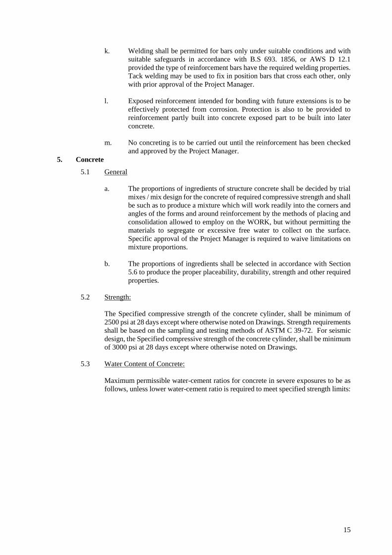
15
k. Welding shall be permitted for bars only under suitable conditions and with
suitable safeguards in accordance with B.S 693. 1856, or AWS D 12.1
provided the type of reinforcement bars have the required welding properties.
Tack welding may be used to fix in position bars that cross each other, only
with prior approval of the Project Manager.
l. Exposed reinforcement intended for bonding with future extensions is to be
effectively protected from corrosion. Protection is also to be provided to
reinforcement partly built into concrete exposed part to be built into later
concrete.
m. No concreting is to be carried out until the reinforcement has been checked
and approved by the Project Manager.
5. Concrete
5.1 General
a. The proportions of ingredients of structure concrete shall be decided by trial
mixes / mix design for the concrete of required compressive strength and shall
be such as to produce a mixture which will work readily into the corners and
angles of the forms and around reinforcement by the methods of placing and
consolidation allowed to employ on the WORK, but without permitting the
materials to segregate or excessive free water to collect on the surface.
Specific approval of the Project Manager is required to waive limitations on
mixture proportions.
b. The proportions of ingredients shall be selected in accordance with Section
5.6 to produce the proper placeability, durability, strength and other required
properties.
5.2 Strength:
The Specified compressive strength of the concrete cylinder, shall be minimum of
2500 psi at 28 days except where otherwise noted on Drawings. Strength requirements
shall be based on the sampling and testing methods of ASTM C 39-72. For seismic
design, the Specified compressive strength of the concrete cylinder, shall be minimum
of 3000 psi at 28 days except where otherwise noted on Drawings.
5.3 Water Content of Concrete:
Maximum permissible water-cement ratios for concrete in severe exposures to be as
follows, unless lower water-cement ratio is required to meet specified strength limits:

16
__________________________________________________________________________
Type of Structure Structure Structure
Continuously wet or exposed to sea
Frequently freezing or sulfates
and thawing
i. Thin sections & sections with
less than 1” cover over
steel.
0.45
0.402
ii. All other
Structures
0.50
0.452
NOTE:
1. Concrete should also be air-entrained.
2. If S.R. Cement is used permissible water-cement ratio may be increased by 0.05.
5.4 Slump:
Unless otherwise permitted or specified, the concrete shall be allowed to have a slump
of 1-1/2" (37.50 mm) or less provided the requisite cube strength is obtained, A
tolerance of upto 1/2" (12.50 mm) above the indicated maximum shall be allowed for
individual batches provided the average for all batches or the most recent 10 batches
tested, whichever is fewer, does not exceed the maximum limit. Concrete of lower
than usual slump may be used provided it is properly placed and consolidated. The
slump shall be determined by the “Test for Slump for Portland Cement Concrete"
(ASTM C-143).
5.5 Admixtures
If required or permitted, admixtures used shall be in accordance with the
manufacturer's instructions except as otherwise specified herein.
Chemical admixtures may be used as per the recommendation of the suppliers to
achieve the desired strength and workability.
Mineral admixtures such as Silica fume and fly ash and Ground Granulated Blast
furnace Slag (GGBS) as partial replacement of cement may be used. These concrete
mixes have to be designed to achieve the desired strength at the target ages.

17
5.6 Methods of Obtaining Mix Design;
For concrete of normal weight, mix proportions to provide the desired characteristics
shall be developed by using the methods/procedure covered by the latest edition of
Recommended Practice for Selecting Proportions for Normal Weight Concrete ACI
211.1.
Trial mixtures having proportions and consistencies suitable for the WORK shall be
made based on ACI 211.1, using at least three different water-cement ratios which
will produce a range of strengths encompassing those required for the WORK. Trial
mixes shall be designed to produce the specified slump. The temperature of concrete
used in trial batches shall be reported.
For each water-cement ratio, compression test of cylinder/cube shall be made, cured,
and tested in accordance with "ASTM C - 39 or BS 1881". From the results of these
tests a curve shall be plotted showing the relationship between the water-cement ratio
and compressive strength. From this curve, the water-cement ratio to be used in the
concrete shall be selected to produce the required/specified design strength. The
cement content and mix proportions to be used shall be such that this water-cement
ratio is not exceeded when slump is the maximum permitted. Control in the field shall
be based upon maintenance of proper cement content and slump.
5.7 Batching:
a. All cement, including cement supplied in bulk, shall be batched by weight. A
bag of cement, unless marked otherwise, may be taken as 112 Ibs (50 kg) or
as directed by the Project Manager.
b. Aggregate shall be batched by weight, duly allowance being made for water
content. Aggregate may be batched by volume only with the prior permission
of Project Manager. The apparatus for weight batching may be an integral
part of the mixer or a separate unit of a type approved by Project Manager. It
shall be accurate within 2% and shall be checked for accuracy at least once a
week.
c. Where the batching plant is of the type in which cement and aggregate are
weighed in the same compartment, the cement shall be introduced into the
compartment between two sizes of aggregate.
d. Where volumetric batching of aggregate is permitted, gauge boxes shall be
provided for measuring the coarse and-the fine aggregate. These shall be deep
and narrow rather than shallow and wide. Tests for the bulking of sand shall
be made at intervals and the necessary quantity of sand added.
e. Each batch shall be so charged into the mixer that some water will enter in
advance of the cement and aggregates. Water shall continue to flow for a
period which may extend to the end of the first 25 percent of the specified
mixing time.
5.8 Mixing
a. The concrete shall be mixed in an approved batch mixer conforming to the
requirement of B.S 1305. It shall be fitted with the manufacturer's plate
stating the rated capacity and the recommended number of revolutions per
minute and shall be operated in accordance therewith. It shall he equipped
with a suitable charging mechanism and an accurate water measuring device.

18
b. Mixing shall continue for the period recommended by the mixer manufacturer
or until apparently the mix is uniform in color, whichever period is longer. If
it is desired to use a mixing period less than 1-1/2 minute Project Manager
Approval shall be obtained in writing.
c. Controls shall be provided to ensure that the batch cannot be discharged until
the required mixing time has elapsed. At least three quarters of the required
mixing time shall take place after the last of the mixing water has been added.
d. The interior of the mixer shall be free of accumulations that will interfere with
mixing action. Mixing blades, shall be replaced when they have lost 10% of
their original height.
e. Concrete shall be mixed only in quantities for immediate use. Concrete which
has set shall not be re-tempered, but shall be discarded.
5.9 Transportation:
a. The concrete shall be transported from the place of mixing to the place of
final deposit as rapidly as practicable by means which will prevent
segregation or loss or addition to ingredients. It shall be deposit as nearly as
practicable in its final position so as to avoid re-handling or flowing. All skips
vehicles, or containers used for transporting the concrete shall be thoroughly
cleaned.
b. During hot or cold weather, concrete shall be transported in deep containers
to minimize the loss of water/heat.
5.10 Placing
a. Before placing of concrete, form works shall have been completed, water
shall have been removed, reinforcement shall have been secured in place,
expansion joint material, anchors, and other embedded items shall have been
kept in position, and the entire preparation shall have been approved.
b. No concrete is to be placed into the foundation trenches until the ground to
receive the same has been examined and approved by Project Manager for
this purpose.
c. The actual sequence of construction proposed by CONTRACTOR shall be
subject to Project Manager’s approval before construction starts on any part
of the structure, and this sequence shall not be varied without Project
Manager’s prior approval.
d. The concrete shall be placed after it has been mixed as soon as practicable.
Once the concrete has left the mixer no more water shall be added, although
the concrete may be mixed or agitated to help maintain workability. The
concrete shall not be used if, through any cause, the workability of the mix at
the time of placing is too low for it to be compacted fully and to an acceptable
finish by whatever means are available.
The time between mixing and placing should be reduced if the mix is richer
or the initial workability of the mix is lower than normal, if a rapid hardening
cement or an accelerator is used, or if the work is carried out at a high
temperature or exposed to a drying atmosphere. CONTRACTOR shall ensure

19
that the delay between mixing and placing does not exceed 30 minutes under
any circumstances. Any concrete which does not satisfy this requirement shall
not be used.
e. The concrete shall be deposit as nearly as possible in its final position to avoid
re-handling. In no circumstances may concrete be made to flow along the
forms by the use of vibrators, Concreting shall be carried out on as a
continuous operation using methods which shall prevent separation loss of
ingredients.
f. The free fall of concrete shall not be allowed to exceed eight feet and where
it is necessary for the concrete to be lowered more than this amount, it is not
to be dropped into its final position, but it is to be placed through pipe, the
lower end of which shall be kept in, or close to the freshly deposit concrete.
The dia of the pipe shall not be than 4 times the maximum size of aggregate.
g. For mass concrete, concrete shall be placed in layers approximately 18” (450
mm) thick. Vibrator heads shall extend into the previously placed layer.
h. The workmen carrying concrete to the SITE, and all other workmen moving
about before the concrete is placed shall move only along runways or planks
placed over the forms.
i. Prior to the laying of concrete on load bearing masonry walls, bearing plates
and at other points, as may be directed by Project Manager, the surface will
be brought to a true, hard smooth, level using a cement sand mortar in the
ratio of 1 volume of cement to 3 volumes of sand. Two layers of building
paper weighing 1.3 oz/sq. ft (400 g/m) will then be laid flat to separate the
concrete from the surface on which it is to be laid.
5.11 Construction Joints:
a. Concreting shall be carried out continuously upto construction Joints, the
position and arrangement of which shall be pre-determined with the approval
of the Project Manager.
b. Joints not shown on the Drawings shall be so made and located as to least
impair the strength of the structure and shall need prior approval of Project
Manager. In general, they shall be located near the middle of the spans of
slabs and beams unless a secondary beam intersects a main beam at this point,
in which case the joint in the main beam shall be offset to a distance equal to
twice the width of the secondary beam. Joints in walls and columns shall be
at the underside of floors slab or beams, and at the top of footings. Beams,
brackets, columns, capitals, haunches, and drop panels shall be placed at the
same time as slabs. Joints shall be perpendicular to the main reinforcement.
c. All reinforcing steel shall be continued across joints. Key and inclined dowels
shall be provided as directed by Project Manager. Longitudinal keys at least
1- 1/2 ( 40 mm. ) deep shall be provided in all joints in walls and between
walls and slab or footings.
d. When the work is to be resumed on a surface which has hardened, such
surface shall be roughened in an approved manner which will expose the
aggregate Uniformly and will not leave laitance, loosened particles of
aggregate or damaged concrete at the surface.

20
e. The hardened concrete of construction joints and of joints between footings
and walls or columns, between walls or columns and beams or floors they
support, joints in un-exposed walls and all others not mentioned below shall
be dampened (but not saturated) immediately prior to placing of fresh
concrete.
f. The hardened concrete of joints in exposed work, joints in the middle of
beams, and slabs and joints in work designed to contain liquids shall be
dampened (but not saturated) and then thoroughly covered with a coat of
cement grout of similar proportions to the mortar in the concrete The grout
shall be as thick as possible on vertical surface and at least 1/2" (12.0 mm)
thick on horizontal surface. The fresh concrete shall be placed before the
grout has attained its initial set.
g. Where the concrete has not fully hardened, all laitance shall be removed by
scrubbing the wet surface with wire or bristle brush. Care being taken to avoid
dislodging of particles of aggregate. The surface shall then be coated with
neat cement grout. The first layer of concrete to be placed on this surface shall
not exceed 6" (150 mm) in thickness, and shall be well rammed against old
work, particular attention being paid to corners and close spots.
h. Stop ends for movement joints or construction joints shall be made by
splitting them, along the lines of reinforcement or the concrete. Stop ends
made of expanded metal or similar material may only be left permanently in
the concrete with prior written approval of Project Manager. Where such stop
ends are used , no metal may be left permanently in the concrete closer to the
surface of the concrete than the specified cover to the reinforcement. Wood
strips inserted for architectural treatment shall be kerfed to permit swelling
without pressure on the concrete.
5.12 Embedded Items:
a. The material, design and location of water stops in joints shall be as indicated
in the Drawings. Each piece of pre-molded water stop shall be of maximum
practicable length in order that the number of end joints will be held to a
minimum.
Joints at intersections and at end of pieces shall be made in the manner most
appropriates to the material being used. Joints shall develop effective water
tightness fully equal to that of the continuous water-stop material, and shall
permanently develop not less than 50% of the mechanical strength of the
parent section, and shall permanently retain their flexibility.
b. Electric conduits and other pipes which are planned to be embedded shall not,
with their fittings, displace more than four percent of the area of the cross
section of a column on which stress is calculated or which is required for fire
protection. Sleeves, conduits, or other pipes passing through floors, walls, or
beams shall be of such size or in such location so as not to impair unduly the
strength of the construction. Such sleeves, conduits in compression in the
displaced concrete, provided that they are not exposed to rusting or other
deterioration, are of un-coated or galvanized iron or steel not thinner than
standard steel pipe, having a nominal inside diameter not over 2" (50 mm)
and are spaced at centers not less than thrice their diameter. Except when
plans of conduits and pipes are approved by Project Manager embedded pipes
or conduits other than those merely passing through, shall not be larger in
outside diameter than one-third or the thickness of the slab, walls, or beam in

21
which they are embedded nor shall be spaced closer than three diameters on
center, nor so located as to impair unduly the strength of the construction.
Sleeve pipes, or conduits within the limitations of this section may be
embedded in concrete with the approval of Project Manager, provided they
are not considered to replace the displaced concrete.
c. All sleeves, inserts, anchors, and embedded items required for adjoining work
or for its support shall be placed prior to concreting.
All-Contractors whose work is related to the concrete or must be supported
by it shall be given ample notice and opportunity to introduce and/or furnish
embedded items before the concrete is placed.
d. Expansion joint material, water stop and other embedded items shall be
positioned accurately and supported against displacement. Voids in sleeves,
inserts, and anchor slots shall be filled temporarily with readily removable
material to prevent the entry of concrete into the voids.
5.13 Consolidation:
a. All concrete shall be consolidated by vibration, so that the concrete is
thoroughly worked around the reinforcement, around embedded items, and
into comers of form, eliminating all air or stone pockets which may cause
honeycombing, pitting, or planes of weakness. Internal vibrators shall have a
minimum frequency of 800 vibrations per minute and sufficient amplitude to
consolidate the concrete effectively.
Vibrators shall be inserted and withdrawn at points approximately 18" apart
(450 mm). At each insertions, the duration shall be sufficient to cause
consolidation, generally from 5 to 15 sec. A spare vibrator shall be kept on
the SITE during all concreting operations. Where the concrete is to have an
as-cast finish, a full surface of mortar shall be brought against the form by the
vibration process supplemented if necessary by spading to work the coarse
aggregate back from the formed surface.
b. If there is any tendency for the mix to segregate during consolidation,
particularly if this produces excessive laitance, the mix proportions shall be
modified to affect an improvement in the quality of the concrete to the
satisfaction of Project Manager and in conformity with the provisions of
Clause 5.
c. Vibrators shall not be allowed to contact the form work for exposed concrete
surface.
d. Mechanical vibrators shall be of a type suited in the opinion of Project
Manager to the particular conditions.
e. Over-vibration or vibration of very wet mix is harmful and should be avoided.
5.14 Curing and Protection:
a. Beginning immediately after placement, concrete shall be protected from
premature drying, excessively hot or cold temperatures, and mechanical
injury, and shall be maintained with minimal moisture loss at a relative
constant temperature for the period necessary for hydration of the cement and

22
hardening of the concrete. The materials and methods of curing shall be
subject to approval of Project Manager.
b. For concrete surfaces not in contact with forms, one of the following
procedure shall be applied immediately after completion and finishing:
Ponding or continuous sprinkling.
Application of absorptive mats or fabric kept continuously wet.
Application of water proof sheet materials approved by Project Manager.
Application of other moisture retaining covering as per approved.
Application of curing compound conforming to AS'I'M C 309. The
compound shall be applied in accordance with the recommendations of
the manufacturer immediately after any sheen which develops after
finishing has disappeared from the concrete surface. It shall not be used
on any surface against which additional concrete or other materials to be
bonded unless it is proved that the curing compound will not prevent
bond, or unless positive measures are taken to remove it completely from
area to receive bonded applications.
c. Moisture loss from surface placed against wooden forms or metal forms
exposed to heating by the sun shall be minimized by keeping forms wet until
they can be safely removed. After form removal, the concrete shall he cured
until the end of the limit prescribed in Clause 6.10.d by one of the methods
of Clause 6.10.b.
d. Curing in accordance with clause 6.10.a & 6.10.b shall be continued for at
least 14 days in the case of all concrete except concrete with Rapid hardening
Portland cement for which the period shall be at least 7 days.
Alternatively if tests are made of cylinders/cubes kept adjacent to the
structure and cured by the same methods, moisture retention measures unless
stated otherwise on drawings, may be terminated when the average
compressive strength has reached 70 percent of the minimum specified
Works strength. If one of the first four curing procedures of clause 6.10.b is
used initially, it may be replaced by one of the other procedures of that Clause
any time provided the concrete is not permitted to become surface dry during
the transition.
e. When the mean daily outdoor temperature is less than 41 degree F (5 C) then
temperature of the concrete shall be maintained between 50-68F (10C-20C)
for the required curing period of Clause 6.10.d. When necessary arrangements
for heating, covering, insulation or housing the concrete work shall be made
in advance of placement and shall be adequate to maintain the required
temperature without injury to concentration of heat. Combustion heaters shall
not be used during the first 24 hours unless approved precautions are taken to
prevent exposure of the concrete to exhaust gases which contain carbon
dioxide.
f. When necessary, provision for windbreak, shading for spraying, sprinkling,
ponding or wet covering with a light colored material shall be made in
advance of placement, and such protective measures shall be taken as quickly
as concrete hardening and finishing operations will allow.
g. Changes in temperature of the air immediately adjacent to the concrete during
and immediately following the curing period shall be kept as uniform as

23
possible and shall not exceed 5F (3C) in any one hour or 50F (28C) in any 24
hour period.
h. During the curing period, the concrete shall be protected from damaging
mechanical disturbances, such as load stresses, heavy shock and excessive
vibration. All finished concrete surfaces shall be protected from damage by
construction equipment, materials or methods by application of curing
procedures, and by rain or running water, self-supporting structures shall not
be loaded in such a way as to over stress the concrete.
5.15 Works In Extreme Weather:
a. Unless adequate protection is provided and approval is obtained concrete
shall not be placed during rain. Rain water shall not be allowed to increase
the mixing water nor to damage the surface finish.
b. When the temperature of the surrounding air is expected to be below 40
degrees F (4.4 C) during placing or within 24 hours thereafter, the temperature
of the plastic concrete, as placed shall not be lower than 55 degrees F (13 -
C) for sections less than 12" (300 mm) in any dimension nor 50F (1 OC) for
any other sections.
When necessary, concrete materials should be heated before mixing and
carefully protected after placing; in general, heating of mixing water alone to
about 140F (60C) may be sufficient for this purpose. Dependence should not
be placed on salt or other chemicals for the prevention of freezing. No frozen
material or materials, containing ice shall be used. All concrete damaged by
frost shall be removed. It is recommended that concrete exposed to the action
of freezing weather should have entrained air and the water content of the mix
should not exceed 5.5 gallons (25 liters) per bag of cement. If water or
aggregate is heated above I OOF (38C) the water shall be combined with the
aggregate in the mixer before cement is added. Cement shall not be mixed
with water or with mixtures of wafer and "aggregate having a temperature
greater than 100F(38C).
c. During hot weather, (lie temperature of the concrete as placed shall not be so
high as to cause difficulty from loss of slump, flash set, or cold joints and
should not exceed 90F (32.C). For massive concrete this temperature should
not exceed 70F (21 .C). When the temperature of the concrete exceeds 90F
(32C), precautionary measures approved by Project Manager shall be put into
effect. When the temperature of the steel is greater than 122F (50C) steel
forms and reinforcement shall be sprayed with water just prior to placing the
concrete. The ingredients shall be cooled before mixing, or flake ice or well-
crushed ice of a size that will melt completely during mixing may be
substituted for all or part of the mixing water if, due to high temperature, low
slump, flash set or cold joints are encountered.
Other precautions recommended by ACI standard 305R-91 shall also be
adopted.
6. Tests for Concrete Quality
6.1 General
CONTRACTOR shall make standard cylinder / cube (sample) by standard method of
concrete for testing at Project Manager’s direction. Proper facilities shall be provided
for making and curing the test specimens in accordance with the specifications A

24
competent person shall be employed by the CONTRACTOR whose first duty shall be
to supervise all stages in the preparation and placing of the concrete. All test
specimens shall be made and SITE tests carried out under his direct supervision and
at CONTRACTOR'S cost.
Permanent record of concrete poured, samples made, and compressive strength results
obtained shall be carefully maintained at the site.
6.2 Samples
Conduct compressive strength tests on at least, one test cylinder / cube sample per 50
cubic yards of concrete (38 cu meters) with a minimum of one sample per concrete
pour. Each test sample shall consist of no less than three concrete test cylinders/cubes
made from a single sample of concrete from a randomly selected batch of concrete,
taken at point of discharge from mixer or truck, cured under standard conditions. One
cylinder/cube from each sample shall be tested at age 3 days and two at age 28 days
unless otherwise directed by the Project Manager.
6.3 Adequacy of Mix
In case of Concrete mix, the appropriate strength requirement shall be considered to
be satisfied if none of the strengths of the specimen is below the specified strength or
if the average strength of the three specimens is not less than the specified strength
and the difference between the greatest and least strengths is not more than 20% of
that average.
When the results of tests show that the strength of any concrete is below the minimum
specified, Project Manager may give instructions for the whole or part of the work
concerned to be removed and be replaced at the expense of CONTRACTOR.
CONTRACTOR shall bear the cost of any other part of his, or any other
CONTRACTORS work, which has to be removed and replaced as a result of the
defective concrete. If any concrete is held to have failed. Project Manager may order
the proportions of that class of concrete to be changed in order to provide specified
strength.
7. Finishing of Formed Concrete
7.1 General
a. After removal of forms the surfaces of concrete shall be given one or more of
the finishes specified below in locations designated by the Drawing or as
specified in Clause 8.5.
b. When finishing is required to match a small sample furnished to
CONTRACTOR, the sample finish shall be reproduced on nil area at least
100 square feet in an inconspicuous location designated by Project Manager
before proceeding with the finish in the specified location.
7.2 As-Cast Fishes
a. Rough Form Finish:
No selected form facing materials shall be specified for rough form finish
surfaces. Tie holes and defects shall be patched. Unless if required to be
retained if so directed by Project Manager. Fins exceeding 1/4" (6 mm) in
height shall be chipped off or rubbed off. Otherwise, surfaces shall be left
with the texture imparted by the forms.

25
b. Smooth Form Finish:
The form facing material shall produce a smooth hard uniform texture on the
concrete.
It may be plywood, tempered concrete-form grade hardboard, metal, plastic
paper, or other approved material capable of producing the desired finish. The
arrangement of the facing material shall be orderly and symmetrical, with the
number of seams kept to the practical minimum. It shall be supported by studs
or other backing capable of preventing excessive deflection. Material with
raised grain, torn surfaces, worn edge, patches, dents, or other defects which
will impair the texture of the concrete surface shall not be used. Tie holes and
defects shall be patched. All fins shall be completely removed.
7.3 Architectural Finishes
a. Textured Finishes
Textured form liners may be of formed plastic sheet, wood, sheet metal, or
other material designated in Drawings. Liner panels shall be secured in forms
by cementing or stapling, but not by methods which will permit impressions
of nail heads, screw heads washers, or the like to he imparted to the surface
of the concrete, unless shown otherwise on the Drawings. Edges of textured
panels shall be sealed to each other or to dividing strips, if specified or shown,
to prevent bleeding of grout. The sealant used shall be non-staining to the
surface.
b. Applied Finishes
When finishes of plaster or similar trowelled materials are to be applied, the
surface of the concrete shall be prepared to ensure permanent adhesion of the
finish. If the concrete is less than 24 hours old, it can be roughened with a
heavy wire brush or scouring tool. If the concrete is older the surface may be
roughened mechanically or by etching with dilute hydrochloric acid. After
roughening, the surface shall be washed free of all dust, acid, chemical
retarder, and other foreign material before the final finish is applied.
7.4 Rubbed Finishes
The following finishes .shall be produced on concrete with a smooth form finish.
Where smooth rubbed finish is to be applied, the forms shall have been removed and
necessary patching completed as soon after the cement of the concrete as possible
without compromising any structural requirements.
a. Smooth Rubbed Finish
Smooth rubbed finish shall be produced on newly hardened concrete not later
than a day following form removal.
Surfaces shall be wetted and rubbed with carborundum brick or other abrasive
until uniform color and texture are produced. No cement grout shall be used
other than the cement paste drawn from the concrete itself by the rubbing
process.

26
b. Grout Cleaned Finish
No cleaning operations shall be undertaken until all contiguous surfaces to be
cleaned are completed and accessible. Cleaning as the work progresses shall
not be permitted.
Mix 1 part Portland cement and 1-1/2 part fine sand with sufficient water to
produce a grout having the consistency of thick paint. While Portland cement
shall be substituted for a part of the grey Portland cement in order to produce
a color matching the color of the surrounding concrete, as determined by a
trial patch. Wet the surface of the concrete sufficiently to prevent absorption
of water from the grout and apply the grout uniformly with a brush or a spray
gun. Immediately after applying the grout, scrub surface vigorously with a
cork float or stone and fill all air bubbles and holes. While the grout is still
plastic, remove all excess grout by working the surface with a rubber float,
sack or other means. After the surface whitens from drying (about thirty
minutes at normal temperature) rub vigorously with clean burlap. The finish
shall be kept damp for at least 36 hours after final rubbing.
c. Cork Floated Finish
1. Remove forms at an early stage, within 2 to 3 days of placement
where possible.
2. Remove ties, and all burrs and fins.
3. Mix 1 part Portland cement and 1 part fine sand with sufficient water
to produce a stiff mortar.
4. Dampen surface.
5. Apply mortar with firm rubber float or with trowel, filling all surface
voids.
6. Apply a small amount of water with a fog spray to prevent too rapid
drying of compressed mortar.
7. Apply a small amount of water with a fog sprayer.
8. Produce the final texture with a cork float using a swirling motion.
7.5 Unspecified Finishes
If the finish is not specified in the Drawings, the following finishes shall be used as
applicable:
a. Rough Form Finish
For all concrete surface not exposed to public view and / or are specified to
have subsequent finishing.
b. Smooth Form Finish
For all concrete surfaces exposed to public view and or are not required to
have subsequent finishing.
7.6 Related Unformed Surfaces
Tops of walls or buttresses, horizontal offsets, and similar unformed surfaces
occurring adjacent to formed surfaces shall be struck smooth after concrete is placed
and shall be floated to a texture reasonably consistent with that of the formed surfaces.
Final treatment on form surfaces shall continue uniformly across the unformed
surfaces.

27
8. Repair of Surface Defects
8.1 General
a. Any concrete failing to meet the specified strength or not formed as shown
on Drawings, concrete with surface beyond tolerances or with defective
surfaces which cannot be properly repaired or patched in the opinion of
Project Manager shall be removed and replaced at CONTRACTOR’s
expenses. Project Manager may reject any defective concrete and order it to
be cut out in part or in whole and replaced at the CONTRACTOR’s expense.
Only in case of minor surface defects Project Manager may approve a surface
treatment in accordance with the Clause. 9.2
b. All ties and bolt holes and all repairable defective areas shall be patched
immediately after the removal of forms.
8.2 Repair of Defective Areas
a. All honeycombed and other defective concrete shall be removed down to
sound concrete. The area to be patched and area at least 6" (150 mm) wide
surrounding it shall be dampened to prevent absorption of water from the
patching mortar. A bonding grout shall be prepared using a mix of
approximately 1 part cement to 1 part fine sand or an approved bonding agent
shall then be well brushed/ applied into the surface.
b. The patching mixture shall be made of the same material and of
approximately the same proportions as used for the concrete, except that the
coarse aggregate shall be omitted and the mortar shall consist of not more
than 1 part cement to 2-1/2 parts sand by damp loose volume. White Portland
cement shall be substituted for a part of the grey Portland cement on exposed
concrete in order to produce a color matching the color of the surrounding
concrete, as determined by a trial patch.
c. The quantity of mixing water shall not be more than necessary for handling
and placing. The patching mortar shall be mixed in advance and allowed to
stand with frequent manipulation with a trowel, without addition of water,
until it has reached the stiffest consistency that will permit placing.
d. After surface water has evaporated from the area to be patched, the bond coat
shall be well brushed into the surface. When the bond coat begins to lose the
water sheen, the premixed patching mortar shall be applied. The mortar shall
be thoroughly consolidated into place and struck off so as to leave the parch
slightly higher than the surrounding surface to permit initial shrinkage; it shall
be left undisturbed for at least one hour before being finally finished. The
patched area shall be covered by approved curing compound, except as
specified in Clause 9.2 g. Metal tools shall not be used in finishing a patch in
a formed wall which will be exposed.
e. Whereas-cast finishes are specified, the quantity of patched area shall be
strictly limited. The combined total of patched areas in as-cast concrete
surfaces shall not exceed 2 square ft. in each 1000 square feet (2 sq. m in each
1000 sq.m) of as-cast surface. This is in addition to form tie patches, if the
project design permits to fall within as-cast areas.
f. Any patches in as-cast architectural concrete shall be indistinguishable from
surrounding surfaces. The mix formula for patching mortar shall be
determined by trial to obtain a good color match with the concrete when both

28
patch and concrete are cured and dry. After initial set, surface of patches shall
be dressed manually to obtain the same texture as surrounding surfaces.
g. Patches in architectural concrete surfaces shall be cured continually for 7
days. Patches shall be protected from premature drying to the same extent as
the body of the concrete.
8.3 Tie and Bolt Holes;
After being cleaned and thoroughly dampened, the tie and bolt holes shall be filled
solid with patching mortar.
8.4 Proprietary Materials:
If permitted or required by Project Manager proprietary compounds for adhesion or
as patching ingredients may be used in lieu of or in addition to the foregoing patching
procedures. Such compounds shall be used in accordance with the manufacturer's
recommendation with prior approval of Project Manager.
9. Concrete Construction Tolerance
Where tolerances are not stated in the Specifications or Driving for any individual structure
or feature, maximum permissible deviations from established lines, grades and dimensions
shall conform to the following. The CONTRACTOR is expected to set and maintain concrete
forms so as to ensure completed work within the tolerance limits. These allowable tolerances
shall not relieve CONTRACTOR of his responsibility for correct fitting of indicated materials.
These tolerances are not cumulative.
9.1 Variation from the plumb (or as specified for sloped walls)
a. In the lines and surfaces of columns, piers and walls.
Maximum for the entire length or height: 3/16" (4.5 mm)
b. For exposed corner columns, control joint grooves and other conspicuous
lines.
Maximum for the entire length or height: 3/16"(4.5 mm)
9.2 Variation from the levels or the grades indicated on Drawings
a. In floors, ceilings, beam soffits and in arises.
Maximum for the entire length: l/4"(omm)
b. For exposed lintels, sills, parapets, horizontal grooves of 50 feet or more in
length , and other conspicuous lines:
Maximum for the entire length: 1/4"(6 mm)
9.3 Maximum allowable constant Variation of the entire building lines from established
position of property tines and related position of columns, walls and partitions.
Maximum for the entire length: 1" (25 mm)
9.4 Variation of the size and locations of sleeves, floors openings
and wall openings: 1/4" (6m)
9.5 Variation In cross-sectional dimensions of columns and beams.

29
Minus: 1/4" (6 mm)
Plus: 1/2" (12.0 mm)
9.5a. In thickness of Slabs & Walls. 1/4" (6mm).
9.6 Footings
a. Variations in dimensions in plan.
Minus: 1/2" (12.0 mm)
Plus (plus variation applied to concrete only,
to bars dowels) 2” (50 mm)
b. Misplacement or eccentricity of concrete.
2 percent of the footing width in the direction
of misplacement but not more than 2” (50 mm)
c. Reduction in thickness
Minus 5 percent of specified thickness.
9.7 Variation in Steps
a. Rise: 1/8" (3 mm)
Tread: 1/4" (Omm)
b. In consecutive steps
Rise: 1/16" (1.0 mm)
Tread: 1/8" (3 mm)
9.8 Tolerance for Pre-cast Concrete:
Forms must be true to size and dimensions of concrete members shown on the plans
and be so constructed that the dimensions of the finished product will be within the
following limits at the time of placement of these units in the structure, unless
otherwise noted on Project Manager's Drawings.
a. Overall dimensions of members per 10 ft (3 mm):
+/- 1/16" (1.0mm)
b. Cross-sectional dimensions' Section less than 3"(75
mm): +/- 1/8" (3 mm)
Section over 3" (75 mm) less than 18" (450
mm): +/- 1/8" (3 mm)
Section over 18" (450 mm): +/- 1/4" (6 mm)
c. Deviations from straight lines in long sections. Not
more than 1/8 inch per 10 ft. (3 mm / 3 m)
d. Deviation from specified camber +/- 1/16" (1.5 mm)
per 10 fl (3m) of span. Maximum differential
between adjacent units in erected position.¼ inch (6
mm)
9.9 Tolerance for Pavements

30
a. Ramps.
Departure from established alignment +/- 1/4"
inch (6 mm)
Departure from established longitudinal on any
line. +/- 1/4" (6 mm) grade
Departure from transverse template colour
except al transverse joints+/- 1/8 inch (+/- 3
mm)
Departure from transverse template control at
transverse joints 1/4"(+/-6 mm) in width of one
traffic lane,
9.10 Pavements for Parking Areas
Twice values listed for ramp pavements.
10. Plant and Equipment
10.1 Formwork
a. Forms shall be used, wherever necessary, to confine the concrete and shape it to the
required dimensions. Forms shall have sufficient strength to with stand the pressure
resulting from placement and vibration of the concrete and shall have sufficient
rigidity to maintain specified tolerances.
Structurally adequate, form work shall also conform to the requirements of the special
architectural finishes of the in-situ Plain and Reinforced Concrete specified/or shown
on the Drawings. Shop drawings of such form shall be subject to the approval of the
Project Manager prior to its use. Project Manager shall refuse concreting of any part
which in his opinion may not yield specified finishes.
b. Earth cuts shall not be used as forms for vertical surface or reinforced concrete work
unless required or permitted.
c. Mud centering shall not be permitted without the prior approval of the Project
Manager.
d. Form work shall be made of either timber, steel, plywood, proprietary building boards
and such special material, as may be shown on the drawings or approved by the
Project Manager which gives the required finish to the surface of concrete. Wooden
frame Work shall be free from loose knots and shall be well seasoned. For the external
concrete finishes 1/16" (1.5 mm) thick mild steel sheet forms shall he used.
CONTRACTOR shall furnish shop drawings of such form work prepared on the basis
of architectural concept for the approval of the Project Manager.
e. Form work shall conform to the shape, lines and dimensions as shown on the plans,
and be so constructed as to remain sufficiently rigid dining the placing and
compacting of concrete, and shall he sufficiently tight of prevent loss of cement slurry.
The design and engineering of the form work, as well as its construction, shall be the
responsibility of CONTRACTOR. Where necessary to maintain the specified
tolerances, the form work shall be cambered to compensate for anticipated deflections
in the form work due to the weight and pressure of the fresh concrete and due to
construction loads.

31
CONTRACTOR shall establish and maintain in an undisturbed conditions and until
final completion and acceptance of the WORK, sufficient control points and bench
marks to be used for reference purpose to check tolerances.
f. Requirements for facing materials are given in clause 8 "Finishing of formed
Concrete". The maximum deflection of facing materials reflected in concrete surfaces
exposed to view shall be 1/240 of the span between structural members.
g. Where natural plywood form finish, grout cleaned finish, smooth rubbed finish,
scrubbed finish, or sand floated finish is required, forms shall be smooth (faced with
plywood, liner sheets, or prefabricated panels) and true to line, in order that the
surfaces produced with required little dressing to arrive at true surfaces. Where any
as-cast finish is required, no dressing shall be permitted in the finishing operation.
h. Whereas-cast surfaces, including natural plywood form finish, are specified, the
panels of materials against which concrete is cast shall be arranged orderly with joints
between panels planned in approved relations to opening, building corners, and other
architectural features.
i. Where panels for as-cast surfaces are separated by recessed or otherwise emphasized
joints, the structural design of the forms shall provide for locating form ties within
the, joints so that patches of the holes will not fall within the panel areas.
j. Forms shall not be re-used if there is any evidence of surface wear and tear or defect
which would impair the quality of the surface. Forms shall he thoroughly cleaned and
properly coated before re-use.
k. The formwork may be designed so that soffits of slabs and sides of beams, columns,
and wall may be removed first leaving the forms to the soffits of beams and their
supports in position.
l. Positive means, wedges or jacks of accurate adjustment and proper removal of shores
and struts shall be provided and all settlement shall be taken up during placing of
concrete. Forms shall also be securely braced against lateral deflections.
m. Where concreting of narrow members' is required to be carried out within form work
of considerable depth, temporary openings in the sides of the form work shall be
provided where necessary to facilitate the placing and consolidation of the concrete.
Small temporary openings shall be provided at the bottom of the form work to
columns, walls and deep beams to permit the cleaning out of debris and observations
immediately before concrete is deposit.
n. Form ties shall be constructed so that the ends or end fasteners can be removed
without causing appreciable spalling at the faces of the concrete. After the ends or end
fasteners of form ties have been removed, the embedded portion of the ties shall
terminate not less than twice the diameter or twice the minimum dimension of the tie
from the formed faces of concrete to be .permanently exposed to view except that in
no case shall this distance be less than 3/4" (19 mm) when the formed Face of the
concrete is not to be permanently exposed to view, form tie may be cut off flush with
the formed surfaces. Through bolts shall be permitted provided that they are greased
to allow for easy withdrawal and the holes subsequently made good. Through bolts
are not to be used on water-retaining structures.
o. At construction joints, contact surface of the form sheathing for flush surfaces
exposed to view shall overlap the hardened concrete in the previous placement by not

32
more than 1" (25 mm). The forms shall be held against the hardened concrete to
prevent offsets or loss of mortar at the construction joint and to maintain a true surface.
p. Runways or planks for moving labor and equipment shall be provided with struts or
legs and shall be supported directly on the formwork or structural member without
resting on the reinforcing steel.
q. All surfaces of the embedded items shall be cleaned and any accumulated mortar or
grout from previous concreting and of all other foreign material is removed before
concrete is placed in them.
r. Board forms having joints opened by shrinkage of the wood shall be swelled until
closed by wetting before concrete is placed. Plywood and other wood surface not
subject to shrinkage shall be sealed against absorption of moisture from the concrete
either by (1) a field applied, approved form oil or sealer, or (2) a factory applied non-
absorptive liner. When forms are coated to prevent bond with concrete, it shall be
done prior to placing of the reinforcing steel. Care shall be taken that such approved
coating is kept out of contact with the reinforcement. Whereas-cast finishes are
required, materials, which will impart a stain to the concrete shall not be applied to
the form surfaces. Where the finished surface is required to be painted, the material
applied to form surface shall be compatible with the type of paint to be used.
s. In normal circumstances generally where temperatures are above 68F (20C) where
ordinary cement is used, forms may be struck after expiry of the following periods.
Walls, columns and vertical sides of beams 48 hours
Slabs 14 days
Beams soffits 14 days
Removal of shores or props to slabs:
1. Spanning over 14 ft (4 meters) 21 days
Removal of shores or props of beams:
1. Spanning upto 20 ft. (6 meters) 18 days
2. Spanning over 20 ft. (6 meters) 25 days
For rapid hardening cement 1/2 of the above period will be sufficient in all cases
except vertical sides of slabs, beams and columns which should he retained for a
minimum of 24 hours.
t. Proper allowance shall be made for the decrease in rate of hardening of concrete in
cold weather and the minimum periods must be increased when the mean daily
temperature is below 68F, (20C).
u. When repair of surface defects or Finishing is required at an early age forms shall be
removed as soon as the concrete has hardened sufficiently to resist damage from
removal operations.
v. Top forms on sloping surfaces of concrete shall be removed as soon as the concrete
has attained sufficient stiffness to prevent sagging. Any needed repairs or the
treatment required on such sloping surfaces shall be performed at once and followed
by the specified curing.
w. All form work shall be removed without such shock or vibration as would damage the
reinforced concrete.
x. When re-shoring or re-propping is permitted or required, the operations shall be
planned in advance and shall be subject to approval. While re-shoring is underway no

33
live load shall be permitted on the new construction. In no case during re-shoring shall
concrete in beams, slab, columns or any other structural member be subject to
combined dead and live loads in excess of the load permitted by Project Manager for
the developed concrete strength at the time of re-shoring. Re-shores shall be placed
simultaneously with stripping operations are but in no case later than the end of
working day on which stripping occurs.
Re-shores shall be tightened to curry their required loads without over stressing the
concrete. Re-shores shall remain in place at least until representative tests of the
concrete being supported have reached strength/time specified in 6.1.s.
y. Floors supporting props or shores under newly placed concrete shall have their
original supporting props or shores left in place or shall be re-shored. The re-shoring
system shall have a capacity sufficient to resist the anticipated loads and in all cases
have a capacity equal to at least one hall of capacity, of the shoring system above. The
re-shores shall be located directly under a shore position above unless other locations
arc permitted.
The re-shoring or re-propping shall extend over a sufficient number of story’s to
distribute the weight of newly placed concrete, forms, and construction live loads in
such a manner that the design superimposed load of the floors supporting shores or
props are not exceeded.
No loads, other than those permitted by the Project Manager in connection with the
actual work in hand, shall be allowed on suspended floors until 28 days after
concreting where ordinary Portland cement is used and 14 days when rapid hardening
Portland cement is used.
z. It is required to give forms for reinforced concrete an upward camber to ensure that
the beams or slabs including cantilever slabs do not have a sag when they have taken
up their deflection. Camber, unless indicated otherwise on drawings, should be about
1/240 for supported beams and slabs and 1/180 for cantilevers.
11. Acceptance of Structure
11.1 General
a. Completed concrete work which meets all applicable requirements will be
accepted subject to the other terms of the CONTRACT Documents.
b. Completed concrete work which fails to meet one or more requirements and
which has been repaired to bring it into compliance will be accepted subject
to the other terms of the CONTRACT Documents.
c. Completed concrete work which fails to meet one or more requirements and
which cannot be brought into compliance may be accepted or rejected as
provided in these Specifications or in the CONTRACT Documents. In this
event, modifications comply with the requirements.
11.2 Dimensional Tolerances
a. Formed surfaces resulting in concrete outlines smaller than permitted by the
tolerances of Section 10 considered potentially deficient in strength and
subject to the provisions of Section 11.4.
b. Formed surfaces resulting in concrete outlines larger than permitted by the
tolerances of Section 10 may be rejected and the excess material shall be

34
subject to removal. If removal of the excess material is permitted, it shall be
accomplished in such a manner as to maintain the strength of the section and
to meet all other applicable requirements of function and appearance.
Permission is required if excess material is to remove in accordance with this
section.
11.3 Appearances
a. Architectural concrete with surface defects exceeding the specified
limitations shall be removed in accordance with this Section.
b. Concrete members cast in the wrong location may be rejected if the strength,
appearance or function of the structure is adversely effected or misplaced
items interfere with other construction.
c. Inaccurately formed concrete surfaces exceeding the limits of Section 6 & of
Section 10 and which are exposed to view, may be rejected and shall be
repaired or removed and replaced if required.
d. Other concrete exposed to view with defects which adversely affect the
appearance of the specified finish may be repaired only by approved methods.
e. Concrete not exposed to view, but of defective appearance, may be accepted
at the discretion of the Project Manager.
11.4 Strength of Structure
a. The strength of structure in place will be considered potentially deficient if it
fails to comply with any requirements' which control the strength of the
structure, including but not necessarily limited to the following conditions:
- Concrete strength requirements not considered to be satisfied in
accordance with Section 7.
- Reinforcing steel size, quantity, strength, position or arrangement
variance with the requirements of Section 4.4 & 6.2 of the
CONTRACT Documents.
- Concrete which differs from the required dimensions or location in
such a manner as to reduce the strength.
- Curing less than that specified.
- Inadequate protection of concrete from extreme temperature during
the early stages of hardening and strength development.
- Mechanical injury, construction fires, accidents or premature
removal of form work likely to result in deficient strength.
- Poor workmanship likely to result insufficient strength
b. Structural analysis and/or additional testing may be required when the
strength of the structure is considered potentially deficient.
c. Core tests may be required when the strength of the structure is considered
potentially deficient.

35
d. If core tests are inconclusive or impractical to obtain or if structural analysis
does not confirm the safety of the structure, load tests may be required and
their results evaluated in accordance with ACI Standard 318.
e. Concrete work judged inadequate by structural analysis or by results of a load
test shall be reinforced with additional construction, if so directed by Project
Manager or shall be replaced, at the CONTRACTOR'S expense.
f. The CONTRACTOR shall pay all costs incurred in providing the additional
testing arid/or analysis required by this Section,
g. THE EMPLOYER will pay all costs of additional testing and / or analysis
which is made at his request and which is not required by specifications, or
the CONTRACT Documents.
12. Methods of Measurement of Concrete Works
12.1 General
a. Unless otherwise specifically stated in the Bill of Quantities, or herein, all
items shall be deemed to be inclusive of, but not limited to, the following:
i. Labor/plant and all costs in connection therewith.
ii. Materials, goods and all costs in connection therewith, e.g.
conveyance, delivery, unloading, storing, returning, packing,
handling, hoisting, lowering.
iii. All fixtures and all costs in connection therewith for precast works.
iv. Fitting and fixing materials and goods in position.
v. Waste of materials, and Square cutting.
vi. Mixing, transporting, hoisting, placing in from at any level,
compacting through vibration &, curing etc. complete including the
cost of form work & its removal (but excluding cost of
reinforcement).
vii. Establishment charges, overhead charges and profit.
viii. All other expenses, charges and taxes specified in Conditions of
CONTRACT.
b. Works shall be measured net as fixed in position as per drawings and
instructions of Project Manager. Each measurement shall be taken to the
nearest 1/2" (12,0 mm). This rule shall not apply to any dimensions stated in
the descriptions.
12.2 Concrete Measurement
a. Concrete shall be measured as executed but no deduction shall be made to the
following:
- Volume of any steel embedded in the concrete.
- Volume occupied by water pipes, conduits etc., not exceeding 4
square inch (2500 sq. mm) each in cross-sectional area.
- Voids not exceeding 1 square foot in work given in square feet and
0.1 sq m in work given in sq meters. If any void exceeds above limit
total void shall be deducted.

36
- Voids not exceeding 1 cubic foot in work given in cubic feet. 0.03
cubic meter in work given in cubic meter. If any void exceeds above
limit, unit total void shall be deducted.
b. Voids, which are not to be deducted as per Section 12.2.a above, refer only to
openings or vents which are wholly within the boundaries of measured areas.
Openings or vents which are at the boundaries of measured areas shall always
be subject to deduction irrespective of size.
c. Junctions between straight and curved works shall in all cases be deemed to
be included with the work in which they occur.
d. Concrete work shall be classified and measured separately as follows unless
otherwise described elsewhere:-
- Buildings, foundation beams, foundation slabs, footings, bases of
columns, machine foundations, mass concrete etc., in cubic feet
(Cubic meter).
- Floor slabs on ground with floor beams in cubic feet (Cubic meter).
- Walls in foundations, plinth and superstructure in cubic feet (Cubic
meter) stating thickness,
- Columns, piers, pilasters, pillars etc., in cubic feet (Cubic meter).
- Lintels, beams and brackets in cubic feet (Cubic meter).
- Suspended floors, roofs and stair landings in square feel (sq. Metre)
stating thickness.
- Stairs (including landing) in cubic feet (Cubic meter).
- Railings in cubic feet (Cubic meter), square feet (Sq. meter), or linear
feet (meter) stating description.
- Parapets, purdees and the like in cubic feet (Cubic Meter) stating
thickness.
- Jali, blocks in square feet (Sq. Meter) stating thickness & description.
- Precast concrete items shall each be enumerated except if otherwise
shown in the Bill of Quantities, separately stating the description.
e. Measurement of walls shall be taken between attached columns, piers or
pilasters. The thickness of attached columns, piers or pilasters shall be taken
as the combined thickness of the wall and the columns, piers or pilasters.
Attached or isolated columns, piers, pilasters and the like (except where
caused by openings) having a length on plan not exceeding four times the
thickness shall be classified as columns. Those having a length over four
times the thickness and caused by openings in walls shall be classified as
walls.
Columns shall be measured from the top of footings/beams or floor surfaces
to the underside of beams or slabs as the case may be. Where the width of the

37
beams is less than the width of columns, the extra width at the junction shall
be included in the beam.
The depth of the beams shall be measured from bottom of the slab to the
bottom of the beams, except in case of inverted beams where it shall be
measured from top of slab to the top of beam. The cross section below or
above the slab.
12.3 Formwork Measurement
a. Formwork if separate and extra payment is specifically stated in the Bill of
Quantities shall be measured in square feet (Sq. m) as the actual surface of
the finished structure which required to be supported during the deposition of
the concrete, including the upper surfaces to the work sloping more than 15
degree from the horizontal. No allowance shall be made for overlaps and
passing at angles and no deduction shall be made for the following:-
- Voids not exceeding ten square feet (1 Sq. m).
- Intersections of main beams with walls or columns.
- Intersections of secondary beams with main beams.
b. Form work shall be deemed to be inclusive of, but not limited to items
detailed in section 12.1 and the following:-
- Batten, struts, reversed cut strings, bolting, oiling, wedging, easing,
striking, removing and making good exposed faces of concrete after
removal of form work. Also yokes, wales sheathing, jack rods, jacks,
working platforms and finishers, scaffolds, etc.
c. Forming chamfers not exceeding 2" (50mm) wide and forming splayed
internal angles not exceeding 1/2" (12.0 mm) wide shall not be for extra.
d. Temporary stop ends for constructed joints shall not be measured and for.
e. Classification of formwork (if separate and extra payment is specifically
stated in the Bill of Quantities) shall be as follows:-
- To horizontal or sloping soffits of suspended slabs, floors, roofs,
staircases, landings and the like.
- To sloping upper surfaces of suspended slabs, floors, roofs and the
like where more than 15 degree from horizontal.
- To vertical or battering sides of foundations, foundation beams and
slabs, ground beams, machine foundations and the like.
- To vertical or battering sides of walls, solid balustrades and the like.
- To vertical or battering sides.
- To vertical or battering sides of stanchion casings, columns, piers,
plasters and the like.

38
- To sides and soffits of openings in walls, recesses in walls, projecting
panels on walls and the like.
- To sides and soffits of horizontal or sloping beam casings, beams,
brackets, lintels, staircase, strings and the like.
- To sloping upper surfaces of beam casings, beams, brackets, lintels,
staircase-strings and the like where more than 15 degrees from
horizontal.
- To edges of beds, roads, footpaths, paving and the like.
- To edges of suspended slabs, floors, roofs, landing and the like.
- To risers of steps and staircases.
- To sides of kerbs, up stands and the like.
f. Form work to throats, grooves, chases rebates, chamfers over 2" wide (50
mm) splayed internal angles over 1/2" wide (12.5 mm) moldings and the like
shall each be measured separately in linear feet stating the size.
12.4 Reinforcement Measurement
a. The rate tendered for any type of reinforcement by the CONTRACTOR shall
also be inclusive of the cost of binding wire wastages, and the cost of
concrete, metal or plastic chairs and spacers or hungers, etc.
b. All reinforcement shall be provided in length shown in drawings and as per
Specifications.
Should the CONTRACTOR provide lengths of reinforcement which are
greater than shown on the Drawings no payment of extra length shall be
made? Overlaps, unless clearly shown in working Drawings, shall not he
allowed and measured.
c. The CONTRACTOR shall be paid for reinforcement by weight computed
from Table-2 and from linear measurements of reinforcements actually used
at SITE as per the Drawings, Specifications and instructions of Project
Manager. No payment shall be made for steel chairs or wastage.
CONTRACTOR shall not claim for the difference in the actual weights of
bars and their standard weights given in Table -2.

39
Table 0 2
Nominal Bar Diameter Weight
(lnches) Bar Number lbs/ft
¼” - ................................................................................ 0.167
3/8" #3 ............................................................................. 0.376
½" #4 ............................................................................. 0.668
½” #5 ............................................................................. 1.043
¾” #6 ............................................................................. 1.502
7/8" #7 ............................................................................. 2.044
1". #8 ............................................................................. 2.670
1-1/8" #9 ............................................................................. 3.400
1-1/4" #10 ........................................................................... 4.303
1-3/8" #11 ........................................................................... 5.313
1-3/4" #14 ........................................................................... 7.650
2-1/4" #18 ......................................................................... 13.600
(mm) ( kg/m )
8 .................................................... 0.395
10 .................................................. 0.616
12 .................................................. 0.887
16 .................................................. 1,576
20 .................................................. 2.463
22 .................................................. 2.980
25 .................................................. 3.849
28 .................................................. 4.828
32 .................................................. 6.306
36 .................................................. 7.981
To the nearest 1/8

40
SECTION 4 MASONRY Part-I
1. Concrete Block Masonry
1.1 Scope
The work covered by this section of the specification consists of furnishing all plant, labour,
equipment, appliances and materials and in performing all the operations in connection with
masonry work, complete in strict accordance with the specification herein and the applicable
drawings subject to the terms and conditions of the CONTRACT.
1.2 Materials
1.2.1 Cement
Cement shall be Ordinary Portland cement meeting the requirements specified under
“CONCRETE” in sub-section 2 of these specifications.
1.2.2 Aggregates
Aggregates used shall meet the requirements specified under “CONCRETE” in sub-
section 2 of these specifications. All the aggregates dry and properly screened shall be
acceptable for block making.
1.3 Concrete, Masonry Units
1.3.1 Concrete masonry blocks shall be made on the Project Site and shall be of the sizes
required by the drawing and / or as directed by the CONSULTANT’S
REPRESENTATIVE and shall be generally conform to the requirements of B.S.S.
2028, 1364: 1968 “Precast Concrete Blocks” unless specified otherwise in the
Specifications.
1.3.2 The blocks shall be solid or hollow as required and shall be carefully made so that
they are true in line and face with square corners and free from all defects. The ends
of the blocks, which will form the grooved or as directed by the CONSULTANT’S
REPRESENTATIVE. In the case of hollow blocks, the cavities shall be true to the
shapes and sizes specified and shall have uniform wall thickness on the outside of the
cavities.
1.3.3 The concrete for the blocks shall be mixed in a concrete mixer in the proportion of
one (1) part of cement, there (3) parts of sand and six (6) parts of well graded coarses
aggregate not exceeding ¾” in size or one (1) part of cement and seven (7) parts of
well graded all in aggregates not exceeding ¾” in size.
1.3.4 Concrete blocks shall be machine moulded. The concrete shall be well worked into
the moulds, vibrated, tamped and pressed to ensure that the moulds, vibrated tamped
and presented to ensure that the blocks are dense and free from voids.
1.3.5 The blocks shall be cured by keeping moist continuously for a period of at least ten
(10) days and then shall be allowed to dry in shade for at least twenty (20) days before
being used in masonry.
1.3.6 All blocks shall have clean cut straight and true edges, smooth dense faces of uniform
appearance without voids, honeycombs, projections and shall be free from cracks
spalls, chips, ragged edges or other defects detrimental to their use.
1.3.7 Where blocks are to be plastered or rendered, the block surface shall have a coarse
texture suitable for bonding the plaster as approved by the CONSULTANT’S
REPRESENTATIVE.

41
1.3.8 The average compressive strength of any ten blocks picked at random after curing and
drying shall be not less than 1500 lbs/sq. inch when tested in accordance with B.S.
1364: 1963 “Precast concrete blocks”.
1.3.9 The average moisture content of all the concrete masonry units shall not exceed 30
percent of the total water absorption of units. The shrinkage of cement concrete blocks
in much greater at the time it dries for the first time after molding subsequent to curing.
It is therefore, essential that CONTRACTOR shall take full care to see that blocks are
sufficiently and thoroughly dried so that their initial shrinkage is completed before
the blocks are laid in the wall. Not only well dried blocks shall be used, but the blocks
shall also be laid dry without wetting except with slightly moistened surfaces on
which mortar is to be applied to obviate absorption of water from the mortar and even
during curing of the mortar joints the blocks shall be slightly moistened and shall not
be allowed to be excessively wet till they receive any plaster or render.
1.3.10 The blocks shall be stored in such a manner so as to avoid any contact with moisture
on the site of works. The blocks shall be stock piled on planks or other supports free
from contact with the ground and if necessary cover for protection against wetting.
The blocks right from casting to curing, drying, stock piling and their subsequent
placing in masonry walls shall be handled with care.
1.4 Cement Mortar for Masonry
1.4.1 Proportions
Cement Mortar shall be composed of one part of ordinary Portland cement to 6 (six)
parts of sand for all concrete block walls Hand mixing when permitted by the
CONSULTANT’S REPRESENTATIVE shall be done on clean hard platform as
much as required for immediate use with only just sufficient water to produce mortar
of a proper consistency. If directed by the CONSULTANT’S RERESENTATIVE the
mixing shall be done by mechanical mixers. Sand shall be of an approved quality and
shall pass 100% through 3/16” sieve.
1.4.2 Gauging
The ingredients for mortar shall be measured in boxes. No re-tempering of mortar
shall be allowed nor shall mixing of any anti-freezing ingredients in mortar be
permitted.
1.4.3 Mixing
The dry materials shall be dry mixed for approximately 2 minutes and for 3 minutes
after addition of water making total minimum time of 5 minutes in a mortar mixer.
When hand mixing is permitted, or dry mix, shake well, turn over materials for each
bath before adding water, until uniform color or mixed materials indicates
cementitious material thoroughly distributed throughout the mass. After dry mixing
is complete, add water until thoroughly mixed mortar of the required plasticity is
obtained. If mixed is not satisfactorily done, then the CONTRACTOR shall take such
steps as directed by the CONSULTANT’S REPRESENTATIVE. Mortar shall be
used within half an hour of mixing. Mortar standing more than half an hour shall not
be used.
1.5 Masonry and Jointing
1.5.1 All masonry shall be laid plumb, true to line and level in accurately spaced course
with each breaking joints with the course below. Corners and reveals shall be plumb

42
and true. Chases grooves, reglet blocks and raked out joints shall be kept free from
mortar and other debris.
1.5.2 The thickness and length of various walls shall be indicated on the drawings. Usually
English or Flemish bond is used, however Rat trap bond can be used for walling
instead of English or Flemish bond.
1.5.3 Unless otherwise shown on the drawings or specified, the spaces around frames and
other built-in items shall be solidly filled with mortar, except the joints that are to be
pointing shall be raked out ¾” deep.
1.5.4 Work required to be built in with masonry including anchors, wall plugs and
accessories shall be built-in, as the work progresses. Wood plugs and blocking shall
not be built into masonry.
1.5.5 All horizontal and vertical joints shall be completely and solidly filled with mortar as
the blocks are laid. In horizontal bedding joints, mortar shall be spread over the entire
top surface of the block to a uniform layer of 3/8” thick for vertical joints mortar shall
be applied to a block unit when it is standing vertically, and then placing it
horizontally on the horizontal bedding mortar and pressing it against the previously
laid unit in that course, making a vertical joint of 3/8” thickness. In horizontal bedding
joints mortar shall not be spread so much ahead of the actual laying of unit that it
tends to stiffen and loose its plasticity resulting in poor bond. If it happens, then the
stiffened mortar shall be removed and fresh mortar laid by the CONTRACTOR at his
own cost. When the mortar has stiffened somewhat, it shall be firmly compacted with
a jointing tool.
1.5.6 The thickness of joints shall not be exceed 3/8 inch and the joints shall be raked ½
inch deep when the mortar is still fresh, so as to provide for proper bond for the plaster.
Any mortar which falls on the floor from the joints or is removed due to raking of
joints shall not be re-used.
1.5.7 No masonry to be erected when temperature of outside air is below 40 oF unless
suitable means as approved by the CONSULTANT’S REPRESENTAITVE are
provided to heat the material and provide protection from cold and frost to ensure that
it will harden without freezing.
1.5.8 When the masonry is to receive plaster on one side and pointing on the other, the
block shall be placed in such a way that the better face shall be on the side of pointing.
1.5.9 Wherever blocks about columns, they shall be anchored there by means of anchor
steel bars, as shown on the drawings or any other type of anchor steel bars, as shown
on the drawings or any other type of anchors as approved by the CONSULTANT’S
REPRESENTATIVE at a vertical spacing of approx. 12 inch for wall upto 6” thick
and approximately 24” for walls more than 6” thick unless otherwise directed by the
CONSULTANT’S REPRESENTATIVE. Alternatively the masonry may be built-up
first leaving the dovetail type ends near the columns and the columns then be cast so
that the concrete of the columns and the masonry make a dovetail type of joints,
provided it is permitted in writing by the CONSULTANT’S REPRESENTATIVE.
1.5.10 Erection of partition and panel walls shall be delayed, wherever possible until the
frame of the structure is taken up. Care should be taken that no deformation occurs
due to structural loads. Otherwise the top course of partitions under slabs and beams
shall not be laid until the form has been removed and the roof slab placed.
1.5.11 In damp soils to prevent the rise of moisture from the ground due to capillary action
the foundation and basement masonry when, so directed by the CONSULTANT’S
REPRESENTATIVE shall be laid in richer mortar than specified in which case the
CONTRACTOR shall be paid the extra cost of cement used. In addition a damp proof

43
course shall be provided consisting of 1 to 2 inches thick layer 1:2:4 cement pudlow
mortar or an approved type of bituminous course.
1.5.12 All masonry work and portions of walls shall be bonded together as directed by the
CONSULTANT’S REPRESENTATIVE. In order to ensure appropriate bonding
between walls, masonry bonds will be executed by extending alternate courses of
units of an intersecting wall or partition through the thickness of the wall or partition
it intersects.
1.6 Coordination
1.6.1 Cooperate with other trades in setting built-in items, taking special care in cutting
fitting setting units so that built-in members are in their true, respective positions slush
voids full.
1.6.2 For items provided in other sections such as door frames fasts, miscellaneous metal
work occurring in the masonry sleeves, anchor’s support nailing strips brace jambs,
etc., are to be built in the masonry.
1.6.3 Special care shall be taken in building block at door frames, CONTRACTOR shall
see that frames are square and plumb. Check frames before building work around or
against them. The CONTRACTOR shall see that full electric conduits are not housed
into frames, so as to prevent extension of frame anchor.
1.6.4 The CONTRACTOR shall be responsible for any damage to his own work and also
to the work of other sections.
1.7 Protection and Cleaning
1.7.1 Surface of masonry, not being worked on shall be properly protected at all times
during the construction operations. When rain is expected and the work is
discontinued the top of exposed masonry walls shall be covered with strong water-
proof membrane, well secured in place.
1.7.2 Exposed masonry surfaces shall be cleaned with water and fiber brushes as directed
by the CONSULTANT’S REPRESENTATIVE.
1.7.3 Protect adjacent work during cleaning operations. Make good any damages from
neglect of this precaution.
1.8 Samples
Samples of all kinds of materials, to be used on the job, shall be submitted to the
CONSULTANT’S REPRESENTATIVE and shall be approved by him.
1.9 Testing
All the materials and completed masonry work shall be subjected to standard testing, and, if
found below the given standard specifications, shall be rejected. Rejected material shall be
removed from the site immediately. All testing shall be done at CONTRACTOR’S cost.
1.10 Measurement and Payment
Measurement and payment for all masonry and other items, covered under this section of the
specifications, will be made for the actual works executed at the Unit Rates entered in the Bill
of Quantities appended hereto and in accordance with the conditions of the CONTRACT and
shall be the full compensation for furnishing all materials, labour complete in accordance with
these Specifications.

44
SECTION 4 MASONRY Part-II
1. Brick Masonry
1.1 Scope
The work under this section of the specifications consists of furnishing all plant, labour,
equipment, appliances and materials and performing all operations in connection with
furnishing and installing plain Brick Masonry and fair face Brick cladding (Gutka) of specified
size in position complete in strict accordance with this section of the specifications and
applicable drawings and or as established by the Engineer. Instead of Brick Masonry,
compressed Earth block may be used subject to the approval of Engineer.
1.2. Codes and Standards
The work shall conform to the requirements of the following Codes and Standards, unless
otherwise specified.
ACI 530-88 Building code requirements for masonry structures
ACI 530.1-88 Specifications for masonry structures
PS 208 Classification, strength and properties of bricks
ASTM C 67-81 Standard method for sampling and testing brick and structural clay
tile
ASTM C 144-81 Standard specifications of aggregates for masonry mortar
ASTM C 150-81 Specifications for Portland cement
UBC 2405 Quality control
UBC 2406 Allowable stresses
1.3. Submittals
The Contractor shall submit the following to the Engineer for his approval:
Methodology and Sequence of work
Specimen samples of bricks, aggregates for mortar or grout and Portland cement.
Specimens of bricks shall be representative of a complete range of colors, textures
and sizes
Results of all the tests performed upon the materials and masonry units obtained from
the site of work as per directions of the Engineer.
1.4 Tolerances
1.4.1 Brick
No overall dimension of brick (width, height and length) shall differ from the specified
standard dimension by more than 1/8 inch (3 mm)
Standard dimensions of brick = 9” x 4-1/2” x 3” (230 x 115 x 75mm)
Fair face brick (gutka) = 9” x 2-1/4”” x 2-1/4” (230 x 62 x 62 mm).
1.4.2 Brick Work
All brick work shall be erected true to line, plumb and level and the variation:

45
Plumb in any length of wall shall not exceed 1/12” (2mm) in 3 feet (one meter)
3/8” (10mm) in a storey height or 1 inch (25mm) in the entire height.
1.5. Inspection and Testing
Regular inspections shall be carried out to control the quality of the works and to ensure that
materials, construction and workmanship are in compliance with the plans and Specifications.
Inspection and test records shall be maintained and made available to the Engineer as a routine,
on each working day.
1.5.1 Inspection
Inspection for quality control shall include, but is not limited to the following:
a) The masonry units i.e. bricks, reinforcement if used, cement, lime, surkhi, aggregate, water
and all the other materials meet the requirements of the applicable standards of quality
b) Materials are properly stored and prepared for use
c) Mortar and grout are properly mixed using specified proportions of ingredients,
d) The method of measuring materials for mortar and grout shall be such that the proportions of
the constituents are entirely controlled.
e) The bricks pass a visual inspection for soundness, compact structure, reasonably uniform
texture and shape; and that the bricks are free from cracks, wrap-age, large pebbles, balls of
clay or particles of lime that would affect the serviceability or strength of the brick.
1.5.2 Testing
Burnt bricks shall be of uniform color, finish and free from cracks, warp-age, exposed
stones, pebbles or particles of lime. The size of the bricks shall be in accordance with
that shown on the Drawings. The testing of bricks shall comply with ASTM C 67.
Physical requirements of the bricks shall be as given in Table 4A-1.
TABLE 4A-1
Bricks
Minimum
Compressive
Strength (brick flat
wise)
Maximum water
Absorption in 5
hour
Maximum
Saturation Co-
efficient
Individual 1300 psi 25% 0.90
Average of 5 bricks 1600 psi 22% 0.88
The saturation coefficient is the ratio of absorption by 24 hours submersion in cold
water and to that after 5 - hours submersion in boiling water.
In case the bricks do not have the compressive strength as specified then the Engineer
shall use his best judgment in permitting incorporation of the best bricks available in
the area, taking into consideration the nature and structural stability of the works.
If 10 bricks per thousand are defective or if the average weight of nominal 9” x 4-1/2”
x 3” (230 mmx115x75mm) brick is between 3.2 kg – 4.2 kg (frog 6 mm deep) or the
bricks are out of dimension the whole lot shall be rejected and the Contractor shall
remove the rejected lots from the Site.
1.6. Delivery and Storage
1.6.1 Delivery
The methods and equipment used for transporting the bricks and mortar shall be such as will
not damage the bricks nor delay the use of mixed mortar.

46
1.6.2 Storage
Masonry materials shall be so stored that at the time of use the materials are clean and
structurally suitable for use.
1.7. Mortar
1.7.1 Cement
All cement for mortar for brickwork shall conform to the applicable requirements set forth in
Section Plain and Reinforced Concrete.
1.7.2 Sand
Sand for mortar used in brickwork shall be furnished by the Contractor, and shall meet
the requirements set forth in ASTM C 144. The Fineness Modules of the sand shall
range between 1.9 & 2.8 and the grading shall be within the limits
Sand shall be stored at the Site in such a manner that it is not mixed with foreign
matter. Methods employed by the Contractor for unloading, loading, handling and
storage shall be subject to the approval of the Engineer. Sufficient quantity shall be
maintained at the Site at all times to assure continuous work.
1.7.3 Water
The water used in the manufacture of bricks and in the preparation of mortar shall be in
complete conformity with the applicable requirements set forth for water in Section Plain and
Reinforced Concrete.
1.7.4 Surkhi
Surkhi shall be prepared by grinding special bricks into powder form or may be
obtained/purchased from approved manufacturers.
1.7.5 Mortar Composition
1.7.5.1 Cement Sand Mortar.
Mortar for all brickwork shall, except as otherwise specified or directed by the Engineer, shall
consist of one part Portland Cement to four parts of sand by volume for 4-1/2” (115 mm) thick
walls and one part of cement in six parts of sand for 9” (230mm) and over thick walls for
building works and one part of cement to 5 parts of sand for other works, and sufficient water
to produce the proper consistency for the intended use. Where directed by the Engineer for
increased workability, hydrated lime putty, approved by the Engineer, shall be added to the
mortar but shall not exceed 25 percent, by volume of the dry cement.
1.7.5.2 Mortar for fair face Brick Cladding (gutka)
The mortar for all fair face brick (gutka) masonry cladding shall consists of cement, surkhi
and sufficient water to produce proper consistency in the following composition:
Cement: Surkhi
1: 4
OR
Swan pozzolana in the ratio as recommended by the manufacturer.
1.7.5.3 Mortar Batching
Methods and equipment used for mixing mortar shall be such as will accurately determine and
control the amount of each separate ingredient entering into the mortar and shall be subject to

47
the approval of the Engineer. If a mixer is used, it shall be of approved design and the mixing
time after all the ingredients are in the mixer, except for the full amount of water, shall not be
less than two minutes. Mortar shall be mixed only in sufficient quantities for immediate use
and all mortar not used within 30 minutes after addition of the water to the mix shall be wasted.
Re-tempering of mortar will not be allowed. Mixing troughs pans shall be thoroughly cleaned
and washed at the end of each day's work.
1.8. Bricks
1.8.1 Brick Materials
Bricks for plain brick masonry shall be first class bricks made from carefully selected earth
which shall be good loam or clay. The earth shall be free from objectionable quantities of
lime, gravel, coarse sand and roots and other organic matter. The salt contents shall not exceed
0.3 per cent and calcium carbonate content shall not exceed 2 per cent.
1.8.2 Brick Manufacture
All bricks shall be manufactured by the Trench Kiln Method or other standard method
approved by the Engineer. The molds to be used in the manufacture of bricks shall be
thoroughly sanded before each use and shall be sufficiently larger than the size of the bricks
being manufactured to allow for shrinkage in drying and burning. Each finished brick shall be
a nominal 230x115x75 mm in size, shall weigh between 3.2 and 4.1 kilograms and shall have
a "frog" 6 millimeter deep on the upper face. The bricks shall be thoroughly burnt but without
being vitrified. The bricks used shall be well burnt, uniform in shape, size, texture, color and
should produce a ringing sound when struck. The bricks shall be free from flaws, cracks, chips,
stone nodules of lime or kankar or other blemishes. Bricks over burnt, vitrified, irregular in
shape or not having uniform colour or under burnt shall not be used. Bricks of uniform size
shall be used throughout the work and the source of supply shall not be diversified.
1.8.3 Stacking and Sampling
The bricks shall be sorted and arranged in stacks of one or two thousands or as directed by the
Engineer. Each stack shall be 10 courses high and two bricks thick so that at least 2 feet (0.6
meters) space between the stacks shall be left for the purpose of inspection. Each size or class
of brick shall be stacked separately. For purposes of inspection and tests the sample bricks
shall be selected by the Engineer or a person authorized by the Engineer for this purpose.
These samples shall be furnished by the Contractor without charge. The sampling shall
conform to ASTM C 67. For the modulus or rupture, compressive strength and absorption
determinations at least 10 bricks shall be selected from each lot of 25,000 bricks or a fraction
thereof. For larger lots five additional bricks shall be selected from each 50,000 bricks or a
fraction thereof contained in the lot. In no case shall less than 5 bricks be taken.
Additional specimens may be taken at the discretion of the Engineer. Each specimen shall be
marked so that it may be identified at any time. Markings shall not cover more than 5 per cent
of the superficial area of the specimen.
1.9. Scaffolding
Contractor shall provide safe scaffolding of adequate strength for use of workmen at all levels
and heights. Scaffolding which in the opinion of the Engineer is unsafe, shall not be used until
it has been strengthened and made safe for use of workmen to the satisfaction of the Engineer.
Damage to masonry from scaffolding or from any other causes shall be repaired by the
Contractor.

48
1.10. Execution
1.10.1 Placing Brick Masonry
The methods and equipment used for transporting the bricks and mortar shall be such as will
not damage the brick nor delay the use of mixed mortar. Brick shall not be placed during rains
sufficiently heavy or prolonged to wash the mortar from the brick. Mortar already spread
which becomes diluted by rain shall be removed and replaced before continuing with the work.
All brick to be used in brick masonry shall be moistened with water for three to four hours
before they are used by a method which will ensure that each brick is thoroughly and
uniformly wetted. All bricks shall be free from water adhering to their surface when they are
placed in the brick masonry.
Bricks shall be laid "frog" upward with mortar joints and in English/Flemish bond as shown
on the Drawings or as directed by the Engineer. Both bed and vertical joints shall be
approximately 6mm and 10mm in thickness completely filled with cement mortar as specified
herein, and each brick shall be bedded by firmly tapping with the handle of the trowel. All
horizontal joints shall be parallel and all vertical joints in alternate courses shall be directly
over one another. Excess mortar at the outer edges shall be removed and joints drawn straight
with the edge of a trowel and a straight edge. All anchors and similar work required to be
embedded in the brick masonry shall be installed as the work progresses. At the completion
of the work all holes or defective mortar joints shall be cut out and re-pointed.
Where shown on the drawing the exterior faces of the walls shall be finished by striking the
joints as the work proceeds. The joints shall be struck by raking the green mortar after the
brick work has been laid and finishing the joint with a pointing tool. Horizontal joints shall be
struck to form a weathered joint and vertical joints shall be struck with a V notch. Care shall
be taken that the striking tools do not develop a cutting edge as the object of striking the joint
is to compress the mortar into the joints.
The exposed faces of all brick masonry shall be thoroughly cleaned and left bare with struck
joints as specified above.
The fair face Brick cladding (gutka) shall be laid in running bond unless otherwise as shown
on the drawing or directed by the Engineer.
1.10.2 Curing
All brickwork requiring mortar shall be cured by water or other acceptable methods. All
methods and operations of the Contractor in curing the different portions of the work shall be
subject to the approval of the Engineer. When curing by water, the brickwork shall be kept wet
for 7 days unless specified otherwise or covered with water-saturated material or by a system
of perforated pipes, mechanical sprinklers, porous hose, pounding or by any other approved
method which will keep all surfaces to be cured continuously wet. Water used for curing shall
meet the requirements for water used in the manufacture of bricks.
1.10.3 Finishing
All bricks shall be skillfully laid frog face up with level courses, uniform joints, square corners,
plumb verticals and true surfaces, except when otherwise shown on Drawings or directed by
the Engineer. Where the brickwork is required to be covered by mortar coating, the required
finish shall be as indicated on the Drawings and shall meet with the requirements of the
relevant specifications.
1.10.4 Cement Mortar Coating
Brickwork surfaces which are intended to receive paint coatings, shall have an over coating of

49
cement mortar. The mortar shall consist of one part Portland cement to four parts of sand by
volume and sufficient water to produce the proper consistency for the intended use. The surface
on which mortar is to be applied shall be rough, clean and damp. The first layer of mortar,
about 6 mm thick shall be forcibly dashed onto the surface so as to bond more tightly. The full
thickness of the cement coating shall be ½” (12mm) except where otherwise shown on the
Drawings or directed by the Engineer.
1.10.5 Pointing
Brickwork surfaces which are intended to receive pointing shall be given V-notch pointing by
striking the joints. Tooling shall be done when the mortar is partially set but still sufficiently
plastic to bond. All tooling shall be done with a tool which compacts the mortar. Raked joints
shall be ½” (12mm) deep V-notch, 70 degree apex in order to give pressed and compacted
surface. All joints shall be given finish with 1:3 cement sand mortar with a pointing tool.
1.11. Repairing Brickwork
If, after the completion of any brickwork, brick is out of alignment or not level, or does not
conform to the lines and grades shown on the Drawings, or shows a defective surface, it shall
be removed and replaced by the Contractor at his expense, unless the Engineer grants
permission in writing to patch the defective area.
At the completion of the work, all holes and defective mortar joints shall be cut and repointed.
Exposed masonry shall be protected against staining or other damages and excess mortar shall
be cleared off the surfaces as the work progresses. All exposed masonry shall be clean,
smooth, plumb and shall be of acceptable finish. In the event ordinary cleaning is not adequate,
special methods such as sand blasting or otherwise as approved by the Engineer, shall be used
to clean the surfaces.
1.12. Horizontal Damp Proof Course
All Horizontal damp proof courses unless otherwise specified in the drawings shall consists
of class 'B' cement concrete (3000 psi) 2” (50mm) thick, mixed with 2.5 kg of pudlo/bag of
cement or other approved quality water proofing compound as per manufacturer's
specifications and shall be laid at required levels as per drawings and instructions of the
Engineer. The D.P.C shall be tamped, consolidated, leveled and edges corners made to the
requirements of the relevant drawings including finishing and curing complete. Including two
float coat of hot bitumen 10/20 penetration grade shall be applied over the class “B” cement
concrete @ 7 kg/100 sft.
1.13. Vertical Damp Proof Course
All vertical damp proof courses unless otherwise specified in the drawings shall consists of ½”
thick cement sand plaster in 1:3, mixed with 2.5 kg of pudlo/bag of cement or other approved
quality water proofing compound as per manufacturer's specifications and shall be applied at
required elevation as per drawings and instructions by the Engineer, including two float of hot
bitumen 10/20 penetration grade shall be applied over plaster @ 7kg/100sft..
1.14. Measurement and Payment
1.14.1 General
Except otherwise specified herein or elsewhere in the Contract Documents, no measurement
and payment will be made for the under mentioned specified works related to the relevant
items of the Bills of Quantities. The cost thereof shall be deemed to have been included in the

50
quoted unit rate of the respective items of the Bills of Quantities.
Cutting & chiseling of masonry wherever required.
Cement sand mortar used in laying bricks including wastage.
Curing and repairing the masonry work.
All joint reinforcing bars, reinforcing anchor bars or hoop iron
Horizontal Damp proof course of class “B" concrete (3000 psi) including damp proof
materials.
Vertical Damp proof course of 1:3 Plaster including damp proof materials
Scaffolding for Masonry Work.
2-1/2” long steel nails to be fixed in Brick masonry after every 5th
course at a
distance 6” c/c for fair face Brick Cladding.
Cement sand mortar in 1:4 at the back of the fair face brick (Gutka) cladding to make
it in plumb if required.
1.14.2 Brick Masonry
1.14.2.1 Measurement
In case of different thickness of slab in different areas or room or for any other reason
whatsoever, if chiseling of masonry is required, the Contractor shall do so at his own cost
where, for any reason whatsoever, the height, of the wall is short of ceiling height, of the actual
height shall be made good with 3000 psi nominal mix concrete. This concrete shall neither be
measured nor be paid under item of concrete but will be paid for under item of wall masonry.
Similarly where the lintel heights are such that the Contractor has to chisel the masonry or
provide cast-in-place concrete to make up the height of the course, no payment will be made
for chiseling, but where such cast- in-place concrete is provided, payment for the same will
be made at the unit rate for masonry. Measurement of acceptably completed works of brick
masonry will be made on the basis of number of cubic feet for 9” (230mm) thick and above
and for 4-1/2” (115mm) thick and below in Sq. feet as provided & installed in position as
shown on the Drawing or as directed by the Engineer. All opening more than 1 Sq. ft (0.1 Sq.
meter) area left in the masonry wall shall be deducted.
1.14.2.2 Payment
Payment will be made for acceptable measured quantity of brick masonry on the basis of unit
rate per cubic foot for 9” (230mm) thick and above and 4-1/2” (115mm) thick and below in
square foot quoted in the Bills of Quantities and shall constitute full compensation for all the
works related to the item.
14.3 Fair Face Brick Cladding in Cement Surkhi
14.3.1 Measurement
Measurement of acceptably completed works of fair face brick cladding will be made on the
basis of actual area in Square feet of wall laid in position to the line, level as shown on the
Drawing or as directed by the Engineer.
1.14.3.2 Payment
Payment will be made for acceptable measured quantity of fair face brick cladding on the basis
of unit rate per Square foot quoted in the Bills of Quantities and shall constitute full
compensation for all the works related to the item.

51
SECTION 5 CARPENTRY AND JOINERY
1. Scope of Work
The work covered under this section of Specification consists of providing all material,
labor, plant equipment appliances and performing all operations conducted with the
fabrication add erection of all woodwork, millwork, construction, assembly, surface finish
treatment and building in of all cabinet type items, supports, etc, of wood or metal and
incidentals, associated woodwork appurtenances, procuring and applying preservatives,
installation of "Finish Hard Ware" in connection with finish woodwork as per details shown
on the drawings or as this section is covered with detailed specifications as laid down
herein.
2. Submittals
2.1 Samples of all the materials and components.
2.2 Shop Drawings showing door types, details and locations, referenced to the door
type and hardware group shown on door and hardware schedules.
2.3 Certificates stating that doors were constructed with timber of the species specified
having mixture content and meeting equilibrium and relative humidity
requirements specified.
2.4 Sample efface veneers for selection of colour and pattern.
3. Applicable Standards
Latest editions of following; Pakistan, British and ASTM standard are relevant to these
Specifications wherever applicable.
CP 112-71 The structural use of timber in buildings.
IBS 459-65 Match boarded doors.
168 565-72 Glossary of terms relating to timber and woodwork.
BS 745.69 Animal glue for wood.
881186-71 Quality of timber and workmanship in joinery.
BS 1202-74 Nails
BS 1203-79 Specifications for synthetic resin adhesive for plywood.
BS 1204-79 Synthetic resin adhesives for wood.
BS1210-63 Wood screws.
BS 1245-75 Metal door frame (steel).
BS 1282-75 Guide to the choice, use and application of wood preservatives
6S 1455-72 Plywood manufactured from tropical hardwoods.
BS 1494-51 Fixing accessories for building purposes.
BS 1567-60 Wood door frames and linings.
BS 1579-60 Connectors for timber.
BS 3444-72 Block board and laminated board.

52
BS 3842-65 Treatment of plywood with preservatives.
BS 5268 Preservative treatments for construction timber.
Pt.5 1977
4. Tolerances
Size: Plus or minus 1.6 mm overall dimensions
Maximum warp: 6mm
Squareness: Maximum diagonal difference 3 mm (between length of diagonal
measured on face of door or window from upper right corner to
lower left comer and length of diagonal measured from upper left
comer to lower right corner).
5. Delivery and Storage
5.1 Deliver and store products in waterproof, protective containers with seals unbroken
and labels intact until time to use.
5.2 Keep products dry, stack products off ground on level platforms, fully protected
from weather, including direct sunlight?
5.3 Identify type, size and location of each door ventilator before delivery in order to
permit installation at correct location.
5.4 All materials and assembled units are to be protected from weather and stored in
such a way as to prevent decay and attack by fungus and termites.
6. Products
6.1 Timber
6.1.1 General Characteristics
The timber shall be in accordance with the requirements of" BS: 1186 'Quality of
Timber and Workmanship in Joinery', Part 1,' Quality of Timber'. .
First quality timber shall be from the heart of a sound tree, the sap wood being
entirely removed, the wood being uniform in substance, straight in fiber, free from
large or dead knots, flaws, shakes or blemishes of any kind. The colour of good
timber shall be uniform throughout and among coloured timbers darkness of colour
is an apparent indication of strength' and durability.
For first quality deodar wood, the size of the knot shall not be more than 25 mm
and there shall not be more than one knot in every 0.4 Sq. meter of timber.
6.1.2 Seasoning of Timber
Timber shall be properly seasoned. It shall be kin or air dried to reduce the moisture
content to a maximum of 15% of its natural weight.
6.1.3 Hard and Soft Wood
Door trances, glazed, semi glazed and paneled shutters and core of flush doors shall
be made in soft wood unless otherwise specified.
Softwood .consists of deodar, chili, partal and maranti. Unless otherwise specified
or allowed by the Project Manager only deodar wood shall be used for softwood.
Hardwood consists of Shisham, Teak, Iroko, Walnut, Mahogany, beach or oak
whichever specified.

53
6.1.4 Preservation of Wood
Prior to installation of finish wood works in their respective positions,
preservatives shall be applied to safeguard the wood work against fungus, termite
and borers.
The preservatives shall be of the best available quality as approved by the Project
Manager. The method of application shall be strictly in accordance with the
manufacturer's instructions.
6.2 Plywood and Veneer
6.2.1 General
BS: 565 Section 5, 'Glossary of Terms Applicable to Plywood', defines plywood
as 'an assembled product made up of plies and adhesives, the chief characteristic
being the crossed plies which distribute the longitudinal wood strength. The term
ply wood in general sense includes similar products such as laminated board, block
board and batten board. BS: 1455 shall be used for acceptable standards of
plywood.
6.2.2 Three Ply and Multi-Ply Wood
Three ply construction includes a 'face' a 'back' and a core of inner ply. Multi-ply
includes a face, a back and a core of three or more inner plies. With very few
exceptions the grain of each veneer in the core runs at- right angles to that of the
veneers on either side of it.
The construction of plywood may be balanced with an odd number of Veneers
arranged symmetrically or unbalanced. The tendency of the finished board to
distort is reduced by adopting a balanced construction.
The construction may vary for a given panel thickness by the inclusion of veneers
of various thickness. This will affect the strength properties.
62.3 Interior and Resin Bonded
Plywood according to BS: 1455 is classified into two main types, viz interior and
resin bonded.
Interior type plywood is suitable for most interior work including flush doors, door
panels, and any location where resistance to moisture is not required. Adhesive
used include casein, soya, blood albumen and animal glues as well as synthetic
resin extended with other substances.
Synthetic resin bonded plywood while being suitable for the same purpose as
interior type, has a much greater resistance to moisture. The more resistant types
are suitable for external flush doors and door panels,
Shop front facias, and for any purpose where it may be exposed to moisture.
Adhesives used include urea, melaminephenol and resorcinol formaldehyde
(arranged in order of increasing moisture resistance).
6.2.4 Veneer
Grade I Veneer shall be of one piece of firm smoothly cut veneer. The veneers shall be free
from knots, worm and beetle holes, splits, dots, glue-stains, filling or inlaying of any kind
or other defects. No end joints are permissible.

54
Grade II Veneer shall present a solid surface free from open defects. Veneer may be in one
or two pieces. Pieces of Veneers when jointed need not necessarily be matched for colour
or be of equal width. A few sound knots are permitted with occasional minor discoloration
and slight glue stains, isolated pin holes not along the plane of the veneer.
The uses, for which plywood made with the grades defined above are considered useful,
are outlined hereunder:
Grade I for Use in its natural state.
Grade II for use where subsequent painting and /or veneering is intended.
6.2.5 Laminated Board
This is built-up board, with narrow strip 3 to 7 mm wide, faced both sides with either one
or two veneers from 1.2 mm to 3.7 mm thick. Where single or double face veneers are
used, the grain usually runs at right angles to the grain of the core strip. This type of board
when available varies between 13 mm to 25 mm in thickness and is an ideal base for the
highest class of veneered wood. For detailed specifications BS; 3444 'Block Board and
Laminated Board' shall be used.
6.2.6 Block Board
This board conforming to BS 3444 is of similar construction to laminated board but core
is built-up of blocks upto 25 mm wide. It is used as a base for veneering and for painted
work but is considered slightly inferior to laminated board for the former use. The range
of size and thicknesses in which it is manufactured are similar to those of laminated board.
6.3 Adhesives
For joiners work animal glues complying with BS: 745, 'Animal Glues for Wood' or
synthetic resin adhesive complying with BS: 1204, ' Cold Setting Synthetic Resin
Adhesives for Construction Work in Wood' shall be used. For flush doors and other forms
of construction that rely mainly upon the adhesive, and particularly where exposure
conditions are severe and prolonged dampness is likely to occur, one of the more moisture
resistant adhesives shall be employed, the choice depending upon the severity of the
conditions to which the work will be exposed.
6.4 Hardware
6.4.1 Nails and Screws
For joiners work, wire nails oval, chequered head, lost head round or panel-pins complying
with BS: 1202, ' Wire Nails and Cut Nails for Building Purposes' or wood screws in
accordance with BS: 1210 shall be used. The gauge of nail or screw used shall be suited
to the woods being fixed and to which a fixing is being made, and the length shall be such
as will give a sufficiently strong and secure fixing. CP: 112. The Structural Use of Timber
in Buildings' shall be followed which gives relationship between gauge, amount of
penetration and strength. All nails and screws used with reactive timber (becoming stained
and dis-figured by reaction with ferrous metals) shall be of non-ferrous metals or shall be
protected in some manner before use if the wood work is likely to be subjected to moist
conditions, e.g. external doors.
6.4.2 Holdfast
Crank shaped holdfast of size 200 mm x 40 mm x 3 mm made of steel plate. One end
to be fixed with 100 mm x 10 mm long screws.
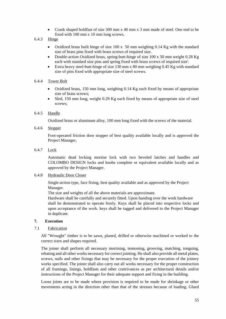
55
Crank shaped holdfast of size 300 mm x 40 mm x 3 mm made of steel. One end to be
fixed with 100 mm x 10 mm long screws.
6.4.3 Hinge
Oxidized brass built hinge of size 100 x 50 mm weighing 0.14 Kg with the standard
size of brass pins fixed with brass screws of required size.
Double-action Oxidized brass, spring-butt-hinge of size 100 x 50 mm weight 0.28 Kg
each with standard size pins and spring fixed with brass screws of required size'.
Extra heavy steel-butt-hinge of size 130 mm x 80 mm weighing 0.45 Kg with standard
size of pins fixed with appropriate size of steel screws.
6.4.4 Tower Bolt
Oxidized brass, 150 mm long, weighing 0.14 Kg each fixed by means of appropriate
size of brass screws;
Sled, 150 mm long, weight 0.29 Kg each fixed by means of appropriate size of steel
screws;
6.4.5 Handle
Oxidized brass or aluminum alloy, 100 mm long fixed with the screws of the material.
6.4.6 Stopper
Foot-operated friction door stopper of best quality available locally and is approved the
Project Manager,
6.4.7 Lock
Automatic dead locking mortise lock with two beveled latches and handles and
COLOMBO DESIGN locks and knobs complete or equivalent available locally and as
approved by the Project Manager.
6.4.8 Hydraulic Door Closer
Single-action type, face fixing, best quality available and as approved by the Project
Manager.
The size and weights of all the above materials are approximate.
Hardware shall be carefully and securely fitted. Upon handing over the work hardware
shall be demonstrated to operate freely. Keys shall be placed into respective locks and
upon acceptance of the work. keys shall be tagged and delivered to the Project Manager
in duplicate.
7. Execution
7.1 Fabrication
All "Wrought" timber is to be sawn, planed, drilled or otherwise machined or worked to the
correct sizes and shapes required.
The joiner shall perform all necessary mortising, tennoning, grooving, matching, tonguing,
rebating and all other works necessary for correct jointing. He shall also provide all metal plates,
screws, nails and other fixings that may be necessary for the proper execution of the joinery
works specified. The joiner shall also carry out all works necessary for the proper construction
of all framings, linings, holdfasts and other contrivances as per architectural details and/or
instructions of the Project Manager for their adequate support and fixing in the building.
Loose joints are to be made where provision is required to be made for shrinkage or other
movements acting in the direction other than that of the stresses because of loading. Glued

56
joints are to be used where provision need not be made for shrinkage or other movements in
the connection, and where sealed joints are required. All glued joints shall be cross-longed or
otherwise reinforced. All nails, springs etc. shall he punched and puttied. All cutting edges of
tools shall be sharp to avoid burnishing.
All wood work, as fat- as practicable, shall be assembled in shop, finished and prime coated
before delivery for fixing. In addition to machine sanding, all woodwork shall be smoothed by
hand using "00" sand paper to have the required smooth surface, free from machine and tool
marks, abrasions, raised grains and other defects. All wood work shall be fitted to plaster and
other finished work in a careful manner so as not to injure these surfaces. Where plaster or other
work is damaged or disturbed, it shall be restored to its original state by the Contractor at no
additional cost.
All wood work shall be neatly finished to the exact dimensions specified. All nails and screws
shall be of approved type. Hammer shall not be used for driving in or starting in the screws. All
screws shall be dipped in oil before they are inserted in the wood. The heads of nails or screws
shall be sunk and puttied or dealt with as directed by the Project Manager.
7.2 Priming
Where priming is specified, the timber shall be coated with a thick mixture of red or white lead
and linseed oil. The Contractor shall provide for priming and touching up primer where
necessary during the progress of work.
7.3 Door frames
The door frames shall be secured in place by means of corrugated anchors of non-ferrous metal
or galvanized ferrous metal bent up against the back of the jambs and screwed in place and built
into the masonry as it is being constructed. There shall be one such anchor near the top and
bottom of each jamb at not over 900 mm intervals between the top and bottom anchors. Frames
shall be secured to the anchors by means of 9 mm diameter bolts or screws extending through
the frames, beads of bolts or screws shall be countersunk and covered with the stops, which
shall be screwed in place.
7.4 Door Jamb & Door Shutters
1. Door Jamb in GI sheets of 146swg
2. Door shutters:
a) Solid wood – too expensive
b) Flush doors made of plywood and veneer.
7.5 Flush Door
Providing and fixing 1-½" thick wooden flush doors with solid core with approved HDF
MOULDED facing skin on both sides of the shutter, with matching hot Pressed PVC
lipping on all sides of the door shutters, including 5" x 2" G.I (16 gauge) door frame,
Complete in all respects.
Standard Sizes: 3' 6" x 7' 0"
3' 0" x 7' 0"
2' 6" x 7' 0"
7.4 Fitting Door Shutters
All the doors shall be fitted, hung and trimmed as hereinafter specified and as indicated on
the Drawings.

57
Doors shall have a clearance, of 4 mm at sides and top unless otherwise directed by the
Project Manager and shall have 20 mm clearance at bottom. All the doors having a
thickness of 44 mm or more shall have the lock or latch edge beveled at the rate of 3.0 mm
in 50 mm. Doors shall be hung and trimmed with hardware as specified. All the locks shall
be installed at the same height. Knob locks and knob latches shall be located at height as
directed by the Project Manager. Door locks shall have the center of the locks at the same
height as the center of the knob locks.
8. Measurement and Payment
8.1 General
Except otherwise specified herein or elsewhere in the Contact documents, no measurement
and payment will be made for the under mentioned specified work related to the relevant
items of the bill of quantities. ‘The cost thereof shall be deemed to have been included in
the quoted unit rate of the respective items of the Bill of Quantities.
8.1.1 All finished hardware fittings in carpentry and joinery works.
8.1.2 Glass and glazing including other materials and accessories required for installation and
finishing.
8.1.3 Prime coat, painting and wax polish in carpentry and jointry works.
8.1.4 Ant termite treatment to wood works.
8.1.5 Adhesives.
8.1.6 M.S. steel plate, non-shrink grout, teak wood plank, rough wood, sleeve, lead caulking
polishing and painting and as shown on drawings.
8.2 Measurement
Measurement of acceptably completed quantity of all types of polished wood works will
be made on the basis of net actual area in sq.ft. meter, fabricated and installed in position
as shown on the drawings or as directed by the Project Manager.
8.3 Payment
Payment will be made for acceptably measured quantity of all types of wood works on the
basis of unit rate per sq.ft. meter quoted in the bill of quantities and shall constitute full
compensation for all the work related to the item.
8.4 Door Jamb & Door Shutters
3. Door Jamb in GI sheets of 146swg
4. Door shutters:
c) Solid wood – too expensive
d) Flush doors made of plywood and veneer.
Flush Door
Providing and fixing 1-½" thick wooden flush doors with solid core with approved HDF
MOULDED facing skin on both sides of the shutter, with matching hot Pressed PVC lipping on
all sides of the door shutters, including 5" x 2" G.I (16 gauge) door frame, Complete in all
respects.
Standard Sizes: 3' 6" x 7' 0"
3' 0" x 7' 0"
2' 6" x 7' 0"

58
SECTION-6 TERRAZZO WORK
1. Scope of Work
The work covered by this section of the specifications, consist of furnishing all plant, labour,
equipment, appliances and materials and in performing all operations complete in strict accordance
with this section of the specifications and the applicable drawings and subject to the terms and
conditions of the contract. The work under the section includes the followings:-
a) Precast terrazzo tiles flooring
b) In situ terrazzo flooring
c) Terrazzo Dado and Skirting
d) Terrazzo on stairs
e) Terrazzo finished precast partitions for Toilets
2. Applicable Standard
Unless otherwise specified, terrazzo work shall be in conformity with British standard Code
of Practice C.P. 204 In Situ Flooring Part 1, 'General' and Part 3. "Terrazzo Flooring" as applicable
to the work shown on the drawings and specified in the Bill of Quantifies.
3. Materials
3.1 Cement. Sand, Aggregate and Water for Concrete shall conform to specification
for "Plain and Reinforced Concrete".
3.2 Marble Chips shall be crushed marble and shall be best quality white or coloured
sound and hard local marble chips approved by the Project Manager and of the as
mentioned in the Bill of Quantities or as required by the Project Manager.
3.3 Dividing Strips shall be glass, brass or marble strips 4-5 mm thick and 1-1/2"
wide or as specified in the Bill of Quantities.
3.4 Angle Clips for precast toilet partitions shall be chromium plated steel or stainless
steel clips as shown on drawings.
3.5 Bolts of precast toilet partitions shall be 5/16" inch bars bolts chrome-plated, with
acron heads, fitted to wall anchors.
3.6 Terrazzo Tiles Terrazzo tiles shall be first grade, mechanically compressed type
conforming to PS-531. Tiles shall be 12"x12"x0.88" / 30.0x30.0x2.2cm with a
toping of 0.4" or 10.00mm thickness composed of 1:2 cement & marble chips.
The base being 1:3 cement mortar. The colour, quality and size of chips shall be
as per Project Manager's approval.
Cleaning Compound: The Compound used for all cleaning of terrazzo shall be
an approved neutral chemical cleaner free from acid and alkali or any other material that will affect
the colour or otherwise damage the Terrazzo and shall not affect the conductivity of terrazzo floors.
4. Samples
All materials used for Terrazzo and marble work as well as samples of terrazzo floor and
marble work shall be submitted to the Project Manager and his approval obtained. Same materials
should also be tested and this shall be got done by the Contractor at his own expense from a
Laboratory approved by the Project Manager.

59
5. Execution
5.1 In Situ Terrazzo Flooring
The floor shall consist of a wearing surface to consistency and net thickness as specified in Bill of
Quantities, laid over 1:2:4 under bedding concrete of the specified thickness. The net uniform
thickness specified for wearing surface shall be that obtained after grinding and polishing. The 1:2:4
concrete shall be mixed and laid in the manner specified for cement concrete floor using a minimum
quantity of water.
The concrete shall be leveled with a trowel and straight edge consolidated and finished with steel
trowels to an even but rough surfaces. The top layer of cement and marble chips mixed in the
proportion of 1:2 (1 cement and 2 marble chips) shall be laid over it within 12 hours. The cement
and marble chips must be mixed dry in such quantities that are sufficient for a unit area of one
specified shade. Water shall be added to only such quantities that can be mixed thoroughly and
consumed in less than 30 minutes, the quantity of water being the minimum for workability.
Mixing must to be done on water tight platform and any mix not used within 30 minutes shall be
discarded and removed from the Site. A layer of cement and marble chipping mixture should be
well troweled into the surface of the base concrete before filling to the top level of the screeds. The
layer should be well compacted and all voids shall be filled in. A layer of neat cement, of the
specified colour shall then be well-troweled into a plain smooth surface. Floors shall be laid in
panels of sizes as shown on drawings and in Bill of Quantities or as directed by the Project Manager.
Dividing strips, as specified shall be provided and fixed to exact levels making an allowance for
grinding.
Three days after laying, the top layer must be evenly and smoothly machine ground with
Carborundum blocks of coarse, medium and fine grades so as to ensure that all marble chipping are
evenly exposed all over the surface.
If marble chips are not evenly exposed the Contractor shall pull down the sin face and relay it at his
own cost. The surface after grinding shall be left undisturbed and cured for 2 to 3 weeks after which
it shall be cleaned of dirt and dust gently by rubbing with pumice stone or washing soda in sufficient
water. Three days after the surface has been cleaned, it shall be rubbed hard with 1:10 solution of
oxalic acid using fell. The surface shall then be cleaned and washed with plenty of water. After the
surface has dried a final gloss shall be given by polishing surface to the satisfaction of the Project
Manager.
5.2 Terrazzo Dado & Skirting
marble chips and cement shall conform to specifications for floor. Mixing shall be done in the same
manner and proportion. The plastered surface over which the dado/skirting is to be applied shall be
well roughened and watered, cement mortal of specified ratio shall then be plastered over this well
roughened surface to indicated thickness. Before the base course had set, the layer of terrazzo
mixture of the specifications for flooring shall be well troweled into the surface of the base to a
thickness which after, grinding shall result in the finished thickness as per Bill of Quantities. A
layer of neat cement of the specified colour shall then he well troweled into the surface leaving a
plain smooth surface. After 24 hours the Contractor shall start finishing as for floors specified
above, Terrazzo skirting shall be provided around all terrazzo floors unless otherwise shown.
Skirting and dado shall be straight, level and in plumb. Intersections at floors shall be straight and
flush. They shall be with 1/4 radius coved at floor unless otherwise shown.
5.3 Terrazzo on Stairs
The stair risers and treads shall be finished according to exact sizes including the terrazzo making
allowance for grinding of terrazzo.

60
5.4 Terrazzo Finished Precast Partitions of Urinals
Partitions walls of urinals shall be precast R.C.C. slabs finished will) l/'l" thick polished terrazzo on
both faces. The finished thickness of these walls shall be 3" or as shown on drawings and BOQ
R.C.C. slab shall conform to the specification for "Concrete" and terrazzo as per this section. Fixing
of these partitions of floor walls. etc. shall be as directed by the Project Manager and as shown on
Drawings.
5.5 Terrazzo Tile Works
The terrazzo tiles will be laid to the required levels and grades over a bedding of cement mortar
comprising of 1 part of cement and 3 parts of sand by volume. I thickness of cement sand bedding
screed shall be as per Bill of Quantities.
The curing period of the bedding shall be as directed by the Project Manager. As large an area of
bedding shall be spread at one time as can be covered with tiles before the mortar has set. Surplus
mortar shall be removed. The thickness of bedding in any space shall not be less than 1/2" / 12.5mm.
Floor and wall surfaces to receive the tiles shall be thoroughly cleaned of all dirt, dust, oil and other
objectionable matters. Tiles shall be laid out from the Centre line of each space in an outward
direction and the pattern should be made symmetrical with a minimum number of cut tiles. Joints
between the tiles shall be of uniform width. Tiles shall be cut with a suitable cutting tool and rough
edges shall be pumice stone. Tiles shall be laid to the straight edges.
After seven days the terrazzo tile floors shall be machine ground to a true even surface using various
grades of abrasive stones as required and directed by the Project Manager. After the first grinding
the floor shall be grouted with the same colour composition as used for its manufacture. The grout
shall be of the consistency of thick cream and shall be brushed over the floor to fill in the joints and
after 72 hours the grouting coat shall be removed by grinding till a smooth and even surface is
obtained. Area and portion of the floor inaccessible for the grinding machine shall be ground and
rubbed by hand. The final gloss shall be given by polishing the surface to the satisfaction of the
Project Manager.
The tiled floor shall be kept wet for at least 72 hours and no one should be
allowed to walk on the tiles during that period.
6. Measurements and Payments
6.1 General
Except otherwise specified herein or elsewhere in the contract Documents, no measurement and
payment will be made for the under mentioned specified works related to the relevant items of the
Bill of Quantities. The cost thereof shall be deemed to have been included in the quoted unit rate
of the respective items of the Bill of Quantities.
6.1.1 Grinding, washing polishing and finishing of Terrazzo work.
6.1.2 Under bedding and screening.
6.1.3 Preparation of concrete surface for Terrazzo works.
6.1.4 Cement concrete base.
6.2 Measurement
Measurement of acceptable completed works of Terrazzo Flooring, Dado,
Skirting. Treads, Risers etc., will be made on the basis of number of sq. ft. / square meter
provided & installed in position as shown on the drawing or as directed by the Project Manager.

61
6.3 Payment
Payment will be made for acceptable measured quantify of Terrazzo Work on the
basis of unit rates per.sq.ft / square meter quoted in the Bill of Quantities & shall constitute full
compensation for all the works related to the items.

62
SECTION-7 CERAMIC TILES
Part 1 - General
1. Section Includes
A. Scope: Ceramic Tile Finishes.
1. Floor Finishes
a. Unglazed ceramic floor tiles.
b. Rectified ceramic tiles.
c. Porcelain tiles:
d. Porcelain fittings for staircases.
e. Quarry tiles.
2. Wall Finishes
a. Ceramic tiles for walls.
b. Porcelain tiles for walls:
3. Tile fittings.
4. Stone thresholds installed as part of tile installations.
B. Coordination
1. Do not install ceramic tile finishes until predecessor construction activities in spaces are
completed and ambient temperature and humidity conditions are being maintained to
comply with referenced Standard Specifications and manufacturer's written instructions.
2. The works of ceramic tile finishes have to be coordinated with the works cement sand
screeds specified under section and with mechanical and electrical works.
C. Refer to the Schedules at the end of Part 3 of this Section for setting main details.
2 Submittals
A. General
Contractor shall prepare and submit to the approval of Engineer the submittals listed here after in
this Article in accordance with requirements of Conditions of the Contract and Section “Submittal
Procedures”.
B. Action Submittals:
1. Qualification Data: For manufacturers of tiles, adhesives and grouts.
2. Product Data: For each type of tile, mortar, grout, and other products specified.
a. Include in product data submittal reports of test conducted by third party testing agency
to demonstrate compliance of submitted product with specified requirements. Test reports
shall not be dated more than one year old.
3. Shop Drawings: For the following:
a. Tile patterns and locations.
63
b. Widths, details, and locations of expansion, contraction, control, and isolation joints in
tile substrates and finished tile surfaces.
c. Details of interface with adjoining floors.
d. For wall tiles installed to Tile backing gypsum board panels or cement boards, included
calculations to proof that over-turning of tile and substrate will not occur.
4. Tile Samples for Initial Selection: Manufacturer's color charts consisting of actual tiles or
sections of tiles showing the full range of colors, textures, and patterns available for each type and
composition of tile indicated. Include Samples of accessories involving color selection.
5. Grout Samples for Initial Selection: Manufacturer's color charts consisting of actual sections
of grout showing the full range of colors available for each type of grout indicated.
6. Samples for Verification: Of each item listed below, prepared on Samples of size and
construction indicated. Where products involve normal color and texture variations, include Sample
sets showing the full range of variations expected.
a. Each type and composition of tile and for each color and texture required, at least 300
mm square, mounted on braced cementitious backer units, and with grouted joints using
product complying with specified requirements and approved for completed work in color
or colors selected by Engineer.
b. Full-size units of each type of trim and accessory for each color required.
c. Stone thresholds in 150-mm lengths.
7. Master Grade Certificates: For each shipment, type, and composition of tile, signed by tile
manufacturer and Installer.
C. Informational Submittals:
1. Product Certificates: Signed by manufacturers certifying that the products furnished comply
with requirements.
2. Installer Experience: List of five projects (minimum) of a similar nature carried out successfully
by the installer with the same product.
3. Qualification Data: For firms and persons specified in the "Quality Assurance" Article to
demonstrate their capabilities and experience. Include lists of completed projects with project
names and addresses, names of engineers and employers, and other any information required by
Engineer.
4. Setting Material Test Reports: Indicate and interpret test results for compliance of tile setting
and -grouting products with specified requirements.
5. Cleaning and maintenance data for inclusion in Project’s Operation and Maintenance Manual.
1. Provision 404.02 - Low Emitting Materials: Adhesives and Sealants: Submit material
datasheet and other documents as detailed in page 134 of Document 2 that proof the ceramic
adhesives used in the project have Volatile Organic Compounds (VOC) content within the
limits.
2. Provision 701.07 - Regional Materials: Submit material datasheet and other documents
as detailed in page 303 of Document 2 that proof the ceramic tiles (where applicable) and
the ceramic adhesives used in the project are Regional Material as defined in page 31 of
Document 1 and may be included in the monetary 5% for Regional Materials stipulated in
the Provision 701.07, page 73 of Document 1.

64
3 Quality Assurance
A. Regularity Requirements: The works under this Section shall comply with requirements as
applicable to this Project, unless otherwise more stringent requirements are specified throughout
this Section.
B. Quality System: Provide the products of a manufacturer holding valid ISO 9001 certification.
C. Compliance Standards
The work of suspended gypsum board ceilings shall comply with the requirements of the Standard
Specifications referenced in this Section.
D. Product Tests: Test reports obtained from manufacturer for tests run by a qualified independent
testing agency, or third-party-witnessed in-house testing with calibrated test equipment’s to
demonstrate compliance of submitted ceramic tiles with dimensional and mechanical properties
specified in this Sections. Section should have been conducted within maximum one year before
date of submission, otherwise contractor will be requested to conduct pre-construction testing to
proof the same at no extra cost. Tests should also have been run on samples obtained from the
production of the factory or production unit producing ceramic tiles submitted for this project.
E. Installer Qualifications: Engage an experienced installer who has completed tile installations
similar in material, design, and extent to that indicated for this Project and with a record of
successful in-service performance.
F. Testing Agency Qualifications: An independent testing agency, acceptable to Engineer and
qualified according to ASTM E 329 to conduct the testing indicated.
G. Source Limitations for Tile: Obtain each color, grade, finish, type, composition, and variety of
tile from one source with resources to provide products from same production run for each
contiguous area of consistent quality in appearance and physical properties.
H. Source Limitations for Setting and Grouting Materials: Obtain ingredients of a uniform
quality for each mortar, adhesive, and grout component from a single manufacturer and each
aggregate from one source or producer.
I. Pre-installation Meeting: Conduct meeting at Project site to comply with requirements of
"Project Meetings. Coordinate the work of ceramic tile with the work of other trades.
4. Mockups
A. Before installing ceramic tile, construct mockups, in accordance with requirements of “Quality
Requirements”. to verify selections made under Sample submittals and to demonstrate aesthetic
effects and qualities of materials and execution. Build mockups to comply with the following
requirements, using materials indicated for completed Work.
1. Build mockups for each form of ceramic tile construction and finish required.
2. Approved mockups in an undisturbed condition at the time of erecting subsequent work items
may become part of the completed Work.
5 Delivery, Storage, and Handling
A. Deliver and store packaged materials in original containers with seals unbroken and labels intact
until time of use. Comply with requirement of referenced Standard Specifications for labeling
sealed tile packages.
B. Prevent damage or contamination to materials with water, foreign matter and soil, and other
causes.

65
C. Compliance Standards: The work of suspended gypsum board ceilings shall comply with the
requirements of the Standard Specifications referenced in this Section.
D. Product Tests: Test reports obtained from manufacturer for tests run by a qualified independent
testing agency, or third-party-witnessed in-house testing with calibrated test equipment to
demonstrate compliance of submitted ceramic tiles with dimensional and mechanical properties
specified in this Sections. Section should have been conducted within maximum one year before
date of submission, otherwise contractor will be requested to conduct pre-construction testing to
proof the same at no extra cost. Tests should also have been run on samples obtained from the
production of the factory or production unit producing ceramic tiles submitted for this project.
E. Installer Qualifications: Engage an experienced installer who has completed tile installations
similar in material, design, and extent to that indicated for this Project and with a record of
successful in-service performance.
F. Testing Agency Qualifications: An independent testing agency, acceptable to Engineer and
qualified according to ASTM E 329 to conduct the testing indicated.
G. Source Limitations for Tile: Obtain each color, grade, finish, type, composition, and variety of
tile from one source with resources to provide products from same production run for each
contiguous area of consistent quality in appearance and physical properties.
H. Source Limitations for Setting and Grouting Materials: Obtain ingredients of a uniform
quality for each mortar, adhesive, and grout component from a single manufacturer and each
aggregate from one source or producer.
I. Pre-installation Meeting: Conduct meeting at Project site to comply with requirements of
Section "Project Meetings. Coordinate the work of ceramic tile with the work of other trades.
Part 2 - Products
A. Proposed Manufacturers: Subject to compliance with Specifications and other Contract
Documents, the following manufacturers are proposed for consideration of Contractor as offering
products that may be incorporated into the Work:
1. Ceramic Tiles Manufacturers:
a. Equal and approved unnamed manufacturer.
2. Ceramic Tiles Suppliers:
f. Unnamed Supplier who provides equal and approved product.
3. Setting and Grouting Materials Manufacturers:
a. Equal and approved unnamed manufacturer.
1. Products General
A. Ceramic Tile Standard: Provide tile that complies with the following standard specification:
1. EN ISO 13006.
2. Provide highest quality grade (First or Master) in manufacturer’s range.
B. Standards for Tile Installation Materials: Provide materials complying with ANSI Standards
referenced in "Setting Materials" and "Grouting Materials" articles.
C. Colors, Textures, and Patterns: Where manufacturer's standard products are indicated for
tile, grout, and other products requiring selection of colors, surface textures, patterns, and other
appearance characteristics, provide specific products or materials complying with the following
requirements:

66
1. Submit samples selected based on Material Selection Sheets.
2. Provide materials that match the samples that have been approved by Engineer.
3. Provide tile trim and accessories that match color and finish of adjoining flat tile and approved
by Engineer.
D. Factory Blending: For tile exhibiting color variations within the ranges selected during Sample
submittals, blend tile in the factory and package so tile units taken from one package show the same
range in colors as those taken from other packages and match approved Samples.
E. Mounting: Where factory-mounted tile is required, provide back- or edge-mounted tile
assemblies as standard with manufacturer, unless another mounting method is indicated.
1. Where tile is indicated for installation in wet areas, do not use back- or edge-mounted tile
assemblies unless tile manufacturer specifies in writing that this type of mounting is suitable for
these kinds of installations and has a record of successful in-service performance.
2. Floor Tiling
A. Fully Vitrified Stoneware (Porcelain) Floors Tiles: Extremely compact-body impervious
paver tiles, homogenous throughout the thickness fabricated in the dust-pressed method from clay
mixed with Kaolin, quartz and feldspar or other porcelain mix and vitrified with lowest porosity
through cycles of high-temperature firing in roller kilns. Stoneware tiles are to be manufactured to
EN ISO 13006 Group B1a (E ≤ 0.04%) tiles and meet the requirements specified here after. Use of
tiles to any other ISO-13006 Grade is not acceptable:
1. Characteristics:
a. Dimension: As indicated on Drawings and Finish Schedule.
b. Nominal Thickness: Minimum 10 mm excluding keying ribs.
c. Surface Condition: Plain with matt finish for floors.
d. Color and Pattern: Match basis of design product.
e. Back Condition: Raised pattern for keying.
f. Edge Condition: Square.
2. Performance Properties:
a. Bending Resistance: 27 N/mm2 to ISO 10545.4.
b. Abrasion Resistance: 205 mm3 to ISO 10545.6.
c. Surface Hardness Mohs Resistance: 6.
d. Resistance Against Chemical Agents: Unaffected to ISO 10545.13.
e. Liner Thermal Expansion Coefficient: 9 MK-1 to ISO 10545.9.
f. Stain Resistance: Resistant to ISO 10545.14.
Skid Resistance: 0.60 Wet Rubber or Dry Leather, B.C.R. test method, matt tiles.
g. Color Stability: No change in brightness or color to DIN 51094.
3. Dimensional Tolerances: Tiles shall be tested to UNI EN ISO and meet requirements of EN
ISO 13006.
B. Unglazed Ceramic Floor Tiles: Are to be manufactured to EN ISO 13006 group B1b (0.5% E≤
3%) tiles and meet the following requirements:
1. Characteristics:
a. Manufacture: Dust pressed, burning to verification.
b. Composition: White ware, ceramic mix.
c. Size: As indicated on Drawings and Finish Schedule.

67
d. Nominal Thickness: Minimum 8.00 mm excluding keying ribs.
e. Surface Finish: Unglazed.
f. Color and Pattern: Match basis of design product.
g. Back Condition: Raised pattern for keying.
h. Edge Condition: Square.
2. Performance Properties:
a. Bending Resistance: 27 N/mm2 to ISO 10545.4.
b. Abrasion Resistance: 205 mm3 to ISO 10545.6.
c. Surface Hardness: 6.
d. Resistance against Chemical Agents: Unaffected to ISO 10545.13.
-1 to ISO 10545.9
f. Stain Resistance: Resistant to ISO 10545.14.
g. Skid Resistance: 0.60 Wet Rubber or Dry Leather, B.C.R. test method, matt tiles.
h. Color Stability: No change in brightness or color. to DIN 51094.
3. Dimensional Tolerances: Tiles shall be tested to UNI EN ISO and meet requirements of EN
ISO 13006.
Rectified Ceramic Floor Tiles: Locally produced extra thick ceramic floor tiles complying with
EN ISO 13006 Group B1b (0.5% < E ≤ 5%). Tiles shall be of pebble pattern on top surface with
abrasive content.
1. Impact resistance to BS EN 10545, highest grade.
2. Skid Resistance: 0.60 Wet Rubber or Dry Leather, B.C.R. test method, matt tiles.
3. Pattern: Pebble pattern.
4. Metal Oxide: For coloring.
5. Thickness: 13 mm, minimum.
6. Size: As indicated on Drawings and Finish Schedule or selected by Engineer.
D. Porcelain Fittings for Staircases:
Fittings for stair and step finishes are to be ready-to-set fittings inclusive of formed nosing and
linear grooves designed to increase slip resistance. Surface finish is to be chemically treated matt
surface for slip resistance
1. Characteristics:
a. Thickness: Not less than 10 mm.
b. Surfaces Features: Acid-resistant, antibacterial, non-slip and wear resistant.
c. Edges: Square.
d. Style: Rustic Tiles.
e. Color: As selected by Engineer from manufacturer’s full range of colors.
2. Physical Properties:
a. Water Absorption: Maximum 0.5 % according to EN ISO 10545.3.
b. Breaking Strength: Not less than 1300 N according to EN ISO 10545.4.
c. Modulus of Rupture: Minimum 35 Mpa according to EN ISO 10545.4.
10545.6.
e. Thermal Shock Resistance: Fully resistant according to EN ISO 10545.9.
f. Resistance Against Chemical Agents: Unaffected according to En ISO 10545.13
g. Slip Resistance: According to DIN 51130.
3. Fittings Components:

68
a. Step Tile: Matt Surface with Grooves, and of dimension as selected by Engineer from
manufacturer’s ranges.
b. Size of Face Plate: As selected by Engineer from manufacturer’s ranges.
4. Size of Tradition Tile for Landings: As selected by Engineer from manufacturer’s range.
E. Quarry Tiles and Fittings: Shall be heavy duty tiles, and fittings of color through body
(homogenous throughout the thickness) fabricated in extrusion process, and burnt to above-red
heat, from natural clay blend or shale with inclusion of abrasive aggregated of silicone carbide,
aluminium oxide or other rustproof abrasive of comparable hardness in the wearing surface.
Quarry tiles are to be manufactured to ANSI A 137.1 and meet the following requirements.
1. Characteristics:
a. Size: As shown on Drawings.
b. Nominal Thickness: 16.00 mm, minimum for tiles and 12.50 mm for trim units,
minimum.
c. Edge Condition: Square.
d. Surface Condition: Plain and unglazed.
e. Back Condition: Of raised or depressed pattern.
f. Color: As selected by the Engineer from manufacturer’s standard range.
2. Provide straight or coved bases as indicated on finish schedule for each type.
3. Performances
a. Water Absorption: Not exceeding 5% to ASTM C 373.
b. Breaking Strength: 250 pounds average to ASTM C 648.
c. Abrasive Hardness: Index of 35 or greater to ASTM C 501.
d. Bond Strength: Greater than 3.5 kg/cm2 ASTM C 482.
3. Wall Tiles
A. Glazed Ceramic Wall Tiles: Are to be manufactured to EN ISO 13006 group B 2a (3% < E ≤
6%) tiles and meet the following requirements:
1. Characteristics:
a. Manufacture: Dust pressed, burning to verification.
b. Composition: White ware, ceramic mix.
c. Size: As indicated on Drawings and Finish Schedule.
d. Nominal Thickness: Minimum 6.00 mm excluding keying ribs.
e. Surface Finish: Glazed.
f. Color and Pattern: Match basis of design product.
g. Back Condition: Raised pattern for keying.
h. Edge Condition: Square or cushioned, to match design product.
2. Performance Properties:
a. Bending Resistance: 27 N/mm2 to ISO 10545.4.
b. Abrasion Resistance: 205 mm3 to ISO 10545.6.
c. Surface Hardness: 6.
d. Liner Thermal Expansion Coefficient: 9 MK-1 ISO 10545.9
e. Stain Resistance: Resistant to ISO 10545.14
f. Color Stability: No change in brightness or color to DIN 51094

69
3. Dimensional Tolerances: Tiles shall be tested to UNI EN ISO and meet requirements of EN
ISO 13006.
4. Glass Mosaics
A. Glass Mosaics: Are to comply with the following requirements:
1. Classification: Crystal glass.
2. Pattern: Square tiles, opaque solid color.
3. Thickness: 3 mm, minimum.
4. Surface Texture: Smooth and flat.
5. Edges: Sharp not cushioned.
5. Tile Fittings
A. General: Same material and method of manufacture as for adjoining tiles.
B. Grade: Highest in manufacturer’s range.
C. Types: As indicated on Drawings:
1. Cove base.
2. Internal and external corner fittings.
3. Other types as indicated on Drawings.
6. Stone Thresholds
A. General: Provide stone thresholds that are uniform in color and finish, fabricated to sizes and
profiles indicated to provide transition between tile surfaces and adjoining finished floor surfaces.
B. Fabricate thresholds to thickness indicated, but not more than 12.7 mm above adjoining finished
floor surfaces, with transition edges beveled on a slope of no greater than 1:2.
C. Marble Thresholds: Provide marble thresholds complying with ASTM C 503 requirements and
with a minimum abrasive-hardness value of 10 per ASTM C 241. Match Engineer's approved
sample for color and finish.
D. Granite Thresholds: Provide granite thresholds complying with ASTM C 615 requirements.
Match Engineer's approved sample for color and finish.
7. Setting and Grouting Materials
A. Prepackaged Setting Mortar: Proprietary factory-prepared blend of carefully selected raw
materials, Portland cement and graded aggregates which is manufactured for use with latex mortar
admixture to produce a latex Portland cement mortar of the following properties:
1. Service Rating to ASTM C 627: Extra heavy.
2. Water Absorption: Not more than 5 % when tested to test method referred to in ANSI A 118.4-
6.1.
3. Compressive Strength: Minimum 34.00 MPa at 28 days when tested to ANSI A118.4-6.1.
4. Pot life: Not less than 1.00 hour.
5. Time to foot Traffic: Not more than 12 hours.
6. Time to Heavy Traffic: Not more than 72 hours
B. Latex-Portland Cement Adhesive (Thin Set Mortar): ANSI A118.4 of the following
compositions:

70
1. Prepackaged dry-mortar mix containing dry, re dispersible, ethylene vinyl acetate additive to
which only water must be added at Project site.
2. Prepackaged dry-mortar mix combined with acrylic resin or styrene-butadiene-rubber liquid-
latex additive.
a. For wall applications, provide non sagging mortar that complies with Paragraph F-
4.6.1 in addition to the other requirements in ANSI A118.4.
3. Use for floor installation, unless other material is specified.
a. Use product of waterproofing properties. Water absorption value shall not exceed the
water absorption value of tiles set with the thin set adhesive.
C. Chemical-Resistant, Water-Cleanable, Epoxy Tile Grout: ANSI A118.3 and requirements
specified hereunder, with a VOC content of 65 g/L or less.
1. General Performance Properties:
a. Needs no sealing.
b. Recommended for exterior applications for case of joints subject to direct sun rays where
used in swimming pools and other outdoors applications.
c. Resistant to Bacteria attack.
d. Inclusive of antimicrobial protection to block growth of mold and mildew when used
with the antimicrobial protection product.
e. High chemical resistance.
2. Physical Properties:
a. Water Absorption to ASTM C-413: 0.19%, maximum.
b. Water Cleanability: Pass 80 minutes.
c. Initial Setting Time: Pass > 2.00 hours.
d. Tensile Strength ASTM C-307: 20 MPa, minimum.
e. Compressive Strength ASTM C-579: 57 MPa, minimum.
f. Modulus of Rupture ASTM C-580: 37 MPa, minimum.
g. Linear Shrinkage ASTM C-531: 0.07%, maximum.
h. Sagging Test: Pass with no change; test method E5.4 to ANSI 118.3.
i. Flexural Strength ASTM C-580: 26 MPa, minimum.
j. Service Temperature: 80°C Continuous and 182°C Intermittent, minimum.
k. Quarry Shear Bonds: 15 MPa, minimum.
l. Bond Strength to Concrete ASTM C-321: 1.00 MPa, minimum.
m. Chemical Resistant: Recommended for Intermittent exposure (3 days) to corrosive
cleaners when tested to ASTM C-267.
n. Use for tile installations (Floors) under this Section.
D. Chemical-Resistant, Water-Cleanable, and Epoxy Tile Adhesive: Epoxy adhesive designed
for the installation of large format ceramic tiles, porcelain tiles, and stone on sound concrete,
masonry and Portland cement plaster clean surfaces. The product shall be recommended for
commercial and installations of porcelain tiles of sizes indicated on Drawings and which may be

71
subject to physical abuse, shock, and mild chemicals in Interior and Exterior applications. Product
proprietary tile adhesive product complying with requirements of ANSI A118.3 and the following
Requirements.
1. Performances:
a. Fast permanent bond.
b. Water cleanable.
c. High-bond strength.
d. Non-sag consistency.
e. Low modulus consistency.
f. Solvent free.
g. Can be used in spot application.
2. Mild Chemical Resistance Performance Properties:
a. Water Absorption, ANSI A118.3-1999: 0.1%, maximum.
b. Shear Bond Strength Marble/Concrete ANSI A118.3-1999: 5.8 Mpa, minimum.
c. Compressive Strength ANSI A118.3-1999: 57.8 MPa, minimum.
d. Modulus of Elasticity ASTM-D 695: 2 x 10³.
e. Tensile Strength ASTM-D 638: 25.3 MPa.
f. Elongation ASTM D 638: 1%.
1) Use for tile installations (floors and walls) under this Section.
2) Provide non-staining white formulation.
E. Polymer Modified Cement Grout: ANSI A 118.7.
1. Polymer Type: Acrylic resin or styrene-butadiene rubber in liquid-latex form for addition to
prepackaged dry-grout mix.
2. Unsanded grout mix for joints (3 mm) and narrower.
8. Elastomeric Sealants
A. General: Provide manufacturer's standard chemically curing, elastomeric sealants of base
polymer and characteristics indicated that comply with applicable requirements of Section "Joint
Sealants."
B. Colors: Provide colors of exposed sealants to match colors of grout in tile adjoining sealed joints,
unless otherwise indicated.
9. Miscellaneous Materials
A. Sand Beds: Clean natural sand free from foreign matters and boulders or stones in any size,
graded as fine to medium coarse sand to a Standard Specifications approved by Engineer, placed
loosely, distributed and hand compacted in uniform thickness to obtain finish floor level of tile
floors indicated on Drawings.
B. Trowelable Underlayments and Patching Compounds: Latex-modified, Portland-cement
based formulation provided or approved by manufacturer of tile-setting materials for installations
indicated. Comply with requirements in Section "Hydraulic Cement-Based Underlayment".
C. Tile Cleaner: A neutral cleaner capable of removing soil and residue without harming tile and
grout surfaces, specifically approved for materials and installations indicated by tile and grout
manufacturers.
10. Metal Accessories

72
A. Dividing Strips: Shall be alloy 316 stainless steel with polished finish. Depth of divider is to
give secure anchorage into mortar bedding and to finish to exact level of floor.
1. Thickness: 6.00 mm.
B. Metal Beads: Proprietary metal fittings, high quality produced for use in decorative applications,
extruded aluminum alloy and temper 6063T5 and scratch-resistant colored polyester powder
coating. Install one integral piece for each application.
1. Use for external corners and other locations where ceramic fittings are not indicated on Drawings
or directed by Engineer.
2. Size as approved by Engineer.
C. Divider Strips and Edging: Metal or combination of metal and neoprene base, designed
specifically for flooring applications, in longest lengths available, and as follows:
1. Exposed-Edge Material: Stainless steel; ASTM A 666, Type 316 or better.
2. Cross-Section Profile: Angle or L-shape.
3. Height: Equal to stone thickness plus depth of setting bed.
4. Width: 10 mm.
5. Control-Joint Filler: Neoprene, in color selected by Engineer from manufacturer's full range.
6. Extent: Extent Use combination metal\neoprene for movement and control joints through ceramic
floor tiles as stipulated by requirements of referenced installation standards.
D. Accessories for Thick Set Mortar Installation:
1. Reinforcing Wire Fabric: Galvanized, welded wire fabric, 50.8 by 50.8 mm by 1.57-mm
diameter; comply with ASTM A 185 and ASTM A 82 except for minimum wire size.
a. Use reinforcing wire fabric for installations over compressible thermal insulating materials.
2. Expanded Metal Lath: Diamond-mesh lath complying with ASTM C 847. Use for reinforcing
separations between dissimilar backgrounds if wall tile is set with thick wet mortar bedding.
a. Base Metal and Finish for Interior Applications: Uncoated or zinc-coated (galvanized)
steel sheet, with uncoated steel sheet painted after fabrication into lath.
1) Configuration over Solid Surfaces: Self-furring.
2) Weight: 0.7 kg/sq. m.
11. Mixing Mortars and Grout
A. Mix mortars and grouts to comply with referenced standards and mortar and grout manufacturers'
written instructions.
B. Add materials, water, and additives in accurate proportions.
C. Obtain and use type of mixing equipment, mixer speeds, mixing containers, mixing time, and
other procedures to produce mortars and grouts of uniform quality with optimum performance
characteristics for installations indicated.
Part 3 - Execution
1 Examination
A. Examine substrates, areas where tile will be installed for compliance with requirements for
installation tolerances and other conditions affecting performance of installed tile. Curing may also
be achieved through use of plastic sheets.

73
1. Verify that substrates for setting tile are firm; dry; clean; free from oil, waxy films, and curing
compounds; and within flatness tolerances required by referenced ANSI A108 series of tile
installation standards for installations indicated.
2. Verify that installation of grounds, anchors, recessed frames, electrical and mechanical units of
work, and similar items located in or behind tile has been completed before installing tile.
3. Verify that joints and cracks in tile substrates are coordinated with tile joint locations; if not
Coordinated, adjust latter in consultation with Engineer.
B. Do not proceed with installation until unsatisfactory conditions have been corrected.
2. Preparation
A. Remove coatings, including curing compounds, and other substances that contain soap, wax, oil,
or silicone and are incompatible with tile-setting materials by using a terrazzo or concrete grinder,
a drum sander, or a polishing machine equipped with a heavy-duty wire brush.
B. Provide concrete substrates for tile floors installed with dry-set or latex-Portland cement mortars
that comply with flatness tolerances specified in referenced standard for tile installation.
1. Use trowelable leveling and patching compounds per tile-setting material manufacturer's written
instructions to fill cracks, holes, and depressions.
2. Remove protrusions, bumps, and ridges by sanding or grinding.
C. Provide substrates for wall tile installed with dry-set or latex-Portland cement mortars that
comply with flatness tolerances specified in referenced ANSI A108 series of tile installation
standards for installations indicated.
1. Use cement plaster, with expanded mesh reinforcement where necessary, and patching
compounds per tile-setting material manufacturer's written instructions to fill cracks, holes, and
depressions.
D. Blending: For tile exhibiting color variations within the ranges selected during Sample
submittals, verify that tile has been blended in the factory and packaged so tile units taken from one
package show the same range in colors as those taken from other packages and match approved.
Samples. If not factory blended, either return to manufacturer or blend tiles at Project site before
installing.
3 Installation, General
A. Tile Installation Standards: Comply with BS 5385.
B. Extend tile work into recesses and under or behind equipment and fixtures to form a complete
covering without interruptions, unless otherwise indicated. Terminate work neatly at obstructions,
edges, and corners without disrupting pattern or joint alignments.
C. Accurately form intersections and returns. Perform cutting and drilling of tile without marring
visible surfaces. Carefully grind cut edges of tile abutting trim, finish, or built-in items for straight
aligned joints. Fit tile closely to electrical outlets, piping, fixtures, and other penetrations so plates,
collars, or covers overlap tile.
D. Jointing Pattern: Lay tile in grid pattern, unless otherwise indicated. Align joints when
adjoining tiles on floor, base, walls, and trim are the same size. Lay out tile work and center tile
fields in both directions in each space or on each wall area. Adjust to minimize tile cutting. Provide
uniform joint widths, unless otherwise indicated.
E. Lay out tile wainscots to next full tile beyond dimensions indicated.

74
F. Expansion Joints: Locate expansion joints and other sealant-filled joints, including control,
contraction, and isolation joints, where indicated during installation of setting materials, mortar
beds, and tile. Do not saw-cut joints after installing tiles.
1. Locate joints in tile surfaces directly above joints in concrete substrates.
2. Prepare joints and apply sealants to comply with requirements of Section "Joint Sealants."
G. Movement Joints: Provide 10 mm wide, non-structural, intermediate movement joint in floor
tiling of all tiled areas, based on TCA handbook, extending to the full depth of the finishing layer:
1. At 9 m in any direction for ceramic tiles bedded in semi dry mix
2. At 15 m in any direction for other types of rigid floor tiles or slabs.
H. Stone Thresholds: Install stone thresholds at locations indicated; set in same type of setting bed
as abutting field tile, unless otherwise indicated.
1. Set thresholds in latex-portland cement mortar for locations where mortar bed would otherwise
be exposed above adjacent nontile floor finish.
4. Ceramic Tile Floor Installation Schedule
A. Joint Widths, General: Unless otherwise indicated elsewhere in Contract Documents or
approved on site by Engineer, install tile on floors with the following joint widths:
1. Unglazed Ceramic Floor Tiles: 3.00 mm.
2. Rectified Ceramic Tiles: 3.00 mm.
3. Porcelain Floor Tiles: 3.00 mm.
4. Quarry Floor Tiles: 3.00 mm.
B. Level of Finished Flooring, General:
Wet Areas: Set ceramic tile finished in wet areas similar to bathrooms, toilets, powders, laundries,
shower areas and the like sloped to floor drains to drain surface water. Arrange that tiles are sloped
to floor drains from the four sides.
2. Dry Areas: Set ceramic tile finishes in dry areas (other building spaces) level at the Finish Floor
Level (F.F.L.) indicated on Drawings.
C. Floorings; Bedding and Grout Details:
1. Wet Areas, Out-Flat Distribution Corridors, Commercial Areas and Heavy-Duty Applications:
Set rectified ceramic tiles, porcelain, ceramic and quarry floor tiles with thin set adhesive mortar to
cement-sand leveling screeds as specified in, Section “Cement-Based Screed”.
a. Bedding: Water cleanable epoxy-based adhesive.
b. Grout: Water cleanable epoxy-based grout
c. Contact Area: 100%.
2. Other Applications: Set ceramic tiles and porcelain, ceramic and quarry floor tiles with thick
wet mortar bedding on a layer of clean loose sand bedding uniformly and manually distributed,
leveled and compacted.
a. Bedding: Latex-modified cement-sand mortar prepared by through adding water and
mechanical mixing as per manufacturer’s instructions.
b. Grout: Latex-modified Portland-cement-based grout.

75
c. Contact Area: 100%.
D. Bases: Set all types of ceramic bases in all types of applications to walls prepared with cement
sand plastering with Latex-modified Portland cement setting adhesive. External and internal corners
are to be metered at 45 degrees.
1. Joint Width: Respect joints and widths in adjoining flooring as long as tile sizes match.
Otherwise, Joint width is to be 3.00 mm.
2. Bedding: Same as bedding material used in adjoining flooring.
3. Grout: Same as bedding material used in adjoining flooring.
4. Contact Area: 100%.
E. Stairs Finishing: Set porcelain floor tiles and fittings to smooth finished concrete stairs using
water-cleanable epoxy-based adhesive as specified. Grout joints with epoxy grout. Set bases same
as specified before.
F. Silicone Sealer: Silicone sealer to all grouted joints. Clean adjoining tile surfaces promptly.
5. Ceramic Tile Wall Installation Schedule
A. Joint Widths, General: Unless otherwise indicated elsewhere in Contract Documents or
approved on site by Engineer, install tile on Walls with joints in widths specified hereafter. Respect
joints in floors as long as interfacing dimensions of floor and wall tiles match.
1. Glazed Ceramic Wall Tiles: 3.00 mm.
2. Porcelain Wall Tiles: 3.00 mm
B. Bedding and Grouting Materials: Any used bedding or grouting material shall be certified as
non-sag.
C. Setting to Concrete and Masonry Backgrounds: Set porcelain and ceramic with either of the
following methods
1. Adhered Tile Technique: Latex-modified Portland cement setting adhesive on 15 mm thick coat
of cement sand plaster (plaster base coat) of mix proportion similar to that specified for Portland
cement plaster base coats in Section "Portland Cement Plaster" applied onto keying scratch (dash)
coat as specified in same section. Separations between dissimilar backgrounds are to be fitted prior
to plastering.
a. Thickness of Adhesive Bedding: Comply with manufacturer’s printed instructions.
b. Contact Area: 100%.
2. Back Battering Technique: Thick wet cement-sand mortar bedding on concrete and masonry
walls. Walls are to be prepared with Portland cement-sand keying spatter dash coat (scratch coat)
of mix proportions and materials same as specified in Section "Portland Cement Plaster".
Separations between dissimilar backgrounds (concrete and masonry units) are to be reinforced with
galvanized metal lath as specified in this section. Wet cure dash coat for a minimum of 48 hours.
a. Thickness of Mortar Bedding: 15-25 mm.
b. Contact Area: 100%.
D. Setting to Gypsum Backing Panels or Cement Boards: Thin-set mortar on coated glass-mat,
water-resistant gypsum backer board or cement board used as tile backing panels:
1. Bedding: Thin-Set Mortar: Latex-modified, premixed, portland cement mortar.
2. Grout: Water-cleanable epoxy grout.

76
E. Grouting: Grout porcelain and ceramic wall tiles with latex-modified Portland cement colored
grout. Fill full depth of joints and finish flush with adjoining tile surfaces.
1. Apply silicone sealer to all grouted joints. Clean adjoining tile surfaces promptly.
F. Silicone Sealer: Silicone sealer to grouted joints in wet areas. Clean adjoining tile surfaces
promptly.
6. Glass Mosaic Installation Schedule
A. Set glass mosaic with proprietary glass mosaic adhesive as specified in this Section.
B. Grout glass mosaics with unsanded modified cement-based grout as specified.
C. Clean adjoining tile surfaces promptly from grout material.
D. Apply silicone sealer to all grouted joints. Clean adjoining mosaic surfaces promptly.
7. Cleaning and Protecting
A. Cleaning: On completion of placement and grouting, clean all ceramic tile surfaces so they are
free of foreign matter.
1. Unglazed tile may be cleaned with acid solutions only when permitted by tile and grout
manufacturer's written instructions, but no sooner than 10 days after installation. Protect metal
surfaces, cast iron, and vitreous plumbing fixtures from effects of acid cleaning. Flush surface with
clean water before and after cleaning.
2. Remove temporary protective coating by method recommended by coating manufacturer that is
acceptable to grout manufacturer. Trap and remove coating to prevent it from clogging drains.
B. Finished Tile Work: Leave finished installation clean and free of cracked, chipped, broken,
unbonded, and otherwise defective tile work. Provide final protection and maintain conditions, in a
manner acceptable to Engineer, that ensure tile is without damage or deterioration at the time of
Substantial Completion.
1. When recommended by tile manufacturer, apply a protective coat of neutral protective cleaner
to completed tile walls and floors. Protect installed tile work with kraft paper or other heavy
covering during construction period to prevent staining, damage, and wear.
2. Prohibit foot and wheel traffic from tiled floors for at least 7 days after grouting is completed.
D. Before final inspection, remove protective coverings and rinse neutral cleaner from tile surfaces.

77
SECTION 8 PLASTER AND POINTER 1. Scope of Work
The work covered by this section of the Specifications consists of furnishing all plant,
labour, equipment, appliances, materials and performing all operations in connection with
providing and installation of cement plaster complete in strict accordance with this section
of the Specifications, applicable drawings and subject to the terms and conditions of the
Contract.
The scope of this section of specification is covered with detailed Specifications as laid
down herein.
2. Applicable Standards
Latest editions of following Pakistani, British & ASTM standards are relevant to these
specifications wherever applicable.
2.1 Pakistan Standard
P.S.23 Ordinary Portland cement.
2.2. ISO (International Organization for Standardization).
R.579 Definitions and terminology of cement.
R.579 Method of testing strength of cements compressive and flexural
strengths of plastic mortar (Rilem-Cembureau method).
R.680 Chemical analysis of cement-Main constituents of Portland mortar
cement.
R.682 Chemical analysis of cements-Determination of sulphur as
sulphide.
2.3 ASTM (American Society for Testing and Materials).
C. 144 Aggregate for Masonry Mortar.
C. 631 Bonding Compounds for interior plastering.
2.4 BST (British Standards Institution)
812 Methods for Sampling and Testing of Mineral Aggregates, Sands
and Filters.
1199 Sands for External Renderings. Internal plastering with Lime and
Portland Cement and floor screeds. .
1369 Metal Lathing (Steel) for Plastering.
5262 External Rendered Finishes.
5492 Internal Plastering.
3. General
3.1 Except as may be otherwise shown surfaces specified, all plaster work, both
internal and external, shall be ordinary Portland cement plaster of the required
thickness shown on the Drawings.
3.2 Plastering shall not commence until electric conduits, drainage, sanitary pipes,
inlets to tanks, brackets, clamps, doors arid window frames and all sorts of inserts
and embedded items arc Fixed in position. It shall be the responsibility of the
Contractor to make sure that all such work is carried out before starting of plaster
work. Chiseling and repairing of cement plaster shall not be permitted without the
approval of the Project Manager.
4. Materials
4.1 Cement

78
Cement for plaster shall be Portland Cement either ordinary rapid hardening 01
sulphate resisting cement as specified complying with P.S.232 01 BS-12 and shall
conform to requirement specified in the sections plain and reinforced Concrete.
4.2 Sand
Sand for plaster shall comply with the requirement of BS 812, BS-11 99 and AS 1
M C-144.
It shall comprise natural sand crushed stone sand or crushed gravel sand. It shall
be hard durable, clean and free from adherent coatings such as clay and from any
appreciable amount of clay in pellet form. It shall not contain harmful materials to
adversely affect the hardening, the strength, the durability or the appearance of the
plaster or any materials in contact with it. The quantity of clay, silt and dust shall
not exceed 5% by weight for sand or crushed gravel or 10% by weight for crushed
stone sand.
The grading of sand for internal plaster work and external rendering shall be within
the following limits.
Percentage by weight passing slew sizes:
Sieve Internal Cement
Size Plaster work and external rendering
mm W
0.275.00 100
0.09472.34 90-100
0.04771.18 70-100
0.02470.6 40-80
0.01270.3 5-40
0.00670.15 0-10
The grading specified .above shall be suitable for smooth finishing coats, scraped
finishes and for pebble-dash or dry-dash for textured surfaces, produced by the
treatment of the freshly applied final coat with a tool, the coarser particles shall be
removed by screening through a 1/12”/2 mm sieve.
4.3 Water
Water for plaster shall conform to requirements specified in the section for plain
and reinforced concrete.

79
4.4 Additive
Additives for controlling the setting and working characteristics of plaster or for
imparting anticorrosion, fungicidal or water proofing properties, shall be added to
the plaster strictly in accordance with the particular manufacturer's written
instructions. Good quality hair or manila fiber in reasonably well distributed
proportion may be to the plaster to assist application and reduce droppings. No
additives shall be used except as specified in the Contract Documents.
4.5 All materials and workmanship for plaster, not explained in these specifications
shall comply with the requirements of relevant BS-CP 211 and CP-221 as directed
by the Project Manager.
5. Proportioning and Mixing
5.1 Measurement of materials by volume shall be by containers of known capacity to
maintain consistent proportions. No lumpy or caked material shall be used. Mixing
equipment boxes and tools shall be clean. Materials shall be proportioned as
specified on the drawings, in the Bill of Quantities or as directed by the Project
Manager. Mixing shall be continuous until complete and all ingredients are evenly
distributed.
5.2 Only limited water shall be added for proper workability and such quantity of the
mortar shall be prepared as that which will be consumed in thirty minutes after
preparation. -Preparation of mortar in bulk quantity for use during the entire day or
for any other time more than that stipulated above is expressly prohibited. Re-
tempering shall not be permitted and all mortar which has begun to stiffen shall be
discarded.
5.3 Plaster ingredients shall be thoroughly mixed either by hand on a clean cement
concrete platform or by a mechanical mixer, as directed by the Project Manager.
6. Preparation of Surface to Be Plastered
6.1 Surface to be plastered shall be cleaned to remove all grease, form oil and other
surface impurities which will otherwise adversely affect the adhesion of plaster to
the surface concerned. The surface of all concrete ceilings, beams and columns
shall be lightly hacked by approved means to give the required key for plastering.
6.2 All masonry surfaces to be plastered shall be cleaned to remove all matter which
will otherwise adversely affect the adhesion of plaster to the surface concerned.
The surface shall be washed with clean water and kept damp for 24 hours before
further treatment. The surface thus prepared shall be treated uniformly with cement
and sand slurry. The slurry to be used shall be one part cement to one part sand by
volume with water added to make a stiff creamy mix. The slurry shall be applied
with a stiff brush on surface which has previously been well wetted. The surface
so treated shall be left to cure for three days.
7. Application of Plaster
7.1 The plaster of a thickness less than the specified thickness shall be rejected. If the
plaster is to be more than 1/2" /13mm thick, it shall be done in two coats. The
surface of first coat shall be made rough before the second coat is applied. The
plaster shall not have wavy surface and shall be perfectly in plumb. The edges and
corners shall represent a straight line. The plaster shall be kept wet continuously
for at least ten (10) days. No extra payment shall be allowed for jambs, junctions,
corners, edges round surfaces or for more than one layer of plaster required due to

80
any unevenness in the work done by the Contractor. The plaster work is to cover
all conduits, pipes etc. fixed, in the walls and ceiling. Wherever specified metal
lath shall he nailed firmly before plastering is commenced. The plastered surface
shall be tested frequently with 9.843’/3 meter straight edge and plumb bob.
7.2 Plaster containing cracks, blisters, pits, discoloration or any defects shall not be
acceptable. Any such plaster or loose plaster shall be removed and replaced with
plaster in conformity with these specifications. The Contractor shall cut and patch
all defective work at his own cost. All damaged plaster shall be patched as directed
by the Project Manager. Patching plaster shall match with and shall be finished
leveled with adjoining plaster.
8. Metal Lath over Reinforced Concrete and Masonry Joint
Metal lathing shall be fabricated from sheet steel, and shall be of uniform quality and tree
from flaws broken strands, cracks and corrosive pitting, shall he rectangular and true to
shape and shall comply with BS-1369.
All lathing shall be galvanized. Where plastering material depends entirely on the lathing
for its key, these shall be not less than two complete mesh openings per 1.12"/28 in one
direction and the width of the aperture shall not be less than 0.2”/5mm.
Sheet shall be not less than 1.60 Kg. /m2 when fabricated, using 0.7mm thick steel sheet.
Where used on smooth surfaces to form a key it shall be not less than 1.20 Kg /m2 when
fabricated, using 0.02"/0.5mm thick steel sheet. Typing wire shall be 0.048"/1.2mm
diameter galvanized annealed iron wire.
Before plastering, wherever block masonry meets with reinforced concrete member’s
6"/150mm wide continuous strip of expanded metal lath shall be nailed to the masonry and
the reinforced concrete member covering the point completely to prevent cracking of the
joint.
9. Beads & Profiles
Angle beads, corner beads, stop beads, architrave beads, depth gauge beads, edging
profiles, plaster dividing profiles, interior angle profiles, plaster borders and the like shall
all be manufactured from sheet steel and galvanized after fabrication, all beads & profiles
shall be perforated at edges to ensure good adhesion of the plaster work. Thickness and
dimensions shall suit particular locations and plaster work thickness.
Nails for fixing lathing shall be galvanized and have either clout heads or small flat heads
to suit particular locations.
All angle beads, stop beads, architrave beads, depth gauge beads, and the like are to be
fixed in accordance with the manufacturer's instructions.
10. Cleaning and Protection
10.1 Rubbish and debris shall be removed as necessary to make way for work of other
trades and as directed by the Project Manager. As each room or space is completed
all rubbish, debris, scaffolding and tools should be removed to leave the room
clean.
10.2 Prior to plastering all aluminium windows and finished metals should be covered
by sheet of plastic or tarpaulin to protect damage.
10.3 Protect finished plaster from injury by any source. Contractor shall also protect
walls floors and work of other trades from plaster materials.
11. Tolerances

81
Surfaces of plaster work shall be finished with a true plane to correct line and level with all
angle and corners to a right angle unless otherwise specified.
Maximum permitted tolerances shall not exceed l/8"/3mm in 6.562 ft/2m variation from
plumb or level in any exposed line or surface and 0.06"/1.5mm variation between planes
of abutting edges or ends.
12. Pointing Work
Joints of masonry work to be pointed shall be properly raked to 1/2" depth, cleaned and
wetted.
For struck pointing the mortar shall be filled in the joints flush with masonry with a pointing
trowel and then pressed with proper pointing tools to form weathered and struck horizontal
and triangular or V-notched vertical joints.
For flush pointing after pressing mortar in the joints these shall be tilled up with mortar and
finished level with edges.
After pointing the face of the work shall be cleared of all surplus mortar. No washing shall
be done till the pointing has set. All defects shall he treated at Contractor's expense. All
work shall be kept wet for 10 days and protected from extreme temperatures and weather.
13. Measurement and Payment
3.1 General
Except otherwise specified herein or elsewhere in the Contract Documents, no
measurement and payment will be made for the under mentioned specified works
related to the relevant items of the Bill of Quantities. The cost thereof shall be
deemed to have been included in the quoted unit rate of the respective items of the
Bill of Quantities.
13.1.1 Metal lath over reinforced concrete and masonry joint.
13.1.2 Joints, junctions, corners, drip course, edges and rounding.
13.1.3 More than one layer due to any unevenness in the finished works.
13.1.4 Cutting & patching of all defective works.
13.1.5 Surface preparation, cleaning and protection as specified.
13.1.6 Water proofing agent for water proof plaster.
13.1.7 Angles beads, corner beads, stop beads, architrave beads, depth gauge
edging profiles, plaster dividing profiles, interior angle profiles and plaster
borders used in. plaster works as shown on drawings.
13.2 Measurement
Deductions shall not be made for ends of joints, beam posts, etc., and openings not
exceeding 1.64 Sq. ft/0.5 Square meter each and no addition shall be made for
reveals, jambs, soffits, sills, etc. of these openings not for finishing the plaster
around ends of joints , beams posts, etc.
In case of opening of area exceeding 1.64 sq.ft/0.5 square meter each, deduction
shall be made for the openings and also addition shall be made for reveal jambs,
soffits, sills, etc. of openings.

82
Measurement for acceptably completed works of plaster/ pointing will be made on
the basis of number of Sq.ft. / Square meter of the surface area plastered/ pointed
as shown on the drawings or as directed by the Project Manager.
13.3 Payment
Payment will be made for acceptable measured quantity of plaster / pointing basis
of unit rate per sq.ft/m2 quoted in the Bill of Quantities and shall constitute full
compensation for al the works related to the item.

83
SECTION-9 INTERIOR PAINTING
Part 1 - General
1. Section Includes
A. Scope: Surface preparation and field painting of interior items and surfaces.
1. Surface preparation, priming, and finish coats specified in this Section are in addition to shop
priming and surface treatment specified in other Sections.
B. Coordination:
1. Coordinate the work of interior working with the works of all other trades. Paint exposed
surfaces, except where these Specifications indicate that surface or material is not to be painted or
is to remain natural. If an item or surface is not specifically mentioned, paint the item or surface the
same as similar adjacent materials or surfaces. If color of finish is not indicated, Engineer will select
from standard colors and finishes available.
2. Painting includes field painting of exposed bare and covered pipes and ducts (including color
coding), hangers, exposed steel and iron supports, and surfaces of mechanical and electrical
equipment that do not have a factory-applied final finish.
3. Do not paint prefinished items, concealed surfaces, finished metal surfaces, operating parts, and
labels. Prefinished items include the following factory-finished components:
4. Finished mechanical and electrical equipment.
a. Light fixtures.
b. Any other item specified to have factory applied colored paint or coating system.
c. Labels: Do not paint over UL, FMG, or other code-required labels or equipment name,
identification, performance rating, or nomenclature plates.
5. Other requirements as specified in this Section.
C. Quality Assurance and Quality Control Requirements: As specified in this Section.
2. Submittals
A. General: Contractor shall prepare and submit to the approval of Engineer the submittals listed
here after in this Article in accordance with requirements of Conditions of the Contract and Section
“Submittal Procedures”.
B. Action Submittals:
1. Qualifications Data: For manufacturer and third party testing agency.
2. Material List: An inclusive list of required coating materials. Indicate each material and cross-
reference specific coating, finish system, and application. Identify each material by manufacturer's
catalog number and general classification.
3. Product Data: For each type of product indicated.
4. Manufacturer's Information: Manufacturer's technical information, including label analysis
and instructions for handling, storing, and applying each coating material.
5. Manufacturer’s Color Chart for Initial Selection: For each type of topcoat product indicated.
6. Samples for Verification: For each color and material to be applied, with texture to simulate
actual conditions, on representative Samples of the actual substrate.
84
a. Provide stepped Samples, defining each separate coat, including block fillers and
primers. Use representative colors when preparing Samples for review. Resubmit until
required sheen, color, and texture are achieved.
1) Include a list of materials and applications for each coat of each Sample. Label each
Sample for location and application.
b. Submit three Samples on each substrate indicated for Engineer's review of color and
texture only.
C. Informational Submittals:
1. Product Test Reports: For each submitted paint system as available with manufacturer. Test
reports should have been prepared by or under the supervision of a third party testing agency on
samples selected from current production runs. Submit test reports for the following paint
properties. Test reports shall be fully descriptive and shall indicate number of tested samples,
sample preparation, thicknesses of different layers, curing and setting time, painting procedure,
reference standard for test and test procedure:
a. Chemical composition.
b. Specific gravity.
c. Viscosity.
d. Gloss degree.
e. Adhesion to substrates as used in the project.
f. Resistance to yellowing.
g. Scrub resistant using brush scrapers.
h. Opacity.
2. Products Certificates: From Manufacturer attesting compliance of submitted materials with
specified requirements.
3. Qualifications Data: For installer.
4. Cleaning and maintenance instructions for each paint system for inclusion in Project’s Operation
and Maintenance Manual.
3. Quality Assurance
A. Quality System: Provide the products of a manufacturer who holds valid ISO 9001 certification.
B. Applicator Qualifications: A firm or individual experienced in applying paints and coatings
similar in material, design, and extent to those indicated for this Project, whose work has resulted
in applications with a record of successful in-service performance. Paint applicators shall be
identities that approved and accredited by Authorities Having Jurisdiction.
C. Source Limitations: Obtain fillers, putties, undercoats and primers for each coating system from
the same manufacturer as the finish coats. Furnish paint materials as comprehensive integral paint
system with all materials from same manufacturer or from sources recommended by top coat
manufacturer in product’s technical data sheet.
D. Proprietary Names: Use of manufacturer's proprietary product name in any tender or contract
document to designate quality standard or aesthetics of paint is not intended to imply that products
named are required to be used for exclusion of Work. Equivalents products of other unnamed
manufacturers may be submitted by Contractor as comparable products.

85
E. Comparable Product Requests: Coordinate with requirements specified in Section "Product
Requirements". Submit three copies of each request for consideration. Identify product to be
replaced. Include a detailed comparison of physical properties, qualities and performance
characteristics between specified and proposed comparable paint product, including as a minimum:
1. Chemical composition and properties.
2. Opacity
3. Clean-ability.
4. Scrub resistance, wet and dry.
5. Adhesion.
6. Exposure resistance.
F. Definitions and Abbreviations:
1. Refer to, Section References.
2. General: Standard coating terms defined in ASTM D 16 apply to this Section.
3. Abbreviations:
a. DFT: Dry Film Thickness.
b. UL: Underwriter Laboratories.
4. Preconstruction Testing
A. Emulsion paint systems (latex water-based paints) under this Section shall successfully pass tests
to the requirements International Standards (ASTM, BS EN, ISO or DIN). Tests shall be conducted
or witnessed and accredited by a third party testing agency qualified for paint testing for the
following properties:
1. Quantitative material analysis.
2. Alkali and mildew resistance.
3. Abrasion resistance.
4. Flexibility.
5. Wash-ability.
6. Absorption.
7. Dry opacity.
8. Accelerated yellowness.
9. Recoating.
10. Skinning.
11. Color retention.
B. Contractor shall prepare testing samples on substrates identical to substrates indicated in the
project, using the approved paint material applied in accordance with submitted method statement.
Prepare triplicate samples, two samples will be handed to laboratory and the third sample shall be
submitted to Engineer. Samples shall be applied with motorized application method to ensure
uniform paint film thickness. Samples shall be tagged on back face to state paint system information
as specified before.
C. For paints failing the tests, submit alternate products.

86
5. Mockups
A. Bench Mark Samples: Before painting, prepare bench mark as specified in, Section “Quality
Requirements” to demonstrate aesthetic effects and set quality standards for materials and
execution.
1. Apply mockup for each type of paint material, finish or color and for each substrate to receive
paint finish. Area of each sample is to be 9 sq. m., unless lower area is directed or accepted by
Engineer.
2. Engineer will select one surface to represent surfaces and conditions for application of each paint
system specified in Part 3.
3. Apply benchmark samples after permanent lighting and other environmental services have been
activated.
Final approval of color selections will be based on benchmark samples. If preliminary color
selections are not approved, apply additional benchmark samples of additional colors selected by
Engineer at no added cost to Employer.
6. Delivery, Storage, and Handling
A. Deliver materials to Project site in manufacturer's original, unopened packages and containers
bearing manufacturer's name and label and the following information:
1. Product name or title of material.
2. Product description (generic classification or binder type).
3. Manufacturer's stock number and date of manufacture.
4. Contents by volume, for pigment and vehicle constituents.
5. Thinning instructions.
6. Application instructions.
7. Color name and number.
8. VOC content.
B. Store materials not in use in tightly covered containers in a well-ventilated area at an ambient
temperature as recommended by manufacturer in technical datasheet Maintain storage containers
in a clean condition, free of foreign materials and residue.
1. Keep storage area neat and orderly. Remove oily rags and waste daily.
2. Store materials that have low flashing point in strict accordance with manufacturer’s printed
instructions.
7. Project Conditions
A. Apply waterborne paints only when temperatures of surfaces to be painted and surrounding air
are between 10 and 32 C.
B. Apply solvent-thinned paints only when temperatures of surfaces to be painted and surrounding
air are between 7 and 35 C.
C. Do not apply interior paints in when relative humidity exceeds 85 percent; or at temperatures
less than 3 C above the dew point; or to damp or wet surfaces.

87
Part 2 - Products
1. Manufacturers
A. Proposed Manufacturers: Subject to compliance with Specifications and other Contract
Documents, the following manufacturers are proposed for consideration of Contractor as offering
products that may be incorporated into the Work:
1. Decorative Paints and Coatings:
a. Paints (for decorative paints and performance coatings).
b. Equal and approved unnamed manufacturer.
2 Paint General
A. Material Compatibility: Provide primers, and finish-coat materials that are compatible with
one another and with the substrates indicated under conditions of service and application, as
demonstrated by manufacturer based on testing and field experience.
B. Material Quality: Provide manufacturer's best-quality paint material of the various coating
types specified that are factory formulated and recommended by manufacturer for application
indicated. Paint-material containers not displaying manufacturer's product identification will not be
acceptable.
C. Colors, Textures, shades and Effects: As selected by Engineer from manufacturer's full range.
3. Health and Environmental Requirements
A. The requirements in this Article shall apply to materials furnished under this Section.
B. VOC Content of Field-Applied Interior Paints and Coatings: Provide products that comply
with the following limits for VOC content, exclusive of colorants added to a tint base, when
calculated according to 40 CFR 59, Subpart D (EPA Method 24); these requirements do not apply
to paints and coatings that are applied in a fabrication or finishing shop:
1. Flat Paints, Coatings and Primers: ≤ 50 g/L.
2. Non-flat Paints, Coatings and Primers: ≤ 150 g/L.
3. Anti-Corrosive and Anti-Rust Paints to Ferrous Metals: ≤ 250 g/L.
4. Floor Coatings: ≤ 100 g/L.
5. Dry-Fog Coatings: ≤ 400 g/L.
6. Zinc-Rich Industrial Maintenance Primers: ≤ 340 g/L.
7. Pre-Treatment Wash Primers: ≤ 420 g/L.
C. Chemical Components of Interior Paints and Coatings: Provide topcoat paints and
anticorrosive and anti-rust paints applied to ferrous metals that comply with the following chemical
restrictions; these requirements do not apply to paints and coatings that are applied in a fabrication
or finishing shop:
1. Aromatic Compounds: Paints and coatings shall not contain more than 1.0 percent by weight
of total aromatic compounds (hydrocarbon compounds containing one or more benzene rings).
2. Restricted Components: Paints and coatings shall not contain any of the following:
a. Acrolein.
b. Acrylonitrile.

88
c. Antimony.
d. Benzene.
e. Butyl benzyl phthalate.
f. Cadmium.
g. Di (2-ethylhexyl) phthalate.
h. Di-n-butyl phthalate.
i. Di-n-octyl phthalate.
j. 1,2-dichlorobenzene.
k. Diethyl phthalate.
l. Dimethyl phthalate.
m. Ethylbenzene.
n. Formaldehyde.
o. Hexavalent chromium.
p. Isophorone.
q. Lead.
r. Mercury.
s. Methyl ethyl ketone.
t. Methyl isobutyl ketone.
u. Methylene chloride.
v. Naphthalene.
w. Toluene (methylbenzene).
x. 1,1,1-trichloroethane.
y. Vinyl chloride.
4. Interior Primers
A. Interior Portland Cement Plaster Primer: Factory-formulated alkali-resistant acrylic-latex
interior primer for interior application:
1. Dry Film Thickness: As recommended by manufacturer but not less than 0.025 mm.
B. Interior Portland Cement Plaster Primer: Factory-formulated 100%-acrylic for sealing and
priming stucco as standard with manufacturer for acrylic-based paints.
C. Interior Portland Cement Plaster Primer: Factory-formulated epoxy-polyamide based primer
or other epoxy resin recommended by manufacturer for Portland cement plaster substrates:
1. DFT: As recommended by manufacturer but not less than 0.025mm.
D. Interior Ferrous-Metal Primer: Factory-formulated quick-drying rust-inhibitive lead-and
chromate- free epoxy-based metal primer.
1. Dry Film Thickness: As recommended by manufacturer but not less than 0.030 mm.
2. Primer coat shall be a second priming coat applied after installation in place on surfaces already
prepared with first factory-applied priming coat.

89
5. Interior Fillers and Putties
A. General: Obtain from same manufacturer of the paint system and to be compatible with other
coats of the system.
B. Block Filler: Latex block filler suitable for interior and exterior applications.
C. Acrylic Paint Systems: Use acrylic-based materials.
6. Acrylic Emulsion for Cement Based Surfaces
A. General: Interior Acrylic Emulsion Paints on Cement based Surfaces shall be:
1. Based on 100% acrylic or acrylic-polymer-emulsions that are manufactured with high quality
acrylic resins, approved by Engineer.
2. Shall meet requirements for excellent grade paints when tested according to ASTM Standards:
a. Polymer Content:
1) Quantitative Identification of Polymer Content: ASTM D 3168, or ISO 3233.
b. Performances During Application:
1) Sag Resistance (using Multi-notch Applicator): ASTM D4400.
2) Spatter Resistance (During Roller Applications): ASTM D4707.
3) Blocking Resistance: ASTM D4946.
4) Color Development in Tinted Latex Paints: ASTM D5326.
c. Performances of Cured Paints:
1) Fire Retardancy: ASTM D1360
2) Hiding Power (Dry Opacity) for Roller Applied Paints: ASTM D 5150.
3) Wet-to-Dry Hiding Change: ASTM D5007.
4) Leveling of Paint (by Draw down Method): ASTM D4062.
5) Gloss and Sheen Uniformity: ASTM D 3928.
6) Burnish Resistance: ASTM D6736
7) Leaching of Water Soluble Material: ASTM D7190.
8) Practical Washability: ASTMD4828.
9) Accelerated Efflorescence: ASTM D7072.
10) Scrub Resistance (by Abrasion Weight Loss): ASTM D4213.
11) Water Resistance in 100% humidity: ASTM D2247.
12) Florescent UV Condensation exposures: D4597.
13) Alkali and Mildew Resistance.
14) Flexibility.
15) Absorption.
16) Accelerated Yellowness.
17) Recoating.
18) Skinning.

90
19) Color Retention.
Acrylic Emulsion Paint: Factory-formulated flat acrylic-emulsion latex paint suitable for repeated
washing. Paint shall be highly recognized as interior emulsion paint, of acrylic-polymer emulsion
binder as specified before, of high leveling and hiding properties and excellent flow properties and
wash-ability properties. Crack bridging capability of paint shall be 1.00 mm minimum. Paint shall
be of anti-fungal and anti-bacterial properties. Solid content shall not be less than 36%, by volume
when tested to above referenced standards.
1. First and Second Coats: Acrylic latex-based, interior paint applied at spreading rate
recommended by the manufacturer to achieve a Dry Film Thickness (DFT) of not less than 0.060
mm per coat, and a total paint DFT of 120 microns.
C. Acrylic Emulsion Paint (Matt and Silk): Interior 100% acrylic (pure) resin based emulsion to
produce a highly durable, flexible and water-resistant coating suitable for repeated washing and
scrubbing (not less than 3000 Cycles abrasion test), alkali resistant and excellent opacity and
adhesion.
1. First and Second Coats: Acrylic latex-based, interior paint applied at spreading rate
recommended by the manufacturer to achieve a Dry Film Thickness (DFT) of not less than 0.060
mm per coat, and a total paint DFT of 120 microns.
7. Epoxy Paint for Cement Based Surfaces
A. High performance, two-component chemically-cured waterborne epoxy coating for use as a
hard, durable high performance architectural coating (HIPAC):
1. Special Qualifications:
a. Suitable for use on surfaces where the performance of resisting growth of fungus and
bacteria is required.
b. Applicable to walls (stands on walls).
c. Applicable to concrete and cement sand plaster.
2. Performance Requirements:
a. Film Properties:
1) Abrasion Resistance: Good.
2) Pencil Hardness: Good.
3) Flexibility: Excellent.
4) Impact Resistance: Excellent.
5) Water Resistance: Excellent.
6) Chemical/Stain: Resistance Excellent.
b. Product Data:
1) Pigment: Lightfast Non-Lead Pigments and Mineral Extenders
2) Binder: Polyamide Cured Epoxy.
3) Solvent: Aromatic Hydrocarbon and Alcohol.
4) Volume Solids: 43% +- 1% - varies with color.
5) Flame Spread Rating: Class A (0-25) over non-combustible surfaces.

91
6) Gloss Degree: Provide finished epoxy coating of matt, semi-gloss or gloss finish as per
description given on Finish Schedule.
c. Application:
1) Film Thickness:
2) Wet: 115-290 microns
3) Dry: 50-125 microns.
B. Anti-Toxic Epoxy Finish Paint:
1. High solids content, non-sag, epoxy –based finish paint.
2. Recommended for water-submerged continuous service conditions in water tanks.
3. Compatible with crystalline waterproofing specified for water tank waterproofing.
4. Light color as selected by Engineer.
8. Polyurethane Paint for Cement Based Surfaces
A. Top and under coats are to be spray-applied, aliphatic polyurethane based, non-toxic, air drying
to a smooth, highly opaque surface to produce a durable, flexible and water-resistant coating with
excellent adhesion and color retention. Undercoat is to be suitable to receive further coatings. Finish
is to be highly gloss.
1. Color shall be as selected by Engineer from manufacturer’s full range.
2. Primer and Fillers for surface preparation are to be as recommended by manufacturer.
9. Acrylic Emulsion Paint for Gypsum Boards and Cement Boards
A. Same materials as specified for application onto cement based substrates in Article 2.5.
10. Opaque Finish of Wood Surfaces
A. Polyurethane Paint System: Top and under coats are to be spray-applied, aliphatic
polyurethane based, non-toxic, air drying to a smooth, highly opaque surface to produce a durable,
flexible and water-resistant coating with excellent adhesion and color retention. Undercoat is to be
suitable to receive further coatings. Finish is to be highly gloss.
1. Color shall be as selected by Engineer from manufacturer’s full range.
2. Primer and Fillers for surface preparation are to be as recommended by manufacturer.
B. Alkyd Paint System for Woods: Top and under coats are to be alkyd based, oleo-resinous, non-
toxic, drying to a smooth, highly opaque surface to produce a durable, flexible and water resistant
coating with excellent adhesion and color retention. Undercoat is to be suitable to receive further
coatings. Finish is to be gloss or semi-gloss as selected by the Engineer.
11. Ferrous Surfaces Finish Paint System (Architectural Work Items)
A. Acrylic Aliphatic-Polyurethane Enamel: Two-pack acrylic resin based enamel cured with
aliphatic polyisocyanate applicable on steel surfaces, steel surfaces primed with epoxy-based
primers and steel surfaces coated with zinc. Dry enamel film shall exhibit excellent gloss and color
retention, durability, scratch and abrasion resistance and chemical resistance. Comply with the
following:
Binder: Acrylic\aliphatic polyurethane.
2. Pigments: Rutile titanium dioxide and/or color pigments and functional extenders.
3. Appearance: Semi-Gloss.

92
4. % Solids, by Volume: 57, minimum.
5. Color: As selected by Engineer from manufacturer’s full range of colors.
6. Application: Airless spray.
7. Primer: Epoxy-zinc-rich or epoxy-based as specified for substrate to be coated.
8. Thinners: As recommended by manufacturer.
9. Dry Film Thickness: Apply two coats at spreading rate recommended by manufacturer
to achieve a dry film thickness of 75 microns per coat, minimum.
12. Traffic-Related Paints
A. Traffic Marking Paint: Refer to, Section "Traffic Coatings".
B. Curb Paint: Use pedestrian-grade traffic coating same as used for adjoining top surface of the
reinforced concrete walkways.
C. Paint for Traffic Guide Wall Labels: Multi-purpose phosphoric paint
1. Performances: Additional visibility to traffic guide wall labels.
2. Binder: Acrylic resin.
3. Properties:
a. Solid Contents: 48%; minimum.
b. Density: 1.06 kg/Liter; minimum.
4. Colors: White and Yellow.
5. Dry Film Thickness: 50 microns, minimum.
Part 3 - Execution
1. Examination
A. General: Examine substrates and conditions, with Applicator present, for compliance with
requirements for maximum moisture content and other conditions affecting performance of work.
1. Proceed with paint application only after unsatisfactory conditions have been corrected and
surfaces receiving paint are thoroughly dry.
2. Start of painting will be construed as Applicator's acceptance of surfaces and conditions within
a particular area.
B. Maximum Moisture Content of Substrates: When measured with an electronic moisture meter
as follows:
1. Concrete: 12 percent.
2. Wood: 15 percent.
3. Gypsum Board: 12 percent.
4. Plaster: 12 percent.
C. Verify suitability of substrates, including surface conditions.
D. Coordination of Work: Review other Sections in which primers are provided to ensure
compatibility of the total system for various substrates. On request, furnish information on
characteristics of finish materials to ensure use of compatible primers. Notify Engineer about
anticipated problems when using the materials specified over

93
substrates primed by others.
E. Begin coating application only after unsatisfactory conditions have been corrected and surfaces
are dry.
1. Beginning coating application constitutes Contractor's acceptance of substrates and conditions.
2. Preparation
A. General: Remove hardware and hardware accessories, plates, machined surfaces, lighting
fixtures, and similar items already installed that are not to be painted. If removal is impractical or
impossible because of size or weight of the item, provide surface-applied protection before surface
preparation and painting.
1. After completing painting operations in each space or area, reinstall items removed using workers
skilled in the trades involved.
B. Cleaning: Before applying paint or other surface treatments, clean substrates of substances that
could impair bond of the various coatings. Remove oil and grease before cleaning.
1. Schedule cleaning and painting so dust and other contaminants from the cleaning process will
not fall on wet, newly painted surfaces.
C. Surface Preparation: Clean and prepare surfaces to be painted according to requirements of BS
6150:1991 and manufacturer's written instructions for each particular substrate condition and as
specified.
1. Remove and re-prime incompatible primers.
2. Cement-Based Materials: Prepare cement plaster, and mineral surfaces to be painted as follows:
a. Remove efflorescence, chalk, dust, dirt, grease, oils, and release agents. Roughen as
required to remove glaze. If hardeners or sealers have been used to improve curing, use
mechanical methods of surface preparation.
b. Use abrasive blast-cleaning methods if recommended by paint manufacturer.
c. Determine alkalinity and moisture content of surfaces by performing appropriate tests. If
surfaces are sufficiently alkaline to cause the finish paint to blister and burn, correct this
condition before application. Do not paint surfaces if moisture content exceeds that
permitted in manufacturer's written instructions.
d. Prepare surfaces with two coats of filler or putty that is compatible with under coats and
finish coats and obtained from same manufacturer of paint coats:
1) Use compatible acrylic-based filler under acrylic emulsion paints.
2) Use oil-based filler under alkyd paints. Use of copolymer-based fillers under alkyd paints shall
be subject to written approval of Engineer based on manufacturer’s certification and submitted
samples.
3) Use alkyd based filler under epoxy based paints, unless otherwise recommended by
manufacturer.
4) Sand after setting of filler and patch remaining spots or irregularities and lightly sand to obtain
perfect smooth uniform surface suitable for receiving paint coats.
3. Gypsum Boards: Preparation of joints and remedy of board defects induced during construction
of gypsum board assemblies are specified in, Sections covering different gypsum board assemblies.
Preparation of gypsum board surfaces shall comply with requirements of board manufacturer,

94
referenced Standard Specifications and this Section Galvanized Surfaces: Clean galvanized
surfaces with nonpetroleum-based solvents so surface is free of oil and surface contaminants.
Remove pretreatment from galvanized sheet metal fabricated from coil stock by methods
recommended by manufacturer and paint applicator.
a. Apply one coat of wash primer to promote and enhance adhesion of paint system to the
galvanized surface.
5. Ferrous Metals: Clean un-galvanized ferrous-metal surfaces that have not been shop coated;
remove oil, grease, dirt, loose mill scale, and other foreign substances. Use solvent or mechanical
cleaning methods that comply with recommendations of SSPC standards and the following:
a. Treat metal with a metal treatment wash coat before priming.
b. Touch up bare areas and shop-applied prime coats that have been damaged. Wire brush,
clean with solvents recommended by paint manufacturer, and touch up with same primer
as the shop coat.
6. Structural Steel Substrates: Clean structural steel surfaces; remove oil, grease, dirt, loose mill
scale, and other foreign substances.
a. Bare Structural Steel; Surfaces: Blast steel surfaces clean as recommended by paint
system manufacturer and according to Swedish Standard SIS 05 59 00 – 1967, Sa 3: Blast
cleaning to visually clean steel. Surface shall be completely free from oil, grease, mill scale
and rust.
b. Coated Structural Steel (before applying undercoat or Finish coat): Touch up bare areas
and shop-applied prime coats that have been damaged. Wire-brush, clean with solvents
recommended by paint manufacturer, and touch up with same primer as the shop coat or
the touch up material recommended by manufacturer of the paint system.
7. Wood Substrates:
a. Scrape and clean knots, and apply coat of knot sealer before applying primer.
b. Sand surfaces that will be exposed to view, and dust off.
c. Prime edges, ends, faces, undersides, and backsides of wood.
d. After priming, fill holes and imperfections in the finish surfaces with putty or plastic
wood filler. Sand smooth when dried.
D. Material Preparation: Mix and prepare paint materials according to manufacturer's written
instructions.
1. Maintain containers used in mixing and applying paint in a clean condition, free of foreign\
materials and residue.
2. Stir material before application to produce a mixture of uniform density. Stir as required during
application. Do not stir surface film into material. If necessary, remove surface film and strain
material before using.
3. Use only thinners approved by paint manufacturer and only within recommended limits.
3. Application
A. General: Apply paint according to manufacturer's written instructions. Use applicators and
techniques best suited for substrate and type of material being applied.
1. Paint colors, surface treatments, and finishes are indicated in the paint schedules.

95
2. Do not paint over dirt, rust, scale, grease, moisture, scuffed surfaces, or conditions detrimental
to formation of a durable paint film.
3. Provide finish coats that are compatible with primers used.
4. The term "exposed surfaces" includes areas visible when permanent or built-in fixtures, louvers
and similar components are in place. Extend coatings in these areas, as required, to maintain system
integrity and provide desired protection.
5. Paint surfaces behind movable equipment and furniture the same as similar exposed surfaces.
Before final installation of equipment, paint surfaces behind permanently fixed equipment or
furniture with prime coat only.
6. Sand lightly between each succeeding enamel or varnish coat.
B. Scheduling Painting: Apply first coat to surfaces that have been cleaned, pretreated, or
otherwise prepared for painting as soon as practicable after preparation and before subsequent
surface deterioration.
1. The number of coats and film thickness required are the same regardless of application method.
Do not apply succeeding coats until previous coat has cured as recommended by manufacturer. If
sanding is required to produce a smooth, even surface according to manufacturer's written
instructions, sand between applications.
2. If undercoats, stains, or other conditions show through final coat of paint, apply additional coats
until paint film is of uniform finish, color, and appearance. Give special attention to ensure that
edges, corners, crevices, welds, and exposed fasteners receive a dry film thickness equivalent to
that of flat surfaces.
3. Allow sufficient time between successive coats to permit proper drying. Do not recoat surfaces
until paint has dried to where it feels firm, and does not deform or feel sticky under moderate thumb
pressure, and until application of another coat of paint does not cause undercoat to lift or lose
adhesion.
C. Application Procedures: Apply paints and coatings by brush, roller, spray, or other applicators
according to manufacturer's written instructions.
1. Brushes: Use brushes best suited for type of material applied. Use brush of appropriate size for
surface or item being painted.
2. Rollers: Use rollers of carpet, velvet-back, or high-pile sheep's wool as recommended by
manufacturer for material and texture required.
3. Spray Equipment: Use airless spray equipment with orifice size as recommended by
manufacturer for material and texture required.
D. Minimum Coating Thickness: Apply paint materials no thinner than manufacturer's
recommended spreading rate to achieve dry film thickness indicated, unless higher thickness is
recommended by manufacturer. Provide total dry film thickness of the entire system as
recommended by manufacturer but not less dry film thickness specified.
E. Mechanical and Electrical Work: Painting of mechanical and electrical work is limited to items
exposed in equipment rooms and occupied spaces.
F. Prime Coats: Before applying finish coats, apply a prime coat, as recommended by
manufacturer, to material that is required to be painted or finished and that has not been prime
coated by others. Recoat primed and sealed surfaces where evidence of suction spots or unsealed

96
areas in first coat appears, to ensure a finish coat with no burn-through or other defects due to
insufficient sealing.
G. Completed Work: Match approved samples for color, texture, and coverage. Remove, refinish,
or repaint work not complying with requirements.
H. Tint each undercoat a lighter shade to facilitate identification of each coat if multiple coats of
same material are to be applied. Tint undercoats to match color of topcoat, but provide sufficient
difference in shade of undercoats to distinguish each separate coat.
4. Field Quality Control
A. Employer reserves the right to invoke the following test procedure at any time and as often as
the Employer deems necessary during the period when paint is being applied.
B. Engage the services of an independent testing agency to sample the paint material being used.
Samples of material delivered to the Project will be taken, identified, sealed, and certified in the
presence of the Contractor.
C. Testing agency will perform appropriate tests as selected from tests specified under “Pre-
Construction Testing” Article in this Section according to case and noted defects of technical
observations.
D. Employer may direct the Contractor to stop painting if test results show material being used does
not comply with specified requirements.
E. Contractor shall remove noncompliant paint from the site, pay for testing remove rejected paint
from surfaces painted with it and paint the surface with alternative approved paint.
5. Cleaning and Protection
A. At end of each workday, remove rubbish, empty cans, rags, and other discarded materials from
Project site.
1. After completing painting, clean glass and paint-spattered surfaces. Remove spattered paint by
washing and scraping without scratching or damaging adjacent finished surfaces.
B. After completing paint application, clean spattered surfaces. Remove spattered paints by
washing, scraping, or other methods. Do not scratch or damage adjacent finished surfaces.
C. Protect work of other trades against damage from paint application. Correct damage to work of
other trades by cleaning, repairing, replacing, and refinishing, as approved by Engineer, and leave
in an undamaged condition.
D. At completion of construction activities of other trades, touch up and restore damaged or defaced
painted surfaces.
E. Provide "Wet Paint" signs to protect newly painted finishes. After completing painting
operations, remove temporary protective wrappings provided by others to protect their work.
1. After work of other trades is complete, touch up and restore damaged or defaced painted
surfaces.
6. Interior Painting Schedule
A. Coordinate the following paint coats with surface preparation steps as specified.
B. Special Paint System: Apply in compliance with recommendations in manufacturer’s technical
data and literature.
C. Concrete and Concrete Masonry Surfaces: Provide the following paint systems over interior
concrete and brick masonry surfaces:

97
1. Acrylic Paint Finish on Concrete and Concrete Masonry Surfaces (Direct Application on Un-
plastered Surfaces): 2 finish coats over a primer.
a. Surface shall be prepared and made good using acrylic based fillers and putties obtained
from same manufacturer.
b. Block Filler: Block filler, latex, interior.
c. Primer: Alkali-resistant, acrylic-latex, interior primer applied at spreading rate
recommended by the manufacturer to achieve a total dry film thickness of not less than
0.036 mm.
d. Undercoat: same material for finish coats specified hereafter diluted to the
manufacturer’s recommendations.
e. First and Second Finish Coats: Acrylic-latex, interior paint applied at spreading rate
recommended by the manufacturer to achieve a total dry film thickness of not less than
0.06 mm per coat, and a total paint DFT of 120 microns.
f. Sheen level: As selected by Engineer.
2. Epoxy Paint Finish: 2 finish coats over primer.
a. Surface shall be prepared and made good using acrylic based fillers and putties obtained
from same manufacturer.
b. Primer: 1 coat of manufacturer’s standard water based epoxy primer.
c. First and Second Finish Coats: 2 coats of Epoxy Paint finish as specified, to achieve a
total dry film thickness of 125 microns, minimum.
D. Concrete Masonry Shaft Walls: Two coats of PVA paint on made-good masonry.
E. Gypsum Board and Cement-Based Board: Provide the following finish system over interior
gypsum board and Cement-Based Board surfaces:
1. Acrylic Finish: 2 finish coats over a primer.
a. Primer: Latex-based, interior primer applied at spreading rate recommended by the
manufacturer to achieve a total dry film thickness of not less than 0.031 mm.
b. First and Second Coats: Acrylic-latex-based, interior paint applied at spreading rate\
recommended by the manufacturer to achieve a total dry film thickness of not less than
0.060 mm.
c. Sheen level: As selected by Engineer.
F. Portland Cement Plaster: Provide the following finish systems over new, interior Portland
cement plaster surfaces:
1. Acrylic Finish: 2 finish coats over a primer.
a. Primer: Alkali-resistant, acrylic-latex, interior primer applied at spreading rate
recommended by the manufacturer to achieve a total dry film thickness of not less than
0.036 mm.
b. Undercoat: same material for finish coats specified hereafter diluted to the
manufacturer’s recommendations.
c. First and Second Finish Coats: Acrylic-latex, interior paint applied at spreading rate
recommended by the manufacturer to achieve a total dry film thickness of not less than
0.06 mm per coat, and a total paint DFT of 120 microns.

98
d. Sheen level: As selected by Engineer.
2. Epoxy Paint Finish: 2 finish coats over primer.
a. Primer: 1 coat of manufacturer’s standard water based epoxy primer.
b. First and Second Finish Coats: 2 coats of Epoxy Paint finish as specified, to achieve a
total dy film thickness of 125 microns, minimum.
G. Woodwork and Hardboard: Provide the following paint finish system over new, interior wood
surfaces:
1. Polyurethane Paint System: 1 finish coats over a wood under coater.
a. Undercoat: Polyurethane-based, interior enamel under coater applied at spreading rate
recommended by the manufacturer to achieve a total dry film thickness of not less than
0.075 mm. b. Finish Coat: Full-gloss, acrylic/aliphatic polyurethane-based, interior enamel
applied at spreading rate recommended by the manufacturer to achieve a total dry film
thickness of not less than 0.075 mm.
2. Full-Gloss, Alkyd-Enamel Finish: 2 finish coats over a wood under coater.
a. Undercoat: Alkyd, interior enamel under coater applied at spreading rate recommended
by the manufacturer to achieve a total dry film thickness of not less than 0.031 mm.
b. First and Second Coats: Full-gloss, alkyd, interior enamel applied at spreading rate
recommended by the manufacturer to achieve a total dry film thickness of not less than
0.061 mm.
H. Zinc-Coated Metal: Provide the following finish systems over zinc-coated metal:
1. Acrylic\Polyurethane Enamel: 2 finish coats over primer.
a. Primer: Primer for Galvanized Steel:
1) Washing Primer: Poly vinyl butaryl (PVB) etching primer.
2) Primer: Polyamide epoxy primer or other epoxy resin as recommended by manufacture.
b. Finish Coats: Acrylic polyurethane coating as specified.
I. Ferrous Metal: Provide the following finish systems over ferrous metal:
1. Acrylic\Polyurethane Enamel: 2 finish coats over primer.
a. Primer: Epoxy polyamide or other epoxy resin as recommended by manufacture.
b. Finish Coats: Acrylic/polyurethane coating as specified. Apply minimum two coats to
obtain dry film thickness recommended by manufacturer but not less than 35-micron
DFT per coat (70 microns of paint DFT

99
EXTERIOR PAINTING 1. Crete Sand Coating
(Free From Lead and Mercury)
This product is composed of Natural Quartz, acrylic resins, pigments at high temperature, anti-
bacterial and anti-fungus additives, anti-foaming agents, expanders and specially formulated base
etc.
It can adapt itself to any climate and its heavier textures can also easily cover the minor defects of
cemented or plastered walls. This material also protects the walls from dampness, fungus, scratch,
alkali, ultraviolet rays, fire and accumulation of humidity and water vapours.
2. Surface Preparation
The Surface to be applied must be free from grease, dust, loose or flanking paints, mold, algae, and
other contaminants, cracks and chipped plaster should be repaired with cement and sand mix and
properly cured before coating. Previously painted surface must be thoroughly scraped out so that
the plaster of the surface should vividly appear, before the use of ROCK SHIELD Textured
Coatings. This process gives strong adhesion to the surface.
Applications Drying Time Coverage Cleaning Packing
It is speedily applicable
product. It is ready to use
from the pack depending
upon the surface’s porosity,
if ne3eded, 10% water can
be added to it.
ROCK SHIELD Crete
Sand Coating is to be
applied by a trowel. This is
intended for interior or
exterior use on cement sand
plaster chipboard, plywood
and asbestos.
In normal
weather
conditions;
Touch dry:
4-6 hours.
Proper curing
72 hours.
Crete Sand
Coatings
covers
100-125
sq.ft per
25 kg.
Clean your
Equipment with
plenty of water
immediately after
use.
Available in
25 kg. Bags
3. Technical Data / Specification
Type of Material : Acrylic & Natural Quartz
Colour : Natural Iron Oxide
Freeze Thaw : PROP/ETH Glycol
Dispersant : Tamol 731 SD
Potassium Tripoly
Wetting Agent : Triton X-100
Ammonium Hydroxide : Optimize PH

100
Antifoamer : Nopco NDW
Titanium Oxide : Tiona 575
Zinc Oxide : AZO-11
Coalescent : Texanol
Mildewcide : Skane M-8
Thickeners : TT-615/Natrosol250
Solvent : Water
Thickness : 0.75 MM – 1 MM
Consistency : Pasty
Extender : Quartz – 290
Quartz 71
C/C 300
MICA 300
Dolomite 5 Micron

101
SECTION-10 GLAZING 1. Scope of Work
The work covered under this section of the specifications consists of furnishing all labour,
equipment, tools, appliances, scaffoldings and providing glass, gaskets, sealant,
compounds and accessories required for performing all operations in connections with the
installation and setting of glass, complete in every respect in accordance with the drawings
or as directed by the Project Manager. The scope of this section of specifications is covered
with detailed specifications as laid down herein.
2. Applicable Standards
Latest editions of following British Standards are relevant to these specifications wherever
applicable.
2.1 BSI (British Standards Institution)
952 Glass for double glazing.
CP.152 Double glazing.
3. General
3.1 Each type of glass shall have the manufacturer's label on each pane, and the labels
shall remain on the glass until final cleaning.
3.2 Glazing sealant shall be as recommended by the manufacturer for the particular
application.
3.3 Spacer shims (distance piece) shall be plasticized polyvinyl chloride (PVC).
Thickness shall be equal to space shown on drawings between glass and rebates,
bead or cleat. Depth shall give not less than 6mm cover of glazing sealant.
3.4 Contractor shall submit samples for each type of glass, minimum 4"x4"/100mm x
100mm in size with protective edges. Samples of glazing sealant minimum 0.1 liter
of specified types shall be submitted. Samples of minimum of three glass blocks
shall also be submitted.
3.5 Contractor shall submit 12"/300 mm long sample of each type of double glazing
gasket.
3.6 Contractor shall also submit printed materials manufacturers, installation
instructions for specified glazing, gasket, compounds, sealant and accessories
including description of required equipment, procedures and precautions to be
observed.
4. Delivery Storage and Handling
4.1 Contractor shall deliver materials in manufacturer's original, unopened containers
clearly labeled with manufacturer's name and address, material, brand, type class
and railing as applicable.
4.2 Contractor shall store the materials in original unopened containers, with labels
intact, protected from ground contact.
4.3 Contractor shall handle the materials in a manner to prevent breakage of glass and
damage to surfaces.
5. Materials
5.1 General

102
Glass shall be free from all blemishes, bubbles, distortions and other flaws of any
kind and shall be properly cut to fit the rebates so as to have a uniform clearance
of 1.6 mm (1/6 inch) round the panes between the edges of glass and the rebates.
All glass shall be of best quality manufacture as approved by the Project Manager.
5.2 Type of Glass
5.2.1 Plain / Tinted Glass.
Glass for doors and windows shall be Local Float Glass where the
sheet glass is to be used and for double glazing imported order made
double layer vacuum glass of appropriate thickness tinted as selected and
as approved by the Project Manager.
5.2.2 PSG Heat-strengthened glass or PSG Tempered glass, safe glass,
with a compressed layer on its surface manufactured by heating up flat
glass to a temperature of around 700 C and then blowing air on to its
surface, quenching it down swiftly and uniformly. It can be divided into
two types depending on the degree of heat treatment, heat-strengthened
glass or tempered glass PSG heat-strengthened glass in manufactured by
controlling the tensile stress caused by heat treatment process with in a
certain range of Temperature. PSG tempered glass has an impact strength
which is 5 times higher than that of the annealed flat glass of the same
thickness, as well as 3 to 4 times higher resistance to weight.
5.3 Rubber acrylic glazing sealant.
5.3.1 Two component polysulfide glazing sealant.
5.3.2 One component acrylic glazing sealant.
5.3.3 Acrylic - latex glazing sealant consisting of modified latex rubber and
acrylic emulsion, non-hardening, non-staining and non-bleeding.
5.3.4 Cleaners, Primers and sealer as recommended by the sealant manufacturer.
5.4 Accessories
5.4.1 Vinyl Glazing Bead.
It shall be for external windows and entry doors and shall be in accordance
with glass manufacturer's recommendation.
5.4.2 Glazing Type
It shall be type or ribbon of polymerized butyl or mixture of butyl and
polyisol butylene compounded with inert fillers and pigments, solvent
based, 95 percent solids thread or fabric reinforcement, paintable, non-
staining.
5.4.3 Setting Blocks
It shall be chloroprene (Neoprene) 70 to 90 udometer hardness, compatible
with sealant used, channel shaped and of the necessary height for proper
perimeter clearance.
5.4.4 Channels, Gaskets, and Spacer's.
It shall be chloroprene (Neoprene) 40 to 50 udometer hardness compatible
with sealant used.

103
6. Installation of Glazing
6.1 Glazing shall comply with the recommendations contained in the "MANUAL OF
GLAZING" of the flat glass marketing Association or as specifically recommended
otherwise by the glass and glazing materials manufacturers.
6.2 Examine each piece of glass and discard and replace glass with new glass, if edge
damage or face imperfection is found.
6.3 Clean glazing channels and other framing members indicated to receive glass.
Remove coatings which are not firmly bonded to the substrate, Remove lacquer
from metal surfaces wherever elastomeric sealant are to be used. Apply primer and
sealant manufacturer.
6.4 Trim and clean excess glazing materials from surrounding surfaces immediately
after installation and eliminate stains and discoloration.
6.5 Cure glazing sealant and compounds in compliance with manufacturer's
instructions, to obtain high early bond strength internal cohesive strength and
surface durability.
6.6 No glazing shall be considered complete until and unless paint and other stains
have been removed from the surface of the glass.
6.7 While glazing operation is in progress great care shall be taken to avoid breakage
or damage to the glass and adjoining glazing. The Contractor shall make good at
his own cost, all glass broken by his workmen while cleaning or carrying out other
operations. On the completion of the glazing work, all glass that has been set by
Contractor shall, if it becomes loose, within the maintenance period, to be re-fixed
at Contractor's expense.
7. Protection and Cleaning Of Glazing
7.1 Remove all smears, labels and excess glazing sealant, leave clean inside and
outside and free from scratches. The Contractor shall be responsible for the
protection of installed glass. Before final acceptance, damaged or broken glass
shall be removed and replaced with new glass at no additional expense to the
Employer.
7.2 All glazed surfaces shall be washed clean both inside and outside within two weeks
prior to final acceptance by the Employer.
8. Measurement and Payment
No Payment shall be made for the works involved within the scope of this section of
specifications unless otherwise specifically stated in the Bill of Quantities or herein.
The Cost thereof shall be deemed to be included in the quoted unit rate of the relevant item
of the Bill of Quantities.

104
SECTION 11 ROOF WATER PROOFING SYSTEM
1. Scope of Works
The works covered by this section of the specifications consists of furnishing all plants,
labor and material performing all operations. In connection of water proofing according to
specifications given below;
2. This subsection covers furnishing and installing roof waterproofing system in accordance
with the requirements shown in the drawings as specified herein:
a) Sequence of operation: Sequence of operation depends upon the individual steps
as are listed below for the application method.
b) Preparation of surface, remove alt dirt and dust from the surface. Thorough clean-
up of surface with a broom. The cleaned surface is then surveyed and all
depressions and pits in the roof of size more than 5mm are replained with
sand/cement mortar before prime coat.
i) Prime Coat: The surface to be sealed has to be cleaned of dirt, dust and all
loosed materials by sweeping it thoroughly with a broom. The cleaned
surface is then primed with bitumen (SIB) PB3 or PB4 with kerosene oil.
ii) Preparation of surface before water proofing.
iii) 0.157" (4mm) thick Ecogum torch on membrane.
iv) One layer of polythene sheet 0.008" thick.
v) 1-1/2" thick brick tiles in 1:6 cement mortar and joint filling in 1:3 cement
mortar cleaning the surface curing etc. complete.
2. Material (A)
1.Prime coat of bitumen PB3 or PB4 with kerosene oil.
2.One layer of Polythene Sheet 0.008” thick.
3.4” thick mud compacted and plastered with straw mixed.
4.1½” thick brick tiles in 1:6 cement sand mortar and joint filling in 1:3 cement sand, cleaning
the surface and curing etc. complete.
RECOMMENDED FOR NORMAL TO MODERATE RAIN AREA (B)
1. Prime coat of bitumen PB3 or PB4 with kerosene oil.
2. 0.157” (4 mm) thick ecogum torch applied membrane.
3. One layer of Polythene Sheet 0.008” thick.
4. 4” thick mud compacted and plastered with straw mixed.
5. 1½” thick brick tiles in 1:6 cement sand mortar and joint filling in 1:3 cement sand,
cleaning the surface and curing etc. complete.
RECOMMENDED FOR HEAVY RAIN AREA (C)
1.Prime coat of bitumen PB3 or PB4 with kerosene oil.
2.One layer of Polythene Sheet 0.008” thick.

105
3.One layer of high density thermo pore (30-50) Kg m3, 2” thick.
4.One layer of Polythene Sheet 0.008” thick.
5.4” thick mud compacted and plastered with straw mixed.
6.1½” thick brick tiles in 1:6 cement sand mortar and joint filling in 1:3 cement sand,
7.Cleaning the surface and curing etc. complete.
(Recommended for Areas Where Greater Heat Insulation is required)
3. Samples
The contractor shall get samples of all the materials used for the items under this section
approved by the Engineer and the same type of materials shall be used throughout the work.
Any materials required by the Engineer to be tested, shall be got done by the Contractor at
his own cost from the Laboratory approved by the Engineer.
4. Protection
The Contractor shall take every care to maintain the slopes, levels and shall protect the
work from any damage during the construction and maintenance period. The Contractor
shall have to remove, replace and rectify such damaged work at his own cost and risk.
5. Measurement
Measurement of roofing, shall be in square Ft. of the actual surfaces complete and approved
by the Engineer.
6. Rate and Payment
The rate for roofing shall include all materials used for roofing, all labour, equipment,
heating and other operations required to complete the work in all respects to the satisfaction
of the Engineer and as specified.

106
SECTION-12 ALUMINIUM WINDOWS
Part 1 - General
1.1 Sections Includes
Aluminum-framed windows glass windows:
1. Fixed windows.
2. Horizontal sliding windows.
a. Provide sliding insect screen operating on a special track in window mainframe.
3. Bottom-hinged in-ward awning windows.
a. Provide fixed insect screen with special framing
1.2 Performance Requirements
A. General
Provide aluminum windows capable of complying with performance requirements
indicated, based on testing manufacturer's windows that are representative of those
specified, and that are of minimum test size indicated below.
1. Size: Height as indicated on Drawings and width as long as available with manufacturer
but not less than 1.20 meters.
B. Structural Performance
Provide aluminum windows capable of withstanding the effects of the following loads
demonstrated by testing units’ representative of those indicated for Project according to test
methods specified in this Section:
1. Design Wind Pressure:
Determine wind pressure based on wind load indicated on structural Drawing.
2. Structural Test Pressure
For uniform load structural test is equivalent to 150 percent of the design pressure.
3. Deflection:
Design glass framing system to limit lateral deflections of glass edges to less than 1/175 of
glass edge length or 19 mm, whichever is less, at design pressure based on testing
performed according to test method and pressures specified in this Section.
C. Thermal Movements
Provide aluminum windows, including anchorage, that allow for thermal movements
resulting from the following maximum change (range) in ambient and surface
temperatures:
1. Temperature Change (Range): ± 34 deg C, ambient; ± 50 deg C, material surfaces.
D. Air Infiltration: Provide aluminum windows with maximum air leakage through fixed glazing
and framing areas of 0.3 L/s per sq. m of fixed wall area when tested according to ASTM
E 283 at a minimum static-air-pressure difference of 600 Pa.
E. Water Penetration Under Static Pressure: Provide aluminum windows that do not evidence
water penetration through fixed glazing and framing areas when tested according to ASTM
E 331at a minimum static-air-pressure difference of 20 percent of positive wind-load design
pressure, but not less than 600 Pa.
1.3 Submittals
A. General: Contractor shall prepare and submit to the approval of Engineer the submittals listed
here after in this Article in accordance with requirements of Conditions of the Contract

107
“Submittal Procedures”.
B. Action Submittals:
1. Qualification Data: For manufacturer and coating applicator.
2. Product Data: Include fabrication details, material descriptions, dimensions of individual
components and profiles, and finishes for each type of product indicated.
3. Product Schedule: For aluminum windows. Use same designations indicated on
Drawings.
4. Shop Drawings: For aluminum windows. Include plans, elevations, sections, details, and
attachments to other work.
a. Include structural analysis data signed and sealed by manufacturer.
b. Include details of provisions for system expansion and contraction and for draining
moisture occurring within the system to the exterior.
c. Include hardware schedule and indicate operating hardware types, functions,
quantities, and locations.
5. Fabrication Sample: Of each vertical-to-horizontal intersection of systems, made from
300-mm lengths of full-size components and showing details of the following:
a. Joinery.
b. Anchorage.
c. Expansion provisions.
d. Glazing.
6. Samples for Color Selection: Color Chips of factory-applied color finishes.
7. Samples of each hardware piece to use.
8. Warranty: Draft of warranty certificate or form that be will submitted by manufacturer at
time of Substantial Completion.
C. Informational Submittals:
1. Product Test Reports: Copies of test reports available with manufacturer performed by a
qualified testing agency, for submitted aluminum windows.
2. Product certificates: Signed and sealed by manufacturer and coating applicator attesting
that aluminum windows provided for the project comply with requirements specified.
3. Maintenance Data: For aluminum windows to be included in Project's maintenance manual.
1.4 Quality Assurance
A. Compliance Standard: Provide aluminum windows that are fabricated according to the
requirements of BS 4873
B. Aluminum Windows Fabricator: Shall be employing CNC automated aluminum fabrication
equipment, holding valid ISO 9001 certification and authorized by windows systems
manufacturer to produce his system for not less than 10 years.
C. Installer Qualification: Certified by manufacturer of aluminum system or installation shall be
manufacturer’s trained experienced staff.
D. Qualifications of Aluminum Finish Applicator: recommended by Aluminum windows
fabricator and holding valid Quail-coat certification.
E. Project Meetings: Conduct meetings on Project site to coordinate the works of aluminum
windows with the works of other trades and with the works of other aluminum works
manufacturers, where the work is divided between more than one manufacturer or
subcontractor.
Furnish copies of all meeting minutes to Engineer’s information.
1.5 Project Conditions
A. Field Measurements: Verify dimensions of actual rough openings for aluminum windows by
field measurements before fabrication and indicate measurements on Shop Drawings.
B. Established Dimensions: Where field measurements cannot be made without delaying the

108
Work, establish dimensions and proceed with fabricating aluminum windows without field
measurements.
C. Coordinate construction to ensure that actual dimensions correspond to established
dimensions.
D. Where use of sub-frames is necessary to adjust rough opening dimensions and install
aluminum windows, provide, at no extra cost to Employer, extruded aluminum sub-frames
to adjust rough opening dimensions. Where exposed, match finish of aluminum window
and of mill finish where concealed from view.
1.6 Warranty
A. Special Assembly Warranty: Warranty certificate or form prepared, signed and sealed in which
manufacturer agrees to repair or replace aluminum windows that fails in materials or
workmanship within specified warranty period.
1. Failures include, but are not limited to, the following:
a. Structural failures including, but not limited to, excessive deflection.
b. Noise or vibration caused by thermal movements.
c. Deterioration of metals, metal finishes, and other materials beyond normal weathering.
d. Adhesive or cohesive sealant failures.
e. Water leakage through fixed glazing and framing areas.
f. Failure of operating components to function properly.
2. Warranty Period: Five (5) years from date of Substantial Completion.
B. Special Warranty for Aluminum Finish: As specified “Fluorocarbon-
Powder Aluminum Openings Finish”.
C. Special Warranty for Glass: “Glass Glazing”.
Part 2 - Products
2.1 Manufacturers
A. Proposed Manufacturers: Subject to compliance with specifications and other contract
requirements, the following manufacturers are proposed for consideration of Contractor as
offering products that may be incorporated into the Work:
1. Aluminum Extruders:
a. Cable
b. Aluminum
d. Equal and approve unnamed manufacturer.
2.2 Materials
A. Aluminum: Alloy and temper recommended by manufacturer for type of use and finish
indicated.
1. Sheet and Plate: ASTM B209 / B 209M.
2. Extruded Bars, Rods, Profiles, and Tubes: ASTM B 221 / B 221M.
3. Welding Rods and Bare Electrodes: AWS A5.10/A5.10M.
2.3 Framing Systems
A. Aluminum Extruded Window Profiles, General:
1. Design: Thermal-broken profiles for opening frame of windows and non-thermally-broken
for sash or ventilator profiles:
a. Thermal Breaks: High-performance plastic (polyamide) connectors separate aluminum
members exposed to the exterior from members exposed to the interior.
b. Profiles for opening frame shall overlap wall of installation face, otherwise provide
aluminum architraves of matching finish.
2. Design: Non-thermally broken profiles for ventilator or sash.

109
3. Alloy and Temper: As recommended by aluminum window manufacturer for strength, corrosion
resistance, and application of required finish, but not less than strength and
corrosion resistance of alloy and temper 6063T5.
4. Thickness: Not less than 2.00-mm thick at any location for the mainframe and sash
profiles and not less than 1.00-mm thick for covers, beads and retainers.
5. Formation: Shall include special grooves and channels for housing weather-stripping.
6. Width: Provide medium aluminum profiles 89-mm wide.
7. Depth:
a. Main Frame: According to system and as necessary to accommodate components
of the aluminum window system
b. Sash: According to system and as necessary to accommodate the double insulating
glass unit used for the window.
B. Fasteners: Aluminum or hot-dip galvanized steel.
1. Reinforcement: Where fasteners screw anchor into aluminum less than 3.00 mm thick,
reinforce interior with aluminum or nonmagnetic stainless steel to receive screw threads,
or provide standard, noncorrosive, pressed-in, splined grommet nuts.
2. Exposed Fasteners: Unless unavoidable for applying hardware, do not use exposed
fasteners. For application of hardware, use fasteners that match finish of member or
hardware being fastened, as appropriate.
C. Anchors, Clips, and Accessories: Type 316 stainless steel.
D. Reinforcing Members: Aluminum or nonmagnetic stainless steel; provide sufficient strength
to with stand design pressure indicated.
E. Compression-Type Weather Stripping: Provide compressible weather stripping designed for
permanently resilient sealing under bumper or wiper action and for complete concealment
when aluminum window is closed.
1. Weather-Stripping: Elastomeric gaskets complying with ASTM C 864.
2. Material: EPDM.
F. Sliding-Type Weather Stripping: Provide woven-pile weather stripping of wool pile and resin
impregnated backing fabric.
G. Replaceable Weather Seals:
H. Sealant: For sealants required within fabricated windows, provide permanently elastic,
Non-shrinking, and non-migrating type recommended by sealant manufacturer for joint
size and movement.
I. Additional Requirements:
1. Provide aluminum profiles that extend to overlay edges of opening jambs, sills and heads
and form continues cover or architraves, otherwise provide set-on architraves.
2. Furnish opening profiles of opened wipe holes to drain rain water to the outside.
3. Furnish all necessary trims and bead profiles.
2.4 Glazing
A. Glass and Glazing Materials:
1. Glazing unit for each type of aluminum windows is indicated on Drawings.
2. Refer to Section "Glass Glazing" for glass units and glazing requirements
applicable to glazed aluminum window units.
B. Glazing System: Manufacturer's standard factory-glazing system as indicated in
"Glass Glazing."
C. Bond-Breaker Tape: Manufacturer's standard TFE-fluorocarbon or polyethylene material to
which sealants will not develop adhesion.
2.5 Insect Screens
A. General: Design windows and hardware to accommodate screens in a tight-fitting, removable

110
arrangement, with a minimum of exposed fasteners and latches. Fabricate insect screens to
fully integrate with window frame. Locate screens on outside of window. For sliding
windows, provide a special track in main frame for sliding screen to operate on and provide
all necessary hardware for each operable exterior sash or ventilator.
B. Aluminum Insect Screen Frames: Manufacturer’s standard profiles. Fabricate frames with
mitered or coped joints or corner extrusions, concealed fasteners, and removable PVC
spline/anchor concealing edge of frame.
1. Extruded-Aluminum or Aluminum Tubular Framing Sections and Cross Braces: Not less
than 1.00-mm wall thickness.
2. Finish: Match aluminum window members.
C. Aluminum Wire Fabric: 1.1-by-1.3-mm mesh of 0.28-mm- diameter, coated aluminum wire.
1. Wire-Fabric Finish: Black.
D. Wickets: Provide hinged wickets, framed and trimmed for a tight fit and for durability during
handling.
2.6 Hardware
A. General: Provide exposed hardware fabricated from aluminum or stainless steel complying with
AAMA 907, or other corrosion-resistant material compatible with aluminum; designed to
smoothly operate, tightly close, and securely lock aluminum windows, and sized to
accommodate sash or ventilator weight and dimensions. Do not use aluminum in frictional
contact with other metals.
1. Aluminum Hardware: Extruded, cast, or wrought aluminum. Finish of exposed
aluminum hardware to match finish of windows.
B. Locks and Latches: Designed to allow unobstructed movement of the sash across adjacent
sash in direction indicated and operated from the inside only.
C. Roller Assemblies: Low-friction design. Refer to hardware set of sliding windows for other
requirements.
D. Limit Devices: Provide limit devices as specified hereafter designed to restrict sash or ventilator
opening.
E. Horizontal-Sliding Windows: Provide the following operating hardware:
1. Sash Rollers: Stainless-steel, lubricated ball-bearing rollers with nylon tires.
2. Sash Lock: Spring-loaded, snap-type lock at jambs; one per sash.
3. Sash Lock: Spring-loaded plunger lock with keeper on meeting rail; one per sash.
4. Removable Lift-Out Sash: Design windows and provide with tamperproof, key-operated
adware to permit removal of sash from inside for cleaning. Provide keyed alike locks that
can be operated with one key.
F. Projected Awning Windows: Provide the following operating hardware:
1. Hinge: 1-pair of aluminum butt hinge of matching finish as windows.
2. Handle: Outward operating handle located at mid of top rail of sash or ventilator.
3. Limit Device: Concealed friction adjustor, adjustable stay bar limit device; located on
jamb of each ventilator.
2.7 Accessory Materials
A. Joint Sealants: For installation at perimeter of aluminum windows, paintable
Acrylic/polyurethane sealants as specified in "Joint Sealants".
B. Isolation Tape: proprietary prefabricated pressure-sensitive tapes or foam pads specially
produced to prevent electrolytic reaction between aluminum and dissimilar metals or
cementitious surfaces of opening jambs.
1. Provide tapes that are warranted for not less than 10 years.
2.8 Fabrication
A. Fabricate aluminum windows in sizes indicated. Include a complete system for
assembling components and anchoring windows.

111
B. Framing Connections:
1. Pressed connections in hydraulic aluminum forming machines to produce accurate neat
connections that are mitered at 45 degrees.
2. Reinforcing Brackets/Connection angles: Prefabricated from an aluminum alloy.
3. Mechanically fasten corners with reinforcing brackets that are deep penetration and fillet
welded or that incorporate concealed tie rods.
C. Fabricate aluminum windows that are re-glazable without dismantling sash or ventilator
framing.
D. Window Opening Frame (Main Frame): Provide thermal broken frames.
E. Weather Stripping: Provide full-perimeter weather stripping for each operable sash and
ventilator.
1. Horizontal-Sliding Windows: Provide operable sash with a double row of sliding
weather stripping in horizontal rails and single- or double-row weather stripping in meeting
or jamb stiles, as required to meet specified performance requirements. Provide
compression-type weather stripping at perimeter of each movable panel where sliding-type
weather stripping is not appropriate.
F. Weep Holes: Provide weep holes and internal passages to conduct infiltrating water to
exterior.
G. Mullions: Provide mullions and cover plates as shown, matching window units,
complete with anchors for support to structure and installation of window units. Allow for
erection tolerances and provide for movement of window units due to thermal expansion
and building deflections, as indicated. Provide mullions and cover plates capable of
withstanding design loads of window units.
H. Factory-Glazed Fabrication: Glaze aluminum windows in the factory where practical
and possible for applications indicated. Comply with requirements in "Glass
Glazing"
I. Glazing Stops: Provide Snap-On glazing stops coordinated with "Glass Glazing" and
glazing system indicated. Provide glazing stops to match sash and ventilator frames.
2.9 Aluminum Finish
A. Hyper durable fluorocarbon powder coating as specified “Fluorocarbon-powder
Aluminum Openings Finish”.
Part 3 - Execution
3.1 Examination
A. Examine openings, substrates, structural support, anchorage, and conditions, with
Installer present, for compliance with requirements for installation tolerances and other
conditions affecting performance of work. Verify rough opening dimensions, levelness of
sill plate, and installation clearances. Examine wall flashings, vapor retarders, water and
weather barriers, and other built-in components to ensure a coordinated, weather tight
window installation.
1. Masonry Surfaces: Visibly dry and free of excess mortar, sand, and other construction
Debris.
2. Proceed with installation only after unsatisfactory conditions have been corrected.
3.2 Installation
A. Comply with Drawings, Shop Drawings, and manufacturer's written instructions for
installing windows, hardware, accessories, and other components.
B. Install windows level, plumb, square, true to line, without distortion or impeding thermal
movement, anchored securely in place to structural support, and in proper relation to wall
flashing and other adjacent construction.
C. Set sill members in bed of sealant for weather tight construction.

112
D. Install windows and components to drain condensation, water penetrating joints, and
moisture migrating within windows to the exterior.
E. Metal Protection: Separate aluminum and other corrodible surfaces from sources of
corrosion or electrolytic action at points of contact.
1. Where aluminum will contact dissimilar metals, protect against galvanic action by
applying
protection tape as specified or installing nonconductive spacers as recommended by
manufacturer for this purpose.
2. Where aluminum will contact concrete or masonry, protect against corrosion by applying
tape as specified to contact surfaces.
F. Determine compliance of replaced or additional work with specified requirements.
3.3 Adjusting, Cleaning, and Protection
A. Adjust operating sashes and ventilators, insect screens, hardware, and accessories for a
tight fit at contact points and weather stripping for smooth operation and weather tight
closure. Lubricate hardware and moving parts.
B. Clean aluminum surfaces immediately after installing windows. Avoid damaging
protective coatings and finishes. Remove excess sealants, glazing materials, dirt, and other
substances.
C. Clean factory-glazed glass immediately after installing windows. Comply with
manufacturers written recommendations for final cleaning and maintenance. Remove
nonpermanent labels, and clean surfaces.
D. Remove and replace glass that has been broken, chipped, cracked, abraded, or damaged
during construction period.
E. Protect window surfaces from contact with contaminating substances resulting from
Construction operations. In addition, monitor window surfaces adjacent to and below
exterior concrete and masonry surfaces during construction for presence of dirt, scum,
alkaline deposits, stains, or other contaminants. If contaminating substances do contact
window surfaces, remove contaminants immediately according to manufacturer's written
recommendations.

113
SECTION-13 TERMITE CONTROL
Part 1 - General
1.1 Section Includes
A. Soil treatment with termiticide.
1.2 Performance Requirements
A. Provide termiticide to prevent infestation of termites including, but not limited to,
subterranean termites and white ants.
B. Service Life of Soil Treatment: Soil treatment by use of a termiticide that is effective
for not less than 10 years against infestation of subterranean termites.
1.3 Submittals
A. General: Contractor shall prepare and submit to the approval of Engineer the listed
here after in this Article in accordance with requirements of Conditions of
the Contract and
B. Action Submittals:
1. Qualification data of manufacturer.
2. Product Data: For termiticide; include copy of EPA label for product used.
3. Detailed method statement describing the methodology maintained in applying
each type of termite control applied under this section.
4. Soil Treatment Application Report: After application of termiticide is
completed, submit report for Employer's record information, including the
following:
a. Date and time of application.
b. Moisture content of soil before application.
c. Brand name and manufacturer of termiticide.
d. Quantity of undiluted termiticide used.
e. Dilutions, methods, volumes, and rates of application used.
f. Areas of application.
g. Water source for application.
6. Warranty: Draft of special warranty specified in this Section that will be
submitted by manufacturer at date of Substantial Completion.
. Informational Submittals:
1. Product Certificates: For termite control products, signed by product
manufacturer.
2. Installer Qualification Data: For Installer of termite control products.
3. Manufacturer’s recommendations that need to be included in maintenance
manual.
C. Reference Standards and Codes:
D. Provide termite control product that is registered in Environmental
Protection Agency (EPA) in United States of America (Registered Label).

114
1. Formulation and application according to other equivalent or counterpart
registration systems acceptable to Engineer may also be used.
E. Source Limitations: Obtain termite control products through one source from a
single manufacturer for each product.
1.4 Project Conditions
A. Environmental Limitations: To ensure penetration, do not treat soil that is water
saturated. Do not treat soil while precipitation is occurring. Comply with
manufacturer’s printed instructions.
B. Post warning signs in areas of application of termite control materials.
1.5 Coordination
A. Coordinate soil treatment application with excavating, filling, grading, and
concreting operations.
1.6 Warranty
A. Special Warranty: Manufacturer's standard form, signed by Applicator and
Contractor certifying that termite control work, consisting of applied soil
termiticide treatment, will prevent infestation of subterranean termites and white
ants. If subterranean termite activity or damage is discovered during warranty
period, re-treat soil and repair or replace damage caused by termite infestation.
1. Warranty Period: 10 years from date of Substantial Completion.
1.7 Maintenance Service
A. Continuing Service: Beginning at Date of Taking Over by Employer, provide 24
months continuing service including monitoring, inspection, and re-treatment for
occurrences of termite activity. Provide a standard continuing service agreement.
State services, obligations, conditions, and terms for agreement period; and terms
for future renewal options.
Part 2 - Products
2.1 Manufacturers
A. Proposed Manufacturers and Products: Subject to compliance with
specifications and other Contract requirements, the following manufacturers are
proposed for consideration of Contractor as offering products that may be
incorporated into the Work:
1. Termiticides
a. Equal and approved unnamed manufacturer.
2.2 Soil Treatment
A. Termiticide: Provide an EPA-registered termiticide in an aqueous solution
formulated to prevent termite infestation of but not limited to, subterranean
termites and white ants.
B. Provide quantity required for application at the label volume and rate for the
maximum termiticide concentration allowed for each specific use, according to
product's EPA-Registered Label or to other registration system accepted by
Engineer during submittal stage.

115
Part 3 - Execution
3.1 Examination
A. Examine substrates, areas, and conditions, with Installer present, for compliance
with requirements for moisture content of soil, interfaces with earthwork, slab
and foundation work, landscaping, and other conditions affecting performance of
termite control.
1. Proceed with application only after unsatisfactory conditions have been
corrected.
3.2 Preparation
A. General: Comply with the most stringent requirements of authorities having
jurisdiction in Pakistan and with manufacturer's written instructions for
preparation before beginning application of termite control treatment. Remove all
extraneous sources of wood cellulose and other edible materials such as wood
debris, tree stumps and roots, stakes, formwork, and construction waste wood
from soil within and around foundations.
B. Soil Treatment Preparation: Remove foreign matter and impermeable soil
materials that could decrease treatment effectiveness on areas to be treated.
Loosen, rake, and level soil to be treated except previously compacted areas
under slabs and footings. Termiticides shall not be applied before placing
compacted fill under slabs.
1. Fit filling hose connected to water source at the site with a backflow preventer.
3.4 Applying Soil Treatment
A. Application: Mix soil treatment termiticide solution to a uniform consistency.
Provide quantity required for application at the label volume and rate for the
maximum specified concentration of termiticide, according to manufacturer's
EPA-Registered Label, to the following so that a continuous horizontal and
vertical termiticidal barrier or treated zone is established around and under
building construction. Distribute treatment evenly.
Treat soil that will not be saturated with water above water table after stopping of
dewatering, at the following locations:
- Slabs-on-Grade and Basement Slabs: underground-supported slab
construction, including pile caps, footings, building slabs, and
attached slabs as an overall treatment.
- Treat soil materials before concrete footings and slabs are placed.
3. Foundations: Adjacent soil including soil along the entire inside perimeter of
foundation walls, along both sides of interior partition walls, around plumbing
pipes and electric conduit penetrating the slab, and around interior column footers;
also along the entire outside perimeter, from grade to bottom of footing. Avoid soil
washout around footings.
4. Crawlspaces: Soil under and adjacent to foundations as previously indicated. Treat
adjacent areas including around entrance platform, porches, and equipment bases.
Apply overall treatment only where attached concrete platform and porches are on
fill or ground.
5. Masonry: Treat voids.

116
6. Penetrations: At expansion joints, control joints, and areas where slabs will be
penetrated.
B. Avoid disturbance of treated soil after application. Keep off treated areas
until completely dry.
C. Protect termiticide solution, dispersed in treated soils and fills, from being
diluted until formed-on ground-slabs or ground-supported slabs are
installed. Use waterproof barrier according to EPA Registered Label
instructions.
D. Reapply soil treatment solution to areas disturbed by subsequent
excavation, grading, landscaping, or other construction activities
following application.

117
SECTION-14 CAR PARK CURBS AND WALKWAYS
Part 1 - Genera
1.1 Section Includes
A. Curbs and walkways to be constructed on top of reinforced concrete slab in car
park floors.
1. Curbs: Cast-in-place reinforced concrete.
2. Walkways: Cast-in-place reinforced concrete.
3. Finish: Post-applied colored exposed-based traffic coating, or resinous floor
coating.
1.2 Submittals
A. General: Contractor shall prepare and submit to the approval of Engineer the
submittals listed here after in this Article in accordance with requirements of
Conditions of the Contract and
B. Action Submittals: Unless otherwise submitted and approved under related
Sections.
1. Product Data: For each material or product used in the work.
2. Typical Details:
a. For formwork, covering each case of rounds and curvatures.
b. Typical reinforcement details.
c. Typical contraction and isolation joint details.
d. Mix design.
3. Mix design to ensure inclusion of minimum cement content, and fibrous
reinforcement.
C. Informational Submittals:
1. Mix Design: Prepared by specialized ready mix supplier.
2. Method Statement: Detailing the sequential steps.
1.3 Quality Assurance
A. Mock-up for one walkway with curved curb.
Part 2 - Products
2.1 Formwork
A. “Concrete Formwork and Accessories”.
2.2 Reinforcement
A. “Concrete Reinforcement”.
B. Curb Reinforced: 6-mm stirrups @ 200 mm intervals and 4 bars 16-mm diameter;
one bar at each corner.
C. Walkways Reinforcement: One layer of steel fabric; 10-mm-diameter deformed
steel bars @200 mm in both directions will be used.
2.3 Cast-In-Place Concrete
A. “Cast-In-Place Concrete”.
2.4 Curing
A. Section “Membrane Concrete Curing”. Dissipative temporary white
compound will be used.
2.5 Sealant Filled Joints
A. General: Shall be detailed and erected as indicated on Drawings
“Joint Sealants” and the Standard Specifications referenced there-in.

118
B. Joint Filler: Polyurethane compressible joint filler as specified, Section “Cast-in-
Place Concrete” shall be used.
C. Sealant Joints: Colored traffic use polysulphide joint sealant as specified in,
Section “Joint Sealants”.
2.6 Ancillary Materials
A. Fibrous Reinforcement: 100% virgin polypropylene, fibrillated fibers
containing no Reprocessed olefin materials and specifically manufactured to an
optimum gradation for use as concrete secondary reinforcement. Proportion shall
be in accordance with the written manufacturer instruction of the manufacturer.
Specific Gravity: 0.91. 2. Tensile strength: 345 - 758 N/mm².
B. Bonding Agent: ASTM C1059, acrylic polymer based.
C. Recycled rubber aggregate can be used in curbs and walkways, subject to the
approval of the Engineer.
2.7 Mix Designs
A. Mixes are to be designed in laboratory.
1. Maximum Aggregate Size: 10 mm.
2. Minimum Cement Content: 280 Kg/m3.
3. Compressive Strength: 300 Kg/m3 after 28 days.
4. Water/Cement Ratio: 0.45, maximum.
5. Synthetic fiber will be added to the mix.
B. One Layer of 10-mm steel fabric reinforced.
Part 3 - Execution
3.1 Execution, General
A. Execution requirements if each work or trade shall be same as specified in related
Specification Section for the work or the trade.
3.2 Curbs and Walkways
A. Curbs: External edges will be chamfered to details.
B. Walkways:
1. Embedded curb with chamfer to external edge.
2. Height: 150 mm.
3. Joints at Interface with walls: Sealants filled joints.
4. Exposed surface of walkways shall have steel trowel manual finish, and will be
leveled to a maximum tolerance of 2 mm per m of uniform slope, maximum 6.00-
mm in each length.
C. Finish: Colored epoxy-based traffic coating to exposed surfaces.

119
SECTION-15 EXPANSION JOINT COVER ASSEMBLIES Part 1 - General
1.1 Section Includes
A. Architectural joint systems for expansion joints.
B. Prefabricated proprietary movement joint profiles includes within tile and paving
floor finishes are not part of the work of this Section and are covered with,
Section “Cement-Based Screed” Sections covering tile and paving Sections.
C. Definitions:
1. Maximum Joint Width: Widest linear gap a joint system tolerates and in which
it performs its designed function without damaging its functional capabilities.
2. Minimum Joint Width: Narrowest linear gap a joint system tolerates and in
which it performs its designed function without damaging its functional
capabilities.
3. Movement Capability: Value obtained from the difference between widest
and narrowest widths of a joint opening typically expressed in numerical values
(mm or inches) or a percentage (plus or minus) of nominal value of joint width.
4. Nominal Joint Width: The width of the linear opening specified in practice and
in which the joint system is installed.
1.2 Performance Requirements and Selection Criteria
A. Seismic Requirements: Uniform Building Code (UBC), 1997 edition, Zone 2A.
B. Selection Criteria for Heavy Traffic Areas Generally including, but not limited to,
car parks:
1. Movement: Selected model shall have the capability to handle both thermal and
seismic movements of the building.
2. Joint-Gap Size: Selected model Does shall have the correct dimensions to
straddle the designed joint-gap.
3. Load Capacity: DIN 1055: Part 3: Loading of Fork Lift Trucks and Standard
Vehicles.
4. Height: To be coordinated with height of finish flooring.
C. Selection Criteria Other Areas and Buildings: Same as specified before in
previous two Clauses but considering the extreme loading case for each area and
application.
D. Where more than architectural joint systems are selected at the same joint along
different floors, the movement capability of different systems and the technique
of handling the movement are to be coordinated between different systems.
1.3 Submittals
A. General: Contractor shall prepare and submit to the approval of Engineer the
submittals listed here after in this Article in accordance with requirements of
Conditions of the Contract and
Section “Submittal Procedures”.
B. Action Submittals:
1. Manufacturer’s Standard Details: Sections, details, splices, block-out
requirement, and attachments to other work.
2. Placement Drawings: Include line diagrams showing plans, entire route of each
joint system and elevations. Where joint systems change planes, provide
isometric or clearly detailed drawing depicting how components interconnect.
3. Architectural Joint System Schedule: Prepared by or under the supervision of
the supplier. Include the following information in tabular form:
a. Manufacturer and model number for each joint system.

120
b. Joint system location cross-referenced to Drawings.
c. Nominal joint width.
d. Movement capability.
e. Classification as thermal or seismic.
f. Materials, colors, and finishes.
g. Product options.
h. Fire-resistance ratings.
4. Samples for Initial Selection: For each type of joint system indicated.
a. Include manufacturer's color charts showing the full range of colors and
finishes available for each exposed metal and elastomeric seal material.
5. Samples for Verification: For each type of architectural joint system indicated.
a. Full width by one production length long, for each system required.
6. Special Warranty: Sample of manufacturer's special warranty that will be
submitted by manufacturer at time of substantial completion.
C. Informational Submittals:
1. Product Test Reports: Based on evaluation of comprehensive tests performed
by manufacturer for current products.
1.4 Quality Assurance
A. Installer Qualifications: An employer of workers trained and approved by
manufacturer.
B. Source Limitations: Obtain architectural joint systems through one source from
a single manufacturer.
C. Product Options: Drawings indicate size, profiles, and dimensional requirements
of Architectural joint systems and are based on the specific systems indicated.
Refer to Section "Product Requirements."
1. Do not modify intended aesthetic effects, as judged solely by Engineer, except
with Engineer's approval. If modifications are proposed, submit comprehensive
explanatory data to Engineer for review.
D. Fire-Test-Response Characteristics: Provide architectural joint system and fire-
barrier assemblies identical to those of assemblies tested for fire resistance per
UL 2079 or E 1966 by a testing and inspecting agency acceptable to Authorities
Having Jurisdiction.
1. Floor- to-Floor and Soffit-to-Soffit Assemblies: All assemblies are fire rated.
2. Floor-to-Wall Assemblies: All assemblies are fire rated.
3. Wall-to-Wall Assemblies: Assemblies in fire rated walls are to be fire rated.
4. Fire resistance rating of joint assembly is to be identical to fire rating of the
construction to which joint assembly will be installed.
1.5 Coordination
A. On Structural Shop Drawings, Contractor shall be responsible to coordinate and confirm
that the joint width or gap indicated on structural shop drawings matches with selected
architectural
joint system.
1.6 Warranty
A. Architectural Joint Systems Warranty: Provide manufacturer’s standard
warranty in which Manufacturer agrees to repair or replace without limitations,
all or any part of the architectural joint systems specified in this section which
fails or becomes defective in materials or workmanship within specified warranty
period.

121
1. All architectural joint systems are guaranteed to be of good material and
workmanship and free from defects that render it unserviceable for the use for
which it is intended.
2. Warranty shall also include:
a. Installation and finishing that may be required due to repair or replacement
of defective metal fabrications.
b. Metal, sealants, fasteners, and all other components of architectural joint
systems specified in this section.
3. Failure includes, but is not limited to:
a. Deterioration in architectural joint systems materials and coatings; other
than due to normal ageing and weathering; and any defects in glass,
sealants, fixings, coverings and other components of the work.
b. Failure to withstand structural movement.
4. Warranty Period: Five years from date of Substantial Completion.
Part 2 - Products
2.1 Materials
A. Aluminum: ASTM B 221M, Alloy 6063-T5 for extrusions; ASTM B 209M,
Alloy 6061-T6 for sheet and plate.
1. Apply manufacturer's standard protective coating on aluminum surfaces to be
placed in contact with cementitious materials.
2. Mill Finish: AA-M10 (Mechanical Finish: As fabricated, unspecified).
B. Elastomeric Seals: Preformed elastomeric membranes or extrusions to be
installed in meta frames. Provide seals from EPDM or Santoprene.
C. Compression Seals: ASTM E 1612; preformed rectangular elastomeric
extrusions having internal baffle system and designed to function under
compression.
D. Strip Seals: ASTM E 1783; preformed elastomeric membrane or tubular
extrusions having an internal baffle system and secured in or over a joint by a metal
locking rail.
E. Elastomeric Concrete: Modified epoxy or polyurethane extended into a
prepackaged Aggregate blend, specifically designed for bonding to concrete
substrates.
F. Fire Barriers: Any material or material combination, when fire tested after
cycling, designated to resist the passage of flame and hot gases through a
movement joint and to meet performance criteria for required rating period.
G. Moisture Barrier: Flexible elastomeric material, EPDM, of minimum thickness
0.315 mm or Santoprene of manufacturer’s standard thickness.
H. Accessories: Manufacturer's standard anchors, clips, fasteners, set screws, spacers,
and other accessories compatible with material in contact, as indicated or required
for complete installations.
2.2 Architectural Joint Systems, General
A. General: Provide architectural joint systems of design, basic profile, materials, and
operation indicated. Provide units with capability to accommodate variations in
adjacent surfaces.
1. Furnish units in longest practicable lengths to minimize field splicing. Install with
hairline mitered corners where joint changes direction or abuts other materials.
2. Include factory-fabricated closure materials and transition pieces, tee-joints,
corners, curbs, cross-connections, and other accessories as required to provide
continuous joint systems.

122
3. Color shall be as selected by Engineer from manufacturer's full range.
B. Design architectural joint systems for the following size and movement
characteristics:
1. Nominal Joint Width: As indicated on Drawings.
2. Movement Capability: Plus or minus 50 percent (± 50%) unless otherwise
indicated.
3. Type of Movement: Thermal.
C. Water Barrier: Provide water barriers at exterior joints and where called for on
drawings. Provide drainage fittings where required to protect underlying
equipment, or apparatus.
2.3 Architectural Joint Systems, General
A. General: Provide Architectural joint systems that satisfy the performances and
other technical requirements specified throughout this Section.
B. Opening Width: As indicated on Structural Drawings. Contractor shall confirm
that the structural width indicated on his submitted shop drawings matches and
concurs with movement capability and thicknesses/dimensions of system
components in different stages of action.
C. Height of Joint System: To be coordinated with height of finish flooring.
D. Sightline: Sightline of selected model shall not exceed sightline of the
basis of design product.
Where no basis of design shown, Contractor shall obtain the written approval of
Engineer for
sight dimension of each employed joint system.
E. Joint Frames Material: Extruded aluminum of mill finish where embedded or
concealed and colored baked-on finish where exposed to view.
F. Joint Capping Material: Where Architectural joint systems are inclusive of joint
caps, joint capping material shall be Type 316 stainless steel. Satin finish No. 6.
G. Barriers: Provide separate barriers for fire and moisture.
1. Fire Barriers:
a. All floor-to-floor joint systems shall include fire barriers to provide same fire
resistance rating of the fire rated construction within which barrier will be installed
(For example floor-to-floor joints within reinforced concrete suspended slabs
between floors shall satisfy minimum 2- hour fire resistance rating as the rating of
the concrete slab) .
b. Provide blanket-type fire barriers.
2. Moisture Barrier: Floor-to-floor joints systems and wall-to-wall joint systems
within external building skin walls and roof-to-roof joint systems are to be
inclusive of moisture barriers as specified.
H. Architectural Joint System Seal Materials: EPDM or Santoprene. Provide
models that have easy-to-clean, easy-to-install snap-fit flush seals with no dirt
traps.
I. Recessed Joint Systems: Recessed types/models that allow deferred installation
of ceramic tile, marble, stone or thin finishes adhered to screeds designed to be
fully integrated seamless floors, walls and suspended ceilings constructions.
J. Floor-to-Wall Joint Systems: Floor-to-wall joint systems from same
manufacturer of floor-to
floor assemblies, same series, configuration, movement capability and finish
material.

123
K. Ceiling-to-Ceiling Joint System: To include aluminum framing and vinyl seal of
color selected by Engineer. Finish of aluminum is to match finish of exposed
ceiling suspension system. Coordinate with suspended ceiling system.
L. Soffit-to-Soffit Joint Systems: Compression seal. EPDM seals cast in or
Compressed, lubricant adhesive adhered. Applications include, but shall not be
limited to, exposed soffit to soffit joints in exposed suspended slabs, beams and the
like.
Part 3 - Execution
3.1 Examination
A. Examine surfaces and block-outs where architectural joint systems will be installed
for installation tolerances and other conditions affecting performance of work.
Proceed with installation only after unsatisfactory conditions have been corrected.
3.2 Preparation
A. Prepare substrates according to architectural joint system manufacturer's written
instructions.
B. Repair concrete slabs and block-outs using manufacturers recommended repair
grout of
compressive strength adequate for anticipated structural loadings.
C. Coordinate and furnish anchorages, setting drawings, and instructions for installing joint
systems. Provide fasteners of metal, type, and size to suit type of construction
indicated and to provide for secure attachment of joint systems.
D. Cast-in Frames: Coordinate and furnish frames to be cast into concrete.
3.3 Installation
A. Comply with manufacturer's written instructions for storing, handling, and
installing architectural joint assemblies and materials unless more stringent
requirements are indicated.
B. Metal Frames: Perform cutting, drilling, and fitting required to install joint
systems.
1. Install in true alignment and proper relationship to joints and adjoining finished
surfaces measured from established lines and levels.
2. Adjust for differences between actual structural gap and nominal design gap due to
ambient temperature at time of installation. Notify Engineer where discrepancies
occur that will affect proper joint installation and performance.
3. Cut and fit ends to accommodate thermal expansion and contraction of metal
without buckling of frames.
4. Locate in continuous contact with adjacent surfaces.
5. Heavy-Duty Systems: Repair or grout block-out as required for continuous frame
support and to bring frame to proper level. Shimming is not allowed.
6. Locate anchors at interval recommended by manufacturer, but not less than 75 mm
from each end and not more than 600 mm o.c.
C. Seals in Metal Frames: Install elastomeric seals and membranes in frames to
comply with manufacturer's written instructions. Install with minimum number
of end joints.
1. Provide in continuous lengths for straight sections.
2. Seal transitions according to manufacturer's written instructions. Vulcanize or heat-
weld field-spliced joints as recommended by manufacturer.

124
3. Installation: Mechanically lock seals into frames or adhere to frames with adhesive
or pressure-sensitive tape as recommended by manufacturer.
D. Compression Seals: Apply adhesive or lubricant adhesive as recommended by
manufacturer to both frame interfaces before installing compression seals.
E. Terminate exposed ends of joint assemblies with field- or factory-fabricated
termination devices.
F. Fire-Resistance-Rated Assemblies: Coordinate installation of architectural joint
assembly materials and associated work so complete assemblies comply with
assembly performance requirements.
1. Fire Barriers: Install fire barriers to provide continuous, uninterrupted fire
resistance throughout length of joint, including transitions and field splices.
3.4 Protection
A. Do not remove protective covering until finish work in adjacent areas is complete.
When protective covering is removed, clean exposed metal surfaces to comply with
manufacturer's written instructions.
B. Protect the installation from damage by work of other Sections. Where necessary
due to heavy construction traffic, remove and properly store cover plates or seals
and install temporary protection over joints. Reinstall cover plates or seals prior to
Substantial Completion of the Work.

125
SECTION-16 PLUMBING WORKS
Section 16 Part 1
Particular Specifications
This section of the Contract involves the supply, installation, testing and commissioning of
the hot and cold water plumbing, firefighting, gas supply sanitary drainage and rain water piping
services proposed for the project.
1. Scope of Work
The work embraced by this Specification covers the supply, delivery on site, installation, testing
and commissioning of the plumbing and drainage services, installation of the building in
accordance with this Specification.
a) Internal and underground sanitary drainage system
b) Hot and Cold water system
c) Water Storage tanks, pipe work, fittings and accessories
d) Internal Natural Gas piping
e) All external services such as
Water supply system
Sewerage network
Storm water drainage
Natural gas supply
f) Installation of all sanitary wares and fittings including flush tanks, water closets,
urinal, showers, water taps, wash basins and sinks
g) Electrical equipment and installation work
h) Acoustic treatment and vibration control
i) All interfacing work with other trades including electrical, fire alarm/ protection,
air-conditioning and mechanical ventilation, etc.
j) Painting and labeling of pipe work and equipment
k) Provision of all hold down bolts, spigots and struts required to be built in during
construction
l) Testing and commissioning
1.1 System Description
1.1.1 Water Supply System
The Water supply system shall as follows.
External
The contractor shall connect to the main water supply, install a main loop, provide connections
to the building, all necessary valves with chambers fittings and other accessories as may be
required to maintain a fully functional, balanced system.
Internal
A fully functional system, underground and overhead water tanks, water supply pumps,
complete piping, fittings, valves and other accessories shall be provided.

126
A fully operational system shall be provided for the whole block, complete with pumps, tanks,
pipe works, controls, conduits, wiring etc. in full compliance with all relevant specifications and
requirements.
This shall consist of but not limited to the following:
(a) Cold water supply system
i. Connection from water main loop running near the building to underg round
tank. This shall deem to include all necessary valves and fittings. The water
tanks shall be complete with the following items;
High and low level alarms
Water level indicator
Vent pipe, overflow, drain off, access manhole, all required valve,
etc.
ii. Supply and installation of water supply pumps and pump rooms to supply
water from underground to overhead tanks.
iii. Complete hot and cold water pipe work with taps and relevant sanitary fixtures
and fittings at toilets/ kitchens etc. as indicated in the drawings.
iv. Water supply piping from overhead tank to all floors including all
accessories as a part of gravity feed system.
Providing, fixing, jointing and testing Polypropylene Random (PPR) pipes make "Popular" or
approved equivalent pressure pipe for cold water as per DIN 8077-8078 for pipes and DIN
16962,PN25 for fittings (polyfusion welded joints) inside building including fittings and specials
(sockets, tees, elbows, bends, crosses, reducers, adaptor, plugs and union etc.) supported on walls
or suspended from roof slab or run in channels including pipe hangers, supports, cutting and making
good the holes, complete in all respects.
Standard Sizes: 1/2"
3/4"
1"
1.1.2 Sanitary and water Drainage Systems.
The Contractor shall supply and install the complete sanitary plumbing system. This shall
deem to include all fittings, sanitary fixture, fittings and accessories etc. The conceptual design
of the system is stated as follow:
a) Sewage and waste water system shall be double stack and waste water from
toilets and kitchens will be discharged by gravity to ground floor from where
that will eventually be connected to the inspection chambers (manholes) outside
the building.
b) Connection of last inspection chamber(s) to main sewer network running near
the building. This shall be made by the Contractor with the consent and approval
of the engineer in charge.
Providing, fixing , cutting, jointing and testing (unplasticed) uPVC piping conforming to ISO
3633:1991 (wall thickness=3.2 mm) including uPVC fittings with solvent cement jointing, make
"Popular Type B" or approved equal , clamping to walls and ceiling , hangers, supports, cutting
through walls and providing sleeves through concrete slabs for pipelines and pipe fittings of the
required diameter:

127
Standard Sizes: 2"
3"
4"
High Density Polyethylene (HD/PE)
Pipes for Water Supply ½”-24” dia
1.2 Schedule of Materials and Equipment
The following schedule consists of the relevant materials and equipment necessary for the
completion of all sanitary and plumbing works.
1.2.1 Water Supply System
Following are the common types of overhead and underground tanks for water storages:
1) PVC Water Storage Tanks
2) Brick Water Storage Tanks
3) RCC Water Storage Tanks
Polyethylene pipes for supply to under and overhead tanks.
Polyethylene pipes complying ISO 4427:1996 & DIN 8074, 8075.
PPRC (Polypropylene Random Copolymer Type III tubing to DIN 8077, 8078 BSS
4991 & 5174 (for water supply to toilets/kitchen).
1.2.2 Soil and Waste Drainage
uPVC complying BS 5255/4514 (Soil, Waste, and vents).
RCC pipes complying with ASTM C60.
1.2.3 Storm Water Drainage
uPVC class B complying with BS 5255/4514
1.2.4 Gas Supply System
Galvanized iron (G.I) pipes
1.2.5 Pumps and Valves
Bronze bodies and trim, screwed connection up to 50mm dia.
Cast iron or cast steel bodies, bronze trim, flanged connections for greater
than 50mm dia.
Non-slam type check valves at discharge side of water supply pumps.
Submersible centrifugal pump sets for water supply from underground to overhead
tank.
1.2.6 Floor Traps/Floor Gully, Gully Traps Concrete Sump & Chamber Covers
uPVC bodies with stainless steel grating
Cast iron body and frame.

128
Section 16 Part 2
2. Underground and Draining system.
2.1 General
The work includes the supply and installation of the whole of the entire underground sanitary
drainage system including inspection chamber, concrete sumps, gully traps, grease interceptors,
drain lines, all frames and covers, excavation. Concreting, piling, backfilling, re- installment of
existing ground surfaces, and connections to the last manhole, all internal components of
inspection chambers and sumps shall also be included.
2.2 Installation
2.2.1 Excavation
All excavation shall be carried out as necessary for the construction of the works. Excavation
for pipe trenches shall not be less than 600mm wider than the diameter of the pipes and the
ground near beds shall be carefully graded.
All excavation shall be kept free from water at all times by pumping or temporary drainage. In
the event of the excavations being made deeper than necessary they shall be filled to the proper
level with lean concrete.
2.2.2 Backfilling
All concrete shall be thoroughly set before refilling is commenced. In backfilling the
excavation, only selected hard dry material free from lumps exceeding 75mm in size and
from stones shall be used in the initial refilling and shall be carefully placed next to the
permanent work and well packed and well rammed in layers of 150mm. The remainder of the
excavations shall be filled in with the excavated material, in layers of not more than 300mm
deep. Each layer shall be thoroughly rammed before the next layer is placed. Surplus soil shall
be piled on top of the filling to the extent of possible subsidence. All refilled trenches shall be
maintained to the satisfaction of the Engineer.
2.2.3 Pipeline Setting Out
Excavation for trenches shall be to straight lines and gradients required for the pipes and beds
as specified. The trench bottom shall be of sufficient width to allow adequate working space
for pipe layers and jointers but beyond these requirements, the width must be kept to a
minimum.
2.2.4 Concreting Works
All Concreting works shall comply with specification of concrete given for Structural works.
All drain lines passing under buildings and driveways are to be surrounded with concrete which
shall be carried up from the bed in a square section with a minimum of 150mm thickness over
the barrel of the pipes. Traps and gullies shall be properly bedded on and surround with concrete.
2.3 Pipe Gradient
Pipe gradient for all sanitary drain lines and waste pipes shall be as shown on the drawings or
otherwise indicated below:

129
Pipes Diameter 100mm (4”)
Gradient 1 in 20 to 1 in 60
150mm (6”)
225mm (9”)
300mm (12”) & above
1 in 30 to 1 in 90
1 in 40 to 1 in 150
1 in 150 to 1 in 250
2.4 Pipe Laying
The pipe shall be laid singly with the whole length of the barred of each pipe on a solid
concreter bed. No pipes shall be joined together before having been laid.
Flexible jointed pipes shall be laid completely embedded in granular material to a thickness of
at least 100mm all around unless soil conditions and loads are indicated otherwise. Granular
material for bedding shall be of such ranging from 3mm to 12mm or of free running coarse sand.
Socket shall face up the gradient. The spigot o each pipe shall be well driven home into the
socket of the pipe previously laid and the joint completed as specified and the barrel of the
pipe cleared of any obstruction before the next pipe is laid. Care shall be taken that there is no
irregularity in the inert of the joints.
The level of each pipe shall be tested by a straight edge laid in the invert of the pipe previously
laid and in the nearest level peg. If the bottom of the trench has been taken too low, it shall
be made up with concrete or cement mortar or other approved granular material.
Pipes of 300mm/225mm diameter where shown laid through or under walls, shall be protected
by means of sleeves in such a manner that the weight of the wall shall not bear on the pipes.
2.5 Inspection Chambers (Manhole)
The maximum distance between inspection chambers shall not be more than 100ft. inspection
chambers shall be of concrete construction with suitable C.I. cover.
2.6 Concrete Sumps
Unless otherwise shown on drawings, concrete sumps shall have minimum internal dimension
of 900mm in length and 700mm in width.
2.7 Pipe Sleeves
Pipe sleeves of an approved type shall be provided at all locations where pipe pass through wall,
beams, floors. Where sleeves or piping pass through reinforced concrete walls below the water
table, puddle flange shall be provided.
2.8 Tests
2.8.1 Pipe Work
Pipe work shall be hydrostatically tested to a water head of 1.2m at the high end and not more
than 3.0m at the low end shall show no appreciable loss of water after elapse of four hours.
Backfilling shall not commence until testing has been conducted to the satisfaction of the
Engineer.
2.8.2 Manholes and Inspection Chamber
All manhole and inspection chambers shall be tested for water tightness by filling with water
and observing for any drop in water level over a period of at least 4 hours.
2.8.3 Flow Test
Appropriate flow test shall be carried out to verify gradient of the underground pipe installed.

130
Section 16 Part 3
3. Internal Sanitary System
3.1 Piping Installation
3.1.1 Pipe Support
All pipe work shall be fixed at least 50mm away from the finished surface of the supporting
structure. All fixing, hangers, holder bats, brackets, etc, shall be of mild steel and shall be
given the same finish as the piping.
Vertical pipes shall be parallel to walls or column lines and shall be straight and plumb.
Horizontal pipes shall be graded in the direction of flow as required.
Soil, waste or vent pipes shall be clamped or fixed at 1.8m centers split ring or clevis type hangers
and clamps.
3.1.2 Vent Pipe and Stack
When more than one trap is connected to a discharge pipe or stack, each trap shall be provided
with a vent pipe of not less than 50mm in diameter.
Each vent pipe shall be constructed upwards individually or be connected to a main vent stack.
The top end of the vent pipe or main vent stack shall either terminate as high as the discharge
stack or connect to the discharge stack at a point not less than 150mm above the top of the
highest soil sanitary appliance or floor trap.
3.1.3 Termination of Discharge, Stack and Vent Stacks.
The top and of each discharge or vent stack shall project not less than 450mm above the sleeves
of a sloping roof or 150mm above a flat roof without a parapet, or in the case of a flat roof with
a parapet to the height of parapet above the roof. If the roof is used for any purpose other
than as a covering to the building, the discharge or vent stack shall be extended at least 2.5m
above the roof level.
3.1.4 Cleaning Eyes and Inspection Openings
Inspection and cleaning eyes shall be provided on soil, waste or soil and waste pipes so as to
provide access for the proper inspection and cleaning of the entire length of the pipe. In all cases
where the vertical stack of soil or soil and waste pipe extends 1.2m or more above the ground
level, an inspection opening of 200mm in length and 75mm width fitted with a cover fixed
to a flange with bolts and nuts shall be provided near the foot of the stack.
3.2 Pipes Gradient
Pipe gradient for all horizontal sanitary plumbing piping shall be as shown on the drawings or
otherwise as indicated below:
PIPE DIAMETER GRADIENT 32mm to 80mm 1:40
110mm 1:60
160mm 1:80
200 and above 1:100
All vent pipes shall have a minimum gradient of 1:100
3.3 Pipe Size
Pipe sizes for all horizontal sanitary and waste piping shall be as shown on drawings or otherwise
as indicated below.

131
CONNECTION PIPE SIZE
Floor drain to floor drain 110 mm (WC Compartment)
75mm (Shower)
Floor drain to floor trap 75mm (WC Compartment)
75mm (Shower) Planter to discharge pipe 75mm (15m maximum)
110mm (30m maximum) 160mm (over 30m)
3.4 Traps
All inlets into a discharge pipe or discharge stack shall be properly trapped to prevent the entry of
foul air from the drainage system into the building.
3.5 Grating and Cover for Floor Trap and Waste
The grating and cover shall be constructed of stainless steel or bronze to the approval of the
Engineer.

132
Section 16 Part 4
4. Installation of Sanitary Appliances
4.1 Water Closet
Joints between spigot cast iron pipe and fixture outlets shall be made with yarn and cement/ sand
mortar not stronger than 1:2 and not weaker than 1:3 joints between un plasticized PVC pipes
and fixture shall be made with approved rubber seal ring joints. The water closets shall be firmly
bedded in cement mortar. Every pedestal water closet pan shall be secured to the floor using
stainless steel or nonferrous screws. The joining of the outlet of the water closet pan to the
branch drain-line or discharge pipe shall be made by an approved type pan collar.
4.2 Flushing Cisterns
Flushing cisterns shall be firmly fixed to the wall by means of either bolts and nuts or brackets.
The flush pipe connecting a flushing cistern to a water closet shall be fixed as straight as
possible and shall not be less than 32mm in diameter if the bottom of the cistern is fixed 1.5mm
or more above the top of the water closet. The flush pipe shall not be less than 38mm in
diameter if the bottom of the cistern is fixed less than 1.5mm above the top of the water
closet. Flush pipes from the cistern to a squat pan shall be securely fixed to the wall. The
Contractor shall apply a 12mm chromium plated stopcock for each flushing cistern.
4.3 Bath Tub
The bath tub shall be bound to the earthing system of the building. A separate floor waste
shall be installed below the bath tub. Access opening shall be provided to reach the underside of
bath for maintenance.
4.4 Shower Mixer
Where shower mixer is of concealed type, pipe union shall be provided to allow for connection to
shower hose.
4.5 Waste Sanitary Appliances
Every waste sanitary appliance which is suspended shall be fixed to the wall by means of
brackets which are built or screwed into the wall. Every floor mounted waste sanitary appliance
shall be provided with pedestal, foot and leg. Any sink and wash basin may be mounted on
a cabinet or mounted on wall. Refer to architectural drawings for detail. All fixing screwed shall
be corrosion resistant. All joints between any waste sanitary appliance and the abutting wall shall
be water-tight.
Every waste sanitary appliance shall be provided with a waste filling trap for
connection to the waste pipe. The waste pipe shall connect to the floor trap above the
water seal of the trap.
Where a group of 3 or more wash basins are connected in series, loop venting is required.
However, the loop venting shall be terminated separately to the atmosphere. The minimum
diameter of loop venting pipe shall be 25mm.

133
Minimum Internal Diameter of
Waste Pipe for each type of Sanitary Appliance
Type of Appliance Minimum Internal Diameter of Waste Pipe
mm
Wash Basin 32
Sink (Single or double bowl) 40
Laboratory sink 40
Long bath/Shower Tray 40
Foot Bath 40
Wash Tub 50
Wash Trough/Custom-Made Sink 50
Drinking Fountain 50
Minimum number of waste sanitary appliance allowed on each diameter
of common waste pipe for waste sanitary appliances connected in series
Type of waste sanitary
appliances connected in
series
Maximum number of waste sanitary
appliances allowed on common waste pipes
Wash basin 3
Sink (Single or double bowl) 2
Laboratory Sink 2
Drinking Fountain 12
Wash Trough/Custom-Made Sink 2
Wash Tub 2
4.6 Grab Bars:
Grab Bar posts and bars will be stainless steel. Grab bars purchased or installed shall meet
or exceed the applicable requirements of ANSI A117.1, ASTM F446, CSA B45 and CSA B651
standards.
The installed bars should be capable of withstanding the minimum of 500 lbs. 12” long grab
bars would be used for vertical installation only.
The screws of grab bras should be mounted into the wood stud, each at least 16” apart for
safe installation. A minimum of 1/8” hole is would be drilled for screws. Silicon Caulk will be
used to protect water penetration.
4.7 Surgical Scrub sinks
Surgical Scrub Sinks installed will be16 gauge stainless steel construction. They will include 4˝-
high backsplash, squared front and sides, will have removable access panel, temperature mixing
valve, and electronic-eye faucet including flat strainer, with p-trap and tail piece. The standard
model features will include deck-mount faucet and ADA-compliant model features splash mount.

134
4.8 Shower Seat
Fold Down Shower Seat will be made of Aluminum and Teak Wood. The seats would be capable
of bearing at least weight of 400 lbs.
4.9 Plumbing Fittings and Accessories
The contractor shall supply and fix all plumbing fittings such as water faucets, shower
fittings, mixing valves, etc, in accordance with manufacturer’s instructions and connect to
piping system. The contractor shall supply all fixing materials such as screws, rawl plugs,
union, collars, compression fittings, etc. as required.

135
Section16 Part 5
Cold and Hot Water Supply
5.1 General
A complete cold & hot water supply system shall be supplied and installed in accordance with the
drawings and the requirements described hereunder.
The Contractor shall be solely responsible for the satisfactory performance of the whole water
circulation system.
5.2 Water Service Connection
The Licensed Plumber shall apply for and make all necessary arrangements/inspections with the
Local Authorities for the water connection.
5.3 Piping Materials
All piping materials shall be of type/brands found in the list of approved fittings and pipes
for water service installation. Refer to “Pipe work materials” for water supply piping.
4.4 Piping Joints
Pipe joints for the various pipes shall be as follows.
5.5 Pipe Supports
5.5.1 Pipe work and fittings shall be supported by hangers or brackets so as to permit free
expansion and contraction. Risers shall be supported at each floor with mild steel clamps.
Where necessary to permit free movement for common group they shall be supported from a
common hanger bar fabricated from mild steel sections.
5.5.2 Underground water mains shall be supported on continuous concrete benching
and thrust blocks.
5.5.3 `Pipe hangers shall be provided at the following maximum spacing and as per
manufacture’s recommendations.
Pipe Dia Hanger Rod
Dia
Copper Pipe
Max Spacing
Steel Pipe
Max Spacing
mm mm m m
Up to 25 6 2 2
32 to 50 10 2.5 2.7
80 to 100 12 2.5 2.7
125 to 150 16 3 3.6
200 to 300 19 3.6 5.3
PPR-C Piping Heat Welding per manufacturer’s
recommendations.

136
Pipe Dia Hanger Rod
Dia PRR-C
Max Spacing
uPVC Class D&E Pipe
Max Spacing
mm Mm m m
20 6 0.70 0.8
25 6 0.80 0.85
32 10 0.90 0.90
40 10 1.05 1.07
50 10 1.15 1.15
63 12 1.30 1.30
5.6 Testing of Main
Before the main is concealed, it shall be tested for leak to twice its normal working pressure or
690 Kpa, whichever is higher.
5.7 Sterilization of Main
After the pipe work has been tested and approved, but before it is coupled, it shall be sterilized
with a solution of chloride of lime.
5.8 Valves
All valves shall be suitable for the working pressure involved but not less than I MPa. Valves
up to 50mm diameter shall have bronze bodies and trim with screwed connections. Valves
greater than 50mm diameter and above shall have cast ion or cast steel bodies, bronze trim
with flanged connections.
i. Stop Valves
Stop valves shall be gate valves with non-rising stems, renewable seats and
cast iron or plastic hand wheel.
ii. Stop Cocks
Stop cocks shall be chromium plated with renewable rubber disc seats to
British Standard. A stop cock shall be provided to each water outlet point
like basin, water cistern, bath tub and sinks.
iii. Strainers
Strainers shall be Y-type with removable stainless steel basket.
iv. Check Valve
Check valve up to 50mm shall comply with BS 1953 Class 125 or 5154 (M).
Check valve above 50mm shall comply with BS 4090 Class 125 or BS 5153
(M)
5.9 Schedule of Valves
The contractor shall supply and install all valves to all fixtures as specified below
a) WC Pan
25mm ball valve, similar to Ballo fix, with suitable 25mm union piece for connection to flush
valve or 12mm union piece for connection to cistern.

137
b) Basin/sink
Ball valve of size to suit distribution pipe for multi-basin arrangement and 12mm bal valve for
single-basin arrangement.
c) Kitchen
Ball valve of size to suit each branch pipe.
5.10 Trap
a) All taps for the garden, planters and in each plant rooms shall be of the brass type.
b) Using otherwise mentioned all taps for sinks in kitchen, utilities rooms shall be
or chrome plated type.
5.11 Testing of Pipelines
All cold and hot water supply pipe work shall be subjected to a hydrostatically test pressure
of 12 bar or 1-1/2 items the maximum working pressure, whichever is greater. The test period
shall be two (2) hours during which no leakage is allowed.
5.12 Pipe Insulation (sound proofing)
The sound insulation of soil, waste, sanitary drainage and water pipes shall be
from Armawave 2540 acoustic lagging or equivalent, manufactured with an acoustic
isolation foam and a mass barrier to a total weight of not less than 5kg/m2.
The insulation should comply DIN insulation standards. Where pipes are located in
a wall or floor cavity, serves or passes through more than one sole-occupancy unit,
the sound insulation should achieve an (airborne) of not less than 25 dB if the
adjacent room is a kitchen or non-habitable room. If the adjacent room is a habitable
room, the sound insulation shall achieve an (airborne) of not less than 40 dB.
The acoustic insulation shall be fiber-free and dust-free. It should be tested to
AS1530.3 to show compliance with the fire performance requirements. The acoustic
insulation shall be installed according to the manufacturer’s specifications. It should
be cut to size to neatly fit all pipe work, and incorporate overlaps on all joins. All
joins shall be secured with an appropriate foil tape.

138
Pipe Work and Fittings
Section 16 Part 6
6 Pipe work and Fitting
6.1 General
The word ‘pipe work’ or ‘piping’ shall mean all pipes, drains, tubes, pipe fittings, valves
including hangers, brackets, anchors, expansion devices, sleeves, and all accessories connected
there to for the complete piping installation.
Pipelines accessories such as gauges, meters, control devices, etc., shall have the same working
pressure rating as the associated pipe work.
All pipes and fittings supplied shall conform to relevant codes as specified in these specifications.
Prior to any ordering or installation, the Contractor shall furnish the following information for
endorsement.
Manufacturer for all pipes and fittings
Specification and standards for all pipes and fittings:
6.2 Pipe Joints
6.2.1 Different materials Joint
For UN plasticized PVC pipes, all joints all shall be solvent weld/push fit joints made in
accordance with manufacturer’s recommendations and as per Clause 3 of this section and to
the approval of the Engineer. Joints shall be made with proper pipe fitting to BS 4346 and
heating of for jointing sill not be permitted.
Joints between unplasticized PVC pipes and cast iron pipes shall be made with an approved
jointing ring.
6.2.2 Weld Joints on uPVC Pipes work un-plasticized PVC pipe work shall be solvent or
push fit ring jointed as recommended by the manufacturers and as detailed elsewhere in
this Specification.
Where solvent welding is used, particular attention must be paid to preparation a abrasive paper
and spirit cleaner must be used. When applying solvent, heat shall be avoided in order to
prevent the cement drying before the chemical bond between the two surfaces is completed.
Mating surfaces shall be turned for even spread of the solvent. Excessive cement shall be wiped
off quickly.
6.3 Pipe Supports
Piping shall be supported from the building structure which shall support the sum of the load
of a water-filled pipe and a minimum of 120 kg applied at the point of hanging. Vertical pipe
work shall be supported at intervals of at least on per floor level.
Horizontal pipe work shall be supported by adjustable flat iron of clevis type hangers hung
by hot rolled steel rods of the following diameters and spacing, and as per recommendations of
pipe manufactures.

139
NORMAL DISTANGE BETWEEN DIAMETER
PIPE SUPPORTS OF ROD
25mm 1.8m 10
32mm 2.4m 10
40mm 2.7m 10
50mm 2.7m 10
65-80mm 3.0m 12
110mm 3.0m 16
160-200mm 3.6m 18
6.4 Pipe Sleeves
Pipe sleeves shall be provided and installed by the Contractor for casting in where pipes penetrate
the concrete structure.
The minimum clearance between the pipe and pipe sleeve shall not be less than 25mm.
Sleeves through fire rated partitions or walls or floor shall be of galvanized wrought iron pipe.
The annular space of pipe sleeves shall be tightly packed with approved fire-rated material.
Where sleeves occur in finished spaces, solid close fitted chrome plated steel plates secured
by screws shall be provided.
6.5 Pipe Work installation
All pipe work shall be installed to meet structural, architectural, and functional conditions and
shall not interfere with the work of other trades.
All pipe work shall be installed and supported so that it is free from excessive stresses due to
weight from its contents plus its own dead weight, dynamic forces due to liquid movement,
and expansion and contraction due to change in temperature.
Pipe work connected to the pumps shall be separately supported so as not to impose any load on
the pump casings.
6.6 Valves
6.1.1 General
All valves shall be of approved manufacture complying with the appropriate British Standard
and approved for the working pressure involved.
Valves shall be so installed as to be readily accessible for testing and maintenance. Valves
shall close in less than 5 seconds when operated at maximum possible speed from fully open
position.
Test cocks shall be provided at all locations shown on the drawing and the following locations
a) 15mm diameter cock with hose bib attachment downstream of each flow
switch;
All valves in each instance shall be suitable in all respects for the class of service
and function.

140
All valves for all functions shall be identified by means of a tag or label which
shall clearly indicate the following;
a. Service.
b. Valve number.
6.6.2 Isolation Valves (Gate Valve)
Up to 50mm: Bronze gate to BS 5154 series ‘B’, non-rising stem, solid wedge disc, inside
screw, union bonnet; female threaded (BS 21) connection; fitted with enameled metal and
hand wheel valves for working pressure above 16 bars shall be to BS 5154 PN 32 series B
65mm and above: Cast iron body to BS 5150, bolted bonnet; solid wedge disc and
bronze trim; inside screw, non-rising stem, flange connection (PN 16), fitted with cast
iron hand wheel valves for working pressure above 16 bars shall be of Class 300 cast
steel wedge gate valve with flanges to PN 25.
6.6.3 Check Valves
For valve size 65mm diameter and above;
Provide silent check valves of the non-slam, center-guided globe type. Valves shall be so
designed such that closing action is controlled by spring to return disc to seat before zero
velocity and before reversal of flow takes place in pipe line. Valves shall be provided with
flanges to PN 16 and PN 25 (for valves with working pressure above 16 bars).
Discs shall be free floating, center-guided and controlled by velocity of flow
without aid of grease or counter weight balance.
Check valves shall be designed to prevent grinding of seat and disc after assembly,
with removable cap for inspection of bearings and disc movement.
Valves shall be flanged (PN 16) cast iron body, 316 stainless steel trim, spring and
disc.
Swing check valve to BS 5154 series ’B’ bronze with removable hinge pin and screwed
cap, suitable for operation in either horizontal or vertical position. Threaded (BS
21) connection for 50mm and smaller. Flanged (PN 16) connection for valves
above 50mm. for valves above 16 bar working pressure. It shall be of class 300
cast carbon steel swing check valve with PN 25 flanges.
6.6.4 Pressure Reducing Valve Set
Each pressure reducing valve set shall be complete with pressure reducing or pressure
regulation valve, isolating valves, pressure gauges on inlet and outlet, pressure relief valves and
filter on inlet.
Each pressure reducing valve shall contain loading neoprene diaphragm and a full floating,
self-aligning, ignition resistant seat and shall be of the single stage, pressure reduction type with
provision for manual operation.
Valves shall be capable of operation and maintaining automatically the respective delivery
pressure and flow rates as indicated ad shall not be liable to creep. Valves shall also be
capable of maintaining the pre-set downstream pressure under static condition.
The filter on each inlet to a pressure reducing valve shall be of replaceable porous sintered metal
type.

141
6.6.5 Pressure Relief Valves
Each pressure relief valve shall be of the fully enclosed type and fitted with hand easing gear.
Each pressure relief valve in a pressure reducing station shall give a flow capacity equal to that
of the pressure reducing valve.
Pressure relief valves in locations other than reducing station shall have a flow capacity equal to
that of the pressure reducing valve.
Pressure relief valves in locations other than reducing stations shall flow capacities equal to
that of the associated equipment.
6.6.6. Globe Valves
Up to and including 50mm size shall be of bronze globe type with inside screw, stuffing box
and screw end connections.
65mm size and above shall be of cast iron ductile iron body for PN 16 and PN 25 respectively,
with outside screw and yoker type. Flanged end connections to BS 4504.
Globe valves shall have re-grinding renewable disc and seat ring, bronze trimmed non-rising
stem.
6.6.7. Ball (Float) Valves
Equilibrium type to BS 1212: Part 1. Foam plastic ball float with stainless steel road and
double lock nuts or copper ball float complete with brass rod. The valve shall be made of cast
iron or bronze body and suitable for minimum working pressure of PN 16. Screwed joints shall
be provided for up to 65mm diameter and flanged joints for 80mm diameter and above.
Locking device to be provided, so that the valve can only be opened when the water level drop
to a pre-determined level.
6.6.8 Automatic Air Vent (Air Relief Valve)
Provide automatic air vent at all high points, whether shown on the drawings or not. Automatic
air vent shall be of float type. Drain pipe shall be provided and terminated at nearest floor drain
or waste.
6.6.9 .Strainers
Strainers shall be installed on all system and equipment susceptible to damage from dirt, grit
or foreign matter including, but not limited to pumps, control valves and where required and
indicated.
Strainer shall be Y –pattern bucket type of not less than full line size. Unit shall be constructed
of cast iron or copper alloy body with stainless steel screen of perforations. The total
perforation area shall not be less than twice the cross sectional area of the pump suction
pipe. Strainer with working pressure above 16 bars shall be of cast steel type.
Size up to 50mm, screwed connection shall be used whilst flanged joints (PN 16) shall be used.
For 65mm and upward flanged shall be used up to PN 25. For valves with working pressure above
16 bars, drain cocks shall be provided.

142
b) Size 15 – 50mm
Y –type strainers with screwed cover, 18/8 stainless steel screen, 26 swg with 0.8mm
perforation. Ends screwed BS 21 taper thread.
Service Rating: 10oC to 100oC
10.5 bar 186oC sat steam.
c) Size 65 – 150
Y –type single basket strainer. 20 mesh stainless steel screen, cover. Flanged and
drilled to BS 5404.
d) Size 200mm and above
Bucker type strainers, 40 mesh stainless steel screen, bolted cover. Flanged and
drilled to BS 5404.
6.6.10. Pressure Gauges
Pressure gauges shall conform to BS 5180 – “Bourdon tube pressure and vacuum gauges”. The
maximum scale value of the gauge shall be about 150% of the anticipated maximum operating
pressure. It shall be graduated both in imperial units (psi) and metric units (Kpa).
Provisions shall be installed to enable each pressure gauge to be easily removed without
interruption to the installation.
6.6.11 Connector (Pipe Line Vibration Eliminator)
Flexible connectors shall be provided to prevent vibration from all rotating equipment.
Flexible connectors shall be located as close to the rotating equipment as practical.
6.6.12 Water Level Controllers
Water level controllers shall be provided and fitted in all water tanks for monitoring
the water levels in the water tanks and give the appropriate control/warning signals
for the system. Water level controllers shall be of the float less type using water-
proof sensing electrodes with controller containing the switching circuits and control
relays, suitable for conductive liquids like water and dilute acidic fluid. It shall be
used to automatically operate sequential pump sets and give low and high level
alarms. However, provisions shall also be provided for manual override to enable
manual operation of pump sets.
Sensing electrodes and the controller shall be suitable for operation temperature of up
to 55oC.

143
FIRE FIGHTING SYSTEM Section 16 Part 7
7. Pipe work and Fitting
7.1 General
The word ‘pipe work’ or ‘firef ighting’ shall mean all pipes, drains, tubes, pipe fittings, valves
including hangers, brackets, anchors, expansion devices, sleeves, and all accessories connected
there to for the complete piping installation.
The Building is provided with wet firef ighting hose reel cabinets and sprinklers.
Pipelines accessories such as gauges, meters, control devices, etc., shall have the same working
pressure rating as the associated pipe work.
All pipes and fittings supplied shall conform to relevant National Fire Protection Association
(NFPA) codes.
Prior to any ordering or installation, the Contractor shall furnish the following information
for endorsement.
Manufacturer for all pipes and fittings
Specification and standards for all pipes ad fittings
Technical submittals for Sprinklers and Fire Fighting Pump set
7.2 Pipe Materials
7.2.1 Material
All pipes shall be Seamless Mild Steel Schedule 40
7.2.3 Pipe Joints for ¾” dia upto 1-1/2” dia
Threaded fittings
7.2.3 Pipe Joints for 2” dia and above
Welded fittings
7.3 Pipe Supports
Piping shall be supported from the building structure which shall support the sum of the load
of a water-filled pipe and a minimum of 120 kg applied at the point of hanging.
Vertical pipe work shall be supported at intervals of at least on per floor level.
Horizontal pipe work shall be supported by adjustable flat iron of clevis type hangers hung
by hot rolled steel rods of the following diameters and spacing, and as per recommendations of
pipe manufactures.
NOMINAL DISTANGE BETWEEN DIAMETER
PIPE SUPPORTS OF ROD
18mm (3/4”) 1.8m 10
25mm (1”) 2.4m 10
32mm (1-1/2”) 2.7m 10
50mm (2”) 2.7m 10
63-75mm (2-1/2” to 3”) 3.0m 12
100mm (4”) 3.0m 16
150-200mm (6” - *”0 3.6m 18
144
7.4 Pipe Sleeves
Pipe sleeves shall be provided and installed by the Contractor for casting in where pipes penetrate
the concrete structure.
The minimum clearance between the pipe and pipe sleeve shall not be less than 25mm.
Sleeves through fire rated partitions or walls or floor shall be of galvanized wrought iron pipe.
The annular space of pipe sleeves shall be tightly packed with approved fire-rated material.
Where sleeves occur in finished spaces, solid close fitted chrome plated steel plates secured by
screws shall be provided.
7.5 Pipe Work installation
All pipe work shall be installed to meet structural, architectural, and functional conditions and
shall not interfere with the work of other trades.
All pipe work shall be installed and supported so that it is free from excessive stresses due to
weight from its contents plus its own dead weight, dynamic forces due to liquid movement,
and expansion and contraction due to change in temperature.
Pipe work connected to the pumps shall be separately supported so as not to impose any load on
the pump casings.
7.6 Valves
All valves shall be of approved manufacture complying with the appropriate British Standard
and approved for the working pressure involved.
Valves shall be so installed as to be readily accessible for testing and maintenance. Valves
shall close in less than 5 seconds when operated at maximum possible speed from fully open
position.
Test cocks shall be provided at all locations shown on the drawing and the following locations
a) 15mm diameter cock with hose bib attachment downstream of each flow
switch;
All valves in each instance shall be suitable in all respects for the class of service
and function.
All valves for all functions shall be identified by means of a tag or label which
shall clearly indicate the following;
a. Service.
b. Valve number.
7.7 Hose Reel Cabinet
NFPA 14/24 approved cabinet - doors made of 1.5mm, steel sheet with all around folded edges
door leafs hinged flush mounted on door frame, front door fastening recessed type of glass.
Hose reel cabinet shall be provided with nozzle and swinging type hose reel of 32mm dia
Polyethylene (PE) pipe. Length of pipe in reel shall be 30m. Reducing tee 2-1/2” x 1” dia shall be
built in cabinet.
7.8 Fire Hydrant (4-1/2’’ Main Valve)
Fire hydrants purchased or installed shall meet or exceed all applicable requirements and tests of
ANSI and the latest revisions of NFPA Standard 14/24. Fire hydrants shall meet all test
requirements and be listed by Underwriters Laboratories Inc.

145
Body material made of spheroidal graphite cast iron with two way delivery. 2-1/2’’ female
instantaneous outlet to BS 336:2010 with corrosion protected operation threads for easy operation.
The hydrant should be capable of withstanding the minimum pressure of 4.5 bars upto maximum
of 16 bars, as mentioned by the engineer.
7.9 Breeching inlet
Breeching inlet to be provided for firefighting purpose, fitted with inlet connection at fire
brigades access level and outlet connection at specified points. The inlet should be
manufactured complying BS 5041:33:1975 comprising of male instantaneous connections
complying with BS 336:2010, drain valves complying with BS 5154, PN16 rated and non
return valves. The breeching inlet and its fittings are suitable for a normal working pressure
of 10 bar. The inlet is painted red internally and externally. Location as per NFPA codes
or as specified by the engineer.
7.10 Landing Valve
Oblique type with flanged inlet complying with BS 5041 part 1 standard with delivery
hose connection and blank cap complying with BS 336:2010 standard. The landing
valves must be classified under low pressure and are suitable for use at nominal inlet
pressure up to 15 bar.
Disc facing rubber is of replaceable type. Valves are provided with strap and pad lock so
that the hand wheel can be secured to counter unauthorized use. The hand wheel is black
painted and the body of the valve is red in color. The landing valve has a water flow rate
of 8.5 Liters/ second at 4 bar outlet pressure. The valve must fully be in compliance with
NFPA codes.
7.11 Fire Extinguishers
All fire extinguishers complying with NFPA standard to be used as mentioned as per
NFPA 10 code. Capable of fighting class A, B, C and E fires, to be installed as directed
by engineer following the NFPA standards or install where engineer feel necessary.
Extinguisher must have a controlled discharged, brass nickel plated head valve with
simple squeeze operation, unique color coded handle and base (optional), safety pin with
chain, pressure gauge, syphon tube, hose holder, discharge nozzle, discharge hose and it
must be rechargeable and easy to service.
All extinguishers must be easily identifiable and easily accessible at each level for all the
people inside the respective building fully in compliance with latest NFPA 10 code of
firefighting.

146
PLUMBING EQUIPMENT Section 16 Part 8
Equipment and Controls
8.1 Water Transfer Pump
Providing, centrifugal pumps (2 Nos. - 1 running + 1 standby) specification of the pump will
be as per Bill of quantity. The pump shall be provided with control panel having auto / manual
switches, dry running protection, low / high level water controls with alternative standby duty
operation system, pump head to be verified on site by the contractor. Similarly, water supply
pumps need to be defined in terms of type and functionality. Following are the specifications for
the pumps to transport water from ground water tank to overhead tank. It is recommended to use
Centrifugal Mono Block Pump, as it fulfills the requirements and less expensive than
submersible pumps.
Item Suction Lift Discharge Head Flowrate
Mono Block Pump (0.5 hp) 22 ft 55 ft 50 – 80 lpm
Submersible Pump (0.5 hp) 50 ft 85 ft 30 - 100 lpm
8.2 Firefighting Pump
a) Horizontal centrifugal electric pump set as per specification provided in bill of
quantity complete with automatic control panel, Pressure switch & Pressure gauge
b) Horizontal centrifugal diesel engine driven pump set as per specification provided in
bill of quantity with automatic control panel, Pressure switch, Pressure gauge & diesel
tank
c) Jockey electric motor driven pump set as per specification provided in bill of
quantity complete with automatic control panel, pressure switch and pressure gauge.
d) Pump control cabinet for above mentioned pump.
NOTE: Head of the firefighting pump to be verified by the contractor on site.

147
Typical Drawings for Septic Tank, Sewerage Manhole and Underground Tank for
Water Supply & Rainwater Harvesting.
SEPTIC TANK
PRECAST MANHOLE

148
UNDERGROUND WATER TANK

149
OVERHEAD WATER TANK

150
SECTION-17 TECHNICAL SPECIFICATIONS OF
ELECTRICAL WORKS
Section 1 Technical Provisions
1.1 General
The general instructions are given to the tenderers elsewhere in this contract document. The
additional instructions in the following paragraphs are given in order to invite the tenderer's
attention towards some major points pertaining to electrical work only and to assist them in
preparing tenders. These instructions shall be deemed as Technical provisions of the Contract. For
the purpose of low cost, the power distribution network scope work may be assigned to concerned
distribution company or overhead distribution network may be used instead of underground
distribution as cost of underground network will be high as compared to overhead distribution
network.
1.2 Scope of Work.
The work consists of furnishing all tools, plants, labour, materials and equipment and performing
the internal and external electrical works comprising of the following or as specified in B.O.Q.
SECTION - A Main Panel Board and DB's.
SECTION - B Internal Wiring Concealed with PVC Conduit.
SECTION - C Fitting & Fixtures.
SECTION - D Cables, Conduits, Cable Trays & Rising Mains.
SECTION - E Earthing System
SECTION - F Miscellaneous Items.
The work shall be carried out in strict accordance with the conditions of contract, special conditions,
Drawings, Technical Specifications, in coordination with other contractors on this project and as
per items of Bill of Quantities and including the responsibility of all related works necessary for
their proper functioning, testing, commissioning and satisfactory operation and performance
including maintenance for the period specified elsewhere. The contractor shall provide for all
required technical non-technical personnel, skilled and non-skilled labour, construction equipment,
transportation etc., as required for the completion of works in strict accordance with the Technical
specifications laid here-in after.
1.3 Contractor's Qualification
The Electrification work shall be carried out only by a licensed Contractor authorized to undertake
such work under the provisions of the Electricity Act, 1910, and the Electricity Rules, 1937, as
adopted and modified by the Government of Pakistan.
1.4 This licensed Electrical Contractor
shall have the following qualifications.
a. Must have in his employment a competent graduate Electrical Engineer registered
with Pakistan Engineering Council, Islamabad.
b. Must possess a valid Electrical licence issued by the Electrical Inspector of
Islamabad region.
c. Must have in its employment an Electrical Supervisor having certificate of
competency who will exclusively look after this work.

151
d. Must have necessary tools, plant and instruments.
e. Must have adequate experience of similar works.
1.5 Rules and Regulations
The installation in general shall be carried out in conformity with the Electricity Rules, 1937, and
the latest edition of the Regulations for the electrical equipment of buildings issued by the
Institution of Electrical Engineers London (I.E.E.) However, in case of conflict between these
specifications and the I.E.E. Regulations, these specifications supersede IEE regulation.
1.6 Standards
The latest relevant British specifications and codes, Pakistan Standard Specifications, VDE, I.E.C.
and I.E.E. recommendations shall be applicable and be followed for the equipment specified herein.
1.7 Climatic Conditions
All equipment supplied shall withstand, without developing any defect, the following
climatic conditions.
Maximum Ambient Temperature = 120oF or 49oC
Minimum Ambient Temperature = 28oF or (-) 2.2oC
Maximum Humidity = 90 %
1.8 Specifications
The contractor shall furnish all material and equipment at site, conforming fully to the specifications
given herein and to the accepted standards as laid down by British Standards, the Institution of
Electrical Engineers, London, and the Pakistan Standard Institution. It is not the intent of these
specifications to include all details of design and construction of various material and equipment to
be supplied under this contract. The Contractor shall supply and install all material and equipment
specified herein and also all installation and small material such as nuts, bolts, washers, shims,
angles, leveling material, installation as covered by the specifications.
All material and equipment supplied by the Contractor shall be new and in all respects conform to
the high standard of engineering design and workmanship, perform and function as herein specified
and fully meet the quality level and ruggedness requirement of the specifications. All material and
equipment which have to be supplied and installed by the Contractor shall be passed / approved by
the Engineer; even if the same is exactly in accordance with the Bill of Quantities and drawings
1.9 Submittal
The contractor, after the award of work, shall submit for approval of the Engineer all drawings and
Catalogues of equipment, appliances, fixtures and accessories that are to be furnished under the
contract. After final approval of a sufficient number of copies as desired shall be furnished for
distribution. Catalogues and drawings shall be clearly marked to indicate, the items furnished.
Catalogues of all fixtures, and not a few, shall be submitted.
1.10 Approval of Drawings and Data
The Contractor shall provide detailed electrical drawings, wiring diagrams, foundation details, etc.,
for all electrical switchgear, fuse gear and all other systems etc., for the Engineer's review for
obtaining approval.
The manufacturing of electrical equipment shall be started only after the above mentioned drawings
and data are approved.
152
The time required for review and approval shall be considered included in the total time of
completion of job.
1.11 Drawings and Data
Three sets of drawings and data for each equipment shall be furnished by the Contractor for the
Engineer's approval before commencement of fabrication and manufacture which would start only
after that approval. The drawings to be supplied by the Contractor shall be as follows:-
- Arrangements.
- Dimensional Plans, elevations and front view.
- Foundation Plan, anchors and configuration.
- Incoming and outgoing cable termination positions.
- Earthing arrangement.
Electrical Drawings showing.
- One-Line diagram.
- Detailed wiring diagram.
- All interconnections.
- Instrument transformers.
- Relays, their locations and internal wiring diagrams.
- Other electrical devices including meters instruments and their wiring diagram.
- Signal and alarm circuit.
1.12 Shop Drawings
The design drawings show approximate conduit routes and depict only the position of various
fixtures and outlets. All the actual planning for the conduit routes shall be carried out, well in
advance of the actual execution of work, by the Contractor to the satisfaction of the Engineer. For
this purpose the Contractor shall prepare shop drawings and obtain prior approval of the Engineer.
Three prints of each shop drawings shall be submitted for obtaining approval.
No piece of work shall be allowed to be executed at site without the availability of these approved
shop drawings. These shop drawings shall clearly depict the load balancing chart of each
distribution board. Time required for the preparation and approval of shop drawings shall be
considered to have been included in the total time allowed for the completion of the work.
1.13 Setting Out of Work
The Contractor shall set out the work himself and if any discrepancy is found, he shall report the
matter to the Engineer and shall act as directed. If any defective or modified setting out is carried
out by the Contractor on his own, he shall rectify or make it good at his own cost.
1.14 Programming
The contractor shall keep pace with the work of the Civil Contractor and any other specialist
contractor. The engineer shall be kept informed about the programme and the progress of work so
that there is no hindrance in the execution of work at site.
1.15 Protection

153
The contractor shall take care not to damage the structure , material, equipment and property
belonging to and/or installed by other contractors during execution of work and shall repair and
make-good all losses at his own cost, if found damaged in the opinion of the Engineer.
1.16 Change of Specifications.
No change in specification of the equipment / material will be allowed at any stage, except with the
prior approval of the Engineer before the opening of Tenders.
1.17 Purchase of Equipment / Material.
All the equipment and material e.g. transformers, switchgear, cables, conduits, light fixtures and
fans etc. will be purchased direct from the manufacturer. Certificate and copies of delivery challans
for all such material will be produced as and when desired.
1.18 Manufacturers and Brands.
Where brands and names of Sub-Station equipment or any other system are specified by name,
alternative can be offered provided these are equal in quality to those specified. Satisfaction of the
Engineer in this respect shall be essential and prior approval for such deviation shall have to be
obtained before submission of Tenderers. However all equipment for substation or system shall be
from one manufacturer only.
1.19 Factory Tests
All routine and type tests on HT LT switchgear (ACBs, MCCBs , Relays , Magnetic Contactors ,
PFI Equipment and Enclosures),HT & LT cables , Emergency Diesel Generating Sets and other
equipment shall be performed at the manufactures facility or at a recognized independent test
laboratory in the presence of the “Engineer” as per applicable international standards .The term
“Engineer” henceforth in the rest of the technical specification of electrical works shall mean an
assigned, qualified electrical engineer of Client and Consultant. The presence of both engineers
shall be ensured at all times during factory tests and inspection. The contractor shall be allowed to
supply equipment to site only after successful and satisfactory testing and inspection at factory /
laboratory with 3 copies each of test reports dully issued to be maintained in client’s and
consultant’s record. The contractor shall inform the engineer about the date and time of tests on
each equipment at least two weeks in advance. The witnessing of tests by the engineer shall not
absolve the contractor of his responsibility for proper functioning of the equipment, and for
furnishing the guarantee. Contractor shall at its own expense make all arrangement of transportation
loading etc. for the engineer, without any claim of addition charge or cost to the client for tests and
inspection.
1.20 Owner's Supplied Material.
Material and equipment if supplied by the Owner shall be made available at site store to the
contractor for installation. Any lead and lift upto and within the site of work shall be at the cost and
responsibility of the Contractor. The contractor shall ensure safe handling and proper protection
after the material and equipment are issued to him at site store and shall provide and maintain
required plant and equipment for handling, proper protection and installation at his own cost.
1.21 Spare Parts List
A list of spare parts required for one year's operation of each equipment where deemed necessary
“except OFM” together with unit price of each part, shall be supplied by the contractor.
1.22 Guarantee

154
The contractor shall furnish written guarantee, in triplicate, of the manufacturer for successful
performance of each equipment. Such guarantee shall be of material and / or workmanship. The
guarantee shall cover a minimum period of 12 months effective from the date of completion
certificate.
1.23 As-Built Drawings.
The contractor shall, during the progress of work keep a careful record of all changes and revisions
where the actual installation differs from that shown on shop drawings. These changes and revisions
shall be accurately carried out on the shop drawings and submitted to the Engineer for approval.
After approval these drawings shall become the property of the Owner. These updated and approved
shop drawings depicting clearly As-Built drawings shall be submitted to the Engineer. Reproducible
tracings of all these As-Built drawings shall be handed over to the Engineer. Final payment will be
withheld until the receipt of the approved As-Built Drawings.
1.24 Test Reports.
The contractor shall be responsible for submitting the test reports/ certificates and get the
installation inspected / passed by the Regional Electric Inspector at his own cost.
1.25 DISCOS Requirement.
The contractor shall assist the Owner in sponsoring application for Electrical Connection, with
respective DISCO and carry out necessary formalities. Any special requirement of DISCO shall be
complied with by the contractor. The Owner shall arrange to deposit all amounts, on demand, to
relevant DISCO for providing service connection and security deposits thereof.
1.26 T & T Requirement.
For the supply, installation and regularization of Telephone system, the contractor shall obtain
N.O.C. from Director General, T&T Department, Ministry of Communications, Govt. of Pakistan,
Islamabad if required. Any special requirement of the T&T Department shall be complied with by
the Contractor. The Owner shall arrange to deposit all amounts on demand from T&T Department
for obtaining telephone connections to public Exchange and security deposits etc.

155
Section 2 PVC Conduits and Accessories
2. SCOPE
A. This Section includes raceways, fittings, boxes, enclosures, and cabinets for electrical wiring.
2.1 Submittals
Coordination Drawings: Reflected ceiling plans drawn to scale and coordinating penetrations and
ceiling-mounted items. Show the following:
2.2 Materials
2.2.1 Conduit Pipe
The conduit for wiring of circuits, lights, socket outlets and other systems shall be made of PVC
manufactured under the trade names of "Polo" or “Popular” conforming to BS6099.
Steel conduit shall conform to BSS 31/latest and shall be 'International', Hilal and/or Premier
"brands. The conduit shall be enameled with good quality non-cracking and non-flaking black paint.
2.2.2 Flexible Pipe
Flexible conduit shall be furnished and installed where necessary for convenient dismantling and/or
avoiding vibrations to be transmitted. Flexible conduit shall be spiral interlocked type made of steel
strip construction and coated with zinc or chromium plated.
2.3 Conduit Accessories
Factory made round PVC junction boxes shall be installed with non-pressure type PVC conduits.
Junction boxes shall be of 2-1/4" dia and 3" long to receive Pvc conduit and shall be concealed in
RCC of slab. The wall type junction box shall also be factory made round PVC boxes having
minimum dimensions of 2-1/4" dia and not less than 1-1/4" long. Each junction box shall be
provided with one piece cover which shall be fitted on the box with chromium plated screws.
2.3.1 Conduit accessories such as switch boxes, socket outlet boxes, pull boxes and
inspection boxes shall be made of 16 SWG sheet steel having dust tight covers.
All boxes shall have required number of conduit entry holes and earth terminals
for connecting E.C.P. All the rectangular or square shaped boxes shall have
nipples to receive PVC conduit with force fit. All these boxes shall be painted
inside and outside with black enamel, over a base coat of red oxide antirust
paint. Shapes and sizes of these boxes shall be determined on each application.
2.3.2 Manufactured smooth bends shall be used where conduit changes direction.
Bending of conduit by heating or otherwise shall be allowed only at special
situations with the permission of the Engineer. Use of shape 90 degree bends
and Tees is prohibited. Bends shall have enlarged ends to receive the conduit
without any deduction in the internal diameter of the PVC pipe.
2. 3.3 All accessories e.g. boxes, couplings, bends, solid plugs, bushes, reducers,
checkouts etc. shall be equal in quality to the specified conduit.
2.3.4 Where inspection boxes occur in floor slabs a special cover on the box shall be
installed to the satisfaction of the Engineer.
2.3.5 The use of looping in box shall be allowed in places where floor slab thickness
permits 90 degree bends in conduit.

156
2.5 Execution
The contractor shall furnish all labour and material for the installation of conduit as
required.
2.5.1 Conduit shall be installed concealed in RCC ceiling slabs, columns, walls and
floors etc., Recessed conduit shall be laid over the first tier of reinforcement
and under the second tier of reinforcement before pouring of concrete. All
conduit outlet boxes to be concealed shall be laid firmly flush with the soffit
of the slab or beam. The conduit should be tied to the reinforcement firmly so
that the alignment is not disturbed by vibrators. All the outlet boxes installed
shall be stuffed and their cover plates fixed so as to prevent concrete entering
the outlet boxes.
2.5.2 Under no circumstances shall chassis be made for recessing conduit in the RCC
structure after it has been cast without the permission of the Engineer. Where
conduits have to be concealed in cement concrete or brick masonry, chassis
shall be made with appropriate tools not deeper than required. The conduit shall
then be fixed in the chassis with iron hooks before covering it up with at least
20mm thick plaster. Conduit ends pointing upward shall be properly sealed to
avoid entry of foreign material.
2.5.3 The drawings show conduit routes but planning for proper arranging conduit
routes shall be carried out by the contractor to the satisfaction of the Engineer.
2.5.4 The entire conduit system shall be essentially completed before the wire
pulling is taken in hand. Each conduit run shall be tested for continuity and
obstructions. All obstructions shall be cleared in an approved manner. Water
and moisture that has entered any section of the conduit installation must be
dried with suitable swabs to the satisfaction of the Engineer.
2.4.5 Adequate expansion joints shall be provided in all conduit runs passing across
the expansion joints in the concrete slabs of the buildings. A typical
arrangement is shown on drawing.
2.5.6 Pull boxes shall be installed in conduit runs at intervals mentioned below to
facilities the pulling length of wires:-
i) Straight runs. - 20 meter.
ii) Runs with one 90 degrees bends. - 15 meter.
iii) Runs with two 90 degrees bends. - 10 meter.
2.5.7 Conduit runs between two outlets shall not contain more than two quarter
bends or one 90 degree bend.
2.5.8 All the free ends of conduit shall be solidly plugged till such time as final and
proper terminations are made.
2.5.9 All conduits of a system shall be run at least 6" away from the other systems
and services where conduit of one system crosses the other it shall be done so
at right angle i.e. 90 degree.
2.5.10 All multiple runs of conduit shall be arranged symmetrically.
2.5.11 Exposed runs of conduit where required shall be firmly held by means of G.I.
saddles, clamps and brackets etc., to the surfaces of walls, columns and ceiling.
Rawal plugs or phil plugs may be used for fixing saddles, clamps and brackets
etc. The spacing between two saddles may not be more than 30". The straight
runs on walls may be 18" to 24" below the ceiling and in the event of any
obstruction due to beams the runs may be routed them. The conduit shall have
a minimum clearance of 6 mm from the surface supporting it. Purpose made

157
special clips and brackets may be required at some situations to support the
conduit.
2.5.12 No conduit less than 20mm dia. shall be used for point wiring and 25mm dia.
for power wiring. The size of conduit shall however be determined from the
number of wires required in the conduit run according to number of wires
allowed as per IEE Regulations.
2.5.13 Use appropriate size sleeves for crossing of beams lentils retarding walls etc.
for providing conduits / cables at later stage.
2.5.14 Use exposed PVC conduit wiring on ceiling side and concealed for open area
side or wall and floors.
2.6 Application
A. Outdoors - General:
1. Exposed: PVC
2. Concealed: PVC
3. Underground, PVC SCHEDULE 80
4. Boxes and Enclosures: NEMA 250, Type 3R.
2.7 JOB CONDITIONS
A. Provide final protection and maintain conditions that ensure coatings, finishes, and
cabinets are without damage or deterioration at time of Substantial Completion.
1. Repair damage to galvanized finishes with zinc-rich paint recommended by
manufacturer.
2. Repair damage to PVC or paint finishes with matching touchup coating
recommended by manufacturer.

158
Section -3 Wires, Cables and Cords
3.1 Scope
The wires & cords for conduit wiring shall be single core, made of stranded copper conductors,
PVC insulated, tested to B.S. 6004, 1975. The voltage grade shall be 300/500 volts or 450/750 V
unless otherwise specified on drawings and Bill of Quantities. Three phase wiring is being
suggested for 5 marla and 10 marla, single/double story house. The cables shall be certified and
approved. The main panel board and all types of boxes should be concealed on wall. The ceiling
fan box should be concealed on ceiling and would not be fixed with rawl bolt.
3.2 Materials
In order of preference as approved by the Engineer. The size of the wire shall be as
follows:
i) for light or fan point wiring with 1.5MM square (or 3./029) or as specified in
the B.O.Q.
ii) for light circuit wiring with 2.5MM square (or 7/0.29 ) or as specified in the
B.O.Q.
iii) for power plug 15A wiring with 4 MM square (or 7/.036) or as specified in the
B.O.Q.
iv) the sizes of cables from Main Panel Board to Sub-Main Panel board to
distribution boards shall be as shown on drawings or as specified in BOQ.
3.3 Execution
3.2.1 The contractor shall furnish all material and labour to pull in and install wires
and cables as required. The contractor shall also supply, without extra cost,
wire accessories e.g. plugs, solder, clamps, supports, bushes, fixing pins,
adhesive tapes, connectors, identification tags, straps, filling compound and
earthing clips etc. as are required to be furnished for complete wiring
installation in accordance with standard practice. The pulling of wires shall be
taken in hand only when all conduit system is complete. All termination shall
be mechanically strain free and electrically sound.
3.2.2 The wiring of the installation shall be strictly in accordance with the scheme,
cable sizes and circuit details as shown on drawings and specified in WCC.1
3.2.3 All wiring shall be continuous between terminations and use of connectors or
joints disallowed. Spur and Tee connections are strictly prohibited. Looping in
system shall be followed throughout.
3.2.4 Manufacturers recommended lubricant shall be allowed to facilitate pulling of
wires, use of all other kind of oil and soap is prohibited.
3.2.5 All wires occupying the same conduit shall be pulled together. Wires and cords
at the time of pulling shall not be subjected to a bending radius more than 10
times the overall diameter of cables. Cable manufacturer’s recommendation of
pulling speed and pulling tension on cables shall govern the pulling operation.

159
3.2.6 Not more than 2 circuit wires shall be bunched in the same conduit. Wires of
two different phase, however, shall not be run or terminated in the same outlet
box for single phase wiring of lights, switches and sockets.
3.2.7 Porcelain or molded plastic connectors shall be provided for a joint between
light point wiring and light fixture wiring and housed in the outlet box provided
for this purpose. The contactor after terminations are made shall be wrapped in
PVC insulation tape.
3.2.8 The quantity and the size of the wire contained in any one conduit shall not be
in excess of the numbers permitted by I.E.E. regulations.
3.2.9 All point and circuits wiring shall be solidly earthed by 14SWG (2.5mm
square) PVC insulated wire of color Green, Yellow to serve as CPC which
shall be run inside the conduit.
3.2.10 All 5A & 15A socket shall be wired separately direct from D.B. without any
claim of circuit and distinctly from light point wiring, or as specified in B.O.Q.
However 5 Amps socket shall be controlled by D.B, or as specified in B.O.Q.

160
Section -4 Wiring Accessories
4.1 Scope
A. This Section includes the following:
1. Single and duplex receptacles, and ground-fault circuit interrupters.
2. Single- and double-pole switches and dimmer switches.
3. Device wall plates.
4. Floor service outlets and multi outlet assemblies.
5.
4.2 Submittals
a. Product Data: For each type of product indicated.
b. Shop Drawings: List of legends and description of materials and process used for pre
marking wall plates.
c. Field quality-control test reports.
4.3 Materials
Switches.
1.1 Indoor switches controlling lights and fans shall be single pole, 10A, one or
two way, suitable for 250V, 50Hz. The body of the switches shall be made of
molded plastic, one, two, three, four or six gang with integral built in molded
plastic face plate suitable for fixing on a sheet steel outlet box. The switch
contacts shall be silver alloy tipped and these shall operate with snap action.
The switches shall be piano type, ivory white in color. The switches shall
conform to BSS 800.
1.2 Weather proof switches on external lighting circuits shall be rotary type with
quick make quick break action rated 5/10 Amps, 250 V, 50 Hz.
Switch Socket Outlet Units.
2.1 Switch and socket units shall be single pole, 3 pin rated 13A or 15A, 250V, 50
Hz. These shall be molded plastic type with ivory white integral built-in face
plate. Each socket shall have its control switch by the side of it on a common
face plate. Thus the complete unit specified in BOQ shall be as switch and a
socket outlet unit. The switch socket outlet unit shall comply with BSS 546
and BSS 5733 or BSS 3052. Bells / chimes/Buzzers and bell pushes shall be
suitable for operation on 230 Volts
2.2 Weather proof switch units shall have a cast iron outlet box with threaded
conduit entry holes or nipples, rubber gasket and a spring loaded sheet steel
cover.
2.3 Ceiling roses shall conform to BSS 67/1969. Lamp batten holders shall
conform to BSS 5042 Part-I.
4.4 Execution
All the switches and switch socket outlet units shall be installed on 16 SWG thick sheet steel outlet
boxes of appropriate sizes All sheet steel boxes shall have conduit entry and terminals for
connecting 14 SWG or 2.5mm (sq) PVC insulated circuit protective conductors.(CPC)
A. Install devices and assemblies level, plumb, and square with building lines.

161
B. Install equipment in accordance with manufacturer’s installation instructions.
C. Define each dimmer’s load type, assign each load to a zone, and set control functions.
D. Provide equipment at locations and in quantities indicated on drawings. Provide any
additional equipment required to provide control intent.
E. Perform full-function testing on all completed assemblies. Statistical sampling is not
acceptable.
F. Install wall dimmers to achieve indicated rating after derating for ganging according to
manufacturer's written instructions.
G. Install unshared neutral conductors on line and load side of dimmers according to
manufacturers' written instructions.
H. Arrangement of Devices: Unless otherwise indicated, mount flush, with long dimension
vertical, and with grounding terminal of receptacles on top. Group adjacent switches
under single, multipage wall plates where possible.
I. Remove wall plates and protect devices and assemblies during painting.
J. Adjust locations of floor service outlets to suit arrangement of partitions and
furnishings.
4.5 Dandification
1. Receptacles: Identify panel board and circuit number from which served. Use
hot, stamped or engraved machine printing with black-filled lettering on face of
plate, and durable wire markers or tags inside outlet boxes.
2. Switches: Where three or more switches are ganged, and elsewhere as indicated,
identify each switch with approved legend engraved on wall plate.
4.6 Quality Assurance
Source Limitations: Obtain each type of wiring device through one source from a single
manufacturer.
After installing wiring devices and after electrical circuitry has been energized, test for
proper polarity, ground continuity, and compliance with requirements.

162
Section -5 Point Wiring, Circuit Wiring and Socket Outlet Wiring
5.1 Scope.
The work included under this Section consists of furnishing all labor, material, services and skilled
supervision necessary for the construction, erection, installation and connection of all circuits and
equipment specified herein or shown on the drawings and / or normally required for an installation
of this type including but not limited to testing of the installation and its handing over to the Owners.
The extent of work specified herein and/or shown on the drawing represent the minimum
requirements. The installation on the whole should conform to the best form of workmanship and
shall be accomplished by workmen, licensed and skilled in this type of work.
5.2 Materials
5.2.1 POINT WIRING.
For the purpose of measurement of light / fan point wiring the following work
shall be deemed to constitute the work of a point wiring:-
a) Providing and fixing conduit from a switch to wall / column / ceiling outlet,
or fan / fixture excluding final sub-circuit conduit from distribution board
to the switch as described in section 2 or as specified in B.O.Q.
b) Providing and pulling of wires from switch to fan / fixture outlet
excluding providing and pulling of final sub-circuit wiring in the conduit
laid as in (a) above and as described in Section 3 or as specified in B.O.Q.
5.2.2 SOCKET OUTLET WIRING.
a) For 5A socket on the light switch board and also away from the board the
basis of the measurement shall be the same as in section 2.1.
b) For 13A/15A socket outlets the work shall comprise as under:-
i) Providing and fixing conduit from distribution board to the socket
outlet as described in section 2
ii) Providing and pulling of wires in the conduit as in (a) above as
described in section 3
5.2.3 CALL BELL POINT WIRING.
This shall be identical to section W.1 i.e. wiring for light point or as specified
in B.O.Q.

163
Section -6 Light Fixtures
6.1 Scope
Light fixture schedule is provided in the drawings along with catalogue numbers of the
manufacturers which are meant to serve as illustrations of the types of fixtures required for various
applications.
The contractor shall be required to submit samples of each and every light fixture for the approval
of the Engineer, before commencing with mass production of the fixtures. The contractor should
be prepared to carry out any number of modifications and improvements in the submitted sample
free of cost until a finally acceptable sample is produced. Mass production shall be taken in hand
only after a finished and modified sample has been produced and approved in writing by the
Engineer. For low cost houses, fire alarm system should be used without the panel and it may have
smoke detector with alarm. AC to DC circuit with manual switch 5A, which is fixed in switch board
will be installed as a separate system for each area. The contractor has the option to offer acceptable
equivalent of the specified light fixtures but to be installed with prior approval from Engineer.
This Section includes the following:
1. Interior lighting fixtures with lamps and ballasts.
2. Lighting fixtures mounted on exterior building surfaces.
3. Emergency lighting units.
4. Exit signs.
5. Accessories, including occupancy sensors.
6.2 Submittals
A. Product Data: For each type of lighting fixtures, arranged in order of fixture
designation. Include data on features, accessories, finishes, and the following:
1. Physical description of lighting fixture including dimensions.
2. Emergency lighting units including battery and charger.
3. Ballast type and ballast factor.
4. Energy-efficiency data.
5. Sound Performance Data
6. Life, initial lumen rating, CRI, CCT, mercury content, and energy-efficiency
data for lamps and ballast system.
7. Photometric data,
B. Shop Drawings: Show details of nonstandard or custom lighting fixture. Indicate
dimensions, weights, methods of field assembly, components, features, and accessories.
1. Wiring Diagrams: Power and control wiring.
C. Coordination Drawings: Reflected ceiling plan(s) and other details, drawn to scale, on
which the following items are shown and coordinated with each other, based on input
from installers of the items involved:
1. Lighting fixtures.
2. Suspended ceiling components.
3. Structural members to which suspension systems for lighting fixtures will be
attached
[including seismic strengthening].
4. Other items in finished ceiling including the following:
a. Air outlets and inlets. .

164
b. Smoke and fire detectors.
c. Occupancy sensors.
d. Photo sensors
e. Access panels.
5 Perimeter moldings.
D. Samples for Verification: Interior lighting fixtures designated for sample submission in
Interior Lighting Fixture/Luminaire Schedule. Each sample shall include the following:
1. Lamps and Ballasts: Specified units installed.
2. Accessories: Cords and plugs.
E. Product Certificates: For each type of ballast for bi-level and dimmer-controlled
lighting fixture, signed by product manufacturer.
F. Qualification Data: For agencies providing photometric data for lighting fixture.
G. Field quality-control test reports.
H. Operation and Maintenance Data: For lighting equipment, controls and fixtures,
including emergency, operation, and maintenance manuals.
6.3 Materials
The LED lights fixtures shall be down lighters/light panels/floods lights as shown in
drawings and given in BOQ. These will be surface mounted or recessed in false ceiling
as per requirement of the project. The light fittings shall be CE/IEC & ROHS approved
according to ambient temperature comprising of LED’s of having life span of 50,000
hours. All the light fixtures shall by certified by 3rd party having following certificates
1. Lumen Maintenance of LED Source: IES LM-80-08
2. Luminaire Fixtures Type Test IEC 60598
3. Photo biological Safety: IEC 62471
4. EMC Test Report EN 56100-3-2, EN 61000-3-3
LF.3 Led & Driver
LED shall be class-I having at least 100 lumens/Watt and make of
CREE/EPISTAR/BRIDGLUX/LG/NICHIA or approved equivalent having color
shifting SDCM Level of <=5 for indoor light & <=7 for outdoor light. The Driver
unit having tolerance range of 110V to 277V with surge protection device & Power
Factor PF of >0.9, total harmonic distortion should be less than 15%. The driver
should be MEANWELL or approved equivalent.
LF.4 Emergency Lighting
Emergency light fixtures shall be of the self-contained 3-hour maintained/non-
maintained type, as specified, with 8 watt high efficiency fluorescent lamp and
prismatic diffuser, with maintenance-free NiCad batteries, separate baseplate, plug-in
luminaries with locking screw. The emergency output shall typically be 180 lumens.
Exit sign and other legends, which shall be chosen and approved by the Engineer, shall
be to BS formats, 180mm or 90mm high, as required.
Converter systems shall be of the type suitable for mounting within luminaries, to
convert an ordinary fluorescent luminaries into a self-contained battery-powered
emergency luminaries. The emergency output shall typically be 600 lumens minimum.
165
6.4 Execution
The light fittings shall be installed according to manufacturer’s recommendations or as approved
by the Engineer.
1. Flexible connecting wires from outlet box to the fixture shall be provided by the
Contractor; connector made of porcelain or thermoplastic material shall be provided
and installed in the outlet boxes for connecting flexible wires to the point wires.
2. Outlet boxes or any openings in the ceilings or walls shall be covered with
appropriately fabricated accessories to provide an architectural entity to conceal them.
3. Rawal plugs or nylon plugs with good screws shall be used for fixing purposes.
4. Completely connect and securely mount lighting fixtures. Provide additional supports
and hangers as necessary to securely fasten and support lighting fixtures to ceiling or
structure.
5. Install lighting fixtures plumb and true, and square with ceilings and walls. Install
continuous rows of fixtures such that rows appear as continuous system without visible
vertical or horizontal undulation.
6. Hang pendant fixtures plumb, and with no “kinks” in pendants or cable.
7. Install lamps in each fixture.
6.5 Quality Assurance
1 Mockups: Provide lighting fixtures for room or module mockups. Install fixtures for
mockups with power and control connections.
1. Obtain Project Director/COR’s approval of fixture for mockups before starting
installations.
2. Maintain mockups during construction in an undisturbed condition as a standard
for judging the completed Work.
3. Approved fixtures in mockups may become part of the completed Work if
undisturbed at time of Substantial Completion.
4. Inspect each installed fixture for damage. Replace damaged fixtures and
components
5. Verify normal operation of each fixture after installation
6. Test for Emergency Lighting: Interrupt power supply to demonstrate proper
operation. Verify normal transfer to battery power source and retransfer to normal.
Prepare a written report of tests, inspections, observations, and verifications
indicating and interpreting results. If adjustments are made to lighting system,
retest to demonstrate compliance with standards.
6.6 Extra Materials
Extra materials described below that match products installed and that are packaged with protective
covering for storage and identified with labels describing contents.
6.6.1 Lamps: 10 for every 100 of each type and rating installed. Furnish at least one of

166
each type.
6.6.2 Plastic Diffusers and Lenses: 10 for every 100 of each type and rating installed.
Furnish at least one of each type.
6.6.3 Battery and Charger Data: One for each emergency lighting unit.
6.6.4 Ballasts: 5 for every 100 of each type and rating installed. Furnish at least one of
each type.
6.6.5 Globes and Guards: 1 for every 20 of each type and rating installed. Furnish at
least one of each type.
6.6.6 Control Devices: 1 for every 10 of each type and rating installed. Furnish at least
one of each type.

167
Section -7 Power Cable
7.1 Scope
This Section includes building wires and cables and associated connectors, splices, and
terminations for wiring systems rated 600 V and above
7.2 Submittals
A. Product Data - General: For each type of product indicated.
B. Qualification Data: For testing agency.
C. Field quality-control test reports.
7.3 Materials
11 Kv Power Cables
a. All XLPE cables shall be manufactured to I.E.S. standard 502 or BSS-5467.
b. The XLPE cables shall be provided with extruded semiconducting conductor
screen over stranded circular copper conductors before XLPE insulation is
provided. On each core of conductor another layer of extruded semi-conducting
core screen and copper tape screen are provided. The number of cores required then
shall be put together and the anti-spaces filled with non-hygroscopic fiber filler and
binding tape. The core is extruded with another PVC bedding.
c. Galvanized steel armor is provided underneath an overall PVC sheath.
L.T. Cables
The low tension cables shall be manufactured to the requirements of B.S 2004, B.S.
6004, and rated at 250/400 and 600/1000 Volts as the case may be.
3.1 The conductors shall be annealed copper conductors, single or standard
circular or shaped as the case may be, to B.S.S. 6360/69.
3.2 The conductors specified for use in the cables shall be of at least 98% IASC
conductivity.
3.3 The reference temperature for the purpose of determining the standard
resistance of the conductors shall be 20 degree centigrade.
3.4 The conductors shall be insulated with poly-vinyl chloride insulation. The
minimum thickness of the insulation shall be in conformity with the
specifications to which it is manufactured.
3.5 Power cables shall be multicore cables, insulated and sheathed, armored or
unarmored as required.
3.6 Various conductors forming the cables shall be laid together and voids shall be
filled with soft plastic or fibers materials so as to give a circular shape to the
cable.
3.7 A tough PVC shall be extruded over the cable so as to cover the insulated
conductors and fillers.
3.8 Where armoring is required, a soft PVC jacket shall be provided over the laid
up cable. Steel wire armoring shall be applied on a tough PVC sheathed
extruded over the cable so as to cover the insulated conductors, fillers, jacket
and armoring.
168
3.10 Complete identification of the cable together with Owner's identification
markings if required shall be embossed on the final over sheath of the cable at
every meter length
Cables Terminations
All PVC power cables shall be terminated with suitable brass cable glands for securing
the armor wires and incorporating a packing ring for excursion of water and moisture.
The cables shall be secured at required spacing by means of cleats fixed to walls or
roofs or hangers and where multiple runs occur perforated metal tray made of heavy
gauge galvanized steel shall be used.
Cable Markers
For underground installation cable position markers shall be sited in the ground where
cables change direction and at 30 meter intervals along straight runs of the cables.
Markers shall also be provided to locate the position of joints. Cable markers shall be
made of cast iron. Any one of the following words shall be embossed / engraved for
the identification of cable routes.
11000 V. Cable.
440 V. Cable.
The markers shall comprise of a cast iron circular disc of 115 mm dia. and 10 mm
thick to which an angle iron 25x3 mm bar 710 mm long shall be riveted at one end.
The end of the bar shall be frock-opened up to a length of 75mm. this end shall be
embedded in a cement concrete block of ratio 1:3:6 to a length, of 180mm. The concrete
block shall have a shape of truncated pyramid with base 152x152 mm and a vertical
height of 200 mm. The cable marker shall be buried in the ground such that its total
height above ground level is 267 mm.
Cable Joints
The contractor shall be in possession of cable jointing kit and all termination shall be
made by a bonafide and experienced cable jointer. All cable termination boxes kits and
glands shall be of recognized makes and complete with claw clamps, ferrules, lugs,
tapes, solders and jointing compounds.
Wires & Cords
The wires & cords for conduit wiring shall be single core, made of stranded copper
conductors, PVC insulated, tested to B.S. 6004, 1975. The voltage grade shall be
300/500 volts or 450/750 V unless otherwise specified on drawings and Bill of
Quantities.
In order of preference as approved by the Engineer. The size of the wire shall be as
follows:
i) for light or fan point wiring with 1.5MM square (or 3./029) or as specified in
the B.O.Q.
ii) for light circuit wiring with 2.5MM square (or 7/0.29 ) or as specified in the
B.O.Q.
iii) for power plug 15A wiring with 4 MM square (or 7/.036) or as specified in the
B.O.Q.
iv) the sizes of cables from Main Panel Board to Sub-Main Panel board to
distribution boards shall be as shown on drawings or as specified in BOQ.

169
7.4 Delivery, Storage and Handling
The cables shall be delivered wound over strong drums of suitable dimensions. The cables ends
shall be fastened to the drums and completely protected in suitable manner to protect any injury to
the cables during transportation and handling. The direction of rolling shall be clearly marked with
bold arrows on both faces of the drums.
7.5 Execution
1. The contractor shall be under obligations to provide all labor, material and accessories for
the installation of cables shown on drawings and listed in the BOQ conforming to the
specifications in this section.
2. The contractor shall provide, without any extra cost, all material for termination of cables
such as lugs, solders, clamps, supports, ferrules, bushes, fluxes, taps, fixing pins,
identification tags, , earthing clips, straps for a complete terminal jointing operation in
accordance with the best modern practice.
3. For underground cable installation the depth of digging the trench shall be such that the top
surface of the cable shall not be less than 900mm and more than 1100 mm from the finished
ground level. It will be contractor’s responsibility to obtain true trench levels.
4. Cable routes indicated on the drawings shall be followed unless otherwise specified or
agreed to by the Engineer. Where change in direction of the cable is necessitated, the
bending radius of the cable shall not be less than the diameter of the cable drum or 12 times
the diameter of the cable whichever is greater.
5. At all road crossing the cables shall pass through 100/150mm dia. core thickness minimum
1-1/2” RCC pipes with A class specifications sleeve shrouded in cast concrete , the mouths
of which shall be sealed with cable bitumen compound of approved quality after drawing
the cable. The road cuts shall be first filled with mud and 50mm size ballast upto 182mm
level below the road surface and after ramming it properly 1500mm thick layer of cement
concrete 1:3:6 shall be laid over it.
6. The cushion of sand to be provided in the trench before laying the cable shall not be less
than 75mm and after laying the cable 150mm. The total depth of cushion of sand shall be
not less than 225mm. Over the final layer of sand, tiles/bricks or concrete masonry blocks
of adequate strength 2" thick and 300mx200mm in size shall be provided to the satisfaction
of the Engineer. The rest of the trench shall be backfilled with earth, in 150mm layers and
rammed properly before dressing.
7. All trenches and holes dug for laying the cables shall not be left open and unprotected for
any length of time without completing the job and backfilling it to the satisfaction of
Engineer. Where trenches are left open due to some unavoidable reasons the contractor
shall exhibit suitable danger signals such as banners, red flags and red lamps etc.
8. All cables shall always be lead out or lead into the ground through 2.5 meter long G.I. pipes
of 75mm dia. or suitable size with 40% clearance as approved by the Engineer. The length
of the pipe in the ground shall be 600mm. The pipe should be attached to the poles with
approved clamps.
9. Markers of approved design and inscription shall be installed as specified.
10. For installation of cable in perforated metal trays, the cable shall be tied or bunched
properly in an approved manner. Similarly for installation of cables on cleats or raceway
approval of the Engineer shall be obtained.
11. The contractor shall furnish all material and labor to pull in and install wires and cables as
required. The contractor shall also supply, without extra cost, wire accessories e.g. plugs,
solder, clamps, supports, bushes, fixing pins, adhesive tapes, connectors, identification
tags, straps, filling compound and earthing clips etc. as are required to be furnished for
complete wiring installation in accordance with standard practice. The pulling of wires shall
be taken in hand only when all conduit system is complete. All termination shall be
mechanically strain free and electrically sound.

170
12. The wiring of the installation shall be strictly in accordance with the scheme, cable sizes
and circuit details as shown on drawings
13. All wiring shall be continuous between terminations and use of connectors or joints
disallowed. Spur and Tee connections are strictly prohibited. Looping in system shall be
followed throughout.
14. Manufacturers recommended lubricant shall be allowed to facilitate pulling of wires, use
of all other kind of oil and soap is prohibited.
15. All wires occupying the same conduit shall be pulled together. Wires and cords at the time
of pulling shall not be subjected to a bending radius more than 10 times the overall diameter
of cables. Cable manufacturer’s recommendation of pulling speed and pulling tension on
cables shall govern the pulling operation.
16. Not more than 2 circuit wires shall be bunched in the same conduit. Wires of two different
phase, however, shall not be run or terminated in the same outlet box for single phase wiring
of lights, switches and sockets.
17. Porcelain or molded plastic connectors shall be provided for a joint between light point
wiring and light fixture wiring and housed in the outlet box provided for this purpose. The
contactor after terminations are made shall be wrapped in PVC insulation tape.
18. The quantity and the size of the wire contained in any one conduit shall not be in excess of
the numbers permitted by I.E.E. regulations.
19. All point and circuits wiring shall be solidly earthed by 14SWG (2.5mm square) PVC
insulated wire of color Green, Yellow to serve as CPC which shall be run inside the conduit.
20. All 5A & 15A socket shall be wired separately direct from D.B. without any claim of circuit
and distinctly from light point wiring, or as specified in B.O.Q. However 5 Amps socket
shall be controlled by D.B, or as specified in B.O.Q.
7.6 Quality Assurance
The cables should be tested according to BS 6004. The following tests shall be carried out at least
i) Dielectric Strength Test.
ii) Instantaneous and longtime break down strength test.
iii) Temperature rise test.
iv) High voltage test.
Test certificates covering all these tests shall accompany the cables supplied by the Contractor.
After carrying out the tests as laid down in these specifications both ends of the cables shall be
sealed at the manufacturer’s works.
The owner may require the Engineer to witness the tests as specified herein and the contractor shall
make necessary arrangements for the presence of the Engineer on such tests and obtain their
signatures in testimony thereof without any cost to the Owner.

171
Section -8 Main L.T. Switch Board
8.1 Scope
This Section includes metal-enclosed, low-voltage, power circuit-breaker switchgear rated 1000 V
and less for use in AC systems.
The L.T. switchboard shall be indoor type, free standing, free supporting, floor mounted, totally
enclosed, sheet steel clad, dust and vermin proof, completely wired, factory assembled and suitable
for installation back to the wall and capable of front attendance. The switchboard shall comprise of
multi panels suitable for housing, air circuit breakers, molded case breakers or load break switches
as shown on the drawings and as listed in the schedule of quantities. The switch board shall be
designed to suit services conditions and ensure security and safety during operation, inspection,
operation, cleaning and maintenance. The switch board shall be designed and tested to IEC
recommendations. Each panel shall withstand strain of 2000 Volts insulation level for one minute
power frequency test. The switchboard shall comprise of the following main components and each
removable component of the same rating shall be physically and electrically interchangeable.
Switchboard to British Electrically Standard 41-5 are also acceptable.
8.2 Submittals
A. Product Data: For each type of switchgear, circuit breaker, accessory, and component
indicated. Include dimensions and manufacturers' technical data on features,
performance, electrical characteristics, ratings, and finishes.
B. Shop Drawings: For each type of switchgear and related equipment.
1. Dimensioned plans, elevations, sections, and details, including required
clearances and service space around equipment. Include the following:
a. Tabulation of installed devices with features and ratings.
b. Enclosure types and details.
c. Outline and general arrangement drawing showing dimensions, shipping
sections, and weights of each assembled section.
d. Bus configuration with size and number of conductors in each bus run,
including phase, neutral, and ground conductors of main and branch
buses.
e. Current rating of buses.
f. Short-time and short-circuit current rating of switchgear assembly.
g. Nameplate legends.
h. Mimic-bus diagram.
i. Utility company's metering provisions with indication of approval by
utility company.
j. Features, characteristics, ratings, and factory settings of individual over
current protective devices and auxiliary components.
8.3 Wiring Diagrams: Power, signal, and control wiring.
a. Coordination Drawings: Floor plans showing dimensioned layout, required
working clearances, and required area above and around switchgear where pipe
and ducts are prohibited. Show switchgear layout and relationships between
components and adjacent structural and mechanical elements. Show support
locations, type of support, and weight on each support. Indicate field
measurements.

172
b. Samples: Representative portion of mimic bus with specified finish.
Manufacturer's color charts showing colors available for mimic bus.
c. Field quality-control test reports.
d. Updated mimic-bus diagram reflecting field changes after final switchgear load
connections have been made, for record.
e. Operation and Maintenance Data: For switchgear and components to include in
emergency, operation, and maintenance manuals
i. Manufacturer's written instructions for testing and adjusting overcurrent
protective devices.
ii. Time-current curves, including selectable ranges for each type of
overcurrent protective device.
8.4 Materials
Submain Panel Boards
The Sub-Main panel board shall be similar to the Main L.T. board and the components
in its fabrication may differ and shall comprise of the components as shown on
drawings and as described or listed in the Schedule of quantities. The rupturing capacity
of the each component for sub-main boards shall be as under:-
1) Air circuit breakers. - 35 KA (or as specified)
2) Molded case circuit breaker. - 25 KA
All the other details and specification as in section 9 shall be applicable to this section.
8.5 Delivery, Storage, and Handling
a. Deliver switchgear in sections of lengths that can be moved past obstructions in
delivery path.
b. Store switchgear indoors in clean dry space with uniform temperature to prevent
condensation. Protect switchgear from exposure to dirt, fumes, water, corrosive
substances, and physical damage.
c. If stored in areas subjected to weather, cover switchgear to provide protection
from weather, dirt, dust, corrosive substances, and physical damage. Remove
loose packing and flammable materials from inside switchgear; install electric
heating (250 W per section) to prevent condensation.
8.6 Execution
All labor, equipment, tools and plant required to complete the installation shall be provided by the
Contractor. The switchboard shall be fixed firmly on the floor in perfect line, plumb and level
position. All incoming and outgoing cable connections shall be made including earth connections.
8.6.1 Examination
A. Examine elements and surfaces to receive switchgear for compliance with installation
tolerances and other conditions affecting performance.
1. Proceed with installation only after unsatisfactory conditions have been
corrected.

173
8.6 Project Conditions
Installation Pathway: Remove and replace building components and structures to provide pathway
for moving switchgear into place.
Existing Utilities: Do not interrupt utilities serving facilities occupied by Government or others
unless permitted under the following conditions and then only after arranging to provide temporary
utility services according to requirements indicated:
Notify Project Director/COR not less than seven days in advance of proposed utility interruptions.
Identify extent and duration of utility interruptions.
Indicate method of providing temporary utilities.
Do not proceed with utility interruptions without Project Director/COR’s written permission.
8.7 Quality Assurance
A. Prepare for acceptance tests as follows:
1. Test insulation resistance for each switchgear bus, component, connecting
supply, feeder, and control circuit.
2. Test continuity of each circuit.
B. Manufacturer's Field Service: Engage factory-authorized service representative to
perform the following:
1. Inspect switchgear installation, including wiring, components, connections, and
equipment.
2. Verify that electrical control wiring installation complies with manufacturer's
submittal by means of point-to-point continuity testing. Verify that wiring
installation complies with requirements in Division 26 Sections.
3. Complete installation and startup checks according to manufacturer's written
instructions.
4. Assist in field testing of equipment including pretesting and adjusting of
equipment and components.
5. Report results in writing.
C. Testing Agency: Engage a qualified independent testing and inspecting agency to
perform field tests and inspections and prepare test reports.
D. Perform the following field tests and inspections and prepare test reports:
Type Tests
i) Temperature rise test.
ii) Mechanical endurance test.
iii) Making / breaking capacity test.
Routine Test
High Voltage tests.
Visual and Mechanical
c) Perform each visual and mechanical inspection and electrical test

174
1. Switchgear.
2. Circuit breakers.
3. Protective relays.
4. Instrument transformers.
5. Metering and instrumentation.
6. Ground-fault systems.
7. Battery systems.
8. Surge arresters.
9. Capacitors.
d) Remove and replace malfunctioning units and retest as specified above.
TRAVELLING, BOARDING/LODGING, FOOD OF THE TESTING AGENCY TO BE
BORNE BY THE CONTRACTOR
8.8 Adjusting
Set field-adjustable, protective-relay trip characteristics
8.9 Protection
Temporary Heating: Apply temporary heat to switchgear, according to manufacturer's
written instructions, throughout periods when switchgear environment is not controlled for
temperature and humidity within manufacturers stipulated service conditions.

175
Section -9 Distribution Boards
9.1 Scope
A. This Section includes load centers and panel boards, over current protective devices,
and associated auxiliary equipment rated 600 V and less for the following types:
1. Lighting and appliance branch-circuit panel boards.
2. Distribution panel boards.
3. Transient voltage surge suppressor panel boards.
The distribution boards shall be either free standing, cubical type or wall mounting type suitable for
surface and/or recessed mounting. Each distribution boards (D.B.) shall be tropical in design, fully
dust and vermin proof and liquid repellent. The cabinet housing the main components shall be
fabricated from mild steel sheets 16 SWG thick and reinforced with structural steel members welded
to it. Front access, mechanically locked and hinged doors, fully gasketed, having one or two leafs
depending upon the size of the cabinet shall be provided on each cabinet. All operable parts shall
be provided with gaskets or lining and screwed to the main body with chromium plated screws. The
cabinets after fabrication shall be thoroughly cleaned completely derusted and degreased before
applying one coat of zinc or lead based primer and then two coats of top quality synthetic emulsion
or stove enamel paint in battleship gray color. All exposed parts of the D.B's shall be covered with
5mm thick bake lite sheet. A load distribution chart shall be provided in each D.B showing the areas
fed by each circuit and a suitably sized pocket inside the front door shall be provided for the purpose.
Each D.B. shall be delivered complete with all instruments accessories, rating plates, designations,
as approved by the Engineer.
Suitable cable entry glands shall be provided as required for floor mounted boards on the incoming
cables but for outgoing cables and/or wall mounted boards exact number of conduit entry holes as
are required shall be provided with male brass bushes. The bushes shall be tin plated and fully
shrouded or housed in gasketed compartments.
9.2 Submittals
A. Product Data - General: For each type of panel board, over current protective device,
transient voltage suppression device, accessory, and component indicated. Include
dimensions and manufacturers' technical data on features, performance, electrical
characteristics, ratings, and finishes.
B. Shop Drawings for each panel board and related equipment.
1. Dimensioned plans, elevations, sections, and details. Show tabulations of
installed devices, equipment features, and ratings. Include the following:
a. Enclosure types and details
b. Bus configuration, current, and voltage ratings.
c. Short-circuit current rating of panel boards and over current protective
devices.
d. Features, characteristics, ratings, and factory settings of individual over
current protective devices and auxiliary components.
2. Wiring Diagrams: Power, signal, and control wiring.
C. Qualification Data: For testing agency.
D. Field quality-control test reports including the following:
1. Test procedures used.

176
2. Test results that comply with requirements.
3. Results of failed tests and corrective action taken to achieve test results that
comply with requirements.
E. Panel board Schedules: For installation in panel boards. Submit final versions after load
balancing.
F. Operation and Maintenance Data: For panel boards and components to include in
emergency, operation, and maintenance manuals. Include:
1. Manufacturer's written instructions for testing and adjusting overcurrent
protective devices.
2. Time-current curves, including selectable ranges for each type of overcurrent
protective device.
9.3 Materials
Components
The main components e.g. earth leakage circuit breakers (ELCB / RCCB), molded case
circuit breakers, load break switches. HRC fuses and instrument as shown on the
drawings and as described in schedule of quantities shall be the same as described in
section 9. However miniature circuit breakers (MCBs) used in D.B's are briefly
described hereunder:
MCBs
The incoming shall have triple pole mcb's suitable for use on 415V 50Hz, AC and the
outgoing mcbs shall be single pole or single phase for use on 220V, 50Hz, AC. The
ratings are as shown in drawings and/or described in the schedule of quantities.
The mcbs shall be molded case type having hydraulic magnetic short circuit releases,
contacts , operating mechanism and arcing chambers.
The mcbs shall be manufactured and tested to BSS 3871/1966, and shall have a
rupturing capacity of 7.5 KA or as specification B.O.Q. The final circuit mcb's on the
outgoing, shall however be rated 5KA.
Fabrication and Features
A. Front: Secured to box with concealed trim clamps. For surface-mounted fronts, match
box dimensions; for flush-mounted fronts, overlap box.
B. Hinged Front Cover: Entire front trim hinged to box and with standard door within
hinged trim cover.
C. Finish: Manufacturer's standard enamel finish over corrosion-resistant treatment or
primer coat.
D. Directory Card: With transparent protective cover, mounted inside metal frame, inside
panel board door.
E. Bus: Hard-drawn copper, 98 percent conductivity.
F. Bus Bars of Power Distribution and Branch Circuit Panel boards: Provide hard drawn
copper. The neutral bus shall be isolated from both the ground bus and the cabinet,
except at the service entrance or at the output of separately derived systems and shall be
grounded in accordance with the NEC.
G. Main and Neutral Lugs: Compression or mechanical type suitable for use with
conductor material.
H. Equipment Ground Bus: Adequate for feeder and branch-circuit equipment ground
conductors; bonded to box.
J. Future Devices: Mounting brackets, bus connections, and necessary appurtenances
required for future installation of devices.
K. Isolated Equipment Ground Bus: Adequate for branch-circuit equipment ground

177
conductors; insulated from box.
L. Split Bus: Vertical buses divided into individual vertical sections.
M. Skirt for Surface-Mounted Panel boards: Same gage and finish as panel board front
with flanges for attachment to panel board, wall, and ceiling or floor.
N. Feed-through Lugs: Compression or mechanical type suitable for use with conductor
material. Locate at opposite end of bus from incoming lugs or main device.
O. Provide 10 percent spare circuit breakers, 20 percent spaces for future breakers, and 20
percent overall spare current carrying capacity for future expansion.
9.4 Execution
All labour, equipment, tools, plant and accessories required to complete the installation
shall be provided by the Contractor. The distribution board shall be fixed as required
in perfect line and plumb. All earth terminations shall be made on the neutral block.
Testing
All D.B's shall be tested at manufacturer's works and tests shall be witnessed by the
Engineer without incurring any additional expense to the Owner.

178
Section -10 Earthing
10.1 Scope
The contractor shall be under obligation to supply all material and labor for the completion of the
Earthing system as shown on drawings, listed in the schedule / Bill of Quantities and conforming
to specifications laid down, hereinafter. The completed installation shall, in general, conform to
British Code of Practice CP 1013/1965 and regulations of Pakistan Electricity Act. In the case of
any conflict, specifications laid down hereinafter shall be followed. This Section includes
grounding of electrical systems and equipment. Grounding requirements specified in this Section
may be supplemented by special requirements of systems described in other Sections.
10.2 Submittals
A. Product Data: For each type of product indicated.
B. Other Informational Submittals: Plans showing dimensioned as-built locations of
grounding features
1. Test wells.
2. Ground rods.
3. Ground rings.
4. Grounding arrangements and connections for separately derived systems.
5. Grounding for sensitive electronic equipment.
C. Qualification Data: For testing agency and testing agency’s field supervisor.
D. Field quality-control test reports.
10.3 Materials
Circuit Protective Conductor
The Circuit Protective Conductors and earthing leads shall be solid hard drawn,
insulated electrolytic copper wires of sizes given on the drawings and Bill of Quantities.
All fixing accessories such as saddles, copper bolts, nuts, and washers shall be
provided. The size of conductor above 19/.083 shall be of 1-1/8" flat copper strip or as
specified.
Earth Point
It shall comprised of 1” dia & 10 ft long steel rod with 1mm copper conductor sleeve
of 99.97% imported copper as earth electrode 100ft below ground level including cost
of boring and lowering the rod 100ft down, complete with clamp and appropriate size
of stranded copper conductor from rod to ground surface in 1½” dia G.I. pipe (length
20' only) with tee on top having watering cap, earth access hole comprising of 8" dia,
12" deep 16-SWG M.S. cylinder with 12-SWG M.S. cover, both hot dipped galvanized,
as per detail shown in drawings.
Earth Connecting Point
The earth connecting point in switch room or sub-station shall comprise
300mmx50mmx5mm (1'x2"x1/4") electrolytic copper bar having as many terminals of
3/8" dia. copper bolts, nuts, and washers as are required. The earth bar shall be fixed
on bus bar insulators of appropriate size. The fixing bolts shall be galvanized and
provided for fixing the bar on the wall. The bar shall be tinned for protection against
corrosion. Copper tapes from various equipment and earth point shall be terminated on
this bar.

179
Earth Electrode
For the earthing of poles or any devices or equipment rates less than 15 KW, earth
assembly as shown on the drawing shall be installed.
Manhole
Cast concrete inspection manhole covers shall be provided on each earth point, as
shown on drawings.
10.4 Execution
7.1 The circuit protective conductor (CPC) shall be run, inside, all along the
conduit installation. The CPC shall be insulated as specified elsewhere.
7.2 The C.P.C. or copper strip shall be laid all along the length of perforated metal
tray or walls of masonry ducts, fixed at 3' intervals. At terminations the CPC
or traps shall be bolted firmly to the equipment as per standard practice. Copper
tape at straight through joints shall be brazed or cad welded. Joints between
standard CPC shall be avoided or cad welded.
10.5 Quality Control
A. Testing: Engage a qualified testing agency to perform the following field quality-
control testing:
B. Testing: Perform the following field quality-control testing:
1. After installing grounding system but before permanent electrical circuitry has
been energized, test for compliance with requirements.
2. Test completed grounding system at each building electric service entrance,
electric/telecom rooms, generator system, buildings and lightning protection
system where a maximum ground-resistance level is specified, at service
disconnect enclosure grounding terminal, and at ground test wells. Tests at each
ground rod before any conductors are connected are not required if a clamp-on
ground tester is used. Measure ground resistance not less than two full days after
the last trace of precipitation, and without the soil being moistened by any means
other than natural drainage or seepage and without chemical treatment or other
artificial means of reducing natural ground resistance.
3. Provide drawings locating each ground rod and ground rod assembly and other
grounding electrodes, identify each by letter in alphabetical order, and key to the
record of tests and observations. Include the number of rods driven and their depth
at each location and include observations of weather and other phenomena that
may affect test results. Describe measures taken to improve test results. Maximum
value of acceptable system ground resistance is 1 ohms.
4. Excessive Ground Resistance: If resistance to ground exceeds specified values,
drive additional ground rods until resistance meets specified values.
5. Water pumping motor (if recommended and installed) will be switched
automatically.

180
Section -11 Testing and Commissioning
11.1 Scope
Upon completion of the installation the contractor shall perform field tests on all equipment,
material and systems. All tests shall be conducted in the presence of the Engineer for the
purpose of demonstration equipment or system compliance with specifications.
The contractor shall furnish, install and maintain all tools, instruments, test equipment,
material, connections, etc., and furnish all personnel including supervision and 'Stand by"
labour required for the testing, setting and adjustment of all electrical facilities and their
component parts, including putting the same into operation.
All tests shall be made with the proper regard for the protection of the equipment, and the
contractor shall be responsible for adequate protection to all personnel during such tests.
The contractor shall record all test values of the tests made by him on all equipment, giving
both "as found" and 'as left" conditions. Three (3) copies of all test data shall be given to
the Engineer for record purposes.
The witnessing of any test by the Engineer do not relieve the contractor of his guarantees
for materials, equipment and workmanship as specified in the Conditions of Contract.
The contractor shall provide proper date and time schedules for testing.
Earth pit filling material will be used to achieve the earthing resistance less than 1 (one)
ohm.
This Section includes general requirements for field testing and inspection of electrical
systems. More detailed requirements are specified in each Section listed in the “Related
Sections” paragraph. General requirements include the following:
1. Qualifications of testing agencies and their personnel.
2. Suitability of test equipment.
3. Calibration of test instruments.
4. Coordination requirements for testing and inspecting.
5. Reporting requirements for testing and inspecting.
11.2 Type of Tests
T.2 Insulation Tests
Insulation resistance tests shall be made on all electrical equipment, using a self-contained
instrument such as the direct indicating ohm-meter of the generator type direct current
potentials shall be used in these tests shall be as follows :-
Circuit under 230 volts - 500 volts test.
Circuit 230 volts to 400 volts-1000 volts test.
The minimum acceptable insulation resistance value will be 5 Mega ohms.
The test equipment for insulation testing will be furnished by the contractor.
Before making connections at the ends of each cable run, the insulation resistance test of
each cable shall be made. Each conductor of a multicore cable shall be tested individually
to each other conductor of the group and also to earth. If insulation resistance test readings
are found to be less than the specified minimum in any conductor, the entire cable shall be
replaced and the new cable tested.

181
All transformers, switchgear shall be given an insulation resistance measurement test to
ground after installation but before any wiring is energized. Insulation tests shall be made
between open contacts of circuit breakers, switches and between each phase and earth.
If the insulation resistance of the circuit under test is less than that specified above, the
cause of the low reading shall be determined and removed. Corrective measure shall include
dry out procedure by means of heaters if equipment is found to contain moisture. Where
corrective measures have been necessary and the insulation resistance reading taken after
the correction has been made it should satisfy the requirements specified herein. Repeated
insulation resistance maintenance test shall be made twice and at least 12 hours apart. The
maximum range for each reading on the 3 successive tests shall not exceed 20% of the
average value. After all tests have been made successfully, the equipment shall be
reconnected.
T.3 Earth Resistance Tests
Earth resistance tests shall be made by the contractor on the earthing system, separating
and re-connecting each earth connection as may be required by the Engineer. If it is
indicated that soil treatment or other corrective measures are required to lower the ground
resistance values, the Engineer will determine the extent of such corrective measures.
The electrical resistance of the ECP together with the resistance of the earthing lead
measured from the connection with earth electrode to any other position in the completed
installation shall not exceed one ohm.
Earth resistance test shall be performed as per Electrical Inspector's requirements. Where
more than one earthing sets are installed, the earth resistance test between two sets shall be
measured by means of resistance bridge instrument. The earth resistance between two sets
shall not exceed one ohm.
T.4 Transformer & Switchgear.
In addition to the insulation resistance tests on the transformer, a polarity or phase rotation
test shall also be made. Auxiliary devices, breather, bucholz relay etc. shall be tested for
satisfactory operation.
Each air circuit breaker shall be operated electrically and mechanically, ascertaining that
handle mechanisms are operating. All interlock control circuit shall be checked out for
proper connections in accordance with the wiring diagrams given by the manufacturer.
The contractor shall identify the phase of all switchgear and power cables by stenciling the
switchgear and tagging the cables so that the phases can be identified for connections to
give proper phase sequence.
Series overcurrent trip elements shall be checked against rating of equipment served. Also
to checked for correct size, function of fuses disconnect switches, number of inter locks
indicating lights, alarms and remote control devices. Name plates shall be checked for
proper designation of equipment served.
T.5 Operating Tests
Current load measurement shall be made on equipment and on all power and lighting
feeders.
The current reading shall be taken in each phase wire and in each neutral wire while the
circuit or equipment is operating under actual load conditions. Clip-on ammeters may be
used to take current readings. All light fittings shall be tested electrically and mechanically
to check whether they comply with the standard of specifications. Fluorescent light fittings

182
shall be tested so that when functioning properly no flickering is observed or choke noise
is heard.
The lightning protection system shall be tested for earth resistance and for electrical and
mechanical joints. The combined resistance to earth to the whole lightning protection
system shall not exceed 5 ohms.
The alarm system, telephone system, sound distribution system shall be checked and tested
as per manufacturer's instructions and in the presence of the Engineer or his representative.
After any equipment has been tested, checked for operation etc., and is accepted by the
Owner's representative the contractor shall be responsible for the proper protection of such
equipment for assurance that subsequent testing of other equipment of system do not disturb
the completed work.
General Tests and Inspections
A. Testing Preparation: Prepare systems, equipment, and components for tests and
inspections, and perform preliminary tests to ensure that systems, equipment, and
components are ready for Independent Testing Agency testing. Include the following
minimum preparations as appropriate:
a. Perform insulation-resistance tests.
b. Perform continuity tests.
c. Perform rotation test (for motors to be tested).
d. Provide a stable source of electrical power for test instrumentation at each test
location.
B. Field Test and Inspection Reporting: In addition to requirements specified in Related
Sections, ensure that each test and inspection report includes the following:
1. Manufacturer's written testing and inspecting instructions.
2. Calibration and adjustment settings of adjustable and interchangeable devices
involved in tests.
3. Tabulation of expected measurement results made before measurements.
4. Tabulation of "as-found" and "as-left" measurement and observation results.

183
SECTION 18 STEEL WORKS
1. Scope of Work
The work covered under this section of Specifications, consists of providing all material,
labour, plant, equipment, appliances and performing all operations connected with the
fabricating and erection of all metal work, millwork, construction, assembly, surface finish
treatment of all type of doors, windows, railing, grating, grills, embedded metal work,
fences, gates, shutters etc., and incidentals, associated works appurtenances, procuring and
applying preservatives, installation of “Finish Hard Ware” in connection with finish metal
work as per details shown on the drawings or as directed by the Engineer. The scope of this
section is covered with detailed specifications as laid down herein.
2. Submittals
2.1 Shop Drawings
Contractor shall submit Shop Drawings which shall show full construction details,
quantities and locations, with metal gauges, reinforcing, cut-outs, hold-fast and
attachment to adjacent construction and materials. Shop Drawings shall be
submitted well in time to allow for checking, revisions, agreement, manufacturer,
delivery and installation to suit the building programme.
2.2 Samples
Contractor shall submit representative samples of a typical metal door, hardware,
accessories and any other product required for the approval of the Engineer.
For metal shutters the Contractor shall similarly submit cross-sections of typical
welded jointed or assembled frame, in specified thickness showing reinforcing,
welding and prime paint coat.
2.3 Methodology
Methodology for fabrication, installation, erection and fixing.
3. Applicable Standards
Latest additions of following Pakistan, British and ASTM standards are relevant to these
specification wherever applicable.
ASTM A 36-81 Structural steel specifications
ASTM A307-80 Carbon steel externally and Internally Threaded Standard
Fasteners Specifications.
BS 729-71 Hot dip galvanized coating on iron and steel articles.
AWS D 12 Recommended Practice for welding steel.
AASHTO Standard Specifications for Corrugated Sheet Steel
FF-W-92 Washers, Metal, Flat (Plain)
FF-W-84 Washers, Lock (Spring)
QQ-F-46 Floor Plate, Steel Rolled
RR-G-661 Grating, Metal, Floor
RR-T-650 Treads, Metallic and Non-Metallic, Non-Skid
RR-C-271 Chain and Attachments, Welded, Weld less and Roller Chain.

184
4. Quality Assurance
4.1 Finishing
After erection, all proposed surfaces shall be checked and unpainted areas adjacent
to field connections and damaged areas shall be given a finishing coat according to
the same standards as required for the shop coat and the same primer as used in the
shop coat.
4.2 Tolerances
A variation of 1 mm is permissible in the overall length of members with both ends
finished for contact bearing. The bearing surface is to be prepared to a common
plane by milling.
Members without end finish for contact bearing which are to be framed to other
steel parts of the structure shall have a variation from detailed length not greater
than 3 mm.
Rolling tolerance of all shapes and profile according to AISC shall be in accordance
with the provisions of the ASTM A.6. These shall be checked by the Contractor
before being worked upon and shall be rejected if found not within limits.
5. Materials
5.1 General Requirements
a) All contours and arises in metal door shall be true and sharp as can be
produced in the thickness of metal required.
b) Construction joint of steel work welded to full depth and width or
equivalent spice plates shall be welded on unexposed faces of frames.
Exposed surface of welded joints shall be dressed and ground smooth to
produce invisible connections.
c) Reinforcement and stiffeners shall be welded to the inside of the frame
surfaces.
d) Weather baffles shall be integrally rolled shall provide contact on all the
four sides of the operating ventilators.
e) Weep holes and drips shall be provided for drainage in accordance with
drawings or instructions of Engineer.
5.2 Sheet Steel
Sheet steel for structures where no welding is required shall conform to the
requirements of ASTM A-366 (for Cold Rolled Carbon Steel Sheets, Commercial
quality) or ASTM A-569 (Standard Specifications for Cold Rolled Carbon Steel
Sheet, commercial quality). For Structures where welding is required sheet steel
shall conform to the requirements of ASTM A-569.
5.3 Welding Rods
Except as otherwise shown on the Drawings, welding rod shall conform to the
following requirements;
a) Structural Welding Rod
Welding rod for manual welding of structural carbon and low alloy steels
shall conform to the applicable requirements of American Welding

185
Society. For structural, Carbon steel E-60 or E-70 series, low-hydrogen
electrodes shall be used.
b) Corrosion Resisting Welding Rod
Welding rod for corrosion-resisting welds shall conform to the applicable
requirements of American Welding Society for Corrosion-Resisting
Chromium and Chromium series, low-hydrogen electrodes shall be used.
For type 304 Corrosion-Resistant Steel, E-306 series shall be used for
welds to type 304 steel whereas E-309 series shall be used for welds to
structural carbon steel.
For Type 347 Corrosion-Resistant Steel or Corrosion-Resistant Clad Steel,
E-347 series shall be used for shop welds to Type 347 steel or clad steel;
E-309 Cb series shall be used for field welds to Type 347 steel or clad steel
whereas E-309 Cb series shall be used for welds to structural carbon steel.
c) Aluminium Welding Rod
Welding rod for aluminium welding shall conform to the applicable
requirements of American Welding Society for Aluminium and
Aluminium Alloy Metal Arc-Welding Electrodes and Alloy Welding Rods
and Bare Electrodes, as applicable, to meet the requirements of sub-section
5.3 Welding Rods.
5.4 Bolts, Nuts and Washers
a) Except as otherwise indicated on the Drawings or specified herein, bolts and
nuts shall conform to the requirements of ASTM-A 307, Standard
Specification for Low-Carbon Steel Externally and Internally Threaded
Standard Fasteners. Bolts shall be grade A for general application, with square
or hexagon heads. Turned bolts shall conform to the requirements of ASTM A
307, Standard Specifications for Low-Carbon Steel Externally and Internally
Threaded Fasteners, for regular semi-finished type, except that tolerance of the
unthreaded portion of the body shall be 0.0 mm over the nominal diameter to
0.1542 mm under the nominal diameter. Where bolts of material, type,
dimensions and tolerance other than those specified as standard in ASTM-A
307 are indicated they shall conform to the applicable requirements of ANSI
B 18.2 square and Hexagon Bolts and Nuts, for bolts and nuts of the types
dimensions and tolerances indicated. Where bolt threading differs from that
specified as standard in ASTM-A 307, threading shall conform to the
requirements of ANSI B1.1, Unified Screw Threads, as applicable to the bolts
indicated. Nuts shall be of similar material, finish, class of fit and thread series
as their companion bolts and shall be washer-faced except as otherwise
indicated or specified.
b) Washers
i) Cut Washers. Cut washers, unless otherwise indicated shall be of
structural grade steel and shall conform to dimensions of the
manufacturer’s regular standard for plain washers for the size of
bolts used. They shall conform to the applicable provisions of
Federal Specification FF-W-92, Washers, Metal, Flat (Plain), for
Type A, Grade 1 washer of class as shown on the drawing.

186
ii) Lock Washers. Except as otherwise specified lock washers shall
conform to the requirements of Federal Specification FF-W-84 for
Washers, Lock (Spring). Unless otherwise indicated or specified,
washers shall be Class A Carbon Steel, Style 3, heavy.
5.5 Steel Floor Plating (Raised Pattern)
Steel floor plates shall conform to the requirements of Federal Specification QQ-
F-461b(I). Floor Plate, Steel, Rolled, Class I floor plate of an approved raised
pattern.
5.6 Steel Gratings
Steel grating shall conform to the applicable requirements of Federal Specification
RR-G-661b, Grating, Metal, Floor (except for Naval Vessels) Type 1. All panels
shall be banded on all edges.
5.7 Safety Treads
Safety treads shall conform to the requirements of Federal Specification RR-T-650,
Treads, Metallic and Nonmetallic Nonskid, for type as shown on the Drawings.
5.8 Chain and Attachments
Chain and attachments shall conform to the requirements of Federal Specification
RR-C-271a(I), Chain and Attachments, Welded, Weld less, and Roller Chain.
Chain shall be of type, grade and class as shown on the Drawings. Types and
classes of attachments and accessories shall be as indicated on the drawings or as
required for the intended purposes.
5.9 Turnbuckles
Turnbuckles shall conform to the requirements of Federal Specifications FF-T-
791a(3), Turnbuckle, for turnbuckles of the type and class shown on the Drawings.
5.10 Wire Rope
Wire rope shall conform to the requirements of Federal Specifications RR-W-410a
(2), Wire Rope and Strand, for wire rope of the type, class, construction, size and
style shown on the Drawings.
5.11 Metal Pipe, Tubing and Fittings
Metal pipe, tubing, fittings and valves required for the installation of piping
required to be furnished and installed by the Contractor, shall conform to the
applicable requirements of Section 2F-Piped Utility Services for the type and class
of piping indicated.
5.12 Metal Guard Rail
Metal guard roll of the highway type shall conform to the requirements of
AASHTO-M180-60, Standard specifications for corrugated Sheet Steel Beams for
Highway Guard Roll.

187
5.13 Anchors
a) Roads, Nuts and Washers, Embedded rods, nuts and washers shall conform to
the requirements of ASTM-A 307, Specification for Low Carbin Steel
Externally and Internally Threaded Standard Fasteners. Anchors plates shall
conform to the requirements of ASTM-A 36, Specification for Structural Steel.
Unless otherwise noted, anchor bolts shall conform to the requirements of
ASTM A-307.
b) Welded Concrete Anchor Studs. Steel for studs shall conform to ASTM-A 108,
Specification for Cold-Finished Carbons Steel Bars and Shafting. Grades
1015-1020; having a minimum yield strength of 345 MPa an ultimate tensile
strength of 415 MPa and minimum elongation of 20 percent in 50 mm.
6. Execution
6.1 Fabrication
a) Clarifications Prior to Fabrication
The Contractor shall notify the Engineer about any problem or
doubet/error discovered in the drawings for clarification / rectification well
in time to prevent any fabrication error. Fabrication shall not be
commenced until approval has been obtained from the Engineer.
b) Straightening Material
Rolled material, before being worked upon, must be straightening within
tolerances by ASTM specifications A6. Straightening necessarily shall be
done by mechanical means or by the application of a limited amount of
localized heat. The temperature of heated areas, as measured by approved
methods, shall not exceed 590 Deg. C for A 514 steel or 650 Deg. C for
other steels.
c) Cutting
As far as possible cutting must be done by shearing. Oxygen cutting shall
be done where sheet cutting is not possible and shall preferably be done by
a machine. All edges shall be free from gauges, notches or burs. If
necessary the same shall be removed by grinding.
d) Holes Punching and Drilling
Holes shall be punched where thickness of the material is not greater than
the diameter of bolt or rivet or + 3 mm whichever is bigger.
Where the thickness of the material is greater than 3 mm the holes shall
either be drilled or sub-punched and then reamed to size. The die for all
sub-punched holes and the drill of all subdrilled holes shall be at least 2
mm smaller than the nominal diameter of the rivet or bolt. Holes for A514
steel plates over 12 mm thick shall be drilled.
Holes shall be drilled or punched at right angles to the surface of the metal,
not more than 2 mm larger than the connector diameter. Holes shall not be
made or enlarged by burning. Material having a thickness in excess of the

188
connector diameter and material thicker than 22 mm shall be drilled. Holes
shall be clean-cut without torn or ragged edges or outside burrs resulting
from drilling operations.
e) Holes, Slots and Openings
Holes, slots, and openings required by other work shall be provided
together with necessary reinforcing as shown and by using suitable
templates for proper location of these openings. Steel requiring adjustment
shall be provided with slotted holes as shown. No change in location of
openings shall be permitted without prior approval.
6.2 Welding
a) Requirement
Structural welding shall not begin until joint elements are bolted or tacked
in intimate contact and adjusted to dimensions shown with allowance for
any weld shrinkage that is expected. Heavy sections and those having a
high degree of restraint shall be welded with low hydrogen type electrodes.
No members shall be spliced without approval.
The processes listed in AWS D 1.1 are permitted, subject to the restrictions
of article 3-2 “Welding process Restrictions”.
b) Workmanship
Unless otherwise authorized or specified, welding shall be by the electric
are welding process, using a method which excludes the atmosphere from
the molten metal. Welding, unless specified otherwise shall conform to the
applicable requirements of the American Welding Society’s D1.0, Code
for Welding in Building Construction as applicable to the work required to
be done. Important joints and connections which will be heavily stressed
in service, such as connections and all field splices shall be mode with
special precautions to ensure that such joints are sound and without flaws.
The Contractor shall assign to such work, the welders best qualified to
perform such welding operation. Welding operators, including tack
welders and machine welders shall be qualified, and as necessary
requalified, for the particular type or work to be done in accordance with
American Welding Society’s B3.0 Standard Qualification Procedures.
c) Welding Equipment
Manual and automatic arc-welding machines and equipment may be of
either the alternating current or direct current type and shall conform to the
requirement for arc-welding equipment as set forth in the American
Welding Society’s D2.0, Specifications for Welded Highway and Railway,
Bridges. When the use of gas welding equipment is specifically authorized
by the Engineer, such equipment shall also conform to this specification.
d) Filler Metal
i) Unless otherwise specified or authorized, all deposited weld metal
shall have elastic limits and ultimate tensile strengths not less than
those specified for the respective base metals welded; shall have

189
an elongation in 50 m, using annealed samples, of at least ninety-
five percent of the value specified for the base metal or at least
seventy-five percent using unannealed samples; shall have
chemical composition similar to that of the base metal; and when
subjected to approved tests shall have corrosion resistance at least
equivalent to that of the base metal. These properties shall be
determined by testing in accordance with the applicable provisions
of the American Welding Society Specifications, or as otherwise
approved by the Engineer.
ii) Except as otherwise specified in this Clause, welding electrodes
and rods shall be as specified in sub-section 5A-2.02 Welding
Rod, and shall be of a type and grade approved by the Engineer;
of such chemical composition and physical properties as will
produce the characteristics specified above; and so adapted to the
base, metal and thickness of parts to be welded as will ensure
effective penetration and an intimate uniform fusion of the filler
and base metals, in all welding positions and under all conditions
to be encountered, without undercutting or overlapping. The
electrodes shall conform to the applicable requirements of the
American Society for Testing and Materials. The use of mild steel
electrodes for welding corrosion-resistant steel will not be
permitted.
iii) Welding electrodes to be used for making welds on the clad side
of corrosion-resisting, steel clad plate shall conform to the
applicable requirements of American Welding Society
Specifications for Corrosion resisting Chromium and Chromium-
Nickel Steel Covered Welding Electrodes, Classification No.
E309 or E310, to cover the exposed carbon steel. After cover of
the carbon steel has been made, electrodes of Classification E308
may be used in lieu of Classification E309 or E310.
6.3 Riveting
Punching, drilling, reaming and riveting shall be in accordance with the best
commercial practice for the type of work concerned and as approved by the
Engineer.
6.4 Bolted Connections
e) Bolt Holes
Holes for unfinished bolts shall be not more than 1.6 mm larger than the
nominal diameter of the bolts. Unless otherwise specified or shown on the
Drawings, holes for turned bolts shall be not more than 0.5 mm larger than
the nominal diameter of the bolt, holes for unfinished bolts shall be sub-
punched and reamed or sub-drilled and reamed or drilled from the solid.
Holes for turned bolts shall be truly cylindrical throughout and drilling or
reaming shall be done after the parts to be connected are assembled. Poor
matching of holes shall be the cause for rejection.
f) High Strength Bolted Connections
High strength bolts shall be installed in accordance with the applicable
requirements of the specifications for Structural Joints using ASTM-A 325
High-Strength Bolts for Structural Steel Joints, including Suitable Nuts

190
and Plain Hardened Washers, or A490 Quenched and Tempered Alloy
Bolts for Structural Steel Joints. Burrs shall be removed from around bolt
holes.
6.5 Painting and Galvanizing
a) Surface Preparation
i) All structural steel material i.e. rolled steel section, plates, flat
bards, chequered plates shall be cleaned free from loose scale, rust,
burrs, slag etc., by sand blasting.
ii) The sand used for this purpose shall be free from earth, dust, clay
and moisture.
iii) The size of sand particles, air pressure and size of the hose nozzle
shall be correlated to give proper and acceptable surface.
iv) Material which is to be used for fabrication of components to be
galvanized later on shall not be cleaned.
b) Painting
i) Immediately after surface preparation all material should be given
a prime coat of rust preventive paint.
ii) After fabrication and test assembly all shop assembles shall be
given one shop coat of Prime paint and then one coat of enamel
paint.
iii) One final coat of enamel paint shall be applied after erection of all
components.
iv) The type of primer and enamel paint to be applied shall be
specified on the drawings.
v) The thickness of each coat of paint shall be in accordance with the
paint manufacturer’s specifications / recommendations.
vi) All other requirements for the specified paint system shall be in
accordance with the paint manufacturer’s specifications /
recommendations.
vii) The Contractor shall use the best quality of the type of paint
specified and shall get the same approved by the Engineer.
c) Steel Work / Surfaces not to be Painted
i) Steel work to be encased / embedded in concrete or surface in
contact with concrete or grout shall be given a cement wash after
sand blasting.
ii) Machine finished surfaces shall not be painted but shall be coated
with rust preventive compound approved by the Engineer
immediately after finishing. Such surfaces shall also be protected
with wooden pads or other suitable means for transportation.
Unassembled pins, keys and bolt thread shall be greased and
wrapped with moisture resistant paper.

191
iii) Contact surfaces of connections using high strength bolts in
friction type connection shall not be painted. Such surfaces o f all
components, after fabrication, shall be cleaned free of paint,
grease, burrs, slag by means of sand blasting. No, coating
whatsoever shall then be applied to such surfaces. The surface
roughness for high strength friction grip bolts is a very important
factor and therefore components shall not be erected unless duly
approved by the Engineer.
d) Zinc Coating (Galvanizing)
Components should be galvanized after complete fabrication i.e., welding,
drilling etc. The process should consist of removal of rust and mill scale
by picking in hydrochloric acid or sulphuric acid followed by water wash
and preflushing in tanks containing zinc ammonium chloride and then
flushing with ammonium chloride. The flushed components should then
be passed through a drying oven prior to immersion in a bath of virtually
pure molten zinc.
Wherever specified by the Engineer zinc coating shall be applied in a
manner and of a thickness and quality specified for zinc (hot galvanized)
coating on products fabricated from rolled, pressed and forged steel
shapes, plates, bars and strips.
6.6 Installation
The Contractor shall be responsible for proper protection and installation of all
items furnished. Should the prime coat be damaged, or rust scale appears, he shall
at this own expense and at the Engineer’s direction, have all exposed surfaces
cleaned to bare bright and re-primed with an approved priming coat before finish
painting.
All items shall be installed plumb and square and shall be solidly anchored in a
good workman-like manner in accordance with the approved Shop Drawings. The
Contractor shall be responsible for the protection of installed items from damages
by trades. All items shall be left in operating neat and clean condition free from
dirt, finger marks etc. The Contractor shall be responsible for final cleaning before
final acceptance.
7. Delivery and Storage
7.1 Handling
Structural steel shall not be handled until the paint has thoroughly dried. Care shall
be exercised to avoid abrasions and other damages.
7.2 Protection
Material shall be stacked out of mud and dirt and proper drainage be provided.
Protection measures from damages or soiling by adjacent construction operations
shall be provided.
7.3 Storage
Storage of fabricated steel at the job Site shall be the responsibility of the
Contractor. Material at the Job site shall be stored in all manner which does not

192
exceed design loads of existing or newly constructed structure. Material shall be
protected against Corrosion or deterioration.
8. Measurement and Payment
8.1 General
Except otherwise specified herein or elsewhere in the Contract, no measurement
and payment will be made for the under mentioned specified works related to the
relevant items of the BOQ. The cost thereof shall be deemed to have been included
in the Contract unit rate of the respective items of the BQO.
a) Nuts, Bolts, Screw, rivets, beads, fillets, welds and welding rods.
b) Painting, galvanizing and anti-corrosion prime coating.
c) Notches, holes and slots and no allowance shall be made for rolling margin
or weld metal.
d) Cutting, bending, fabricating.
e) All embedded metal parts, metal fittings and fixtures required for the
operational process.
f) Cleaning with sand blasting.
g) Hinges, hold-fasts, latches, aldrops, stopper handles.
8.2 Measurement
Measurement of acceptably completed works of steel doors, windows, rolling
shutters etc. will be made on the basis of net actual area in square feet of steel
fabricated and installed in position as shown on the drawings or as directed by the
Engineer.
8.3 Payment
Payment will be made for acceptable measured quantity on the basis of Contract
unit rate per Square feet and shall constitute full compensation for all the works
related to the item.

193
SECTION 19 ENVIRONMENTAL IMPACT ASSESSMENT
a. Environmental Impact Assessment (EIA)
EIA is a process whereby an assessment is made of the environmental impacts which may
result from a proposed project and its alternatives. It is a planning tool providing an aid to
decision makers, policy makers, developers, industrialists and the public.
According to Principle 17 of Rio Conference (1992),” Environmental Impact Assessment
as a national instrument shall be undertaken for proposed activities that are likely to have a
significant adverse impact on the environment and are subject to a decision of a competent
authority”.
Following are the Objectives of Conducting an Environmental Impact Assessment
To identify and evaluate all potentially significant environmental impacts of
proposed undertakings, at a stage when alternative solutions, including remedial
measures and the alternative of not proceeding, are available to decision makers
To ensure that the proponent of an undertaking and government agencies required
to approve the undertaking has given due consideration to the means of avoiding
or mitigating adverse environmental impacts prior to granting approval to
proceed with an undertaking
b. The EIA Process
The Environmental Impact Assessment process vary from country to country and even
between state to state in several countries. The major objective is to determine whether or
not the proposed activity have the potential to adversely affect the existing environment of
the area. Whilst, it is impossible to have a development with zero damage to the
environment, yet, it is far more beneficial to attend to the likely impacts and plan on
elimination or minimization of potentially adverse impacts through alternatives,
technological measures, administrative measures, trainings, and legislative bounds.
In Pakistan, requirement of an Environmental Statement was initiated in 1994. Later,
Section 12 of Pakistan Environmental Protection Act (1997) required that an EIA or IEE
was to be submitted for approval of a project having potential for damaging the
environment. IEE/EIA Review Regulations (2000) further elaborated on whether EIA or
IEE (Initial Environmental Examination) or none was required for a list of project
categories. The requirement of IEE and EIA was based either upon the cost of the project
or potential environmental impacts of a project.
Before the 18th Amendment, Environment was a federal subject and EIA was conducted
under Section 12 of the Pakistan Environmental Protection Act (1997). Although, the spirit
is same and a standard process is followed to conduct EIA, it is now a provincial subject
and carried out under provincial acts.
c. Steps involved in conducting an EIA included the following:
Step-1: Screening – What is needed for the project, IEE or EIA?
Step-2: Scoping
Identify the SCOPE of investigation within well-defined technical and physical
boundaries of the project.
Define Team, role of each team member.

194
Determine the potentially significant environmental impacts and their level of
significance
Define which areas to be investigated and the extent of investigation.
Explore what alternative are available? Which one is the best alternative and why?
Step-3: Conduct Detailed Environmental Assessment as defined in the SCOPING
Get Lab tests done for air, water, noise, and soil.
Determine the quantity and quality of the expected wastewater and define how the
wastewater will be treated and its likely impacts on the quality of the receiving water-
body.
Where will the project get the drinking or process water and its impacts on ground
water table or surface water?
What will be the impacts of the project on the existing fauna and flora?
How will the traffic within the project area as well as in the surroundings be affected
and how will that impact be minimized during construction and operation of the project.
How will be the air, water and noise pollution be kept at its minimum during all the
phases of the project.
What will be the socio-economic impacts of the project and working labor on the
surrounding communities?
How will be natural slopes and storm water drainage pattern be affected?
How many trees be removed and how many new planted?
Where will be the material stored and labor camp installed?
What Safety measures will be adopted and how safety training will be imparted?
Step-4: Draft report preparation and submission along with appropriate fee, Schedule-IV
form, 11 Hard and 2 Soft copies of the document to the relevant EPA Office.
Step-5: Arrangements for Public Hearing (in case of EIA only)
Step-6: If draft submitted by the proponents meets the fundamental requirements of EIA,
EPA would ask the proponent to advertise for public hearing.
Step-7: Conduct of public hearing and incorporation of public concerns as well as concerns
raised by EPA before re-submission of EIA.
Step-8: Review by EPA (45 Days for IEE and 90 Days for EIA).
Step-9: Decision by EPA along with terms and conditions of project operation during
construction and operation of the project or to re-produce the EIA after resolving the
outstanding issues.
Low Cost Housing Project falls under Schedule I of the IEE/EIA Review Regulation (2000)
of the Pakistan Environmental Protection Act (1997). Subsection I requires that an IEE
(Initial Environmental Examination) be carried out for Projects under “Urban Development
and Tourism”.
Major environmental impacts of such project will include but not limited to:
a. Changes in land use patterns (from agricultural to residential)
b. Changes in natural storm water drainage pattern
c. Changes and flora and fauna population and wildlife habitat
d. Utilization of natural resources partly recoverable
e. Solid waste and wastewater generation

195
f. Changes in traffic patterns resulting in rise of air and noise pollution
All of the above impacts are manageable with committed environmental management.
In principal the above guidelines will be followed for assessing the Environmental Impact
Assessment for all the projects undertaken by NAPHDA, however EIA being a provincial
subject regulatory requirements of concerned Environmental Protection Agencies will be
followed.
Ensuring sanctity of protected areas/Biodiversity by not targeting such areas for housing
must also be enlisted the measures of Adaptation of Climate resilient infrastructure must
be encouraged
A sub-section under section 19 may be added as that of “Environmental Management Plan
for Schemes/projects under NAPHDA” primarily for contractors, that incorporate potential
impacts and mitigation measures from different activities involved e.g., construction,
operation, general environment issues and Health & Safety considerations. A
sample/template in this regard is shared below:
Environmental Management Plan
Housing
Scheme
Activities
Potential Impacts Mitigation Measures
Construction/ Rehabilitation/ Phase
Excavation Loss of material into surroundings in
case of improper disposal
Contamination of ground water if
hazardous materials percolate in the
ground
Excavated material should be
appropriately disposed off
Concrete mixing on the ground should
not be allowed
Deep ditching should be consulted with
Assistant/Deputy Director
Environment if required
Structural insulated panels with
concrete mixture should be used to
make foundation waterproof and avoid
seepage
Foundation stabilizing materials should
be used
Safety of labor must be ensured
Demolition,
Construction
and renovation
activities
Air and noise pollution disrupt
nearby also lead to eye / ear infection
& respiratory related complications
to workers
Debris from demolition of the
buildings would lead to aesthetic
damage and environmental
degradation.
Activities with intensive noise and air
pollution to be undertaken during least
disruptive times and holidays
Provide workers with protective gears
e.g masks, helmets, gloves, and
gumboots
Provide construction workers with First
Aids Kits, proper protective equipment
Collection of all debris from demolition
activities for disposal to a designated
waste disposal site with knowledge of
local authorities
Giving out unwanted materials from
demolished structures such as iron
sheets and timbers to local
communities for reuse

196
Repairing
Activities
(Floor, Roof,
Doors)
Humidification of building due to
uncontrolled measures
Injuries due to slippery floor surfaces
Health hazard (Asbestosis)
Energy efficient design of building
Safety of labor
Floor surface should not be slippery to
avoid injuries
No asbestos material should be used
during construction work.
Rooms should be designed as properly
ventilated and naturally lighted to
reduce energy cost
Rain chutes should be constructed on
roofs to properly drain rainwater
Resilient plastic—both vinyl sheet and
tile are suitable for floor
Scaffoldings should be used during
construction activities (when Working
at Height)
Labor should be equipped with proper
PPEs
Electric
Installations
Injuries/Incidents due to unsafe
electric installations.
Short circuits due to quality
compromised electric
equipment/installations.
Fire accidents due to electric
installations
The labor should be provided with
safety shoes, gloves, Safety goggle as
per nature of job of worker
Quality of electric installations should
not be compromised
Wiring should be underground
Fire retardant plastic wires should be
used
Fire extinguishers should be installed at
appropriate places
Sanitary
Fittings
Ground water contamination due to
lack of sewage treatment facility
Construction of soakage pit required
for treatment of sewage waste
Material and
resources
Depletion of resources
Environmental footprint
Damage to infrastructure
Regionally produced and sustainable
materials should be given preference
for usage in construction and repair
activities
Project activities shall not use any
hazardous materials such as asbestos,
lead and PCBs
Good engineering and construction
practices must be applied
Good housekeeping practices should be
observed at site
Fire Safety
Equipment
Installation
Incidents due to fire
Smoke alarms and fire extinguishers
should be installed at appropriate
places
Safety signage, including emergency
exits, should be pasted at appropriate
places
Operation Phase
Indicators Potential Impacts Mitigation Measures
Plantation/
Greening _
Aesthetically pleasing and contributing
to Carbon reduction
Waste Bins
installation
Aesthetically unappealing solid
waste sprawl
Waste bins should be installed at
appropriate places for effective
management of solid waste

197
General Environmental Issues
indicators potential impacts mitigation measures
Air Quality
Dust emission may be generated
during construction
Air emissions may be generated due
to fuel burning from
machinery/equipment and vehicles
Complaints from community nearby
Air quality analysis should be carried
out before and during construction
All equipment and vehicles being used
during the project activities should be
ensured to be in good working
condition
Wherever possible, carry out major
dust causing activities in spring /
autumn
Water
Resources
Accidental spillage of contaminants
Apply best engineering practices in
storage and handling of lubricants,
fuels and solvents
Soil pollution/
Land
Contamination
Soil contamination from improper
storage, handling of materials
Soil pollution from improper
disposal of waste
Apply best engineering practices in
storage and handling of lubricants,
fuels and solvents
Immediately transport the accumulated
construction waste to a site identified
by the implementing authorities
Cleaning of sites upon completion of
schemes
Noise &
Vibration
Noise/Vibration due to construction
activities
Communities should be informed prior
to starting work
Workforce should be provided with
earmuff/ear plugs
Contractor should use well maintained
machinery to reduce the impact.
College/school timings should be
considered, and work activities should
be limited during working hours of
nearby educational and health facilities
Solid waste Scattered solid waste may affect
visuals /aesthetics and provide
breeding place to mosquitoes
Immediately transport the accumulated
construction waste to a site identified
by the implementing authority or other
concerned authority
Scattered solid waste should be
properly managed in order to avoid
contamination and disturbance
Health & Safety
Health &
Safety Issues
Risk may occur from:
Inadequate use of Personal Protective
Equipment (PPEs)
Accidentals risks
Dust particles
Air and Noise pollution
fire hazards
chemical spillages
Falls
Providing basic medical service and
supplies to workers on-site such as First
Aid Box and Fire Extinguisher and the
workers should be trained in using
them
Consecutive sessions to be organized to
create awareness among labor and
contractors regarding Heath, Safety and
Environment

198
Communicable diseases
Other construction activities
Work safety measures and good
workmanship practices are to be
followed by the contractor to ensure no
health risks for laborers
Protection devices (ear muffs) will be
provided to the workers operating in
the vicinity of high noise generating
machines
Provision of adequate sanitation,
washing, cooking and dormitory
facilities including lighting
Provision of protective clothing for
laborers handling hazardous materials,
e.g., helmet, adequate footwear for
bituminous pavement works, protective
goggles, gloves etc.
Ensure strict use of wearing these
protective clothing during work
activities
Elaboration of a contingency planning
in case of major accidents
Close consultation with local
communities to identify optimal
solutions for diversions to maintain
community integrity & social links
Provision of proper safety signage at
sensitive/ accident-prone spots; and
Cordon-off the constructed area
Social/Gender
issues
Nearby community may be disturbed
Workers would be trained to address
privacy issues and ethically behaved
Labor would be strictly asked to cater
for privacy issues

199
SECTION 20 QUALITY ASSURANCE CRITERIA AND
GUIDELINES FOR PREFABRICATED UNITS
1. The integrated performance of prefabricated units can be evaluated using several on-site as
well as laboratory tests. Several international guidelines and standards are available to
identify various aspects of performance to be examined in order to satisfy the minimum
requirements. These requirements can be summarized under the following performance
criterion.
a) Mechanical resistance and stability
b) Safety against natural hazards
i) Safety against strong winds and storms
ii) Seismic safety, resilience and other aspects of earthquake hazard
iii) Safety against floods and tsunamis
c) Safety in case of fire
i) Reaction to fire
ii) Resistance to fire
iii) External fire performance of the roof covering
d) Hygiene, health and environment
i) Vapour permeability and moisture resistance
ii) Water tightness
e) Release of dangerous substances
f) Safety in use
i) Slipperiness of floor finishes
ii) Falling due to changes in level or sudden drops
iii) Resistance to eccentric loads, including impact resistance
g) Protection against noise
i) Airborne sound insulation
ii) Impact sound insulation
iii) Sound absorption
h) Energy economy and heat retention
i) Thermal resistance
ii) Air permeability
iii) Thermal inertia
A list of laboratory and on-site tests generally used to assess the component- and structural-
level performance of prefabricated units is given in subsequent section.

200
2. Component- and Structural-Level Tests for Prefabricated Units
It is essential to ensure structural strength and stability of any prefabricated design submitted
to NAPHDA. In order to ensure structural strength and stability, structural design calculations
along with architectural, structural, electrical, and plumbing drawings to vetting. Enlisted
renowned structural engineer shall review the structural design to ensure compliance with
building code provision. The overall structural performance under various load conditions can
be assessed using the following tests.
a. Structural Integrity and Strength
a) The direct compression testing of prefabricated panels.
b) The flexure testing of prefabricated panels (under centre-point or two-point) loading
(subjected to in‐plane and out‐of‐plane bending).
c) On-site non-destructive testing for qualitative assessment of individual components of
prefabricated units.
iv) Ultrasonic pulse velocity (UPV) testing.
v) Electrical resistivity tests for corrosion under different exposure conditions.
vi) Cracks measurements at different loading and exposure conditions.
vii) Rebound hammer tests to qualitatively assess the surface toughness and
strength.
b. Energy Efficiency
a) Thermal performance testing of prefabricated units and their envelope for assessing
the indoor thermal environment vs. the thermal comfort requirements.
b) Energy economy and heat retention tests.
c) Thermal resistance and air permeability tests.
c. Seismic Resilience
a) Monotonic lateral static load testing of the prefabricated units.
b) Reversed-cyclic lateral static load testing of the prefabricated units.
c) Reversed-cyclic lateral static load testing of the connections between components of
prefabricated units.
d) Shake table dynamic testing of prefabricated and low-cost units.
e) Ambient and forced vibration testing of prefabricated and low-cost units using
eccentric mass vibrator (EMV) and accelerometers to determine their modal
properties (mode shapes and natural frequencies).

201
d. Specifications for Component- and Structural-Level Tests of Prefabricated Units
The following international standards cover various aspects of individual component- and
structural-level tests of prefabricated units.
a) ASTM C901 – 18: Standard Specification for Prefabricated Masonry Panels.
b) ETAG 023 – 2006: Guideline for European Technical Approval of Prefabricated
Building Units.
c) CSA A277-2016: Procedure For Certification Of Prefabricated Buildings, Modules,
And Panels
d) CAN/UL 2600: Standard for Relocatable Structures.
e) TS ENV1998-1: Eurocode 8: Projecting Buildings Resistance to Earthquake –
Volume 1: General rules, rules for seismic effects and buildings.
f) TS 3611 EN 20898-2: Mechanical specifications of connection elements – Part 2:
Test Load Values Determined Nuts—Normal Step.

202
SECTION 21 GUIDELINES FOR SOLAR PV SYSTEM
I. Before installation of any Solar PV system, survey and assessment should be conducted for
available space at roof top, injection point, PV Cable routing from PV modules to Inverters,
delivery of components to roof top, roof top load bearing capacity, availability of south facing,
shading during the day, consumption profile and monthly average energy (KWh) requirement
etc.
II. After complete survey, the solar PV system should be designed as per the load, energy
requirement (KWh) and back up time for battery based solar systems and Energy (KWh)
requirement for battery less Solar PV systems as per space availability. System must be
designed by Qualified PEC Registered Engineer.
III. After system design the solar PV procurement should be done. Solar PV system should be
procured from legally registered Solar Company having valid Income Tax and GST registration
and valid registration from PEC in solar category. Solar Company must have minimum three
years’ experience of installation of solar PV system on Turnkey basis. For Net Metered Solar
System, AEDB registration for Net metering is mandatory.
IV. Regarding Solar PV components Specifications, Quality and standards, following guidelines
should be followed,
Solar PV Modules should be Tier-1 as per Bloomberg New Energy Finance (BNEF) Tier-
1 List. PV module must have serial Number under the Glass and Logo engraved on back
junction box. Solar PV Module Conversion Efficiency should be the highest available in
the market and current best conversion Efficiency is 20%. Solar PV modules must comply
with the IES standard 61215 (Latest Edition) and IEC 61370 (Latest Edition) and must have
been tested as per these two standards from any accredited laboratory certified as per IEC
17025 standard. The product warranty should not be less than 10 years and performance
warranty should not be less than 25 years.
Solar PV Inverters should be of high quality not having efficiency less than 98% and having
Total Harmonic Distortion (THD) of less than or equal to 3%. Output of Solar PV inverters
must be fully clean sinewave. The Inverters must comply with IEC standards 61683, 62116
& 61727 (Latest Editions). The warranty should not be less than five years.
The cable from PV modules to Inverters must be single core, double insulated, halogen
free, Fire and UV resistant and tested at continuous temperature of 120 Degree C and must
withstand 1500V. Cable insulation must be of XLPE/XLPO.
Solar PV Mounting structure must be Hot Dip Galvanized not less than 12 SWG with
stainless SS304 nut bolts having capability to withstand 120 KM per hour of wind speed.
Material must be rust free and durable.
Battery based systems should have Lead Acid or Lithium Battery designed as per
requirement of Back up when solar and Grid is not present. Locally manufactured batteries
should be preferred.
Switchgears panels components must be of high quality and locally manufactured switch
gears should be preferred. Switch Gear cabinets and Power distribution Boards must
include Circuit Breakers of High quality, Surge Protection Devices (SPDs), Bus Bars,
manual ON/OFF switch and separation of DC and AC circuit breakers should be
maintained.
Solar PV Systems must have capability through web-based applications to monitor
remotely at mobile or Laptop or PC the Solar PV performance parameters such as Load,
Energy, Energy export and import, daily trends.
Accessories like Ducts, Pipes, Thimbles, Connectors, Channels, brackets, shrouds etc
should be of high quality.

203
The warranty (Free Labor, material and troubleshooting) of the whole system should not
be less than three years in addition to warranty of individual components.
Proper RFP or RFQ should be generated for solicitation of proposals from Vendors and
suppliers and Proposals must mention brand and manufacturer of each Component with
warranties.
For net metering, Solar PV system must comply with relevant DISCO SOPs for net
metering and NEPRA SRO 892/2015 for Net Metering.
One common earth pit earthing system for DC and AC both is required for non- net
metering system and two earth pits separate for DC and AC are required in case of Net
Metered Systems as per NEPRA Net Metering SRO and DISCO SOPs.
System installation should be done by trained and Qualified persons.
TYPICAL SYSTEM DESIGN FOR GUIDANCE PURPOSES – NOT MANDATORY
Less than 3 KVA solar system of any kind is not feasible in terms of cost and quality. There are
two types of solar systems used where Grid supply is available. One is Solar Grid Hybrid System
and other is On-Grid system. Solar Grid Hybrid PV system is built with battery and on-grid solar
PV system is without battery used for export of extra energy through net meter and these systems
are mostly useful for three phase Utility connections. Solar Grid Hybrid systems are expressed in
KVA of INVERTER with average Energy Generation per day and On-grid solar PV systems are
defined with the total size of PV Modules in Wp at STC (Standard Testing Conditions).
1. Solar PV System for Single Story House – Suitable for Five Marla and 10 Marla Single
Phase Connected House
Rooftop Solar PV Grid Hybrid System for Running 2500 W Load
This solar system will be Grid Hybrid system providing average energy of 12 KWh/Day (Annual
Energy generation divided by 365 days) and monthly average of 360 KWh per month. The system
will provide battery backup of two hours if the battery is fully charged. The total space required is
422 SQF for PV modules installation and this system is suitable for Five Marla and 10 Marla single
story house.

204
2. BOQ Proposed for 3 KVA Grid Hybrid System is as under,
ITEM
units
Total
Size/QTY
Remarks
Tier-1 Solar PV PERC Half Cut
Module having conversion
efficiency of 20% tested as per
IEC 61215 and 61730 with 10
years product warranty and 25
years performance warranty
Watts at
STC
3200 Eight Modules if 400W PV
Module is used. In case of higher
watt module, number will change
needing matching with inverter.
Single Solar PV Hybrid Inverter
having efficiency of minimum
95% (five years warranty
minimum).
KVA 3 KVA Will not export electricity to Grid
Solar PV Mounting Frame 12
Gauge Hot Dip MS Galvanized
with stainless Nut Bolts
Number 04 04 frames each of two modules if
400W module is selected. In case
of higher watt module, this needs to
be adjusted accordingly.
Solar PV cable from PV modules
to Inverter tested as per IEC
standard 62930:2017
meter 90
Power Distribution Box
containing Bus-bars, DC and AC
circuit breakers. SPDS, Volt and
Current meters display with
rotary change over switch
disconnecting solar from GRID.
QTY 01
Tubular 12 Volts Battery having
three years warranty. Pakistan
Origin
Ampere-
Hour
800 There will be 04 batteries if 200AH
battery is selected.
Angle iron Battery Rack painted SET 01 As per Battery Numbers.
Electrical and mechanical
accessories set ( MC- 4
connectors, PVC pipe, Slotted
ducts and channels, Tape, Heat,
Shrinks for Battery terminals,
Thimbles etc
SET 01
16 mm DC Cable from Inverter to
Battery
Meter 30
25 mm AC Cable from Inverter to
Power Distribution Board
Meter 30
Transportation and Handling Job 01
Installation and commissioning Job 01

205
5 KWP Rooftop Solar PV On-Grid without Battery with Net Metering for 10 Marla Single
or Double Story Three Phase Connection House
This solar system will be On-Grid system without battery. This On-grid system will provide average
20 KWh/Day (Annual Energy generation divided by 365 days) and monthly average of 600 KWh
per month. The system will stop production when the Grid will be off. Such systems are
synchronized with Grid and are called Energy Sharing Systems and are feasible only with Net Meter
installed and therefore suitable for three phase Utility connections only.
The space required for this system is 660 SQFT for PV modules installation and this system is
suitable for 10 Marla Single or Double Story house.
TYPICAL PROPOSED BOQ of the system for Guidance is as under – NON - MANDTORY,
ITEM ITEM
units
Total
Size/QTY
Remarks
Tier-1 Solar PV PERC Half Cut
Module having conversion
efficiency of 20% tested as per
IEC 61215 and 61730 with 10
years product warranty and 25
years performance warranty
Watts at
STC
5340 Wp PV Modules will be 12 if 445W of
PV module is used. In case of higher
watt module, the number of
modules will reduce and matching
with Inverter will be required.
Single Solar PV On-Grid
Inverter with Export Manager
and Wifi Stick having
efficiency of minimum 98%
with five years warranty.
KVA 5 KVA Will export energy in case of net
metering
Solar PV Mounting Frame 12
Gauge Hot Dip MS Galvanized
with stainless Nut Bolts
Number of frames as per selection of Module size.
4 mm Solar PV cable from PV
modules to Inverter tested as per
IEC standard 62030:2017
meter 180

206
Power Distribution Box
containing Bus-bars, DC and
AC circuit breakers.
Volt and Current meters display
with rotary change over switch
disconnecting solar from GRID.
QTY 01
Tubular 12 Volts Battery
having three years warranty.
Pakistan Origin
Ampere-
Hour
800 AH
Angel iron Battery Rack
painted
SET 01 As per Battery Numbers
Electrical and mechanical
accessories set ( MC- 4
connectors, PVC pipe, Slotted
ducts and channels, Tape,
Thimbles etc.
SET 01
10 mm AC Cable from Inverter
to Power Distribution Board
Meter 60
Earthing at DC and AC sides
with earthing cables and
earthing material and labour.
job 01
Main Outdoor DC Disconnect
100A/1000V
Nr 01
Net metering fee and processing
charges
Job 01
Transportation and Handling Job 01
Installation and commissioning Job 01
3. For Multiple Story Flats and Apartments
As there is common roof for multiple story flats and apartments and big solar hybrid system as per
roof size can be installed to share energy with Grid and provide also back up when grid is not
available and this system should run the common loads of building like Outdoor lighting, Lifts and
Pumps. Such systems should be Hybrid On-grid which means that when Grid will be off the system
will act as Off-grid and when Grid is On, it will act as On-Grid and start export of extra energy if
not used and residents should pay monthly fixed charges for such solar systems to Facility
Management and should be part of maintenance charges. 50KW solar Hybrid system with batteries
can run the lifts, outdoor lighting and one emergency Pump of the Building but system size depends
upon the actual load calculation of lifts, outdoor lighting and pumps. Space required for 50KW
solar On-grid and hybrid system will be 7920 SQF.
Provision of such system should be made by having a separate circuit of Outdoor lighting, Lifts and
Pumps and one DB should be made available at roof top to connect solar system along with one
room at roof-top as control room of 20x20 ft for inverters and batteries. System will be under the
control of Facility Management.

207
4. Prepaid Metering For 3 Marla and Less Houses and Flats – Solar not recommended –
NON MANDATORY
As poor households always have problem of over use of electricity and they always remain out of
budget and face problems and if each household unit is provided with one pre-paid meter, they can
manage the Utility bill in better manner and can use electricity within their resources and budgets.
Every month they get token from the facility management and consume that energy on monthly
basis as per limit. This will provide poor household good control of electricity consumption and
provide ease in life.

_____________________________________________________________________________ Page 208
of 258
APPENDIX-A
SPECIFICATIONS FOR STRUCTURAL PRECAST CONCRETE
1.1 General
This Specification is intended to be used for the preparation of specifications for a particular project.
Coordinate the specifications with the information shown on the contract drawings to avoid duplication or
conflicts.
A. The specifications cover the performance requirements, materials, design, production, and
erection of structural precast and precast, pre-stressed concrete for the entire project. The work
performed under this Section includes all labor, material, equipment, related services, and
supervision required for the manufacture and erection of the structural precast and precast, pre-
stressed concrete work shown on the Contract Drawings. The following headings are included.
Performance requirements
Action Submittals
Informational Submittals
Quality Assurance
Delivery, Storage and Handling
Sequencing
Fabricators
Form Materials
Reinforcing Materials
Prestressing Materials
Concrete Materials
Steel Connection Materials
Stainless Steel Connection Materials
Bearing Pads and Other Accessories
Grout Materials
Insulated Panel Accessories
Concrete Mixtures
Form Fabrication
Fabrication
Insulated Panel Casting
Fabrication Tolerances
Finishes
Source Quality Control
Site Preparation for Execution
Examination
Erection
Erection Tolerances
Field Quality Control
Repairs
Cleaning

Page 209
B. This specification covers the different components of the precast construction including the
following:
1. Hollow-core slab units.
2. Beams, columns, double tees.
3. Walls, spandrels.
4. Insulated, precast concrete units.
5. If needed, <Insert other applicable members> if specified by LDP.
1.1.1 Industry Codes and Standards
ACI 318 (ACI 318M).
ASTM C 1077
ASTM E 329
PCI MNL 120, “PCI Design Handbook – Precast and Pre-stressed Concrete,”
PCI MNL 116, “Manual for Quality Control for Plants and Production of Structural Concrete
Products.”
ASTM A 615/A 615M, Grade 60 (Grade 420), deformed.
ASTM A 706/A 706M, deformed.
ASTM A 775/A 775M]
ASTM A 934/A 934M]
ASTM A 184/A 184M,
ASTM A 185/A 185M,
ASTM A 1064/A 1064M
ASTM A 497/A 497M, or ASTM A 1064/A 1064M
ASTM A 884/A 884M,
ASTM A 416/A 416M,
ASTM A 886/A 886M,
ACI 423.7
ASTM A 910/A 910M
ASTM A 722/A 722M
CONCRETE MATERIALS
ASTM C 150, Type I or III.
ASTM C 618
ASTM C 618, Class N.
ASTM C 1240
ASTM C 989
ASTM C 33
ASTM C 330
ASTM C 979

Page 210
ASTM C 260
ASTM C 494/C 494M
ASTM C 1017/C 1017M
ASTM C 1582/C 1582M
STEEL CONNECTION MATERIALS
ASTM A 36/A 36M
ASTM A 108
AWS D1.1/D1.1M
ASTM A 283/A 283M
ASTM A 47/A 47M.
ASTM A 27/A 27M
ASTM A 572/A 572M
ASTM A 500/A 500M
ASTM A 675/A 675M
ASTM A 496
ASTM A 706/A 706M.
ASTM A 307
ASTM F 568M
ASTM A 563/A 563M
ASTM F 844
ASTM A193/A193M
ASTM A 325/ A 325M
ASTM A 490/ A 490M
A 563/A 563M
ASTM F 436/F 436M
ASTM A 123/A 123M
ASTM A 153/A 153M
ASTM F 2329
ASTM B 633
STAINLESS-STEEL CONNECTION MATERIALS
ASTM A 666
ASTM F 593
ASTM A 276

Page 211
BEARING PADS AND OTHER ACCESSORIES
AASHTO M 251
ASTM D 2240
ASTM D 412
1.1.2 Definitions
Constructor or Contractor: Party responsible for supplying materials, equipment, tools,
supervision, and labor for installation of concrete materials in accordance with contract documents.
The term constructor shall apply also to constructor's subcontractor(s) and vendor(s).
Contract documents: Any and all documents, including codes, studies, design drawings,
specifications, sketches, practices, and data sheets, that purchaser or engineer of record has
transmitted or otherwise communicated, either by incorporation or reference, and made part of the
legal contract agreement or purchase order between purchaser and constructor.
Engineer of record (The Engineer): Purchaser's authorized representative with overall authority
and responsibility for engineering design, quality, and performance of civil works, structure,
foundations, materials, and appurtenances described in contract documents. Engineer of record
shall be licensed as defined by laws of the locality in which the work is to be constructed, and be
qualified to practice in the specialty discipline required for the work described in contract
documents.
Environmental engineering concrete structures: Concrete structures intended for conveying,
storing, or treating water, wastewater, or other nonhazardous liquids, and for secondary
containment of hazardous materials.
Licensed Design Professional: An engineer or architect who is licensed to practice structural
design as defined by the statutory requirements of the professional licensing laws of a state or
jurisdiction
Manufacturer: Party who produces and warrants performance of products, materials, and/or items
provided in accordance with contract documents. Products, materials, and/or items are
manufactured in a controlled process using standard codes, specifications, tests and possibly
include shop drawings to assist in proper application, installation and/or use. The term
manufacturer shall apply also to manufacturer's subcontractor(s) and/or vendor(s).
Mass concrete: Any volume of structural concrete in which a combination of dimensions of the
member being cast, the boundary conditions, the characteristics of the concrete mixture, and the
ambient conditions can lead to undesirable thermal stresses, cracking, deleterious chemical
reactions, or reduction in the long-term strength as a result of elevated concrete temperature due
to heat from hydration.
Owner: Party who has authority through ownership, lease, or other legal agreement over site,
facility, structure or project wherein concrete materials will be used.

Page 212
Purchaser: Party who awards contract to constructor. Purchaser may be owner or owner's
authorized agent.
Self-consolidating concrete: Fresh concrete that can flow around reinforcement and consolidate
within formwork under its own weight without vibration.
Supplier: Party responsible for supplying concrete materials in accordance with contract
documents.
2.1 PERFORMANCE REQUIREMENTS
A. Structural Performance:
Provide structural precast concrete members and connections capable of withstanding design
loads indicated within limits and under conditions indicated on Structural Drawings.
Or
B. Structural Performance:
Provide structural precast concrete members and connections capable of withstanding the
following design loads within limits and under conditions indicated below or as specified by the
LDP.
No. Loads
1 Dead Loads
2 Live Loads
3 Roof Loads
4 Basic Ground Snow Load:
5 Rain Loads:
6 Concrete Topping Thickness:
7 Wind Loads: as required by applicable building code or ASCE/SEI 7,
including basic wind speed, importance factor, exposure category, and
pressure coefficient.
8 Seismic Loads: as required by applicable building code including
seismic performance category, importance factor, use group, seismic
design category, seismic zone, site classification, site coefficient and drift
criteria.
9 Blast Loads
C. Licensed Design Professional (LDP) shall design structural precast concrete framing system
and connections to maintain clearances at openings, to allow for fabrication and construction
tolerances, to accommodate live-load deflection, shrinkage and creep of primary building
structure, and other building movements. Maintain structural precast concrete deflections
within limits of ACI 318 (ACI 318M).

Page 213
D. Licensed Design Professional (LDP) shall provide locations on Drawings if different
movements are anticipated for different building elements. If deflection limits stricter than
ACI 318 (ACI 318M) are required, the limits must be specified.
1. Thermal Movements: Provide for thermal movements noted.
a. The precast system design shall consider the maximum seasonal climatic temperature
change.
b. In plane thermal movements of individual members directly exposed to the sun shall
consider a temperature range as specified by the LDP.
c. Member connection design shall consider through thickness thermal gradients as
appropriate.
E. When required, fire-rated products shall be clearly identified on the design drawings.
For Fire Resistance Rating, Provide the information in the Table below as specified by LDP.
Member Fire rating
Roof:
Floors
Columns
Exterior Walls
F. For Parking Structures, provide information on the Vehicular Impact Loads:
Design spandrel beams acting as vehicular barriers for passenger cars to resist a single load of
(6,000 lb [26.7 kN]) or as specified by the LDP service load applied horizontally in any direction
to the spandrel beam, with anchorages or attachments capable of transferring this load to the
structure. Design spandrel beams, assuming the load to act at a height of 18 in (457 mm) and 27
in (686 mm) above the floor or ramp surface on an area not to exceed 1 ft2 (0.093 m2).
3.1 ACTION SUBMITTALS
A. Product Data: For each type of product indicated. Retain quality control records and
certificates of compliance for 5 years after completion of structure.
B. Design Mixtures: For each precast concrete mixture. Include compressive strength.
C. Shop (Erection) Drawings:
1. Detail fabrication and installation of structural precast concrete units including connections
at member ends and to each adjoining member.
2. Indicate locations, plan views, elevations, dimensions, shapes, and cross sections of each
unit, openings, support conditions and types of reinforcement, including special
reinforcement.
3. Indicate aesthetic intent including joints, rustications or reveals, and extent and location of
each surface finish.
a. Indicate welded connections by AWS standard symbols. Show size, length, and type
of each weld.
b. Detail loose and cast-in hardware, lifting and erection inserts, connections, and joints.
c. Indicate locations, tolerances and details of anchorage devices to be embedded in or
attached to structure or other construction.
d. Include and locate openings larger than 10 in (250 mm). Where additional structural
support is required for openings include header design.
e. Coordinate and indicate openings and inserts required by other trades.
Page 214
f. Indicate location of each structural precast concrete member by same identification
mark placed on unit.
g. Indicate relationship of structural precast concrete members to adjacent materials.
h. Indicate locations and details of joint treatment.
i. Indicate areas receiving toppings and magnitude of topping thickness.
j. Indicate estimated cambers for floor slabs receiving cast-in-place topping.
k. Indicate multiple wythe connection devices.
l. Indicate shim sizes and grouting sequence.
m. Design Modifications: If design modifications are proposed to meet performance
requirements and field conditions, notify the Licensed Design Professional (LDP)
and submit design calculations and Shop Drawings. Do not affect the appearance,
durability or strength of members when modifying details or materials. Maintain the
general design concept when altering size of members and alignment.
D. Provide handling procedures, erection sequences, and for special conditions provide temporary
bracing and shoring plan.
E. Comprehensive engineering design shall be signed and sealed by a qualified Licensed Design
Professional (LDP) responsible for its preparation licensed in the jurisdiction in which the
project is located.
4.1 Informational Submittals
The following are included in the Submittals.
A. Qualification Data: The installer, fabricator, testing agency and persons specified in "Quality
Assurance" Article shall demonstrate their capabilities and experience. Include list of
completed projects with project names and addresses, names and addresses of Licensed Design
Professionals and owners, and other information specified.
B. Welding Certificates: Copies of certificates for welding procedure specifications (WPS) and
personnel certification.
C. Material Test Reports for aggregates: From an accredited testing agency, indicating and
interpreting test results for compliance with requirements indicated.
D. Material Certificates: Signed by manufacturers certifying that each of the following items
complies with requirements.
1. Cementations materials.
2. Reinforcing materials and pre-stressing tendons.
3. Admixtures.
4. Bearing pads.
5. Structural-steel shapes and hollow structural sections.
6. Insulation.
7. Other components specified in Contract Documents with applicable standards.
E. Field quality-control test and special inspections reports.
5.1 Quality Assurance
A. Erector Qualifications: A precast concrete erector shall have a minimum of 2 years of
experience in structural precast concrete work [including Category S1 (Simple Structural
Systems) for horizontal decking members and single-lift wall panels, Category S2 (Complex
Structural Systems) for load-bearing members]. Erectors with more than 03 precast work
projects completed projects will be preferred.
B. Erector Certification: Certificate of successful completion of the project (if available) should
be submitted.

Page 215
C. Fabricator Qualifications: A firm that complies with the following requirements and is
experienced in producing structural precast concrete units similar to those indicated for this
Project and with a record of successful in-service performance.
1. Assumes responsibility for engineering structural precast concrete units to comply with
performance requirements. This responsibility includes preparation of Shop Drawings and
comprehensive engineering analysis by a qualified professional engineer.
2. Professional Engineer Qualifications: A professional engineer licensed in jurisdiction
where Project is located and who is experienced in providing engineering services of the
kind indicated. Engineering services are defined as those performed for installations of
structural precast concrete that are similar to those indicated for this Project in material,
design, and extent.
3. Has sufficient production capacity to produce required members without delaying the
Work.
4. Certification shall be maintained throughout the production of the precast concrete units.
Production shall immediately stop if at any time the fabricator’s certification is revoked,
regardless of the status of completion of contracted work. Production will not be allowed
to re-start until the necessary corrections are made and certification has been re-
established.
5. Is registered with and approved by authorities having jurisdiction.
D. Testing Agency Qualifications: An independent accredited testing agency, [acceptable to
Authorities having jurisdiction] qualified according to ASTM C 1077 and ASTM E 329 to
conduct the testing indicated.
E. Design Standards: Comply with ACI 318 (ACI 318M) and the design recommendations of
PCI MNL 120, “PCI Design Handbook – Precast and Pre-stressed Concrete,” applicable to
types of structural precast concrete members indicated.
F. Quality-Control Standard: For manufacturing procedures and testing requirements and quality
control recommendations for types of members required, comply with PCI MNL 116, “Manual
for Quality Control for Plants and Production of Structural Concrete Products.”
1. Comply with camber and dimensional tolerances of PCI MNL 135, “Tolerance Manual for
Precast and Pre-stressed Concrete Construction.”
6.1 DELIVERY, STORAGE, AND HANDLING
A. Deliver all structural precast concrete members in such quantities and at such times to assure
compliance with the agreed upon project schedule and setting sequence to ensure continuity of
installation.
B. Handle and transport members in a manner to avoid excessive stresses that could cause
cracking or other damage.
C. Store units with adequate dunnage and bracing, and protect units to prevent contact with soil,
staining, and to control cracking, distortion, warping or other physical damage.
D. Unless otherwise specified or shown on Shop Drawings, store members with dunnage across
full width of each bearing point.
E. Place stored members so identification marks are clearly visible, and units can be inspected.
F. Place dunnage of even thickness between each member.
G. Lift and support members only at designated points indicated on the Shop Drawings.
7.1 Sequencing
A. Coordination and responsibility for supply of items to be placed on or in the structure to allow
placement of precast concrete members depends on type of structure and varies with local
practice.

Page 216
B. Clearly specify responsibility for supply and installation of hardware. If not supplied by
precast concrete fabricator, supplier should be listed and requirements included in related trade
sections. Ensure that type and quantity of hardware items to be cast into precast concrete
members for use by other trades are specified or detailed in Contract Drawings and furnished
to fabricator, with instructions, in a timely manner in order not to delay the Work.
C. Furnish loose connection hardware and anchorage items to be embedded in or attached to other
construction without delaying the Work. Provide locations, setting diagrams, templates,
instructions, and directions, as required, for installation.
8.1 Products -Fabricators
A. Fabricators: The fabricators shall provide one of the following
Fabricators names
Product designations from acceptable manufacturers.
9.1 Form Materials
A. Forms: The material shall be Rigid, dimensionally stable, no absorptive material, warp and
buckle free that will provide precast concrete surfaces within fabrication tolerances indicated;
nonreactive with concrete and suitable for producing required surface finishes.
1. Form-Release Agent: Commercially produced form-release agent that will not bond with,
stain or affect hardening of precast concrete surfaces and will not impair subsequent
surface or joint treatments of precast concrete.
10.1 REINFORCING MATERIALS
A. Recycled Content of Steel Products: Provide products with an average recycled content of steel
products so postconsumer recycled content plus one-half of pre-consumer recycled content is
not less than 25 percent.
B. Reinforcing Bars: ASTM A 615/A 615M, Grade 60 (Grade 420), deformed.
C. Low-Alloy-Steel Reinforcing Bars: ASTM A 706/A 706M, deformed.
D. Galvanized Reinforcing Bars: [ASTM A 615/A 615M, Grade 60 (Grade 420)] [ASTM A
706/A 706M], deformed bars, ASTM A 767/A 767M, Class II zinc coated, hot-dip galvanized
and chromate wash treated after fabrication and bending.
E. Epoxy-Coated Reinforcing Bars: [ASTM A 615/A 615M, Grade 60 (Grade 420)] [ASTM A
706/A 706M], deformed bars, [ASTM A 775/A 775M] or [ASTM A 934/A 934M] epoxy
coated.
F. Steel Bar Mats: ASTM A 184/A 184M, fabricated from [ASTM A 615/A 615M, Grade 60
(Grade 420)] [ASTM A 706/A 706M], deformed bars, assembled with clips.
G. Plain-Steel Welded Wire Reinforcement: ASTM A 185/A 185M, or ASTM A 1064/A 1064M,
fabricated from galvanized and chromate wash treated steel wire into flat sheets.
H. Deformed-Steel Welded Wire Reinforcement: ASTM A 497/A 497M, or ASTM A 1064/A
1064M, flat sheet.
I. Epoxy-Coated-Steel Welded Wire Reinforcement: ASTM A 884/A 884M, Class A coated,
[plain] [deformed], flat sheet, Type (1 bendable coating) (2 non-bendable coating).
J. Supports: Use bolsters, chairs, spacers, and other devices for spacing, supporting, and
fastening reinforcing bars and welded wire reinforcement in place according to PCI MNL 116.
11.1 PRESTRESSING TENDONS

Page 217
A. Prestressing Strand: ASTM A 416/A 416M, Grade 250 (Grade 1720) or Grade 270 (Grade
1860), uncoated, 7-wire, low-relaxation strand or ASTM A 886/A 886M, Grade 270 (Grade
1860), indented, 7-wire, low-relaxation strand (including supplement).
B. Unbonded Post-Tensioning Strand: ASTM A 416/A 416M, Grade 270 (Grade 1860), 7-wire,
low-relaxation strand with corrosion inhibitor conforming to ACI 423.7, with polypropylene
tendon sheathing. Include anchorage devices.
C. Prestressing Strand: ASTM A 910/A 910M, Grade 270 (Grade 1860), uncoated, weldless, 2-
and 3-wire, low relaxation strand.
D. Post-Tensioning Bars: ASTM A 722/A 722M, uncoated high strength steel bar.
12.1 CONCRETE MATERIALS
A. Portland Cement: ASTM C 150, Type I or III.
1. For surfaces exposed to view in finished structure, use same type, brand, and mill source
throughout the precast concrete production.
1. Supplementary Cementitious Materials
Fly Ash: ASTM C 618, Class C or F with maximum loss on ignition of 3%.
2. Metakaolin: ASTM C 618, Class N.
3. Silica Fume: ASTM C 1240 with optional chemical and physical requirements.
4. Ground Granulated Blast-Furnace Slag: ASTM C 989, Grade 100 or 120.
C. Normal weight Aggregates: ASTM C 33, with coarse, non-reactive aggregates complying with
Class [4S] [4M]. Stockpile fine and coarse aggregates for each type of exposed finish from a
single source (pit or quarry) for Project.
D. Lightweight Aggregates: ASTM C 330 with absorption less than 11 percent.
E. Coloring Admixture: ASTM C 979, synthetic or natural mineral-oxide pigments or liquid
coloring admixtures, temperature stable and nonfading.
F. Water: Potable; free from deleterious material that may affect color stability, setting, or
strength of concrete.
G. Air Entraining Admixture: ASTM C 260, certified by manufacturer to be compatible with
other required admixtures.
H. Chemical Admixtures: Certified by manufacturer to be compatible with other admixtures and
to not contain calcium chloride, or more than 0.15 percent chloride ions or other salts by
weight of admixture.
1. Water-Reducing Admixture: ASTM C 494/C 494M, Type A.
2. Retarding Admixture: ASTM C 494/C 494M, Type B.
3. Water-Reducing and Retarding Admixture: ASTM C 494/C 494M, Type D.
4. Water-Reducing and Accelerating Admixture ASTM C494/C 494M, Type E.
5. High Range, Water-Reducing Admixture: ASTM C 494/C 494M, Type F.
6. High-Range, Water-Reducing and Retarding Admixture: ASTM C 494/C 494M, Type G.
7. Plasticizing Admixture for Flowable Concrete: ASTM C 1017/C 1017M.
8. Corrosion Inhibiting Admixture: ASTM C 1582/C 1582M
13.1 STEEL CONNECTION MATERIALS
A. Carbon-Steel Shapes and Plates: ASTM A 36/A 36M
B. Carbon-Steel Headed Studs: ASTM A 108, Grades 1010 through 1020, cold finished, AWS
D1.1/D1.1M, Type A or B, with arc shields and with the minimum mechanical properties of
PCI MNL 116, Table 3.2.3.
C. Carbon-Steel Plate: ASTM A 283/A 283M, Grade C.
D. Malleable Iron Castings: ASTM A 47/A 47M. Grade 32510 or 35028.
E. Carbon-Steel Castings: ASTM A 27/A 27M, Grade 60-30 (Grade 415-205).
F. High-Strength, Low-Alloy Structural Steel: ASTM A 572/A 572M

Page 218
G. Carbon-Steel Structural Tubing: ASTM A 500/A 500M, Grade B or C.
H. Wrought Carbon-Steel Bars: ASTM A 675/A 675M, Grade 65 (Grade 450).
I. Deformed-Steel Wire or Bar Anchors: ASTM A 496 or ASTM A 706/A 706M.
J. Carbon-Steel Bolts and Studs: ASTM A 307, Grade A or C (ASTM F 568M, Property Class
4.6) carbon-steel, hex-head bolts and studs; carbon-steel nuts (ASTM A 563/A 563M, Grade
A); and flat, unhardened steel washers (ASTM F 844).
K. High-Strength Bolts and Nuts: ASTM A193/A193M, Grade B5 or B7, ASTM A 325/ A
325M, or ASTM A 490/ A 490M, Type 1, heavy hex steel structural bolts, heavy hex carbon-
steel nuts, (ASTM A 563/A 563M) and hardened carbon-steel washers (ASTM F 436/F 436M).
L. Shop-Primed Finish: Prepare surfaces of non galvanized steel items, except those surfaces to
be embedded in concrete.
M. Zinc-Coated Finish: For exterior steel items and items indicated for galvanizing, apply zinc
coating by [hot-dip process according to ASTM A 123/A 123M, after fabrication, ASTM A
153/A 153M, or ASTM F 2329 as applicable] [electrode position according to ASTM B 633,
SC 3, Type 1 or 2 and for bolts F 1941 and F 1941M].
1. For steel shapes, plates, and tubing to be galvanized, limit silicon content of steel to less
than 0.03 percent or to between 0.15 and 0.25 percent or limit sum of silicon content and
2.5 times phosphorous content to 0.09 percent.
2. Galvanizing Repair Paint: Zinc paint with dry film containing not less than 94 percent zinc
dust by weight, and complying with DOD-P-21035B or SSPC-Paint 20.
N. Galvanizing Paint: Zinc paint with dry film containing not less than 94 percent zinc dust by
weight. Comply with manufacturer’s requirements for surface preparation.
14.1 STAINLESS-STEEL CONNECTION MATERIALS
A. Stainless-Steel Plate: ASTM A 666, Type 304, Type 316, or Type 201, of grade suitable for
application.
B. Stainless-Steel Bolts and Studs: ASTM F 593, alloy 304 or 316, hex-head bolts and studs;
stainless-steel nuts; and flat, stainless-steel washers.
1. Lubricate threaded parts of stainless steel bolts with an anti-seize thread lubricant during
assembly.
C. Stainless-Steel Headed Studs: ASTM A 276, with minimum mechanical properties for studs as
indicated under MNL 116, Table 3.2.3.
15.1 BEARING PADS AND OTHER ACCESSORIES
Provide one of the following bearing pads for structural precast concrete members [as
recommended by precast fabricator for application]:
1. Elastomeric Pads: AASHTO M 251, plain, vulcanized, 100 percent polychloroprene
(neoprene) elastomer, molded to size or cut from a molded sheet, 50 to 70 Shore A
udometer according to ASTM D 2240, minimum tensile strength 2250 psi (15.5 MPa) per
ASTM D 412.
2. Random-Oriented, Fiber-Reinforced Elastomeric Pads: Preformed, randomly oriented
synthetic fibers set in elastomer. Surface hardness of 70 to 90 Shore A durometer
according to ASTM D2240. Capable of supporting a compressive stress of 3000 psi (20.7
Mpa) with no cracking, splitting or delaminating in the internal portions of the pad.
3. Cotton-Duck-Fabric-Reinforced Elastomeric Pads: Preformed, horizontally layered
cotton-duck fabric bonded to an elastomer. Surface hardness of 80 to 100 Shore A
durometer according to ASTM D 2240. Conforming to Division II, Section 18.10.2 of
AASHTO LRFD Bridge Design Specifications or Military Specification, MIL-C-882E.

Page 219
4. Frictionless Pads: Polytetrafluoroethylene (PTFE), glass-fiber reinforced, bonded to
stainless or mild-steel plates, or random-oriented, fiber-reinforced elastomeric pads, of type
required for in-service stress.
5. High-Density Plastic: Multimonomer, nonleaching, plastic strip capable of supporting
loads with no visible overall expansion.
6. Hardboard: AHA A135.4, Class 1, tempered hardboard strips, smooth on both sides.
B. Reglets: A Reglet is found on the exterior of a building along a masonry wall, chimney or
parapet that meets the roof. It is a groove cut within a mortar joint that receives counter-
flashing meant to cover surface flashing used to deflect water infiltration. Reglet should be of
PVC extrusions or Stainless steel, Type 304, or copper felt or fiber filled face opening of slots
covered.
C. Erection Accessories: Provide clips, hangers, high density plastic or steel shims, and other
accessories required to install structural precast concrete members.
D. Welding Electrodes: Comply with AWS standards for steel type and/or alloy being welded.
16.1 GROUT MATERIALS
A. Sand-Cement Grout: Portland cement, ASTM C 150, Type I, and clean, natural sand, ASTM C
144, or ASTM C 404. Mix at ratio of 1 part cement to 2 ½ to 3 parts sand, by volume, with
minimum water required for placement and hydration. Water-soluble chloride ion content of
grout less than 0.06 percent chloride ion by weight of cement when tested in accordance with
ASTM C 1218/C 1218M.
B. Nonshrink Grout: If required should be Premixed, prepackaged ferrous and non-ferrous
aggregate shrink-resistant grout containing selected silica sands, portland cement, shrinkage-
compensating agents, plasticizing and water-reducing agents, complying with ASTM C 1107,
Grade A for drypack and Grades B and C for flowable grout and of consistency suitable for
application with a 30-minute working time. Water-soluable chloride ion content of grout less
than 0.06 percent chloride ion by weight of cement when tested in accordance with ATM
C1218/C1218M.
C. Epoxy-resin grout: Two-component mineral-filled epoxy-resin: ASTM C 881/C 881M of type,
grade, and class to suit requirements.
17.1 INSULATED PANEL ACCESSORIES
A. Expanded-Polystyrene Board Insulation: ASTM C 578, Type [XI, 0.70 lb/ft3(12kg/m3)], [I,
0.90 lb/ft3 (15kg/m3)][VIII, 1.15 lb/ft3(18kg/m3)][II, 1.35 lb/ft3(22kg/m3)][IX, 1.80 lb/ft3(29
kg/m3)]; [square][ship-lap] edges; with thickness of <Insert dimension> as approved by the
Engineer.
B. Extruded-Polystyrene Board Insulation: ASTM C 578, Type [X, 1.30 lb/ft3(21kg/m3)][IV, 1.55
lb/ft3(25 kg/m3)][VI, 1.80 lb/ft3(29 kg/m3)][VII, 2.20 lb/ft3(35 kg/m3)][V, 3.00 lb/ft3(48
kg/m3)]; [square][ship-lap] edges; with thickness of <Insert dimension> as approved by the
Engineer.
C. Polyisocyanurate Board Insulation: Rigid, cellular polyisocyanurate thermal insulation
complying with ASTM C 591; Grade 1, or ASTM C 1289 Type [I, 1.8 lb/ft3(29kg/m3)][II, 2.5
lb/ft3 (40kg/m3)][(III, 3.0 lb/ft3(48kg/m3)]; square edged; unfaced; with thickness as specified
by the LDP and approved by the Engineer.
D. Wythe Connectors: [Glass-fiber in vinyl-ester polymer], [Polypropylene pin], [Stainless-steel
pin], [Bent galvanized reinforcing bars] [Galvanized welded wire trusses], [Galvanized bent
wire connectors] [Epoxy coated carbon fiber grid], [Fiberglass truss] manufactured to connect
wythes of precast concrete panels.
1. Provide holes in insulation for connector placement at least 4 in. (100 mm) and no more
than 12 in. (0.30m) from edges of member or openings.

Page 220
18.1 CONCRETE MIXTURES
A. Prepare design mixtures for each type of precast concrete required.
1. Limit use of fly ash to 35 percent replacement of Portland cement by weight; granulated
blast-furnace slag to 50 percent of Portland cement by weight; and metakaolin and silica
fume to 10 percent of Portland cement by weight.
B. Design mixtures may be prepared by a qualified independent testing agency or by qualified
precast plant personnel at structural precast concrete fabricator’s option.
C. Limit water-soluble chloride ions to maximum percentage by weight of cement permitted by
ACI 318 (ACI 318M) or PCI MNL 116 when tested in accordance with ASTM C 1218/C
1218M.
D. Normal weight Concrete Mixtures: Proportion mixtures by either laboratory trial batch or field
test data methods according to ACI 211.1, with materials to be used on Project, to provide
normal weight concrete with the following properties:
1. Compressive Strength (28 Days): 6000 psi (34.5 Mpa) minimum. Higher-strength
mixtures may be available; verify with fabricators.
2. Release Strength: as required by design.
3. Maximum Water-Cementitious Materials Ratio: 0.45. A maximum water-cementitous
materials ratio of 0.40 to 0.45 is usual for structural precast concrete. Lower ratios may
be possible with use of high-range water reducing admixtures.
E. Lightweight Concrete Mixtures: Proportion mixtures by either laboratory trial batch or field
test data methods according to ACI 211.2, with materials to be used on Project, to provide
lightweight concrete with the following properties:
1. Minimum Compressive Strength (28 Days): 6000 psi (34.5 Mpa). Higher-strength
mixtures may be available; verify with fabricators.
2. Release Strength: as required by design.
3. Density (Unit Weight): Calculated equilibrium density of 115 lb/ft.3 (1842 kg/m3),
plus or minus 5 lb/ft.3 (80 kg/m3) adjusted to plus or minus 3 lb./ft.3 (48 kg/ m3), when
tested in accordance with ASTM C 567. Coordinate with lightweight-aggregate
supplier and structural precast concrete fabricator. Lightweight concretes with
combinations of lightweight and normal weight aggregate in mixture will usually be
heavier than unit weight mentioned above.
F. Add air-entraining admixture at manufacturer’s prescribed rate to result in concrete at point of
placement having an air content complying with PCI MNL 116.
G. When included in design mixtures, add other admixtures to concrete mixtures according to
manufacturer’s written instructions.
H. Concrete Mixture Adjustments: Concrete mixture design adjustments may be proposed if
characteristics of materials, Project conditions, weather, test results, or other circumstances
warrant.
19.1 FORM FABRICATION
A. Form: Accurately construct forms, mortar tight, of sufficient strength to withstand pressures
due to concrete placement and vibration operations and temperature changes, and for
prestressing and detensioning operations. Coat contact surfaces of forms with release agent
before reinforcement is placed. Avoid contamination of reinforcement and prestressing
tendons by release agent.
B. Maintain forms to provide completed structural precast concrete members of shapes, lines, and
dimensions indicated in Contract Documents, within fabrication tolerances specified.
1. Edge and Corner Treatment: Uniformly chamfered or as built-in on standard forms.

Page 221
20.1 FABRICATION
A. Cast-in Anchors, Inserts, Plates, Angles, and Other Anchorage Hardware: Fabricate anchorage
hardware with sufficient anchorage and embedment to comply with design requirements.
Accurately position for attachment of loose hardware and secure in place during precasting
operations. Locate anchorage hardware where it does not affect position of main reinforcement
or concrete placement. Do not relocate bearing plates in members unless approved by
Licensed design professional
1. Weld headed studs and deformed bar anchors used for anchorage according to AWS
D1.1/D1.1M and AWS C5.4, “Recommended Practices for Stud Welding.”
B. Furnish loose hardware items including steel plates, clip angles, seat angles, anchors, dowels,
hangers, and other hardware shapes for securing precast concrete members to supporting and
adjacent construction.
C. Cast-in reglets, slots, and other accessories in structural precast concrete members as indicated
on Contract Drawings.
D. Cast-in openings larger than 10 inches (250 mm) in any dimension. Do not drill or cut
openings or prestressing strand without Engineer’s approval.
E. Reinforcement: Comply with recommendations in PCI MNL 116 for fabricating, placing, and
supporting reinforcement.
1. Clean reinforcement of loose rust and mill scale, earth, and other materials that reduce
or destroy the bond with concrete. When damage to epoxy coated reinforcing exceeds
limits specified in ASTM A 775/A 775M, repair with patching material compatible
with coating material and epoxy coat bar ends after cutting.
2. Accurately position, support, and secure reinforcement against displacement during
concrete-placement and consolidation operations. Locate and support reinforcement by
plastic tipped or corrosion resistant metal or plastic chairs, runners, bolsters, spacers,
hangers, and other devices for spacing, supporting, and fastening reinforcing bars and
welded wire reinforcement in place according to PCI MNL 116.
3. Place reinforcing steel and prestressing tendons to maintain at least ¾ in. (19 mm)
minimum concrete cover. Provide cover requirements in accordance with ACI 318
(ACI 318M) when units are exposed to corrosive environment or severe exposure
conditions. Arrange, space, and securely tie bars and bar supports to hold
reinforcement in position while placing concrete. Direct wire tie ends away from
finished, exposed concrete surfaces.
4. Install welded wire reinforcement in lengths as long as practicable. Lap adjoining
pieces in accordance with ACI 318 (ACI 318M) and wire tie laps, where required by
design. Offset laps of adjoining widths to prevent continuous laps in either direction.
F. Reinforce structural precast concrete members to resist handling, transportation, and erection
stresses, and specified in-place loads, whichever governs.
G. Prestressing tendons for structural precast concrete members by either pretensioning or post-
tensioning methods. Comply with PCI MNL 116.
1. Delay detensioning or post-tensioning of precast prestressed concrete members until
concrete has reached its indicated minimum design release compressive strength as
established by test cylinders cured under the same conditions as concrete member.
2. Detension pretensioned tendons either by gradually releasing tensioning jacks or by heat-
cutting tendons, using a sequence and pattern to prevent shock or unbalanced loading.
3. If concrete has been heat cured, detension while concrete is still warm and moist to avoid
dimensional changes that may cause cracking or undesirable stresses.
4. Recess strand ends and anchorages exposed to view a minimum of 1 inch (25 mm), fill
with non-metallic, non-shrink mortar and sack rub surface. Coat or spray the inside pocket
surfaces with a bonding agent before installing mortar.

Page 222
5. Protect strand ends and anchorage not exposed to view with bitumastic, zinc-rich or epoxy
paint.
H. Comply with requirements in PCI MNL 116 and in this Section for measuring, mixing,
transporting, and placing concrete. After concrete batching, no additional water may be added.
I. Place concrete in a continuous operation to prevent cold joints or planes of weakness from
forming in precast concrete members.
1. Place backup concrete to ensure bond with face-mixture concrete.
J. Thoroughly consolidate placed concrete by vibration without dislocating or damaging
reinforcement and built-in items, and minimize pour lines, honeycombing or entrapped air
voids on surfaces. Use equipment and procedures complying with PCI MNL 116.
1. Place self-consolidating concrete without vibration in accordance with PCI TR-6 “Interim
Guidelines for the Use of Self-Consolidating Concrete.” If face and backup concrete is
used, ensure adequate bond between concrete mixtures.
K. Comply with PCI MNL 116 procedures for hot and cold-weather concrete placement.
L. Identify pickup points of precast concrete members and orientation in structure with permanent
markings, complying with markings indicated on Shop Drawings. Imprint or permanently
mark casting date on each precast concrete member on a surface that will not show in finished
structure.
M. Cure concrete, according to requirements in PCI MNL 116, by moisture retention without heat
or by accelerated heat curing using live steam or radiant heat and moisture. Cure members
until compressive strength is high enough to ensure that stripping does not have an effect on
the performance or appearance of final product.
21.1 INSULATED PANEL CASTING
A. Cast, screed and consolidate bottom concrete wythe supported by form.
B. Place insulation boards, abutting edges and ends of adjacent boards. Stagger end joints
between rows to minimize cold joints. Stagger joints of insulation layers one-half board apart.
Insert wythe connectors through insulation, and consolidate concrete around connectors
according to connector manufacturer’s written instructions.
C. Cast and screed top wythe and apply required finish.
D. Maintain temperature below 150 deg. F (65 deg. C) in bottom cast concrete wythe.
22.1 FABRICATION TOLERANCES
A. Fabricate structural precast concrete members of shapes, lines and dimensions indicated, so
each finished member complies with PCI MNL 135 product tolerances as well as position
tolerances for cast-in items.
23.1 FINISHES
A. Commercial (Structural) Finishes
1. Commercial Grade: Remove fins and protrusions larger than 1/8 inch (3 mm) and fill
holes with a diameter larger than ½ inch (13 mm). Rub or grind ragged edges. Faces
shall be true, well-defined surfaces. Air holes, water marks, and color variations are
acceptable. Allowable form joint offsets are limited to 3/16 in. (5mm).
2. Standard Grade: Normal plant-run finish produced in forms that impart a smooth finish to
concrete. Surface holes smaller than 1/2 inch (13mm) caused by air bubbles, normal color
variations, form joint marks, and minor chips and spalls are acceptable. Fill air holes
greater than 1/4 inch (6 mm) in width that occur in high concentration (more than one per 2
in.² [1300 mm²]). Major or unsightly imperfections, honeycombs, or structural defects are
not permitted. Allowable joint offset limited to 1/8 inch (3 mm).
3. Grade B Finish: Fill air pockets and holes larger than 1/4 inch (6 mm) in diameter with
sand-cement paste matching color of adjacent surfaces. Fill air holes greater than 1/8 inch

Page 223
(3 mm) in width that occur in high concentration (more than one per 2 in.² [1300 mm²]).
Grind smooth form offsets or fins larger than 1/8 inch (3 mm). Repair surface blemishes
due to dents in forms. Discoloration is permitted at form joints.
4. Grade A Finish: Repair all surface blemishes and fill all air holes with the exception of air
holes 1/16 inch (2 mm) in width or smaller and form marks where the surface deviation is
less than 1/16 inch (2 mm). Float-apply a neat cement-paste coating to exposed surfaces.
Rub dried paste coat with burlap to remove loose particles. Discoloration is permitted at
form joints. Grind smooth all form joints.
B. Screed or float finish unformed surfaces. Strike off and consolidate concrete with vibrating
screeds to a uniform finish, float finish, if required. Hand screed at projections. Normal color
variations, minor indentations, minor chips, and spalls are permitted. No major imperfections,
honeycombing, or defects are permitted.
C. Smooth steel-trowel finish unformed surfaces. Consolidate concrete, bring to proper level with
straightedge, float and trowel to a smooth, uniform finish.
D. Apply roughened surface finish in accordance with ACI 318 (ACI 318M) to precast concrete
members that will receive concrete topping after installation.
24.1 SOURCE QUALITY CONTROL
A. Quality-Control Testing: Test and inspect precast concrete according to PCI MNL 116
requirements. If using self-consolidating concrete also test and inspect according to PCI TR-6
“Interim Guidelines for the Use of Self-Consolidating Concrete” and ASTM C 1611/C 1611M,
ASTM C 1712, ASTM 1610/1610M, and ASTM C 1621/C 1621M.
B. In addition to PCI Certification, Owner will employ an accredited independent testing agency
to evaluate structural precast concrete fabricator’s quality-control and testing methods.
1. Allow Owner’s testing agency access to material storage areas, concrete production
equipment, concrete placement, and curing facilities. Cooperate with Owner’s testing
agency and provide samples of materials and concrete mixtures as may be requested for
additional testing and evaluation.
C. Strength of precast concrete members will be considered deficient if units fail to comply with
ACI 318 (ACI 318M) concrete strength requirements.
D. Testing: If there is evidence that strength of precast concrete members may be deficient or
may not comply with ACI 318 (ACI 318M) requirements, fabricator shall employ an
independent testing agency to obtain, prepare, and test cores drilled from hardened concrete to
determine compressive strength according to ASTM C 42/C 42M and ACI 318/ACI 318M.
1. Test results shall be reported in writing on the same day that tests are performed, with
copies to Licensed Design Professional, Contractor, and precast concrete fabricator. Test
reports shall include the following:
a. Project identification name and number.
b. Date when tests were performed.
c. Name of precast concrete fabricator.
d. Name of concrete testing agency.
e. Identification letter, name, and type of precast concrete member(s) represented by core
tests; design compressive strength; type of failure; actual compressive strength at
breaks, corrected for length-diameter ratio; and direction of applied load to core in
relation to horizontal plane of concrete as placed.
E. Patching: If core test results are satisfactory and precast concrete members comply with
requirements, clean and dampen core holes and solidly fill with precast concrete mixture that
has no coarse aggregate, and finish to match adjacent precast concrete surfaces.
F. Acceptability. Structural precast concrete members that do not comply with acceptability
requirements in PCI MNL 116, including concrete strength, and manufacturing tolerances, are

Page 224
unacceptable. Chipped, spalled or cracked members may be repaired. Replace unacceptable
units with precast concrete members that comply with requirements.
25.1 SITE PREPARATION FOR EXECUTION
A. Furnish loose connection hardware and anchorage devices for precast concrete members to be
embedded in or attached to the building structural frame or foundation before starting that
Work. Provide locations, setting diagrams, templates and instructions for the proper
installation of each anchorage device.
26.1 EXAMINATION
A. Examine supporting structural frame or foundation and conditions for compliance with
requirements for installation tolerances, bearing surface tolerances, and other conditions
affecting precast concrete performance.
B. Proceed with precast concrete installation only after unsatisfactory conditions have been
corrected.
C. Contractor shall notify precast concrete erector that supporting cast-in-place concrete
foundation and building structural framing has attained minimum allowable design
compressive strength or supporting steel or other structure is structurally ready to receive loads
from precast concrete members prior to proceeding with installation.
27.1 ERECTION
A. Install loose clips, hangers, bearing pads, and other accessories required for connecting
structural precast concrete members to supporting members and backup materials.
B. Erect structural precast concrete level, plumb and square within the specified allowable erection
tolerances. Provide temporary structural framing, shoring and bracing as required to maintain
position, stability, and alignment of members until permanent connections are completed.
1. Install temporary steel or plastic spacing shims or bearing pads as precast concrete
members are being erected. Surface weld steel shims to each other to prevent shims from
separating.
2. Maintain horizontal and vertical joint alignment and uniform joint width as erection
progresses.
3. Remove projecting lifting devices and use plastic patchcaps or sand-cement grout to fill
voids within recessed lifting devices flush with surface of adjacent precast concrete
surfaces when recess is exposed.
4. Unless otherwise indicated provide uniform joint widths of ¾ in. (19 mm).
5. For hollow-core slab voids used as electrical raceways or mechanical ducts, align voids
between units and tape butt joint at end of slabs.
6. Provide and install headers of structural-steel shapes for openings larger than one slab
width according to hollow-core slab fabricator’s written recommendations.
C. Connect structural precast concrete members in position by bolting, welding, grouting, or as
otherwise indicated on approved Shop (Erection) Drawings. Remove temporary shims,
wedges, and spacers as soon as practical after connecting and/or grouting are completed.
1. Disruption of roof flashing continuity by connections is not permitted; concealment within
roof insulation is acceptable.
D. Welding: Comply with applicable AWS D1.1/D1.1M, AWS D1.4/D1.4M and AWS
D1.6/D1.6M requirements for welding, welding electrodes, appearance of welds, quality of
welds, and methods used in correcting welding work.
1. Protect structural precast concrete members and bearing pads from damage during field
welding or cutting operations and provide noncombustible shields as required.
Page 225
2. Welds not specified shall be continuous fillet welds, using not less than the minimum fillet
as specified by AWS D1.1/D1.1M, D1.4/D1.4M or D1.6/D1.6M.
3. Clean-weld-affected metal surfaces with chipping hammer followed by brushing or power
tool cleaning and then reprime damaged painted surfaces in accordance with
manufacturer’s recommendations.
4. For galvanized metal, clean weld affected metal surfaces with chipping hammer followed
by brushing or power tool cleaning, and apply a minimum 0.004 inch (4 mil) thick coat of
galvanized repair paint to galvanized surfaces in conformance with ASTM A 780/A 780M.
5. Visually inspect all welds critical to precast concrete connections. Visually check all welds
for completion and remove, reweld or repair all defective welds, if services of AWS-
certified welding inspector are not furnished by Owner.
E. At bolted connections, use upset threads, thread locking compound or other approved means to
prevent loosening of nuts after final adjustment.
1. Where slotted connections are used, verify bolt position and tightness at installation. For
sliding connections, properly secure bolt but allow bolt to move within connection slot.
2. For slip critical connections, one of the following methods shall be used to assure proper
bolt pretension:
a. Turn-of-Nut – in accordance with AISC.
b. Calibrated Wrench – in accordance with AISC.
c. Twist-off Tension Control Bolt – meeting ASTM F 1852.
d. Direct-Tension Control Bolt – meeting ASTM F 1852.
3. For slip critical connections, the method to be used and the inspection procedure to be used
shall be approved by the Licensed Design Professional and coordinated with the inspection
agency.
F. Grouting or Dry-Packing Connections and Joints: Indicate joints to be grouted and any critical
grouting sequences on Shop (Erection) Drawings. Grout open spaces at keyways, connections
and joints where required or indicated. Provide reinforcing steel where indicated. Retain
flowable grout in place until it gains sufficient strength to support itself. Fill joints completely
without seepage to other surfaces. Alternatively, pack spaces with stiff dry pack grout
material, tamping until voids are completely filled. Place grout and finish smooth, level, and
plumb with adjacent concrete surfaces. Promptly remove grout material from exposed surfaces
before it affects finishes or hardens. Keep grouted joints damp for at least 24 hours after initial
set.
1. Trowel top of grout joints on roofs smooth to prevent any unevenness that might interfere
with placing of, or cause damage, to insulation and roofing. Finish transitions due to
different surface levels not steeper than 1 to 12.
2. At Hollow-Core Slab Ends (where shown on Drawings): Provide suitable end cap or dam
in voids as required.
G. Field cutting of precast, prestressed concrete members is not permitted without approval of the
Engineer.
H. Fasteners: Do not use drilled or power-actuated fasteners for attaching accessory items to
precast, prestressed concrete members unless approved by Precast Engineer and Engineer of
Record.
28.1 ERECTION TOLERANCES
A. Erect structural precast concrete members level, plumb, square, and in alignment without
exceeding the noncumulative erection tolerances of PCI MNL 135. Level out variations
between adjacent members by jacking, loading, or any other feasible method as recommended
by the fabricator and acceptable to the Licensed design professional

Page 226
29.1 FIELD QUALITY CONTROL
A. Special Inspections: Owner or Contractor will engage a qualified special inspector to perform
the following special inspections and prepare reports:
1. Erection of loadbearing precast concrete members.
2. <Insert special inspections> if specified by LDP.
B. Testing: Owner will engage accredited independent testing and inspecting agency to perform
field tests and inspections and prepare reports.
1. Field welds will be subject to visual inspections and dye penetrant or magnetic particle
testing in accordance with ASTM E 165 or ASTM E 1444. Testing agency shall be
qualified in accordance with ASTM E543.
2. Testing agency will report test results promptly and in writing to Contractor and Licensed
design professional
C. Repair or remove and replace work where tests and inspections indicate that it does not comply
with specified requirements.
D. Additional testing and inspecting, at Erector’s expense, will be performed to determine
compliance of corrected work with specified requirements.
30.1 REPAIRS
A. Repairs will be permitted provided structural adequacy, serviceability and durability of
members and appearance are not impaired.
B. Prepare and repair damaged galvanized coatings with galvanizing repair paint according to
ASTM A 780/A 780M.
C. Wire brush, clean, and paint damaged prime-painted components with same type of shop
primer.
D. Remove and replace damaged structural precast concrete members when repairs do not comply
with specified requirements.
31.1 CLEANING
A. Clean mortar, plaster, fireproofing, weld slag, and any other deleterious material from concrete
surfaces and adjacent materials immediately.
B. Clean exposed surfaces of precast concrete members after erection and completion of joint
treatment to remove weld marks, other markings, dirt, and stains.
1. Perform cleaning procedures, if necessary, according to precast concrete fabricator’s
recommendations. Protect adjacent work from staining or damage due to cleaning
operations.
2. Do not use cleaning materials or processes that could change the appearance of exposed
concrete finishes or damage adjacent materials.

Page 227
APPENDIX-B
HOLLOW & LIGHT GAUGE STEEL SECTIONS (HSS & LGS)-
SPECIFICATIONS
4.1 General ........................................................................................................................................... 3
4.1.1 Industry Codes And Standards ......................................................................................................... 3
4.1.2 Referenced Specifications, Codes, And Standards For United States And Mexico ....................... 6
4.1.3 Referenced Specifications, Codes, And Standards For Canada ....................................................... 7
4.1.4 Definitions ....................................................................................................................................... 7
4.1.5 Requirements .................................................................................................................................. 8
4.2 Material .......................................................................................................................................... 9
4.2.1 General ............................................................................................................................................ 9
4.2.2 Reinforced Concrete ....................................................................................................................... 9
4.2.3 Applicable Steels ............................................................................................................................. 9
4.2.3.1 Steels With A Specified Minimum Elongation Of Ten Percent Or Greater (Elongation ≥ 10%)
............................................................................................................................................................... …9
4.2.3.2 Steels With A Specified Minimum Elongation From Three Percent To Less Than Ten Percent
(3% ≤ Elongation < 10%) ........................................................................................................................ 11
4.2.3.3 Steels With A Specified Minimum Elongation Of Less Than Three Percent (Elongation < 3%)..
................................................................................................................................................................. 11
4.3 Material Specifications ................................................................................................................ 13
4.3.1 Exterior Wall System ................................................................................................................... 13
4.3.2 Interior Wall System ..................................................................................................................... 14
4.3.3 Wall Structure ............................................................................................................................... 15
4.3.4 Floor Joist ...................................................................................................................................... 15
4.3.5 Roof Truss ..................................................................................................................................... 15
4.3.6 Composite Decking System ......................................................................................................... 15
4.3.7 First Floor Roofing ........................................................................................................................ 15
4.3.8 Insulations ..................................................................................................................................... 15
4.3.9 Cladding System ........................................................................................................................... 15
4.3.10 Infill For Walls ............................................................................................................................ 15
4.3.11 Finishes ....................................................................................................................................... 16
4.3.12 Fire Resistance ............................................................................................................................ 16
4.3.13 Sound Insulation ......................................................................................................................... 16
4.3.14 Weight Of Wall ........................................................................................................................... 16
4.3.15 Weight Of Floor .......................................................................................................................... 16
4.3.16 Surface Flatness .......................................................................................................................... 16
4.3.17 Site Management ......................................................................................................................... 16

Page 228
4.4 Workmanship ............................................................................................................................... 16
4.4.1 Reinforcing Steel .............................................................................................................................. 16
4.4.2 Foundation ........................................................................................................................................ 16
4.4.3 Anchor Bolts ..................................................................................................................................... 16
4.4.4 Framing Elements ............................................................................................................................. 17
4.4.5 Connections ....................................................................................................................................... 17
4.3.1 Exterior Wall System ........................................................................................................................ 17
4.5 Connections .................................................................................................................................. 17 4.5.1 Welded Connections ......................................................................................................................... 17
4.5.2 Bolted Connections ........................................................................................................................... 18
4.5.3 Screw Connections ............................................................................................................................ 19
4.6 Available Soft Wares .................................................................................................................. 19
4.7 Available Manufacturers ............................................................................................................ 19

Page 229
HOLLOW & LIGHT GAUGE STEEL SECTIONS
(HSS & LGS)
4.1 GENERAL
This specifications covers the Cold formed Hollow Steel Sections (HSS) and Cold formed Light Guage
Steel sections (LGS) for construction. All materials and workmanship shall comply with the relevant AISI,
North American Specification for the Design of Cold-Formed Steel Structural Members.
4.1.1 INDUSTRY CODES AND STANDARDS
American Iron And Steel Institute (AISI) Specifications
- AISI S240-15, North American Standard for Cold-Formed Steel Structural Framing
- AISI S310-16, North American Standard for the Design of Profiled Steel Diaphragm Panels
- AISI S400-15, North American Standard for Seismic Design of Cold-Formed Steel Structural Systems
- AISI S901-13, Rotational-Lateral Stiffness Test Method for Beam-to-Panel Assemblies
- AISI S902-13, Stub-Column Test Method for Effective Area of Cold-Formed Steel Columns
- AISI S903-13, Standard Method for Determination of Uniform and Local Ductility
- AISI S904-13, Standard Test Methods for Determining the Tensile and Shear Strength of Screws
- AISI S905-13, Test Standard for Cold-Formed Steel Connections
- AISI S906-13, Standard Procedures for Panel and Anchor Structural Tests
- AISI S907-13, Test Standard for Cantilever Test Method for Cold-Formed Steel Diaphragms
- AISI S909-13, Standard Test Method for Determining the Web Crippling Strength of Cold-Formed
Steel Beams
- AISI S910-13, Test Method for Distortional Buckling of Cold-Formed Steel Hat-Shaped Compression
Members
- AISI S911-13, Method for Flexural Testing Cold-Formed Steel Hat-Shaped Beams
- AISI S912-13, Test Procedure for Determining a Strength Value for a Roof Panel-to-Purlin-to-
Anchorage Device Connection
- AISI S913-13, Test Standard for Hold-Downs Attached to Cold-Formed Steel Structural Framing
- AISI S914-15, Test Standard for Joist Connectors Attached to Cold-Formed Steel Structural Framing
- AISI S915-15, Test Standard for Through-the-Web Punch-out Cold-Formed Steel Wall Stud Bridging
Connectors
- AISI S916-15, Test Standard for Cold-Formed Steel Framing—Nonstructural Interior Partition Walls
With Gypsum Board
American Society of Testing & Materials (ASTM) Specifications
- ASTM A194/A194M-15a, Standard Specification for Carbon Steel, Alloy Steel, and Stainless Steel Nuts
for Bolts for High Pressure or High Temperature Service, or Both
- ASTM A242/A242M-13, Standard Specification for High-Strength Low-Alloy Structural Steel
- ASTM A283/A283M-13, Standard Specification for Low and Intermediate Tensile Strength Carbon
Steel Plates
- ASTM A307-14, Standard Specification for Carbon Steel Bolts, Studs, and Threaded Rod 60,000 PSI
Tensile Strength

Page 230
- ASTM A354-11, Standard Specification for Quenched and Tempered Alloy Steel Bolts, Studs, and Other
Externally Threaded Fasteners
- ASTM A370-15, Standard Test Methods and Definitions for Mechanical Testing of Steel Products
- ASTM A449-14, Standard Specification for Hex Cap Screws, Bolts and Studs, Steel, Heat Treated,
120/105/90 ksi Minimum Tensile Strength, General Use
- ASTM A500/A500M-13, Standard Specification for Cold-Formed Welded and Seamless Carbon Steel
Structural Tubing in Rounds and Shapes
- ASTM A529/A529M-14, Standard Specification for High-Strength Carbon-Manganese Steel of
Structural Quality
- ASTM A563-15, Standard Specification for Carbon and Alloy Steel Nuts
- ASTM A563M-07(2013), Standard Specification for Carbon and Alloy Steel Nuts (Metric)
- ASTM A572/A572M-15, Standard Specification for High-Strength Low-Alloy Columbium- Vanadium
Structural Steel
- ASTM A588/A588M-15, Standard Specification for High-Strength Low-Alloy Structural Steel, Up to
50 ksi [345 MPa] Minimum Yield Point, With Atmospheric Corrosion Resistance
- ASTM A606/A606M-15, Standard Specification for Steel, Sheet and Strip, High-Strength, Low- Alloy,
Hot-Rolled and Cold-Rolled, With Improved Atmospheric Corrosion Resistance
- ASTM A653/A653M-15, Standard Specification for Steel Sheet, Zinc-Coated (Galvanized) or Zinc-Iron
Alloy-Coated (Galvannealed) by the Hot-Dip Process
- ASTM A792/A792M-10(2015), Standard Specification for Steel Sheet, 55% Aluminum-Zinc Alloy-
Coated by the Hot-Dip Process
- ASTM A847/A847M-14, Standard Specification for Cold-Formed Welded and Seamless High-
Strength, Low-Alloy Structural Tubing With Improved Atmospheric Corrosion Resistance
- ASTM A875/A875M-13, Standard Specification for Steel Sheet, Zinc-5% Aluminum Alloy- Coated by
the Hot-Dip Process
- ASTM A1003/A1003M-15, Standard Specification for Steel Sheet, Carbon, Metallic- and Nonmetallic-
Coated for Cold-Formed Framing Members
- ASTM A1008/A1008M-15, Standard Specification for Steel, Sheet, Cold-Rolled, Carbon, Structural,
High-Strength Low-Alloy, High-Strength Low-Alloy With Improved Formability, Solution Hardened,
and Bake Hardenable
- ASTM A1011/A1011M-15, Standard Specification for Steel, Sheet and Strip, Hot-Rolled, Carbon,
Structural, High-Strength Low-Alloy and High-Strength Low-Alloy With Improved Formability, and
Ultra-High Strength
- ASTM A1039/A1039M-13, Standard Specification for Steel, Sheet, Hot Rolled, Carbon, Commercial,
Structural, and High-Strength Low-Alloy, Produced by the Twin-Roll Casting Process
- ASTM A1058-14, Standard Test Methods for Mechanical Testing of Steel Products—Metric
- ASTM A1063/A1063M-11a, Standard Specification for Steel Sheet, Twin-Roll Cast, Zinc-Coated
(Galvanized) by the Hot-Dip Process
- ASTM E1592-05(2012), Standard Test Method for Structural Performance of Sheet Metal Roof and
Siding Systems by Uniform Static Air Pressure Difference
- ASTM F436-11, Standard Specification for Hardened Steel Washers
- ASTM F436M-11, Standard Specification for Hardened Steel Washers (Metric)
- ASTM F844-07a(2013), Standard Specification for Washers, Steel, Plain (Flat), Unhardened for
General Use
Page 231
- ASTM F959-15, Standard Specification for Compressible-Washer-Type Direct Tension Indicators for
Use With Structural Fasteners
- ASTM F959M-13, Standard Specification for Compressible-Washer-Type Direct Tension Indicators
for Use With Structural Fasteners (Metric)
- ASTM F3125-15, Standard Specification for High Strength Structural Bolts, Steel and Alloy Steel, Heat
Treated, 120 ksi (830 MPa) and 150 ksi (1040 MPa) Minimum Tensile Strength, Inch and Metric
Dimensions
User Note:
ASTM F3125 is an umbrella standard including Grades A325, A325M, A490, and A490M, which were
previously separate standards
Connections
- AWS. 2010. “Structural Welding Code – Steel”, AWS D1.1/D1.1M:2010, 22nd. Edition, American
Welding Society, Miami, FL.
- G40.20-13/G40.21-13, General requirements for rolled or welded structural quality steel/Structural
quality steel, CSA Group, 178 Rexdale Boulevard, Toronto, Ontario, Canada, M9W 1R3:
Other Specifications
CONCRETE FOUNDATION:
- ACI 318-14, Building Code Requirements for Structural Concrete, American Concrete Institute (ACI),
38800 Country Club Dr., Farmington Hills, MI 48331:
ROOFS/METAL DECKS
- Approval Standard for Class 1 Metal Roofs, 201, Factory Mutual, Corporate Offices, 270 Central
Avenue, Johnston, RI 02919-4949: FM 4471,
- Standard for Composite Steel Floor Deck—Slabs, Steel Deck Institute, P.O. Box 25, Fox River Grove,
IL 60021-0025 ANSI/SDI C-2011,
DESIGN SPECIFICATIONS
- AISC Specifications for Structural Steel Buildings.
Pakistan Standards and Quality Control Authority (PSQCA)
- P.S. 232 1983 Ordinary Portland cement (4th Revision). 2008 (R) Specific composition and
manufacture, fineness, chemical composition, strength, consistence of standard cement paste, setting,
time, soundness, sampling and test method. 2015 (4th R)
- P.S. 612 1989 Sulphate resisting Portland Cement Type A (1st Revision)
For specific situation, only if provisions in the relevant AISI, AISC, ACI, ASTM, and PSQCA documents
are not available, BS standard may be used. Use of other sources shall be approved by the Engineer.
4.1.2 REFERENCED SPECIFICATIONS, CODES, AND STANDARDS FOR UNITED STATES
AND MEXICO

Page 232
1. ANSI/AISC 360-10, Specification for Structural Steel Buildings, American Institute of Steel
Construction (AISC)
2. AISI S908-13, Base Test Method for Purlins Supporting a Standing Seam Roof System, American Iron
and Steel Institute (AISI)
3. ASCE/SEI 7-10 including Supplement No. 1, Minimum Design Loads in Buildings and Other
Structures. American Society of Civil Engineers (ASCE)
4. American Welding Society (AWS)
- AWS D1.1/D1.1M-2010, Structural Welding Code–Steel
- AWS D1.3-2008, Structural Welding Code–Sheet Steel
- AWS C1.1/C1.1M-2012, Recommended Practices for Resistance Welding
5. ASTM A924/A924M-14, Standard Specification for General Requirements for Steel Sheet, Metallic-
Coated by the Hot Dip Process, ASTM International (ASTM)
4.1.3 REFERENCED SPECIFICATIONS, CODES, AND STANDARDS FOR CANADA
1. CSA Group, Canada, M9W 1R3:
- CAN/CSA A23.3-14, Design of Concrete Structures
- S16-14, Design of steel structures
- W47.1-09 (R2014), Certification of companies for fusion welding of steel
- W55.3-08 (R2013), Certification of companies for resistance welding of steel and aluminum W59-
13, Welded steel construction (metal arc welding)
2. National Building Code of Canada (NBCC), 201, National Research Council of Canada (NRC), 1200
Montreal Road, Bldg. M-58, Ottawa, Ontario, Canada, K1A 0R6.
4.1.4 DEFINITIONS
Constructor or Contractor: Party responsible for supplying materials, equipment, tools, supervision, and
labor for installation of concrete materials for foundation and steel framing and decking in accordance with
contract documents. The term constructor shall apply also to constructor's subcontractor(s) and vendor(s).
Contract documents: Any and all documents, including codes, studies, design drawings, specifications,
sketches, practices, and data sheets, that purchaser or engineer of record has transmitted or otherwise
communicated, either by incorporation or reference, and made part of the legal contract agreement or
purchase order between purchaser and constructor.
Engineer of record (The Engineer): Purchaser's authorized representative with overall authority and
responsibility for engineering design, quality, and performance of civil works, foundations, materials,
appurtenances, steel framing and decking and their connections described in contract documents.
Engineer of record shall be licensed as defined by laws of the locality in which the work is to be
constructed, and be qualified to practice in the specialty discipline required for the work described in
contract documents.
Environmental engineering concrete structures: Steel is environment friendly whereas the effect of
concrete works either for foundations on environment must be taken in account. Concrete structures

Page 233
intended for conveying, storing, or treating water, wastewater, or other nonhazardous liquids, and
for secondary containment of hazardous materials.
Manufacturer: Party who produces and warrants performance of products, materials, and/or items provided
in accordance with contract documents. Products, materials, and/or items are manufactured in a controlled
process using standard codes, specifications, tests and possibly include shop drawings to assist in proper
application, installation and/or use. The term manufacturer shall apply also to manufacturer's
subcontractor(s) and/or vendor(s).
Mass concrete: Any volume of structural concrete in which a combination of dimensions of the member
being cast, the boundary conditions, the characteristics of the concrete mixture, and the ambient
conditions can lead to undesirable thermal stresses, cracking, deleterious chemical reactions, or reduction
in the long-term strength as a result of elevated concrete temperature due to heat from hydration.
Owner: Party who has authority through ownership, lease, or other legal agreement over site, facility,
structure or project wherein construction materials will be used.
Purchaser: Party who awards contract to constructor. Purchaser may be owner or owner's authorized agent.
Supplier: Party responsible for supplying construction materials in accordance with contract
documents.
4.1.5 REQUIREMENTS
4.1.5.1 Concrete supply and construction shall be in accordance with all requirements of ACI 301-16 /
ACI 301M-16, except as modified or supplemented in this Practice or by contract documents.
4.1.5.2 Steel supply and construction shall be in accordance with all requirements of ASTM
A500/A500M-13, Standard Specification for Cold-Formed Welded and Seamless Carbon Steel
Structural Tubing in Rounds and Shapes
4.1.5.3 Requirements of federal, state or local agencies that have jurisdiction where concrete and steel is
to be placed shall apply.
4.1.5.4 Any conflicts or inconsistencies between this Practice, design drawings, and other contract
documents shall be brought to the attention of purchaser for resolution.
4.1.5.5 For applications designated as environmental engineering concrete structures in contract
documents, concrete supply and construction shall also be in accordance with ACI 350.5 / ACI
350.5M and ASTM A500/A500M-13.
4.2 MATERIALS
4.2.1 GENERAL
4.2.1.1 Materials shall be in accordance with this Practice and contract documents unless
otherwise approved in writing by The Engineer.
4.2.1.2 Materials and application thereof shall be in accordance with applicable federal, state
and local regulations.

Page 234
This Specification requires the use of steels intended for structural applications as defined in general by the
specifications of ASTM International listed in this section. The term SS designates structural steels and the
terms HSLAS and HSLAS-F designate high-strength low alloy steels.
4.2.2 REINFORCED CONCRETE
For RC Components of construction, use American Concrete Institute (ACI) -ACI 318-14, Building Code
Requirements for Structural Concrete or refer to RC Specifications in Section 3.
4.2.3 APPLICABLE STEELS
This section shall apply to steels that are based on specifications providing mandatory mechanical
properties and requiring test reports to confirm those properties.
Steels used in structural members, decks, and connections shall follow uses and restrictions outlined in this
section and sub-sections, as applicable. Exception: For steels used in composite slabs, the requirements of
ANSI/SDI C shall be followed exclusively.
Applicable steels have been grouped by their minimum elongation requirements over a two-inch (50-mm)
gage length.
4.2.3.1 Steels with a Specified Minimum Elongation of Ten Percent or Greater (Elongation ≥
10%)
Steel grades listed below, as well as any other steel for structural applications, are permitted to be used
without restriction under the provisions of this Specification provided:
(a) Ratio of tensile strength to yield stress is not less than 1.08; and
(b) The minimum elongation is greater than or equal to either 10 percent in a two-inch (50mm) gage
length or 7 percent in an eight-inch (200-mm) gage length standard specimen tested in accordance
with ASTM A370 or ASTM A1058
The following steel grades and standards fall within this range of permitted elongations:
- ASTM A36/A36M, Standard Specification for Carbon Structural Steel
- ASTM A242/A242M, Standard Specification for High-Strength Low-Alloy Structural Steel
- ASTM A283/A283M, Standard Specification for Low and Intermediate Tensile Strength Carbon Steel
Plates
- ASTM A500, Standard Specification for Cold-Formed Welded and Seamless Carbon Steel Structural
Tubing in Rounds and Shapes
- ASTM A529/A529M, Standard Specification for High-Strength Carbon-Manganese Steel of Structural
Quality
- ASTM A572/A572M, Standard Specification for High-Strength Low-Alloy Columbium Vanadium
Structural Steel
- ASTM A588/A588M, Standard Specification for High-Strength Low-Alloy Structural Steel With up to
50 ksi [345 MPa] Minimum Yield Point, With Atmospheric Corrosion Resistance
- ASTM A606, Standard Specification for Steel, Sheet and Strip, High-Strength, Low-Alloy, Hot-Rolled
and Cold-Rolled, With Improved Atmospheric Corrosion Resistance
- ASTM A653/A653M (SS Grades 33 (230), 37 (255), 40 (275), 50 (340) Class 1, Class 3 and Class 4,
55 (380) and 60 (410); HSLAS and HSLAS-F, Grades 40 (275), 50 (340), 55 (380) Class 1 and 2, 60

Page 235
(410), 70 (480), and 80 (550)), Standard Specification for Steel Sheet, Zinc-Coated (Galvanized) or
Zinc-Iron Alloy-Coated (Gal annealed) by the Hot-Dip Process
- Exception: SS Grade 60 (410) with thicknesses less than or equal to 0.028 in. (0.71 mm) is excluded
from this elongation group.
- ASTM A792/A792M (Grades 33 (230), 37 (255), 40 (275), 50 (340) Class 1 and Class 4, and 60 (410)),
Standard Specification for Steel Sheet, 55% Aluminum-Zinc Alloy-Coated by the Hot-Dip Process ,
Exception: Grade 60 (410) with thicknesses less than or equal to 0.028 in. (0.71 mm) is excluded from
this elongation group.
- ASTM A847/A847M, Standard Specification for Cold-Formed Welded and Seamless High- Strength,
Low-Alloy Structural Tubing With Improved Atmospheric Corrosion Resistance
- ASTM A875/A875M (SS Grades 33 (230), 37 (255), 40 (275), and 50 (340) Class 1 and Class 3;
HSLAS and HSLAS-F, Grades 50 (340), 60 (410), 70 (480), and 80 (550)), Standard Specification for
Steel Sheet, Zinc-5% Aluminum Alloy-Coated by the Hot-Dip Process
- ASTM A1003/A1003M (ST Grades 50 (340) H, 40 (275) H, 37 (255) H, 33 (230) H), Standard
Specification for Steel Sheet, Carbon, Metallic- and Nonmetallic-Coated for Cold-Formed Framing
Members
- ASTM A1008/A1008M (SS Grades 25 (170), 30 (205), 33 (230) Types 1 and 2, and 40 (275) Types 1
and 2; HSLAS Classes 1 and 2, Grades 45 (310), 50 (340), 55 (380), 60 (410), 65 (450), and 70 (480);
HSLAS-F Grades 50 (340), 60 (410), 70 (480), and 80 (550)), Standard Specification for Steel, Sheet,
Cold-Rolled, Carbon, Structural, High-Strength Low-Alloy, High- Strength Low-Alloy with Improved
Formability, Solution Hardened, and Bake Hardenable
- ASTM A1011/A1011M (SS Grades 30 (205), 33 (230), 36 (250) Types 1 and 2, 40 (275), 45 (310), 50
(340), and 55 (380); HSLAS Classes 1 and 2, Grades 45 (310), 50 (340), 55 (380), 60 (410), 65 (450),
and 70 (480); HSLAS-F Grades 50 (340), 60 (410), 70 (480), and 80(550)), Standard Specification for
Steel, Sheet and Strip, Hot-Rolled, Carbon, Structural, High-Strength Low-Alloy and High-Strength
Low-Alloy With Improved Formability
- ASTM A1039/A1039M (SS Grades 40 (275), 50 (340), 55 (380), 60 (410), 70 (480), and 80 (550);
HSLAS Classes 1 and 2, Grades 45 (310), 50 (340), 55 (380), 60 (410), and 65 (450)), Standard
Specification for Steel, Sheet, Hot-Rolled, Carbon, Commercial and Structural, Produced by the Twin-
Roll Casting Process
- Exception: SS Grades 55 (380), 60 (410), 70 (480), and 80 (550) with thicknesses outside the range of
0.064 in. (1.6 mm) to 0.078 in. (2.0 mm) are excluded from this elongation group.
- ASTM A1063/A1063M (SS Grades 40 (275), 50 (340); HSLAS Classes 1 and 2, Grades 45 (310), 50
(340), 55 (380), 60 (410), and 65 (450)), Standard Specification for Steel Sheet, Twin-Roll Cast, Zinc-
Coated (Galvanized) by the Hot-Dip Process
- CSA G40.20-13/G40.21-13, General requirements for rolled or welded structural quality
steel/Structural quality steel
4.2.3.2 Steels with a Specified Minimum Elongation from Three Percent to Less than Ten Percent
(3% ≤ Elongation < 10%)
Steel grades listed below, as well as any other steel for structural applications that has a minimum
elongation of 3 percent in a two-inch (50-mm) gage length standard specimen tested in accordance with
ASTM A370 or ASTM A1058, are permitted to be used provided that the available strengths [factored
resistances] of structural members and connections are calculated. For the purposes of these calculations,
a reduced yield stress 0.9 Fsy shall be used in place of Fsy, and a reduced tensile strength of 0.9 Fu shall be
used in place of Fu.
The following steel grades and standards fall within this range of permitted elongations:

Page 236
- ASTM A653/A653M (SS Grades 60 (410), 70 (480), and 80 (550) Class 3), Standard Specification for
Steel Sheet, Zinc-Coated (Galvanized) or Zinc-Iron Alloy-Coated (Galvannealed) by the Hot-Dip
Process, Exception: SS Grade 60 (410) with thicknesses greater than 0.028 in. (0.71 mm) is excluded
from this elongation group.
- ASTM A792/A792M (Grades 60 (410), 70 (480), and 80 (550) Class 3), Standard Specification for
Steel Sheet, 55% Aluminum-Zinc Alloy-Coated by the Hot-Dip Process
- Exception: Grade 60 (410) with thicknesses greater than 0.028 in. (0.71 mm) is excluded from this
elongation group.
- ASTM A1039/A1039M (SS Grades 55 (380), 60 (410), 70 (480), and 80 (550); HSLAS Classes 1 and
2, Grades 70 (480) and 80 (550)), Standard Specification for Steel, Sheet, Hot Rolled, Carbon,
Commercial and Structural, Produced by the Twin-Roll Casting Process
- Exception: SS grades with thicknesses greater than or equal to 0.064 in. (1.6 mm) are excluded from
this elongation group.
- ASTM A1063/A1063M (SS Grades 55 (380), 60 (410), 70 (480), Grade 80 (550) Class 1); (HSLAS
Grade 70 (480) Classes 1 and 2, Grade 80 (550) Classes 1 and 2), Standard Specification for Steel
Sheet, Twin-Roll Cast, Zinc-Coated (Galvanized) by the Hot-Dip Process
4.2.3.3 Steels with a Specified Minimum Elongation of Less than Three Percent
(Elongation < 3%)
Steel grades listed below, as well as other steel grades that do not meet the requirements of 5.2.3.1. or
5.2.3.2, are permitted to be used only for multiple web configurations such as roofing, siding, and floor
decking provided the following adjustments are made to the design parameters:
A reduced specified minimum yield stress, RbFsy, is used for determining the nominal flexural strength
[resistance] in Chapter F, for which the reduction factor, Rb, is determined in accordance with (1) or (2):
as shown in Table 1.
Table 1 – Determination of Rb
(1) For stiffened and partially stiffened compression flanges
For w/t ≤ 0.067E/Fsy
Rb = 1.0
For 0.067E/Fsy < w/t < 0.974E/Fsy
Rb =1-0.26[wFsy/(tE) – 0.067]0.4
For 0.974E/Fsy ≤ w/t ≤ 500
Rb = 0.75
(2) For unstiffened compression flanges
For w/t ≤0.0173E/Fsy
Rb = 1.0
For 0.0173E/Fsy < w/t ≤ 60
(Eq. A3.1.3-1)
Rb = 1.079 − 0.6 wFsy /(tE) (Eq. A3.1.3-2)
Where
w = Flat width of compression flange

Page 237
t = Thickness of section
E = Modulus of elasticity of steel
Fsy = Specified minimum yield stress determined ≤ 80 ksi (550 MPa, or 5620 kg/cm2)
a) The yield stress, Fy, used for determining nominal strength [resistance] in Appendix 1 and Chapters
C to J exclusive of Section F2.4 is taken as 75 percent of the specified minimum yield stress or 60 ksi
(414 MPa or 4220 kg/cm2), whichever is less, and
b) The tensile strength, Fu, used for determining nominal strength [resistance] in Chapter J is taken as
75 percent of the specified minimum tensile strength or 62 ksi (427 MPa or 4360 kg/cm2), whichever
is less.
The following steel grades and standards fall within this range of permitted elongations:
- ASTM A653/A653M (SS Grade 80 (550) Classes 1 and 2), Standard Specification for Steel Sheet,
Zinc-Coated (Galvanized) or Zinc-Iron Alloy-Coated (Galvannealed) by the Hot-Dip Process
- ASTM A792/A792M (Grade 80 (550) Classes 1 and 2), Standard Specification for Steel Sheet, 55%
Aluminum-Zinc Alloy-Coated by the Hot-Dip Process
- ASTM A875/A875M (SS Grade 80 (550)), Standard Specification for Steel Sheet, Zinc-5% Aluminum
Alloy-Coated by the Hot-Dip Process
- ASTM A1008/A1008M (SS Grade 80 (550)), Standard Specification for Steel, Sheet, Cold-Rolled,
Carbon, Structural, High-Strength Low-Alloy, High-Strength Low-Alloy with Improved Formability,
Solution Hardened, and Bake Hardenable.
- ASTM A1063/A1063M (SS Grade 80 (550) Class 2), Standard Specification for Steel Sheet, Twin-
Roll Cast, Zinc-Coated (Galvanized) by the Hot-Dip Process
4.3 MATERIAL SPECIFICATIONS
All structural framing components shall conform to ASTM A 635 or equivalent hot dipped galvanized (G90
coating, complying with ASTM A 653/653M, C 955 or equivalent) with thickness and grade as required
by structural design calculations (min. yield strength 550/350 MPa).
X Drive @ screw shall be used for assembling of the structure.
4.3.1 EXTERIOR WALL SYSTEM
Option 1: Using 10 to 12mm Cement fiber board
Option 2: Using Steel Cladding System (Cost effective).
Option 3: Using brick masonry attached with HSS/LGS wall system.
Option 4: Light concrete using form work up to 4 feet. Remaining wall cladded with Cement Fiber or steel
profile sheet
Figure 1 and 2 shows the pictures of typical exterior wall system.

Page 238
Figure 1 Typical exterior wall system using
Cement Board
Figure 2 Typical exterior wall system using brick
attached with LGS wall system
4.3.2 INTERIOR WALL SYSTEM
Option 1: Using 8 to 10 mm Cement fiber board.
Option 2: Using 12 mm Gypsum board (cost Effective).
Option 3: Concrete using form work up to sill level. Remaining with 12mm Gypsum /CF. Typical Interior wall system is shown in Figure 3.
Figure 3 Typical Interior wall system
4.3.3 WALL STRUCTURE

Page 239
Cold Formed Galvanized Structure with C-Section spaced at 300-610mm of 89S41 & 150S41 with
thickness of 0.55- 1.55mm of Grade G-350/G-550 with zinc coating of Z-180/275 g/m2. Wall
thickness of structure is 89 & 150mm.
4.3.4 FLOOR JOIST
Cold Formed Galvanized Open Web Joist with C-Section spaced at 300-610mm of 89S41 &
150S41 with thickness of 0.75-1.55mm of Grade G-350/G-550 with zinc coating of Z-180/275
g/m2. Depth varies from 250-600mm.
4.3.5 ROOF TRUSS
Cold Formed Galvanized Truss with C-Section spaced at 600- 1800mm of 89S41 & 150S41 with
thickness of 0.75-1.55mm of Grade G-350/G-550 with zinc coating of Z-180/275 g/m2. Truss
system is available with Single Side Slope, Gable Slope & Hip Slope.
4.3.6 COMPOSITE DECKING SYSTEM
Option 1: 24mm Cement Fiber board Decking sheeting on HSS/LGS Joist or 12mm board with
50mm cement screed with tiles.
Option 2: Steel decking sheets with 50mm Cement screed and with tiles.
4.3.7 FIRST FLOOR ROOFING
- HSS/LGS Trusses
- Roof Panels
- 50 mm Glass Wool Insulation
- 0.6mm Pre-Painted Galvanized Steel Profiled Sheeting.
4.3.8 INSULATIONS
All interior and exterior walls shall be filled with mineral wool insulation. Glass wool insulation
Blanket shall be used on first floor roof.
4.3.9 CLADDING SYSTEM
Cement Fiber Board cladding for Infill works For Dry wall cement fiber board, Gypsum Board &
MDF will be used.
4.3.10 INFILL FOR WALLS
EPS Foam concrete for Infill walls with density 300-700 kg/m3 for wet solution which gives solid
wall and highly thermal resistant properties in comparison to conventional For Dry Walls Glass
wool with density of 12 kg/m3 and EPS insulation with density of 20 kg/m3.
4.3.11 FINISHES
High end finishes with water based paint.
4.3.12 FIRE RESISTANCE
Fire Resistance up to 3-4 hrs.
4.3.13 SOUND INSULATION
Sound Insulation up to 39-60db.
4.3.14 WEIGHT OF WALL

Page 240
90 kg/m2 which saves structural cost in case of partition.
4.3.15 WEIGHT OF FLOOR
75-200 kg/m2, M & E Works Concealed within wall.
4.3.16 SURFACE FLATNESS
Flatness due to laser survey of cement fiber board.
4.3.17 SITE MANAGEMENT
Easily worked, faster with few workers and tools
4.4 WORKMANSHIP
4.4.1 REINFORCING STEEL
a. Dirt, rust, concrete, scale, paint, oil, grease, salts etc. shall be removed from the reinforcement by
grit blasting or other approved technique.
b. Reinforcement shall be bent when cold by hand or by using an approved hand or power operated
bending machine. When bending the reinforcement should be subjected to a constant even load and
not an impact load.
c. Welding of reinforcement will be allowed only when required by the drawings and with specific
written permission by the Engineer.
d. Bar types, sizes and placement with bending dimensions shall be on the drawings.
4.4.2 FOUNDATION
a. Reinforcement must be tied and fixed accordingly and bar bending schedules must be prepared, refer
to Reinforced Concrete Specifications 3.4.2 and 3.4.3 for details.
4.4.3 ANCHOR BOLTS
a. Anchor bolts must be designed by Engineer with reference to the code according to requirement for
erection of steel columns.
b. Dirt, rust, concrete, scale, paint, oil, grease, salts etc. shall be removed from the bolts by approved
techniques.
c. Welding of bolt connection will be allowed only when required by the drawings and with specific
written permission by the Engineer.
d. Anchor bolt types, sizes and placement with dimensions shall be on the drawings.
4.4.4 FRAMING ELEMENTS
a. The design of beams and columns must be done by Engineer according to the requirement of structure
with reference to the code.
b. Detailed drawings of beams and columns with all the required specifications, section details must be
developed by Engineer or his/her consultancy.
c. The beams and columns are too assembled on site on the responsibility of contactor according to the
drawings.
4.4.5 CONNECTIONS-WORKMANSHIP

Page 241
a The connections are to be designed by the Engineer. Detailed drawings with connection details, its type,
thickness. Dimensions etc. must be developed under supervision of Engineer.
b Contractor is required to connect the framing elements according to the connection drawings.
c Connections must be dirt, rust, concrete, scale, paint, oil, grease, salts etc. free and if present shall be
removed from the connections by approved techniques.
4.5 CONNECTIONS
Connections are to be designed in such a way that it does not fails or fracture before structural elements
i.e., beam-columns. Connections are classified into following three categories:
4.5.1 WELDED CONNECTIONS
The design of welded connections used for cold-formed steel structural members in which the thickness of
the thinnest connected part is 3/16 in. (4.76 mm) or less shall be based on the following sub-sections.
Additionally, the following specifications or standards shall apply:
For the United States and Mexico:
(a) AWS D1.3, and
(b) AWS C1.1 or AWS C1.3 for resistance welds.
For Canada:
(a) CSA W59, and
(b) CSA W55.3 for resistance welds.
For the design of welded connections in which the thickness of the thinnest connected part is greater than
3/16 in. (4.76 mm), the following specifications or standards shall apply:
(a) ANSI/AISC 360 for the United States and Mexico, and
(b) CSA S16 for Canada.
4.5.2 BOLTED CONNECTIONS
The following design criteria shall apply to steel-to-steel bolted connections used for cold formed steel
structural members in which the thickness of the thinnest connected part is 3/16 in. (4.76 mm) or less. For
bolted connections in which the thickness of the thinnest connected part is greater than 3/16 in. (4.76 mm),
the following specifications and standards shall apply:
(a) ANSI/AISC 360 for the United States and Mexico, and
(b) CSA S16 for Canada.
Bolts, nuts, and washers conforming to one of the following ASTM specifications are approved for use
under this Specification:
- ASTM A194/A194M, Standard Specification for Carbon and Alloy Steel Nuts for Bolts for High-
Pressure and High-Temperature Service, or Both
- ASTM A307 (Type A), Standard Specification for Carbon Steel Bolts and Studs, 60,000 PSI
Tensile Strength
- ASTM A354 (Grade BD), Standard Specification for Quenched and Tempered Alloy Steel Bolts,
Studs, and Other Externally Threaded Fasteners (for diameter of bolt smaller than 1/2 in.)
- ASTM A449, Standard Specification for Hex Cap Screws, Bolts and Studs, Steel Heat Treated,
120/105/90 ksi Minimum Tensile Strength, General Use
- ASTM A563, Standard Specification for Carbon and Alloy Steel Nuts

Page 242
- ASTM A563M, Standard Specification for Carbon and Alloy Steel Nuts [Metric]
- ASTM F436, Standard Specification for Hardened Steel Washers
- ASTM F436M, Standard Specification for Hardened Steel Washers [Metric]
- ASTM F844, Standard Specification for Washers, Steel, Plain (Flat), Unhardened for General Use
ASTM F959, Standard Specification for Compressible Washer-Type Direct Tension Indicators for
Use With Structural Fasteners
- ASTM F959M, Standard Specification for Compressible Washer-Type Direct Tension Indicators
for Use With Structural Fasteners [Metric]
- ASTM F3125, Standard Specification for High Strength Structural Bolts, Steel and Alloy Steel,
Heat Treated, 120 ksi (830 MPa) and 150 ksi (1040 MPa) Minimum Tensile Strength, Inch and
Metric Dimensions (for Grades A325, A325M, A490, and A490M only) When bolts, nuts, and
washers other than the above are used, drawings shall clearly indicate the type and size of fasteners
to be employed and the nominal strength [resistance] assumed in design.
4.5.3 SCREW CONNECTIONS
The provisions of this section shall apply to steel-to-steel screw connections within specified limitations
used for cold-formed steel structural members. All provisions in Section J4 shall apply to screws with 0.08
in. (2.03 mm) ≤ d ≤ 0.25 in. (6.35 mm). The screws shall be thread-forming or thread-cutting, with or
without a self-drilling point. Screws shall be installed and tightened in accordance with the manufacturer’s
recommendations.
For further details of connections, their further details along with specifications refer to “AISI STANDARD
North American Specification for the Design of Cold-Formed Steel Structural Members” Chapter J.
4.6 AVAILABLE SOFT WARES
For the design of Hollow Steel Sections (HSS) and Light Gauge Steel (LGS), following are some of the
licensed software available:
a. ETABS
b. Scottsdale
c. AGACAD
d. RFEM and RSTAB
e. Frame CAD etc.
4.7 AVAILABLE MANUFACTURERS
a. International Industries Limited for HSS
b. International Steel Limited for LGS