pa3 v3.0 e assembly instructions v3.0 e assembly instructions.pdf · suitable types are radio shack...
TRANSCRIPT

Assembly Instructions
For the
PA3 v3.0 E Amplifier Kit
PA3 Amplifier shown mounted on HS2 Heat Sink
(The HS2 shown here is not included with this kit.)
23 February 2018
© 2013-2018 by Ralph Hartwell
Spectrotek Services
All Rights Reserved

2
RADIO FREQUENCY WARNING NOTICE
• The PA3 is a high-frequency switch mode power supply module designed to furnish a square wave modulated high voltage alternating current at a frequency of approximately 3.1 MHz when connected to a 50 ohm resistive load.
• If the PA3 is installed incorrectly or used improperly, it is capable of causing severe radio frequency interference. To prevent this from occurring, please observe the following warnings:
• The PA3 is to be used as a research device only, or as part of a complete system to drive a plasma tube.
• The PA3 is not intended to be used for any form of radio transmission in any manner whatsoever.
• The PA3 is not intended to be connected to an antenna or to any radiating element or to be used for any form of radio communications purposes in any manner whatsoever.
• All connections to the output terminals of the PA3 are to be made using shielded 50 ohm coaxial cable capable of handling at least 500 watts.
• All connections are to be made in such a manner as to minimize any RF radiation from the connecting wires to the PA3.
• The PA3 has been specifically designed to be driven by a TTL square wave signal that from a standard signal generator, such as the UDB-series of frequency generators or any other signal generator capable of producing a duty cycle modulated square wave signal with an amplitude of 0 to +5 volts.
• The operating frequency range of the PA3 has been restricted to a 1 MHz portion of the spectrum centered at 3.1 MHz.
3
GENERAL ASSEMBLY INSTRUCTIONS
Arrange for a clean work surface with adequate lighting. You will be working with small
parts, and you may need to use a magnifier for close work. Working on a soft surface,
such as a short nap towel will help prevent parts from rolling off the work area and
falling on the floor.
You will be soldering small parts in place. If you are not used to soldering such items, it
is suggested that you seek assistance from an experienced person before starting
assembly.
The circuit board of the PA3 has been designed with ruggedness in mind. Extra-wide and
thick copper traces have been used on the PA3. Because of this, the PA3 will withstand
repeated soldering should repairs be necessary, such as if a part has been installed in an
incorrect location. Nevertheless, it is strongly recommended that you take care in locating
the position of the various parts when assembling your PA3.
You will require the following tools:
- Small needle-nose pliers to install the 2 small heat sinks.
- Small flush-cut or side-cutter pliers to cut off the excess wire ends of parts after
soldering them in place.
- A #1 Phillips head screwdriver to install the heat sinks.
- A soldering iron, with a recommended wattage of between 30-70 watts, and a tip
temperature of no more than 700º F. The tip should be a small conical point.
- Solder, 60/40, 63/37, or 62/36/2 grade, no larger in diameter than 0.032” rosin
core flux only. Suitable types are Radio Shack 64-013 and 64-009.
- If you prefer, you may use a lead-free solder instead. The PA3 circuit board is
compatible with all lead-free solders.
WARNING! DO NOT use acid core solder!!
Doing so will cause damage to the circuit board and will void any and all
warranties. We will NOT warranty any circuit boards that have been assembled
using any type of acid core solder.
4
WARNING! The STW20NK50Z is Static Sensitive!!
The STW20NK50Z MOSFET transistor in your PA3 kit has been tested before
shipment. Your STW20NK50Z has been wrapped in aluminum foil to prevent
damage from static electricity during shipment.
Please do not unwrap the STW20NK50Z until you are ready to install it. Be sure to
use antistatic precautions while installing the STW20NK50Z in your PA3 circuit
board.
The general assembly procedure outlined in these instructions has been laid out so as to
have the builder install the smallest components, such as resistors and diodes, on the
circuit board during the earliest stages of assembly. This procedure avoids the difficulty
of attempting to install these small components onto the board after the larger parts have
been soldered onto the board.
The wire leads of almost all of the parts will need to be carefully bent (usually at right
angles to the body of the part) according to the assembly instructions. Bend the part leads
using ONLY your fingers! Unless used very carefully, using pliers to bend the leads may
cause the body of the part to break or crack where the lead attaches to the body of the
part. This can result in outright failure of the PA3 to operate, or even worse, it may cause
intermittent malfunctions during operation. Such problems can be very difficult to
resolve.
Although you may assemble the various parts of the PA3 kit in almost any order, the
following sequence allows you to “build up” from the surface of the board, making it
easier to install the remainder of the parts as you assemble your PA3.
It is suggested that you take the time to inspect the blank circuit board and
familiarize yourself with where the various parts will be installed. Please refer to the
photograph of the assembled PA3 circuit board located in the back of this manual
for help in locating the position of the parts.
If you look at the blank circuit board, you will see that one side of the blank circuit board
has the various component outlines printed on it. This is the Parts Side of the circuit
board. All of the components you are installing are to be installed on the Parts Side of the
board. All of the soldering is done on the opposite side of the circuit board.
The parts side of the board has outline drawings of all the parts, as well as their the
component value, (1500, 0.47,) thus making it easy to identify where the various parts
should be placed.
For each assembly step, locate the listed part, and identify where on the circuit board it
will be placed. Some of the parts in this kit may be furnished with the leads already pre-
bent to the correct shape for insertion in the PA3 circuit board. However, some kits may
include parts with leads that have not been pre-bent. If you have one of these kits, it will
5
be necessary to carefully bend the leads of some of the parts to fit. When this is
necessary, it will be in the assembly instructions.
After inserting the leads of each part through the proper holes in the PA3 circuit board,
carefully pull on the free end of the wire leads of the part being installed in order to seat
the part close to the circuit board. Do not apply excessive force when trying to seat the
part. If the part is positioned slightly above the board, that is OK.
Note that several parts must be installed so that they are sitting slightly above the surface
of the circuit board, and not tightly in contact with it. This is done for proper heat
dissipation when the PA3 is in operation. If these parts are not properly spaced above the
board, it is possible for the PA3 to fail during operation.
After inserting each part, bend the free ends of the wire leads at a 45º angle to prevent the
part from slipping out of the circuit board when the board is turned upside down to solder
the part in place.
Solder the part in place, inspect the solder joint, and then cut off the excess lead wires
with your flush cutter pliers.
As you assemble the PA3 circuit board, you will see that the instructions for installing the
parts appear in the instructions similar to this:
� 4148 D2
As you install each part, put an “X” or a check mark in the “�” box to the left of each
part. Assembling the parts in sequence helps to prevent assembly errors.
The “4148” indicates the identifying text that is printed in white on the component side of
the PA3 circuit board where the part will be installed.
The “D2” indicates the component number shown in the schematic diagram in this
assembly manual and in the operating instructions for the PA3 amplifier.

6
INSTALLING THE PARTS ON THE PA3 CIRCUIT BOARD
Install ( 1 ) 5 Volt Zener Diode
Please be sure to orient the black cathode band on the Zener diode to match the marking
on the circuit board.
� ZD1 D1 May be marked “PH C5V1; diode may be silver in colour.”
� ZD1 D2 May be marked “PH C5V1; diode may be silver in colour.”
Install ( 3 ) 1N4148 Diodes
Please be sure to orient the black cathode band on the 1N4148 diodes to match the
markings on the circuit board.
� 4148 D3
� 4148 D4
� 4148 D5
Install ( 2 ) 82 Ohm Resistors
� 82 Ohm ( Gray Red Black ) R6
� 82 Ohm (Gray Red Black) R11
Install ( 1 ) 1000 Ohm Resistor
� 1000 Ohm ( Brown Black Red ) R4
7
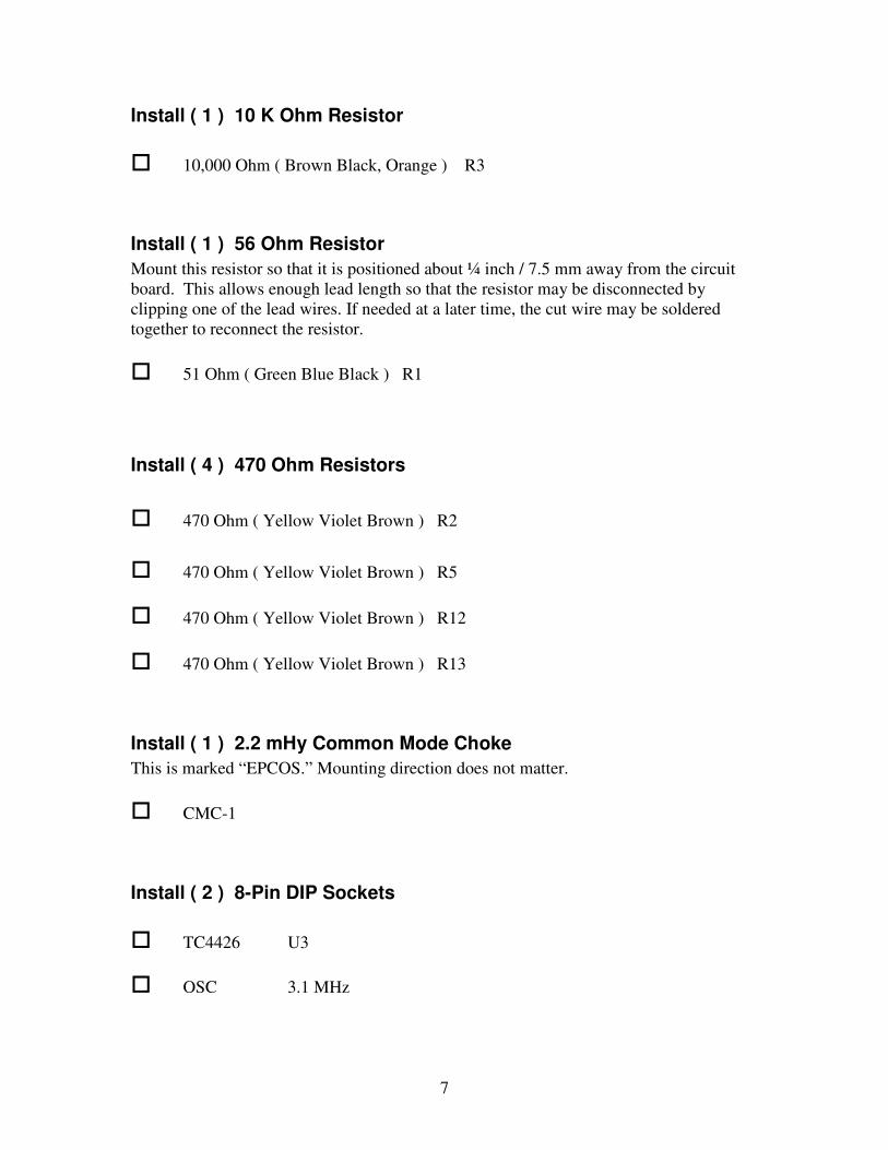
Install ( 1 ) 10 K Ohm Resistor
� 10,000 Ohm ( Brown Black, Orange ) R3
Install ( 1 ) 56 Ohm Resistor
Mount this resistor so that it is positioned about ¼ inch / 7.5 mm away from the circuit
board. This allows enough lead length so that the resistor may be disconnected by
clipping one of the lead wires. If needed at a later time, the cut wire may be soldered
together to reconnect the resistor.
� 51 Ohm ( Green Blue Black ) R1
Install ( 4 ) 470 Ohm Resistors
� 470 Ohm ( Yellow Violet Brown ) R2
� 470 Ohm ( Yellow Violet Brown ) R5
� 470 Ohm ( Yellow Violet Brown ) R12
� 470 Ohm ( Yellow Violet Brown ) R13
Install ( 1 ) 2.2 mHy Common Mode Choke
This is marked “EPCOS.” Mounting direction does not matter.
� CMC-1
Install ( 2 ) 8-Pin DIP Sockets
� TC4426 U3
� OSC 3.1 MHz
8
Install ( 1 ) 14-Pin DIP Socket
� 74HCT14 U5
Install ( 1 ) MC78L05 Voltage Regulator
� 78L05 U2
NOTE – Be sure to install the MC78L05 so that the flat side of the device is facing
towards the mounting position of the large 220 uF 200V electrolytic capacitor that is
marked “220” on the circuit board.
Install ( 1 ) 3-Pin Miniature Green Terminal Block
When installing the terminal block, be sure to install it so that the holes for the
connecting wires are facing towards the edge of the circuit board.
� IRF730
Install ( 1 ) 4-Pin White plastic connector for cooling fan
� FAN
LARGE TERMINAL BLOCK INSTALLATION
When installing the terminal blocks, be sure to install them so that the holes for the
connecting wires are facing towards the edge of the circuit board.
Depending on manufacturing tolerances, the terminal blocks may be a tight press fit into
the circuit board. Be sure to seat the terminal block completely against the circuit board
before soldering. Double check to make sure the wire holes in the terminal blocks are
facing the outer edge of the circuit board before soldering the terminal blocks in place.
To make soldering the terminal boards onto the circuit board an easier task, insert the
terminal blocks onto the circuit board and hold them in position with your hand. Now,
turn the board upside down and carefully place it down on the surface of your
workbench. The PA3 circuit board should now be laying flat against the back of each of
the terminal blocks. It is now an easy task to solder the terminal blocks into position.
9
Install ( 1 ) 2 Position Terminal Strip at This Location:
� AF IN
Install ( 1 ) 6 Position Terminal Strip at This Location:
� GND / +19, GND / + HV, GND / RF OUT
Install
( 1 ) 3 Position Terminal Strip at This Location:
� STW20NK50Z
Install ( 1 ) 3 Position Terminal Strip at This Location:
Be careful to orient the terminal strip in the correct direction, with the transistor mounting
holes facing the edge of the circuit board. If the terminal strip is installed backwards, it
will be almost impossible to remove without damaging the circuit board.
� IRF730 – NOTE – This is the smaller 3 position terminal strip.
Install Ferrite Core Inductors
The connecting wires of these inductors are already bent to fit into the mounting holes of
the circuit board. Please see the photographs at the back of this assembly manual for
correct orientation of these inductors before soldering them in place.
Install ( 1 ) 4.7 uH Ferrite Core Inductor
� 4.7 L1 ( Yellow Violet gold Silver )
10
Install ( 2 ) 2.2 uH Ferrite Core Inductors
� 2.2 L2 ( Red Red Gold Silver )
� 2.2 L3 ( Red Red Gold Silver )
Install ( 1 ) 1000 pF Disc Capacitors
� 1 nF C7
Install ( 2 ) 2200 pF Disc Capacitors
� 2200 C13
� 2200 C14
Install ( 1 ) 8200 pF Poly Film Capacitor
� 8200 C8
Install ( 1 ) 3900 pF Ceramic Capacitor
� 2200 C10
11
Install ( 4 ) 47 uF 16 V Electrolytic capacitors
� 47 C2
� 47 C3
� 47 C4
� 47 C5
Install ( 4 ) 0.47 uF capacitors
� 0.47 C8
� 0.47 C9
� 0.47 C11
� 0.47 C15
Install ( 1 ) 470 uF 25 V Electrolytic Capacitor
� 470 C1
Install ( 3 ) LED’s
Be sure to match the flat side of each LED to its corresponding flat side of the location
marker on the circuit board.
� IPA-1 (Green)
� IPA-2 (Yellow)
� PA Drive (Red)
12
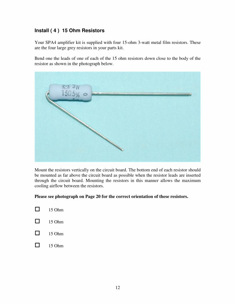
Install ( 4 ) 15 Ohm Resistors
Your SPA4 amplifier kit is supplied with four 15-ohm 3-watt metal film resistors. These
are the four large grey resistors in your parts kit.
Bend one the leads of one of each of the 15 ohm resistors down close to the body of the
resistor as shown in the photograph below.
Mount the resistors vertically on the circuit board. The bottom end of each resistor should
be mounted as far above the circuit board as possible when the resistor leads are inserted
through the circuit board. Mounting the resistors in this manner allows the maximum
cooling airflow between the resistors.
Please see photograph on Page 20 for the correct orientation of these resistors.
� 15 Ohm
� 15 Ohm
� 15 Ohm
� 15 Ohm

13
Install ( 1 ) 220 uF 200 V Electrolytic Capacitor
� 220 C12
Install ( 1 ) L4 Air Core Inductor
� L4
Please see the photographs at the back of this assembly manual for correct orientation of
this inductor before soldering it in place.
The air core inductor L3 in your PA3 kit is supplied with leads that are cut to the proper
length. Make sure that the enamel insulation is removed from the outermost ¼” of each
connecting wire on L3.
If necessary, carefully bend the wires on L3 so that they pass through the mounting holes
in the PA3 circuit board. Be careful not to bend the leads too far so as not to split the
plastic insulation that holds the coil turns together. Insert the leads of L3 through the
holes in the circuit board and carefully solder them in place.
Install the TC4426 Integrated Circuit in its socket.
� 4426 socket (Previously installed.)
Install the 74HCT14 Integrated Circuit in its socket.
� 74HCT14 socket (Previously installed.)
Install the 3.1 MHZ oscillator module in its socket.
� OSC socket (Previously installed.)

14
Installation of the Heat Sink on the IRF740PBF.
To begin installation of the IRF740PBF, the leads of the transistor must be prepared. To
assist you with this procedure, please refer to the photographs shown here.
Locate the components shown in the picture above.
- The large heat sink,
- One 6-30 x 3/8 inch machine screw
- One 6-32 hex nut, the IRF740PBF transistor,
- The MC 7812 voltage regulator.
Locate the point where the leads of the IRF740PBF become slightly narrower. This point
is indicated by the ballpoint pen in the photograph. This is where you will bend the leads
of the IRF740PBF.
15
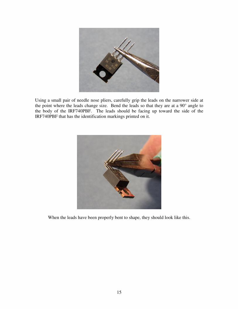
Using a small pair of needle nose pliers, carefully grip the leads on the narrower side at
the point where the leads change size. Bend the leads so that they are at a 90° angle to
the body of the IRF740PBF. The leads should be facing up toward the side of the
IRF740PBF that has the identification markings printed on it.
When the leads have been properly bent to shape, they should look like this.

16
Place the IRF740PBF on a flat surface so that the leads are pointing up. Take the MC
7812 voltage regulator and place it on top of the IRF740PBF, as shown in the photograph
above. You will use the MC 7812 as a cutting guide to trim the leads of the IRF740PBF.
Using a pair of flush cut trimming pliers, cut the leads of the IRF740PBF so that they are
even with the top surface of the MC 7812 voltage regulator. This will leave the leads of
the IRF740PBF at the proper length for inserting in the small three pin terminal block
which was previously soldered to the circuit board.
17
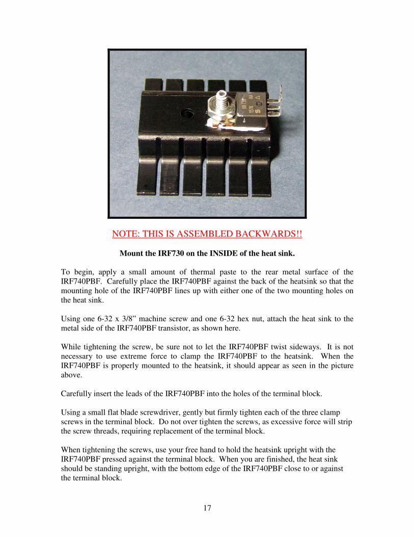
NOTE: THIS IS ASSEMBLED BACKWARDS!!
Mount the IRF730 on the INSIDE of the heat sink.
To begin, apply a small amount of thermal paste to the rear metal surface of the
IRF740PBF. Carefully place the IRF740PBF against the back of the heatsink so that the
mounting hole of the IRF740PBF lines up with either one of the two mounting holes on
the heat sink.
Using one 6-32 x 3/8” machine screw and one 6-32 hex nut, attach the heat sink to the
metal side of the IRF740PBF transistor, as shown here.
While tightening the screw, be sure not to let the IRF740PBF twist sideways. It is not
necessary to use extreme force to clamp the IRF740PBF to the heatsink. When the
IRF740PBF is properly mounted to the heatsink, it should appear as seen in the picture
above.
Carefully insert the leads of the IRF740PBF into the holes of the terminal block.
Using a small flat blade screwdriver, gently but firmly tighten each of the three clamp
screws in the terminal block. Do not over tighten the screws, as excessive force will strip
the screw threads, requiring replacement of the terminal block.
When tightening the screws, use your free hand to hold the heatsink upright with the
IRF740PBF pressed against the terminal block. When you are finished, the heat sink
should be standing upright, with the bottom edge of the IRF740PBF close to or against
the terminal block.
18
Install ( 1 ) MC7812 Voltage Regulator
� 7812 U1
NOTE – Be sure to install the MC7812 so that the exposed metal side of the device is
facing away from the circuit board.
Install the TO220 Mini Heat Sink on the +12 volt regulator
NOTE: It is advisable to apply a small amount of heat sink compound (“thermal grease”)
to the heat sink before attaching the heat sink to the transistor or voltage regulator.
� Install on the MC7812 Voltage Regulator U2 Install SMALL heat sink here.
Install ( 1 ) STW20NK50Z Transistor
Using the 3-connector terminal block for mounting the STW20NK50Z, simply insert the
pins of the STW20NK50Z as far as they will go into the holes of the terminal block and
gently but firmly tighten the clamping screws of the terminal block.
Note that when you mount the PA3 circuit board in its final location, it may be necessary
to bend the pins of the STW20NK50Z in order to obtain the proper clearance of the PA3
circuit board from the heat sink.
When installing the transistor on the heat sink, be sure to use the supplied Bergquist
thermal pad (white in color) or a good quality, high thermal transfer insulating sheet
between the transistor and the heat sink.
The heat sink used should be able to dissipate a heat load of 100 watts or more.
The part of the heat sink where the MOSFET is mounted must be at least 3/8 inch / 9.25
mm thick. This is necessary so that it will be able to spread out the heat from the
MOSFET. Using a heat sink with less thickness risks damage to the MOSFET due to
overheating at high power levels,
� STW20NK50Z

19
FINAL INSPECTION
Using a magnifying glass and a bright light, carefully inspect the top and bottom of the
finished circuit board for any unwanted solder splashes between connections, short wire
clippings, or anything else that may cause problems during operation of the PA3.
Should you wish to remove the solder flux residue from the finished circuit board, you
may use a commercial flux remover or 100% Isopropyl alcohol. Use only 100%
Isopropyl alcohol. Rubbing alcohol is NOT suitable for removing the flux residue due to
its high water content and the denaturing ingredients contained in rubbing alcohol. After
cleaning the board, allow it to dry thoroughly before continuing.
This completes the assembly of the PA3 circuit board.
PA3 CIRCUIT BOARD CHECKOUT PROCEDURE
RESISTANCE CHECK
The following resistance checks are to be taken with no external connections to the
circuit board.
Using an Ohmmeter, measure the resistance between the + 19 and GND terminals and
between the + HV and GND terminals. The resistance readings should be greater than
one Megohm. The resistance reading may be low at first when the Ohmmeter leads are
connected, but the resistance reading will increase as the filter capacitors charge up from
the Ohmmeter voltage. After the resistance reading stabilizes, reverse the Ohmmeter
leads and make sure the resistance in the reverse direction also reads greater than one
Megohm.
Your PA3 amplifier is now ready for use. Please consult the PA3 Instruction
Manual for final setup and operating instructions.

20
PA3 v3.0 E Component orientation.
21
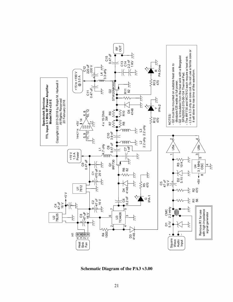
Schematic Diagram of the PA3 v3.00

22
Edited by CAT