assembly and operating manual meg 64 ec
TRANSCRIPT

Translation of original operating manual
Assembly and Operating ManualMEG 64 ECElectrical parallel gripper

Imprint
203.00 | MEG 64 EC | Assembly and Operating Manual | en | 389203
ImprintCopyright:This manual is protected by copyright. The author is SCHUNK GmbH & Co. KG. All rightsreserved. Any reproduction, processing, distribution (making available to third parties),translation or other usage - even excerpts - of the manual is especially prohibited andrequires our written approval.
Technical changes:We reserve the right to make alterations for the purpose of technical improvement.
Document number: 389203
Version: 03.00 | 05/02/2020 | en
© SCHUNK GmbH & Co. KGAll rights reserved.
Dear Customer,thank you for trusting our products and our family-owned company, the leadingtechnology supplier of robots and production machines.Our team is always available to answer any questions on this product and other solutions.Ask us questions and challenge us. We will find a solution!Best regards,Your SCHUNK team
SCHUNK GmbH & Co. KGSpann- und GreiftechnikBahnhofstr. 106 – 134D-74348 Lauffen/NeckarTel. +49-7133-103-0Fax [email protected]

Table of Contents
03.00 | MEG 64 EC | Assembly and Operating Manual | en | 389203
3
Table of Contents1 General.................................................................................................................... 5
1.1 About this manual ................................................................................................ 51.1.1 Presentation of Warning Labels ............................................................... 51.1.2 Applicable documents .............................................................................. 6
1.2 Warranty .............................................................................................................. 61.3 Accessories ........................................................................................................... 61.4 Scope of delivery .................................................................................................. 6
1.4.1 Scope of delivery Gripper ......................................................................... 61.4.2 Scope of delivery Controller ..................................................................... 6
2 Basic safety notes ................................................................................................... 72.1 Intended use......................................................................................................... 72.2 Not intended use.................................................................................................. 72.3 Constructional changes ........................................................................................ 72.4 Spare parts ........................................................................................................... 72.5 Gripper fingers ..................................................................................................... 82.6 Ambient conditions and operating conditions ..................................................... 82.7 Personnel qualification......................................................................................... 92.8 Personal protective equipment.......................................................................... 102.9 Notes on safe operation ..................................................................................... 102.10 Transport ............................................................................................................ 102.11 Malfunctions....................................................................................................... 112.12 Disposal .............................................................................................................. 112.13 Fundamental dangers......................................................................................... 11
2.13.1 Protection during handling and assembly .............................................. 112.13.2 Protection during commissioning and operation ................................... 122.13.3 Protection against dangerous movements............................................. 122.13.4 Protection against electric shock............................................................ 13
2.14 Notes on particular risks..................................................................................... 14
3 Technical data......................................................................................................... 163.1 Gripper MEG 64 EC............................................................................................. 163.2 Controller MEG C................................................................................................ 17
4 Assembly ................................................................................................................ 184.1 Mechanical connection ...................................................................................... 18
4.1.1 Gripper.................................................................................................... 184.1.2 Controller................................................................................................ 20
4.2 Electrical connection .......................................................................................... 214.2.1 Gripper connector assignment ............................................................... 214.2.2 Terminal assignment MEG C 64.............................................................. 224.2.3 Connecting ground cable........................................................................ 23

Table of Contents
403.00 | MEG 64 EC | Assembly and Operating Manual | en | 389203
5 Start-up .................................................................................................................. 245.1 Notes on start-up ............................................................................................... 245.2 MEG 64 EC and MEG C 64 connection description............................................. 245.3 Performing a reference run................................................................................ 275.4 Position mode..................................................................................................... 285.5 Live mode ........................................................................................................... 315.6 External reset ..................................................................................................... 335.7 Analog set values................................................................................................ 34
5.7.1 Gripping speed - specification ................................................................ 355.7.2 Step - specification ................................................................................. 375.7.3 Gripping force - specification.................................................................. 38
5.8 Example of a possible gripping cycle .................................................................. 395.9 Table of functions ............................................................................................... 41
6 Troubleshooting ..................................................................................................... 436.1 Status LED flashing ............................................................................................. 436.2 Product does not execute a complete stroke..................................................... 446.3 The gripping force drops .................................................................................... 446.4 Product opens or closes jerkily........................................................................... 44
7 Maintenance .......................................................................................................... 457.1 Maintenance intervals........................................................................................ 457.2 Lubricate gripper ................................................................................................ 467.3 Disassembly and assembling .............................................................................. 46
8 Translation of original declaration of incorporation ................................................ 47
9 Annex to Declaration of Incorporation.................................................................... 48

General
03.00 | MEG 64 EC | Assembly and Operating Manual | en | 389203
5
1 General1.1 About this manual
This manual contains important information for a safe andappropriate use of the product.This manual is an integral part of the product and must be keptaccessible for the personnel at all times.Before starting work, the personnel must have read andunderstood this operating manual. Prerequisite for safe working isthe observance of all safety instructions in this manual.Illustrations in this manual are provided for basic understandingand may differ from the actual product design.In addition to these instructions, the documents listed underApplicable documents [} 6] are applicable.
1.1.1 Presentation of Warning Labels
To make risks clear, the following signal words and symbols areused for safety notes.
DANGERDanger for persons!Non-observance will inevitably cause irreversible injury or death.
WARNINGDangers for persons!Non-observance can lead to irreversible injury and even death.
CAUTIONDangers for persons!Non-observance can cause minor injuries.
CAUTIONMaterial damage!Information about avoiding material damage.

General
603.00 | MEG 64 EC | Assembly and Operating Manual | en | 389203
1.1.2 Applicable documents
• General terms of business *• Catalog data sheet of the purchased product *• Assembly and operating manuals of the accessories *The documents marked with an asterisk (*) can be downloaded onour homepage schunk.com
1.2 WarrantyIf the product is used as intended, the warranty is valid for 24months from the ex-works delivery date under the followingconditions:• Observe the specified maintenance and lubrication intervals• Observe the ambient conditions and operating conditionsParts touching the workpiece and wear parts are not included inthe warranty.
1.3 AccessoriesA wide range of accessories are available for this productFor information regarding which accessory articles can be usedwith the corresponding product variants, see catalog data sheet.
1.4 Scope of delivery
1.4.1 Scope of delivery Gripper
The scope of delivery includes• Electrical parallel gripper MEG 64 EC in the ordered model• Accessory pack
1.4.2 Scope of delivery Controller
The scope of delivery includes• Controller MEG C in the version ordered

Basic safety notes
03.00 | MEG 64 EC | Assembly and Operating Manual | en | 389203
7
2 Basic safety notes2.1 Intended use
The product is designed exclusively for gripping and temporarilyholding workpieces or objects.• The product may only be used within the scope of its technical
data, Technical data [} 16].• When implementing and operating components in safety-
related parts of the control systems, the basic safety principlesin accordance with DIN EN ISO 13849-2 apply. The proven safetyprinciples in accordance with DIN EN ISO 13849-2 also apply tocategories 1, 2, 3 and 4.
• The product is intended for installation in a machine/system.The applicable guidelines must be observed and complied with.
• The product is intended for industrial and industry-oriented use.• Appropriate use of the product includes compliance with all
instructions in this manual.
2.2 Not intended useIt is not intended use if the product is used, for example, as apressing tool, stamping tool, lifting gear, guide for tools, cuttingtool, clamping device or a drilling tool.• Any utilization that exceeds or differs from the appropriate use
is regarded as misuse.
2.3 Constructional changesImplementation of structural changesBy conversions, changes, and reworking, e.g. additional threads,holes, or safety devices can impair the functioning or safety of theproduct or damage it.• Structural changes should only be made with the written
approval of SCHUNK.
2.4 Spare partsUse of unauthorized spare partsUsing unauthorized spare parts can endanger personnel anddamage the product or cause it to malfunction.• Use only original spare parts or spares authorized by SCHUNK.

Basic safety notes
803.00 | MEG 64 EC | Assembly and Operating Manual | en | 389203
2.5 Gripper fingersRequirements for the gripper fingersStored energy within the product creates the risk of seriousinjuries and significant property damage.• Arrange the gripper fingers in a way that the product reaches
either the position "open" or "closed" in a de-energized state.• Only exchange the gripper fingers when no residual energy
remains in the product.• Make sure that the product and the top jaws are a sufficient
size for the application.
2.6 Ambient conditions and operating conditionsRequired ambient conditions and operating conditionsIncorrect ambient and operating conditions can make the productunsafe, leading to the risk of serious injuries, considerable materialdamage and/or a significant reduction to the product's life span.• Make sure that the product is used only in the context of its
defined application parameters, Technical data [} 16].• Make sure that the product is a sufficient size for the
application.• Make sure that the environment is free from splash water and
vapors as well as from abrasion or processing dust. Exceptionsare products that are designed especially for contaminatedenvironments.

Basic safety notes
03.00 | MEG 64 EC | Assembly and Operating Manual | en | 389203
9
2.7 Personnel qualificationInadequate qualifications of the personnelIf the personnel working with the product is not sufficientlyqualified, the result may be serious injuries and significantproperty damage.• All work may only be performed by qualified personnel.• Before working with the product, the personnel must have read
and understood the complete assembly and operating manual.• Observe the national safety regulations and rules and general
safety instructions.
The following personal qualifications are necessary for the variousactivities related to the product:
Trained electrician Due to their technical training, knowledge and experience, trainedelectricians are able to work on electrical systems, recognize andavoid possible dangers and know the relevant standards andregulations.
Qualified personnel Due to its technical training, knowledge and experience, qualifiedpersonnel is able to perform the delegated tasks, recognize andavoid possible dangers and knows the relevant standards andregulations.
Instructed person Instructed persons were instructed by the operator about thedelegated tasks and possible dangers due to improper behaviour.
Service personnel ofthe manufacturer
Due to its technical training, knowledge and experience, servicepersonnel of the manufacturer is able to perform the delegatedtasks and to recognize and avoid possible dangers.

Basic safety notes
1003.00 | MEG 64 EC | Assembly and Operating Manual | en | 389203
2.8 Personal protective equipmentUse of personal protective equipmentPersonal protective equipment serves to protect staff againstdanger which may interfere with their health or safety at work.• When working on and with the product, observe the
occupational health and safety regulations and wear therequired personal protective equipment.
• Observe the valid safety and accident prevention regulations.• Wear protective gloves to guard against sharp edges and
corners or rough surfaces.• Wear heat-resistant protective gloves when handling hot surfaces.• Wear protective gloves and safety goggles when handling
hazardous substances.• Wear close-fitting protective clothing and also wear long hair in
a hairnet when dealing with moving components.
2.9 Notes on safe operationIncorrect handling of the personnelIncorrect handling and assembly may impair the product's safetyand cause serious injuries and considerable material damage.• Avoid any manner of working that may interfere with the
function and operational safety of the product.• Use the product as intended.• Observe the safety notes and assembly instructions.• Do not expose the product to any corrosive media. This does not
apply to products that are designed for special environments.• Eliminate any malfunction immediately.• Observe the care and maintenance instructions.• Observe the current safety, accident prevention and
environmental protection regulations regarding the product'sapplication field.
2.10 TransportHandling during transportIncorrect handling during transport may impair the product'ssafety and cause serious injuries and considerable materialdamage.• When handling heavy weights, use lifting equipment to lift the
product and transport it by appropriate means.• Secure the product against falling during transportation and
handling.• Stand clear of suspended loads.

Basic safety notes
03.00 | MEG 64 EC | Assembly and Operating Manual | en | 389203
11
2.11 MalfunctionsBehavior in case of malfunctions• Immediately remove the product from operation and report the
malfunction to the responsible departments/persons.• Order appropriately trained personnel to rectify the
malfunction.• Do not recommission the product until the malfunction has
been rectified.• Test the product after a malfunction to establish whether it still
functions properly and no increased risks have arisen.
2.12 DisposalHandling of disposalThe incorrect handling of disposal may impair the product's safetyand cause serious injuries as well as considerable material andenvironmental harm.• Follow local regulations on dispatching product components for
recycling or proper disposal.
2.13 Fundamental dangersGeneral• Observe safety distances.• Never deactivate safety devices.• Before commissioning the product, take appropriate protective
measures to secure the danger zone.• Disconnect power sources before installation, modification,
maintenance, or calibration. Ensure that no residual energyremains in the system.
• If the energy supply is connected, do not move any parts byhand.
• Do not reach into the open mechanism or movement area ofthe product during operation.
2.13.1 Protection during handling and assembly
Incorrect handling and assemblyIncorrect handling and assembly may impair the product's safetyand cause serious injuries and considerable material damage.• Have all work carried out by appropriately qualified personnel.• For all work, secure the product against accidental operation.• Observe the relevant accident prevention rules.• Use suitable assembly and transport equipment and take
precautions to prevent jamming and crushing.

Basic safety notes
1203.00 | MEG 64 EC | Assembly and Operating Manual | en | 389203
Incorrect lifting of loadsFalling loads may cause serious injuries and even death.• Stand clear of suspended loads and do not step into their
swiveling range.• Never move loads without supervision.• Do not leave suspended loads unattended.
2.13.2 Protection during commissioning and operation
Falling or violently ejected componentsFalling and violently ejected components can cause serious injuriesand even death.• Take appropriate protective measures to secure the danger
zone.• Never step into the danger zone during operation.
2.13.3 Protection against dangerous movements
Unexpected movementsResidual energy in the system may cause serious injuries whileworking with the product.• Switch off the energy supply, ensure that no residual energy
remains and secure against inadvertent reactivation.• The faulty actuation of conected drives may cause dangerous
movements.• Operating mistakes, faulty parameterization during
commissioning or software errors may trigger dangerousmovements.
• Never rely solely on the response of the monitoring function toavert danger. Until the installed monitors become effective, itmust be assumed that the drive movement is faulty, with itsaction being dependent on the control unit and the currentoperating condition of the drive. Perform maintenance work,modifications, and attachments outside the danger zonedefined by the movement range.
• To avoid accidents and/or material damage, human access tothe movement range of the machine must be restricted. Limit/prevent accidental access for people in this area due throughtechnical safety measures. The protective cover and protectivefence must be rigid enough to withstand the maximum possiblemovement energy. EMERGENCY STOP switches must be easilyand quickly accessible. Before starting up the machine orautomated system, check that the EMERGENCY STOP system isworking. Prevent operation of the machine if this protectiveequipment does not function correctly.

Basic safety notes
03.00 | MEG 64 EC | Assembly and Operating Manual | en | 389203
13
2.13.4 Protection against electric shock
Work on electrical equipmentTouching live parts may result in death.• Work on the electrical equipment may only be carried out by
qualified electricians in accordance with the electricalengineering regulations.
• Lay electrical cables properly, e. g. in a cable duct or a cablebridge. Observe standards.
• Before connecting or disconnecting electrical cables, switch offthe power supply and check that the cables are free of voltage.Secure the power supply against being switched on again.
• Before switching on the product, check that the protectiveearth conductor is correctly attached to all electricalcomponents according to the wiring diagram.
• Check whether covers and protective devices are fitted toprevent contact with live components.
• Do not touch the product's terminals when the power supply isswitched on.
Possible electrostatic energyComponents or assembly groups may become electrostaticallycharged. When the electrostatic charge is touched, the dischargemay trigger a shock reaction leading to injuries.• The operator must ensure that all components and assembly
groups are included in the local potential equalisation inaccordance with the applicable regulations.
• While paying attention to the actual conditions of the workingenvironment, the potential equalisation must be implementedby a specialist electrician according to the applicableregulations.
• The effectiveness of the potential equalisation must be verifiedby executing regular safety measurements.

Basic safety notes
1403.00 | MEG 64 EC | Assembly and Operating Manual | en | 389203
2.14 Notes on particular risks
DANGERDanger from electric voltage!Touching live parts may result in death.• Switch off the power supply before any assembly, adjustment
or maintenance work and secure against being switched onagain.
• Only qualified electricians may perform electrical installations.• Check if de-energized, ground it and hot-wire.• Cover live parts.
DANGERRisk of fatal injury from suspended loads!Falling loads can cause serious injuries and even death.• Stand clear of suspended loads and do not step within their
swiveling range.• Never move loads without supervision.• Do not leave suspended loads unattended.• Wear suitable protective equipment.
WARNINGRisk of injury from objects falling and being ejected!Falling and ejected objects during operation can lead to seriousinjury or death.• Take appropriate protective measures to secure the danger
zone.
WARNINGRisk of injury due to unexpected movements!If the power supply is switched on or residual energy remains inthe system, components can move unexpectedly and causeserious injuries.• Before starting any work on the product: Switch off the power
supply and secure against restarting.• Make sure, that no residual energy remains in the system.

Basic safety notes
03.00 | MEG 64 EC | Assembly and Operating Manual | en | 389203
15
WARNINGRisk of injury from crushing and impacts!Serious injury could occur during the base jaw procedure andwhen breaking or loosening the gripper fingers.• Wear suitable protective equipment.• Do not reach into the open mechanism or the movement area
of the product.
WARNINGRisk of injury from sharp edges and corners!Sharp edges and corners can cause cuts.• Use suitable protective equipment.
WARNINGRisk of burns through contact with hot surfaces!Surfaces of components can heat up severely during operation.Skin contact with hot surfaces causes severe burns to the skin.• For all work in the vicinity of hot surfaces, wear safety gloves.• Before carrying out any work, make sure that all surfaces have
cooled down to the ambient temperature.
WARNINGRisk of injury from objects falling in the event of an energysupply failureIn case of an energy supply failure, the gripping force decreasesand a secure hold on the gripped workpiece cannot beguaranteed.• Take suitable protective measures to secure the danger zone.

Technical data
1603.00 | MEG 64 EC | Assembly and Operating Manual | en | 389203
3 Technical data3.1 Gripper MEG 64 EC
Stroke per finger [mm] 10Gripping force [N] * 40 – 140Workpiece weight [kg](Recommendation) [kg] **
0.85
Power supply [VDC] (nominal range) Supply via MEG C 64Current input Input via MEG C 64Max. speed (gripping) [mm/s] 17Weight [kg] 1.42Max. permissible finger length [mm] 64Min. ambient temperature [°C]Max. ambient temperature [°C]
+5+55
Repeatability [mm] *** 0.02IP rating 30Noise emission [dB(A)] ≤ 70
* Gripping force is the arithmetical sum of the individualforces acting on the gripper jaws at a distance of P=25 mm.
** Values for friction coefficient µ = 0.1 and safety factor v = 2.The values can be increased in the case of form-fitting.
*** Distribution of the mechanical end positions after 100consecutive strokes.
A controller is needed to operate the gripper. For this purpose,SCHUNK offers the MEG C 64 (ID number 307006).More technical data is included in the catalog data sheet.Whichever is the latest version.

Technical data
03.00 | MEG 64 EC | Assembly and Operating Manual | en | 389203
17
3.2 Controller MEG CPower supply [VDC] 24Max. Current input [A] 1.5Weight [kg] 0.3IP rating 30Nominal temperature range [°C] -10 to 65Setting options • Force setting
• Closing and opening times(speed)
• Stroke adjustmentInterface Digital / Analog I/Os

Assembly
1803.00 | MEG 64 EC | Assembly and Operating Manual | en | 389203
4 Assembly4.1 Mechanical connection
4.1.1 Gripper
Connection dimensions MEG 64 EC
1 for bore hole ∅10± 0.1 for M6 thread
3 for bore hole ∅10± 0.1 for M6 thread
2 Centering sleeve ∅10 (2x) 4 Centering ∅10 (4x)
The gripper is mounted to the base or side via M6 threads. Thecentering is performed via the centering sleeves contained in theaccessory kit.

Assembly
03.00 | MEG 64 EC | Assembly and Operating Manual | en | 389203
19
Dimensions MEG 64 EC (5xD bending radius applies to Schunk connection cables)
I OPEN II CLOSED1 5xD bending radius

Assembly
2003.00 | MEG 64 EC | Assembly and Operating Manual | en | 389203
4.1.2 Controller
The MEG C controller is mounted to a mounting rail as per EN50022 via the metal foot locking device.
Mounting MEG C 64
1 Terminals for PLC 3 Assembly on mounting railas per EN 50022
2 Terminals for MEG-EC assembly on mounting rail as per EN50022
Dimensions MEG C 64

Assembly
03.00 | MEG 64 EC | Assembly and Operating Manual | en | 389203
21
4.2 Electrical connection4.2.1 Gripper connector assignment
X2 device plug on the MEG 40 EC
Device plug pin assignment X2
Pin Function1 Connection 1 motor2 Connection 2 motor3 Connection 3 motor4 Connection 4 motor

Assembly
2203.00 | MEG 64 EC | Assembly and Operating Manual | en | 389203
4.2.2 Terminal assignment MEG C 64
Terminal Function Miscellaneous Cable color1 Connection 3 motor Connection for MEG 64 EC Blue2 Shield (gripper connecting cable PE) Connection for MEG 64 EC3 Connection 4 motor Connection for MEG 64 EC Black456 GND for position output GND analog output7 Connection 1 motor Connection for MEG 64 EC Brown89 Connection 2motor Connection for MEG 64 EC White10 Supply (+24 V) 24 VDC ± 2%11 External reset Digital input12 Supply (GND) GND13 Gripper stopped Digital output14 Reference run carried out Digital output15 Analog position output (0-5V) Analog output16 24V PLC 24 VDC ± 10%17 GND PLC GND, potential of PCL18 Target position reached Digital output19 Reference run Digital input20 Gripper closed Digital input21 Gripper open Digital input22 Analog input: Speed 0V-10V (to the GND PLC)23 Analog input: Steps 0V-10V (to the GND PLC)24 Analog input: Force 0V-10V (to the GND PLC)

Assembly
03.00 | MEG 64 EC | Assembly and Operating Manual | en | 389203
23
4.2.3 Connecting ground cable
Ground connection
1 Screw * 4 Toothed lock washer2 Washer 5 Product3 Cable lug 6 Ground marking
*) Tightening torque: 5 NmA ground connection with a sufficient cross-section must beestablished between the product and the machine on thecustomer's premises. The ground cable must be mounted on the threaded holeidentified by the ground marking.
NOTEOnly connect the ground cable at the location intended for thispurpose.Always mount the ground cable singly.
Always use all components to screw in the ground cable and installthem in this order: toothed lock washer, cable lug, washer andbolt. See "Ground connection" diagram. Observe the tighteningtorque.
Start-up
2403.00 | MEG 64 EC | Assembly and Operating Manual | en | 389203
5 Start-up5.1 Notes on start-up
The control cable must be de-energized when connecting to thegripper.The workpiece to be gripped should then be gripped in "livemovement" mode.The current at the input "Analog input: steps" (terminal 23) mustcorrespond to the distance from the current position to theposition which you wish to use for pre-positioning. Resulting froma rising edge on the inputs "Gripper open" or "Gripper closed", thegripper moves inwards or outwards by the distance set.Monitoring of the output "Target pos. reached".Prepositioning reached - output issues high signal.The gripper is prepositioned in "positioning movement" mode,then the workpiece is gripped in live movement. The gripper canbe prepositioned accordingly and the gripping cycle can startanew.
5.2 MEG 64 EC and MEG C 64 connection descriptionThe MEG 64 EC does one stroke of 10 mm per jaw.Stroke, force and speed can be set on the external MEG Ccontroller via analog inputs or potentiometers. Gripperfunctionalities such as opening, closing and reference run arespecified via decoupled digital inputs on the MEG C controller.Status signals of the MEG C external controller are sent back to thesuperordinate control (e.g. PLC) via digital outputs. The currentposition is issued as analog value.

Start-up
03.00 | MEG 64 EC | Assembly and Operating Manual | en | 389203
25
MEG C
1 "Status" LED 3 Speed (P2)2 Position (P3) 4 Force (P1)
The MEG C external controller for actuating the MEG EC gripperhas three potentiometers:• P1: Adjusting the gripping force• P2: Adjusting the gripping speed• P3: Adjusting the traverse path / the position (incremental input
of the relative value)Each potentiometer is assigned a measuring jack, on which thevoltage set can be tapped for measuring.The "Status" LED provides information about possible operatingstatuses of the controller and about problems in the event of amalfunction. The possible causes for malfunctions that can bedisplayed by the Status LED are listed in the chapter on ProblemAnalysis.The MEG C controller (terminals 1, 3, 7, 9) is connected via a 4-pincontrol cable on the X2 device plug of the MEG EC gripper. Weoffer prefabricated control cables for this purpose (☞ accessoriesin the catalog).

Start-up
2603.00 | MEG 64 EC | Assembly and Operating Manual | en | 389203
For the allocation of further inputs and outputs / voltage supplies,see the terminal configuration Terminal assignment MEG C 64 [} 22]To operate the MEG C 40 with the MEG 40 EC, at least thefollowing terminals need to be connected:• Supply voltage (terminals 10 and 12)• Supply voltage of the digital I/Os (terminals 16 and 17)• Connection of the MEG 40 EC gripper (terminals 1, 3, 7, 9)• Digital inputs "Gripper open" (terminal 21) and "Gripper
closed" (terminal 20)The other inputs and outputs must be assigned in accordance withthe application or relevant case. After connecting the supply voltage,the Status LED flashes six times and then lights up continuously. TheMEG C controller is then ready for operation. If the Status LED flashesconstantly after switching on the MEG C, this indicates a malfunctionand you will need to perform a fault analysisA new command is always carried out with a rising edge on thedigital inputs. This command in turn is completed with a fallingedge. During command execution it must be ensured that theinput signal does not bounce.The gripper opens if a rising edge is identified at the "Gripperopen" input. In the event of a falling edge, the command is ended,and the gripper stops. This works in the same way for the "Gripperclosed" input. It is necessary to end the previous command with afalling edge before a new command is executed. In other words, itis imperative to ensure that the previous command was endedwith a falling edge.

Start-up
03.00 | MEG 64 EC | Assembly and Operating Manual | en | 389203
27
5.3 Performing a reference runThe reference run is only required if the analog output "Analogposition output" (terminal 15) is to be used in the application. Areference run can be performed outward or inward.
ProcedureØ Apply a High signal to the digital input "Reference
run" (terminal 19).Ø In the case of a reference run outward, apply a High edge to the
digital input "Gripper open" (terminal 21).Ø In the case of a reference run inward, apply a High edge to the
digital input "Gripper closed" (terminal 20).Ø Wait until the digital output "Reference run
performed" (terminal 14) has been set to high.Ø After having performed the reference run, set the inputs
"Reference run" and "Gripper open" or "Gripper closed" to Lowsignal.
After performing the reference run, a High signal is issued at thedigital output "Reference run performed" (terminal 14). A Highlevel will be applied at the output until the voltage supply isswitched off or the external reset is actuated or a new referencerun is triggered.

Start-up
2803.00 | MEG 64 EC | Assembly and Operating Manual | en | 389203
5.4 Position modeIn order to attain an economical cycle time in an automationprocess, we recommend prepositioning the claw jaws. This meansthat the gripper is moved to a position that is minimally"larger" (with O.D. grippers) or "smaller" (with I.D. grippers) thanthe workpiece to be gripped. For this purpose, the "positionmode", i.e. step mode is used. The distance the gripper is to coverfrom the current position towards "open" or "closed" is in thismode specified by "Analog input: Position" (terminal 23) or by"Pos." potentiometer (potentiometer P3).This means that the stroke that the gripper performs depends onthe analog voltage value that is present at the input or thepotentiometer. This analog value must be present prior toexecution of the "Gripper open" or "Gripper closed" command.If the gripper moves to an end position or onto a workpiece inposition mode, the current movement command is reset and thegripper stops. The superordinate control unit only receives thedigital signal "Gripper stopped" (terminal 13), but not the "Targetposition reached" signal (terminal 18).MEG 64 EC achieves a relative positioning accuracy of 0.1 mm. Thisis the accuracy with which a stroke specified by the potentiometeror the analog input is moved from the current position, if no steploss occurs due to collision of the claw jaws with a workpiece orthe like.

Start-up
03.00 | MEG 64 EC | Assembly and Operating Manual | en | 389203
29
ProcedureØ Specification of the distance the gripper is to travel at the "Analog
input: Position" (terminal 23) or at the "Pos." potentiometer(potentiometer P3) - (specification applies as of the currentposition).
Ø The analog values for speed ("Analog input: Speed" (terminal 22)or "Speed" potentiometer (potentiometer P2) and force ("Ana-log input: Force) (terminal 24) or "Force" potentiometer (poten-tiometer P1) must also be present prior to command execution(the desired values can be found under "Analog inputs").
Ø With a rising edge on one of the two digital inputs "Gripperopen" (terminal 21) or "Gripper closed" (terminal 20) the newgripping position is approached by the specified value.
Ø During the movement the digital output "Gripperstopped" (terminal 13) becomes low.
Ø The gripper movement can be measured via the output "analogposition output".
Ø After successful performance of a positioning movement, a Highsignal is issued at the "Target-pos. reached" output (terminal 18)and at the digital output "Gripper stopped" (terminal 13).
Successful performance of the positioning movement means that thegripper could perform the stroke travel that was specified by the ana-log value. If the next travel command is specified, a Low signal isagain issued at the output.The output "Analog position output" (terminal 15) issues thecurrent gripper position in the form of an analog value after eachreference run and at any point in time.The following diagram shows in which way the output voltage andthe position of the gripper are connected.
Analog position outputOutput voltage in V
Position in mm
Connection between analog position output (terminal 15) and position of the gripper
Note that the position may drift due to step losses. To counter thisdrift, we recommend performing another reference run before thedeviation is too large for the application.

Start-up
3003.00 | MEG 64 EC | Assembly and Operating Manual | en | 389203
NOTEIf precise measurements are necessary, it is recommendable toadjust the output voltage once (this will not prevent a positionoutput drift).
ProcedureØ Reference gripper "internally" or "externally".Ø Insert gauge blocks with regard to the gripping positions
approached later.Ø Open or close gripper.Ø Measure the output voltage for each gauge block and use it as
the reference voltage for the respective position.During operation of the gripper in the automated system, thesereference voltages can then be compared with the analog outputsignal "Position output" (terminal 15) (e.g. in order to start furtheractions). Depending on the required precision and due to theposition output drift, all x-cycles must be re-referenced (Highsignal on "Reference run [terminal 19] + High edge on "Gripperopen" (terminal 21) or "Gripper closed" (terminal 20). In the caseof high demands on the precision of the output "Analog positionoutput", we recommend performing a reference run before eachgripping cycle.(x must be determined experimentally in the application)

Start-up
03.00 | MEG 64 EC | Assembly and Operating Manual | en | 389203
31
5.5 Live modeIn order to safely grip a workpiece with a reproducible force(within the specifications), we recommend performing thegripping process in one of the two "live movement" modes.Live mode 1 is recommendable if you can rule out that theworkpiece to be gripped may be lost as a result of excessivelydynamic gripper movements (e.g. gripper on a 6-axis robot withvery dynamic swivel movements). In this mode the system-relatedgripping force fluctuations are minimized (e.g. due to torquefluctuations of the stepper motor). Once the gripper jaws arrive ata resistance (workpiece), the gripper is only further provided withcurrent, but no longer actively clocked so as to allow for gentlegripping.Live mode 2 is recommended if the above mentioned condition isnot fulfilled, i.e. to not loose the gripped workpiece when thegripper is attached to a highly dynamic axis and an inelasticworkpiece is to be force-fit gripped. The gripper drive is activelyclocked on during gripping. This means that the claw jaws moveagainst the resistance generated by the workpiece. This preventsworkpiece loss. With this method, system-related gripping forcefluctuations of +/-15% of the maximum force may occur.

Start-up
3203.00 | MEG 64 EC | Assembly and Operating Manual | en | 389203
Procedure for live mode 1Ø The voltage at the input "Analog steps" (terminal 23) and at the
"Pos." potentiometer (potentiometer P3) must be set to 0V.Ø The analog values for speed ("Analog input: Speed" (terminal
22) or "Speed" potentiometer (potentiometer P2) and force("Analog input: Force) (terminal 24) or "Force" potentiometer(potentiometer P1) must be set to the application-specific value(the desired values can be found under "Analog inputs").
Ø Due to a rising edge at the digital inputs "Gripperopen" (terminal 21) or "Gripper closed" (terminal 20), thegripper opens or closes based on the preset force. During thegripper finger movement, the digital output "Gripperstopped" (terminal 13) issues a Low signal.
Ø If the gripper moves to the workpiece stop, the output "Gripperstopped" (terminal 13) issues a High signal; the gripper is,however, further supplied with electrical current.
Ø The workpiece is safely gripped until the signal on the input"Gripper open" (terminal 21) or "Gripper closed" (terminal 20) isreset by a falling edge.

Start-up
03.00 | MEG 64 EC | Assembly and Operating Manual | en | 389203
33
Procedure for live mode 2Ø The voltage at the input "Analog steps" (terminal 23) and at the
"Pos." potentiometer (potentiometer P3) must be set to 0V.Ø The analog values for speed ("Analog input: Speed" (terminal
22) or "Speed" potentiometer (potentiometer P2) and force("Analog input: Force) (terminal 24) or "Force" potentiometer(potentiometer P1) must be set to the application-specific value(the desired values can be found under "Analog inputs").
Ø When twice applying a rising edge at the digital inputs "Gripperopen" (terminal 21) or "Gripper closed" (terminal 20), thegripper opens or closes in live mode 2 based on the presetforce. For this the second rising edge must be carried out on thesame terminal ("Gripper open" (terminal 21) or "Gripperclosed" (terminal 20) as the first rising edge. If prior to the livemovement a position movement was performed in the samedirection, only one rising edge is required at the input terminals.During the gripper finger movement, the digital output "Gripperstopped" (terminal 13) issues a Low signal.
Ø If the gripper moves to the workpiece stop, the output "Gripperstopped" (terminal 13) issues a High signal; the gripper is,however, further supplied with electrical current and clocked.
Ø The workpiece is safely gripped until the signal on the input"Gripper open" (terminal 21) or "Gripper closed" (terminal 20) isreset by a falling edge.
NOTEIf a live movement is performed in the same directionimmediately after a travel movement in "position mode", thenyou will immediately be in live mode 2, since a rising edge hasalready been applied in order to perform the position movementand the second rising edge has been applied in the same directionof movement for the live movement. For live mode 1, you mustfirst apply a rising edge at the digital input ("Gripperopen" (terminal 21) or "Gripper closed" (terminal 20) of therespective other movement direction and then immediately resetit again. Then the live movement can be enabled in the actualdirection. You will then be in live mode 1.
5.6 External resetWhen applying a rising and then a falling edge at the input "Reset",a reset is performed in the internal micro-processor. This means thegripper immediately stops and all outputs are reset. The nextcommand that arrives is then performed entirely normally.
The controller takes about 5 seconds to perform a reset.

Start-up
3403.00 | MEG 64 EC | Assembly and Operating Manual | en | 389203
5.7 Analog set valuesThe analog values can either be specified by the PLC or entereddirectly on the gripper control. Setting these values in the grippercontrol is done via the potentiometers that are accessible via thehousing top of the MEG C 40 controller. The analog voltages thatare set via the potentiometers can be measured via thecorresponding measuring jacks.When applying analog voltages (level > 0.2 V) to the correspondinginputs (terminals 22, 23, 24) of the gripper control, the presetpotentiometer values are ignored.If the analog values are to be set via the gripper control(potentiometer), there must not be any voltage on the externalanalog inputs (put inputs onto GND, if possible).If the analog voltages are specified by the PLC, it isrecommendable that the internal analog voltages are set to 0 V onthe potentiometers.You can also combine external (via PLC) and internal (via thepotentiometers) specifications. If, for instance, the positionmovement is to be automated in a process and the force andgripper speed are to remain unchanged, then these two values canbe set at the Electronics using the potentiometers and the valuefor the position is specified separately (PLC).In the event of external voltage specification and due to slightchanges in the voltage values, the set values, steps, force andspeed may change as well. Ensure that the voltage values do notchange to an extent (unintended) that would make damage to theworkpiece possible as a result of the gripping process.

Start-up
03.00 | MEG 64 EC | Assembly and Operating Manual | en | 389203
35
5.7.1 Gripping speed - specification
The diagrams below show the connection between the speed andthe input voltage of the external input "Speed" (terminal 22) orthe "Speed" potentiometer (potentiometer P2).
Power mode: Speed = f[input voltage] via external input
Speedin mm/s
Preset voltage of external input in V
Speed in live mode in relation to external analog input "Speed" (terminal 22)
Power mode: Speed = f[input voltage] at potentiometer
Speedin mm/s
Preset voltage in V
Speed in live mode in relation to input voltage on the "Speed" potentiometer(potentiometer P2)

Start-up
3603.00 | MEG 64 EC | Assembly and Operating Manual | en | 389203
Step mode: Speed = f[input voltage] via external input
Speedin mm/s
Preset voltage of external input in V
Speed in step/position mode in relation to the external analog input "Speed" (terminal22)
Step mode: Speed = f[input voltage] at potentiometer
Speedin mm/s
Preset voltage in V
Speed in step/position mode in relation to input voltage on the "Speed" potentiometer(potentiometer P2)

Start-up
03.00 | MEG 64 EC | Assembly and Operating Manual | en | 389203
37
5.7.2 Step - specification
The distance the gripper is to cover from the current positiontowards "open" or "closed" is in this mode specified by "Analoginput: Position" (terminal 23) or by "Pos." potentiometer(potentiometer P3). This means that the stroke that the gripperperforms depends on the analog voltage value that is present atthe input or the potentiometer. This analog value must be presentprior to execution of the "Gripper open" or "Gripper closed"command.The following diagram shows the relative traverse path when theinput voltage is specified at the analog input "Steps" (terminal 23).The next diagram shows the relative traverse path when thevoltage is specified via the "Pos." potentiometer (potentiometerP3) on the controller MEG C.
Travel inmm
Travel preset = f[input voltage] via external input
Input voltage in V
relative traverse path when analog voltage is specified on (terminal 23)
Step mode: Speed = f[input voltage] at potentiometerTravelin mm
Input voltage in V
relative traverse path when analog voltage is specified via potentiometer "Pos." (P3)

Start-up
3803.00 | MEG 64 EC | Assembly and Operating Manual | en | 389203
5.7.3 Gripping force - specification
For system-related reasons (e.g. friction in the gripper and torquefluctuations), fluctuations of ± 15% are possible when setting theforce. To set the gripping force approximately, it suffices to set thegripping force via the "Force" potentiometer (P1) or the externalinput "Force" (terminal 24).The following two illustrations show the relationship between thegripping force and the input voltage of the external input"Force" (terminal 24) or the "Force" potentiometer(potentiometer P1) for finger length P = 30 mm.
Gripping force preset = f[input voltage] via external input
Force in N
Input voltage in V
Gripping force when the analog voltage is specified on (terminal 24)
Force in N
Input voltage in V
Gripping force preset = f[input voltage] via potentiometer
Gripping force when the analog voltage is specified via potentiometer "Force" (P1)
(* Gripping force is the arithmetical sum of the individual forcesacting on the gripper jaws at a distance of P = 30 mm)

Start-up
03.00 | MEG 64 EC | Assembly and Operating Manual | en | 389203
39
5.8 Example of a possible gripping cycleIn order to attain an economical cycle time in an automationprocess, we recommend first prepositioning the claw jaws andthen gripping in live mode. The following example intends topresent the actuation steps required for such a gripping cycle.First the claw jaws travel to a position that is minimally"larger" (with O.D. grippers) or "smaller" (with I.D. grippers) thanthe workpiece to be gripped. For this purpose, the "positionmode", i.e. step mode is used.The distance the gripper is to cover from the current positiontowards "open" or "closed" is in this mode specified by "Analoginput: Position" (terminal 23) or by potentiometer"Pos." (potentiometer P3). This analog value as well as thespecifications for force and speed must be present beforeexecuting the command "Gripper open" or "Gripper closed" inposition mode. After successful performance of a positioningmovement, a High signal is issued at the "Target-pos. reached"output (terminal 18) and at the digital output "Gripperstopped" (terminal 13). Now the specification for the stroke("Analog input: Position" (terminal 23)) or on the "Pos."potentiometer (potentiometer P3) is set to zero Volt so as toswitch from the position mode to the live mode. The livemovement is started via the "Gripper open" or "Gripper closed"command. The set value for the gripping force can be changedduring live movement. The gripping force then simultaneouslychanges to the set value. During the gripper finger movement, thedigital output "Gripper stopped" (terminal 13) issues a Low signal.If the gripper fingers move to the workpiece stop, the output"Gripper stopped" (terminal 13) issues a High signal; the gripper is,however, further supplied with electrical current. The workpiece issafely gripped until the signal on the input "Gripperopen" (terminal 21) or "Gripper closed" (terminal 20) is reset by afalling edge. If the workpiece is located in its place, the input"Gripper open" (terminal 21) or "Gripper closed (terminal 20) (andwith this live movement) is reset and the gripper is opened againin position movement, due to the specification on the "Analoginput: Position" (terminal 23) or on the "Pos."potentiometer(potentiometer P3).

Start-up
4003.00 | MEG 64 EC | Assembly and Operating Manual | en | 389203
ProcedureØ Specification of the distance the gripper is to travel at the
"Analog input: Position" (terminal 23) or at the "Pos."potentiometer (potentiometer P3) - (specification applies as ofthe current position).
Ø The analog values for speed ("Analog input: Speed" (terminal22) or potentiometer "Speed" (potentiometer P2) and force("Analog input: Force) (terminal 24) or "Force" potentiometer(potentiometer P1) must also be present prior to command exe-cution (the desired values can be found under "Analog inputs").
Ø With a rising edge on one of the two digital inputs "Gripperopen" (terminal 21) or "Gripper closed" (terminal 20) the newgripping position is approached by the specified value.
Ø During the movement the digital output "Gripperstopped" (terminal 13) becomes low.
Ø The gripper movement can be measured via the output "analogposition output".
Ø After successful performance of a positioning movement, a Highsignal is issued at the "Target-pos. reached" output (terminal18) and at the digital output "Gripper stopped" (terminal 13).
Ø The voltage at the input "Analog steps" (terminal 23) and at the"Pos." potentiometer (potentiometer P3) must be set to 0V.
Ø The analog values for speed ("Analog input: Speed" (terminal22) or potentiometer "Speed" (potentiometer P2) and force("Analog input: Force) (terminal 24) or potentiometer"Force" (potentiometer P1) must be set to the application-specific value (the desired values can be found under "Analoginputs").
Ø Due to a rising edge at the digital inputs "Gripperopen" (terminal 21) or "Gripper closed" (terminal 20), thegripper opens or closes based on the set force. During thegripper finger movement, the digital output "Gripperstopped" (terminal 13) issues a Low signal.
Ø If the gripper moves to the workpiece stop, the output "Gripperstopped" (terminal 13) issues a High signal; the gripper is,however, further supplied with electrical current.

Start-up
03.00 | MEG 64 EC | Assembly and Operating Manual | en | 389203
41
5.9 Table of functionsThe functions of the terminals are as described in the followingtable:
MEG C terminal actuation
Terminal
Function Description
11 Reset 0V → no function; 24V → MEG C reset13 Gripper stopped 0V → gripper travels; 24V → standstill14 Reference run carried out 0V → not carried out; 24V → carried out15 Analog position output 0V – 5 V (approximately current position);
(0V inside; 5V outside)18 Target position reached 0V → target position not reached; 24V →
target position reached19 Reference run 0V → standstill; 24V → execute command
(with gripper open or closed)20 Gripper closed 0V → standstill; 24V → execute command21 Gripper open 0V → standstill; 24V → execute command22 Speed preselection 0.2V - 10 V23 Step preselection 0.2V - 10 V24 Force preselection 0.2V - 10 V

Start-up
4203.00 | MEG 64 EC | Assembly and Operating Manual | en | 389203
MEG C table of functions
Input controlfunction ofgripper
Reference run(terminal19)
Gripperopen(terminal21)
Gripperclosed(terminal20)
Analogspeedspecification [V]
Analogstepspecification [V]
Analogforcespecification [V]
Reset(terminal11)
Reference runopen
H L 0* 0* 0* L
Reference runclosed
H L 0* 0* 0* L
Gripper open[number ofsteps]
L L 0V-10V(extern)0V-5V(Poti)
0V-10V(extern)0V-5V(Poti)
0V-10V(extern)0V-5V(Poti)
L
Gripper closed[number ofsteps]
L L 0V-10V(extern)0V-5V(Poti)
0V-10V(extern)0V-5V(Poti)
0V-10V(extern)0V-5V(Poti)
L
Gripper open[live mode]
L L 0V-10V(extern)0V-5V(Poti)
0V**(extern) 0V**(Poti)
0V-10V(extern)0V-5V(Poti)
L
Gripper closed[live mode]
L L 0V-10V(extern)0V-5V(Poti)
0V**(extern) 0V**(Poti)
0V-10V(extern)0V-5V(Poti)
L
Reset L L L 0* 0* 0*
Legend: H = 24 V DCL = GND*= not mandatory **= mandatory
1
0
0
1
24V
0V
0V
24V
Gripper OPEN
Gripper CLOSED
min. break time 80 ms
Minimal rest period between 2 commands

Troubleshooting
03.00 | MEG 64 EC | Assembly and Operating Manual | en | 389203
43
6 Troubleshooting6.1 Status LED flashing
Status LED Possible cause TroubleshootingLED on the controller doesnot flash 6 times brieflywhen switching on
No power supply • Check power supply onthe controller
• Repeated switching offand on of the powersupply
LED on the controller doesnot light up after theprocess of switching on iscomplete
No power supply • Check power supply onthe controller
LED on controller flashescontinuously (approx. onceper sec.)
• Gripper not connected• Cable breakage
• Check connection of thegripper to the controllerand correct if necessary
• Check the coilresistances of the motorcables to each other:approx. 8.2 Ohm
LED on controller flashescontinuously (approx. onceevery 2 sec.)
Excessive temperature onthe controller
• Lower gripping force setvalue
• Provide sufficient coolingfor controller
LED on controller flashescontinuously (approx. onceevery 4 sec.)
Under- or overvoltage • Check power supply onthe controller
LED on controller flashescontinuously (approx. 4times every 1 sec.)
Overcurrent warning • Lower gripping force setvalue
- Spindle / spindle nutdefective (overload)
• The gripper can only berepaired at the factory!
- Fingers are mechanicallyjammed
• Check whether theadapter plate is stepped(only in the case oflateral attachment)

Troubleshooting
4403.00 | MEG 64 EC | Assembly and Operating Manual | en | 389203
6.2 Product does not execute a complete strokePossible cause Corrective actionDirt deposits between basic jaws andguidance.
Disassemble and clean the product.
Mounting surface is not sufficiently flat. Check the evenness of the mounting surface.Component part defective. Send product with a SCHUNK repair order or
dismantle product.
6.3 The gripping force dropsPossible cause Corrective actionToo much grease in the mechanicalmovement space.
Clean and lubricate product. Maintenance [} 45]
6.4 Product opens or closes jerkilyPossible cause Corrective actionToo little grease in the mechanical guidingareas.
Clean and lubricate product.Maintenance [} 45]
Mounting surface is not sufficiently flat. Check the evenness of the mounting surface.Mechanical connection [} 18]
Loading too large. Check permissible weight and length of thegripper fingers.Technical data [} 16]

Maintenance
03.00 | MEG 64 EC | Assembly and Operating Manual | en | 389203
45
7 Maintenance7.1 Maintenance intervals
Interval (millioncycles) Maintenance work
1000 cycles or once per day
Travel an entire stroke.
2 Treat all grease areas with lubricant,Lubricate gripper [} 46]
2 Clean all parts thoroughly, check fordamage and wear
For extreme ambient and application conditions, shortenedmaintenance cycles can ensure the lifespan is maintained.
CAUTIONMaterial damage due to hardening lubricants!Lubricants harden more quickly at temperatures above 60°C,leading to possible product damage.• Reduce the lubricant intervals accordingly.
CAUTIONDamage to property caused by insufficient lubrication!Continuously traveling short strokes when the product isinadequately lubricated risks damaging it by causing it to run dry.• Travel the full stroke every 1000 cycles or at least once daily.
Maintenance
4603.00 | MEG 64 EC | Assembly and Operating Manual | en | 389203
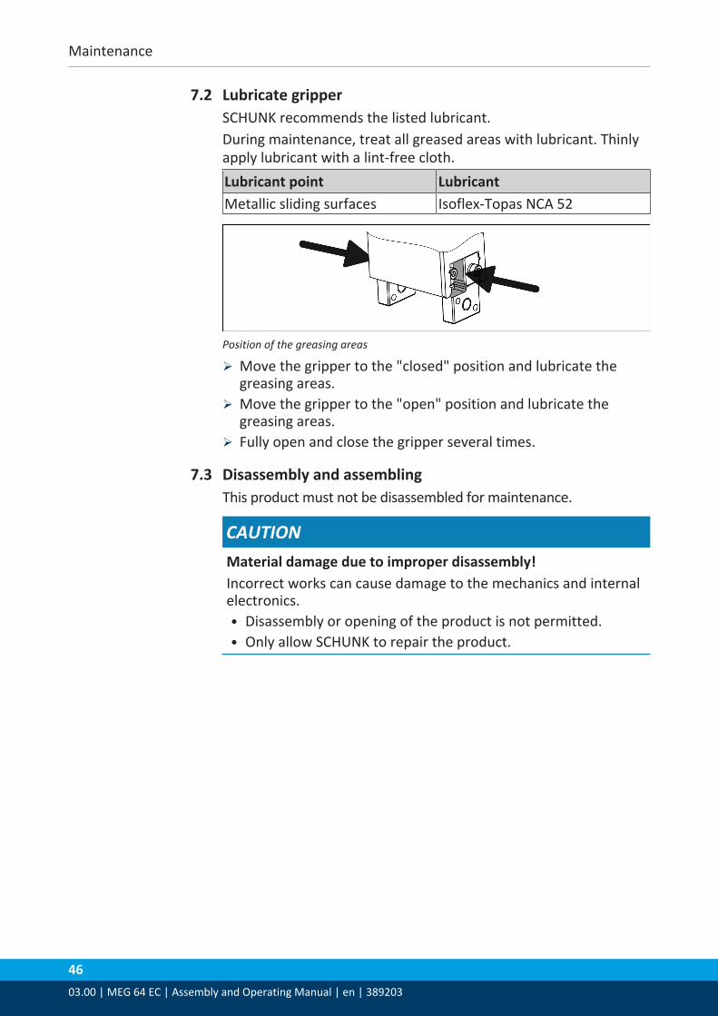
7.2 Lubricate gripperSCHUNK recommends the listed lubricant.During maintenance, treat all greased areas with lubricant. Thinlyapply lubricant with a lint-free cloth.Lubricant point LubricantMetallic sliding surfaces Isoflex-Topas NCA 52
Position of the greasing areas
Ø Move the gripper to the "closed" position and lubricate thegreasing areas.
Ø Move the gripper to the "open" position and lubricate thegreasing areas.
Ø Fully open and close the gripper several times.
7.3 Disassembly and assemblingThis product must not be disassembled for maintenance.
CAUTIONMaterial damage due to improper disassembly!Incorrect works can cause damage to the mechanics and internalelectronics.• Disassembly or opening of the product is not permitted.• Only allow SCHUNK to repair the product.

Translation of original declaration of incorporation
03.00 | MEG 64 EC | Assembly and Operating Manual | en | 389203
47
8 Translation of original declaration of incorporationin terms of the Directive 2006/42/EG, Annex II, Part 1.B of the European Parliament and ofthe Council on machinery.
Manufacturer/Distributor
SCHUNK GmbH & Co. KG Spann- und Greiftechnik Bahnhofstr. 106 – 134 D-74348 Lauffen/Neckar
We hereby declare that on the date of the declaration the following partly completedmachine complied with all basic safety and health regulations found in the directive2006/42/EC of the European Parliament and of the Council on machinery. The declarationis rendered invalid if modifications are made to the product.
Product designation: Electrical parallel gripper/MEG 64 EC / electricand controller MEG 64 EC C
ID number 0306012, 0306006
The partly completed machine may not be put into operation until conformity of themachine into which the partly completed machine is to be installed with the provisions ofthe Machinery Directive (2006/42/EC) is confirmed.
Applied harmonized standards, especially:
EN ISO 12100:2010 Safety of machinery - General principles for design -Risk assessment and risk reduction
The manufacturer agrees to forward on demand the relevant technical documentation forthe partly completed machinery in electronic form to national authorities.The relevant technical documentation according to Annex VII, Part B, belonging to thepartly completed machinery, has been created.
Person authorized to compile the technical documentation: Robert Leuthner, Address: see manufacturer's address
Lauffen/Neckar, January 2020 Dr.-Ing. Manuel Baumeister, Technology &Innovation, Mechatronics & Sensors

Annex to Declaration of Incorporation
4803.00 | MEG 64 EC | Assembly and Operating Manual | en | 389203
9 Annex to Declaration of Incorporationaccording 2006/42/EG, Annex II, No. 1 B
1.Description of the essential health and safety requirements pursuant to 2006/42/EC,Annex I that are applicable and that have been fulfilled with:
Product designation Electrical parallel gripperType designation MEG 64 ECID number 0306012, 0306006
To be provided by the System Integrator for the overall machine ⇓Fulfilled for the scope of the partly completed machine ⇓
Not relevant ⇓
1.1 Essential Requirements1.1.1 Definitions X1.1.2 Principles of safety integration X1.1.3 Materials and products X1.1.4 Lighting X1.1.5 Design of machinery to facilitate its handling X1.1.6 Ergonomics X1.1.7 Operating positions X1.1.8 Seating X
1.2 Control Systems1.2.1 Safety and reliability of control systems X1.2.2 Control devices X1.2.3 Starting X1.2.4 Stopping X1.2.4.1 Normal stop X1.2.4.2 Operational stop X1.2.4.3 Emergency stop X1.2.4.4 Assembly of machinery X1.2.5 Selection of control or operating modes X1.2.6 Failure of the power supply X

Annex to Declaration of Incorporation
03.00 | MEG 64 EC | Assembly and Operating Manual | en | 389203
49
1.3 Protection against mechanical hazards1.3.1 Risk of loss of stability X1.3.2 Risk of break-up during operation X1.3.3 Risks due to falling or ejected objects X1.3.4 Risks due to surfaces, edges or angles X1.3.5 Risks related to combined machinery X1.3.6 Risks related to variations in operating conditions X1.3.7 Risks related to moving parts X1.3.8 Choice of protection against risks arising from moving parts X1.3.8.1 Moving transmission parts X1.3.8.2 Moving parts involved in the process X1.3.9 Risks of uncontrolled movements X
1.4 Required characteristics of guards and protective devices1.4.1 General requirements X1.4.2 Special requirements for guards X1.4.2.1 Fixed guards X1.4.2.2 Interlocking movable guards X1.4.2.3 Adjustable guards restricting access X1.4.3 Special requirements for protective devices X
1.5 Risks due to other hazards1.5.1 Electricity supply X1.5.2 Static electricity X1.5.3 Energy supply other than electricity X1.5.4 Errors of fitting X1.5.5 Extreme temperatures X1.5.6 Fire X1.5.7 Explosion X1.5.8 Noise X1.5.9 Vibrations X1.5.10 Radiation X1.5.11 External radiation X1.5.12 Laser radiation X1.5.13 Emissions of hazardous materials and substances X1.5.14 Risk of being trapped in a machine X1.5.15 Risk of slipping, tripping or falling X1.5.16 Lightning X

Annex to Declaration of Incorporation
5003.00 | MEG 64 EC | Assembly and Operating Manual | en | 389203
1.6 Maintenance1.6.1 Machinery maintenance X1.6.2 Access to operating positions and servicing points X1.6.3 Isolation of energy sources X1.6.4 Operator intervention X1.6.5 Cleaning of internal parts X
1.7 Information1.7.1 Information and warnings on the machinery X1.7.1.1 Information and information devices X1.7.1.2 Warning devices X1.7.2 Warning of residual risks X1.7.3 Marking of machinery X1.7.4 Instructions X1.7.4.1 General principles for the drafting of instructions X1.7.4.2 Contents of the instructions X1.7.4.3 Sales literature X
The classification from Annex 1 is to be supplemented from hereforward.
2 Supplementary essential health and safety requirements for certaincategories of machinery
X
2.1 Foodstuffs machinery and machinery for cosmetics or pharmaceuticalproducts
X
2.2 Portable hand-held and/or guided machinery X2.2.1 Portable fixing and other impact machinery X2.3 Machinery for working wood and material with similar physical
characteristicsX
3 Supplementary essential health and safety requirements to offsethazards due to the mobility of machinery
X
4 Supplementary essential health and safety requirements to offsethazards due to lifting operations
X
5 Supplementary essential health and safety requirements for machineryintended for underground work
X
6 Supplementary essential health and safety requirements for machinerypresenting particular hazards due to the lifting of persons
X

Notes
03.00 | MEG 64 EC | Assembly and Operating Manual | en | 389203
51
Notes

5203.00 | MEG 64 EC | Assembly and Operating Manual | en | 389203