pa-risc 2 2.0 architecture iii foreword ... because of the inherent complexity of the problem, the...
TRANSCRIPT

PA-RISC 2.0

ential
that is
another
ip and folks
The information contained in this document is subject to change without notice.
HEWLETT-PACKARD MAKES NO WARRANTY OF ANY KIND WITH REGARD TO THISMATERIAL, INCLUDING, BUT NOT LIMITED TO, THE IMPLIED WARRANTIES OFMERCHANTABILITY AND FITNESS FOR A PARTICULAR PURPOSE.
Hewlett-Packard shall not be liable for errors contained herein or for incidental or consequdamages in connection with furnishing, performance, or use of this material.
Hewlett-Packard assumes no responsibility for the use or reliability of its software on equipment not furnished by Hewlett-Packard.
This document contains proprietary information which is protected by copyright. All rightsare reserved. No part of this document may be photocopied, reproduced, or translated to language without the prior written consent of Hewlett-Packard Company.
Copyright © 1995 by HEWLETT-PACKARD COMPANY
Published by Prentice-Hall, Inc.A Simon & Schuster CompanyEnglewood Cliffs, New Jersey 07632
Book Design: Suzanne Hayes
Acknowledgements
Special thanks to Martin Whittaker who was the impetus behind this book and provided leadershdirection at every turn and to Dale Morris and Jim Hall who contributed key sections. Many otherat Hewlett-Packard provided critical information: among them Ruby Lee, and Jerry Huck.
Personal thanks go to the usual suspects: Sean, Kyle, Ambrose, Marcella.

d as aforms.ort forchness,puters
.
stems,grown,cationsams ofership
coupletabilityring the
itectureures
echangesication
izingngings and
erative, upon
ents forrs forenty
em as a
n as
Foreword
“Everything should be made as simple as possible, but not simpler.”A. Einstein
When the first PA-RISC systems were shipped in 1986, the architecture was clearly recognizebreak with the past, with regular, hardware-inspired instructions rather than variable, interpretive But its simple instructions were somewhat richer than other RISC designs, providing basic suppoperations on strings and other data types prevalent in commercial applications. This semantic riunusual in the RISC designs of the time, was a direct result of the breadth of markets for HP comand the decision to optimize PA-RISC for the full range of technical and commercial applications
In the intervening years, PA-RISC has become the basis of a large family of computer sycurrently spanning a capacity range of over two orders of magnitude. As the product family has the range of applications has also expanded geometrically. PA-RISC workstations now host appliwhich were once the province of supercomputers. Database servers now supply realtime strecompressed video and audio. And PA-RISC has evolved to meet the demands for leadperformance in these emerging application domains.
The purpose of a processor architecture is to define a stable interface which can efficiently multiple generations of software investment to successive generations of hardware technology. Sand efficiency are the goals, and the range of software and hardware technologies expected duarchitecture’s life determine the scope for which the goals must be achieved.
The desired stability does not rule out change, but it does require that any evolution of the archcontain the prior definition as a subset. This is the principle of “forward compatibility” which ensthat all prior software will continue to work on all later machinesa straightforward idea whose valuto users is obvious. Over the last decade, PA-RISC has evolved in response both to significant in the nature of customer applications and to rapid advances in technology, particularly chip fabrtechnology and compiler technology.
Efficiency also has evident value to users, but there is no simple recipe for achieving it. Optimarchitectural efficiency is a complex search in a multidimensional space, involving disciplines rafrom device physics and circuit design at the lower levels of abstraction, to compiler optimizationapplication structure at the upper levels.
Because of the inherent complexity of the problem, the design of processor architecture is an itheuristic process which depends upon methodical comparison of alternatives (“hill climbing”) andcreative flashes of insight (“peak jumping”), guided by engineering judgement and good taste.
To design an efficient processor architecture, then, one needs excellent tools and measuremaccurate comparisons when “hill climbing,” and the most creative and experienced designesuperior “peak jumping.” At HP, this need is met within a cross-functional team of about twdesigners, each with depth in one or more technologies, all guided by a broad vision of the systwhole.
Since the inception of PA-RISC, nearly fifty people have contributed directly to its definitio
iiiPA-RISC 2.0 Architecture

in theiresignedliberated. It wast which
members of the architecture team. With the generous support of colleagues and managers respective organizations, they have made careful measurements of application workloads, dingenious tools and methods to analyze data, created novel semantics and encodings, deintently to hone the best cost-performance design, and crafted clear, unambiguous descriptionsmy great privilege and pleasure to lead this team of talented designers, and it is their achievemenis documented in this book.
Michael MahonPrincipal Architect
Hewlett-PackardAugust, 1995
iv PA-RISC 2.0 Architecture

. . xv . . . xv . xvii. . xvii
. .1-1. . .1-2 . .1-2. . .1-6
. .
. . .2-2. . .2-7 . .2
.2-19. . . .3-1
. . .3-6. . .3-9
. . .5-4
Contents
Figures. . . . . . . . . . . . . . . . . . . . . . . . . . . . . . . . . . . . . . . . . . . . . . . . . . . . . . . . . . . . . . . . . . . . . . . ixTables . . . . . . . . . . . . . . . . . . . . . . . . . . . . . . . . . . . . . . . . . . . . . . . . . . . . . . . . . . . . . . . . . . . . . . . xiPreface. . . . . . . . . . . . . . . . . . . . . . . . . . . . . . . . . . . . . . . . . . . . . . . . . . . . . . . . . . . . . . . . . . . . . . . xv
Compatibility with PA-RISC 1 . . . . . . . . . . . . . . . . . . . . . . . . . . . . . . . . . . . . . . . . . . . . . . PA-RISC 2.0 Enhancements . . . . . . . . . . . . . . . . . . . . . . . . . . . . . . . . . . . . . . . . . . . . . . .How This Book is Organized . . . . . . . . . . . . . . . . . . . . . . . . . . . . . . . . . . . . . . . . . . . . . . .Conventions Used in This Book . . . . . . . . . . . . . . . . . . . . . . . . . . . . . . . . . . . . . . . . . . . . Instruction Notations . . . . . . . . . . . . . . . . . . . . . . . . . . . . . . . . . . . . . . . . . . . . . . . . . . . . . . .xviii
1 Overview. . . . . . . . . . . . . . . . . . . . . . . . . . . . . . . . . . . . . . . . . . . . . . . . . . . . . . . . . . . . . . . . . . . . .1-1Traditional RISC Characteristics of PA-RISC . . . . . . . . . . . . . . . . . . . . . . . . . . . . . . . . . .PA-RISC - The Genius is in the Details . . . . . . . . . . . . . . . . . . . . . . . . . . . . . . . . . . . . . . A Critical Calculus: Instruction Pathlength. . . . . . . . . . . . . . . . . . . . . . . . . . . . . . . . . . . . .Multimedia Support: The Precision Process Illustrated . . . . . . . . . . . . . . . . . . . . . . . . . . Integrated CPU . . . . . . . . . . . . . . . . . . . . . . . . . . . . . . . . . . . . . . . . . . . . . . . . . . . . . . . . . . . .1-7Extensibility and Longevity. . . . . . . . . . . . . . . . . . . . . . . . . . . . . . . . . . . . . . . . . . . . . . . . ..1-9System Organization . . . . . . . . . . . . . . . . . . . . . . . . . . . . . . . . . . . . . . . . . . . . . . . . . . . . . .1-10
2 Processing Resources . . . . . . . . . . . . . . . . . . . . . . . . . . . . . . . . . . . . . . . . . . . . . . . . . . . . . . . . . . .2-1Non-Privileged Software-Accessible Registers. . . . . . . . . . . . . . . . . . . . . . . . . . . . . . . . . Privileged Software-Accessible Registers. . . . . . . . . . . . . . . . . . . . . . . . . . . . . . . . . . . . . Unused Registers and Bits . . . . . . . . . . . . . . . . . . . . . . . . . . . . . . . . . . . . . . . . . . . . . . . . .-17Data Types. . . . . . . . . . . . . . . . . . . . . . . . . . . . . . . . . . . . . . . . . . . . . . . . . . . . . . . . . . . . . . .2-18Byte Ordering (Big Endian/Little Endian) . . . . . . . . . . . . . . . . . . . . . . . . . . . . . . . . . . . . .
3 Addressing and Access Control . . . . . . . . . . . . . . . . . . . . . . . . . . . . . . . . . . . . . . . . . . . . . . . . . .3-1Physical and Absolute Addressing . . . . . . . . . . . . . . . . . . . . . . . . . . . . . . . . . . . . . . . . . . Virtual Addressing. . . . . . . . . . . . . . . . . . . . . . . . . . . . . . . . . . . . . . . . . . . . . . . . . . . . . . . . . .3-5Pointers and Address Specification . . . . . . . . . . . . . . . . . . . . . . . . . . . . . . . . . . . . . . . . . .Address Resolution and the TLB. . . . . . . . . . . . . . . . . . . . . . . . . . . . . . . . . . . . . . . . . . . . Access Control. . . . . . . . . . . . . . . . . . . . . . . . . . . . . . . . . . . . . . . . . . . . . . . . . . . . . . . . . . . .3-11Page Table Structure . . . . . . . . . . . . . . . . . . . . . . . . . . . . . . . . . . . . . . . . . . . . . . . . . . . . .. .3-15Caches . . . . . . . . . . . . . . . . . . . . . . . . . . . . . . . . . . . . . . . . . . . . . . . . . . . . . . . . . . . . . . . . . .3-16
4 Control Flow . . . . . . . . . . . . . . . . . . . . . . . . . . . . . . . . . . . . . . . . . . . . . . . . . . . . . . . . . . . . . . . . . .4-1Branching. . . . . . . . . . . . . . . . . . . . . . . . . . . . . . . . . . . . . . . . . . . . . . . . . . . . . . . . . . . . . . . . .4-1Nullification. . . . . . . . . . . . . . . . . . . . . . . . . . . . . . . . . . . . . . . . . . . . . . . . . . . . . . . . . . . . . . .4-7Instruction Execution. . . . . . . . . . . . . . . . . . . . . . . . . . . . . . . . . . . . . . . . . . . . . . . . . . . . . . . .4-7Instruction Pipelining. . . . . . . . . . . . . . . . . . . . . . . . . . . . . . . . . . . . . . . . . . . . . . . . . . . . . . . .4-9
5 Interruptions . . . . . . . . . . . . . . . . . . . . . . . . . . . . . . . . . . . . . . . . . . . . . . . . . . . . . . . . . . . . . . . . . .5-1Interrupt Classes . . . . . . . . . . . . . . . . . . . . . . . . . . . . . . . . . . . . . . . . . . . . . . . . . . . . . . . . . . .5-1Interruption Handling . . . . . . . . . . . . . . . . . . . . . . . . . . . . . . . . . . . . . . . . . . . . . . . . . . . . . . .5-2Instruction Recoverability . . . . . . . . . . . . . . . . . . . . . . . . . . . . . . . . . . . . . . . . . . . . . . . . . . .5-3Masking and Nesting of Interruptions . . . . . . . . . . . . . . . . . . . . . . . . . . . . . . . . . . . . . . . . .Interruption Priorities. . . . . . . . . . . . . . . . . . . . . . . . . . . . . . . . . . . . . . . . . . . . . . . . . . . . . . . .5-4Return from Interruption . . . . . . . . . . . . . . . . . . . . . . . . . . . . . . . . . . . . . . . . . . . . . . . . . . .. .5-4
vPA-RISC 2.0 Architecture

.
. . . . 6-6 . 6-12
. 6-
. 6-23 . 6-24
.
.
. . . 8 . 8-
.. . 10- . 10-1 . . . 11-1 . 11-1
. . .C-1. . .C-3
D-1
. D-8 . D- .
. . F-3
. . F. . F-1
Interruption Descriptions . . . . . . . . . . . . . . . . . . . . . . . . . . . . . . . . . . . . . . . . . . . . . . . . . . . 5-56 Instruction Set Overview . . . . . . . . . . . . . . . . . . . . . . . . . . . . . . . . . . . . . . . . . . . . . . . . . . . . . . . . 6-1
Computation Instructions . . . . . . . . . . . . . . . . . . . . . . . . . . . . . . . . . . . . . . . . . . . . . . . . . .. 6-1Multimedia Instructions . . . . . . . . . . . . . . . . . . . . . . . . . . . . . . . . . . . . . . . . . . . . . . . . . . . . 6-3Memory Reference Instructions . . . . . . . . . . . . . . . . . . . . . . . . . . . . . . . . . . . . . . . . . . . . .Long Immediate Instructions . . . . . . . . . . . . . . . . . . . . . . . . . . . . . . . . . . . . . . . . . . . . . . .Branch Instructions . . . . . . . . . . . . . . . . . . . . . . . . . . . . . . . . . . . . . . . . . . . . . . . . . . . . . . . . 6-13System Control Instructions . . . . . . . . . . . . . . . . . . . . . . . . . . . . . . . . . . . . . . . . . . . . . . . .17Assist Instructions. . . . . . . . . . . . . . . . . . . . . . . . . . . . . . . . . . . . . . . . . . . . . . . . . . . . . . . . . 6-19Conditions and Control Flow . . . . . . . . . . . . . . . . . . . . . . . . . . . . . . . . . . . . . . . . . . . . . . .Additional Notes on the Instruction Set . . . . . . . . . . . . . . . . . . . . . . . . . . . . . . . . . . . . . . .
7 Instruction Descriptions . . . . . . . . . . . . . . . . . . . . . . . . . . . . . . . . . . . . . . . . . . . . . . . . . . . . . . . . . 7-18 Floating-point Coprocessor . . . . . . . . . . . . . . . . . . . . . . . . . . . . . . . . . . . . . . . . . . . . . . . . . . . . . . 8-1
The IEEE Standard . . . . . . . . . . . . . . . . . . . . . . . . . . . . . . . . . . . . . . . . . . . . . . . . . . . . . . . . 8-1The Instruction Set . . . . . . . . . . . . . . . . . . . . . . . . . . . . . . . . . . . . . . . . . . . . . . . . . . . . . . . . . 8-1Coprocessor Registers. . . . . . . . . . . . . . . . . . . . . . . . . . . . . . . . . . . . . . . . . . . . . . . . . . . .. . 8-2Data Registers . . . . . . . . . . . . . . . . . . . . . . . . . . . . . . . . . . . . . . . . . . . . . . . . . . . . . . . . . . . . . 8-5Data Formats. . . . . . . . . . . . . . . . . . . . . . . . . . . . . . . . . . . . . . . . . . . . . . . . . . . . . . . . . . . . . . 8-6Floating-Point Status Register . . . . . . . . . . . . . . . . . . . . . . . . . . . . . . . . . . . . . . . . . . . . . -8Floating-Point Instruction Set . . . . . . . . . . . . . . . . . . . . . . . . . . . . . . . . . . . . . . . . . . . . . . .11
9 Floating-Point Instruction Set . . . . . . . . . . . . . . . . . . . . . . . . . . . . . . . . . . . . . . . . . . . . . . . . . . . . 9-110 Floating-Point Exceptions . . . . . . . . . . . . . . . . . . . . . . . . . . . . . . . . . . . . . . . . . . . . . . . . . . . . . . 10-1
Exception Registers . . . . . . . . . . . . . . . . . . . . . . . . . . . . . . . . . . . . . . . . . . . . . . . . . . . . . . 10-1Interruptions and Exceptions . . . . . . . . . . . . . . . . . . . . . . . . . . . . . . . . . . . . . . . . . . . . . . 4Saving and Restoring State . . . . . . . . . . . . . . . . . . . . . . . . . . . . . . . . . . . . . . . . . . . . . . . .3
11 Performance Monitor Coprocessor . . . . . . . . . . . . . . . . . . . . . . . . . . . . . . . . . . . . . . . . . . . . .11-1Performance Monitor Instructions . . . . . . . . . . . . . . . . . . . . . . . . . . . . . . . . . . . . . . . . . . .Performance Monitor Interruptions . . . . . . . . . . . . . . . . . . . . . . . . . . . . . . . . . . . . . . . . . .Monitor Units . . . . . . . . . . . . . . . . . . . . . . . . . . . . . . . . . . . . . . . . . . . . . . . . . . . . . . . . . . . . 11-2
A Glossary . . . . . . . . . . . . . . . . . . . . . . . . . . . . . . . . . . . . . . . . . . . . . . . . . . . . . . . . . . . . . . . . . . . . A-1B Instruction Formats . . . . . . . . . . . . . . . . . . . . . . . . . . . . . . . . . . . . . . . . . . . . . . . . . . . . . . . . . . . .B-1C Operation Codes. . . . . . . . . . . . . . . . . . . . . . . . . . . . . . . . . . . . . . . . . . . . . . . . . . . . . . . . . . . . . . .C-1
Major Opcode Assignments . . . . . . . . . . . . . . . . . . . . . . . . . . . . . . . . . . . . . . . . . . . . . . . Opcode Extension Assignments . . . . . . . . . . . . . . . . . . . . . . . . . . . . . . . . . . . . . . . . . . . .
D Conditions . . . . . . . . . . . . . . . . . . . . . . . . . . . . . . . . . . . . . . . . . . . . . . . . . . . . . . . . . . . . . . . . . . D-1Arithmetic/Logical Conditions . . . . . . . . . . . . . . . . . . . . . . . . . . . . . . . . . . . . . . . . . . . . . . .Unit Conditions. . . . . . . . . . . . . . . . . . . . . . . . . . . . . . . . . . . . . . . . . . . . . . . . . . . . . . . . . . . D-7Shift/Extract/Deposit Conditions . . . . . . . . . . . . . . . . . . . . . . . . . . . . . . . . . . . . . . . . . . . . Branch On Bit Conditions. . . . . . . . . . . . . . . . . . . . . . . . . . . . . . . . . . . . . . . . . . . . . . . . . .9
E Instruction Notation Control Structures. . . . . . . . . . . . . . . . . . . . . . . . . . . . . . . . . . . . . . . . . . . .E-1F TLB and Cache Control . . . . . . . . . . . . . . . . . . . . . . . . . . . . . . . . . . . . . . . . . . . . . . . . . . . . . . . . . F-1
TLB Control . . . . . . . . . . . . . . . . . . . . . . . . . . . . . . . . . . . . . . . . . . . . . . . . . . . . . . . . . . . . . . F-1TLB Operation Requirements. . . . . . . . . . . . . . . . . . . . . . . . . . . . . . . . . . . . . . . . . . . . . . .Address Aliasing. . . . . . . . . . . . . . . . . . . . . . . . . . . . . . . . . . . . . . . . . . . . . . . . . . . . . . . . . . . F-5Cache Move-in Restrictions . . . . . . . . . . . . . . . . . . . . . . . . . . . . . . . . . . . . . . . . . . . . . . . .-7Cache Coherence with I/O . . . . . . . . . . . . . . . . . . . . . . . . . . . . . . . . . . . . . . . . . . . . . . . . 1
vi PA-RISC 2.0 Architecture

. F-12
. . G-1 . . . G . G-
. H-1. . H-9
. .. . . I-2 . . .
. .. .
. . J-1 . . .
Cache and TLB Coherence in Multiprocessor Systems . . . . . . . . . . . . . . . . . . . . . . . . . . G Memory Ordering Model . . . . . . . . . . . . . . . . . . . . . . . . . . . . . . . . . . . . . . . . . . . . . . . . . . . . . . . G-1
Atomicity of Storage Accesses . . . . . . . . . . . . . . . . . . . . . . . . . . . . . . . . . . . . . . . . . . . . . Ordering of References . . . . . . . . . . . . . . . . . . . . . . . . . . . . . . . . . . . . . . . . . . . . . . . . . . .. G-1Completion of Accesses . . . . . . . . . . . . . . . . . . . . . . . . . . . . . . . . . . . . . . . . . . . . . . . . . .-6Formal Memory Model . . . . . . . . . . . . . . . . . . . . . . . . . . . . . . . . . . . . . . . . . . . . . . . . . . . .7
H Address Formation Details . . . . . . . . . . . . . . . . . . . . . . . . . . . . . . . . . . . . . . . . . . . . . . . . . . . . . . H-1Memory Reference Instruction Address Formation . . . . . . . . . . . . . . . . . . . . . . . . . . . . . .Absolute Address Formation . . . . . . . . . . . . . . . . . . . . . . . . . . . . . . . . . . . . . . . . . . . . . . .
I Programming Notes . . . . . . . . . . . . . . . . . . . . . . . . . . . . . . . . . . . . . . . . . . . . . . . . . . . . . . . . . . . . I-1Privilege Level Changes . . . . . . . . . . . . . . . . . . . . . . . . . . . . . . . . . . . . . . . . . . . . . . . . . . . I-1Testing the Current State of the PSW W-Bit. . . . . . . . . . . . . . . . . . . . . . . . . . . . . . . . . . . Procedure Call and Return. . . . . . . . . . . . . . . . . . . . . . . . . . . . . . . . . . . . . . . . . . . . . . . . .. I-3Static Branch Prediction . . . . . . . . . . . . . . . . . . . . . . . . . . . . . . . . . . . . . . . . . . . . . . . . . . . . I-3Return from Interruption . . . . . . . . . . . . . . . . . . . . . . . . . . . . . . . . . . . . . . . . . . . . . . . . . . .. . I-5Trap Handlers . . . . . . . . . . . . . . . . . . . . . . . . . . . . . . . . . . . . . . . . . . . . . . . . . . . . . . . . . . . . . I-5Reserved-op Exception . . . . . . . . . . . . . . . . . . . . . . . . . . . . . . . . . . . . . . . . . . . . . . . . . . . . I-6Endian Byte Swapping . . . . . . . . . . . . . . . . . . . . . . . . . . . . . . . . . . . . . . . . . . . . . . . . . . . . I-6
J PA-RISC 2 Instruction Completers & Pseudo-Ops . . . . . . . . . . . . . . . . . . . . . . . . . . . . . . . . . . . . . . . . . . . . . . . . . . . . . . . . . . . . . . . . J-1
PA-RISC 2 Instruction Completers . . . . . . . . . . . . . . . . . . . . . . . . . . . . . . . . . . . . . . . . . . .Pseudo-Op Mnemonics . . . . . . . . . . . . . . . . . . . . . . . . . . . . . . . . . . . . . . . . . . . . . . . . . . .J-3
Index . . . . . . . . . . . . . . . . . . . . . . . . . . . . . . . . . . . . . . . . . . . . . . . . . . . . . . . . . . . . . . . . . . . . . . IN-1
viiPA-RISC 2.0 Architecture

viii PA-RISC 2.0 Architecture

. . . . 2-1
. . 2-4. . 2-. . 2-6 .
.2-14 .2-14 .2-14. .2 .2-16 .2-16
. . 3-2. . 3-3 . 3-4 . 3-5. . 3-6.
.
. 4-2. . 4-4 . 4-7. . 6-9. .6-17 . . 7-1 . 8
Figures
Figure 1-1. PA-RISC Datapath . . . . . . . . . . . . . . . . . . . . . . . . . . . . . . . . . 1-6Figure 1-2. Processor Organization . . . . . . . . . . . . . . . . . . . . . . . . . . . . . . .1-11Figure 1-3. Memory Hierarchy . . . . . . . . . . . . . . . . . . . . . . . . . . . . . . . . . .1-12Figure 2-1. Software Accessible Registers . . . . . . . . . . . . . . . . . . . . . . . . . . Figure 2-2. General Registers . . . . . . . . . . . . . . . . . . . . . . . . . . . . . . . . . . . 2-3Figure 2-3. Example Space Register Usage Convention . . . . . . . . . . . . . . . . . . . Figure 2-4. Instruction Address Queues . . . . . . . . . . . . . . . . . . . . . . . . . . . . 4Figure 2-5. Branch Target Stack. . . . . . . . . . . . . . . . . . . . . . . . . . . . . . . . . 2-6Figure 2-6. Branch Nomination Register . . . . . . . . . . . . . . . . . . . . . . . . . . . .Figure 2-7. Processor Status Word . . . . . . . . . . . . . . . . . . . . . . . . . . . . . . . 2-7Figure 2-8. Control Registers . . . . . . . . . . . . . . . . . . . . . . . . . . . . . . . . . . .2-11Figure 2-9. Interruption Instruction Address Queues with Wide Virtual Addresses . . . . . . Figure 2-10. Interruption Instruction Address Queues with Narrow Virtual Addresses . . . . . Figure 2-11. Interruption Instruction Address Queues with Absolute Addresses . . . . . . . .Figure 2-12. Reforming Space Identifiers . . . . . . . . . . . . . . . . . . . . . . . . . . . -15Figure 2-13. Interruption Space and Offset Registers with Virtual Address . . . . . . . . . . .Figure 2-14. Interruption Space and Offset Registers with Absolute Address . . . . . . . . . .Figure 2-15. Big Endian Loads . . . . . . . . . . . . . . . . . . . . . . . . . . . . . . . . . . .2-20Figure 2-16. Little Endian Loads . . . . . . . . . . . . . . . . . . . . . . . . . . . . . . . . . .2-20Figure 3-1. 64-bit Physical Address Space . . . . . . . . . . . . . . . . . . . . . . . . . . Figure 3-2. n-bit Physical Address Space Implementation . . . . . . . . . . . . . . . . . . Figure 3-3. 62-bit Absolute Pointer . . . . . . . . . . . . . . . . . . . . . . . . . . . . . . . . 3-3Figure 3-4. 32-bit Absolute Pointer . . . . . . . . . . . . . . . . . . . . . . . . . . . . . . . . 3-4Figure 3-5. Physical Memory Addressing and Storage Units . . . . . . . . . . . . . . . . . .Figure 3-6. Global Virtual Address Formation . . . . . . . . . . . . . . . . . . . . . . . . . Figure 3-7. Structure of the Virtual Address Space . . . . . . . . . . . . . . . . . . . . . . Figure 3-8. Space Identifier Selection . . . . . . . . . . . . . . . . . . . . . . . . . . . . . . 3-8Figure 3-9. TLB Fields . . . . . . . . . . . . . . . . . . . . . . . . . . . . . . . . . . . . . .3-10Figure 3-10. Protection ID . . . . . . . . . . . . . . . . . . . . . . . . . . . . . . . . . . . . .3-12Figure 3-11. Access Rights Field . . . . . . . . . . . . . . . . . . . . . . . . . . . . . . . . . .3-13Figure 3-12. Access Control Checks . . . . . . . . . . . . . . . . . . . . . . . . . . . . . . .3-15Figure 3-13. Page Table Entry . . . . . . . . . . . . . . . . . . . . . . . . . . . . . . . . . . .3-16Figure 4-1. Delayed Branching Illustrated . . . . . . . . . . . . . . . . . . . . . . . . . . .Figure 4-2. Updating Instruction Address Queues . . . . . . . . . . . . . . . . . . . . . . Figure 4-3. Branch in the Delay slot of a Branch . . . . . . . . . . . . . . . . . . . . . . . .Figure 4-4. Interruption Processing . . . . . . . . . . . . . . . . . . . . . . . . . . . . . . . 4-8Figure 6-1. Example Address Formation for Memory Reference Instructions . . . . . . . . . Figure 6-2. Immediate Instructions . . . . . . . . . . . . . . . . . . . . . . . . . . . . . . .6-13Figure 6-3. Classification of Branch Instructions . . . . . . . . . . . . . . . . . . . . . . . .Figure 6-4. System Operations . . . . . . . . . . . . . . . . . . . . . . . . . . . . . . . . .6-19Figure 7-1. Instruction Description Example . . . . . . . . . . . . . . . . . . . . . . . . . .Figure 8-1. Single-word Data Format . . . . . . . . . . . . . . . . . . . . . . . . . . . . . .-5
ixPA-RISC 2.0 Architecture

. . 8- . . 8 . . . 8. 8-14 . 8-188-19
. 10-210-13
. .C-3
. .C-5 .C-7. .C-9C-11
. C-12C-13
. C-14C-16
. C-17 . C-18C-19
. C-20
. C-22
. C-24
. C-25 . H. H-3
H-3. H-5. H-7. H-9.. H-11.. H-12 . H-13
Figure 8-2. Double-word Data Format . . . . . . . . . . . . . . . . . . . . . . . . . . . . . 5Figure 8-3. Quad-word Data Format . . . . . . . . . . . . . . . . . . . . . . . . . . . . . . -6Figure 8-4. Floating-point Formats. . . . . . . . . . . . . . . . . . . . . . . . . . . . . . . . 8-6Figure 8-5. Fixed-point Formats . . . . . . . . . . . . . . . . . . . . . . . . . . . . . . . . . . 8-8Figure 8-6. Floating-Point Status Register . . . . . . . . . . . . . . . . . . . . . . . . . . . -9Figure 8-7. Single-operation Instruction Formats . . . . . . . . . . . . . . . . . . . . . . . Figure 8-8. Fused-Operation Instruction Format . . . . . . . . . . . . . . . . . . . . . . . . Figure 8-9. Multiple-Operation Instruction Format . . . . . . . . . . . . . . . . . . . . . . .Figure 10-1. Floating-Point Exception Register Format . . . . . . . . . . . . . . . . . . . . Figure 10-2. Exception Field Underflow Parameters . . . . . . . . . . . . . . . . . . . . . .Figure C-1. Format for System Control Instructions . . . . . . . . . . . . . . . . . . . . . . Figure C-2. Formats for Memory Management Instructions . . . . . . . . . . . . . . . . . . Figure C-3. Format for Arithmetic/Logical Instructions . . . . . . . . . . . . . . . . . . . . . Figure C-4. Formats for Indexed and Short Displacement Load/Store Instructions . . . . . . Figure C-5. Format for Load/Store Doubleword Instructions . . . . . . . . . . . . . . . . . .Figure C-6. Format for Load/Store Word Instructions . . . . . . . . . . . . . . . . . . . . . Figure C-7. Format for Arithmetic Immediate Instructions . . . . . . . . . . . . . . . . . . .Figure C-8. Formats for Shift, Extract, and Deposit Instructions . . . . . . . . . . . . . . . Figure C-9. Formats for Multimedia Instructions . . . . . . . . . . . . . . . . . . . . . . . .Figure C-10. Formats for Unconditional Branch Instructions . . . . . . . . . . . . . . . . . . Figure C-11. Formats for Coprocessor Load/Store Instructions . . . . . . . . . . . . . . . . . Figure C-12. Formats for Special Function Unit (SFU) Instructions . . . . . . . . . . . . . . .Figure C-13. Formats for Floating-Point Operations - Major Opcode 0C . . . . . . . . . . . . Figure C-14. Formats for Floating-Point Operations - Major Opcode 0E . . . . . . . . . . . . Figure C-15. Format for Floating-Point Fused-Operation Instructions . . . . . . . . . . . . . Figure C-16. Format for Performance Monitor Coprocessor Instructions . . . . . . . . . . . . Figure H-1. Space Identifier Selection . . . . . . . . . . . . . . . . . . . . . . . . . . . . . -2Figure H-2. Offset computation with long displacement . . . . . . . . . . . . . . . . . . . . Figure H-3. Global Virtual Address Formation. . . . . . . . . . . . . . . . . . . . . . . . . .Figure H-4. Offset computation with short displacement . . . . . . . . . . . . . . . . . . . Figure H-5. Offset computation for Store Bytes and Store Doubleword Bytes . . . . . . . . Figure H-6. Offset computation with indexed addressing . . . . . . . . . . . . . . . . . . . Figure H-7. 62-bit Absolute Pointer . . . . . . . . . . . . . . . . . . . . . . . . . . . . . . H-10Figure H-8. 62-bit Absolute Accesses when PSW W-bit is 1 . . . . . . . . . . . . . . . . . Figure H-9. 32-bit Absolute Pointer . . . . . . . . . . . . . . . . . . . . . . . . . . . . . . H-11Figure H-10. 32-bit Absolute Accesses when PSW W-bit is 0 . . . . . . . . . . . . . . . . . Figure H-11. Physical Address Space Mapping - An Example . . . . . . . . . . . . . . . . .
x PA-RISC 2.0 Architecture

. .
. .3- . 6-2 . 6-4 . . 6. . 6-5 . 6-6 . 6-8 .6-10 .6-10 .6-11. .6-12 .6-14 .6-18 .6- .7-37 .7-47 .7-51 .7-57 .7-61 .7-9. 7-131 . 8-3 . 8-4. . 8-7 . 8-9..8-11 .8-11 .8. . .8-15 .8-16 .8-16 .8-18. .8- .8-1 .8-20 .8-21. .10-3
Tables
Table 2-1. Processor Status Word . . . . . . . . . . . . . . . . . . . . . . . . . . . . . . 2-8Table 3-1. Page Sizes . . . . . . . . . . . . . . . . . . . . . . . . . . . . . . . . . . . . . . .3-11Table 3-2. Access Rights Interpretation . . . . . . . . . . . . . . . . . . . . . . . . . . . 14Table 6-1. Computation Instruction Summary . . . . . . . . . . . . . . . . . . . . . . . . .Table 6-2. Multimedia Instruction Summary. . . . . . . . . . . . . . . . . . . . . . . . . . Table 6-3. Signed Saturation Results . . . . . . . . . . . . . . . . . . . . . . . . . . . . . -5Table 6-4. Unsigned Saturation Results . . . . . . . . . . . . . . . . . . . . . . . . . . . Table 6-5. Memory Reference Instruction Summary. . . . . . . . . . . . . . . . . . . . . .Table 6-6. Address Formation Options for Memory Reference Instructions. . . . . . . . . . Table 6-7. Load Instruction Cache Control Hints . . . . . . . . . . . . . . . . . . . . . . .Table 6-8. Store Instruction Cache Control Hints . . . . . . . . . . . . . . . . . . . . . . .Table 6-9. Load And Clear Word Instruction Cache Control Hints . . . . . . . . . . . . . . Table 6-10. Data Prefetch Instructions. . . . . . . . . . . . . . . . . . . . . . . . . . . . . .6-11Table 6-11. Immediate Instruction Summary . . . . . . . . . . . . . . . . . . . . . . . . . .Table 6-12. Branch Instruction Summary . . . . . . . . . . . . . . . . . . . . . . . . . . . .Table 6-13. System Control Instruction Summary. . . . . . . . . . . . . . . . . . . . . . . .Table 6-14. Assist Instruction Summary. . . . . . . . . . . . . . . . . . . . . . . . . . . . .19Table 7-1. Deposit Instruction Completers . . . . . . . . . . . . . . . . . . . . . . . . . . .Table 7-2. Extract Instruction Completers . . . . . . . . . . . . . . . . . . . . . . . . . . .Table 7-3. System Control Instruction Completers. . . . . . . . . . . . . . . . . . . . . . .Table 7-4. Halfword Arithmetic Completers . . . . . . . . . . . . . . . . . . . . . . . . . . Table 7-5. Halfword Parallel Shift Right Completers . . . . . . . . . . . . . . . . . . . . . Table 7-6. Mix Instruction Completers . . . . . . . . . . . . . . . . . . . . . . . . . . . . . 2Table 7-7. Store Bytes Instruction Completers . . . . . . . . . . . . . . . . . . . . . . . . Table 8-1. Single-Word Floating-Point Registers . . . . . . . . . . . . . . . . . . . . . . .Table 8-2. Double-Word Floating-Point Registers . . . . . . . . . . . . . . . . . . . . . . .Table 8-3. Floating-Point Format Parameters . . . . . . . . . . . . . . . . . . . . . . . . Table 8-4. Floating-Point Rounding Modes . . . . . . . . . . . . . . . . . . . . . . . . . .Table 8-5. IEEE Exceptions . . . . . . . . . . . . . . . . . . . . . . . . . . . . . . . . . .8-10Table 8-6. Floating-Point Instruction Validity . . . . . . . . . . . . . . . . . . . . . . . . . Table 8-7. Floating-Point Load and Store Instructions . . . . . . . . . . . . . . . . . . . . .Table 8-8. Floating-Point Operations. . . . . . . . . . . . . . . . . . . . . . . . . . . . . .-14Table 8-9. Fixed-Point Operations . . . . . . . . . . . . . . . . . . . . . . . . . . . . . . 8-15Table 8-10. Single-Operation Instruction Format Completers. . . . . . . . . . . . . . . . . .Table 8-11. Conversion Instruction Format Completers. . . . . . . . . . . . . . . . . . . . .Table 8-12. Floating-Point Compare Instruction Conditions . . . . . . . . . . . . . . . . . . Table 8-13. Floating-Point Test Instruction Conditions . . . . . . . . . . . . . . . . . . . . . Table 8-14. Fused-Operation Instructions . . . . . . . . . . . . . . . . . . . . . . . . . . . 19Table 8-15. Multiple-Operation Instructions. . . . . . . . . . . . . . . . . . . . . . . . . . . 9Table 8-16. Multiple-Operation Instruction Format Completers . . . . . . . . . . . . . . . . Table 8-17. Single-Precision Operand Specifier Use in Multi-Operation Instructions . . . . . Table 10-1. Floating-Point Exception Codes . . . . . . . . . . . . . . . . . . . . . . . . .
xiPA-RISC 2.0 Architecture

. . 10-7. 10-9. 10-910-1010-1110-12
. 11-1. .B-7 . .C-2 . .C. .C-5. .C-6 .C-7 . C-10. C-11. C-12C-13
. C-15C-15
. C
. C-17 . C-18. C-19. C-20. C-21C-21
. C-21
. C-22. C-23C-23
. C-23
. C-23. C-24 . C-25
D-1
. D-4D-4D-5D-5D-6D-6D-7D-7D-8
Table 10-2. Delayed Trap Results . . . . . . . . . . . . . . . . . . . . . . . . . . . . . . .10-6Table 10-3. Non-trapped Exception Results . . . . . . . . . . . . . . . . . . . . . . . . . . Table 10-4. Overflow Results Causing Unimplemented Exception . . . . . . . . . . . . . . Table 10-5. Underflow Results Causing Unimplemented Exception . . . . . . . . . . . . . Table 10-6. Integer Results Causing Invalid Exception . . . . . . . . . . . . . . . . . . . .Table 10-7. Results Causing Overflow Exception . . . . . . . . . . . . . . . . . . . . . . .Table 10-8. Results Causing Tininess . . . . . . . . . . . . . . . . . . . . . . . . . . . . .Table 11-1. Performance Monitor Operations . . . . . . . . . . . . . . . . . . . . . . . . . Table B-1. Field Names for Instruction Formats . . . . . . . . . . . . . . . . . . . . . . . Table C-1. Major Opcode Assignments . . . . . . . . . . . . . . . . . . . . . . . . . . . . Table C-2. System Control Instructions . . . . . . . . . . . . . . . . . . . . . . . . . . . . -3Table C-3. Instruction Memory Management Instructions . . . . . . . . . . . . . . . . . . Table C-4. Data Memory Management Instructions. . . . . . . . . . . . . . . . . . . . . . Table C-5. Arithmetic/Logical Instructions . . . . . . . . . . . . . . . . . . . . . . . . . . .Table C-6. Indexed and Short Displacement Load/Store Instructions. . . . . . . . . . . . . Table C-7. Load/Store Doubleword Instructions . . . . . . . . . . . . . . . . . . . . . . . Table C-8. Load/Store Word Instructions . . . . . . . . . . . . . . . . . . . . . . . . . . . Table C-9. Arithmetic Immediate Instructions . . . . . . . . . . . . . . . . . . . . . . . . .Table C-10. Fixed Shift/Extract/Deposit Instructions. . . . . . . . . . . . . . . . . . . . . . Table C-11. Variable Shift/Extract/Deposit Instructions . . . . . . . . . . . . . . . . . . . . .Table C-12. Multimedia Instructions . . . . . . . . . . . . . . . . . . . . . . . . . . . . . . -16Table C-13. Unconditional Branch Instructions . . . . . . . . . . . . . . . . . . . . . . . . Table C-14. Coprocessor Load and Store Instructions . . . . . . . . . . . . . . . . . . . . .Table C-15. Special Function Unit (SFU) Instructions . . . . . . . . . . . . . . . . . . . . . Table C-16. Floating-Point Class Zero - Major Opcode 0C Instructions . . . . . . . . . . . . Table C-17. Floating-Point Class One - Major Opcode 0C Instructions . . . . . . . . . . . . Table C-18. Floating-Point Class Two - Major Opcode 0C Instructions . . . . . . . . . . . . .Table C-19. Floating-Point Class Three - Major Opcode 0C Instructions . . . . . . . . . . . Table C-20. Floating-Point Class Zero - Major Opcode 0E Instructions . . . . . . . . . . . . Table C-21. Floating-Point Class One - Major Opcode 0E Instructions . . . . . . . . . . . . Table C-22. Floating-Point Class Two - Major Opcode 0E Instructions . . . . . . . . . . . . .Table C-23. Floating-Point Class Three - Major Opcode 0E Instructions . . . . . . . . . . . Table C-24. Fixed-Point Class Three - Major Opcode 0E Instructions. . . . . . . . . . . . . Table C-25. Floating-Point Fused-Operation Instructions . . . . . . . . . . . . . . . . . . . Table C-26. Performance Monitor Coprocessor Instructions . . . . . . . . . . . . . . . . . . Table D-1. Arithmetic/Logical Operation Conditions . . . . . . . . . . . . . . . . . . . . . .Table D-2. Overflow Results. . . . . . . . . . . . . . . . . . . . . . . . . . . . . . . . . . . D-2Table D-3. Compare/Subtract Instruction Word Conditions. . . . . . . . . . . . . . . . . . Table D-4. Compare/Subtract Instruction Doubleword Conditions . . . . . . . . . . . . . . .Table D-5. Compare Immediate and Branch Instruction Doubleword Conditions . . . . . . .Table D-6. Add Instruction Word Conditions . . . . . . . . . . . . . . . . . . . . . . . . . .Table D-7. Add Instruction Doubleword Conditions . . . . . . . . . . . . . . . . . . . . . .Table D-8. Add and Branch Instruction Conditions when PSW W-bit is 1 . . . . . . . . . . .Table D-9. Logical Instruction Word Conditions . . . . . . . . . . . . . . . . . . . . . . . .Table D-10. Logical Instruction Doubleword Conditions. . . . . . . . . . . . . . . . . . . . .Table D-11. Unit Instruction Word Conditions . . . . . . . . . . . . . . . . . . . . . . . . . .
xii PA-RISC 2.0 Architecture

. D-8. D-9. D-9 . D-9 . E-1. . E- . H-4 . H-6 . H-8 . J-1. . J-3
Table D-12. Unit Instruction Doubleword Conditions . . . . . . . . . . . . . . . . . . . . . . Table D-13. Shift/Extract/Deposit Word Instruction Conditions. . . . . . . . . . . . . . . . . Table D-14. Shift/Extract/Deposit Doubleword Instruction Conditions . . . . . . . . . . . . . Table D-15. Branch On Bit Instruction Conditions . . . . . . . . . . . . . . . . . . . . . . . Table E-1. Long Calculation Functions. . . . . . . . . . . . . . . . . . . . . . . . . . . . .Table E-2. Miscellaneous Constructs . . . . . . . . . . . . . . . . . . . . . . . . . . . . . 2Table H-1. Short Displacement Load and Store Instruction Completers . . . . . . . . . . . .Table H-2. Store Bytes Instruction Completers . . . . . . . . . . . . . . . . . . . . . . . . .Table H-3. Indexed Instruction Completers. . . . . . . . . . . . . . . . . . . . . . . . . . .Table J-1. Summary of PA 2.0 Instruction Completers . . . . . . . . . . . . . . . . . . . .Table J-2. 1.x versus 2.0 Mnemonics . . . . . . . . . . . . . . . . . . . . . . . . . . . .
xiiiPA-RISC 2.0 Architecture

xiv PA-RISC 2.0 Architecture

nterime most PA-r than 4ase the
r PA-r PA-
cation.
ssors
data,ate highpact onrovide
. In thispath to
plest4GB).32 bitsof two,full 64-and the
s, ands, it wastandard
Preface
Hewlett-Packard’s PA-RISC architecture was first introduced in 1986. Although there have been iimprovements in the intervening years, the PA-RISC 2.0 architecture described in this book is thsignificant step in the evolution of the PA-RISC architecture. While the primary motivation forRISC 2.0 was to add support for 64-bit integers, 64-bit virtual address space offsets, and greateGB of physical memory, many other more subtle enhancements have been added to increperformance and functionality of the architecture.
Compatibility with PA-RISC 1
From an unprivileged software perspective, PA-RISC 2.0 is forward compatible with the earlieRISC 1.0 and PA-RISC 1.1 architectures – all unprivileged software written to the PA-RISC 1.0 oRISC 1.1 specifications will run unchanged on processors conforming to the PA-RISC 2.0 specifi
However, unprivileged software written to the PA-RISC 2.0 specification will not run on proceconforming to the PA-RISC 1.0 or PA-RISC 1.1 specifications.
PA-RISC 2.0 Enhancements
PA-RISC 2.0 contains 64-bit extensions, instructions to accelerate processing of multimediafeatures to reduce cache miss and branch penalties, and a number of other changes to facilitperformance implementations. The 64-bit extensions have the highest profile and the greatest imthe programming model for both applications and system programs. The paragraphs that follow pthumbnail sketches of some of the more significant features of PA-RISC 2.0.
64-bit Extensions
PA-RISC has always supported a style of 64-bit addressing known as “segmented” addressingstyle, many of the benefits of 64-bit addressing were obtained without requiring the integer databe larger than 32 bits. While this approach was cost-effective, it did not easily provide the simprogramming model for single data objects (mapped files or arrays) larger than 4 billion bytes (Support of such objects calls for larger-than-32-bit “flat” addressing, that is, pointers longer than which can be the subject of larger-than-32-bit indexing operations. Since nature prefers powers the next step for an integer data path width greater than 32 bits is 64 bits. PA-RISC 2.0 provides bit support with 64-bit registers and data paths. Most operations use 64-bit data operands architecture provides a flat 64-bit virtual address space.
Multimedia Extensions
Since multimedia capabilities are rapidly becoming universal in desktop and notebook machinesince general purpose processors are becoming faster than specialized digital signal processorseen as critical that PA-RISC 2.0 support these multimedia data manipulation operations as a sfeature, thus eliminating the need for external hardware.
xvPA-RISC 2.0 Architecture

of PA-ns arer data
ipelinedf memorydata ands and am the
w (orurprise”tching
ranchcarded.e more
needspredict
istingg code on allherebylar
-RISC 1cteristic
neouslyof loadss “weakronglyust be
PA-RISC 2.0 contains a number of features which extend the arithmetic and logical capabilities RISC to support parallel operations on multiple 16-bit subunits of a 64-bit word. These operatioespecially useful for manipulating video data, color pixels, and audio samples, particularly focompression and decompression.
Cache Prefetching
Because processor clock rates are increasing faster than main memory speeds, modern pprocessors become more and more dependent upon caches to reduce the average latency oaccesses. However, caches are effective only to the extent that they are able to anticipate the instructions that are required by the processor. Unanticipated surprises result in a cache misconsequent processor stall while waiting for the required data or instruction to be obtained fromuch slower main memory.
The key to reducing such effects is to allow optimizing compilers to communicate what they knosuspect) about a program's future behavior far enough in advance to eliminate or reduce the “spenalties. PA-RISC 2.0 integrates a mechanism that supports encoding of cache prefeopportunities in the instruction stream to permit significant reduction of these penalties.
Branch Prediction
A “surprise” also occurs when a conditional branch is mispredicted. In this case, even if the btarget is already in the cache, the falsely predicted instructions already in the pipeline must be disIn a typical high-speed superscalar processor, this might result in a lost opportunity to executthan a dozen instructions. This is known as the mispredicted branch penalty.
PA-RISC 2.0 contains several features that help compilers signal future data and likely instructionto the hardware. An implementation may use this information to anticipate data needs or to branches more successfully, thus avoiding the penalties associated with surprises.
Some of these signals are in the nature of “hints” which are encoded in “don't care” bits of exinstructions. These hints are examples of retroactive additions to PA-RISC 1.1, since all existinwill run on newer machines, and newly annotated code will run correctly (but without advantage)existing machines. The benefit of making such retroactive changes is that compilers are tpermitted to implement the anticipatory hints at will, without “synchronizing” to any particuhardware release.
Memory Ordering
When cache misses cannot be avoided, it is important to reduce the resultant latencies. The PAarchitecture specified that all loads and stores are observed to be performed “in order,” a charaknown as “strong ordering.”
Future processors are expected to support multiple outstanding cache misses while simultaperforming loads and stores to lines already in the cache. In most cases this effective reordering and stores causes no inconsistency, and permits faster execution. The latter model is known aordering,” and it is intended to become the default model in future machines. Of course, stordered variants of loads and stores must be defined to handle contexts in which ordering mpreserved – mainly related to synchronization among processors or with I/O activities.
xvi PA-RISC 2.0 Architecture

modeltageous. similar can besuch a in PA-
asing
tegoriesapplica- and then them-ogram-heat have
dices:ight
hasize,
ls. For
ple:
Coherent I/O
As the popularity and pervasiveness of multiprocessor systems increase, the traditional PA-RISCof I/O transfers to and from memory without cache coherence checks has become less advanMultiprocessor systems require that processors support cache coherence protocols. By addingsupport to the I/O subsystem, the need to flush caches before and/or after each I/O transfereliminated. As disk and network bandwidths increase, there is increasing motivation to move to cache coherent I/O model. The incremental impact on the processor is small, and is supportedRISC 2.0.
How This Book is Organized
The audience for this book might be divided into the following broad categories (listed in decreorder of probable size – though, one hastens to add, not in any presumed order of importance):
• application programmers
• operating system programmers
• compiler programmers
• hardware/system designers.
The book has been organized to make information easily accessible to each of these audience cabased on the assumption that each category requires an additional level of detail. For example, tion programmers are primarily concerned with such things as data types, addressing capabilities,instruction set. Operating system programmers need all of that information and also must concerselves with such things as page table structures and cache operations, topics that application prmers do not usually need to worry about. Accordingly, chapters are generally structured so that tinformation that is of interest to the broadest audience is presented at the beginning, and details tha more limited audience come later. Similarly, the book contains a rather large number of appenthey are used to provide specialized information which, if included in the main body of the book, madd unneeded complexity to topics that are otherwise of broad interest.
Conventions Used in This Book
Several typographical and notation conventions are used throughout this book to simplify, empand standardize presentation of information.
Fonts
In this book, fonts are used as follows:
Italic is used for instruction fields and arguments. For example: “The completer,compte,encoded in theu andm fields of the instruction,...”.
Italic is also used for references to other parts of this and other books or manuaexample: “As described inChapter 4, Flow Control and...“.
Bold is used for emphasis and the first time a word is defined. For exam
xviiPA-RISC 2.0 Architecture

or less)n the
: “The
ddresses withlent to
s the C
er of
r all the
and
ory,ntegers
the 5. If
ber of aGR[1]”
“Implementations provide seven registers called shadow registers ...“.
UPPER CASE is used for instruction names, instruction mnemonics, short (three characters register and register field names, and acronyms. For example: “The PL field iIIAOQ register ...“.
Underbar (_) characters join words in register, variable, and function names. For exampleboolean variable cond_satisfied in the Operation section ...“.
Numbers
The standard notation in this book for addresses and data is hexadecimal (base 16). Memory aand fields within instructions are written in hexadecimal. Where numbers could be confuseddecimal notation, hexadecimal numbers are preceded with 0x. For example, 0x2C is equivadecimal 44.
Instruction Notations
Instruction operation is described in a C-like algorithmic language. This language is the same aprogramming language with a few exceptions. These are:
• The characters “{}” are used to denote bit fields.
• The assignment operator used is “←” instead of “=”.
• The functions “cat” (concatenation), and “xor” (logical exclusive OR) take a variable numbarguments, for which there is no provision in C.
• The switch statement usage is improper because we do not use constant expressions focases.
• The keyword “parallel” may appear before loop control statements such as “for” and “while”indicates that the loop iterations are independent and may execute in parallel.
Bit Ranges
A range of bits within a larger unit, is denoted by “unit{range}”, where unit is the notation for mema register, a temporary, or a constant; range is a single integer to denote one bit, or two iseparated by “..” to denote a range of bits.
For example, “GR[1]{0}” denotes the leftmost bit of general register 1, “CR[24]{59..63}” denotesrightmost five bits of control register 24, and “5{0..6}” denotes a 7-bit field containing the numberm > n, then {m..n} denotes the null range.
Registers
In general, a register name consists of two or three uppercase letters. The name of a memregister array consists of a register name followed by an index in square brackets. For example, “denotes general register 1.
The named registers and register arrays are:
xviii PA-RISC 2.0 Architecture

” andgister by theW[C/
equiresationalh of the first
he
ibed in
The Processor Status Word and the Interruption Processor Status Word, denoted by “PSW“IPSW”, are treated as a series of 1-bit and multiple-bit fields. A field of either is denoted by the rename followed by a field name in square brackets, and bit ranges within such fields are denotedusual notation. For example, PSW[C/B] denotes the 16-bit carry/borrow field of the PSW and PSB]{0} denotes bit 0 of that field.
Temporaries
A temporary name comprises three or more lowercase letters and denotes a quantity which rnaming, either for clarity, or because of limitations imposed by the sequential nature of the opernotation. It may or may not represent an actual processing resource in the hardware. The lengtquantity denoted by a temporary is implicitly determined and is equal to that of the quantityassigned to it in an operational description.
Operators
The operators used and their meanings are as follows:
All operators are binary, except that “∼” is unary and “–” is both binary and unary, depending on tcontext.
Control Structures and Functions
The control structures used in the instruction notation are relatively standard and are descrAppendix E, “Instruction Notation Control Structures”.
Register Range Description
GR[t] t = 0..31 General registersSHR[t] t = 0..6 Shadow registersSR[t] t = 0..7 Space registersCR[t] t = 0, 8..31 Control registersCPR[uid][t] t = 0..31 Coprocessor “uid” registersFPR[t] t = 0..31 Floating-point coprocessor registers
← assignment | bitwise or+ addition == equal to– subtraction < less than* multiplication > greater than~ bitwise complement != not equal to&& logical and <= less than or equal to& bitwise and >= greater than or equal to|| logical or
xixPA-RISC 2.0 Architecture

xx PA-RISC 2.0 Architecture
tion Setre andrsally
t”- arehod ofgenerales suchrtainly
riptionbe theon the
t RISC
speedhines
theof the
t, long
are noemory
d the
et forn one assist
1 Overview
In the mid 1980s, there was much heated discussion on the subject of the RISC (Reduced InstrucComputer) versus CISC (Complex Instruction Set Computer) approach to computer architectudesign. Those arguments have mostly been put to rest and the viability of RISC is univeacknowledged. Now, the argument is usually RISC versus RISC and often, “who is RISC-iest?”
During these more recent arguments, the first three letters of RISC - “Reduced Instruction Sesometimes given undo emphasis when evaluating architectures. This rather simplistic metevaluating an architecture (how many different instructions does a machine support) does a disservice to the concept of RISC and can especially distort the value of mature RISC architecturas PA-RISC. Although it has not yet caught on as a buzzword in the way that RISC has, it can cebe argued that the term “Precision Architecture” - as in PA-RISC - is actually a much better descof what the design technique known as RISC is all about. This overview chapter will briefly descritraditional RISC characteristics that are shared by PA-RISC and then provide some detail differences between the precision PA-RISC approach and other RISC architectures.
Traditional RISC Characteristics of PA-RISC
There are number of specific characteristics that have come to be associated with mosarchitectures. PA-RISC supports the following traditional RISC features:
• Direct hardware implementation of instruction set — The instruction set can be hardwired to instruction execution. No microcode is needed for single cycle execution. Conventional macrequire several cycles to perform even simple instructions.
• Fixed instruction size — All instructions are one word (32-bits) in length. This simplifiesinstruction fetch mechanism since the location of instruction boundaries is not a function instruction type.
• Small number of addressing modes — The instruction set uses only short displacemendisplacement, and indexed modes to access memory.
• Reduced memory access — Only load and store instructions access memory. There computational instructions that access memory; load/store instructions operate between mand a register. This simplifies control hardware and minimizes the machine cycle time.
• Ease of pipelining — The instructions are designed to be easily divisible into parts. This anfixed size of the instructions allow the instructions to be easily pipelined.
• Optimizing compilers — The PA-RISC instruction set is designed to be an excellent targoptimizing compilers and is optimized for simple, frequently used instructions that execute iCPU cycle. Implementation of more complex functions is assigned to system software or toprocessors such as the floating-point coprocessor.
• A floating-point coprocessor for IEEE floating-point operations.
1-1PA-RISC 2.0 Architecture Overview

othertion ofence ofrations
lly, innt ande about between
allowof onens thanimpler
e task asf RISC
inguent. Theseime or
in twon reduceogramsuse of
PA-RISC - The Genius is in the Details
There is no single aspect of PA-RISC that can be pointed to as making it radically different fromRISC architectures. However, there are a myriad of details that combine to enable implementaPA-RISC machines that are significantly more efficient than competing RISC machines. The essthe “precision” approach is that the architecture should be designed precisely to support the opeof applications that will run on a given machine in the most efficient possible manner. Additionaorder to keep pace with evolving demands, that architecture must also be simple to implememanufacture. Although it could be argued that these same “essential” statements could be madother architectures, there are three general categories of features that define the key differencesPA-RISC and other RISC architectures:
• Pathlength reduction features
• Integrated CPU features
• Extensibility and longevity features
The sections that follow will provide details for each of these feature categories.
A Critical Calculus: Instruction Pathlength
All RISC architectures strive to enhance performance by including only those features that simple, pipelined implementations with very short cycle times and an instruction execution rate per CPU cycle. However, since RISC machines provide a simpler and less varied set of instructioCISC machines, they are often criticized for instruction pathlength expansion: since fewer and sinstructions are supported, more of these instructions must be executed to accomplish the samcompared to a CISC machine. This effect mitigates some of the performance advantages omachines and can also increase memory requirements and, therefore, system costs.
Most RISC architectures, including PA-RISC, combat this valid criticism by using optimizcompilers. PA-RISC goes further, however, by providing efficient instruction-level parallelism: freqoperations are combined into single instructions and sub-word data are operated on in paralleltechniques enable PA-RISC to reduce instruction pathlength without impacting either the cycle tthe cycles-per-instruction goals of RISC architectures.
Reducing the number of instructions required to perform a given function benefits applications ways. First, less code space is required which reduces memory requirements and therefore cathe hardware cost of complete systems. Second, reducing the number of instructions in prprovides higher performance or lets the system run at a lower frequency, thus permitting the cheaper components.
PA-RISC achieves reductions in instruction pathlength in four different areas:
• Memory accessing instructions
• Functional operation instructions
• Instruction sequencing techniques
• Simple hardware requirements
1-2 Overview PA-RISC 2.0 Architecture

emoryons aree the
uctionrieflyd.
se ande a
o
tac-
ster.
3
ce of
ire
-
st
ion
The sections that follow provide more details on these mechanisms.
Memory Accessing Features for Pathlength Reduction
Like most RISC architectures, PA-RISC is a load-store architecture. Therefore, making these maccess operations efficient is critical in reducing the instruction pathlength since these operatiperformed so frequently. The following table highlights some of the features provided to optimizload-store operations.
Functional Operation Features for Pathlength Reduction
Some critical or frequently performed functional operations that often require more than one instrare combined in PA-RISC, often by judicious use of existing hardware. The following table bdescribes some of the functional operations where pathlength reduction features are implemente
Feature Discussion
Indexed Loads The most common addressing mode for loads adds the contents of a baindex register to obtain the effective address. Most RISC machines requirtwo instructions for this operation. PA-RISC implements indexed loads withsingle instruction.
Scaled-IndexedLoads
A single PA-RISC instruction provides index scaling into a data structure teasily accommodate loading of bytes, halfwords, words, or doublewords -operations typically requiring three instructions in other RISC machines.
Address Updates Operations that repetitively access every nth item in an array or other dastructure are quite common and in most RISC machines require two instrutions - one to load the data and a second to update the base address regiPA-RISC performs this operation with a single load or store instruction.
32-bit Static Dis-placements
A 2-instruction sequence in PA-RISC permits specification of a full 32-bitstatic displacement from a base address. This sequence typically requiresinstructions in other RISC machines.
Feature Discussion
Shift and Add Integer multiplication by a constant can be accomplished using a sequena shift left instruction and an add instruction. PA-RISC combines these twooperations into a single shift-left-and-add instruction for the most commoncases - shift by 1, 2, or 3 bit positions. Other RISC machines typically requtwo instructions for the shift-and-add operation. Some RISC machines(including PA-RISC) provide an integer multiply instruction, but this instruction typically has a longer latency than shift-and-add.
Bit-FieldInstructions
Bit-field operations can be unwieldy and require multiple instructions in moRISC machines. PA-RISC provides a powerful set of bit-field instructionssuch as the Extract and Deposit instructions which combine a shift operatwith a mask or merge operation. Additionally, a double shift instructionwhich simplifies dealing with operands that cross word boundaries is pro-vided and conditional branches based on a single bit are also supported.
1-3PA-RISC 2.0 Architecture Overview

th flowact ofable
ds.-
s, do
fi-
-a
les a-esle
Conditional Instruction Sequencing Features for Pathlength Reduction
Control flow instructions are very common in most programs, and complicate the desired smooof instructions through the pipeline. PA-RISC provides a number of features that mitigate the impcontrol flow instructions and result in requiring execution of fewer instructions. The following tsummarizes the pathlength reduction features provided for conditional instruction sequencing.
Floating-PointMultiply and FusedAdd
Within the large class of applications that make significant use of floating-point arithmetic, the most frequent floating-point operations are multiply anadd (or subtract) which require two separate instructions in most machinePA-RISC combines these operations into a single multiply-add or multiplysubtract instruction.
Parallel SubwordOperations
Although applications frequently operate on a mix of 4-bit decimal number8-bit characters, and 16-bit international characters, most RISC machinesnot use their data path efficiently for these subword operations. PA-RISC,however, samples carry out bits at 4-bit boundaries of the data path. Thisallows parallel operation on subword data and can result in requiring signicantly fewer instructions to operate on characters and BCD numbers.
Multimedia Audioand Video
Processing multimedia data requires arithmetic operations and flexiblemanipulation of subword data. PA-RISC provides a compact set of instructions with minimal architectural impact to support processing of multimedidata in single instruction operations.
Feature Discussion
CombinedOperation andConditional Branch
A significant percentage of dynamic instruction paths consist of conditionabranch instructions - many with short branch distances. Most RISC machinrequire two instructions for this operation: a functional operation which setscondition code and a conditional branch based on that code. PA-RISC provides eight conditional branch instructions covering the most frequent caswhich combine the functional operation and the conditional branch in a singinstruction.
Feature Discussion
1-4 Overview PA-RISC 2.0 Architecture

mented thelexity.lengthd to the
”e-n
esf-
hatof tole,
lcu-
,
yite
e
al-s the
Simple Hardware Required to Enable Pathlength Reduction Features
Many of the pathlength reduction features described in the preceding paragraphs could be implein other RISC machines - by adding significant amounts of silicon and complexity. A key toefficiency of PA-RISC is that these features are enabled with minimal additional hardware compThe following table briefly describes the simple hardware used to implement some of the pathreduction features. In each case, the additional hardware requirements are minimal compareimproved performance that is obtained. Figure 1-1 illustrates the PA-RISC datapath.
Branches withConditionalNullification
Many RISC machines require that the delay slot of a conditional branchinstruction be filled with a NOP instruction - needlessly increasing path-length. In PA-RISC, each conditional branch instruction contains a “nullifybit that selects whether the next instruction (in the delay slot) is always excuted or conditionally executed. This approach ensures that delay slots caalways be filled with useful operations.
Operation with Con-ditionalNullification
PA-RISC arithmetic, logical, and bit-manipulation instructions also includethe mechanism for conditionally nullifying the next instruction. The condi-tion is evaluated in the same cycle as the data operation and, if true, causthe following instruction to be skipped. This technique allows generation o“in-line” conditional execution without the pipeline penalties normally associated with conditional branching, thus allowing optimal operation of theinstruction pipelining and prefetch mechanisms.
Operation andConditional Trap
High-level languages often require a range-checking capability to ensure taddresses are within set boundaries. PA-RISC provides trapping variants Add, Subtract, and Shift-and-Add instructions which cause a software trapoccur on overflow or a condition being met. These instructions allow simpcompact implementation of such operations as range-checking.
Feature Discussion
Scaled Indexing &Shift-and-Add
Typical RISC processors require an adder unit to perform basic address calations such as base+displacement for loads and stores. Both of theseenhanced features are accommodated in PA-RISC by simply widening themultiplexor in front of one port to the ALU that performs a shift of one, twoor three bits.
Parallel SubwordOperations
These single-instruction-multiple-data type of instructions are supported bjust sampling the ALU carry-out bits at intervals of 4 bits. Since many 32-bALUs are designed by replicating 4-bit ALU slices, this has no impact on thspeed or complexity of the ALU.
CombinedOperation andConditional Branch
Typical RISC processors include a separate branch adder, in addition to thALU, to quickly calculate target addresses for better pipeline architecture.PA-RISC makes additional use of this already available branch adder to cculate program-counter relative branch addresses during the same cycle afunctional operation is being performed.
Feature Discussion
1-5PA-RISC 2.0 Architecture Overview

theneed –ts thesephicalxt-basedge and
f what
s
-
nsrbi-
of
Figure 1-1. PA-RISC Datapath
Multimedia Support: The Precision Process Illustrated
PA-RISC’s implementation of multimedia support provides an excellent illustration of howprecision architecture approach works. The process begins with the recognition of a significant that is, a need that is deemed to be long-lasting and broad-based. Multimedia support meecriteria since it is becoming obvious that scalable multimedia interfaces will replace current grainterfaces, and multimedia communications and databases are already beginning to replace tesystems. Soon, most systems will be expected to handle the ubiquitous transmission, storaprocessing of different information media such as audio, video, images, graphics and text.
When this significant need was identified, the PA-RISC team began a thorough investigation o
Bit-Field Operations In typical RISC machines, a multiplexor is provided at the output of theshifter used for sign extension for right shifts. Support for bit-field operationis obtained simply by slightly widening the multiplexor already provided toperform a masking operation for extracts and deposits.
Floating-PointMultiply and Add
Since floating-point units typically have separate multiplier and adder functional units, adding a dual-operation multiply-and-add instructions requiresonly two extra ports on the floating-point register.
Address Updates onLoads
Since loads have a longer latency than ALU operations, typical RISC desiguse a dedicated general register write port to avoid the complications of atrating with ALU operations for the port. This typically leaves the normalwrite port unused on loads. PA-RISC exploits this situation and makes usethis unused write port for address updates.
Feature Discussion
ProgramCounter
General
RegistersComplementer Pre-Shifter
ALU
Cache
Shifter
InstructionRegister
Mask/Merge
1-6 Overview PA-RISC 2.0 Architecture

dware the timethan anrds anded by
videometic tod thatangesto be
e mostware
ilysing a
newlfword
beingns (asulted in
utilizerangeSincee team
lexity.t ofd withl 4-to-1
s with
grams,pment
would be required to provide efficient multimedia support. Although separate specialized harunits had been previously used to support such operations as video compression, it seemed thatwas right to make efficient support of multimedia a standard feature in the microprocessor rather optional hardware feature tacked on with additional cost. Further, the fact that multimedia standaalgorithms are continually changing argued for flexible hardware primitives that could be ussoftware.
Next, it was determined that the most computation-intensive algorithms are based on suchdecompression standards as MPEG and JPEG. These standards needed halfword (16-bit) arithprovide sufficient dynamic range for internal pixel computations but further investigation suggestethey did not usually require byte arithmetic. This latter fact was used to minimize hardware chsince the implementation would be simpler if not all possible subword sizes needed accommodated.
The final stage of the process was to determine what instructions were needed to provide thefficient support and how to implement these instructions with minimum impact on existing hardresources. Of the multimedia algorithms studied, the most common operations on pixels wereADD,SUBTRACT, AVERAGE, andMULTIPLY of two numbers. The first three operations could be readimplemented using the existing ALU datapath to operate on two pairs of halfwords in parallel usingle instruction in a single cycle. Thus, theHADD, HSUB, and HAVG instructions were easilyprovided.
Halfword multiplication could not be implemented in a single cycle and would have requireddatapaths separate from the ALU datapath. The solution was to provide partial support using hamultiplication by constants with parallel Halfword-Shift-and-Add instructions (HSHLADD andHSHRADD.) These instructions could be implemented using existing hardware that was alreadyused for scaled indexing, word and doubleword shift-and-add, and parallel subword operatiodescribed in the previous section) and, when used as primitives to do constant multiplication, resefficient support for the key compression algorithms.
The architecture team then went one step further. Their investigations made it clear that to fullyhalfword parallel arithmetic instructions in a 64-bit architecture, it is desirable to be able to rearhalfwords in registers without incurring the overhead of memory load and store instructions. processing of multimedia data often requires rearrangement of packed pixel data structures, thdetermined that they could provide support for these operations at very little cost in compAccordingly, thePERMH, MIXH, MIXW instructions were implemented to support rearrangemenwords and halfwords in registers with no memory load/store overhead. This support was provideminimal hardware changes since the existing shift-merge-unit datapath already handled a generaMUX for each result halfword with some restrictions.
The end result of this process was significant performance gains for critical multimedia algorithmonly small changes being required to the existing datapaths.
Integrated CPU
In addition to the instruction set features which reduce the execution time and pathlength of proPA-RISC integrates the following features into the CPU which reduce the hardware and develocosts of a system:
1-7PA-RISC 2.0 Architecture Overview

s. PA-ritical
RISCelayednguish
C
,el 3.
e in
ro-ith
Thistost
A-
lect
• Security and protection
• Uniquely powerful interrupt system
• Debugging aids
Security and Protection Features
Controlling access to data in a multi-user environment is an essential requirement in most systemRISC provides a comprehensive set of protection and security features to simplify these crequirements.
Interrupt System Features
The PA-RISC interrupt system is simpler yet more flexible than those provided in most other machines. It provides fast, single-cycle context switching and precise interruptions even with dbranching. The following table describes several interrupt system features that particularly distiPA-RISC.
Feature Discussion
Four Privilege Lev-els
Most architectures have two privilege levels - user and supervisor. PA-RISdefines four distinct privilege levels to enable implementation of multiplehierarchical rings of security in very secure environments. This would allowfor example, an operating system microkernel to run at privilege level 0, thsurrounding system services at levels 1 and 2, and user processes at leve
Access Rights on aPer-Page Basis
Access rights determine the privileges needed to read, write or execute amemory page. In PA-RISC, these rights are embedded for each virtual pagthe page directory and TLB entry which contain the Access Rights andAccess ID for that page. The Access ID, which is enabled by a bit in the Pcessor Status Word, is compared against four Protection IDs associated wthe current process to determine if access should be allowed.
GatewayInstruction
This instruction performs a branch and promotes the privilege level of thecurrent process to that specified in the access ID for the destination page. provides an efficient mechanism to perform operating system calls withouthe need for a software interrupt, process switch, or passing through the mprivileged level.
Feature Discussion
Software Control ofInterrupt Groups
Most architectures set interrupt priorities in special purpose hardware. In PRISC, software can independently disable one or more interrupt groups,delaying their processing to a more convenient time. Software can also sethe order, and hence the priority, in which it services unmasked interrupts.
Logging of Low-priority Interrupts
Most architectures interlock low-priority devices while higher priority inter-rupts are being handled thus requiring low-priority devices to continuerequesting interrupts until they are recognized. PA-RISC logs low-priorityinterrupts even while higher priority interrupts are being handled.
1-8 Overview PA-RISC 2.0 Architecture

udes a
is alsohoughtcturalnsions.unit andre briefly
ausens-ors-
od.
y.rd-
n any
on-
Debugging Features
A significant portion of any software development project is the debugging process. PA-RISC inclunique set of features to aid in system-level debugging.
Extensibility and Longevity
An architecture that can not be extended has a limited life and is a technological dead end. Itcritical that extensibility be an inherent part of the architecture - attempts to tack it on as an aftertinevitably result in inefficient jury rigs. PA-RISC has, from the outset, incorporated several architefeatures to ensure that this architecture will have a long life and enable future growth and exteThese features include an assist architecture that supports incorporation of the special function coprocessor interfaces, and the large, scalable virtual physical address space. These features a
Feature Discussion
Program TracingAssistance
The Processor Status Word (PSW) contains three bits that can be set to ca trap on any taken branch, on transfers to a higher privilege level, or a trafer to a lower privilege. This permits program flow to be traced and allows fauditing of the interface between programs and more privileged code in sytem calls.
SpecializedBreakpoint Support
The Recovery Counter is a special mechanism that can be programmed tproduce a trap after a specified number of instructions have been executeThis is useful for breaking at a particular point in execution, as opposed towhen a particular instruction address is reached.
Breakpoint Support TheBREAK instruction can be used for straightforward breakpoint capabilitThe instruction also contains a parameter field, which is ignored by the haware, and lets it be used as a fast Supervisor Call instruction.
Trapping on PageAccesses
Each page in the virtual address space can be tagged to enable traps whereferences are made to the page or only when the page is modified.
Special DiagnosticInstructions
TheDIAGNOSE instruction provides access to processor state not normallydirectly accessible to software. The instruction has a parameter field toencode implementation-dependent operations relating to initialization, recfiguration, or diagnostics.
1-9PA-RISC 2.0 Architecture Overview

emory a high-ter set,ffective
essing,solute
ardwarectively,provided.
.
-
andces-
(vias.ces-dy
emoryle
e.e
l
d the the
described in the following table.
System Organization
The PA-RISC processor is only one element of a complete system. A system also includes marrays, I/O adapters, and interconnecting busses. The processor module is organized to provideperformance computation machine. The Central Processing Unit (CPU) includes a general regisvirtual address registers and machine state registers. A cache is optional, but it is such a cost-ecomponent that nearly all processors incorporate this hardware. To support virtual memory addra hardware translation lookaside buffer (TLB) is included on processors to provide virtual to abaddress translations.
Any processor may include Special Function Units (SFUs) and coprocessors. These dedicated hunits substantially increase performance when executing selected hardware algorithms. ColleSFUs and coprocessors are called assist processors. For example, floating-point functions are by a coprocessor, while a signal processing algorithm could be enhanced with a specialized SFU
Figure 1-2 shows a typical processor module with a cache, a TLB, one coprocessor and one SFU
Feature Discussion
Assist Architecture PA-RISC includes instructions to invoke special, optional, hardware functions provided by two types of processor assists: Special Function Units(SFUs) and Coprocessors. SFUs are tightly coupled to the main processoruse its general registers as the operands and targets of operations. Coprosors are less tightly coupled to the main processor and use either memorythe cache) or their own registers for the operands and targets of operationPA-RISC supports up to eight each of SFUs and coprocessors. Two coprosors, the Floating-point and Performance Monitor coprocessors, are alreadefined.
Address Space Virtual address space requirements have been increasing unpaced as mdemands of software systems accelerate. PA-RISC accommodates scalabvirtual memory systems ranging from 64 to 96 bits of virtual address spacThe smaller virtual address spaces permit lower cost processors. The samaddress space image is presented to a program independent of the virtuaaddress space supported by a particular system.Physical address spaces ranging from 32 to 64 bits are accommodated ansame image and the same image is presented to software independent ofphysical space supported by a particular system.
1-10 Overview PA-RISC 2.0 Architecture

etweenperation
ze theles to
ctureisible
vel withy from accesseen the
Figure 1-2. Processor Organization
Register-intensive computation is central to the architecture. Calculations are performed only bhigh-speed CPU registers or between registers and immediate constants. Register-intensive osimplifies data and control paths thereby improving processor performance.
Load and store instructions are the only instructions that reference main memory. To miniminumber of memory references, optimizing compilers allocate the most frequently used variabgeneral-purpose registers.
Storage System
The PA-RISC storage system is an explicit hierarchy that is visible to software. The architeprovides for buffering of information to and from main memory in high-speed storage units (vcaches).
The memory hierarchy achieves nearly the speed of the highest (fastest and smallest) memory lethe capacity of the lowest (largest and slowest) memory level. The levels of this memory hierarchhighest to lowest are the general registers, caches (if implemented), main memory and directstorage devices such as disks. Figure 1-3 illustrates the hierarchical speed/size relationship betwvarious elements of a typical memory system.
CPUSFU
CacheTLB Coprocessor
Central Bus
PROCESSOR
1-11PA-RISC 2.0 Architecture Overview

quently have ad cache
kaside TLBn usede TLBccess isor data
s. TheuppliedLB whenphysical
ween 4ariable
achede these
e-levelcan be
Figure 1-3. Memory HierarchyA cache system, when implemented, is an integral part of the processor. Caches hold freaccessed data and instructions in order to minimize access time to main memory. A system mayseparate instruction cache (I-cache) and data cache (D-cache), or may have a single, combinethat holds both instructions and data.
System support of virtual addressing is provided by a hardware feature called the Translation LooBuffer (TLB) which performs translations from virtual addresses to absolute addresses. Thecontains translations for recently accessed virtual pages. Each TLB entry also contains informatioto determine valid access to that memory page and the type of access permitted. While thdetermines the proper translation of the virtual address, access information is checked and aeither granted or denied. TLBs may be split on a processor, one for instructions (ITLB) and one f(DTLB).
Virtual Addressing
A generalized virtual memory system is an integral part of the architecture on all PA-RISC systemvirtual memory system supports virtual addresses between 64 and 96 bits wide. Program-saddresses are treated as logical addresses and translated to absolute addresses by the Tmemory is referenced. Address translations are made at the page level. Direct access to memory locations is also supported in the instruction set.
The global virtual memory is organized as a set of linear spaces with each space being betGbytes and 16 Exabytes long. Each space is specified with a space identifier and divided into vsized pages with each page being between 4 Kbytes and 64 Mbytes in size.
Input/Output Organization
The PA-RISC I/O architecture is memory-mapped, which means that complete control of all attmodules is exercised by the execution of memory read and write commands. Processors invokoperations by executing load and store instructions to either virtual or absolute addresses.
This approach permits I/O drivers to be written in high-level languages. Since the usual pagprotection mechanism is applied during virtual-to-absolute address translation, user programs granted direct control over particular I/O modules without compromising system integrity.
GeneralCache
MainMemoryRegisters Disk
fastest
smallest
largest
slowestspeed
size
1-12 Overview PA-RISC 2.0 Architecture

localuctionsectly by
to oritializeddationysical
ance itshed by
emoryugh the
caches.ormancedware-pointmance
cture.tion ofnce inf a singleifyingory andaphore
Direct I/O is the simplest and least costly type of system I/O interface because it has little or nostate and is controlled entirely by software. Since direct I/O responds only to load and store instrand never generates memory addresses, it may be mapped into virtual space and controlled diruser programs.
Direct Memory Access (DMA) I/O adapters contain sufficient state to control the transfer of datafrom a contiguous range of absolute addresses and to perform data chaining. This state is inprior to the start of a transfer by a privileged driver which is responsible for the mapping and valiof virtual addresses. During the transfer, the virtual page(s) involved must be locked in phmemory and protected from conflicting accesses through software.
Assist Processors
Assist processors are hardware units that can be added to the basic PA-RISC system to enhperformance or functionality. Two categories of assist processors are defined and are distinguisthe level at which they interface with the memory hierarchy.
The first type of assist processor is the special function unit (SFU) which interfaces to the mhierarchy at the general register level. This acts as an alternate ALU or as an alternate path throexecution unit of the main processor. It may have its own internal state.
The second type of assist processor is the coprocessor, which shares the main processorCoprocessors are typically used to enhance performance of special operations such as high-perffloating-point calculations. Coprocessors generally have their own internal state and harevaluation mechanism. The floating-point coprocessor is defined in Chapter 8, “FloatingCoprocessor”, and the performance monitor coprocessor is defined in Chapter 11, “PerforMonitor Coprocessor”.
Multiprocessor Systems
Multiprocessor support for various types of multiprocessor systems is built into the architeMultiprocessors can be configured to provide incremental performance improvement via distributhe system workload over multiple CPUs, or can be configured redundantly to provide fault-tolerathe system. In systems sharing a single virtual address space, the architecture defines a model oconsistent cache and TLB. Software is still responsible for maintaining coherence for modinstructions, and for virtual address mapping. Systems may choose to only share physical memform more loosely-coupled configurations. All multiprocessor systems synchronize using a semlock in shared main memory.
1-13PA-RISC 2.0 Architecture Overview

s the
sys-em-
ory
ical thea-
icte-d
are
etoost
sim-
Instruction Set Overview
PA-RISC provides a compact, yet full-functioned instruction set. The following table summarizecapabilities provided by the various categories of instructions.
Category Discussion
Memory ReferenceInstructions
Transfer data between the general registers and main memory or the I/O tem. Load and store instructions are the only instructions that reference mory. Operands required for a given operation are first brought into a CPUregister from memory with a load instruction. The result of the operation isexplicitly saved to memory with a store instruction. There are two primaryaddressing modes for memory accesses: base relative and indexed. Memreferences can be specified by either virtual or absolute addressing.System I/O is memory-mapped: that is, I/O modules are mapped into physpages which are not part of the main memory, but which are addressed insame way. This provides the same flexibility, security, and protection mechnisms for I/O operations as are provided for main memory.
Arithmetic andLogical Instructions
Provide a simple but powerful set of functions. Besides the usual arithmetand logical operations, there are shift-and-add instructions to accelerate inger multiplication, extract and deposit instructions for bit manipulations, anseveral instructions to provide support for packed and unpacked decimalarithmetic.
Special Arithmeti-cal and LogicalInstructions
These include saturating arithmetic, averaging, shifting, and permuting,which operate on packed 16-bit integers four at a time. These instructionsparticularly valuable in multimedia applications such as video decompres-sion.
Multiple-precisionArithmetic
Carry-sensitive instructions support multi-precision arithmetic. More com-plex arithmetic functions (including packed, unpacked and zoned decimaloperations) are supported by language compilers through execution of asequence of simple instructions.
Program ControlFlow Instructions
Branch instructions and instructions that conditionally skip the followinginstruction affect the control flow of a program. The condition resulting froman operation can immediately determine whether or not a branch should btaken. Unconditional branch and procedure call instructions are provided alter control flow. The need for some branch sequences is eliminated as mcomputational instructions can specify skipping of the next instruction. Thipermits such common functions as range checking to be performed in a sple, non-branching instruction sequence.
1-14 Overview PA-RISC 2.0 Architecture

ehe,
th
lti-
sshes,
Multimedia Instruc-tions
Provide efficient support for the most frequent multimedia operations sincthese operations are assuming greater importance in many applications. Tmultimedia instructions in PA-RISC perform multiple parallel computationswith each of the results being tested and forced to the appropriate value ifnecessary, in a single cycle. The result is a sizeable reduction in pathlengand fewer disruptive breaks in control flow in multimedia algorithms.
Floating-pointInstructions
Support the defined IEEE standard operations of addition, subtraction, muplication, division, square root, conversions, and round-to-integer.
System ControlInstructions
Provide the support needed to implement an operating system including:returning from interruptions, executing instruction breaks and probing accerights. They also control the Processor Status Word, special registers, cacand translation lookaside buffers.
Category Discussion
1-15PA-RISC 2.0 Architecture Overview

1-16 Overview PA-RISC 2.0 Architecture

s
onents
system
nized
ory and
within acontrolement.s andions thatided in
2 Processing Resource
The PA-RISC instruction set is only one aspect of the processor architecture; the following compare also specified:
• Processing Resources — what registers and register sets are available to the user and tosoftware
• Data Types — how data is organized and what data types are available to the user
• Memory and I/O Addressing — how system memory and the input/output facilities are orgaand accessed.
This chapter describes the processing resources and data types in a PA-RISC system. The memI/O addressing aspects are described in Chapter 3, “Addressing and Access Control”.
The software-accessible registers (that is, the processing resources) are the storage elementsprocessor that are manipulated by the instructions. These resources participate in instruction flow, computations, interruption processing, protection mechanisms, and virtual memory managThe software-accessible registers can be divided into two groups: non-privileged registerprivileged registers. Privileged registers are those that generally can be accessed using instructcan be executed only when at the most privileged level. Figure 2-1 illustrates the registers provthe PA-RISC architecture.
Figure 2-1. Software Accessible Registers
General Registers Control Registers
Space Registers
Shadow RegistersGR0
GR31
CR0
CR31
SHR0
SHR6
SR7
SR0
Instruction AddressQueues
IAOQ
IASQ
Program Status Word
PSW
Coprocessor Registers Special Function
privilegednon-privileged
Unit Registers
2-1PA-RISC 2.0 Architecture Processing Resources

level and
.
ation, the
al call
re call
may at
Non-Privileged Software-Accessible Registers
These registers can be accessed by any program at any time, regardless of the current privilege include those typically needed by application software (as opposed to system software.)
• General Registers (GR 0..GR 31)
• Space Registers (SR 0..SR 7 - SR5-SR7 are privileged.)
• Instruction Address Queues
• Coprocessor Registers
• Special Function Unit Registers
• subset of Control Registers (Timer, SAR, CR26,27))
General Registers
Thirty-two 64-bit general registers provide the central resource for all computation (Figure 2-2).They are numbered GR 0 through GR 31, and are available to all programs at all privilege levels
GR 0, GR 1, GR2, and GR 31 have special functions.
• GR 0, when referenced as a source operand, delivers zeros. When GR 0 is used as a destinresult is discarded.
• GR 1 is the implicit target of theADD IMMEDIATE LEFT instruction.
• GR 2 is the instruction address offset link register for the long displacement form of the norminstruction (BRANCH AND LINK).
• GR 31 is the instruction address offset link register for the base-relative interspace proceduinstruction [BRANCH EXTERNAL instruction with the (optional)L (for link) completer].
GR 1, GR2, and GR 31 can also be used as general registers; however, software conventionstimes restrict their use.
2-2 Processing Resources PA-RISC 2.0 Architecture

n spaceon or
0 is theructionfy
ed byroups.
) spacea spaces, and SRtes this
Space Registers
A PA-RISC system provides eight space registers, numbered SR 0 through SR 7, which contaiIDs for virtual addressing. Instructions specify space registers either directly in the instructiindirectly through general register contents.
Instruction addresses, computed by branch instructions, may use any of the space registers. SRinstruction address space link register for the base-relative interspace procedure call inst[BRANCH EXTERNAL instruction with the (optional)L (for link) completer]. Data operands can speciSR 1 through SR 3 explicitly, and SR 4 through SR 7 indirectly, via general registers.
SR 1 through SR 7 have no special functions; however, their use will normally be constrainsoftware conventions. For example, the following convention supports non-overlapping process gSR 1 through SR 3 provide general-use virtual pointers. SR 4 tracks the instruction address (IAand provides access to literal data contained in the current code segment. SR 5 points to containing process private data, SR 6 to a space containing data shared by a group of processe7 to a space containing the operating system’s public code, literals, and data. Figure 2-3 illustraconvention.
SRs 5 through 7 can be modified only by code executing at the most privileged level.
0 63
GR 0 Permanent zero
GR 1 Target for ADDIL or General use
GR 2 Target for long displacement form of B,L or General use
GR 3 General use
•
•
•
GR 30 General use
GR 31 Link register for BLE or General use
Figure 2-2. General Registers
2-3PA-RISC 2.0 Architecture Processing Resources

etween
addresstion.
Thesents are
-order, 1, 2,
lowing whenalue.
of thentain
ntained
Space registers, as well as IASQ, IIASQ, and ISR which are described later, may be any size b32 bits and 64 bits to support a virtual address size between 64 and 96 bits.
Instruction Address Queues
The Instruction Address Queues hold the address of the currently executing instruction and the of the instruction that will be executed after the current instruction, termed the following instrucNote that the following instruction is not necessarily the next instruction in the linear code space.two queues are each two elements deep. The Instruction Address Offset Queue (IAOQ) elemeeach 64 bits wide. The high-order 62 bits contain the word offset of the instruction while the 2 lowbits maintain the privilege level of the corresponding instruction. There are four privilege levels: 0and 3 with 0 being the most privileged level.
The Instruction Address Space Queue (IASQ) contains the space ID of the current and folinstructions. The IASQ may be from 32 to 64 bits in size. The space ID of the current instruction,executing without instruction address translation enabled, is not specified and may contain any v
The front elements of the two queues (IASQ_Front and IAOQ_Front) form the virtual address current instruction while the back elements of the two queues (IASQ_Back and IAOQ_Back) cothe address of the following instruction. Figure 2-4 shows this structure. Two addresses are maito support the delayed branching capability (See “Concept of Delayed Branching” on page 4-1).
SR 0 Link code space ID
SR 1 General use
SR 2 General use
SR 3 General use
SR 4 Tracks IA space
SR 5 Process private data
SR 6 Shared data
SR 7 Operating system’s public code, literals, and data
Figure 2-3. Example Space Register Usage Convention
061
63
IAOQOffset PL
Offset PL
0 63
IASQSpace Identifier
Space Identifier
Figure 2-4. Instruction Address Queues
2-4 Processing Resources PA-RISC 2.0 Architecture

Shifty time
tract,d. The
64-bittweenturns valueer andis set to Statustimere EIER
S-bit, it can
r need at the
te”, the Timer
at any
“Assistter 8,hapter
Control Registers (non-privileged)
Although most of the Control Registers can be accessed only by privileged instructions, theAmount Register (SAR), Interval Timer, and temporary registers CR26,27 are accessible at anand are described in the paragraphs that follow.
Shift Amount Register
The Shift Amount Register or SAR (CR 11), is a 6-bit register used by the variable shift, exdeposit, and branch on bit instructions. It specifies the number of bits a quantity is to be shifteremaining 58 bits are ignored bits.
Interval Timer
The Interval Timer (CR 16) consists of two internal registers. One of the internal registers is a counter which continually counts up by 1 at a rate which is implementation-dependent and betwice the “peak instruction rate” and half the “peak instruction rate”. Reading the Interval Timer rethe value of this internal 64-bit register. The other internal register contains a 32-bit comparisonand is set by writing to the Interval Timer. When the least significant 32 bits of the counter registthe comparison register contain identical values, a bit in the External Interrupt Request Register 1. This causes an external interrupt, if not masked. The W bit (Wide enable) in the ProcessorWord (PSW - see Table 2-1) determines which bit of the EIRR is set. If the W bit is 0, the comparison causes bit 32 to be set to 1. If the W bit is 1, the timer comparison causes bit 0 of thto be set to 1.
The Interval Timer can only be written by code executing at the most privileged level. If the PSWis 1, the Interval Timer can only be read by code executing at the most privileged level; otherwisebe read by code executing at any privilege level.
In a multiprocessor system, each processor must have its own Interval Timer. Each Interval Timenot be synchronized with the other Interval Timers in the system, nor do they need to be clockedsame frequency.
If, as part of a power-saving mode, the processor clock is reduced below the “peak instruction raInterval Timer continues to count at its peak rate. If the processor clock is stopped, the Intervalmay also stop.
Temporary Registers
Two of the eight 64-bit temporary registers (CRs 26 and 27) are readable by code executingprivilege level and writable only by code executing at the most privileged level.
Coprocessor Registers
Each coprocessor may have its own register set. The coprocessor mechanism is described inInstructions” on page 6-19. The floating-point coprocessor registers are described in Chap“Floating-point Coprocessor”. The performance monitor coprocessor registers are described in C11, “Performance Monitor Coprocessor”.
2-5PA-RISC 2.0 Architecture Processing Resources

“Assist
eleraters which in the
tation BTS is
register,nto the
dress is entry iseneralottom of
so hasction,de).
e, so
SFU Registers
Each special function unit may have its own register set. The SFU mechanism is described in Instructions” on page 6-19.
Branch Target Stack
The Branch Target Stack (or BTS) is an optional processing resource which is used to accindirect branches, such as subroutine returns. The BTS is managed by software, and in processoimplement it, can provide the branch target address in place of the general register specifiedbranch instruction.
Conceptually, the BTS is a stack of 63-bit registers. The number of registers is implemendependent, and can be 0. Each register holds an instruction address plus a valid bit. Although thenot directly readable, it can be thought of as being laid out as in Figure 2-5.
Certain instructions push an address onto the top of the stack, forcing all other entries down one with the old value of the last register (bottom of stack) being discarded. When a value is pushed ostack, the valid bit is set to 1 for that entry.
Other operations pop an address from the top of the stack. If the valid bit associated with the ad1, the address may be used as a branch target, to decrease the latency of the branch. If theinvalid, it is ignored, and the branch target is calculated the normal way (using the specified gregister). When the stack is popped, each entry moves up one register, and the register at the bthe stack is marked invalid.
The Branch Nomination Register (or BNR) is a register which holds one instruction address. It ala valid bit associated with it. The BNR allows software to make use of the BTS in a called funeven though the caller function does not attempt to use the stack (perhaps because it is older co
Implementation of the BTS is optional. Hardware may invalidate entries in the stack at any timsoftware may not rely on entries remaining valid.
0 6162
Top of stack target address v
•
•
•
Bottom of stack
Figure 2-5. Branch Target Stack
0 6162
target address v
Figure 2-6. Branch Nomination Register
2-6 Processing Resources PA-RISC 2.0 Architecture

intended
hen ans Word2-7.
to an
its, withuctionscontrol is an
ble bits.
For more details, see the related instruction pages.
Privileged Software-Accessible Registers
These registers can be accessed only when the processor is in the most privileged mode and arefor use by system software.
• Processor Status Word (PSW)
• Shadow Registers (SHR 0..SHR 6)
• Control Registers (CR 0..CR 31)
Processor Status Word (PSW)
Processor state is encoded in a 64-bit register called the Processor Status Word (PSW). Winterruption occurs, the current value of the PSW is saved in the Interruption Processor Statu(IPSW) and usually all defined PSW bits are set to 0. The format of the PSW is shown in Figure
The PSW is set to the contents of the IPSW by theRETURN FROM INTERRUPTION instruction. Theinterruption handler may restore the original PSW, modify selected bits, or may change the PSWentirely new value.
The E, O, W, F, R, Q, P, D, and I bits of the PSW are known as the system mask. Each of these bthe exception of the Q-bit, may be set to 1, set to 0, written, and read by the system control instrthat manipulate the system mask. The Q-bit is specially defined. It can be set to 0 by system instructions that manipulate the system mask, but setting it to 1 when the current value is 0undefined operation. The only instruction that can set the Q-bit to 1 is theRETURN FROMINTERRUPTION instruction.
Some of the PSW bits are termed mask/unmask bits whereas others are termed disable/enaInterruptions that are masked remain pending whereas those that are disabled are ignored.
0 1 2 3 4 5 6 7 8 910 1 2 3 4 5 6 7 8 9
20 1 2 3 4 5 6 7 8 9
30 1 2 3 4 56 7 8 9
40 1 2 3 4 5 6 7 8 9
50 1 2 3 4 5 6 7 8 9
60 1 2 3
rv C/B rv WESTHLNXBCVM C/B Orv
FRQPDI
Figure 2-7. Processor Status Word
2-7PA-RISC 2.0 Architecture Processing Resources

C
hent
therivi-
trap.
en-
n-
data
e.
ated
p-
The PSW fields are described in Table 2-1.
Table 2-1. Processor Status Word
Field Description
rv Reserved bits.
W Wide 64-bit address formation enable. When 1, full 64-bit-offset addressing is enabled.When 0, addresses are truncated to 32-bit offsets, for compatibility with existing PA-RIS1.0 and 1.1 applications.
E Little endian memory access enable. When 0, all memory references are big endian. W1, all memory references are little endian. Implementation of this bit is optional. If it is noimplemented, all memory references are big endian and this bit is a reserved bit.
S Secure Interval Timer. When 1, the Interval Timer is readable only by code executing atmost privileged level. When 0, the Interval Timer is readable by code executing at any plege level.
T Taken branch trap enable. When 1, any taken branch is terminated with a taken branch
H Higher-privilege transfer trap enable. When 1, a higher-privilege transfer trap occurs whever the following instruction is of a higher privilege.
L Lower-privilege transfer trap enable. When 1, a lower-privilege transfer trap occurs wheever the following instruction is of a lower privilege.
N Nullify. The current instruction is nullified when this bit is 1. This bit is set to 1 by aninstruction that nullifies the following instruction.
X Data memory break disable. The X-bit is set to 0 after the execution of each instruction,except for theRETURN FROM INTERRUPTION instruction which may set it to 1. When 1,data memory break traps are disabled. This bit allows a simple mechanism to trap on astore and then proceed past the trapping instruction.
B Taken branch. The B-bit is set to 1 by any taken branch instruction and set to 0 otherwisThis is used to ensure that theBRANCH instruction with the ,GATE completer (the privilegeincreasing instruction) cannot be used to compromise system security.
C Code (instruction) address translation enable. When 1, instruction addresses are transland access rights checked.
V Divide step correction. TheDIVIDE STEP (integer division primitive) instruction recordsintermediate status in this bit to provide a non-restoring divide primitive.
M High-priority machine check mask. When 1, high-priority machine checks (HPMCs) aremasked. Normally 0, this bit is set to 1 after an HPMC and set to 0 after all other interrutions.
2-8 Processing Resources PA-RISC 2.0 Architecture
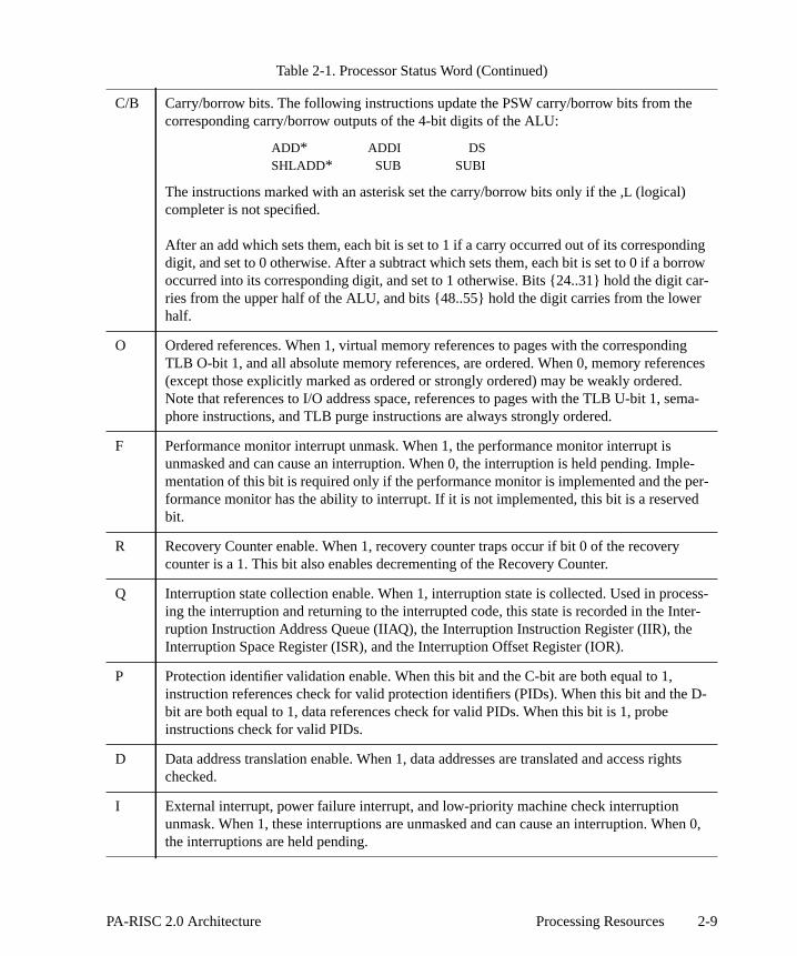
dingrrowar-r
gnces
ma-
le-per-d
ess-ter-
D-
hts
en 0,
C/B Carry/borrow bits. The following instructions update the PSW carry/borrow bits from thecorresponding carry/borrow outputs of the 4-bit digits of the ALU:
ADD* ADDI DSSHLADD* SUB SUBI
The instructions marked with an asterisk set the carry/borrow bits only if the ,L (logical)completer is not specified.
After an add which sets them, each bit is set to 1 if a carry occurred out of its correspondigit, and set to 0 otherwise. After a subtract which sets them, each bit is set to 0 if a booccurred into its corresponding digit, and set to 1 otherwise. Bits {24..31} hold the digit cries from the upper half of the ALU, and bits {48..55} hold the digit carries from the lowehalf.
O Ordered references. When 1, virtual memory references to pages with the correspondinTLB O-bit 1, and all absolute memory references, are ordered. When 0, memory refere(except those explicitly marked as ordered or strongly ordered) may be weakly ordered.Note that references to I/O address space, references to pages with the TLB U-bit 1, sephore instructions, and TLB purge instructions are always strongly ordered.
F Performance monitor interrupt unmask. When 1, the performance monitor interrupt isunmasked and can cause an interruption. When 0, the interruption is held pending. Impmentation of this bit is required only if the performance monitor is implemented and the formance monitor has the ability to interrupt. If it is not implemented, this bit is a reservebit.
R Recovery Counter enable. When 1, recovery counter traps occur if bit 0 of the recoverycounter is a 1. This bit also enables decrementing of the Recovery Counter.
Q Interruption state collection enable. When 1, interruption state is collected. Used in procing the interruption and returning to the interrupted code, this state is recorded in the Inruption Instruction Address Queue (IIAQ), the Interruption Instruction Register (IIR), theInterruption Space Register (ISR), and the Interruption Offset Register (IOR).
P Protection identifier validation enable. When this bit and the C-bit are both equal to 1,instruction references check for valid protection identifiers (PIDs). When this bit and thebit are both equal to 1, data references check for valid PIDs. When this bit is 1, probeinstructions check for valid PIDs.
D Data address translation enable. When 1, data addresses are translated and access rigchecked.
I External interrupt, power failure interrupt, and low-priority machine check interruptionunmask. When 1, these interruptions are unmasked and can cause an interruption. Whthe interruptions are held pending.
Table 2-1. Processor Status Word (Continued)
2-9PA-RISC 2.0 Architecture Processing Resources
tents ofectively.d. The
which
ontrol“Control
ts of a
Shadow Registers
There are seven registers shadow registers. Upon interruption, if the PSW Q-bit was 1, the conGRs 1, 8, 9, 16, 17, 24, and 25 are copied into shadow registers SHR 0, 1, 2, 3, 4, 5, and 6, respIf an interruption is taken with the PSW Q-bit equal to 0, the shadow registers are unchangecontents of these general registers are restored from their shadow registers when aRETURN FROMINTERRUPTIONinstruction with the (optional)R (for restore) completer is executed.
Control Registers
There are twenty-five defined control registers, numbered CR 0, and CR 8 through CR 31, contain system state information.
The control registers are shown in Figure 2-8 and described in the following sections. (The cregisters that can be accessed in the non-privileged state are described earlier in the section Registers (non-privileged)” on page 2-5.) Moving the contents of a control register to a generalregister copies the register contents right aligned into the general register. Moving the contengeneral register to a control register copies the entire general register into the control register.
Control registers 1 through 7 are reserved registers.
2-10 Processing Resources PA-RISC 2.0 Architecture

ery of counts The (seer trape value
Recovery Counter
The Recovery Counter (CR 0) is a 32-bit counter that can be used to provide software recovhardware faults in fault-tolerant systems, and can also be used for debugging purposes. CR 0down by 1 during the execution of each non-nullified instruction for which the PSW R-bit is 1.Recovery Counter is restored if the instruction terminates with a group 1, 2, or 3 interruptionChapter 4, “Control Flow”). When the leftmost bit of the Recovery Counter is 1, a recovery counteoccurs. The trap and the decrement operation can be disabled by setting the PSW R-bit to 0. Th
0 31 32 63
CR 0 nonexistent Recovery Counter
reserved
CR 8 Protection ID 1 WD Protection ID 2 WD
CR 9 Protection ID 3 WD Protection ID 4 WD
CR 10 reserved SCR CCR
CR 11 ignored SAR
CR 12 Protection ID 5 WD Protection ID 6 WD
CR 13 Protection ID 7 WD Protection ID 8 WD
CR 14 Interruption Vector Address reserved
CR 15 External Interrupt Enable Mask
CR 16 Interval Timer
CR 17 Interruption Instruction Address Space Queue
CR 18 Interruption Instruction Address Offset Queue
CR 19 reserved Interruption Instruction Register
CR 20 Interruption Space Register
CR 21 Interruption Offset Register
CR 22 Interruption Processor Status Word
CR 23 External Interrupt Request Register
CR 24 Temporary Register
•
•
•
CR 31 Temporary Register
Figure 2-8. Control Registers
2-11PA-RISC 2.0 Architecture Processing Resources

coverywritten is an
the
t
cessible(PIDs)ontrol”
WD- to have access
ining
which 7, and
g-pointst bit of0. Theresent,
nd theified innables
pondinge of ato 0 andit causesg to a
ds the7, andes bit
10, and
of the Recovery Counter may be read reliably only when the PSW R-bit is 0. (Reading the ReCounter when the PSW R-bit is 1 returns an undefined result.) The Recovery Counter may be reliably only when the PSW R-bit is 0. (Writing the Recovery Counter when the PSW R-bit is 1undefined operation.) If the PSW R-bit is set to 0 by either theRESET SYSTEM MASK or theMOVE TOSYSTEM MASK instruction, the Recovery Counter may not be read or written reliably prior toexecution of the eighth instruction after theRESET SYSTEM MASK or theMOVE TO SYSTEM MASKinstruction. An interruption, or aRETURN FROM INTERRUPTION instruction which sets the PSW R-bito 0, does not have this restriction.
Protection Identifiers
The protection identifiers (CRs 8, 9, 12, 13) designate up to eight groups of pages which are acto the currently executing process. When translation is enabled, the eight protection identifiers are compared with a page access identifier in the TLB entry to validate an access. (See “Access Con page 3-11.) The rightmost bit of each of the eight PIDs is the write disable (WD) bit. When thebit is 1, that PID cannot be used to grant write access. This allows each process sharing memorydifferent access rights to the memory without the overhead of changing the access identifier andrights in the TLB. When the PSW P-bit is 0, the PIDs, including the WD-bits, are ignored.
Each of the 8 PID registers can be from 16 to 32 bits wide (including the WD bit), with the remabits being reserved bits. The length of the PIDs is implementation dependent.
Coprocessor Configuration Register (CCR)
The Coprocessor Configuration Register or CCR (bits 56..63 of CR 10) is an 8-bit register records the presence and usability of coprocessors. The bit positions are numbered 0 throughcorrespond to a coprocessor with the same unit identifier. Bits 0 and 1 correspond to the floatincoprocessor, and bit 2 corresponds to the performance monitor coprocessor. Bit 7 is the rightmothe CCR. It receives bit 63 from a general register when a general register is written to CR 1upper 48 bits of CR 10, and bits within the CCR corresponding to coprocessors which are not pare reserved bits.
The behavior of the floating-point coprocessor with respect to the state of CCR bits 0 and 1 abehavior of the performance monitor coprocessor with respect to the state of CCR bit 2, are spec“Coprocessor Instructions” on page 6-22. For other coprocessors, setting a bit in the CCR to 1 ethe use of the corresponding coprocessor, if present and operational. If a CCR bit is 0, the correscoprocessor, if present, is logically decoupled. This decoupling must ensure that the statcoprocessor does not change as long as its corresponding CCR bit is 0. When a CCR bit is set an attempt is made to execute an instruction which references the corresponding coprocessor, an assist emulation trap. It is an undefined operation to set to 1 any CCR bit correspondincoprocessor which is not present.
SFU Configuration Register (SCR)
The SFU Configuration Register or SCR (bits 48..55 of CR 10), is an 8-bit register which recorpresence and usability of special function units. The bit positions are numbered 0 through correspond to an SFU with the same unit identifier. Bit 7 is the rightmost bit of the SCR. It receiv55 from a general register when a general register is written to CR 10. The upper 48 bits of CR bits within the SCR corresponding to SFUs which are not present, are reserved bits.
2-12 Processing Resources PA-RISC 2.0 Architecture

ent and ThisCR bit isces theponding20. It
rray ofservedan 64ss bits
ch ofhat bit
ctionss or
use in queues offsetm 32
ruptionation
formatpper was
)
For all SFUs, setting a bit in the SCR to 1 enables the use of the corresponding SFU, if presoperational. If an SCR bit is 0, the corresponding SFU, if present, is logically decoupled.decoupling must ensure that the state of an SFU does not change as long as its corresponding S0. When an SCR bit is set to 0 and an attempt is made to execute an instruction which referencorresponding SFU, it causes an assist emulation trap. The operation of an SFU when its corresSCR bit is 0 is explained in more detail in “Special Function Unit (SFU) Instructions” on page 6-is an undefined operation to set to 1 any SCR bit corresponding to an SFU which is not present.
Interruption Vector Address (IVA)
The Interruption Vector Address or IVA (CR 14) contains the absolute address of the base of an aservice procedures assigned to the interruption classes. The lower 11 bits of the IVA are reTherefore, the address written to it must be a multiple of 2048. For implementations with fewer thbits of physical address, the upper bits of the IVA corresponding to unimplemented physical addreare reserved. The array of interruption service procedures is indexed by the interruption numbersgiven in Chapter 4, “Control Flow”.
External Interrupt Enable Mask (EIEM)
The External Interrupt Enable Mask or EIEM (CR 15), is a 64-bit register containing a bit for eathe 64 external interrupts. Each 0 bit in the EIEM masks external interrupts corresponding to tposition.
Interruption Instruction Address Queues
The Interruption Instruction Address Space Queue or IIASQ (CR 17) and the Interruption InstruAddress Offset Queue or IIAOQ (CR 18) are collectively termed the interruption instruction addreIIA queues. They are used to save the Instruction Address and privilege level information for processing interruptions. The registers are arranged as two two-element deep queues. Thegenerally contain the addresses (including the privilege level field in the rightmost two bits of thepart) of the two instructions in the IA queues at the time of the interruption. The IIASQ may be froto 64 bits wide.
The IIA queues are continually updated whenever the PSW Q-bit is 1 and are frozen by an inter(PSW Q-bit becomes 0). After such an interruption, the IIA queues contain copies of the informfrom the IA queues. The IIAOQ contains the address offsets of the interruption point in the same as the IAOQ. The IIASQ has a different format from that of the IASQ. The IIASQ contains the uportion of the GVA (global virtual address) of the interruption point, if code address translationenabled. (Note that if the PSW W-bit was 0, the upper portion of the GVA is simply the space ID.
2-13PA-RISC 2.0 Architecture Processing Resources

ns theit was space
for thermed
ANDn the
If code address translation was disabled at the time of the interruption, then the IIAOQ contaiabsolute offsets of the interruption point, and the IIASQ contains zeros. (Note that if the PSW W-b0, the absolute offsets in the IIAOQ may be truncated to only those bits of the physical addressthat are implemented, and the upper bits forced to zeros.)
On a return from interruption, the values in the IIA queues are used to reform the IA queues return point. The values in the IIAOQ are copied to the IAOQ. The new values for the IASQ are foas follows (see also Figure 2-12): the lower 30 bits of the IASQ are formed by taking the bitwiseof the lower 30 bits of the values in the IIASQ with the complement of bits {2..31} of the values i
031
61
63
IIAOQOffset PL
Offset PL
063
IIASQGlobal Virtual Address {0..63}
Global Virtual Address {0..63}
Figure 2-9. Interruption Instruction Address Queues with Wide Virtual Addresses
031
61
63
IIAOQ0 Offset PL
0 Offset PL
063
IIASQSpace Identifier
Space Identifier
Figure 2-10. Interruption Instruction Address Queues with Narrow Virtual Addresses
031
61
63
IIAOQOffset PL
Offset PL
063
IIASQ0
0
Figure 2-11. Interruption Instruction Address Queues with Absolute Addresses
2-14 Processing Resources PA-RISC 2.0 Architecture

f theeforms
ns ofandIIASQitingof thefined
0. If an
ss to anR (CR. Theyin these set (or4 bits
g therm the {0..1} base
IIAOQ. Bits {32..33} of the IIASQ are copied to the same bits in the IASQ. The upper 32 bits oIIASQ (or as many as are implemented) are copied to the corresponding bits of the IASQ. This rthe original space identifiers.
Reading the IIAOQ (CR 18) while the PSW Q-bit is 0 retrieves the offset and privilege level portiothe front element in the IIAOQ. Writing into IIAOQ while the PSW Q-bit is 0 advances the IIAOQ then sets the offset and privilege level portions of the back element of the IIAOQ. Reading the (CR 17) while the PSW Q-bit is 0 retrieves the GVA portion of the front element of the IIASQ. Wrinto IIASQ while the PSW Q-bit is 0 advances the IIASQ and then writes into the back element IIASQ. The effect of reading or writing either queue register while the PSW Q-bit is 1 is an undeoperation.
The state contained in the IIA queues is undefined when aRETURN FROM INTERRUPTION instructionsets the PSW Q-bit to 0, or when system control instructions are used to set the PSW Q-bit to interruption is taken with the PSW Q-bit equal to 0, the IIA queues are unchanged.
Interruption Parameter Registers (IPRs)
The Interruption Parameter Registers (IPRs) are used to pass an instruction and a virtual addreinterruption handler. Three registers comprise the IPRs: the Interruption Instruction Register or II19), Interruption Space Register or ISR (CR 20), and Interruption Offset Register or IOR (CR 21)are used to pass an instruction and a virtual address to an interruption handler. The values registers for each interruption class are specified in Chapter 4, “Control Flow”. These values arefrozen) at the time of the interruption whenever the PSW Q-bit is 1. The ISR may be from 32 to 6wide.
The value loaded into the IOR is the lower 32 bits of the virtual address offset without truncatinrightmost bits or setting them to 0, plus the 2 bits of the base register which was used to foaddress. If the PSW W-bit was 1, the upper 2 bits of the IOR (called the b field) are equal to bitsfrom the base register. If the PSW W-bit was 0, the b field is equal to bits {32..33} from theregister. The other bits of the IOR are forced to 0.
Figure 2-12. Reforming Space Identifiers
GVA
Offset
Space Identifier
AND
Complement
IIAOQ
IIASQ
Restored IASQ value
2-15PA-RISC 2.0 Architecture Processing Resources

(Note
of ther bits in. If the
t is 0.lt.) The
If an
en anflects in the
en thehen a
trol
r eachnding
The value loaded into the ISR is the upper portion of the GVA, if data translation was enabled.that if the PSW W-bit was 0, the upper portion of the GVA is simply the space ID.)
If data translation was disabled at the time of the interruption, the IOR contains the lower 32 bitsabsolute offset. The upper 2 bits of the IOR are undefined, and may be set to any value. The othethe IOR are forced to 0. The ISR contains the upper portion of the absolute offset, zero-extendedPSW W-bit was 0 as well, the ISR contains 0.
The interruption parameter registers can be read or written reliably only when the PSW Q-bi(Reading an interruption parameter register when the PSW Q-bit is 1 returns an undefined resustate contained in the IPRs is undefined when aRETURN FROM INTERRUPTION instruction sets thePSW Q-bit to 0, or when system control instructions are used to set the PSW Q-bit to 0.interruption is taken with the PSW Q-bit equal to 0, the IPRs are unchanged.
Interruption Processor Status Word (IPSW)
The Interruption Processor Status Word or IPSW (CR 22) receives the value of the PSW whinterruption occurs. The format of the IPSW is identical to that of the PSW. The IPSW always rethe state of the machine at the point of interruption, regardless of the state of the PSW Q-bit. AsPSW, the unnamed bits are reserved bits.
The IPSW can be read or written reliably only when the PSW Q-bit is 0. (Reading the IPSW whPSW Q-bit is 1 returns an undefined result.) The state contained in the IPSW is undefined wRETURN FROM INTERRUPTION instruction sets the PSW Q-bit to 0, or when system coninstructions are used to set the PSW Q-bit to 0.
External Interrupt Request Register (EIRR)
The External Interrupt Request register or EIRR (CR 23) is a 64-bit register containing a bit foexternal interrupt. When 1, a bit designates that an interruption is pending for the correspo
0 231
63
IOR b 0 Offset {32..64}
063
ISR Global Virtual Address
Figure 2-13. Interruption Space and Offset Registers with Virtual Address
0 231
63
IOR un 0 Absolute Offset {32..64}
063
ISR 0 0 Absolute Offset {2..31}
Figure 2-14. Interruption Space and Offset Registers with Absolute Address
2-16 Processing Resources PA-RISC 2.0 Architecture

rityk (CR
ntlt in CR
IO_EIRrites to
s Wordregister.IR arehen thes 6-bit
uting aters for
ge level
nction
tion isust bese bits
may effect
valueystem
readnality.
RITE
external interrupt. Both the PSW I-bit (external interrupt, power failure interrupt, and low-priomachine check unmask) and the corresponding bit position in the External Interrupt Enable Mas15) must be 1 for an interruption to occur.
A MOVE TO CONTROL REGISTER instruction with CR 23 as its target bitwise ANDs the complemeof the contents of the source register with the previous contents of CR 23, and places this resu23. Thus the processor can only set the EIR register bits to 0.
A processor’s EIR register is also memory mapped into the physical address space as the Iregister to enable other processors and I/O modules to interrupt the processor. When a module wit, the bit specified by the value written is set to 1. The W bit (Wide enable) in the Processor Statu(PSW - see Table 2-1) determines whether the EIRR operates as a 32-bit register or a 64-bit When the W bit is 0, the EIRR operates effectively as a 32-bit register. Values written to the IO_Einterpreted as 5-bit numbers, which cause one of the bits in the range {32..63} to be set to 1. WW bit is 1, the EIRR operates as a 64-bit register. Values written to the IO_EIR are interpreted anumbers, which cause one of the bits in the range {0..63} to be set to 1.
Temporary Registers
Six of the eight 64-bit temporary registers (CRs 24, 25, 28..31) are accessible only by code execthe most privileged level. They provide space to save the contents of the general registinterruption handlers in the operating system kernel.
The other two temporary registers (CRs 26 and 27) are readable by code executing at any privileand writable only by code executing at the most privileged level.
Unused Registers and Bits
Currently, there are several registers and bit-fields within registers that do not have any fuassigned to them. All such processing resources are classified into four categories:
1. Reserved bits — Currently unused bits, but reserved for possible future use. A READ operalegal, and the value read back is all zeros. A WRITE operation is legal but the value written mall zeros. Writing ones is an undefined operation. (For example, writing ones may cause theto no longer read as zeros.)
2. Nonexistent bits — Architecturally these bits do not exist. A READ operation is legal andreturn zeros or what was last written. A WRITE operation is also legal but does not have anyon system functionality.
3. Undefined bits — Architecturally these bits are undefined. A READ operation is legal and theread is undefined. A WRITE operation is also legal but does not have any effect on sfunctionality.
4. Ignored bits — Architecturally these bits are ignored. A READ operation is legal and the valueis all zeroes. A WRITE operation is also legal but does not have any effect on system functio
5. Reserved registers — A register that is numbered but currently unused. Both READ and Woperations are undefined operations.
2-17PA-RISC 2.0 Architecture Processing Resources

rs, andsed by
rt is
value5, an
Data Types
The fundamental data types that are recognized are bits, bytes, integers, floating-point numbedecimal numbers. Their formats are described briefly in this section. Each item of data is addresits lowest-numbered byte.
Bits Memory is not addressed to the resolution of bits; however, efficient suppoprovided to manipulate and test individual bits in the general registers.
Bytes Bytes are signed or unsigned 8-bit quantities:
Bytes are packed four to a word and may represent a two’s complement signedin the range -128 through +127, an unsigned value in the range 0 through 25arbitrary collection of eight bits, or an ASCII character.
Integers Integers may be 16, 32, or 64 bits wide, signed or unsigned:
Signed Byte
s value
1 7
Unsigned Byte
value
8
Signed Halfword
s value
1 15
Unsigned Halfword
value
16
Signed Words value1 31
Unsigned Wordvalue
32
Signed Doublewords value1 63
2-18 Processing Resources PA-RISC 2.0 Architecture

d invisible
54-ord
ries.wordn on
23, or0x9,
ll beis not
n bytelower- is 1, allpond to
e E-bit.
oftwarer 1 onendian” on
ndian
Signed integers are in two’s complement form. Halfword integers can be storememory only at even byte addresses, word integers only at addresses evenly diby four, and doubleword integers only at addresses evenly divisible by eight.
Floating-Point Numbers
The binary floating-point number representation conforms to the ANSI/IEEE 71985 standards. Single-word (32-bit), double-word (64-bit), and quadruple-w(128-bit) binary formats are supported.
Single-precision floating-point numbers must be aligned on word boundaDouble-precision and quad-precision numbers must be aligned on doubleboundaries. See Chapter 8, “Floating-point Coprocessor”, for detailed informatiothe floating-point formats.
Packed Decimal Numbers
Packed decimal data is always aligned on a word boundary. It consists of 7, 15, 31 BCD digits, each four bits wide and having a value in the range of 0x0 to followed by a 4-bit sign as shown in the following figure:
The standard sign for a positive number is 0xC, but any value except 0xD wiinterpreted as positive. 0xD indicates a minus sign for a negative number. 0xB supported as an alternative minus sign.
Byte Ordering (Big Endian/Little Endian)
The optional E-bit in the PSW controls whether loads and stores use big endian or little endiaordering. When the E-bit is 0, all larger-than-byte loads and stores are big endian — the addressed bytes in memory correspond to the higher-order bytes in the register. When the E-bitlarger-than-byte loads and stores are little endian — the lower-addressed bytes in memory corresthe lower-order bytes in the register. Load byte and store byte instructions are not affected by thThe E-bit also affects instruction fetch.
Processors which implement the PSW E-bit must also provide an implementation-dependent, swritable default endian bit. The default endian bit controls whether the PSW E-bit is set to 0 ointerruptions and also controls whether data in the page table is interpreted in big endian or little format by the hardware TLB miss handler, if implemented (See “Hardware TLB Miss Handlingpage F-3).
Figure 2-15 shows various loads in big endian format. Figure 2-16 shows various loads in little e
Unsigned Doublewordvalue
64
MSD • • • LSD sign
4 4 4 4
2-19PA-RISC 2.0 Architecture Processing Resources

ower-bit is 1,-order
format. Stores are not shown but behave similarly.
The E-bit also affects instruction fetch. When the E-bit is 0, instruction fetch is big endian — the laddressed bytes in memory correspond to the higher-order bytes in the instruction. When the E-instruction fetch is little endian — the lower-addressed bytes in memory correspond to the lowerbytes in the instruction.
Figure 2-15. Big Endian Loads
Figure 2-16. Little Endian Loads
a
b
c
d
e
f
g
h
0 b0 0
e hf ga db c
0 31
0 d0 c
0 31
e hf g
0 31
0 63
0
1
2
3
4
5
6
7
LDBS 1(0,0),t
LDHS 2(0,0),t
LDWS 4(0,0),t
FLDDS 0(0,0),t
0 7
Memory Registers
a
b
c
d
e
f
g
h
0 b0 0
d ac bh eg f
0 31
0 c0 d
0 31
h eg f
0 31
0 63
0
1
2
3
4
5
6
7
LDBS 1(0,0),t
LDHS 2(0,0),t
LDWS 4(0,0),t
FLDDS 0(0,0),t
0 7
Memory Registers
2-20 Processing Resources PA-RISC 2.0 Architecture

reli
re
Architecturally, the instruction byte swapping can occur either when a cache line is moved into theinstruction cache (I-cache) or as instructions are fetched from the I-cache into the pipeline.
Processors must support running code with either endian form from the same cache line. This evessoftware of the responsibility of keeping track of what might have been brought in under differentforms.
Engineering NoteFor processors which swap instructions on I-cache move-in, one way to meet this requirementis to implement endian tag bits and force a miss if the tag does not match the current value ofPSW[E].
Processors which swap instructions as they are fetched from the I-cache do not need to doanything extra to meet this requirement.
Since the PSW E-bit is an instruction fetch resource (see “Instruction Pipelining” on page4-9), SETSYSTEM MASK, RESET SYSTEM MASK or MOVE TO SYSTEM MASK instructions which change thePSW E-bit must be followed by seven palindromic NOP instructions — that is, instructions which aNOPs when interpreted in either big or little endian order
Programming NoteOne example of a palindromic NOP instruction is LDI 26,0 (opcode 0x34000034)
2-21PA-RISC 2.0 Architecture Processing Resources

2-22 Processing Resources PA-RISC 2.0 Architecture

ol
gisters aret holdcalled
gh notal pages an I/Oel and
e given
the I/Oresses areaccessesectly, noare called
y), andnerate
hanisms.values
can bee physicalesses are
:
ce 15
FFFFFesents 1/
F canesent
3 Addressing and Access Contr
Data storage is organized as a storage hierarchy based on speed of access: user-accessible reat the highest level followed by the memory system which consists of high-speed buffers tharecently referenced instructions and/or data, and main memory. The high-speed buffers, instruction and/or data caches, reduce the effective access time to main memory.
The I/O system is memory-mapped with I/O modules mapped into physical pages that, althoupart of the main memory, are addressed in the same way. With virtual pages mapped into physicand I/O registers represented by words in a page, communication between a processor andmodule can be performed with load and store instructions to virtual addresses. The privilege levaccess rights of such a page provide versatile protection. Non-privileged code may therefore bdirect access to some I/O modules without compromising system security.
PA-RISC processors use byte addressing to fetch instructions and data from main memory or registers. The byte addresses may be either virtual addresses or absolute addresses. Virtual addtranslated to absolute addresses and undergo protection and access rights checking. Memory using virtual addresses are called virtual accesses. When absolute addresses are used dirprotection or access rights checks are performed. Memory accesses using absolute addresses absolute accesses.
The instructions that reference memory are load (memory-to-register), store (register-to-memorsemaphore instructions. Additionally, several system control and cache-related instructions geaddresses that use the address translation, protection, and access rights checking mecComputation instructions do not reference memory, but perform data transformations by using obtained from general registers and returning results to these registers.
Physical and Absolute Addressing
Objects in the main memory and I/O system reside in a 64-bit physical address space and accessed using byte addresses which may be either virtual addresses or absolute addresses. Thaddress space and absolute accesses are described in the paragraphs that follow. Virtual accdescribed later in this chapter.
Physical Address Space
The Physical Address Space is 64 bits in size as shown in Figure 3-1 and has three components
• Memory Address Space - Addresses 0 through 0xEFFFFFFF FFFFFFFF can referenExabytes of memory. This space represents 15/16ths of the Physical Address Space.
• PDC Address Space - Addresses 0xF0000000 00000000 through 0xF0FFFFFF FFFreference Processor Dependent Code (PDC) and it associated resources. This space repr256th of the Physical Address Space.
• I/O Address Space - Addresses 0xF1000000 00000000 through 0xFFFFFFFF FFFFFFFreference nearly 1 Exabyte of I/O registers. The I/O and PDC Address Spaces together repr1/16th of the Physical Address Space.
3-1PA-RISC 2.0 Architecture Addressing and Access Control

e only bits of
f the
mostdress64-bit
Although software views the Physical Address Space as being 64 bits in size, implementations arrequired to support physical address spaces between 32 and 64 bits in size. If less than 64physical address space are supported, the following rules must be observed:
• The Memory, PDC, and I/O Address Spaces must each occupy the same fraction oimplemented physical address space as they do in the 64-bit physical address space, as shown inFigure3-2.
• In an n-bit physical address space implementation, implementations must ignore thesignificant 64-n bits of a 64-bit physical address for references to the Memory and I/O AdSpaces. For references to the PDC Address Space, implementations may transform a physical address into an n-bit physical address in a processor-specific fashion provided the eightmost significant bits of both addresses are identical.
Figure 3-1. 64-bit Physical Address Space
PDC AddressSpace
MemoryAddress Space
0xF000000 0 00000000
0xF100000 0 00000000
0xFFFFFFFF FFFFFFFF
0x0000000 0 00000000
I/O AddressSpace
1516------
1256---------
116------
3-2 Addressing and Access Control PA-RISC 2.0 Architecture

is 0 for
of the lowest-
Absolute Accesses
Accesses made withLOAD WORD ABSOLUTE andSTORE WORD ABSOLUTE instructions, or whenvirtual address translation is disabled (the PSW D-bit is 0 for data accesses or the PSW C-bit instruction accesses) are called absolute accesses.
Absolute Accesses when PSW W-bit is 1
When the PSW W-bit is 1 (see “Processor Status Word (PSW)” on page 2-7 for the definition PSW W-bit), an absolute address is a 62-bit unsigned integer whose value is the address of theaddressed byte of the operand it designates (see Figure 3-3).
Figure 3-2. n-bit Physical Address Space Implementation
ne Absolute Byte Address
2 62
Figure 3-3. 62-bit Absolute Pointer
PDC AddressSpace
MemoryAddress Space
2n-2 n-4
2n-2 n-4 +2n-8
2n-1
0
I/O AddressSpace
1516------
1256---------
116------
3-3PA-RISC 2.0 Architecture Addressing and Access Control

on for
dress of
on for
ugh theords (2own in
at anyiples of 4, is used,
ccessed
Refer to “Absolute Accesses when PSW W-bit is 1” on page H-10 for details on address formatithese accesses.
Absolute Accesses when PSW W-bit is 0
When the PSW W-bit is 0, an absolute address is a 32-bit unsigned integer whose value is the adthe lowest-addressed byte of the operand it designates (see Figure 3-4)
Refer to “Absolute Accesses when PSW W-bit is 0” on page H-11 for details on address formatithese accesses.
Memory Addressable Units and Alignment
Memory is always referenced with byte addresses, starting with address 0 and extending throlargest defined non-I/O address (0xEFFFFFFF FFFFFFFF). Addressable units are bytes, halfwbytes), words (4 bytes), and doublewords (8 bytes). A comparison of the addressable units is shFigure 3-5 with the relative byte numbers indicated inside the blocks.
All addressable units must be stored on their naturally aligned boundaries. A byte may appearaddress, halfwords must begin at even addresses, words must begin at addresses that are multand doublewords must begin at addresses that are multiples of 8. If an unaligned virtual addressan interruption occurs.
Bits within larger units are always numbered from 0 starting with the most significant bit.
I/O address space is referenced in doublewords, words, halfwords, and bytes. I/O registers are ausing the normal load and store instructions.
non-existent Absolute Byte Address
32 32
Figure 3-4. 32-bit Absolute Pointer
Figure 3-5. Physical Memory Addressing and Storage Units
0
0 4
0 2 4 6
0 1 2 3 4 5 6 7Bytes
Halfwords
Words
Doublewords
increasing byte
addresses
3-4 Addressing and Access Control PA-RISC 2.0 Architecture

entifierspace of ther 34
hene GVAcated,
t. Theer the.)
TLBs),for ass may
ize. Users with
addressnd 62 bitsith 32-2-bitor a 96-iently
Virtual Addressing
Virtual memory is organized into linear spaces. These spaces can range in size from 232 bytes each to264 bytes each. The object within the space is specified by a 32-bit to 64-bit offset. The space idis combined with the offset to form a complete global virtual address (GVA.) The offset and portions are aligned as shown, and bits 34..63 of the space are ORed together with bits 2..31offset to form the GVA. The lower 32 bits of the GVA come directly from the offset, and the uppebits come directly from the space.
A bit in the Processor Status Word (PSW[W]) provides compatibility with older programs. WPSW[W] is 0, offsets are truncated to 32 bits (the upper 32 bits of the offset are forced to 0). This then formed in the same way, by ORing the offset with the space. Since the offset is trunthough, this is simply equivalent to concatenating the space with the lower 32 bits of the offset.
Implementations also provide an implementation-dependent, software-writable default width bidefault width bit controls whether the PSW W-bit is set to 0 or 1 on interruptions, and also whethEIRR is treated as a 32-bit or a 64-bit register. (See “Processor Status Word (PSW)” on page 2-7
Translation from virtual to absolute addresses is accomplished by translation lookaside buffers (which are described in Chapter 3, “Addressing and Access Control”. Fields in the TLB entry particular page permit control of access to the page for reading, writing or execution. Such accebe restricted to a single process, or a set of processes, or may be permitted to all processes.
To a user application, the virtual address space appears to be flatly addressable and 64 bits in sapplications are concerned only with the 64-bit address offset. Full support for 32-bit application32-bit pointers is also provided.
To Operating System software, the address space can be thought of as consisting of a set ofspaces, each with its own space identifier, and where each address space can be between 32 ain size, depending on the needs of the individual application. For example, an implementation wbit space identifiers would allow for 4 billion 32-bit spaces, or 1 million 44-bit spaces, or 4 6spaces, or any combinations of these. Space identifiers can range up to 64 bits in size, allowing fbit virtual address. The virtual address model in PA-RISC provides a powerful means for efficmanaging a large address space.
0 231
61
63
offset a A B
032
34
63
space C d D
GVA C d A | D B
Figure 3-6. Global Virtual Address Formation
3-5PA-RISC 2.0 Architecture Addressing and Access Control

of which by theates the
tructioncess to offset,
gle 64-dress.
ly, the control
maphoreand dataegister
For memory management purposes, the address space is logically subdivided into pages, each can range in size from 4 Kbytes to 64 Mbytes in length. The byte offset into the page is specifiedleast significant 12 to 26 bits of the virtual address, depending on the page size. Figure 3-7 illustrstructure of spaces, pages, and offsets.
Pointers and Address Specification
For virtual accesses, addresses can be specified two different ways. With explicit pointers, an inscomputes an address offset and explicitly specifies a space identifier. This provides efficient acthe entire global virtual address space. With implicit pointers, an instruction computes an addressand this offset calculation implicitly specifies a space ID. This provides the appearance of a sinbit (or 32-bit) flat address space. The offset and space ID are combined to form the full virtual ad
Eight Space Registers hold space identifiers used in forming virtual addresses. AdditionalInstruction Address Space Queue holds the space ID for the current instruction address, and tworegisters are used to hold space ID information after interruptions.
Data Addresses
Data addresses are computed for regular memory reference instructions (load, store, and seinstructions) and for system instructions used in managing the address space (access probe, cache and data TLB control instructions). A 64-bit offset is calculated by adding a 64-bit base r
Figure 3-7. Structure of the Virtual Address Space
Space ID
Offset
Virtual Memory
4 KB - 64 MB Pages296 Bytes
Virtual Address
OR
3-6 Addressing and Access Control PA-RISC 2.0 Architecture

isters is the
ence and
ough 7.implicitvirtual
branchanaging
e byteurrentuction
ress (asm oneisters 4
.
plus a 64-bit index register or a sign-extended immediate displacement. One of the Space Regselected, either implicitly, by the top two bits of the base register, or explicitly, by a field ininstruction. The space ID is then logically ORed with the offset of form the virtual address.
The space identifier is selected from Space Registers 1 through 7 as follows, based on the presvalue of the 2-bits field in the memory reference instruction.
• If the instruction does not have ans field, or if the value of thes field is zero, space ID selection isimplicit. The top two bits of the base register are used to select one of Space Registers 4 thrThis permits the addressing of four distinct spaces selected by program data, and is called pointer addressing, since a regular 64-bit value specifies the offset and space ID for a full address.
• If the instruction does have ans field, and the value of thes field is non-zero, the s-field explicitlyselects one of Space Registers 1, 2 or 3. Figure 3-8 illustrates space identifier selection.
Instruction Addresses
Instruction addresses for instruction fetch are computed from the IA queues and as a result oftarget calculations. Instruction addresses are also computed for system instructions used in mthe address space (instruction cache and instruction TLB control instructions).
The current instruction address (IA) consists of a space identifier and a 64-bit byte offset. Thoffset is a word-aligned address and contains, in its least significant two bit positions, the cprivilege level. This privilege level controls both instruction and data references. The current instraddress is maintained in the front elements of the Instruction Address Queues (IA queues).
In forming instruction addresses, the space ID can either remain unchanged from the last addwith in-line instruction fetching and with intraspace branches), or the space ID can be selected froof the Space Registers. The selection of the Space Register is either implicit (one of Space Regthrough 7 selected by the top two bits of the base register), explicit with a 2-bits field, like dataaddressing (one of SRs 1, 2 or 3 selected by the instruction), or explicit with a 3-bits field (one of SRs 0through 7 selected by the instruction). See Figure 3-8.
As with data addresses, the space ID is logically ORed with the offset to form the virtual address
Executing or branching beyond the end of the current space is undefined.
3-7PA-RISC 2.0 Architecture Addressing and Access Control

Statusoffset. Spaceas in
addressis formeds offsetto a 32-
PA-
d from thess spacef not alle, and the
32-bit Addresses
Programs which use 32-bit data and 32-bit pointers are fully supported. A bit in the ProcessorWord (PSW W-bit) is used to control address formation. For 32-bit programs, address calculations are done just as for 64-bit programs, but then the offset is truncated to a 32-bit valueidentifier selection for implicit pointers is done with the upper two bits of the lower 32-bits, just PA-RISC 1.1.
For 32-bit PA-RISC 1.1 programs that directly manipulate space identifiers to gain access to an space larger than 32 bits, Space Registers appear to be 32 bits in size, and the virtual address just as in PA-RISC 1.1. (The space identifier is concatenated with the lower 32-bits of the addresto form the virtual address. This happens automatically as a result of the offset being truncated bit value.)
In brief, the addressing model of PA-RISC 2.0 is fully compatible with 32-bit programs written forRISC 1.1.
Absolute Addresses
For absolute accesses, the space identifiers are unused, and the absolute address is calculateoffset alone. If the most significant 4 bits of the offset are 1, the address accesses the I/O addreand the absolute address is simply equal to the offset. (See “Absolute Accesses” on page 3-3.) Iof the most significant 4 bits of the offset are 1, the address accesses the memory address spac
Figure 3-8. Space Identifier Selection
SR[1]
SR[2]
SR[3]
Space Registerss-field
Space ID
SR[0]
SR[1]
SR[2]
SR[3]
SR[4]
SR[5]
SR[6]
SR[7]
Space Registers
SR[4]
SR[5]
SR[6]
SR[7]
Space ID
Space Registers
2
4
GR[b]
Space ID
s-field
3
2 3
Implicit pointeraddressing
Explicit pointeraddressing
with 2-bit s-field
Explicit pointeraddressing
with 3-bit s-field
3-8 Addressing and Access Control PA-RISC 2.0 Architecture
spaceress.
anslationysical for may
es ined, fromentry.slation
ber. Ifenatedform a miss
thestartsed to
d therts theurs inve or dueoftware
lation.support
absolute address is formed by taking the offset and forcing the most significant 2 bits to 0.
This way of forming absolute address for memory allows software more flexibility in address layout. Note that this has no impact on machine implementing fewer than 62 bits of physical add
Address Resolution and the TLB
Virtual addresses are translated to absolute addresses using a hardware structure called the TrLookaside Buffer (TLB). A TLB accepts a Virtual Page Number and returns the corresponding PhPage Number. The TLB is organized as two parts. The instruction TLB (ITLB) is only usedinstruction references, while the data TLB (DTLB) is only used for data references. A systemimplement a combined TLB which is used for both instruction and data references.
A TLB is typically not large enough to hold all the current translations. Translations for all pagmemory are stored in a memory structure called the Page Table. Multiple page sizes are support4 Kbytes to 64 Mbytes. This allows large contiguous regions to be mapped with a single TLB This increases the virtual address range of the TLB, thereby minimizing the virtual address tranoverhead.
Given a virtual address, the selected TLB is searched for an entry matching the Virtual Page Numthe entry exists, the 38 to 52-bit Physical Page Number (contained in the TLB entry) is concatwith the original 12 to 26-bit page offset (depending on the page size in the matching entry) to 64-bit absolute address. If no such entry exists, the TLB is updated by either software TLBhandling or hardware TLB miss handling.
In systems with software TLB miss handling, a TLB miss fault interruption routine performstranslation, explicitly inserts the translation and protection fields into the appropriate TLB, and rethe interrupted instruction. To insure the completion of instructions, the TLBs must be organizsimultaneously hold all necessary translations.
In implementations that provide hardware for TLB miss handling, the hardware attempts to finvirtual to physical page translation in the Page Table. If the hardware is successful, it insetranslation and protection fields into the appropriate instruction or data TLB. No interruption occthis case. If hardware is not successful, due to a search of the Page Table that was not exhaustito the appropriate translation not existing in the Page Table, an interruption occurs so that the scan complete the process.
The translation lookaside buffer performs other functions in addition to the basic address transThe other functions include access control, program debugging support and operating system for virtual memory. Figure 3-9 summarizes the information maintained for each TLB entry.
3-9PA-RISC 2.0 Architecture Addressing and Access Control

plicitly] bit ises” on
movedaddressp to thehere I/O line. is an” on
eference
o trape been
phore if
staticed on as a
in the
The following describes the function of each of the 1-bit fields.
O Ordered. When 0, data memory references using this translation (except those exmarked as ordered or strongly ordered) may be weakly ordered. When 1 and the PSW[O1, data memory references using this translation are ordered. See “Ordering of Referencpage G-1.
U Uncacheable. When 0, data references to a page from memory address space may beinto the cache. When 1, data references to a page from I/O address space or memory space must not be moved into the cache. The U-bit must be set to 1 for pages which maI/O address space, and is commonly set to 1 for pages in the memory address space wmodule written data and processor written data must co-exist within the same cacheReferencing a page which maps to the I/O address space and for which the U-bit is 0undefined operation. Implementation of the U-bit is optional. See “Data Cache Move-Inpage F-8 for additional details.
T Page Reference Trap. When 1, data references using this translation cause a page rtrap. The T-bit is most commonly used for program debugging.
D Dirty. When 0, store and semaphore instructions cause a TLB dirty bit trap. When 1, noccurs. The D-bit may be used by the operating system to determine which pages havmodified.
B Break. When 1, instructions that could modify data using this translation (store and semainstructions, and thePURGE DATA CACHE instruction) cause a data memory break trap,enabled. The B-bit is most commonly used for program debugging.
P Prediction method for branching. When 0, branch prediction is performed based onprediction hints encoded in the instructions. When 1, branch prediction is performed basdynamic prediction hardware, on implementations so equipped. This bit functions solelyperformance hint. Implementation of the P-bit is optional.
Since the ITLB is not used for data operands, the O, U, T, D, and B bits are only implemented
Virtual Page Number
52 to 84 bits
Physical Page Number
52 bits
Page Size
4 bits
Access Rights
7 bits
Access ID
15 to 31 bits
O U T D B P Single-Bit Flags
Figure 3-9. TLB Fields
3-10 Addressing and Access Control PA-RISC 2.0 Architecture

nted
ght intodwares with TLB
trol
re and
age isB with a page
tecture’snd TLBailable
d. If the is notportedth dataave the
DTLB or a combined TLB. Similarly, since the P-bit controls branch prediction, it is only implemein the ITLB or combined TLB.
The TLB is managed by a mixture of hardware and software mechanisms. Translations are brouthe TLB by either hardware or software when a TLB miss occurs. In systems which provide harfor TLB miss handling, the Page Table holds the information needed for the TLB. For systemsoftware TLB miss handling, and for explicit insertion of a translation by systems with hardwaremiss handling, TLB management instructions provide the TLB with this information. TheINSERTINSTRUCTION TLB TRANSLATION instruction places the complete translation and access coninformation into the ITLB. A similar instruction (INSERT DATA TLB TRANSLATION) places thecomplete translation and access control information and also initializes the system softwadebugging support bit fields in the DTLB.
TLB miss traps do not occur on nullified instructions.
Page Size
The TLBs support a range of page sizes, in multiples of four, from 4 Kbytes to 64 Mbytes. Each paligned to an address which is an integer multiple of its size. The page size is inserted into the TLeach translation, and is encoded as shown in Table 3-1. TLB purge instructions can also specifysize, allowing a large contiguous address range to be purged in a single instruction.
Access Control
User processes can be provided with a secure and protected environment via a part of the archiaddress translation mechanism. Processor resources, including the PSW, Control Registers, aentries, contain information used to determine the allowed use of a page. Access control is avonly when address translation is enabled, and is done on a per-page basis.
An access is validated if the check of the access rights and the protection identifiers both succeeaccess is validated, the instruction reference or data reference is completed. If the accessvalidated, the instruction is terminated with a protection trap. Instruction access violations are rewith instruction memory protection traps. Data read and write access violations are reported wimemory access rights or data memory protection ID traps. Probe instructions are special; they s
Table 3-1. Page Sizes
Encoding Page size
0 4 KB1 16 KB2 64 KB3 256 KB4 1 MB5 4 MB6 16 MB7 64 MB8-15 Reserved
3-11PA-RISC 2.0 Architecture Addressing and Access Control

ss rights check within
e of thess by theof the
ed 0,astQ).
ivilegeege
probe probe
s. Noteds. An
ctione used bit ofatch ID.
datadress
henses the
result of the access validation in a General Register and do not cause a protection trap. An accecheck is based on the type of access and the current privilege level. The protection identifiercompares the Protection ID Registers with a page-based access identifier in the TLB. State bitsthe PSW determine when these checks are enabled.
Process Attributes
The type of access, privilege level, the current values in the Protection ID Registers, and the statPSW completely describes the access to the TLB. These resources are managed for each proceoperating system and collectively termed the process attributes. The following defines each process attributes.
Privilege Level (PL)
Every instruction is fetched and executed at one of four privilege levels (number1, 2, 3) with 0 being the most privileged. The privilege level is kept in the lesignificant two bits of the current instruction’s address (the front element of IAOFor all accesses, except the probe instructions, the privilege check uses the prlevel of the current instruction. The probe instructions explicitly specify the privillevel to be used in the access rights check.
Access type
The access type is either read, write, or execute. Load, semaphore, and readinstructions make read accesses to their operands. Store, semaphore and writeinstructions and cache purge operations make write accesses to their operandthat semaphore instructions make both read and write accesses to their operanexecute access occurs when an instruction is fetched for execution.
Protection IDs
The four Control Registers CR 8, CR 9, CR 12, and CR 13 contain the proteidentifiers associated with the current process (Figure 3-10). These registers arto allow several different protection groups to be accessed. The least significanteach protection ID is the write-disable (WD) bit. When 0, write accesses that mthat protection ID are allowed. The remaining 15 to 31 bits hold the protectionFigure 3-10 depicts the maximum width of the protection identifier.
PSW access attributes
The PSW protection validation (P-bit), code address translation (C-bit), and address translation (D-bit) bits further qualify the process attributes. When adtranslation is enabled and the P-bit is 1, the protection ID check is performed. W0, the protection ID check is always considered successful. An execute access u
0 30 31
Protection ID WD
31 1
Figure 3-10. Protection ID
3-12 Addressing and Access Control PA-RISC 2.0 Architecture

hen 1,hen 0,
d writedress
e state
allowed.on ID of the
neededay bed PL2accessute, orub-field
e TLBprivileged probe
pe field
o moress. The
hecktches this. This
e level
ith the
C-bit to determine if address translation and access rights check are enabled. Waddress translation is performed and execute access rights checks are made. Wno address translation is performed and the access is always allowed. Read anaccesses use the D-bit in an equivalent manner. For probe instructions, adtranslation is performed, and access rights checks are made independent of thof the PSW D-bit.
Access ID and Access Rights
For each entry in the TLB, the access ID and the access rights fields determine if an access is The access ID is a 15- to 31-bit field in the TLB that is used with the protection IDs in the protecticheck. The length of the access ID is implementation dependent but must match the lengthprotection ID (excluding the WD bit).
The access rights field (Figure 3-11) is a 7-bit field that encodes the allowed access types and theprivilege levels. In some cases a minimum privilege is specified, while other access types mspecified with an upper and a lower bound. The three sub-fields type, PL1 (privilege level 1), an(privilege level 2) combine to form the access rights field. The type sub-field defines the type of that can be made to this page. Any of read-only, read/write, read/execute, read/write/execexecute-only is allowed. The PL1 sub-field qualifies read and execute accesses. The PL2 squalifies write and execute accesses.
The access rights check compares the current privilege level with the appropriate sub-field of thaccess rights field and checks if the type of access is allowed. For a read access, the current level must be at least as privileged as PL1 and the type field must allow read access. The reainstructions explicitly specify the privilege level.
For a write access, the current privilege level must be at least as privileged as PL2 and the tymust allow write access. The write probe instructions explicitly specify the privilege level.
For an execute access, the current privilege level must be at least as privileged as PL1 and nprivileged than PL2. PL1 and PL2 are a lower and an upper bound, respectively, for execute accetype field must also allow execute access.
For thePURGE DATA CACHE instruction, if implemented as a purge operation, the access rights chas a special case. The access rights check is done normally, except that if the access rights mabinary pattern: “111 0X 1X” (where each X stands for either a 1 or a 0), then access is allowedfacilitates cache management. See “Cache Flushing” on page F-10. IfPURGE DATA CACHE isimplemented as a flush operation, then no access rights check is performed.
The type field is also used by theBRANCH instruction with the ,GATE (for gateway) completer tospecify the new privilege level. When the type value is 4 or greater and the encoded new privilegis of greater privilege, then promotion occurs at the target of the branch.
Table 3-2 defines the type encodings and the necessary conditions of the PL1 and PL2 fields w
Type PL1 PL2
3 2 2
Figure 3-11. Access Rights Field
3-13PA-RISC 2.0 Architecture Addressing and Access Control
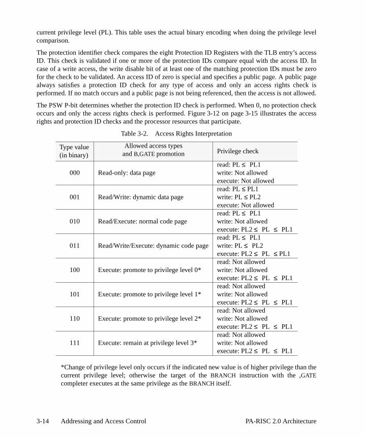
level
ccessID. Inbe zerolic pageheck isallowed.
check access
the
current privilege level (PL). This table uses the actual binary encoding when doing the privilegecomparison.
The protection identifier check compares the eight Protection ID Registers with the TLB entry’s aID. This check is validated if one or more of the protection IDs compare equal with the access case of a write access, the write disable bit of at least one of the matching protection IDs must for the check to be validated. An access ID of zero is special and specifies a public page. A pubalways satisfies a protection ID check for any type of access and only an access rights cperformed. If no match occurs and a public page is not being referenced, then the access is not
The PSW P-bit determines whether the protection ID check is performed. When 0, no protectionoccurs and only the access rights check is performed. Figure 3-12 on page 3-15 illustrates therights and protection ID checks and the processor resources that participate.
*Change of privilege level only occurs if the indicated new value is of higher privilege thancurrent privilege level; otherwise the target of theBRANCH instruction with the ,GATEcompleter executes at the same privilege as theBRANCH itself.
Table 3-2. Access Rights Interpretation
Type value(in binary)
Allowed access typesandB,GATE promotion Privilege check
000 Read-only: data pageread: PL≤ PL1write: Not allowedexecute: Not allowed
001 Read/Write: dynamic data pageread: PL≤ PL1write: PL≤ PL2execute: Not allowed
010 Read/Execute: normal code pageread: PL≤ PL1write: Not allowedexecute: PL2≤ PL ≤ PL1
011 Read/Write/Execute: dynamic code pageread: PL≤ PL1write: PL≤ PL2execute: PL2≤ PL ≤ PL1
100 Execute: promote to privilege level 0*read: Not allowedwrite: Not allowedexecute: PL2≤ PL ≤ PL1
101 Execute: promote to privilege level 1*read: Not allowedwrite: Not allowedexecute: PL2≤ PL ≤ PL1
110 Execute: promote to privilege level 2*read: Not allowedwrite: Not allowedexecute: PL2≤ PL ≤ PL1
111 Execute: remain at privilege level 3*read: Not allowedwrite: Not allowedexecute: PL2≤ PL ≤ PL1
3-14 Addressing and Access Control PA-RISC 2.0 Architecture

of thesecribed in
s after arward
Page Table Structure
Address translations are stored in memory in a structure called the Page Table. The exact form tables is a software convention, but many aspects of the page tables are common and are desthis section.
The most common use of the Page Table is to translate a virtual address to a physical addresTLB miss. The virtual address space is quite large, and a traditional approach of a multi-level fo
Figure 3-12. Access Control Checks
ProtectionID 8
ProtectionID 7
ProtectionID 3
ProtectionID 4
Control Registers
AccessAllowed?
8
9
12
13
TLB
Access ID
Access Rights
ProtectionCheck?
Access RightsCheck?
Type ofAccess
(read/write/execute)
PSWIA queues
P
YesYes
Yes
PL
ProtectionID 1
ProtectionID 2
ProtectionID 5
ProtectionID 6
3-15PA-RISC 2.0 Architecture Addressing and Access Control

o many
virtualuniformultiple
or some
e entry
rocessor
valid
s (see
ons and
mapped table, where each level is directly indexed by a portion of the virtual address, requires tomemory accesses and hence is an inefficient way to provide virtual to physical translations.
A better approach is to index the Page Table using the result of a hash function applied to theaddress. The purpose of the hash function is to translate virtual addresses to a smaller, more name space. The particular function used is implementation dependent. Collisions created by maddresses hashing to the same entry can be resolved using a sequentially searched linked listother structure.
The number of entries in the Page Table is typically a power of two. One possible format of a tablis shown in Figure 3-13.
The fields are:
V is the valid bit. If V = 1, this entry represents a valid translation.
Tag is a unique key used to identify the virtual address that this entry translates.
R is the reference bit. If R = 1, the page has been accessed (read, write, or execute) by a psince the bit was last cleared to 0.
Physical Page Number
is the physical page number corresponding to the virtual address, provided this entry isand the virtual address matches the tag.
Size is the page size, encoded as in Table 3-1 on page 3-11.
Next Page Table Entry
is an index/pointer to perhaps another structure containing overflow page table entries.
0 is a reserved bit field.
s is a bit field reserved for operating system use.
The O, U, T, D, B, P, Access Rights, and Access ID fields correspond to those for TLB entrie“Address Resolution and the TLB” on page 3-9).
Caches
Caches are high-speed intermediate storage buffers which contain recently accessed instructidata. The caches are visible to software due to the fact that:
• The architecture supports virtually-indexed caches
V Tag (Virtual Page Number) (63)
0 0 TDB Acc R (7) UOP 0 (3)s(3) R s (10) Access ID (31) s
s 0 (5) Physical Page Number (52) 0 Siz(4)
Next Page Table Entry (64)
Figure 3-13. Page Table Entry
3-16 Addressing and Access Control PA-RISC 2.0 Architecture

s.
nally,ons of of non- of the
rely on
cached into”uch a
emoryingingation ised in.ctions
tions toove-in
ddressand pagesfrom anle page toof the U-he.
• Hardware does not maintain coherence between the instruction cache and the data cache
• In some systems, hardware does not maintain coherence between I/O and processor cache
For these reasons, the caches are managed by software in certain circumstances.
System software can control which portions of memory may be brought into cache. Additiosoftware can explicitly remove items from the cache. As a result, software can control which portimemory may be present in the cache. In some situations, such as self-modifying code, the useequivalent address aliasing, and coordination with non-coherent I/O, software uses this controlcaches to effect coherence.
Items in the cache may be removed by hardware at any time. Software may therefore not particular items remaining in the cache.
A consistent software view of cache operation requires that implementations never write a cleanline back to memory. (A cache line can be 16, 32, or 64 bytes in length.) Clean means “not storeas opposed to “not changed”. Dirty means “stored into”. A cache line which was stored into in sway that it was unchanged is considered to be dirty.
To insure memory system coherence, and to minimize cache flushing, instructions and data in mmay be brought into the caches only under certain circumstances. This operation of brinformation from memory into a cache is referred to as move-in. In general, when address translenabled, any data or instructions for which there is a valid translation in the TLB may be movWhen translation is disabled, generally only data or instructions referenced by executed instrumay be moved in. Software may use reference bits and other mechanisms controlled by interrupdetermine when lines are potentially in the instruction cache, data cache, or both. See “Cache MRestrictions” on page F-7.
The U (uncacheable) bit in the data TLB entry also affects caching. A page from the memory aspace which has its U-bit set to 0 is called a cacheable page. Pages from the I/O address space which have their U-bit set to 1 are called uncacheable pages. It is possible for data cache lines uncacheable page to exist in a data cache. This case may be caused by changing a cacheabuncacheable after references to this page were moved into the data cache. Changing the state bit for a page has no effect on the data cache lines from that page which already exist in the cac
3-17PA-RISC 2.0 Architecture Addressing and Access Control

3-18 Addressing and Access Control PA-RISC 2.0 Architecture

uentials, ore orderction
uctionan be
itionalecifiede, add,
ranch. As an) isdelayed
” bit
4 Control Flow
The PA-RISC architecture defines a model in which the flow of control passes to the next seqinstruction in memory unless directed otherwise by branch instructions, nullification of instructioninterruptions. The architecture requires that a CPU program appear to execute instructions in thin which they occur in memory although in reality the order may be changed internally. The instruexecution model described in this chapter provides a logical view of the steps involved in instrexecution. The sections on nullification, branching, and interruptions show how flow control caltered during the course of program execution.
Branching
Branches alter the control flow during program execution. The architecture provides both uncondand conditional branch instructions. Unconditional branch instructions always branch to the sptarget. Conditional branch instructions first perform some operation (for example, move, comparor bit test) and then branch if the outcome of the specified condition is met.
Concept of Delayed Branching
All branch instructions exhibit the delayed branch behavior; that is, the major effect of the binstruction, the actual transfer of control, occurs one instruction after the execution of the branchresult, the instruction following the branch (located in the delay slot of the branch instructioexecuted before control passes to the branch destination. Figure 4-1 illustrates the concept of branching.
Execution of the delay slot instruction, however, may be skipped (“nullified”) by setting the “nullifyin the branch instruction to 1.
4-1PA-RISC 2.0 Architecture Control Flow
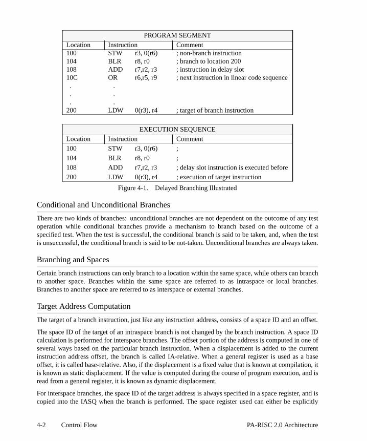
any teste of a the tests taken.
branchranches.
offset.
pace ID one of current a basetion, it, and is
er, and isplicitly
Conditional and Unconditional Branches
There are two kinds of branches: unconditional branches are not dependent on the outcome of operation while conditional branches provide a mechanism to branch based on the outcomspecified test. When the test is successful, the conditional branch is said to be taken, and, whenis unsuccessful, the conditional branch is said to be not-taken. Unconditional branches are alway
Branching and Spaces
Certain branch instructions can only branch to a location within the same space, while others canto another space. Branches within the same space are referred to as intraspace or local bBranches to another space are referred to as interspace or external branches.
Target Address Computation
The target of a branch instruction, just like any instruction address, consists of a space ID and an
The space ID of the target of an intraspace branch is not changed by the branch instruction. A scalculation is performed for interspace branches. The offset portion of the address is computed inseveral ways based on the particular branch instruction. When a displacement is added to theinstruction address offset, the branch is called IA-relative. When a general register is used asoffset, it is called base-relative. Also, if the displacement is a fixed value that is known at compilais known as static displacement. If the value is computed during the course of program executionread from a general register, it is known as dynamic displacement.
For interspace branches, the space ID of the target address is always specified in a space registcopied into the IASQ when the branch is performed. The space register used can either be ex
PROGRAM SEGMENT
Location Instruction Comment100 STW r3, 0(r6) ; non-branch instruction104 BLR r8, r0 ; branch to location 200108 ADD r7,r2, r3 ; instruction in delay slot10C OR r6,r5, r9 ; next instruction in linear code sequence . . . . . .200 LDW 0(r3), r4 ; target of branch instruction
EXECUTION SEQUENCE
Location Instruction Comment
100 STW r3, 0(r6) ;
104 BLR r8, r0 ;
108 ADD r7,r2, r3 ; delay slot instruction is executed before
200 LDW 0(r3), r4 ; execution of target instruction
Figure 4-1. Delayed Branching Illustrated
4-2 Control Flow PA-RISC 2.0 Architecture

xplicitment tonote thewordnches,htmostranches
e target,t, a 12-uction in ther base-
left by
ion byd if it istargetructiong the
returny thepoint
the
aspacexplicit of thelways
ds ons.
ardlifiedn is
specified in the instruction or implicitly specified by the upper 2 bits of the base register. For einterspace branches, the offset of the target is computed by adding a 17-bit signed word displacethe base register specified in a general register. The two rightmost bits in the base register denew privilege level and are ignored during the offset computation. Also, the 17-bit signed displacement is shifted left by two before adding to the base register. For implicit interspace brathe offset of the target is directly specified by the base register with no displacement. The two rigbits in the base register denote the new privilege level and are not part of the offset. Interspace bare always base-relative.
In the case of intraspace branches, the space ID is not changed by the branch. The offset of thhowever, can be computed in one of three ways. For IA-relative branches with static displacemenbit, 17-bit, or 22-bit signed word displacement is shifted left by two and added to the current instraddress offset plus eight. For IA-relative branches with dynamic displacement, the value specifiedindex register is shifted left by three and added to current instruction address offset plus eight. Forelative branches with dynamic displacement, the value specified in the index register is shiftedthree and added to the value in the specified base register.
It should be noted that for IA-relative branches, the target is computed from the current instructadding a displacement or an index value. Since the instruction in the delay slot must be executenot nullified, an additional value of eight is added in the offset computation to arrive at the correctly. This is done to ensure that a branch with a displacement of zero will branch to the instfollowing the delayed instruction. Also, this helps users build case tables immediately followindelay slot instruction.
Linkage
Linkage is provided in certain branch instructions to allow a return path for procedure calls. The point is four bytes after the following instruction. Since the execution of all branches is followed bexecution of the instruction in the delay slot (or null if nullified), it should be noted that the return is always specified as four bytes after the following instruction and not eight bytes after theBRANCHinstruction. When the following instruction is not spatially sequential, then four bytes afterfollowing instruction is not the same as eight bytes after theBRANCH instruction.
The linkage mechanism is available for both intraspace and interspace branches. For intrbranches, the offset of the return point is saved in the specified target register GR t. For einterspace branches, the offset of the return point is always saved in GR 31, and the space IDreturn point is saved in SR 0. For implicit interspace branches, the offset of the return point is asaved in GR 2.
Conditional Branching and Nullification
When nullification is specified by a conditional branch instruction, the effect of nullification depenthe direction of the branch. This maximizes useful work done during loops and “if-then” construct
For a backward conditional branch, the following instruction is nullified only when the backwconditional branch is not taken. For forward conditional branches, the following instruction is nulonly when the forward conditional branch is taken. For unconditional branches, if nullificatiospecified, the following instruction is nullified independent of the direction of branch.
4-3PA-RISC 2.0 Architecture Control Flow

a paire back
pacequeuescome the
he wordet. For backpace ID.es are
ay slottion, I3,r I3. Thebe at of its
therrentlycified
, and
Branching and Address Queues
The concept of delayed branching makes it necessary to maintain the instruction address (IA) inof two element queues. The front elements point to the currently executing instruction and thelements point to the following instruction that will be executed. The term next refers to the SIdentifier and the offset of the next instruction address, which will enter the back elements of the when the queues are updated. The queues are said to be updated when the back elements befront and next become the back elements.
For taken branches, the IA queues get updated with the address of the branch target. Both toffset and the privilege level are updated. IAOQ_Next receives the value of the branch target offsnot-taken branches, IAOQ_Next gets IAOQ_Back + 4. The privilege level is obtained from theelement of the queue. For interspace branches, IASQ_Next gets the value of the branch target SOtherwise, IASQ_Next receives the content of IASQ_Back. Figure 4-2 shows how the IA queuupdated, using a pseudo-code representation.
Figure 4-2. Updating Instruction Address Queues
Consider the situation shown in Figure 4-3; a taken branch instruction, I2, is executed in the delof a preceding taken branch, I1. When this occurs, the first branch I1 schedules its target instructo execute after I2, and the second branch, I2, schedules its target instruction, I4, to execute aftenet effect is the out-of-line execution of I3, followed by the execution of I4. Also, if I3 were to taken branch, its target, I5, would execute after I4, and I4 would also have been executed ouspatial context.
Note that if nullification is specified in the instruction currently executing, the nullification affectsinstruction to be executed next, regardless of whether that instruction immediately follows the cuexecuting instruction in the linear code sequence. For example, if the instruction, I2, spenullification of the next instruction, then I3 would have no effect except that the PSW X-bit, N-bitB-bit would be set to 0.
Instruction Address Offset Queue (IAOQ)
IAOQ_Front ← IAOQ_Back;IAOQ_Back ← IAOQ_Next;if (taken branch)
IAOQ_Next ← Branch target offset;else
IAOQ_Next ← IAOQ_Back + 4;
Instruction Address Space Queue (IASQ)
IASQ_Front ← IASQ_Back;IASQ_Back ← IASQ_Next;if (interspace branch)
IASQ_Next ← Branch target Space ID;else
IASQ_Next ← IASQ_Back;
4-4 Control Flow PA-RISC 2.0 Architecture

. Sincedress,
targetivilegepace orlower, thathich
target
anect.
iveheed)
,e
Privilege Level Changes
Branch instructions may change the privilege level depending on the type of branch performedprivilege levels are determined by the two rightmost bits in the offset part of the instruction adprivilege level changes are a function of the offset computation.
Unconditional branches can be IA-relative or base-relative. IA-relative branches compute theaddress relative to their own IA value, and since the two rightmost bits are unchanged, the prlevel of the branch instruction and the target are the same. base-relative branches (intrasinterspace) may lower the privilege level if the two rightmost bits in the base register are of a privilege level. TheGATE completer of theBRANCH instruction performs an IA-relative branchhowever, it behaves differently for privilege computation. It can promote the privilege level tospecified by the two rightmost bits of the type field, located in the TLB entry for the page from wtheBRANCH-with-GATE instruction is fetched.
Conditional branch instructions always perform IA-relative branches and the privilege level of the instruction and the branch instruction is the same.
The change of privilege level always takes effect at the target instruction.
Programming NoteSince a branch instruction may be executed in the delay slot of another branch instruction, interesting case arises because of the way the privilege level changes are defined to take eff
Consider the case where a taken IA-relative branch is placed in the delay slot of a base-relatbranch that lowers the privilege level of its target instruction. First, the base-relative brancwill execute and schedule change of privilege level for its target. Then, in the delay slot, thIA-relative branch will execute and it will schedule its target to execute at the same privileglevel as its own. Then, the target of the base-relative branch will execute at the new (demoteprivileged level. The next instruction, however, which is the target of the IA-relative branchwill have the same privilege level as that of the IA-relative branch, and thus will cause thprivilege level to be restored to the original (higher) value as shown in the following:
PROGRAM SEGMENT
Location Instruction Comment
100 STW r7, 0(r8) ; non-branch instruction
104 BV r0(r7) ; branch vectored to 200 and change priv -> 2
108 BLR r4, r0 ; IA-relative branch to location 400
10C ADD r2,r6, r9 ; next instruction in linear code sequence
. .
. .
. .
200 LDW 0(r3), r11 ; target of branch vectored instruction
. .
. .
. .
4-5PA-RISC 2.0 Architecture Control Flow

, and ag. If ther trapilege
chken, the
Traps Associated with Branches
Branch instructions may cause various traps based on the value of PSW bits. If the PSW T-bit is 1branch is taken, a taken branch trap occurs. This trap may be used for the purposes of debugginPSW H-bit is 1, and a branch instruction raises the privilege level, a higher-privilege transfeoccurs. If the PSW L-bit is 1, and a branch instruction lowers the privilege level, a lower-privtransfer trap occurs.
Restrictions in Branching
It is illegal for a BRANCH with GATE instruction to execute in the delay slot of a taken braninstruction. The PSW B-bit ensures that this sequence is not permitted. Whenever a branch is taPSW B-bit is set to 1 and, if the next instruction is aBRANCH with GATE, an illegal instruction trapoccurs.
400 LDW 0(r15), r4 ; target of IA-relative branch instruction
404 STW r4, 0(r18)
EXECUTION SEQUENCE
Location Instruction Comment
100 STW r7, 0(r8) ; priv = 0
104 BV r0(r7) ; priv = 0
108 BLR r4, r0 ; priv = 0
200 LDW 0(r3), r11 ; priv = 2 decreased by branch vectored instr
400 LDW 0(r15), r4 ; priv = 0 changed back by IA-relative branch
404 STW r4, 0(r18) ; priv = 0
PROGRAM SEGMENT
Location Instruction Comment100 STW r7, 0(r8) ; non-branch instruction104 BV r0(r7) ; branch vectored to location 200 I1108 BLR r4, r0 ; IA-relative branch to location 400 I210C ADD r2,r6, r9 ; next instruction in linear code sequence . . . . . .200 LDW 0(r3), r11 ; target of branch vectored instruction I3204 ADD r11,r12, r14 ; . .
PROGRAM SEGMENT
4-6 Control Flow PA-RISC 2.0 Architecture
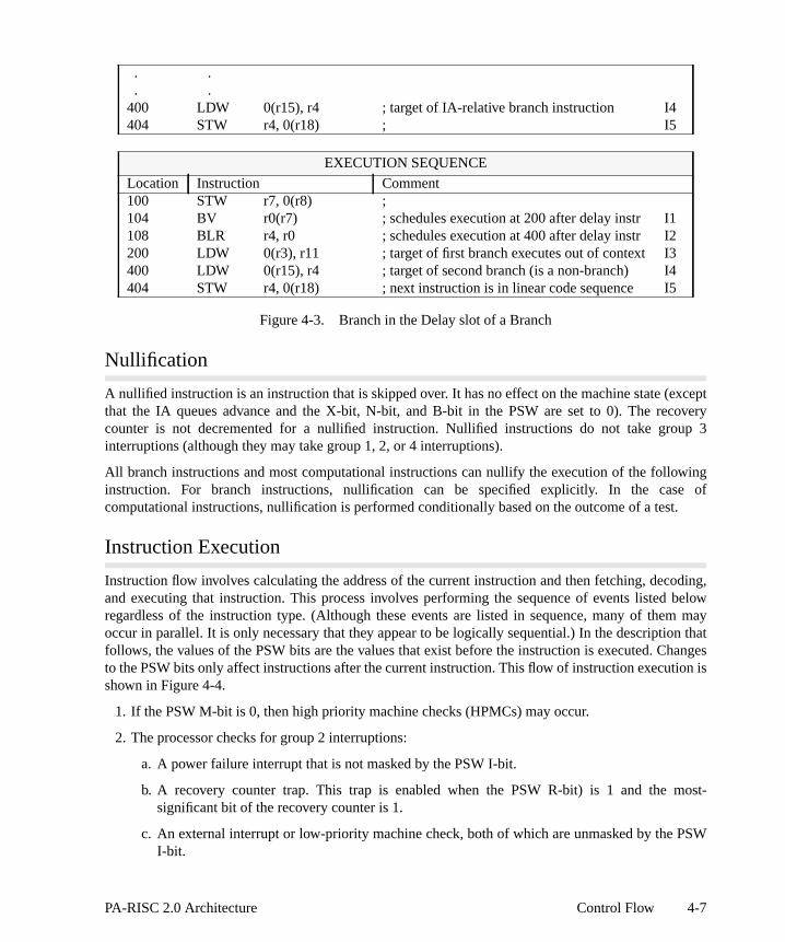
exceptcoveryup 3
wing of
t.
oding, belowm may
on thathangesion is
most-
PSW
Figure 4-3. Branch in the Delay slot of a Branch
Nullification
A nullified instruction is an instruction that is skipped over. It has no effect on the machine state (that the IA queues advance and the X-bit, N-bit, and B-bit in the PSW are set to 0). The recounter is not decremented for a nullified instruction. Nullified instructions do not take grointerruptions (although they may take group 1, 2, or 4 interruptions).
All branch instructions and most computational instructions can nullify the execution of the folloinstruction. For branch instructions, nullification can be specified explicitly. In the casecomputational instructions, nullification is performed conditionally based on the outcome of a tes
Instruction Execution
Instruction flow involves calculating the address of the current instruction and then fetching, decand executing that instruction. This process involves performing the sequence of events listedregardless of the instruction type. (Although these events are listed in sequence, many of theoccur in parallel. It is only necessary that they appear to be logically sequential.) In the descriptifollows, the values of the PSW bits are the values that exist before the instruction is executed. Cto the PSW bits only affect instructions after the current instruction. This flow of instruction executshown in Figure 4-4.
1. If the PSW M-bit is 0, then high priority machine checks (HPMCs) may occur.
2. The processor checks for group 2 interruptions:
a. A power failure interrupt that is not masked by the PSW I-bit.
b. A recovery counter trap. This trap is enabled when the PSW R-bit) is 1 and the significant bit of the recovery counter is 1.
c. An external interrupt or low-priority machine check, both of which are unmasked by the I-bit.
. . . .400 LDW 0(r15), r4 ; target of IA-relative branch instruction I4404 STW r4, 0(r18) ; I5
EXECUTION SEQUENCE
Location Instruction Comment100 STW r7, 0(r8) ;104 BV r0(r7) ; schedules execution at 200 after delay instr I1108 BLR r4, r0 ; schedules execution at 400 after delay instr I2200 LDW 0(r3), r11 ; target of first branch executes out of context I3400 LDW 0(r15), r4 ; target of second branch (is a non-branch) I4404 STW r4, 0(r18) ; next instruction is in linear code sequence I5
4-7PA-RISC 2.0 Architecture Control Flow

t be
d. A performance monitor interrupt that is not masked by the PSW F-bit.
3. Depending on the state of the PSW N-bit, one of two events occur:
a. If the current instruction is nullified (the PSW N-bit is 1), group 3 interruptions must no
Figure 4-4. Interruption Processing
RFI
RFI
YESNO
YESNO
RFI RFI
Note: the solidline represents
the normalexecution path.
Dotted lineboxes describe
softwareactivities.
Fetch currentinstruction, performcurrent instruction,advance IA Queue
and RecoveryCounter, update
PSW.
group 3interruptionpending?
group 4interruptionpending?
group 2interruptionpending?
vector to highest-priority pending
group 4 interruption
process all pendinggroup 4
interruptions
vector to highestpriority pending
group 2 interruption
vector to highest-priority pending
group 3 interruption
back out effect ofcurrent instruction;backup recovery
counter, PSW, andIA queues.
process interruption
process interruption
YESNO
4-8 Control Flow PA-RISC 2.0 Architecture

ith theW X-
hedccursg theion ofa splitf the
r an
on isN-bitdepends
ueue is the
k of theilegeit is set
cuted
n thataken.H-bitilege
T-bit
ludingwhichncludeaffects
fect the
taken. The instruction address queue is advanced and the back of the queue is written wnew front element + 4. The privilege level is the same as the new front element. The PSbit, N-bit, and B-bit are set to 0.
b. If the current instruction is not nullified (the PSW N-bit is 0), then the instruction is fetcusing the front elements of the instruction address (IA) queues. If a group 3 interruption oduring execution, the processor rolls back the effect of the current instruction by restorinbeginning state and takes the interruption. If the PSW C-bit is 1, virtual address translatthe instruction address is performed. The PSW P-bit enables protection checking. On TLB system, the instruction TLB is used for instruction address translation. The fetching ocurrent instruction may result in an instruction TLB miss fault/instruction page fault oinstruction memory protection trap.
The Recovery Counter is decremented if the PSW R-bit is 1. The current instructiexecuted and the PSW X-bit is set to 0. If the next instruction is to be nullified, the PSW is set to 1, and the instruction address queues are updated. The nature of that update on whether the current instruction is a taken branch:
• For a taken branch: the instruction address queues are advanced, the back of the qloaded with the target address including the privilege level which is computed bybranch instruction, and the PSW B-bit is set to 1.
• For a branch that is not taken: the instruction address queues are advanced, the bacinstruction address offset queue is written with the new front element + 4, the privlevel of the back element is set the same as the new front element, and the PSW B-bto 0.
• If the current instruction is aRETURN FROM INTERRUPTION instruction, the IA queuesand the PSW are updated with the new values and the following instruction is exebased on these new values.
4. Group 4 traps are handled after execution is complete. If the new privilege level is lower thaof the just completed instruction and the PSW L-bit was 1, a lower-privilege transfer trap is tIf the new privilege level is higher than that of the just completed instruction and the PSW was 1, a higher-privilege transfer trap is taken. The term “new privilege” level refers to the privlevel at which the following instruction executes.
If neither transfer trap is taken, the instruction just completed is a taken branch, and the PSWwas 1, then a taken branch trap occurs.
Instruction Pipelining
The architecture permits implementations to prefetch up to seven instructions from the cache (incbranch prediction) beyond the instruction currently executing. Instructions may modify resources affect instruction fetch on the machine they are executing on. Instruction fetch resources iprotection identifier registers, the PSW, and TLB entries. When such an event takes place, it instructions that are fetched 8 instructions later (at the latest), or after the nextRETURN FROMINTERRUPTION instruction, whichever occurs first.
Instructions may also modify resources on other processors in a multiprocessor system, which af
4-9PA-RISC 2.0 Architecture Control Flow

of theter they
essors,ompleteoval.
fter the
ove-
is in the
instruction fetch of the target processors. When such an event takes place (the modificationresource is acknowledged), it affects instructions that are fetched, on the target processors, afhave finished executing 8 instructions (at the latest) except as noted below.
When a processor executes an instruction which purges an instruction TLB entry in other procthe target processors must acknowledge completing the purge. The target processors may not ca move-in, which was initiated using the purged translation, after acknowledging the remAcknowledgment of a data TLB purge request from another processor must not be made until apurge has logically been performed.
Modification of code, while discouraged, may be performed using the following protocol:
1. Modify the code in the data cache.
2. Flush the modified code from the data cache.
3. Issue aSYNCHRONIZE CACHES instruction to ensure the flush is completed and subsequent min will observe the memory version.
4. Flush the location of the modified code from the instruction cache.
5. Issue aSYNCHRONIZE CACHES instruction to ensure the flush is completed.
6. Delay at least an additional seven instructions or execute aRETURN FROM INTERRUPTIONinstruction.
In a multiprocessor system, software must ensure that no other processor is executing code thatprocess of being modified.
4-10 Control Flow PA-RISC 2.0 Architecture

controlcessor
errupted
d. Thatised byon.
during
due toystem
s are
rrentd by
cludewithnot Traps
tion.
either
to four
5 Interruptions
Interruptions are anomalies that occur during instruction processing, causing transfer of the flow to an interruption handling routine. In the process, the hardware automatically saves certain prostate. Upon completion of interruption processing, aRETURN FROM INTERRUPTION instruction isexecuted, which restores the saved processor state, and the execution proceeds with the intinstruction.
From the viewpoint of response to interruptions, the processor behaves as if it were not pipelineis, it behaves as if a single instruction is fetched and executed, and any interruption conditions rathat instruction are handled at that time. If there are none, the next instruction is fetched, and so
Interrupt Classes
Faults, traps, interrupts, and checks are the different classes of interruptions that may happeninstruction processing. Definitions of the four classes of interruptions are as follows:
Fault The current instruction requests a legitimate action which cannot be carried out a system problem, such as the absence of a page from main memory. After the sproblem has been corrected, the faulting instruction will execute normally. Faultsynchronous with respect to the instruction stream.
Trap Traps include two sorts of possibilities: either the function requested by the cuinstruction cannot or should not be carried out, or system intervention is desirethe user before or after the instruction is executed. Examples of the first type inarithmetic operations that result in signed overflow and instructions executed insufficient privilege for their intended function. Such instructions are normally re-executed. Examples of the second type include the debugging support traps.are synchronous with respect to the instruction stream.
Interrupt An external entity (for example, an I/O device or the power supply) requires attenInterrupts are asynchronous with respect to the instruction stream.
Check The processor has detected an internal malfunction. Checks can be synchronous or asynchronous with respect to the instruction stream.
All four classes of interruptions are handled in the same way. The interruptions are categorized ingroups based on their priorities:
Group 1: 1 High-priority machine check
Group 2: 2 Power failure interrupt
3 Recovery counter trap
4 External interrupt
5 Low-priority machine check
29 Performance monitor interrupt
5-1PA-RISC 2.0 Architecture Interruptions

whichticularns areeous
plete
nd 3ptions,
The interruption numbers in the above list are the individual vector numbers that determine interruption handler is invoked for each interruption. The group numbers determine when the parinterruption will be processed during the course of instruction execution. The order the interruptiolisted within each group (not the interruption numbers) determines the priority of simultaninterruptions (from highest to lowest).
Interruption Handling
Interruption handling is implemented as a fast context switch (which is much simpler than a comprocess swap). When an interruption occurs, the hardware takes the following actions:
1. The PSW in effect at the time of the interruption is saved in the IPSW. For group 2 ainterruptions, the saved PSW is the value at the beginning of execution. For group 4 interruthe saved PSW is the value after the execution of the instruction.
2. The defined bits in the PSW are set as follows:
W Set to the value of the default width bit.
E Set to the value of the default endian bit.
Group 3: 6 Instruction TLB miss fault/Instruction page fault
7 Instruction memory protection trap
8 Illegal instruction trap
9 Break instruction trap
10 Privileged operation trap
11 Privileged register trap
12 Overflow trap
13 Conditional trap
14 Assist exception trap
15 Data TLB miss fault/Data page fault
16 Non-access instruction TLB miss fault
17 Non-access data TLB miss fault/Non-access data page fault
26 Data memory access rights trap
27 Data memory protection ID trap
28 Unaligned data reference trap
18 Data memory protection trap/Unaligned data reference trap
19 Data memory break trap
20 TLB dirty bit trap
21 Page reference trap
22 Assist emulation trap
Group 4: 23 Higher-privilege transfer trap
24 Lower-privilege transfer trap
25 Taken branch trap
5-2 Interruptions PA-RISC 2.0 Architecture

0.
tep 2
st twog from havequeuesn, theues may
isterss are
eful in9). Ifce and
eter
-bit was.
toringy thisptioned on
al
savedcessingr othertion is
M Set to 1 if the interruption is a high-priority machine check; otherwise, set to
all other bits Set to 0 (interrupts are masked, absolute accesses are enabled, etc.).
3. IA information in the IIA queues is frozen (as a result of setting the PSW Q-bit to 0 in sabove).
In order to enable restarting of instructions in the presence of delayed branching, at leaaddresses must be saved, pointing to the next two instructions to be executed after returninthe interruption. The hardware, therefore, maintains IIA Space and IIA Offset queues, whichtwo elements and contain the addresses and privilege levels of these instructions. The IIA are kept up-to-date whenever the Q-bit in the PSW is 1. When an interruption is takeaddresses of the pending instructions are preserved in the queues. The elements of the quebe obtained by reading the IIASQ and IIAOQ registers (CRs 17 and 18, respectively).
4. The current privilege level is set to the highest privilege level (zero).
5. Information about the interrupting instruction is saved in the Interruption Parameter Reg(IPRs) if the PSW Q-bit was 1 at the time of the interruption. If the PSW Q-bit was 0, the IPRunchanged. If the details of an instruction associated with the interruption are potentially usprocessing it, the instruction is loaded into the Interruption Instruction Register (IIR or CR 1there is an address associated with the interruption, it is loaded into the Interruption SpaInterruption Offset registers (ISR or CR 20, and IOR or CR 21). See “Interruption ParamRegisters (IPRs)” on page 2-15 for a description of the format of these registers.
6. General registers 1, 8, 9, 16, 17, 24, and 25 are copied to the shadow registers if the PSW Q1 at the time of the interruption. If the PSW Q-bit was 0, the shadow registers are unchanged
7. Execution begins at the address given by:
Interruption Vector Address + (32 * interruption_number)
Interruption_number is the unique integer value assigned to that particular interruption. Vecis accomplished by performing an indexed branch into the Interruption Vector Table indexed binteger. The Interruption Vector Table contains the first eight instructions of each of the interruhandling routines. The value in the Interruption Vector Address register (CR 14) must be aligna 2 Kbyte boundary.
Programming NoteIt is the responsibility of interruption handlers to unmask external interrupts (by setting thePSW I-bit to 1) as soon as possible, so as to minimize the worst-case latency of externinterrupts.
Instruction Recoverability
When execution of instructions is interrupted, the minimal processor state that is required to beand restored is that necessary to correctly continue execution of the instruction stream after proof the interruption. Processor state is defined to include any register contents, PSW bits, oinformation that may affect the operation performed by an instruction. For example, if an interrup
5-3PA-RISC 2.0 Architecture Interruptions

ister
ed. Ituption
le to
s, andtate in
enerallys been
s within
. Theyre than
ltiple severalus with
before
eitherout to
xternalents of
es. Ifare re- be set
taken immediately before anADD instruction, its source registers must be restored, but its target regneed not be (unless it is also one of the source registers).
Masking and Nesting of Interruptions
Disabling an interruption prevents it from occurring. The interruption does not wait until re-enablis not kept pending. Masking an interruption does not prevent the recognition of a pending interrcondition, but delays the occurrence of the interruption until it is “unmasked”.
The IA state is collected in the IIA queues only while the PSW Q-bit is 1; it is usually not possibresume execution after an interruption which is taken while the PSW Q-bit is 0.
The machine state is saved in registers rather than memory when an interruption occurinterruption handlers must leave interruptions disabled until they have saved the machine smemory. Once the machine state is saved, nested interrupts can be allowed.
Since it is desirable to catch hardware faults as soon as possible, interruption handlers should gnot mask high-priority machine checks. If a machine check occurs before the machine state hasaved, the interrupted process may need to be aborted. The occurrence of traps and faultinterruption handlers can be avoided by careful writing of the handlers.
Interruption Priorities
High-priority machine checks (which belong to Group 1) may occur and be processed at any timemay be synchronous or asynchronous with instruction processing, may be associated with moone instruction, and their precise meaning and processing is implementation dependent.
All interruptions other than high-priority machine checks are taken between instructions. Musimultaneous interruptions may occur because a number of instructions are capable of raisingsynchronous interruptions simultaneously, and because certain interruptions are asynchronorespect to the instruction stream.
Group 2 interruptions occur asynchronously with respect to the instruction stream.
Group 3 interruptions are synchronous with respect to the instruction stream and are signalledcompletion of the instruction that produces them.
Group 4 interruptions are synchronous with respect to the instruction stream and are signalledafter completion of the instruction that causes them, or when a change in privilege level is abhappen.
Relative priorities are not assigned to the 64 external interrupts by the hardware. When multiple einterrupts occur simultaneously, software may select their order of service, based on the contEIR.
Return from Interruption
TheRETURN FROM INTERRUPTION instruction restores the PSW and the instruction address queuthe old PSW stored in IPSW (CR 22) has interruptions enabled (or unmasked), interruptions enabled before execution of the first of the continuation instructions. The PSW Q-bit may reliably
5-4 Interruptions PA-RISC 2.0 Architecture

a
the
0
)
nd at
RISC
ntinue
of thelt the
to 1 only by aRETURN FROM INTERRUPTION instruction. An attempt to set the PSW Q-bit to 1 withSET SYSTEM MASK or MOVE TO SYSTEM MASK instruction is an undefined operation.
Adding the “,R” (restore) completer to theRETURN FROM INTERRUPTIONinstruction does everythingthat a normalRETURN FROM INTERRUPTION instruction does, and in addition causes the values inshadow registers to be copied to GRs 1, 8, 9, 16, 17, 24, and 25. Execution of aRETURN FROMINTERRUPTION with the “,R” completer leaves the contents of the shadow registers undefined.
Executing aRETURN FROM INTERRUPTION instruction with the PSW Q-bit 0 and the IPSW Q-bit leaves the IPRs unchanged.
Programming NoteOnly those interruptions which are themselves uninterruptible (they leave the PSW Q-bit 0may return from the interruption using theRFI,R instruction. Interruption handling code whichis interruptible (they set the PSW Q-bit to 1) must return from the interruption using theRFIinstruction.
Fast interruption handling is achieved using shadow registers, since GRs 1, 8, 9, 16, 17, 24, a25 are copied to the shadow registers on interruptions. In this example, it is assumed thatmost seven general registers need to be used in the interruption handling routine.
Interruption Descriptions
The sections that follow provide descriptions of each of the interrupts defined in the PA-architecture.
Group 1 Interruptions
High-priority Machine Check (1)
Cause: A hardware error has been detected that must be handled before processing can co
Parameters: Implementation dependent
IIA Queue: Front – Implementation dependentBack – Implementation dependent
Notes: The actions taken when a hardware error is detected depend on the seriousnesserror. Damage extensive enough to prevent proper execution of instructions will ha
Using RFI Using RFI,R
interrupt interrupt
save GRs <no save>
[process interrupt] [process interrupt]
restore GRs <no restore>
RFI RFI,R
5-5PA-RISC 2.0 Architecture Interruptions

magetes a
to 1,uses ofs of
nd to
equal
nable 23).
value the bit 5f the, an
machine and generate an external indication of the occurrence of the check. Dawhich allows a subset of the instructions to execute (e.g., inoperative TLB) generahigh-priority machine check interruption. This is maskable by setting the PSW M-bit so that machine checks within the machine check handler can be prevented. The cahigh-priority machine checks are implementation dependent, as is the meancontrolling their reporting.
Group 2 Interruptions
Power Failure Interrupt (2)
Cause: The machine is about to lose power
Parameters: none
IIA Queue: Front – Address of the instruction to be executed at the time of the interruptionBack – Address of the following instruction
Notes: This interruption is masked and kept pending when the PSW I-bit is 0.
Recovery Counter Trap (3)
Cause: Bit 0 of the recovery counter is 1 and the PSW R-bit is 1
Parameters: none
IIA Queue: Front – Address of the instruction to be executed at the time of the interruptionBack – Address of the following instruction
Notes: The recovery counter can be used to log interruptions during normal operation asimulate interruptions during recovery from a fault.
External Interrupt (4)
Cause: A module writes to the processor’s IO_EIR register, or the interval timer compares to its associated comparison register
Parameters: none
IIA Queue: Front – Address of the instruction to be executed at the time of the interruptionBack – Address of the following instruction
Notes: Each external interrupt level has associated with it one bit in the External Interrupt EMask Register (CR 15) and one bit in the External Interrupt Request Register (CRWhen a module writes into the EIR register, the bit position corresponding to the written is set to 1. If the default width bit is 1, the bit to set directly corresponds tovalue; if 0, the bit to set is the value + 32. For example if the value 5 is written, thenof the EIR register is set to 1 if the default width bit is 1, and bit 37 of the EIR is set idefault width bit is 0. If the corresponding bit in CR 15 is 1 and the PSW I-bit is 1external interrupt is taken; otherwise, the interrupt is masked, and is kept pending.
Interrupt handling software sets bits in the EIR to 0 by executing aMOVE TO CONTROL
5-6 Interruptions PA-RISC 2.0 Architecture

e to
ediate
t thatchinet is 0.means
essor
TLBslation
or and the
REGISTER instruction with the appropriate mask.
If multiple sources can set the same interrupt, it is the responsibility of softwarcorrectly respond to all of the interrupting sources.
Low-priority Machine Check (5)
Cause: A hardware error has been detected which is recoverable and does not require immhandling
Parameters: Implementation dependent
IIA Queue: Front – Address of the instruction to be executed at the time of the interruptionBack – Address of the following instruction
Notes: Errors which have been detected and recovered from by hardware to the poinoperation can continue in a degraded fashion are reported via the low-priority macheck interruption. This interruption is masked and kept pending when the PSW I-biThe causes of low-priority machine checks are implementation dependent, as is the of controlling their reporting.
Performance Monitor Interrupt (29)
Cause: An implementation-dependent event related to the performance monitor coprocrequires software intervention
Parameters: Implementation dependent
IIA Queue: Front – Address of the instruction to be executed at the time of the interruptionBack – Address of the following instruction
Notes: This interruption is masked and kept pending when the PSW F-bit is 0.
Group 3 Interruptions
Instruction Tlb Miss Fault/instruction Page Fault (6)
Cause: The instruction TLB entry needed by instruction fetch is absent, and if instruction misses are handled by hardware, the hardware miss handler could not find the tranin the Page Table
Parameters: none
IIA Queue: Front – Address of the instruction causing the faultBack – Address of the following instruction
Notes: Only if an instruction is to be executed can an instruction TLB miss fault occur.
Instruction Memory Protection Trap (7)
Cause: Instruction address translation is enabled and the access rights check fails finstruction fetch or instruction address translation is enabled, the PSW P-bit is 1, anprotection identifier checks fails for an instruction fetch
5-7PA-RISC 2.0 Architecture Interruptions

es arep). On
most
ileged
Parameters: none
IIA Queue: Front – Address of the instruction causing the trapBack – Address of the following instruction
Notes: This interruption does not occur for absolute accesses.
Illegal Instruction Trap (8)
Cause: An attempt is being made to execute an illegal instruction or to execute aBRANCH withGATE instruction with the PSW B-bit equal to 1
Parameters: IIR – The illegal instruction causing the trap
IIA Queue: Front – Address of the instruction causing the trapBack – Address of the following instruction
Notes: Illegal instructions are the unassigned major opcodes. Unassigned sub-opcodundefined operations (undefined sub-opcodes may cause the illegal instruction trasome implementations,DIAGNOSE may be an illegal instruction.
Break Instruction Trap (9)
Cause: An attempt is made to execute aBREAK instruction
Parameters: IIR – TheBREAK instruction causing the trap
IIA Queue: Front – Address of the instruction causing the trapBack – Address of the following instruction
Privileged Operation Trap (10)
Cause: An attempt is being made to execute a privileged instruction without being at the privileged level (priv= 0)
Parameters: IIR – The privileged instruction causing the trap
IIA Queue: Front – Address of the instruction causing the trapBack – Address of the following instruction
Notes: The list of privileged instructions is:DIAG, IDTLBT, IITLBT, LCI, LDDA, LDWA, LPA,MTSM, PDTLB, PDTLBE, PITLB, PITLBE, RFI, RSM, SSM, STDA, STWA.
Privileged Register Trap (11)
Cause: An attempt is being made to write to a privileged space register or access a privcontrol register without being at the most privileged level (priv= 0)
Parameters: IIR – The instruction causing the trap
IIA Queue: Front – Address of the instruction causing the trapBack – Address of the following instruction
Notes: This interruption may be caused by theMOVE TO SPACE REGISTER, MOVE TO CONTROLREGISTER, or MOVE FROM CONTROL REGISTER instructions.
5-8 Interruptions PA-RISC 2.0 Architecture

ation.
en ang the
essor.
ction isr could
miss
Overflow Trap (12)
Cause: A signed overflow is detected in an instruction which traps on overflow
Parameters: IIR – The instruction causing the trap
IIA Queue: Front – Address of the instruction causing the trapBack – Address of the following instruction
Conditional Trap (13)
Cause: The condition succeeds in an instruction which traps on condition
Parameters: IIR – The instruction causing the trap
IIA Queue: Front – Address of the instruction causing the trapBack – Address of the following instruction
Assist Exception Trap (14)
Cause: A coprocessor or special function unit has detected an exceptional condition or operAn exceptional operation may include unimplemented operations or operands.
Parameters: IIR – For immediate traps, the SFU or coprocessor instruction that was executing whexception is reported with a trap. It may or may not be related to the condition causinexception. For delayed traps, any instruction corresponding to the SFU or coprocSee “Interruptions and Exceptions” on page 10-4.
IIA Queue: Front – Address of the instruction causing the trapBack – Address of the following instruction
Data Tlb Miss Fault/data Page Fault (15)
Cause: The data TLB entry needed by operand access of a load, store, or semaphore instruabsent, and if data TLB misses are handled by hardware, the hardware miss handlenot find the translation in the Page Table
Parameters: ISR – space identifier of data addressIOR – offset of data addressIIR – The instruction causing the fault
IIA Queue: Front – Address of the instruction causing the faultBack – Address of the following instruction
Notes: This interruption does not occur for absolute accesses.
Non-access Instruction Tlb Miss Fault (16)
Cause: The instruction TLB entry needed for the target of aFLUSH INSTRUCTION CACHEinstruction is absent, and if TLB misses are handled by hardware, the hardwarehandler could not find the translation in the Page Table
Parameters: ISR – space identifier of virtual address to be flushedIOR – offset of virtual address to be flushed
5-9PA-RISC 2.0 Architecture Interruptions

faultccur
, the
e faultccur
perand
check purge
IIR – The instruction causing the fault
IIA Queue: Front – Address of the instruction causing the faultBack – Address of the following instruction
Notes: This interruption source is distinguished from other TLB misses because a pageshould not result in reading the faulting page from disk. This interruption does not ofor absolute accesses.
Non-access Data Tlb Miss Fault/non-access Data Page Fault (17)
Cause: The data TLB entry needed by aLOAD PHYSICAL ADDRESS, PROBE ACCESS, PROBEACCESS IMMEDIATE, FLUSH INSTRUCTION CACHE, PURGE DATA CACHE, or aFLUSHDATA CACHE instruction is not present, and if TLB misses are handled by hardwarehardware miss handler could not find the translation in the Page Table
Parameters: ISR – space identifier of virtual addressIOR – offset of virtual addressIIR – The instruction causing the fault
IIA Queue: Front – Address of the instruction causing the faultBack – Address of the following instruction
Notes: These interruption sources are distinguished from other TLB misses because a pagshould not result in reading the faulting page from disk. This interruption does not ofor absolute accesses.
Data Memory Access Rights Trap (26)
Cause: Data address translation is enabled, and an access rights check fails on an oreference for a load, store, or semaphore instruction, or a cache purge operation
Parameters: ISR – space identifier of the virtual addressIOR – offset of the virtual addressIIR – The instruction causing the trap
IIA Queue: Front – Address of the instruction causing the trapBack – Address of the following instruction
Notes: This interruption does not occur for absolute accesses.
Data Memory Protection Id Trap (27)
Cause: Data address translation is enabled, the PSW P-bit is 1, and a protection identifierfails on an operand reference for a load, store, or semaphore instruction, or a cacheoperation
Parameters: ISR – space identifier of the virtual addressIOR – offset of the virtual addressIIR – The instruction causing the trap
IIA Queue: Front – Address of the instruction causing the trapBack – Address of the following instruction
5-10 Interruptions PA-RISC 2.0 Architecture
to an
aphore andligned
entifier cache
s withaphore
moryith the (16
PA-and 28
bit 1 in
Notes: This interruption does not occur for absolute accesses.
Unaligned Data Reference Trap (28)
Cause: Data address translation is enabled, and a load or store instruction is attemptedunaligned address
Parameters: ISR – space identifier of the virtual addressIOR – offset of the virtual addressIIR – The instruction causing the trap
IIA Queue: Front – Address of the instruction causing the trapBack – Address of the following instruction
Notes: Unaligned data reference traps are not detected for absolute accesses or seminstructions – they are undefined operations. Only unaligned virtual memory loadsstores (including coprocessor loads and stores) are defined to terminate with the unadata reference trap.
Data Memory Protection Trap/unaligned Data Reference Trap (18)
Cause: Data address translation is enabled, and an access rights check or a protection idcheck fails on an operand reference for a load, store, or semaphore instruction, or apurge operation; a load or store instruction is attempted to an unaligned addresvirtual address translation enabled (unaligned absolute references and seminstructions are undefined operations)
Parameters: ISR – space identifier of the virtual addressIOR – offset of the virtual addressIIR – The instruction causing the trap
IIA Queue: Front – Address of the instruction causing the trapBack – Address of the following instruction
Notes: This interruption does not occur for absolute accesses. Only unaligned virtual meloads and stores (including coprocessor loads and stores) are defined to terminate wdata memory protection trap. Execution of a semaphore instruction with unalignedbyte boundaries) addresses is an undefined operation.
This trap is retained for compatibility with the earlier revisions of the architecture. InRISC 1.1 (Second Edition) and later revisions, processors must use traps 26, 27, which provide equivalent functionality.
Data Memory Break Trap (19)
Cause: Store and semaphore instructions or cache purge operations to a page with the B-the data TLB entry
Parameters: ISR – space identifier of the virtual addressIOR – offset of the virtual addressIIR – The instruction causing the trap
5-11PA-RISC 2.0 Architecture Interruptions

lute
. This
ndingctiongister
IIA Queue: Front – Address of the instruction causing the trapBack – Address of the following instruction
Notes: This trap is disabled if the PSW X-bit is 1. This interruption does not occur for absoaccesses.
Tlb Dirty Bit Trap (20)
Cause: Store and semaphore instructions to a page with the D-bit 0 in the data TLB entry
Parameters: ISR – space identifier of the data addressIOR – offset of the data addressIIR – The instruction causing the trap
IIA Queue: Front – Address of the instruction causing the trapBack – Address of the following instruction
Notes: Software is invoked to update the dirty bit in the data TLB entry and the Page Tableinterruption does not occur for absolute accesses.
Page Reference Trap (21)
Cause: Load, store,and semaphoreinstructions to a page with the T-bit 1 in its data TLB entry
Parameters: ISR – space identifier of the virtual addressIOR – offset of the virtual addressIIR – The instruction causing the trap
IIA Queue: Front – Address of the instruction causing the trapBack – Address of the following instruction
Notes: This interruption does not occur for absolute accesses.
Assist Emulation Trap (22)
Cause: An attempt is being made to execute an SFU instruction for an SFU whose correspobit in the SFU Configuration Register (SCR) is 0 or to execute a coprocessor instrufor a coprocessor whose corresponding bit in the Coprocessor Configuration Re(CCR) is 0
Parameters: ISR – space identifier of the data addressIOR – offset of the data addressIIR – The instruction causing the trap
IIA Queue: Front – Address of the instruction causing the trapBack – Address of the following instruction
Notes: ISR and IOR contain valid data only if the instruction is a coprocessor load or store.
5-12 Interruptions PA-RISC 2.0 Architecture

just
just
ss of is thed, this
Group 4 Interruptions
Higher-privilege Transfer Trap (23)
Cause: An instruction is about to be executed at a higher privilege level than the instructioncompleted and the PSW H-bit is 1
Parameters: none
IIA Queue: Front – Address of the instruction with the higher privilege levelBack – Address of the following instruction
Lower-privilege Transfer Trap (24)
Cause: An instruction is about to be executed at a lower privilege level than the instructioncompleted and the PSW L-bit is 1
Parameters: none
IIA Queue: Front – Address of the instruction with the lower privilege levelBack – Address of the following instruction
Taken Branch Trap (25)
Cause: A taken branch was executed, and the PSW T-bit is 1
Parameters: none
IIA Queue: Front – Address of the instruction to be executed after the branchBack – Address of the branch target
Notes: This interruption occurs after the execution of the branch instruction, and the addrethe branch instruction itself is not available. The address at the front of the IIA queueaddress of the instruction to be executed next. If the branch has nullification specifieis the address of the nullified instruction (the PSW N-bit is 1 in this case).
5-13PA-RISC 2.0 Architecture Interruptions

5-14 Interruptions PA-RISC 2.0 Architecture

d into
cusses, theirn detailn, therrative
cases,
isters,ters, ifder ofitional
ctionspecify
6 Instruction Set Overview
This chapter provides an overview of the PA-RISC instruction set. The instructions can be dividethe following functional groups:
• Computation instructions.
• Multimedia instructions.
• Memory Reference instructions.
• Long Immediate instructions.
• Branch instructions.
• System Control instructions.
• Assist instructions.
The instruction set consists of defined, undefined, illegal, and null instructions. This chapter disthe concepts of undefined and null instructions and includes descriptions of the conditionscompleters, and the notation used in the instruction descriptions. Each instruction is described iin Chapter 7, “Instruction Descriptions”. Each description includes the full name of the instructioassembly language mnemonic and syntax format, machine instruction format, purpose, a nadescription, an operational description, exceptions, and notes concerning usage. In someprogramming notes are included for additional guidance to programmers.
Instructions are always 32 bits in width. A 6-bit major opcode is always the first field. Source regif specified, are often the next two 5-bit fields and are always in the same place. Target regisspecified, are not fixed in any particular 5-bit field. Depending on the major opcode, the remainthe instruction word is divided into fields that specify immediate values, space registers, addopcode extensions, conditions, and nullification.
Computation Instructions
Computation instructions are comprised of the arithmetic, logical, shift, extract, and deposit instruwhich operate on the general registers. The two 5-bit fields following the 6-bit opcode field can sthe following combinations:
1. Two source registers.
2. A source register and a target register.
3. A source register and a 5-bit immediate.
4. A target register and a 5-bit immediate.
Table 6-1 summarizes the computation instructions that are provided.
6-1PA-RISC 2.0 Architecture Instruction Set Overview

eneraler. The
bits ore fieldte isg the
Theed on
rs anditionalns are
nd thetrap on
-
Table 6-1. Computation Instruction Summary
The three-register arithmetic and logical instructions take two source arguments from two gregisters. These source registers are specified by the two 5-bit fields following the opcode specifirightmost 5-bit field specifies the target register.
Some of the computation instructions have a signed immediate argument which is either five eleven bits in length. The 5-bit immediate is encoded in the second 5-bit field following the opcodand the target specifier in the first 5-bit field following the opcode field. The 11-bit immediaencoded in the rightmost 11-bit field, and the target specifier in the second 5-bit field followinopcode specifier.
Many computation instructions may nullify the instruction following, given the correct conditions.instruction condition completers are used to determine if the instruction following is nullified, basthe contents of the source operands and the operation performed.
Three-Register Arithmetic and Logical Instructions
These instructions perform arithmetic and logical operations between two operands in registestore the result into a register. Each arithmetic/logical instruction also specifies the condoccurrence of either a skip or a trap, based on its opcode and the condition field. Not all optioavailable on every instruction. Only those operations and options considered useful are defined.
Immediate Arithmetic Instructions
The immediate arithmetic instructions operate between a sign-extended 11-bit immediate acontents of a register. The result is placed in a register. Immediate operations may optionally overflow. In addition, immediate adds may trap on a specific condition.
3-Register Arithmetic & Logical Instructions
ADD, SHLADD, SUB,OR, XOR, AND, ANDCM,UADDCM,UXOR,DS, CMPCLR, DCOR
Perform arithmetic and logical operations with two operandsin registers and store the result in a third register.
Immediate Arithmetic Instructions
ADDI, SUBI,CMPICLR
Perform arithmetic operations between a sign-extended immediate and the contents of a register. The result is placed in aregister.
Shift Pair, Extract & Deposit Instructions
SHRPD, SHRPW,
EXTRD, EXTRW,
DEPD, DEPDI, DEPW, DEPWI
The shift pair operations allow for a concatenation of two reg-isters followed by a shift of 0 to 63 bit positions.Extract instructions take a field from a source register andinsert it right-justified into the target register.Deposits either set the target to zero or leave it unchanged(merge operation). The deposit instructions then take a right-justified field from a source and deposit it into any portion ofthe target.
6-2 Instruction Set Overview PA-RISC 2.0 Architecture

l
e
et
hese
etic. a the
o force
ll load/
tntations
a
The 11-bit immediate field has the sign bit in the rightmost position, but the other 10 bits are in the usuaorder. The 1-bit opcode extension field determines whether overflow causes a trap.
Shift Pair, Extract, and Deposit Instructions
The shift pair operations allow for a concatenation of two registers followed by a shift of 0 to 63 bitpositions. The rightmost 64 bits are placed in a general register. Depending on the choice of the sourcregisters, this operation allows the user to perform right or left shifts, rotates, bit field extractions whenthe bit field crosses word boundaries, unaligned byte moves, and so on.
Extract instructions take a field from a source register and insert it right-justified into the target register.This field is either zero extended or sign extended. This way, the extract instructions support bothlogical and arithmetic shift operations.
The deposit instructions either set the target to zero or leave it unchanged (merge operation) and thentake a right-justified field from a source and deposit it into any portion of the target. The source can beeither a register or a 5-bit signed immediate value. The 5-bit immediate field has the sign bit in thrightmost position, but the other 4 bits are in the usual order. Deposit instructions support left shifoperations and simple multiplication by powers of two.
Multimedia Instructions
PA-RISC provides efficient support for the most frequent multimedia operations because toperations are assuming greater importance in many applications. Instructions in this category performmultiple parallel operations in a single cycle.
In multimedia workloads, a large portion of the arithmetic can be thought of as saturation arithmThis means that if the result of a calculation would be too large in magnitude to be represented ingiven format, the calculation delivers the largest representable number (as opposed to wrapping toother end of the representable range, as with modular arithmetic). Commonly, this must be implementedby testing each result (twice, for signed results), and performing conditional branches or skips tthe result to a maximum value. The multimedia instructions in PA-RISC perform multiple parallelcomputations, with each of the results being tested and forced to the appropriate value if necessary, in asingle cycle. The result is a sizeable reduction in pathlength and fewer disruptive breaks in control flowin multimedia algorithms.
Re-arrangement instructions provide efficient support for packed pixel data structures in memory, allowalgorithms to make full use of the parallel computation instructions, and enable the use of the fustore bandwidth of the processor in accessing pixel data.
The multimedia instructions are comprised of halfword arithmetic, halfword shift, and rearrangemeninstructions. The instructions operate on 16-bit signed or unsigned numbers. The signed represe
are two's complement numbers in the range –215 to 215–1. Table6-2 summarizes the multimediinstructions provided.
6-3PA-RISC 2.0 Architecture Instruction Set Overview
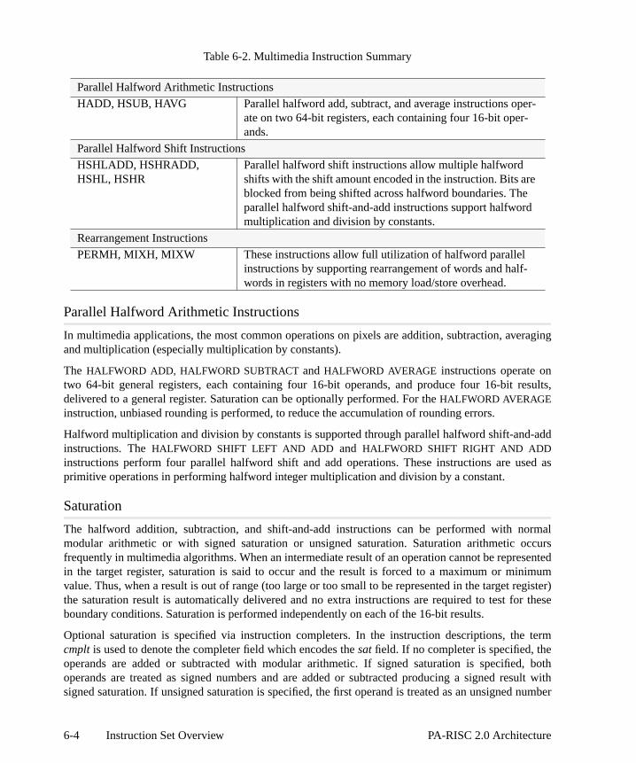
raging
esults,
-add
sed as
ormalccurssentedimumegister)r these
term
, bothsult with number
-
Table 6-2. Multimedia Instruction Summary
Parallel Halfword Arithmetic Instructions
In multimedia applications, the most common operations on pixels are addition, subtraction, aveand multiplication (especially multiplication by constants).
The HALFWORD ADD, HALFWORD SUBTRACTand HALFWORD AVERAGE instructions operate ontwo 64-bit general registers, each containing four 16-bit operands, and produce four 16-bit rdelivered to a general register. Saturation can be optionally performed. For theHALFWORD AVERAGEinstruction, unbiased rounding is performed, to reduce the accumulation of rounding errors.
Halfword multiplication and division by constants is supported through parallel halfword shift-andinstructions. TheHALFWORD SHIFT LEFT AND ADD and HALFWORD SHIFT RIGHT AND ADDinstructions perform four parallel halfword shift and add operations. These instructions are uprimitive operations in performing halfword integer multiplication and division by a constant.
Saturation
The halfword addition, subtraction, and shift-and-add instructions can be performed with nmodular arithmetic or with signed saturation or unsigned saturation. Saturation arithmetic ofrequently in multimedia algorithms. When an intermediate result of an operation cannot be reprein the target register, saturation is said to occur and the result is forced to a maximum or minvalue. Thus, when a result is out of range (too large or too small to be represented in the target rthe saturation result is automatically delivered and no extra instructions are required to test foboundary conditions. Saturation is performed independently on each of the 16-bit results.
Optional saturation is specified via instruction completers. In the instruction descriptions, thecmplt is used to denote the completer field which encodes thesat field. If no completer is specified, theoperands are added or subtracted with modular arithmetic. If signed saturation is specifiedoperands are treated as signed numbers and are added or subtracted producing a signed resigned saturation. If unsigned saturation is specified, the first operand is treated as an unsigned
Parallel Halfword Arithmetic Instructions
HADD, HSUB, HAVG Parallel halfword add, subtract, and average instructions operate on two 64-bit registers, each containing four 16-bit oper-ands.
Parallel Halfword Shift Instructions
HSHLADD, HSHRADD,HSHL, HSHR
Parallel halfword shift instructions allow multiple halfwordshifts with the shift amount encoded in the instruction. Bits areblocked from being shifted across halfword boundaries. Theparallel halfword shift-and-add instructions support halfwordmultiplication and division by constants.
Rearrangement Instructions
PERMH, MIXH, MIXW These instructions allow full utilization of halfword parallelinstructions by supporting rearrangement of words and half-words in registers with no memory load/store overhead.
6-4 Instruction Set Overview PA-RISC 2.0 Architecture

with
innerallyhe
rd in
ll
e
and the second as a signed number. These are added or subtracted producing an unsigned resultunsigned saturation.
The results for maximum saturation and minimum saturation are defined for halfword arithmeticinstructions in the following tables. Signed saturation results are defined in Table6-3 and unsignedsaturation results are defined in Table6-4.
Table 6-3. Signed Saturation Results
Table 6-4. Unsigned Saturation Results
Parallel Halfword Shift Instructions
The halfword shift instructions allow multiple parallel halfword shifts. The shift amount is encodedthe instruction and shifting can be done by any amount, from 0 to 15 bits. These instructions geuse the main shifter, except that they block any bits from being shifted across halfword boundaries. THALFWORD SHIFT LEFT instruction allows multiplication by 2n in a single instruction. TheHALFWORD SHIFT RIGHT instruction allows division by 2n and the shift can be either signed ounsigned. The completer, cmplt, determines which type of shift to perform. The completer is encodethese field of the instruction.
Rearrangement Instructions
The PERMUTE HALFWORDS, MIX HALFWORDS, and MIX WORDS instructions allow full utilization ofthe halfword parallel arithmetic instructions by supporting the rearrangement of words and halfwords inregisters without incurring the overhead of memory load and store instructions. These instructions aowarbitrary permutations and combinations of words and halfwords in a register.
The PERMUTE HALFWORDS instruction can generate any arbitrary combination or permutation of th
Instructions Maximum Saturation Minimum Saturation
HADD, HSUB,HSHRADD
Intermediate result of an operation is
greater than 215–1. The result is forced
to 215–1.
Intermediate result of an operation is
less than –215. The result is forced to
–215.HSHLADD Intermediate result of an operation is
greater than 215–1. The result is forced
to 215–1. In addition, the result is also
forced to 215–1 if the leftmost bit ofthe first operand is 0, and one or moreof the bits shifted out differs from theleftmost bit following the shift.
Intermediate result of an operation is
less than –215. The result is forced to
–215. In addition, the result is also
forced to –215 if the leftmost bit of thefirst operand is 1, and one or more ofthe bits shifted out differs from theleftmost bit following the shift.
Instructions Maximum Saturation Minimum Saturation
HADD, HSUB Intermediate result of an operation is
greater than 216–1. The result is forced
to 216–1.
Intermediate result of an operation isless than 0. The result is forced to 0.
6-5PA-RISC 2.0 Architecture Instruction Set Overview

wo
ondhe
ble 6-5
so canstruction from aer, but“System
nt, andex. Theith datance trap.
resses.
four halfwords from its source operand.
In the MIX HALFWORDS instruction, two halfwords from the first operand are merged with thalfwords from the second operand to produce the result. The completer,cmplt, determines whichhalfwords are selected. The completer is encoded in theea field of the instruction.
In theMIX WORDS instruction, a word from the first operand is merged with a word from the secoperand to produce the result. The completer,cmplt, determines which words are selected. Tcompleter is encoded in theea field of the instruction.
Memory Reference Instructions
Memory reference instructions load values into and store values from the general registers. Tasummarizes the memory reference instructions.
Table 6-5. Memory Reference Instruction Summary
Memory reference instructions work directly between the registers and main memory. They aloperate between the registers and the data cache on implementations so equipped. A load inloads a general register with data from the data cache. A store instruction stores a data valuegeneral register into the data cache. Normally this distinction is transparent to the programmprovisions are made for cache and TLB operations requiring cognizance of the data cache (see Control Instructions” on page 6-17).
The address formation mechanisms supported include: short displacement, long displacemeindexed. It is possible to modify the base value in a general register by the displacement or indrightmost bits of computed addresses are not ignored. Unaligned load and store instructions waddress translation enabled to halfwords, words, or doublewords cause an unaligned data refereSemaphore operations and absolute accesses to unaligned data are undefined operations.
Program synchronization can be done using theLOAD AND CLEAR instructions, which performindivisible semaphore operations. These instructions are required to use 16-byte aligned add
Load/Store
LDB/STB, LDH/STH, LDW/STW,LDD/STD
Load/Store a byte, halfword, word, or doublewordusing a memory address formed using short or longdisplacement or indexed.
Load/Store Absolute
LDWA/STWA,LDDA/STDA
Load/Store a word or doubleword using an absolutememory address formed using short or long displace-ment or indexed.
Load and Clear
LDCW, LDCD Read (load) and lock a word or doubleword sema-phore in main memory.
Store Bytes/DoubleWord Bytes
STBY, STDBY Implement fast byte moves (stores) to unalignedword or doubleword destination.
6-6 Instruction Set Overview PA-RISC 2.0 Architecture
in thee line as
ructionsis 0, or
(when
ace andcription
nfaty
er
aphore,SW X-
When using semaphores to synchronize with I/O, care must be taken in placing other informationsame cache line as the semaphore. Data which is writable, can only be placed in the same cacha semaphore if access to write the data is controlled by the semaphore.
Depending on the state of the PSW D-bit (data address translation bit), most load and store instperform virtual accesses (when the PSW D-bit is 1) or physical accesses (when the PSW D-bit when executingLOAD ABSOLUTE, STORE ABSOLUTE instructions).
The state of the PSW E-bit determines whether the data which is loaded or stored is big endianthe PSW E-bit is 0) or little endian (when the PSW E-bit is 1).
Memory is accessed using the following procedures:
mem_load(space,offset,low,high,hint){
if (PSW[D] == 0)return(phys_mem_load(offset,low,high,hint));
elsereturn(virt_mem_load(space,offset,low,high,hint));
}
mem_store(space,offset,low,high,hint,data){
if (PSW[D] == 0)phys_mem_store(offset,low,high,hint,data);
elsevirt_mem_store(space,offset,low,high,hint,data);
}
There are some restrictions on which instructions can be used for referencing the I/O address spuncacheable memory. See “Operations Defined for I/O Address Space” on page F-12. For a desof memory reference atomicity, see “Atomicity of Storage Accesses” on page G-1.
LOAD OFFSET, LOAD IMMEDIATE LEFT, LOAD PHYSICAL ADDRESS, LOAD COHERENCE INDEX,andLOAD SPACE IDENTIFIER are not memory reference instructions.
Programming NoteExecution may be faster if software avoids dependence on register interlocks. Instructioscheduling to avoid the need for interlocking is recommended. A register interlock will occur ian instruction attempts to use a register which is the target of a previous load instruction thhas not yet completed. This does not restrict the length of the delay a load instruction maincur in a particular system to a single execution cycle; in fact, the delay may be much longfor a cache miss, a TLB miss, or a page fault.
Debugging is facilitated by the data memory break trap. This trap occurs whenever a store, a semor a purge data cache operation is performed to a page with the B-bit 1 in its TLB entry and the Pbit is 0.
6-7PA-RISC 2.0 Architecture Instruction Set Overview

may bea short6-1 onemoryailable
le 6-6
gistering the
ing thes known
Address Formation
Addresses are formed by the combination of a Space ID and an address Offset. Address Offsetsformed as the sum of a base register and any one of the following: a long displacement, displacement (which leaves more instruction bits for other functions), or an index register. Figurepage 6-9 illustrates typical examples of the various methods of forming addresses for the mreference instructions. For detailed illustrations of address calculations for each of the avaddressing methods refer to “Memory Reference Instruction Address Formation” on page H-1.
Not all address formation methods are available with every memory reference instruction. Tabsummarizes the address formation methods and the instructions where each is available.
Table 6-6. Address Formation Options for Memory Reference Instructions
Base Register Modification
All of the address formation methods provide the option of modifying the contents of the Base Reeither before or after the address calculation is performed. The address can be formed by uscontents of Base Register before it is modified (sometimes known as post-increment) or by uscontents of the Base Register after it has been modified by the displacement or index (sometimeas pre-increment.)
Instructions
IndexedShort
DisplacementLong
Displacement
BaseRegister
Modification
LDD, LDW, LDH, LDB X X X XSTD, STW, STH, STB X X XLDDA, LDWA, LDCD, LDCW X X XSTDA, STWA, STBY, STDBY X X
6-8 Instruction Set Overview PA-RISC 2.0 Architecture

without
, storeol hints
Cache Control
Some memory reference instruction formats contain a 2-bit cache control field,cc, which provides ahint to the processor on how to resolve cache coherence. The processor may disregard the hintcompromising system integrity, but performance may be enhanced by following the hint.
There are three different categories of cache control hints: load instruction cache control hintsinstruction cache control hints, and semaphore instruction cache control hints. The cache contrare specified by thecc completer to the instruction and encoded in thecc field of the instruction.
Figure 6-1. Example Address Formation for Memory Reference Instructions
Offset
General Registers0
Base
Offset
64
31
64
64
General Registers0
Base64
31
64
64
Index
Indexed Address Formation
0
31
Base64
+
64
64
Displacement
Low SignExtend
General Registers
Offset
Displacement Address Formation
left
Indexed with Post-modify
General Registers0
Base
Shifted
Offset
64
31
Indexshift
64
64
Index 0-3
Displacement
Low SignExtend
Displacement with Pre-modify
Space IDSpace ID
Space ID Space ID
6-9PA-RISC 2.0 Architecture Instruction Set Overview
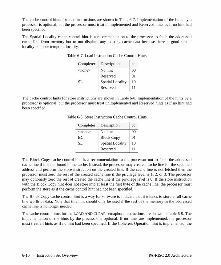
s by ahint had
ressed spatial
s by ahint had
ressedpecifiedhen theocessoructionr must
cacheressed
hecessored, the
The cache control hints for load instructions are shown in Table 6-7. Implementation of the hintprocessor is optional, but the processor must treat unimplemented and Reserved hints as if no been specified.
The Spatial Locality cache control hint is a recommendation to the processor to fetch the addcache line from memory but to not displace any existing cache data because there is goodlocality but poor temporal locality.
The cache control hints for store instructions are shown in Table 6-8. Implementation of the hintprocessor is optional, but the processor must treat unimplemented and Reserved hints as if no been specified.
The Block Copy cache control hint is a recommendation to the processor not to fetch the addcache line if it is not found in the cache. Instead, the processor may create a cache line for the saddress and perform the store instruction on the created line. If the cache line is not fetched tprocessor must zero the rest of the created cache line if the privilege level is 1, 2, or 3. The prmay optionally zero the rest of created the cache line if the privilege level is 0. If the store instrwith the Block Copy hint does not store into at least the first byte of the cache line, the processoperform the store as if the cache control hint had not been specified.
The Block Copy cache control hint is a way for software to indicate that it intends to store a full line worth of data. Note that this hint should only be used if the rest of the memory in the addcache line is no longer needed.
The cache control hints for theLOAD AND CLEAR semaphore instructions are shown in Table 6-9. Timplementation of the hints by the processor is optional. If no hints are implemented, the promust treat all hints as if no hint had been specified. If the Coherent Operation hint is implement
Table 6-7. Load Instruction Cache Control Hints
Completer Description cc
<none> No hint 00
Reserved 01
SL Spatial Locality 10
Reserved 11
Table 6-8. Store Instruction Cache Control Hints
Completer Description cc
<none> No hint 00
BC Block Copy 01
SL Spatial Locality 10
Reserved 11
6-10 Instruction Set Overview PA-RISC 2.0 Architecture

dressed
trol hint.
e beforeten
/datarap) are
ification
ileshed in
processor must treat Reserved hints as if the Coherent Operation hint had been specified.
The Coherent Operation cache control hint is a recommendation to the processor that, if the addata is already in the cache, it can operate on the addressed data in the cache rather than having toupdate memory.
All software users of a semaphore must access the semaphore using the same cache conSharing a semaphore using different cache control hints is undefined.
Data Prefetch Instructions
Data prefetch instructions are used to initiate a prefetch of the addressed data into the data cachit is required by later memory reference instructions, thus hiding some or all of the cache-miss lacy.
Data prefetch instructions are encoded as normal load instructions with a target register of GR0. All ofthe normal load addressing modes (long displacement, short displacement, and indexed), base registermodification, and cache hints are available. The prefetch address is never unaligned — the low-orderaddress bits are ignored and the cache line containing the address is fetched.
All interruptions normally associated with memory reference instructions (Data TLB miss faultpage fault, Data memory access rights trap, Data memory protection ID trap, Page reference tsuppressed for data prefetch instructions. If one of these exceptions would occur, the prefetch is simplyignored, but any base register modification specified by the instruction still occurs.
There are four data prefetch instructions, corresponding to targeting GR0 for each of the four loadinstruction data sizes, as shown in Table6-10. The two reserved encodings do not perform any prefetch,but otherwise operate as described in this section (e.g., interruptions are suppressed, base modstill occurs).
Prefetch for read indicates that the cache line is likely to be used in a subsequent load operation whprefetch for write indicates that a subsequent store will use the cache line. These are distingui
Table 6-9. Load And Clear Word Instruction Cache Control Hints
Completer Description cc
<none> No hint 00
CO Coherent Operation 01
Reserved 10
Reserved 11
Table 6-10. Data Prefetch Instructions
Instruction Description
LDD Prefetch cache line for write
LDW Prefetch cache line for read
LDH Reserved
LDB Reserved
6-11PA-RISC 2.0 Architecture Instruction Set Overview

caseeak and
sed toy
esations.
e H-2).n in
H-3 on
r to the
shifted baser. These
order to allow the line to be brought into the cache in the correct state.
A prefetch for write is allowed to bring the cache line into the cache in the modified state, in whichthe instruction must check access rights as if it was a store and check for the Data memory brTLB dirty bit traps and suppress the prefetch if any of these checks fails.
A LOAD AND CLEAR instruction with a target register of GR0 may be implemented as a normalLOADAND CLEAR, which clears the data in memory and discards the original contents, or may be aliathe equivalent-size load instruction (LDCD to LDD, LDCW to LDW), in which case it behaves exactllike that prefetch instruction and does not clear the data in memory.
Store Bytes Instructions
STORE BYTES and STORE DOUBLEWORD BYTESprovide the means for doing unaligned byte movefficiently. These instructions use a short 5-bit displacement to store bytes to unaligned destinThe short displacement field is in two’s complement notation with the sign bit as its rightmost bit.
The space identifier is computed like any other data memory reference (see Figure H-1 on pagThe calculation of the offset portion of the effective address for different completers is showFigure H-5. Space and offset are combined like any other data memory reference (see Figurepage H-3).
The actual offset and modified address involves some alignment and other considerations. Refeinstruction description pages for an exact definition.
Long Immediate Instructions
The long immediate instructions do not reference memory. They compute values either from a long immediate (21 bits long), from a shifted long immediate and a source register, or from aregister plus a 16-bit displacement. This computed value is then stored in another general registeinstructions are typically used to compute the addresses of data items. TheLOAD OFFSET instructioncan also be used to simply load a 16-bit immediate into a register.
Table 6-11. Immediate Instruction Summary
Figure 6-2 on page 6-13 illustrates the operation of the immediate instructions.
Immediate Instructions
LDO, LDIL, ADDIL, The three immediate instructions load a computed value into aregister or add an immediate value into a register.
6-12 Instruction Set Overview PA-RISC 2.0 Architecture

ches, is sub-ved, and
ry. Theailed in the
Branch Instructions
Branch instructions are classified into three major categories: unconditional local branunconditional external branches, and conditional local branches. Within these categories thereclassification based on how the target address is computed, whether or not a return address is sawhether or not privilege changes can occur. Not all of the options are available for each categofollowing sections describe the types of branches. The operation of each branch instruction is detthe instruction description in Chapter 7, “Instruction Descriptions”. Table 6-12 summarizescategories of branch instructions.
Figure 6-2. Immediate Instructions
0
31
Base
GeneralRegisters
32+
32
Left Shift11 bits
ADDIL
GR[1]
0
31
GeneralRegisters
LDIL
LDO
Left Shift11 bits
32
LongImmediate
im 21
0
31
Base
GeneralRegisters
32+
32
Low SignExtend
32
LongImmediate
im 21
ImmediateDisplacement
im 16
Target
Target
6-13PA-RISC 2.0 Architecture Instruction Set Overview

e calls,
22-bitbytes
ister.
shifted
anch
ch17-bitplacesbytes
estatic
the
cement.
dureprivilege
.
Table 6-12. Branch Instruction Summary
Unconditional Local Branches
The unconditional local branch instructions are used for intraspace control transfers, procedurand procedure returns. Three types of relative addressing are provided:
1. IA-relative branches with static displacement use the IAOQ_Front plus either a 17-bit or signed word displacement. This allows a branch target range of up to plus or minus 8 Mwithin a space.
2. IA-relative branches with dynamic displacement use the IAOQ_Front plus a shifted index reg
3. Base-relative branches with dynamic displacement use the value in a base register plus aindex register.
The BRANCH instruction satisfies most of the requirements for unconditional branching. The brtarget is IA relative with a 17-bit static displacement.
A BRANCH instruction with the optional ,L (for link) completer is used for procedure calls. The brantarget is IA relative with a 22-bit displacement if GR 2 is specified as the link register, and with a displacement if any other general register is specified. In addition, this variant of the instruction the offset of the return point (or link) in the specified GR. The return point is the location four beyond the address of the instruction which executes after theBRANCH.
A BRANCH instruction with the optional ,GATE (for gateway) completer is used for intraspacbranching with a process privilege level promotion. The branch target is IA relative with a 17-bit displacement.
The BRANCH AND LINK REGISTER instruction is used for intraspace procedure calls in which branch target is outside the range for aBRANCH instruction with the ,L completer, or when a dynamictarget displacement is needed. The branch target address is base relative with a dynamic displaLink handling is performed the same way as for aBRANCH instruction with the ,L completer.
TheBRANCH VECTORED instruction is used for intraspace branching through a table and for procereturns. The branch target address is base relative with a dynamic displacement. The process level may be demoted.
Unconditional Local Branches
B, BLR, BV Branch, branch and link, or branch vectored unconditionallywithin the current space using IA- or base-relative addressing
Unconditional External Branches
BE, BVE Branch or branch vectored unconditionally to another spaceusing base-relative addressing.
Conditional Local Branches
ADDB, ADDIB, BB, CMPB,CMPIB, MOVB, MOVIB
Branch within the current space if the specified condition issatisfied using IA-relative addressing. Categories include:move and branch, compare and branch, add and branch, andbranch on bit.
6-14 Instruction Set Overview PA-RISC 2.0 Architecture

re calls,ing and
d word space
an SR
ren point
and
en four
if the with word
re and true or 5-bit
eleraters which in the
Unconditional External Branches
The unconditional external branch instructions are used for interspace control transfers, proceduand procedure returns. All unconditional external branch instructions use base-relative addressmay demote the process privilege level based on the rightmost bits of the base register.
Two types of base-relative addressing are provided:
• Base-relative branches with static displacements use a base register plus a 17-bit signedisplacement. This allows a branch target range of up to plus or minus 256 Kbytes acrossboundaries. The target space comes from a Space Register which is specified explicitly.
• Base-relative branches with no displacement or index value. The target space comes fromwhich is specified implicitly by the base register.
The BRANCH EXTERNAL instruction is used for interspace branching and procedure returns.
A BRANCH EXTERNAL instruction with the optional ,L completer is used for interspace proceducalls. It places the offset of the return point in GR 31 and copies the space ID into SR 0. The returis the location four bytes beyond the address of the instruction which executes after the branch.
The BRANCH VECTORED EXTERNAL instruction is used for interspace branching through a table for procedure returns. The target space is specified implicitly by the base register.
A BRANCH VECTORED EXTERNAL instruction with the optional ,L completer is used for interspacprocedure calls. It places the offset of the return point in GR 2. The return point is the locatiobytes beyond the address of the instruction which executes after the branch.
Conditional Local Branches
The conditional local branch instructions are used to perform an operation and then branchcondition specified is satisfied. All conditional local branch instructions use IA-relative addressingstatic displacements. The target address is the current IAOQ_Front plus a 12-bit signeddisplacement. This allows a branch target range of up to plus or minus 8 Kbytes within a space.
There are four categories of conditional local branch instructions: move and branch, compabranch, add and branch, and branch on bit. The branch may be taken if the condition specified isfalse. There are two forms of each instruction, the two-register form and the register plusimmediate form. The 5-bit immediate operand provides data values in the range from -16 to +15.
Branch Target Stack
The Branch Target Stack (or BTS) is an optional processing resource which is used to accindirect branches, such as subroutine returns. The BTS is managed by software, and in processoimplement it, can provide the branch target address in place of the general register specifiedbranch instruction.
Operations which push an address onto the stack:
• B,L,PUSH - Used for normal function calls.
• BVE,L,PUSH - Used for intra-space calls, such as calls to library functions.
6-15PA-RISC 2.0 Architecture Instruction Set Overview

nch.
er did
dress.
r stack
; thisJMP in
to a
his is
ter on callee
enario is
e branch
• PUSHBTS - Used to push a value from a GR onto the stack, in preparation for a dynamic bra
• PUSHNOM - Pushes the value in BNR onto the stack; used in the called function if the callnot push the return address on the stack.
Operations which pop an address from the stack:
• BVE,POP - An address is popped from the stack, and if valid, it is used as the target adOtherwise, the BVE branches to an address given by a GR.
• POPBTS - Pops a specified number of entries from the stack and discards them; used founwinding.
• CLEARBTS - Pops all entries from the stack, discarding them all and leaving the stack invalidis used in situations where the sequence of calls and returns is reset, such as with LONGUnix systems.
All branch-and-link instructions nominate their link value. That is, the link value which is written GR is also copied into BNR.
So, for call/return acceleration, one of these two scenarios is used:
• The caller uses a B,L,PUSH or BVE,L,PUSH to call. The callee uses a BVE,POP to return. (Tthe normal scenario.)
• The caller does not explicitly push a value onto the stack (it does not specify a ,PUSH complethe branch used to call). The callee does a PUSHNOM to push the link onto the stack. Theuses a BVE,POP to return.
For dynamic branches (such as may be generated by C-language switch statements), this scused:
• A PUSHBTS is done as soon as the target address has been calculated. Then, at the point this done, a BVE,POP is done.
Branch Characteristics
Figure 6-3 categorizes the characteristics of the branch instructions.
6-16 Instruction Set Overview PA-RISC 2.0 Architecture

fromendent
System Control Instructions
The system control instructions provide special register moves, system mask control, returninterruption, probe access rights, memory management operations, and implementation-depfunctions. Table 6-13 summarizes the System Control instructions that are provided.
Figure 6-3. Classification of Branch Instructions
BVE BVE,LBE,LBEBV
Branch
Unconditional Conditional
Local External
IARelative
BaseRelative
StaticDisp.
DynamicDisp.
No Link
Local
BaseRelative
IARelative
DynamicDisp.
StaticDisp.
StaticDisp.
Link Link No Link No Link Link No Link
No PLchange
PLpromotion
No PLchange
PLdemotion
No PLchange
MOVBMOVIB
CMPBCMPIB
ADDBADDIB
BB
B,L B,GATE BLR
NoDisp.
No Link Link
PLdemotion
PLdemotion
Explicit Implicit
B
No Link
6-17PA-RISC 2.0 Architecture Instruction Set Overview
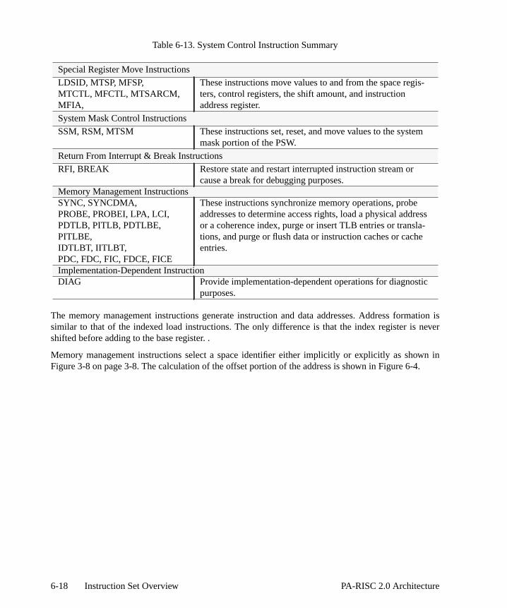
ation isnever
wn in.
ss
Table 6-13. System Control Instruction Summary
The memory management instructions generate instruction and data addresses. Address formsimilar to that of the indexed load instructions. The only difference is that the index register is shifted before adding to the base register. .
Memory management instructions select a space identifier either implicitly or explicitly as shoFigure 3-8 on page 3-8. The calculation of the offset portion of the address is shown in Figure 6-4
Special Register Move Instructions
LDSID, MTSP, MFSP,MTCTL, MFCTL, MTSARCM,MFIA,
These instructions move values to and from the space regis-ters, control registers, the shift amount, and instructionaddress register.
System Mask Control Instructions
SSM, RSM, MTSM These instructions set, reset, and move values to the systemmask portion of the PSW.
Return From Interrupt & Break Instructions
RFI, BREAK Restore state and restart interrupted instruction stream orcause a break for debugging purposes.
Memory Management InstructionsSYNC, SYNCDMA,PROBE, PROBEI, LPA, LCI,PDTLB, PITLB, PDTLBE,PITLBE,IDTLBT, IITLBT,PDC, FDC, FIC, FDCE, FICE
These instructions synchronize memory operations, probeaddresses to determine access rights, load a physical addreor a coherence index, purge or insert TLB entries or transla-tions, and purge or flush data or instruction caches or cacheentries.
Implementation-Dependent InstructionDIAG Provide implementation-dependent operations for diagnostic
purposes.
6-18 Instruction Set Overview PA-RISC 2.0 Architecture

n cost-icatingon theditional
tions toSpecialhat are
r
Assist Instructions
The PA-RISC design generally conforms to the concept of a simple instruction set implemented ieffective hardware. Certain algorithms can benefit from substantial performance gains by dedspecialized hardware to execute specialized instructions. Since few algorithms rely solely upspecialized hardware alone, it is usually advantageous to combine the central processor with adassist processors closely coupled to it.
In addition to the instructions executed by a central processor, the instruction set contains instrucinvoke the special, optional, hardware functions provided by the two types of assist processors: Function Units (SFUs) and coprocessors. Table 6-14 summarizes the assist instructions tprovided for SFUs and coprocessors.
Table 6-14. Assist Instruction Summary
Figure 6-4. System Operations
Special Function Instructions
SPOP0, SPOP1, SPOP2,SPOP3
These instructions invoke SFU operations, copy SFU registeror result to a general register, and perform a parameterizedSFU operation.
Coprocessor Instructions
COPR, CLDD, CLDW,CSTD, CSTW
These instructions invoke a coprocessor operation and load ostore words or doublewords to or from a coprocessor register.
0
31
Base
GeneralRegisters
32+
32
32
Index
Space ID Offset
Effective Address
,M Completer
0
31
Base
GeneralRegisters
+
32Index
Space ID Offset
3232
Effective Address
No Completer Specified
32
6-19PA-RISC 2.0 Architecture Instruction Set Overview

to the
perandsd so areunits.emory.
eneral
ptionalts PA-e is nottion in
in ative to
efinedrdware,traps to withoutpermit
uch astion-
uctions. by the Some
rationsade. An or the
used to
o thatulation
Special function units are closely coupled to the central processor and provide extensionsinstruction set. They use the general registers as operands and targets of operations.
Coprocessors provide functions that use either memory locations or coprocessor registers as oand targets of operations. Coprocessors are less closely coupled to the central processor, anmore easily provided as configuration options for an implementation than special function Coprocessors may also directly pass doubleword quantities to and from the coprocessor and mThis is suited to the manipulation of quantities that are too large to be directly handled in gregisters.
The special function unit and coprocessor instructions are intended to encapsulate all of the ohardware features used for non-system-level code. An emulation facility is provided that permiRISC family members to execute code using the standard instruction set when optional hardwarpresent. The emulation facility is provided by the assist emulation trap, which passes informacontrol registers, substantially reducing the instruction path length for emulation.
The assist exception trap permits partial implementations of standard “hardware” functionscombination of hardware and software. This handles functions that are difficult or not cost-effecimplement fully in hardware.
Compatibility Among Implementations
The standard PA-RISC instruction set contains all defined instructions, including those for all dassist processors. Particular implementations may choose to implement these instructions in hasoftware, or some combination of the two, using assist emulation traps and/or assist exception complete the implementation. Thus, these instructions can be used by compilers and assemblerssacrificing object-code portability. Software emulation of the extended functions is also used to execution of the object code in a degraded mode for high-availability systems.
Special Function Unit (SFU) Instructions
The SFU mechanism is intended for certain architecturally defined instruction extensions, shardware fixed-point binary multiply/divide or encryption hardware, as well as for implementaspecific extensions, such as emulation assist processors or direct I/O controller connections.
SFUs are connected to the general register interface and are invoked by special operation instrThese instructions cause the execution unit to perform any of several operations (determinedopcode extension), which may use the contents of registers, or may write back a result.instructions conditionally nullify the following instruction.
Some special function operations overlap their execution with succeeding instructions. These operequire that the special function unit’s state be saved and restored when a context switch is minterlock occurs if a special function result is requested before the operation has completed,special function unit is busy.
An SFU is not required to hold its state in addressable registers. Instead, SFU operations aresave and restore the state, as well as to pass it operands and receive results from it.
Defined special function units will conform to the requirements of the defined SFU instructions, sthey may be implemented either as built-in or interfaced special function units. The assist em
6-20 Instruction Set Overview PA-RISC 2.0 Architecture
levelse of the SFU
in the
t
hat is in thesition,
assedse theed to
R bit
at theinated uid i
statedoes SFUtate inid i is
assist
nds onpriority
rt
nd
trap permits software implementation of any defined special operation instruction.
The processor must also provide the current privilege level to special function units. Privilege could be broadcast each time they change or could be transmitted with each SFU operation. Usprivilege level by the SFU is specific to each of the units. The operation paragraph of eachinstruction description specifies the necessary information that must be available to the SFUsfu_operation function.
There is one SFU instruction, theIDENTIFY SFU (SPOP1) instruction, that is defined for all SFUs. Imust be implemented.
SFU Configuration Register
The SCR (SFU Configuration Register) is an 8-bit control register (within CR 10 bits 16..23) tused to indicate the presence and usability of a hardware implementation of an SFU. For all bitsSCR, SCR{i} corresponds to an undefined SFU with a unit identifier that is the same as the bit pothat is the SFU with uid i.
When SCR{i} is 1, the SFU with uid i is implied to be present and usable. SFU instructions are pto the SFU and the defined operation occurs. Exceptions resulting from the operation cauinstruction to be terminated with an assist exception trap. Assist emulation traps are not allowoccur for the SFU with uid i when SCR{i} is 1. It is an undefined operation to set to 1 the SCcorresponding to a nonexistent SFU.
When SCR{i} is 0, it is not implied that the SFU with uid i is absent from the system, but rather thSFU, if present, is not currently being used. When the SCR bit is 0, the SFU instruction is termwith an assist emulation trap. Assist exception traps are not allowed to occur for the SFU withwhen SCR{i} is 0.
Setting the SCR{i} bit to 0 must logically decouple the SFU with uid i. This must ensure that theof the SFU with uid i is frozen just prior to the transition of SCR{i} from 1 to 0 and that the state not change as long as SCR{i} is 0. When SCR{i} is 0, the SFU with uid i must not respond to anyoperations for the SFU with uid i. The frozen state of an SFU, for example, could also be a swhich the SFU is left “armed” to trap any subsequent operations. For example, if the SFU with uin an “armed-to-trap” state and SCR{i} is 0, any operation involving that SFU must not cause anexception trap.
The precedence of the interruptions that are applicable to operations for the SFU with uid i depethe state of SCR{i}. The assist exception trap and assist emulation trap are always taken in the order as described in “Interruption Priorities” on page 5-4.
NOTELogical decoupling may be accomplished in a variety of ways. Processors may use abosignals or other schemes to notify SFUs that the current instruction is to be ignored.
When the SCR bit is 0, logical decoupling suppresses any exception traps from an SFU acauses the emulation trap to occur (if it is the highest priority).
6-21PA-RISC 2.0 Architecture Instruction Set Overview

handlen setdatations canuctionsdware is
systemsocessorscessor’s
rom the from acessor’s
eeding is able
cessoreep their to save
erationsdditional
rmation
ave a
e
4..31)r. Bits 0s to theefined
Coprocessor Instructions
The coprocessor mechanism is intended for special-purpose data manipulations, for example todata larger than will fit in a general register. The interconnection method allows for instructioextensions with minimal effect on the instruction execution rate, while maintaining short communication paths between the coprocessors and the rest of the system. Coprocessor instrucbe executed by the coprocessor hardware or emulated by software. Combinations of instrimplemented in hardware and emulated by software are possible even when the coprocessor harpresent in a system.
When caches are implemented, coprocessors are connected to the CPU-cache interface. Forthat do not have a cache, coprocessors are connected to the CPU-memory bus interface. Coprmanipulate data in their own register sets, but use the data cache or memory bus and central proaddress generation logic. Under control of the CPU, coprocessor load instructions pass data fdata cache or memory bus to a coprocessor, and coprocessor store instructions pass datacoprocessor to the data cache or memory bus. Coprocessor operations use only the coproregisters. Some coprocessor operations may nullify the following instruction.
Coprocessor operation, load, and store instructions may overlap their execution with succinstructions. An interlock occurs if a coprocessor operation is requested before the coprocessorto perform it, and for loads and stores involving busy coprocessor registers.
The coprocessor load and store instructions contain a 5-bit field which normally specifies a coproregister, but may also be interpreted by coprocessors as a sub-operation field. Coprocessors kstate in their registers, so that storing the coprocessor registers and reloading them is sufficientand restore the state of a coprocessor.
Some coprocessors are capable of supporting doubleword load and store operations. These opare implemented on all systems that support such coprocessors, even though they may require acycles for some machines. Coprocessor load and store operations must be atomic.
The operation section of each coprocessor instruction description specifies the necessary infothat must be available to the coprocessor in thecoprocessor_op andsend_to_copr functions. There isone coprocessor instruction, theIDENTIFY COPROCESSOR (COPR,uid,0) instruction, that is defined forcoprocessors with unit identifiers 4 through 7. Coprocessors with unit identifiers 0 and 3 hmechanism to identify themselves that is individually defined.
NOTEAn unaligned data reference trap is taken if the appropriate number of rightmost bits of theffective virtual address are not zeros for theCOPROCESSOR LOAD WORD, COPROCESSORLOAD DOUBLEWORD, COPROCESSOR STORE WORD, and COPROCESSOR STOREDOUBLEWORD instructions. Absolute accesses to unaligned data are undefined operations.
Coprocessor Configuration Register
The CCR (Coprocessor Configuration Register) is an 8-bit control register (within CR 10 bits 2that is used to indicate the presence and usability of a hardware implementation of a coprocessoand 1 in the CCR correspond to the floating-point coprocessor and bit 2 in the CCR correspondperformance monitor coprocessor. For all other bits in the CCR, CCR{i} corresponds to an und
6-22 Instruction Set Overview PA-RISC 2.0 Architecture
uid i.
s an) with
essoring fromon trapsion to
athercessor occur
at thet thest notocessor,equent is 0,
h uid itaken in
rt
sor
ration
f sixteen
coprocessor with a unit identifier that is the same as the bit position, that is the coprocessor with
Execution of any floating-point instruction with CCR{0} and CCR{1} not set to the same value iundefined operation. Execution of a coprocessor operation instruction (major opcode 0x0CCCR{0}, CCR{1}, and the uid field in the instruction all set to 1 is an undefined operation.
When CCR{i} is 1, the coprocessor with uid i is implied to be present and usable. Coprocinstructions are passed to the coprocessor and the defined operation occurs. Exceptions resultthe operation cause the instruction to be terminated with an assist exception trap. Assist emulatiare not allowed to occur for the coprocessor with uid i when CCR{i} is 1. It is an undefined operatset to 1 the CCR bit corresponding to a nonexistent coprocessor.
When CCR{i} is 0, it is not implied that the coprocessor with uid i is absent from the system, but rthat the coprocessor, if present, is not currently being used. When the CCR bit is 0, the coproinstruction is terminated with an assist emulation trap. Assist exception traps are not allowed tofor the coprocessor with uid i when CCR{i} is 0.
Setting the CCR{i} bit to 0 must logically decouple the coprocessor with uid i. This must ensure thstate of the coprocessor with uid i is frozen just prior to the transition of CCR{i} from 1 to 0 and thastate does not change as long as CCR{i} is 0. When CCR{i} is 0, the coprocessor with uid i murespond to any coprocessor operations for the coprocessor with uid i. The frozen state of a coprfor example, could also be a state in which the coprocessor is left “armed” to trap any subsoperations. For example, if the coprocessor with uid i is in an “armed-to-trap” state and CCR{i}any operation involving that coprocessor must not cause an assist exception trap.
The precedence of the interruptions that are applicable to operations for the coprocessor witdepends on the state of CCR{i}. The assist exception trap and assist emulation trap are always the priority order as described in “Interruption Priorities” on page 5-4.
NOTELogical decoupling may be accomplished in a variety of ways. Processors may use abosignals or other schemes to notify coprocessors that the current instruction is to be ignored.
When the CCR bit is 0, logical decoupling suppresses any exception traps from a coprocesand causes the emulation trap to occur (if it is the highest priority).
Conditions and Control Flow
Many instructions utilize conditions derived from the values of the operators and the opeperformed. The architecture defines several sets of conditions that affect control flow:
• Arithmetic/Logical Conditions.
• Unit Conditions.
• Shift/Extract/Deposit Conditions.
• Branch On Bit Conditions.
Every instruction that tests conditions uses one of these sets. Each set contains a maximum o
6-23PA-RISC 2.0 Architecture Instruction Set Overview

lect the
s all the
lled by
s:
ceeds
defined,
. (Seecode trap.
se aregrity isa givenuence of could
ns but
n trap or
avoiderved
separate conditions and their negations. Most instructions that use conditions may also senegation of a condition.
The condition completer field,cond, in the assembly language form of the instructions specifiecondition or the negation of a condition. This field expands in the machine language form to ficondition field,c, (normally 3 bits wide), the 1-bit negation field,f, and the 1-bit doubleword field,d, asrequired. For some instructions, the negation or doubleword attributes of the condition are controthe opcode.
The result of an operation and the specified condition can affect control flow in the following way
• Branching – the result determines whether or not the branch is taken.
• Nullifying – the result determines whether or not the next instruction is nullified.
• Trapping – the result determines whether a conditional trap is taken or execution pronormally.
Additional Notes on the Instruction Set
This section defines how the architecture and instruction notation handles such details as unillegal, null, and unimplemented instructions.
Undefined and Illegal Instructions
Not all of the 64 possible major opcodes of the instruction set are defined as valid instructionsAppendix C, “Operation Codes”, for a list of the valid instruction opcodes.) An undefined major opis considered an illegal instruction. Execution of an illegal instruction causes an illegal instruction
Within each major opcode, there may be undefined opcode extensions and modifiers (theundefined instructions). Interpretation of these opcodes is left to the implementor, but system intenot compromised. An undefined instruction, or sequence of undefined instructions, executed at privilege level has no effect on system state other than what would have been produced by a seqdefined instructions running at the same privilege level. This limits the possible side-effects thatresult from undefined instructions.
Undefined operations are equivalently specified. These result from normally defined instructiowith operands or specifiers that are explicitly disallowed.
Executing an optional special operation or coprocessor instruction may cause an assist exceptioan action that depends on the definition of the specific special function unit or coprocessor.
Reserved Instruction Fields
In the Format section of the instruction description pages in Chapter 7, instruction fields markedrv areReserved instruction fields. These fields are reserved for future architectural definition. To incompatibility with future revisions of the architecture, software must provide zeros in all Resfields. When decoding instructions, processors must ignore Reserved instruction fields.
6-24 Instruction Set Overview PA-RISC 2.0 Architecture

avoidalues. specific
ect of anted.
B-bit, N-
Reserved Values of an Instruction Field
Certain values of some instruction fields are Reserved for future architectural definition. To incompatibility with future revisions of the architecture, software must not use the Reserved vWhen decoding instructions, processors must treat the Reserved values as described for thefield.
Null Instructions
Null instructions occur when unimplemented features of the architecture are accessed. The effnull instruction is identical to a nullified instruction except that the Recovery Counter is decremeThere is no effect on the machine state except that the IA queues are advanced and the PSW bit, X-bit, Y-bit, and Z-bit are set to 0.
6-25PA-RISC 2.0 Architecture Instruction Set Overview

6-26 Instruction Set Overview PA-RISC 2.0 Architecture

whichcture.
ation
7 Instruction Descriptions
This chapter provides a description of each of the instructions (except floating-point instructions are described in Chapter 9, “Floating-Point Instruction Set”) supported by the PA-RISC architeThe instructions are listed in alphabetical order, according to the instruction’s mnemonic.
Figure 7-1 illustrates the information presented in each of the instruction descriptions. The informpresented in this figure is for illustrative purposes only and does not represent a valid instruction.
Figure 7-1. Instruction Description Example
DO OPERATION DO
Format: DO,cond r1,r2,t
(3)
Purpose: To perform a 32-bit, bitwise DO operation.
Description: GRr1 and GRr2 are DOed and the result is placed in GRt. Thefollowing instruction is nullified if the values DOed satisfy thespecified condition,cond. The condition is encoded in thec andffields of the instruction.
Conditions: The condition is any of the 32-bit logical conditions shown inTable I on page I-1. When a condition completer is not specified,the “never” condition is used. The boolean variable“cond_satisfied” in the operation section is set when the valuesDOed satisfy the specified condition.
Operation: GR[t]← GR[r1] DO GR[r2];if (cond_satisfied) PSW[N]← 1;
Exceptions: None
Restrictions: None
Notes: The DOIT pseudo-operation allows for the transformation of datafrom one register to another by generating the instruction DO r,0,t.The DONT pseudo-operation generates the instruction DO 0,0,0.
Op r2 r1 c f 12 t6 5 5 3 1 7 5
Instruction mnemonic and descriptive name
Assembly languagesource statement syntax
Opcode and fields ofthe instruction format
Short description ofinstruction operation
Full description ofinstruction operation
Equations that describeinstruction operation
Defined conditions thatcould cause an interruption
General restrictions oninstruction usage
General notes onimplementation
Condition codes that arevalid for the instruction
7-98 Instruction Set Description PA-RISC 1.1 Architec-
The number of the format asdefined in Appendix B,
“Instruction Formats”
7-1PA-RISC 2.0 Architecture Instruction Descriptions

add/. Thery
ion,
gned
/
ther a
d
r anyleterd” in
Add ADD
Format: ADD,cmplt,carry,cond r1,r2,t
(8)
Purpose: To do 64-bit integer addition and conditionally nullify the following instruction.
Description: GR r1 and GRr2 are added. If no trap occurs, the result is placed in GRt. The variable“carry_borrows” in the operation section captures the 4-bit carries resulting from theoperation. The completer,cmplt, encoded in thee1 field, specifies whether the carryborrow bits in the PSW are updated and whether a trap is taken on signed overflowcompleter,carry, encoded in thee2 field, specifies whether the addition is done with carin.
The following instruction is nullified if the values added satisfy the specified conditcond. The condition is encoded in thec, d, and f fields of the instruction. The booleanvariable "overflow" in the operation section is set if the operation results in a 32-bit sioverflow (d=0) or a 64-bit signed overflow (d=1.) For addition with carry in, thed fieldencodes whether the word carry (PSW C/B{8},d=0), or the doubleword carry (PSW CB{0}, d=1) is used.
Thee1 field encodes whether the carry/borrow bits in the PSW are updated and whetrap is taken on overflow (e1=1: carries updated, no trap,e1=2: carries not updated, notrap,e1=3: carries updated, trap on overflow.) Thee2 field encodes whether addition withcarry in is performed (e2=0: no carry in,e2=1: addition performed with carry in.) Thecombination e1=2, e2=1 is not defined. The following table shows the allowecombinations:
Conditions: The condition is any of the 32-bit add conditions shown in Table D-6 on page D-5 oof the 64-bit add conditions shown in Table D-7 on page D-6. When a condition compis not specified, the “never” condition is used. The boolean variable “cond_satisfiethe operation section is set when the values added satisfy the specified condition.
02 r2 r1 c f e1 1 e2 0 d t
6 5 5 3 1 2 1 1 2 1 5
Completer Description e1 e2
<none> Add 1 0C or DC Add with carry/doubleword carry 1 1L Add logical 2 0TSV Add and trap on signed overflow 3 0C,TSV or DC,TSV Add with carry/doubleword carry
and trap on signed overflow3 1
7-2 Instruction Descriptions PA-RISC 2.0 Architecture

,DC
Operation: switch (carry) {case C: res← GR[r1] + GR[r2] + PSW[C/B]{8};
break;case DC: res← GR[r1] + GR[r2] + PSW[C/B]{0};
break;default: res← GR[r1] + GR[r2];
break;}if (cmplt == TSV && overflow)
overflow_trap;else {
GR[t] ← res;if (cmplt != ’L’)
PSW[C/B] ← carry_borrows;if (cond_satisfied) PSW[N]← 1;
}
Exceptions: Overflow trap
Notes: When the ,C completer is specified, only 32-bit conditions are available. When thecompleter is specified, only 64-bit conditions are available.
7-3PA-RISC 2.0 Architecture Instruction Descriptions
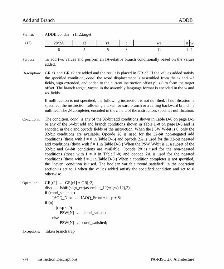
alues
target
isch is.
-5nd ise addatedf the
gatedatedfied,tiont to 0
Add and Branch ADDB
Format: ADDB,cond,n r1,r2,target
(17)
Purpose: To add two values and perform an IA-relative branch conditionally based on the vadded.
Description: GR r1 and GRr2 are added and the result is placed in GRr2. If the values added satisfythe specified condition,cond, the word displacement is assembled from thew and w1fields, sign extended, and added to the current instruction offset plus 8 to form the offset. The branch target,target, in the assembly language format is encoded in thew andw1 fields.
If nullification is not specified, the following instruction is not nullified. If nullification specified, the instruction following a taken forward branch or a failing backward brannullified. The ,N completer, encoded in then field of the instruction, specifies nullification
Conditions: The condition,cond, is any of the 32-bit add conditions shown in Table D-6 on page Dor any of the 64-bit add and branch conditions shown in Table D-8 on page D-6 aencoded in thec andopcode fields of the instruction. When the PSW W-bit is 0, only th32-bit conditions are available. Opcode 28 is used for the 32-bit non-negatedconditions (those with f = 0 in Table D-6) and opcode 2A is used for the 32-bit negadd conditions (those with f = 1 in Table D-6.) When the PSW W-bit is 1, a subset o32-bit and 64-bit conditions are available. Opcode 28 is used for the non-neconditions (those with f = 0 in Table D-8) and opcode 2A is used for the negconditions (those with f = 1 in Table D-8.) When a condition completer is not specithe “never” condition is used. The boolean variable “cond_satisfied” in the operasection is set to 1 when the values added satisfy the specified condition and seotherwise.
Operation: GR[r2] ← GR[r1] + GR[r2];disp ← lshift(sign_ext(assemble_12(w1,w),12),2);if (cond_satisfied)
IAOQ_Next ← IAOQ_Front + disp + 8;if (n)
if (disp < 0)PSW[N] ← !cond_satisfied;
elsePSW[N] ← cond_satisfied;
Exceptions: Taken branch trap
28/2A r2 r1 c w1 n w
6 5 5 3 11 1 1
7-4 Instruction Descriptions PA-RISC 2.0 Architecture

ion.
ue isn
bitr,satisfy table
the
in a
henriableecified
Add to Immediate ADDI
Format: ADDI,cmplt,trapc,cond i,r,t
(9)
Purpose: To add an immediate value to a register and conditionally nullify the following instruct
Description: The sign-extended immediate valuei is added to GRr. If no trap occurs, the result isplaced in GRt and the carry/borrow bits in the PSW are updated. The immediate valencoded into theim11 field. The variable “carry_borrows” in the operation sectiocaptures the 4-bit carries resulting from the add operation.
The completer,cmplt, encoded in thee1field, specifies whether a trap is taken on a 32-signed overflow (e1=0: no trap,e1=1: trap on 32-bit signed overflow.) The completetrapc, encoded in the opcode, specifies whether a trap is taken if the values added the condition specified (no trap for opcode 2D, trap on condition for opcode 2C.) Thebelow shows thecmplt andtrapc combinations.
For opcode 2D, the following instruction is nullified if the values added satisfy specified condition,cond. The condition is encoded in thec andf fields of the instruction.The boolean variable “overflow” in the operation section is set if the operation results32-bit signed overflow.
Conditions: The condition is any of the 32-bit add conditions shown in Table D-6 on page D-5. Wa condition completer is not specified, the “never” condition is used. The boolean va“cond_satisfied” in the operation section is set when the values added satisfy the spcondition.
Operation: res ← low_sign_ext(im11,11) + GR[r];if (cmplt == TSV && overflow)
overflow_trap;else if (trapc == TC && cond_satisfied)
conditional_trap;else {
GR[t] ← res;PSW[C/B] ← carry_borrows;if (cond_satisfied) PSW[N]← 1;
}
Exceptions: Overflow trap Conditional trap
2C/2D r t c f e1 im11
6 5 5 3 1 1 11
Completer Description Opcode e1
<none> Add to immediate 2D 0TSV Add to immediate and trap on signed overflow 2D 1TC Add to immediate and trap on condition 2C 0TSV, TC Add to immediate and trap on signed overflow
or condition2C 1
7-5PA-RISC 2.0 Architecture Instruction Descriptions

alues
tion
isch is.
-5nd ise addatedf the
gatedatedfied,tiont to 0
Add Immediate and Branch ADDIB
Format: ADDIB,cond,n i,r,target
(17)
Purpose: To add two values and perform an IA-relative branch conditionally based on the vadded.
Description: The sign-extended immediate valueim5 is added to GRr and the result is placed in GRr.If the values added satisfy the specified condition,cond, the word displacement isassembled from thew andw1 fields, sign extended, and added to the current instrucoffset plus 8 to form the target offset. The branch target,target, in the assembly languageformat is encoded in thew andw1 fields.
If nullification is not specified, the following instruction is not nullified. If nullification specified, the instruction following a taken forward branch or a failing backward brannullified. The ,N completer, encoded in then field of the instruction, specifies nullification
Conditions: The condition,cond, is any of the 32-bit add conditions shown in Table D-6 on page Dor any of the 64-bit add and branch conditions shown in Table D-8 on page D-6 aencoded in thec andopcode fields of the instruction. When the PSW W-bit is 0, only th32-bit conditions are available. Opcode 29 is used for the 32-bit non-negatedconditions (those with f = 0 in Table D-6) and opcode 2B is used for the 32-bit negadd conditions (those with f = 1 in Table D-6.) When the PSW W-bit is 1, a subset o32-bit and 64-bit conditions are available. Opcode 29 is used for the non-neconditions (those with f = 0 in Table D-8) and opcode 2B is used for the negconditions (those with f = 1 in Table D-8.) When a condition completer is not specithe “never” condition is used. The boolean variable “cond_satisfied” in the operasection is set to 1 when the values added satisfy the specified condition and seotherwise.
Operation: GR[r] ← low_sign_ext(im5,5) + GR[r];disp ← lshift(sign_ext(assemble_12(w1,w),12),2);if (cond_satisfied)
IAOQ_Next ← IAOQ_Front + disp + 8;if (n)
if (disp < 0)PSW[N] ← !cond_satisfied;
elsePSW[N] ← cond_satisfied;
Exceptions: Taken branch trap
29/2B r im5 c w1 n w
6 5 5 3 11 1 1
7-6 Instruction Descriptions PA-RISC 2.0 Architecture

to
Add Immediate Left ADDIL
Format: ADDIL i,r,r1
(7)
Purpose: To add the upper portion of a 32-bit immediate value to a general register.
Description: The 21-bit immediate value,i, is assembled, shifted left 11 bits, sign extended, added GR r and placed in GR1. Overflow, if it occurs, is ignored.
Operation: GR[1] ← sign_ext(lshift(assemble_21(im21),11),32) + GR[r];
Exceptions: None
Programming NoteADD IMMEDIATE LEFT can be used to perform a load or store with a 32-bit displacement. Forexample, to load a word from memory into general registert with a 32-bit displacement, thefollowing sequence of assembly language code could be used:
0A r im21
6 5 21
ADDIL l%literal,GRb
LDW r%literal(0,GR1),GRt
7-7PA-RISC 2.0 Architecture Instruction Descriptions
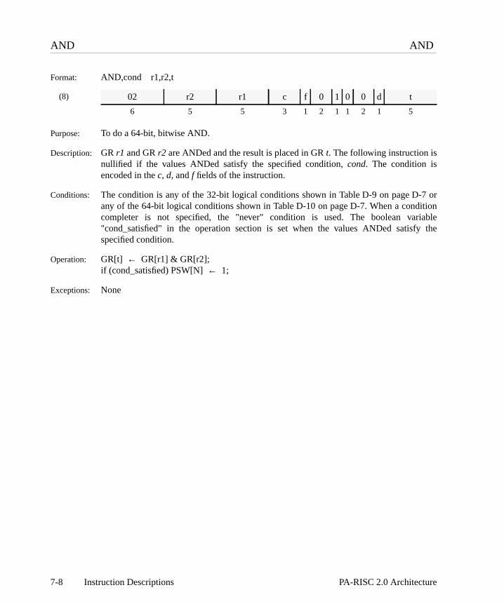
7 oritioniable the
AND AND
Format: AND,cond r1,r2,t
(8)
Purpose: To do a 64-bit, bitwise AND.
Description: GR r1 and GRr2 are ANDed and the result is placed in GRt. The following instruction isnullified if the values ANDed satisfy the specified condition,cond. The condition isencoded in thec, d, andf fields of the instruction.
Conditions: The condition is any of the 32-bit logical conditions shown in Table D-9 on page D-any of the 64-bit logical conditions shown in Table D-10 on page D-7. When a condcompleter is not specified, the "never" condition is used. The boolean var"cond_satisfied" in the operation section is set when the values ANDed satisfyspecified condition.
Operation: GR[t] ← GR[r1] & GR[r2];if (cond_satisfied) PSW[N]← 1;
Exceptions: None
02 r2 r1 c f 0 1 0 0 d t
6 5 5 3 1 2 1 1 2 1 5
7-8 Instruction Descriptions PA-RISC 2.0 Architecture

7 oritioniable the
AND Complement ANDCM
Format: ANDCM,cond r1,r2,t
(8)
Purpose: To do a 64-bit bitwise AND with complement.
Description: GR r1 is ANDed with the one’s complement of GRr2 and the result is placed in GRt. Thefollowing instruction is nullified if the values ANDed satisfy the specified condition,cond.The condition is encoded in thec, d, andf fields of the instruction.
Conditions: The condition is any of the 32-bit logical conditions shown in Table D-9 on page D-any of the 64-bit logical conditions shown in Table D-10 on page D-7. When a condcompleter is not specified, the "never" condition is used. The boolean var"cond_satisfied" in the operation section is set when the values ANDed satisfyspecified condition.
Operation: GR[t] ← GR[r1] & ∼GR[r2];if (cond_satisfied) PSW[N]← 1;
Exceptions: None
02 r2 r1 c f 0 0 0 0 d t
6 5 5 3 1 2 1 1 2 1 5
7-9PA-RISC 2.0 Architecture Instruction Descriptions

ith a
is form
the
argetecutes
ge-fg
gedhen
used
if a
d.
the3-14.
is
Branch B
Format: B,cmplt,stack,n target,t
(20)
Purpose: To do IA-relative branches with optional privilege level change and procedure calls wstatic displacement.
Description: The word displacement is assembled from thew, w1, w2,and (when the ,L completer isspecified with GR 2 as the link register)w3 fields in the instruction. The displacement sign extended, and the result plus 8 is added to the offset of the current instruction tothe target offset.
The completer,stack, specifies whether the offset of the return point is pushed ontobranch target stack. If the ,L completer is specified and the ,PUSH completer is specified,either the offset of the return point or an “invalid” value is pushed onto the branch tstack. On machines that do not implement the branch target stack, the instruction exthe same as if the ,PUSH completer had not been specified.
The completer,cmplt, specifies whether a return link is saved, or whether a privileincreasingGATEWAY function is performed. If the ,L completer is specified, the offset othe return point is placed in GRt. The return point is 4 bytes beyond the followininstruction.
If the ,GATE completer is specified and the PSW C-bit is 1, the privilege level is chanto that given by the two rightmost bits of the type field in the TLB entry for the page (wthe type field is greater than 3) from which theBRANCH instruction is fetched if thatresults in a higher privilege. If privilege is not increased, then the current privilege is at the target. In all cases, the privilege level of theBRANCH instruction is deposited intobits 62..63 of GRt. The privilege change occurs at the target of theBRANCH. If the PSWC-bit is 0, the privilege level is changed to 0. An illegal instruction trap is taken BRANCH instruction is attempted with the ,GATE completer and the PSW B-bit is 1.
If the ,GATE completer is specified, sub-opcode 1 is used. If the ,L completer is specifiedand the target register is GR 2, sub-opcode 5 is used. If the ,L completer is specified, thetarget register is GR 2, and the ,PUSH completer is specified, sub-opcode 4 is useOtherwise, sub-opcode 0 is used.
The variable “page_type” is set to the value of the access rights field, bits {0..2}, fromtranslation used to fetch the instruction. See “Access Rights Interpretation” on page
The following instruction is nullified if the ,N completer is specified. The completer encoded in then field of the instruction. The branch target,target, in the assemblylanguage format is encoded in thew, w1, w2, and (when GR 2 is the link register) w3fields.
3A t/w3 w1 0/1/4/5 w2 n w
6 5 5 3 11 1 1
7-10 Instruction Descriptions PA-RISC 2.0 Architecture

henf the
ation
rform
target
Operation: if (cmplt == ‘GATE’ && PSW[B])illegal_instruction_trap;
else {if (cmplt == ‘L’ && t == GR2) {
disp ← lshift(sign_ext(assemble_22(w3,w1,w2,w),22),2)if(stack == ‘PUSH’)
push_onto_BTS(( IAOQ_Back + 4){0..61});}else
disp ← lshift(sign_ext(assemble_17(w1,w2,w),17),2);if (cmplt == ‘GATE’) {
GR[t] ← cat(GR[t]{0..61},IAOQ_Front{62..63});if (PSW[C]) {
if (page_type <= 3)priv ← IAOQ_Front{62..63};
elsepriv ← min(IAOQ_Front{62..63}, page_type{1..2});
} elsepriv ← 0;
elsepriv ← IAOQ_Front{62..63};
IAOQ_Next{0..61} ← (IAOQ_Front + disp + 8){0..61};IAOQ_Next{62..63} ← priv;if (cmplt == ‘L’) {
GR[t] ← IAOQ_Back + 4;BNR ← ( IAOQ_Back + 4){0..61};
}if (n) PSW[N] ← 1;
}
Exceptions: Illegal instruction trapTaken branch trap
Notes: When the ,GATE completer is specified, the privilege information must be captured wthe TLB is read for instruction fetch and that information kept for the determination onew execution privilege.
To perform an unconditional branch without saving a link, the B,n target pseudo-opergenerates a a B,L,n target,%R0 instruction with GR0 as the link register.
The CALL,n target pseudo-operation generates a B,L,n target,%R2 instruction to pea procedure call with GR2 specified as the link register.
Restrictions: The ,PUSH completer can be used only if the ,L completer is specified and the register is GR2.
7-11PA-RISC 2.0 Architecture Instruction Descriptions

e,
el.
Programming NoteIt is possible for aBRANCH to promote the privilege level so that the process cannot continueexecuting on that page (because it violates PL2 of the TLB access rights field.) In that cassoftware should ensure that theBRANCH nullifies execution of the following instruction and itstarget should be on a page whose range of execute levels includes the new privilege levOtherwise, an instruction memory protection trap may result.
7-12 Instruction Descriptions PA-RISC 2.0 Architecture

r.
the
be
< or wordr
f
r bits.
ord
isch is.
-9.e bit
Branch on Bit BB
Format: BB,cond,n r,pos,target
(18)
Purpose: To perform an IA-relative branch conditionally based on the value of a bit in a registe
Description: If the bit in GRr specified bypos satisfies the condition,cond, the word displacement isassembled from thew andw1 fields of the instruction, sign extended, and added to current instruction offset plus 8 to form the target offset. The branch target,target, in theassembly language format is encoded in thew andw1 fields.
The bit position,pos, can either be a constant (fixed bit position, opcode 31), or canSAR, the Shift Amount Register (CR 11) (variable bit position, opcode 30.)
With a fixed bit position, thep field encodes the lower 5 bits ofpos, and thed field encodeseither 0 or the complement of the upper bit. If a word condition is specified (either >=), pos may take on the values 0..31, and the bit tested is one of the bits in the lowerof GRr. For word conditions, thed field is 0. If a doubleword condition is specified (eithe*< or *>=), pos may take on the values 0..63, and the complement of the upper bit oposis encoded in thed field. Any bit in the doubleword in GRr may be tested.
With a variable bit position, thep field is 0. If a word condition is specified (either < o>=), the leftmost bit of the SAR is ignored, and 32 is added to the value in the lower 5Thus, the bit tested is one of the bits in the lower word of GRr. If a doubleword conditionis specified (either *< or *>=), the full value of the SAR is used. Any bit in the doublewin GRr may be tested. For word conditions, thed field is 0; for doubleword conditions, thed field is 1.
If nullification is not specified, the following instruction is not nullified. If nullification specified, the instruction following a taken forward branch or a failing backward brannullified. The ,N completer, encoded in then field of the instruction, specifies nullification
Conditions: The condition,cond, is any of the branch on bit conditions from Table D-15 on page DThe boolean variable “cond_satisfied” in the operation section is set to 1 when thtested satisfies the specified condition and set to 0 otherwise.
30/31 p r c 1 d w1 n w
6 5 5 1 1 1 11 1 1
7-13PA-RISC 2.0 Architecture Instruction Descriptions

Operation: if (variable_bit_position)if (cond == < || cond == >=) /* word conditions */
shamt← CR[11]{1..5} + 32;else /* doubleword conditions */
shamt← CR[11];else
shamt← cat(~cp,p);lshift(GR[r],shamt);disp ← lshift(sign_ext(assemble_12(w1,w),12),2);if (cond_satisfied)
IAOQ_Next ← IAOQ_Front + disp + 8;if (n)
if (disp < 0)PSW[N] ← !cond_satisfied;
elsePSW[N] ← cond_satisfied;
Exceptions: Taken branch trap
7-14 Instruction Descriptions PA-RISC 2.0 Architecture

thed theode
ntits of
tion
is
Branch External BE
Format: BE,n wd(sr,b)BE,L,n wd(sr,b),sr0,r31
(19)
Purpose: To do procedure calls, branches and returns to another space.
Description: The word displacement,wd, is assembled from thew, w1, andw2 fields in the instruction.The displacement is sign extended and added to GRb to form the target offset. SRsr(which is assembled from thes field of the instruction) becomes the target space.
If the ,L completer is specified, the offset of the return point is placed in GR 31 andspace of the return point is placed in SR 0. The return point is 4 bytes beyonfollowing instruction. If the ,L completer is specified, opcode 39 is used; otherwise opc38 is used.
If the two rightmost bits of GRb designate a lower privileged level than the curreinstruction, the privilege level of the target is set to that specified by the rightmost bGR b. The decrease in privilege level takes effect at the branch target.
When aBRANCH EXTERNAL is executed with the PSW C-bit 0 (code address translais disabled) the effect on IASQ (and SR 0 if the ,L completer is specified) is not defined.
The following instruction is nullified if the ,N completer is specified. The completer encoded in then field of the instruction.
Operation: disp ← lshift(sign_ext(assemble_17(w1,w2,w),17),2);IAOQ_Next{0..61} ← (GR[b] + disp){0..61};if (IAOQ_Front{62..63} < GR[b]{62..63})
IAOQ_Next{62..63} ← GR[b]{62..63};else
IAOQ_Next{62..63} ← IAOQ_Front{62..63};IASQ_Next ← SR[assemble_3(s)];if (cmplt == L) {
GR[31] ← IAOQ_Back + 4;SR[0] ← IASQ_Back;
}if (n) PSW[N] ← 1;
Exceptions: Taken branch trap
38/39 b w1 s w2 n w
6 5 5 3 11 1 1
7-15PA-RISC 2.0 Architecture Instruction Descriptions

w
Programming NoteIf a taken local branch is executed following aBRANCH EXTERNAL instruction, the target’saddress is computed based on the value of the IASQ set by theBRANCH EXTERNALinstruction. This results in a transfer of control to possibly a meaningless location in the nespace.
7-16 Instruction Descriptions PA-RISC 2.0 Architecture

theR
is
is
Branch and Link Register BLR
Format: BLR,n x,t
(21)
Purpose: To do IA-relative branches with a dynamic displacement and store a return link.
Description: The index from GRx is shifted left 3 bits and the result plus 8 is added to the offset ofcurrent instruction to form the target offset. The offset of the return point is placed in Gt.The return point is 4 bytes beyond the following instruction.
The following instruction is nullified if the ,N completer is specified. The completer encoded in then field of the instruction.
Operation: IAOQ_Next ← IAOQ_Front + lshift(GR[x],3) + 8;GR[t] ← IAOQ_Back + 4;if (n) PSW[N] ← 1;
Exceptions: Taken branch trap
Programming NoteBRANCH AND LINK REGISTER with GR 0 as the link register does a IA-relative branchwithout saving a link. Jump tables based on the index value can be constructed using thinstruction. When the jump table begins at the instruction which is located at theBLR plus 8bytes, an index value of 0 can be used to branch to the first entry of the table.
3A t x 2 0 n 0
6 5 5 3 11 1 1
7-17PA-RISC 2.0 Architecture Instruction Descriptions

Break BREAK
Format: BREAK im5,im13
(27)
Purpose: To cause a break instruction trap for debugging purposes.
Description: A break instruction trap occurs when this instruction is executed.
Operation: break_instruction_trap;
Exceptions: None
Notes: im5 andim13 can be used as parameters to the "BREAK" processing code.
00 im13 00 im5
6 13 8 5
7-18 Instruction Descriptions PA-RISC 2.0 Architecture

is
ntt bits
Branch Vectored BV
Format: BV,n x(b)
(21)
Purpose: To do base-relative branches with a dynamic displacement in the same space.
Description: The index from GRx is shifted left 3 bits and the result is added to GRb to form the targetoffset.
The following instruction is nullified if the ,N completer is specified. The completer encoded in then field of the instruction.
If the two rightmost bits of GRb designate a lower privilege level than the curreprivilege level, the privilege level of the target is set to that specified by the rightmosof GRb. The decrease in privilege level takes effect at the branch target.
Operation: IAOQ_Next{0..61} ← (GR[b] + lshift(GR[x],3)){0..61};if (IAOQ_Front{62..63} < GR[b]{62..63})
IAOQ_Next{62..63} ← GR[b]{62..63};else
IAOQ_Next{62..63} ← IAOQ_Front{62..63};if (n) PSW[N] ← 1;
Exceptions: Taken branch trap
3A b x 6 0 n 0
6 5 5 3 11 1 1
7-19PA-RISC 2.0 Architecture Instruction Descriptions

If no not
e top
getgetes
fhiness if the
turnsub-n is
is
ntmost
ss
Branch Vectored External BVE
Format: BVE,stack,n (b)BVE,L,stack,n (b),r2
(22)
Purpose: To do base-relative branches and procedure calls to another space.
Description: Either GRb or the branch target stack provides the offset of the target instruction.
The completer,stack, specifies whether a branch target stack operation is performed. completer is specified, GRb provides the target offset and the branch target stack ischanged.
If the ,POP completer is specified and if the branch target stack is non-empty and thentry is valid, the target offset can be provided by either GRb or the top entry of thebranch target stack. If the ,POP completer is specified, the top entry of the branch tarstack is popped. If the ,POP completer is specified and the top entry of the branch tarstack is valid and does not equal the value in GRb, the results are undefined. On machinthat do not implement the branch target stack, GRb provides the target offset.
If the ,L completer is specified and the ,PUSH completer is specified, either the offset othe return point or an “invalid” value is pushed onto the branch target stack. On macthat do not implement the branch target stack, the instruction executes the same a,PUSH completer had not been specified.
If a stack completer is specified, thep field is 1. Otherwise thep field is 0.
If the ,L completer is specified, the offset of the return point is placed in GR 2. The repoint is 4 bytes beyond the following instruction. The completer is encoded in the opcode field of the instruction (6: no link, 7: link.) The space of the target instructiospecified implicitly by the base register. The upper two bits of GRb are added to 4 toselect a space register which gives the target space.
The following instruction is nullified if the ,N completer is specified. The completer encoded in then field of the instruction.
If the two rightmost bits of GRb designate a lower privilege level than the curreprivilege level, then the privilege level of the target is set to that specified by the rightbits of GRb. The decrease in privilege level takes effect at the branch target.
When aBRANCH VECTORED EXTERNAL is executed with the PSW C-bit 0 (code addretranslation is disabled) the effects on IASQ are not defined.
3A b 0 6/7 1 rv n p
6 5 5 3 1 10 1 1
7-20 Instruction Descriptions PA-RISC 2.0 Architecture

m an
edure
Operation: if (stack == ‘POP’) {tmp ← pop_from_BTS();valid ← tmp{62};if (valid)
IAOQ_Next{0..61} ← tmp{0..61};else
IAOQ_Next{0..61} ← GR[b]{0..61};}if (IAOQ_Front{62..63} < GR[b]{62..63})
IAOQ_Next{62..63} ← GR[b]{62..63};else
IAOQ_Next{62..63} ← IAOQ_Front{62..63};if (cmplt == L) {
GR[2] ← IAOQ_Back + 4;BNR ← ( IAOQ_Back + 4){0..61};if (stack == ‘PUSH’)
push_onto_BTS(( IAOQ_Back + 4){0..61});}IASQ_Next← space_select(0, GR[b],LONG_DISP);if (n) PSW[N] ← 1;
Exceptions: Taken branch trap.
Notes: The CALL,n (b) pseudo-operation generates a BVE,L,n (b),%R2 instruction to perforindirect procedure call with GR2 specified as the link register.
The RET,n pseudo-operation generates a BVE,n (%R2) instruction to perform a procreturn.
7-21PA-RISC 2.0 Architecture Instruction Descriptions
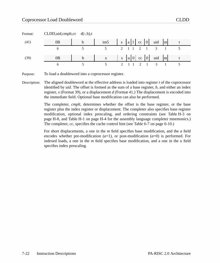
o
baseegister3 onnics.)
Coprocessor Load Doubleword CLDD
Format: CLDD,uid,cmplt,cc d(s,b),t
(41)
(39)
Purpose: To load a doubleword into a coprocessor register.
Description: The aligned doubleword at the effective address is loaded into registert of the coprocessoridentified byuid. The offset is formed as the sum of a base register,b, and either an indexregister,x (Format 39), or a displacementd (Format 41.) The displacement is encoded intthe immediate field. Optional base modification can also be performed.
The completer,cmplt, determines whether the offset is the base register, or the register plus the index register or displacement. The completer also specifies base rmodification, optional index prescaling, and ordering constraints (see Table H-page H-8, and Table H-1 on page H-4 for the assembly language completer mnemoThe completer,cc, specifies the cache control hint (see Table 6-7 on page 6-10.)
For short displacements, a one in them field specifies base modification, and thea fieldencodes whether pre-modification (a=1), or post-modification (a=0) is performed. Forindexed loads, a one in them field specifies base modification, and a one in theu fieldspecifies index prescaling.
0B b im5 s a 1 cc 0 uid m t
6 5 5 2 1 1 2 1 3 1 5
0B b x s u 0 cc 0 uid m t
6 5 5 2 1 1 2 1 3 1 5
7-22 Instruction Descriptions PA-RISC 2.0 Architecture

Operation: if (indexed_load) /* indexed (Format 39)*/switch (cmplt) {
case S:case SM: dx← lshift(GR[x],3);
break;case M:default: dx← GR[x];
break;}
} else /* short displacement */dx ← low_sign_ext(im5,5); /* (Format 41) */
space← space_select(s,GR[b],format);switch (cmplt) {
case MB: offset← GR[b] + dx;GR[b] ← GR[b] + dx;break;
case MA:case M:case SM: offset← GR[b];
GR[b] ← GR[b] + dx;break;
default: offset← GR[b] + dx;break;
}send_to_copr(uid,t);CPR[uid][t] ← mem_load(space,offset,0,63,cc);if (cmplt == O)
enforce_ordered_load;
Exceptions: Assist exception trap Unaligned data reference trapData TLB miss fault/data page fault Page reference trapData memory access rights trap Data memory protection ID trapAssist emulation trap
Restrictions: If the completerO is specified, the displacement must be 0.
7-23PA-RISC 2.0 Architecture Instruction Descriptions
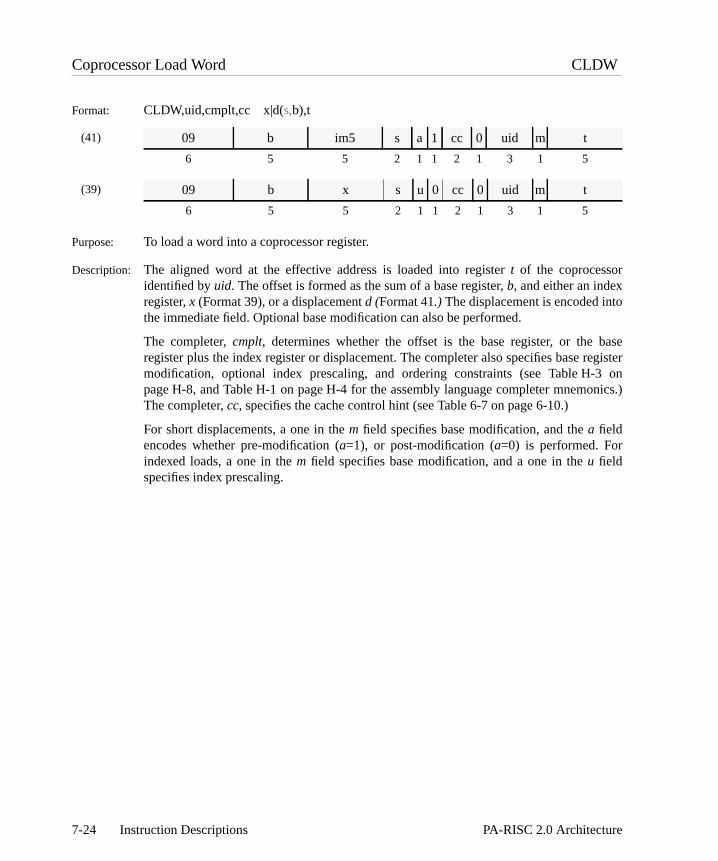
o
baseegister3 onnics.)
Coprocessor Load Word CLDW
Format: CLDW,uid,cmplt,cc x|d(s,b),t
(41)
(39)
Purpose: To load a word into a coprocessor register.
Description: The aligned word at the effective address is loaded into registert of the coprocessoridentified byuid. The offset is formed as the sum of a base register,b, and either an indexregister,x (Format 39), or a displacementd (Format 41.) The displacement is encoded intthe immediate field. Optional base modification can also be performed.
The completer,cmplt, determines whether the offset is the base register, or the register plus the index register or displacement. The completer also specifies base rmodification, optional index prescaling, and ordering constraints (see Table H-page H-8, and Table H-1 on page H-4 for the assembly language completer mnemoThe completer,cc, specifies the cache control hint (see Table 6-7 on page 6-10.)
For short displacements, a one in them field specifies base modification, and thea fieldencodes whether pre-modification (a=1), or post-modification (a=0) is performed. Forindexed loads, a one in them field specifies base modification, and a one in theu fieldspecifies index prescaling.
09 b im5 s a 1 cc 0 uid m t
6 5 5 2 1 1 2 1 3 1 5
09 b x s u 0 cc 0 uid m t
6 5 5 2 1 1 2 1 3 1 5
7-24 Instruction Descriptions PA-RISC 2.0 Architecture

Operation: if (indexed_load) /* indexed (Format 39)*/switch (cmplt) {
case S:case SM: dx← lshift(GR[x],2);
break;case M:default: dx← GR[x];
break;}
} else /* short displacement */dx ← low_sign_ext(im5,5); /* (Format 41) */
space← space_select(s,GR[b],format);switch (cmplt) {
case MB: offset← GR[b] + dx;GR[b] ← GR[b] + dx;break;
case MA:case M:case SM: offset← GR[b];
GR[b] ← GR[b] + dx;break;
default: offset← GR[b] + dx;break;
}send_to_copr(uid,t);CPR[uid][t] ← mem_load(space,offset,0,31,cc);if (cmplt == O)
enforce_ordered_load;
Exceptions: Assist exception trap Unaligned data reference trapData TLB miss fault/data page fault Page reference trapData memory access rights trap Assist emulation trapData memory protection ID trap
Restrictions: If the completerO is specified, the displacement must be 0.
7-25PA-RISC 2.0 Architecture Instruction Descriptions

tries.
get
Clear Branch Target Stack CLRBTS
Format: CLRBTS
(23)
Purpose: To clear the branch target stack.
Description: The branch target stack is cleared, either by making it empty or by invalidating all en
If this instruction is nullified, the results are undefined.
This instruction is executed as aNOP on machines that do not implement the branch tarstack.
Operation: clear_BTS();
Exceptions: none
3A 0 0 2 0 0 1 0 1
6 5 5 3 1 9 1 1 1
7-26 Instruction Descriptions PA-RISC 2.0 Architecture

the
n,
arget,
isch is.
n inn in
D-3),7 forr theer isn then and
Compare and Branch CMPB
Format: CMPB,cond,n r1,r2,target
(17)
Purpose: To compare two values and perform an IA-relative branch conditionally based onvalues compared.
Description: GR r1 is compared with GRr2. If the values compared satisfy the specified conditiocond, the word displacement is assembled from thew andw1 fields, sign extended, andadded to the current instruction offset plus 8 to form the target offset. The branch ttarget, in the assembly language format is encoded in thew andw1 fields.
If nullification is not specified, the following instruction is not nullified. If nullification specified, the instruction following a taken forward branch or a failing backward brannullified. The ,N completer, encoded in then field of the instruction, specifies nullification
Conditions: The condition,cond, can be any of the 32-bit compare or subtract conditions showTable D-3 on page D-4 or any of the 64-bit compare or subtract conditions showTable D-4 on page D-4 and is encoded in thec and opcode fields of the instruction.Opcode 20 is used for the 32-bit non-negated conditions (those with f = 0 in Tableopcode 22 for the 32-bit negated conditions (those with f = 1 in Table D-3), opcode 2the 64-bit non-negated conditions (those with f = 0 in Table D-4), and opcode 2F fo64-bit negated conditions (those with f = 1in Table D-4.) When a condition completnot specified, the “never” condition is used. The boolean variable “cond_satisfied” ioperation section is set to 1 when the values compared satisfy the specified conditioset to 0 otherwise.
Operation: GR[r1] + ∼GR[r2] + 1;disp ← lshift(sign_ext(assemble_12(w1,w),12),2);if (cond_satisfied)
IAOQ_Next ← IAOQ_Front + disp + 8;if (n)
if (disp < 0)PSW[N] ← !cond_satisfied;
elsePSW[N] ← cond_satisfied;
Exceptions: Taken branch trap
20/22/27/2F r2 r1 c w1 n w
6 5 5 3 11 1 1
7-27PA-RISC 2.0 Architecture Instruction Descriptions

ing
3 on4 on. Thepared
et
Compare and Clear CMPCLR
Format: CMPCLR,cond r1,r2,t
(8)
Purpose: To compare two registers, set a register to 0, and conditionally nullify the followinstruction, based on the result of the comparison.
Description: GR r1 and GRr2 are compared and GRt is set to zero. The following instruction isnullified if the values compared satisfy the specified condition,cond. The condition isencoded in thec, d, andf fields of the instruction.
Conditions: The condition is any of the 32-bit compare or subtract conditions shown in Table D-page D-4 or any of the 64-bit compare or subtract conditions shown in Table D-page D-4. When a condition completer is not specified, the "never" condition is usedboolean variable "cond_satisfied" in the operation section is set when the values comsatisfy the specified condition.
Operation: GR[r1] + ∼GR[r2] + 1;GR[t] ← 0;if (cond_satisfied) PSW[N]← 1;
Exceptions: None
Programming NoteCOMPARE AND CLEAR can be used to produce the logical value of the result of a comparison(assuming false is represented by 0 and true by 1) in a register. The following example will sra to 1 if rb andrc are equal, and to 0 if they are not equal:
02 r2 r1 c f 2 0 0 2 d t
6 5 5 3 1 2 1 1 2 1 5
CMPCLR,<> rb,rc,raLDO 1(0),ra
7-28 Instruction Descriptions PA-RISC 2.0 Architecture
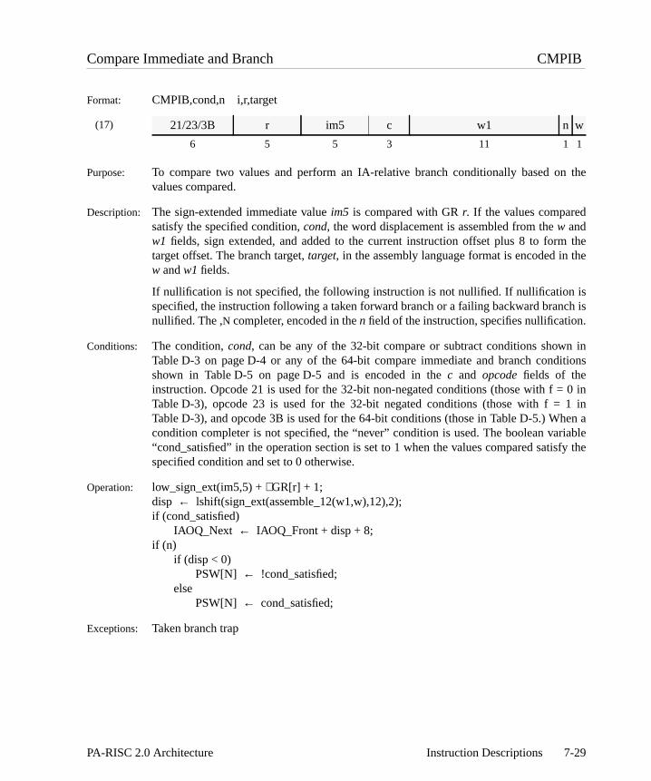
the
thethe
isch is.
n initions
0 in1 inen aiablefy the
Compare Immediate and Branch CMPIB
Format: CMPIB,cond,n i,r,target
(17)
Purpose: To compare two values and perform an IA-relative branch conditionally based onvalues compared.
Description: The sign-extended immediate valueim5 is compared with GRr. If the values comparedsatisfy the specified condition,cond, the word displacement is assembled from thew andw1 fields, sign extended, and added to the current instruction offset plus 8 to formtarget offset. The branch target,target, in the assembly language format is encoded in w andw1 fields.
If nullification is not specified, the following instruction is not nullified. If nullification specified, the instruction following a taken forward branch or a failing backward brannullified. The ,N completer, encoded in then field of the instruction, specifies nullification
Conditions: The condition,cond, can be any of the 32-bit compare or subtract conditions showTable D-3 on page D-4 or any of the 64-bit compare immediate and branch condshown in Table D-5 on page D-5 and is encoded in thec and opcode fields of theinstruction. Opcode 21 is used for the 32-bit non-negated conditions (those with f =Table D-3), opcode 23 is used for the 32-bit negated conditions (those with f = Table D-3), and opcode 3B is used for the 64-bit conditions (those in Table D-5.) Whcondition completer is not specified, the “never” condition is used. The boolean var“cond_satisfied” in the operation section is set to 1 when the values compared satisspecified condition and set to 0 otherwise.
Operation: low_sign_ext(im5,5) +∼GR[r] + 1;disp ← lshift(sign_ext(assemble_12(w1,w),12),2);if (cond_satisfied)
IAOQ_Next ← IAOQ_Front + disp + 8;if (n)
if (disp < 0)PSW[N] ← !cond_satisfied;
elsePSW[N] ← cond_satisfied;
Exceptions: Taken branch trap
21/23/3B r im5 c w1 n w
6 5 5 3 11 1 1
7-29PA-RISC 2.0 Architecture Instruction Descriptions

0, and
3 on4 on. Thepared
Compare Immediate and Clear CMPICLR
Format: CMPICLR,cond i,r,t
(9)
Purpose: To compare an immediate value with the contents of a register, set a register to conditionally nullify the following instruction.
Description: The sign-extended immediate and GRr are compared and GRt is set to zero. Theimmediate value is encoded into theim11 field. The following instruction is nullified if thevalues compared satisfy the specified condition,cond. The condition is encoded in thec,d, andf fields of the instruction.
Conditions: The condition is any of the 32-bit compare or subtract conditions shown in Table D-page D-4 or any of the 64-bit compare or subtract conditions shown in Table D-page D-4. When a condition completer is not specified, the "never" condition is usedboolean variable "cond_satisfied" in the operation section is set when the values comsatisfy the specified condition.
Operation: low_sign_ext(im11,11) +∼GR[r] + 1;GR[t] ← 0;if (cond_satisfied) PSW[N]← 1;
Exceptions: None
24 r t c f d im11
6 5 5 3 1 1 11
7-30 Instruction Descriptions PA-RISC 2.0 Architecture

nified.
romdent
ion of trap is
unitin the
ed in
Coprocessor Operation COPR
Format: COPR,uid,sop,n
(38)
Purpose: To invoke a coprocessor unit operation.
Description: The coprocessor operation codesop (assembled from thesop1 andsop2 fields) is sent tothe coprocessor identified byuid and the indicated operation is performed. If nullificatiois specified and the coprocessor condition is satisfied, the following instruction is null
Operation: sop ← cat(sop1,sop2);coprocessor_op(uid,sop,n,IAOQ_Front{30..31});if (n && coprocessor_condition(uid,sop,n))
PSW[N] ← 1;
Exceptions: Assist emulation trap Assist exception trap
Notes: The COPROCESSOR OPERATION instruction is used to implement theIDENTIFYCOPROCESSOR pseudo-operation. This operation places an identification number fthe coprocessoruid into coprocessor register 0. This value is implementation depenand is useful for configuration, diagnostic, and error recovery.
Each implementation must choose an identification number that identifies the versthe coprocessor. The values all zeros and all ones are reserved. An assist exceptionnot allowed and this instruction must be implemented by all coprocessors withidentifiers 4 through 7. Unit identifiers 0 and 2 have a uid-specific sequence to obtaidentification number.
The format of the identification number for the floating-point coprocessor is describ“Floating-Point Status Register” on page 8-8.
TheIDENTIFY COPROCESSOR pseudo-operation is coded as follows:COPR,uid,0
0C sop1 uid n sop2
6 17 3 1 5
7-31PA-RISC 2.0 Architecture Instruction Descriptions

e
to
baseegister3 onnics.)
Coprocessor Store Doubleword CSTD
Format: CSTD,uid,cmplt,cc r,x|d(s,b)
(42)
(40)
Purpose: To store a doubleword from a coprocessor register.
Description: Registerr of the coprocessor identified byuid is stored in the aligned doubleword at theffective address. The offset is formed as the sum of a base register,b, and either an indexregister,x (Format 40), or a displacementd (Format 42.) The displacement is encoded inthe immediate field. Optional base modification can also be performed.
The completer,cmplt, determines whether the offset is the base register, or the register plus the index register or displacement. The completer also specifies base rmodification, optional index prescaling, and ordering constraints (see Table H-page H-8, and Table H-1 on page H-4 for the assembly language completer mnemoThe completer,cc, specifies the cache control hint (see Table 6-8 on page 6-10.)
For short displacements, a one in them field specifies base modification, and thea fieldencodes whether pre-modification (a=1), or post-modification (a=0) is performed. Forindexed stores, a one in them field specifies base modification, and a one in theu fieldspecifies index prescaling.
0B b im5 s a 1 cc 1 uid m r
6 5 5 2 1 1 2 1 3 1 5
0B b x s u 0 cc 1 uid m r
6 5 5 2 1 1 2 1 3 1 5
7-32 Instruction Descriptions PA-RISC 2.0 Architecture

Operation: if (indexed_store) /* indexed (Format 40)*/switch (cmplt) {
case S:case SM: dx← lshift(GR[x],3);
break;case M:default: dx← GR[x];
break;}
} else /* short displacement */dx ← low_sign_ext(im5,5); /* (Format 42) */
space← space_select(s,GR[b],format);if (cmplt == O)
enforce_ordered_store;switch (cmplt) {
case MB: offset← GR[b] + dx;GR[b] ← GR[b] + dx;break;
case MA:case M:case SM: offset← GR[b];
GR[b] ← GR[b] + dx;break;
default: offset← GR[b] + dx;break;
}send_to_copr(uid,r); mem_store(space,offset,0,63,cc,CPR[uid][r]);
Exceptions: Assist exception trap TLB dirty bit trapData TLB miss fault/data page fault Page reference trapData memory access rights trap Unaligned data reference trapData memory protection ID trap Assist emulation trap
Restrictions: If the completerO is specified, the displacement must be 0.
7-33PA-RISC 2.0 Architecture Instruction Descriptions

e
he
baseegister3 onnics.)
Coprocessor Store Word CSTW
Format: CSTW,uid,cmplt,cc r,x|d(s,b)
(42)
(40)
Purpose: To store a word from a coprocessor register.
Description: Registerr of the coprocessor identified byuid is stored in the aligned word at the effectivaddress. The offset is formed as the sum of a base register,b, and either an index register,x(Format 40), or a displacementd (Format 42.) The displacement is encoded into timmediate field. Optional base modification can also be performed.
The completer,cmplt, determines whether the offset is the base register, or the register plus the index register or displacement. The completer also specifies base rmodification, optional index prescaling, and ordering constraints (see Table H-page H-8, and Table H-1 on page H-4 for the assembly language completer mnemoThe completer,cc, specifies the cache control hint (see Table 6-8 on page 6-10.)
For short displacements, a one in them field specifies base modification, and thea fieldencodes whether pre-modification (a=1), or post-modification (a=0) is performed. Forindexed stores, a one in them field specifies base modification, and a one in theu fieldspecifies index prescaling.
09 b im5 s a 1 cc 1 uid m r
6 5 5 2 1 1 2 1 3 1 5
09 b x s u 0 cc 1 uid m r
6 5 5 2 1 1 2 1 3 1 5
7-34 Instruction Descriptions PA-RISC 2.0 Architecture
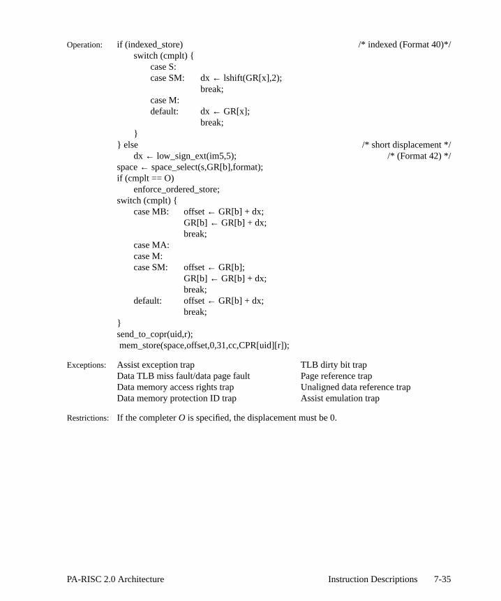
Operation: if (indexed_store) /* indexed (Format 40)*/switch (cmplt) {
case S:case SM: dx← lshift(GR[x],2);
break;case M:default: dx← GR[x];
break;}
} else /* short displacement */dx ← low_sign_ext(im5,5); /* (Format 42) */
space← space_select(s,GR[b],format);if (cmplt == O)
enforce_ordered_store;switch (cmplt) {
case MB: offset← GR[b] + dx;GR[b] ← GR[b] + dx;break;
case MA:case M:case SM: offset← GR[b];
GR[b] ← GR[b] + dx;break;
default: offset← GR[b] + dx;break;
}send_to_copr(uid,r); mem_store(space,offset,0,31,cc,CPR[uid][r]);
Exceptions: Assist exception trap TLB dirty bit trapData TLB miss fault/data page fault Page reference trapData memory access rights trap Unaligned data reference trapData memory protection ID trap Assist emulation trap
Restrictions: If the completerO is specified, the displacement must be 0.
7-35PA-RISC 2.0 Architecture Instruction Descriptions

s, isnal
ified
-8itioniablees the
Decimal Correct DCOR
Format: DCOR,cmplt,cond r,t
(8)
Purpose: To separately correct the 16 BCD digits of the result of an addition or subtraction.
Description: A decimal correction value, computed from the 4-bit carries in the PSW C/B bitcombined with GRr, and the result is placed in GRt. The correction can be either aintermediate correction (cmplt == I), which leaves the result pre-biased, or a fincorrection (nocmplt), which removes the pre-bias. This is encoded in thee1 field (e1=3for intermediate correction,e1=2 for final correction.)
For intermediate correction, every digit of GRr corresponding to a bit which is 1 in thePSW C/B-bits has 6 added to it. For final correction, every digit of GRr corresponding toa bit which is 0 in the PSW C/B-bits has 6 subtracted from it.
The following instruction is nullified if the result of the operation satisfies the specconditioncond. The condition is encoded in thec, d, andf fields of the instruction.
Conditions: The conditioncond is any of the 32-bit unit conditions shown in Table D-11 on page Dor any of the 64-bit unit conditions shown in Table D-12 on page D-8. When a condcompleter is not specified, the "never" condition is used. The boolean var"cond_satisfied" in the operation section is set when the result of the operation satisfispecified condition.
02 r 0 c f 2 1 1 e1 d t
6 5 5 3 1 2 1 1 2 1 5
7-36 Instruction Descriptions PA-RISC 2.0 Architecture

Operation: if (cmplt == I)GR[t] ← GR[r] + cat(
0x6*PSW[C/B]{0}, 0x6*PSW[C/B]{1},0x6*PSW[C/B]{2}, 0x6*PSW[C/B]{3},0x6*PSW[C/B]{4}, 0x6*PSW[C/B]{5},0x6*PSW[C/B]{6}, 0x6*PSW[C/B]{7},0x6*PSW[C/B]{8}, 0x6*PSW[C/B]{9},0x6*PSW[C/B]{10}, 0x6*PSW[C/B]{11},0x6*PSW[C/B]{12}, 0x6*PSW[C/B]{13},0x6*PSW[C/B]{14}, 0x6*PSW[C/B]{15});
elseGR[t] ← GR[r] - cat(
0x6*(1 - PSW[C/B]{0}), 0x6*(1 - PSW[C/B]{1}),0x6*(1 - PSW[C/B]{2}), 0x6*(1 - PSW[C/B]{3}),0x6*(1 - PSW[C/B]{4}), 0x6*(1 - PSW[C/B]{5}),0x6*(1 - PSW[C/B]{6}), 0x6*(1 - PSW[C/B]{7}),0x6*(1 - PSW[C/B]{8}), 0x6*(1 - PSW[C/B]{9}),0x6*(1 - PSW[C/B]{10}), 0x6*(1 - PSW[C/B]{11}),0x6*(1 - PSW[C/B]{12}), 0x6*(1 - PSW[C/B]{13}),0x6*(1 - PSW[C/B]{14}), 0x6*(1 - PSW[C/B]{15}));
if (cond_satisfied) PSW[N]← 1;
Exceptions: None
Programming NoteDECIMAL CORRECT can be used to take the sum of 64-bit BCD values.ra, rb, rc, andrd eachcontain a 64-bit BCD value andrt will hold the result at the end of the sequence. TheUADDCMoperation is used to pre-bias the value inra in order to perform BCD arithmetic. TheDCOR,Ioperations between theADD operations are used to re-adjust the BCD bias of the result. Thefinal DCOR operation is used to remove the bias and leave the value inrt in BCD format. Forthe following example, the registernines contains the value 0x99999999 99999999.
UADDCM ra,nines,rt ; pre-bias first operandADD rt,rb,rt ; add in the next valueDCOR,I rt,rt ; correct result, retaining biasADD rt,rc,rt ; add in the next valueDCOR,I rt,rt ; correct result, retaining biasADD rt,rd,rt ; add in the next valueDCOR rt,rt ; final correction
7-37PA-RISC 2.0 Architecture Instruction Descriptions

ullify
AR,d forif thes ared the
thenics.)is
The
by
Deposit Doubleword DEPD
Format: DEPD,cmplt,cond r,pos,len,t
(13)
(16)
Purpose: To deposit a value into a register at a fixed or variable position, and conditionally nthe following instruction.
Description: A right-justified field from GRr is deposited (merged) into GRt. The field begins at thebit position given bypos and extendslen bits to the left. The remainder of GRt isoptionally zeroed or left unchanged.
The bit position,pos, can either be a constant (specifying a fixed deposit), or can be Sthe Shift Amount Register (CR 11) (specifying a variable deposit.) Format 13 is usevariable deposits; Format 16 is used for fixed deposits. For variable deposits, deposited field extends beyond the leftmost bit, it is truncated and the higher bitignored. For fixed deposits, it is an undefined operation for the field to extend beyonleftmost bit.
The completer,cmplt, determines whether or not the target register is zeroed beforefield is deposited into it. (Table 7-1 defines the assembly language completer mnemoThis is encoded in thenz field of the instruction, with 0 indicating that the register zeroed and 1indicating that it is not.
The following diagram illustrates a fixed deposit of a 50-bit field at bit position 56. instruction is: DEPD r,56,50,t.
The lengthlen in the assembly language format is encoded into thecl andclen fields. Forfixed deposits, the bit positionpos in the assembly language format is represented
35 t r c 0 nz 1 cl 0 clen
6 5 5 3 2 1 1 1 3 5
3C t r c cl cpnz cpos clen
6 5 5 3 1 1 1 5 5
Table 7-1. Deposit Instruction Completers
cmplt Description nz
<none> value is deposited into the old value of the target register 1
Z value is deposited into a field of zeros 0
7 56
6314
63
GR r:
GR t:
0
0
7-38 Instruction Descriptions PA-RISC 2.0 Architecture

ified
on. Theof the
/
4-sa,t
cat(cp,cpos) in the machine instruction, whose value is 63–pos.
The following instruction is nullified if the result of the operation satisfies the speccondition,cond. The condition is encoded in thec field of the instruction.
Conditions: The condition is any of the 64-bit extract/deposit conditions shown in Table D-14page D-9. When a condition completer is not specified, the "never" condition is usedboolean variable "cond_satisfied" in the operation section is set when the result operation satisfies the specified condition.
Operation: len ← assemble_6(cl,clen)if (fixed_deposit) { /* (Format 16) */
if (pos >= len–1)tpos ← pos;
elseundefined;
} else /* (Format 13) */tpos ← CR[11];
if (cmplt == Z) /* nz=0 */GR[t] ← 0;
if (tpos–len+1< 0) /* field extends beyond leftmost bit *GR[t]{0..tpos} ← GR[r]{63–tpos..63};
elseGR[t]{tpos–len+1..tpos}← GR[r]{64–len..63};
if (cond_satisfied) PSW[N]← 1;
Exceptions: None
Restrictions: Since for fixed deposits, the deposited field is fully specified bylen and pos, it is anundefined operation if the field extends beyond the leftmost bit.
Notes: The SHLD,cond r,sa,t pseudo-operation generates a DEPD,Z,cond r,63-sa,6instruction to perform a shift left by sa bits on the doubleword in general register r.
7-39PA-RISC 2.0 Architecture Instruction Descriptions

and
AR,d forif thes ared the
thepleter
t bit
by
ified
on
Deposit Doubleword Immediate DEPDI
Format: DEPDI,cmplt,cond i,pos,len,t
(13)
(16)
Purpose: To deposit an immediate value into a register at a fixed or variable position,conditionally nullify the following instruction.
Description: A right-justified field from the sign-extended immediatei is deposited (merged) into GRt.The field begins at the bit position given bypos and extendslen bits to the left. Theremainder of GRt is optionally zeroed or left unchanged.
The bit position,pos, can either be a constant (specifying a fixed deposit), or can be Sthe Shift Amount Register (CR 11) (specifying a variable deposit.) Format 13 is usevariable deposits; Format 16 is used for fixed deposits. For variable deposits, deposited field extends beyond the leftmost bit, it is truncated and the higher bitignored. For fixed deposits, it is an undefined operation for the field to extend beyonleftmost bit.
The completer,cmplt, determines whether or not the target register is zeroed beforefield is deposited into it (see Table 7-1 on page 7-38 for the assembly language commnemonics.) This is encoded in thenz field of the instruction, with 0 indicating that theregister is zeroed and 1indicating that it is not.
The following diagram illustrates a fixed deposit of the value 0x9 into a 50-bit field aposition 56. The instruction is: DEPDI 0x9,56,50,t.
The lengthlen in the assembly language format is encoded into thecl andclen fields. Forfixed deposits, the bit positionpos in the assembly language format is representedcat(cp,cpos) in the machine instruction, whose value is 63–pos. The immediate is encodedin theim5 field of the instruction.
The following instruction is nullified if the result of the operation satisfies the speccondition,cond. The condition is encoded in thec field of the instruction.
Conditions: The condition is any of the 64-bit extract/deposit conditions shown in Table D-14
35 t im5 c 2 nz 1 cl 0 clen
6 5 5 3 2 1 1 1 3 5
3D t im5 c cl cpnz cpos clen
6 5 5 3 1 1 1 5 5
7 56
6314
63
i:
GR t:
0
0
0x9
0x9
7-40 Instruction Descriptions PA-RISC 2.0 Architecture
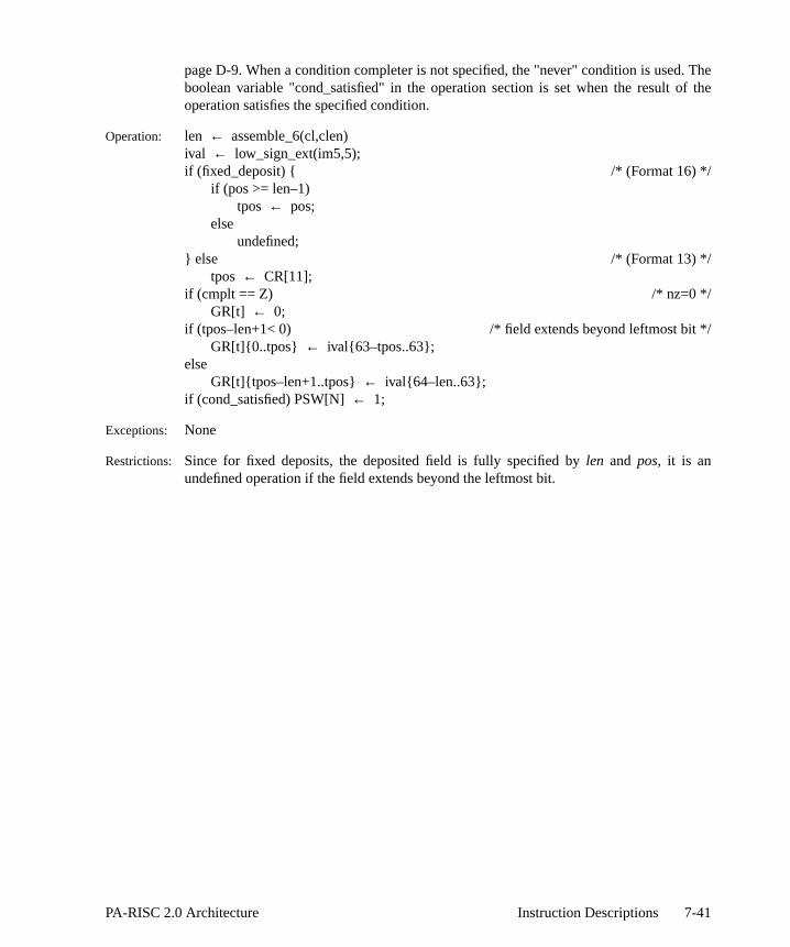
. Theof the
/
page D-9. When a condition completer is not specified, the "never" condition is usedboolean variable "cond_satisfied" in the operation section is set when the result operation satisfies the specified condition.
Operation: len ← assemble_6(cl,clen)ival ← low_sign_ext(im5,5);if (fixed_deposit) { /* (Format 16) */
if (pos >= len–1)tpos ← pos;
elseundefined;
} else /* (Format 13) */tpos ← CR[11];
if (cmplt == Z) /* nz=0 */GR[t] ← 0;
if (tpos–len+1< 0) /* field extends beyond leftmost bit *GR[t]{0..tpos} ← ival{63–tpos..63};
elseGR[t]{tpos–len+1..tpos}← ival{64–len..63};
if (cond_satisfied) PSW[N]← 1;
Exceptions: None
Restrictions: Since for fixed deposits, the deposited field is fully specified bylen and pos, it is anundefined operation if the field extends beyond the leftmost bit.
7-41PA-RISC 2.0 Architecture Instruction Descriptions

, and
AR,d forftmostfixeded theld to
thepleter
unt
ified
Deposit Word DEPW
Format: DEPW,cmplt,cond r,pos,len,t
(13)
(16)
Purpose: To deposit a value into the rightmost 32 bits of a register at a fixed or variable positionconditionally nullify the following instruction.
Description: A right-justified field from GRr is deposited (merged) into the rightmost 32 bits of GRt.The field begins at the bit position given bypos+32 and extendslen bits to the left. Theremainder of GRt is optionally zeroed or left unchanged. The leftmost 32 bits of GRt areundefined.
The bit position,pos, can either be a constant (specifying a fixed deposit), or can be Sthe Shift Amount Register (CR 11) (specifying a variable deposit.) Format 13 is usevariable deposits; Format 16 is used for fixed deposits. For variable deposits, the lebit of the SAR is ignored, and 32 is added to the value in the lower 5 bits. For deposits, 32 is added to thepos value in the instruction. For variable deposits, if thdeposited field extends beyond the leftmost bit (of the rightmost 32), it is truncated anhigher bits are ignored. For fixed deposits, it is an undefined operation for the fieextend beyond the leftmost bit (of the rightmost 32.)
The completer,cmplt, determines whether or not the target register is zeroed beforefield is deposited into it (see Table 7-1 on page 7-38 for the assembly language commnemonics.) This is encoded in thenz field of the instruction, with 0 indicating that theregister is zeroed and 1indicating that it is not.
The following diagram illustrates a deposit of a 10-bit field when the Shift AmoRegister contains the value 24. The instruction is: DEPW r,sar,10,t.
The lengthlen in the assembly language format is encoded into theclen field. For fixeddeposits, the bit positionpos in the assembly language format is represented bycpos in themachine instruction, whose value is 31–pos.
The following instruction is nullified if the result of the operation satisfies the spec
35 t r c 0 nz 0 0 0 clen
6 5 5 3 2 1 1 1 3 5
35 t r c 0 1 nz cpos clen
6 5 5 3 1 1 1 5 5
32
47 56
63
32
54
63
GR r:
GR t:
0
0
undefined
7-42 Instruction Descriptions PA-RISC 2.0 Architecture

on. Theof the
/
2-sa,t
condition,cond. The condition is encoded in thec field of the instruction.
Conditions: The condition is any of the 32-bit extract/deposit conditions shown in Table D-13page D-9. When a condition completer is not specified, the "never" condition is usedboolean variable "cond_satisfied" in the operation section is set when the result operation satisfies the specified condition.
Operation: len ← assemble_6(0,clen);if (fixed_deposit) { /* (Format 16) */
if (pos >= len–1)tpos ← pos + 32;
elseundefined;
} else /* (Format 13) */tpos ← CR[11]{1..5} + 32;
if (cmplt == Z) /* nz=0 */GR[t]{32..63} ← 0;
if (tpos–len+1< 32) /* field extends beyond leftmost bit *GR[t]{32..tpos} ← GR[r]{95–tpos..63};
elseGR[t]{tpos–len+1..tpos}← GR[r]{64–len..63};
GR[t]{0..31} ← undefined;if (cond_satisfied) PSW[N]← 1;
Exceptions: None
Restrictions: Since for fixed deposits, the deposited field is fully specified bylen and pos, it is anundefined operation if the field extends beyond the leftmost bit (of the rightmost 32.)
Notes: The SHLW,cond r,sa,t pseudo-operation generates a DEPW,Z,cond r,31-sa,3instruction to perform a shift left by sa bits on the word in general register r.
7-43PA-RISC 2.0 Architecture Instruction Descriptions
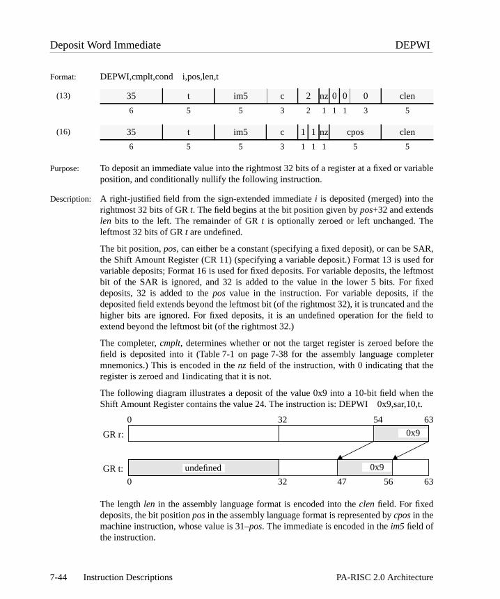
riable
e
AR,d forftmostfixeded theld to
thepleter
the,t.
Deposit Word Immediate DEPWI
Format: DEPWI,cmplt,cond i,pos,len,t
(13)
(16)
Purpose: To deposit an immediate value into the rightmost 32 bits of a register at a fixed or vaposition, and conditionally nullify the following instruction.
Description: A right-justified field from the sign-extended immediatei is deposited (merged) into therightmost 32 bits of GRt. The field begins at the bit position given bypos+32 and extendslen bits to the left. The remainder of GRt is optionally zeroed or left unchanged. Thleftmost 32 bits of GRt are undefined.
The bit position,pos, can either be a constant (specifying a fixed deposit), or can be Sthe Shift Amount Register (CR 11) (specifying a variable deposit.) Format 13 is usevariable deposits; Format 16 is used for fixed deposits. For variable deposits, the lebit of the SAR is ignored, and 32 is added to the value in the lower 5 bits. For deposits, 32 is added to thepos value in the instruction. For variable deposits, if thdeposited field extends beyond the leftmost bit (of the rightmost 32), it is truncated anhigher bits are ignored. For fixed deposits, it is an undefined operation for the fieextend beyond the leftmost bit (of the rightmost 32.)
The completer,cmplt, determines whether or not the target register is zeroed beforefield is deposited into it (Table 7-1 on page 7-38 for the assembly language commnemonics.) This is encoded in thenz field of the instruction, with 0 indicating that theregister is zeroed and 1indicating that it is not.
The following diagram illustrates a deposit of the value 0x9 into a 10-bit field whenShift Amount Register contains the value 24. The instruction is: DEPWI 0x9,sar,10
The lengthlen in the assembly language format is encoded into theclen field. For fixeddeposits, the bit positionpos in the assembly language format is represented bycpos in themachine instruction, whose value is 31–pos. The immediate is encoded in theim5 field ofthe instruction.
35 t im5 c 2 nz 0 0 0 clen
6 5 5 3 2 1 1 1 3 5
35 t im5 c 1 1 nz cpos clen
6 5 5 3 1 1 1 5 5
32
47 56
63
32
54
63
GR r:
GR t:
0
0
undefined
0x9
0x9
7-44 Instruction Descriptions PA-RISC 2.0 Architecture

ified
on. Theof the
/
The following instruction is nullified if the result of the operation satisfies the speccondition,cond. The condition is encoded in thec field of the instruction.
Conditions: The condition is any of the 32-bit extract/deposit conditions shown in Table D-13page D-9. When a condition completer is not specified, the "never" condition is usedboolean variable "cond_satisfied" in the operation section is set when the result operation satisfies the specified condition.
Operation: len ← assemble_6(0,clen);ival ← low_sign_ext(im5,5);if (fixed_deposit) { /* (Format 16) */
if (pos >= len–1)tpos ← pos + 32;
elseundefined;
} else /* (Format 13) */tpos ← CR[11]{1..5} + 32;
if (cmplt == Z) /* nz=0 */GR[t]{32..63} ← 0;
if (tpos–len+1< 32) /* field extends beyond leftmost bit *GR[t]{32..tpos} ← ival{95–tpos..63};
elseGR[t]{tpos–len+1..tpos}← ival{64–len..63};
GR[t]{0..31} ← undefined;if (cond_satisfied) PSW[N]← 1;
Exceptions: None
Restrictions: Since for fixed deposits, the deposited field is fully specified bylen and pos, it is anundefined operation if the field extends beyond the leftmost bit (of the rightmost 32.)
7-45PA-RISC 2.0 Architecture Instruction Descriptions

cular
mrged
Diagnose DIAG
Format: DIAG i
(28)
Purpose: To provide implementation-dependent operations for system initialization,reconfiguration, and diagnostic purposes.
Description: The immediate value in the assembly language is encoded in theim26 field of theinstruction. Refer to the hardware reference manual for the definition on a partimachine implementation.
Operation: if (priv != 0)privileged_operation_trap;
elseimplementation_dependent;
Exceptions: Privileged operation trapImplementation-dependent.
Restrictions: This instruction may be executed only at the most privileged level.
Notes: Since theDIAG instruction is privileged, a privileged operation trap will result frounprivileged diagnostic software executingDIAG. The trap could invoke an emulatowhich would allow the unprivileged software access to the required unprivileimplementation-dependent resources.
05 im26
6 26
7-46 Instruction Descriptions PA-RISC 2.0 Architecture

result
" inivide
ified
oweraryflowignedecial
3 on. Theof the
Divide Step DS
Format: DS,cond r1,r2,t
(8)
Purpose: To provide the primitive operation for integer division.
Description: This instruction performs a single-bit non-restoring divide step and produces a set ofconditions. It calculates one bit of the quotient when a 32-bit value in GRr1 is divided bya 32-bit value in GRr2 and leaves the partial remainder in GRt. The quotient bit is PSWC/B{8}. The carry/borrow bits in the PSW are updated. The variable "carry_borrowsthe operation section captures the 4-bit carries resulting from the single-bit doperation.
The following instruction is nullified if the result of the operation satisfies the speccondition,cond. The condition is encoded in thec andf fields of the instruction.
For this instruction, signed overflow condition means that the bit shifted out of the l32 bits differs from the leftmost bit of the lower 32 bits following the shift or an ordin32-bit signed overflow occurred during the addition or subtraction. Unsigned overmeans that the bit shifted out of the lower 32 bits is 1 or that an ordinary 32-bit unsoverflow occurred during the addition or subtraction. The conditions take on spinterpretations since the shift operation participates in overflow determination.
Conditions: The condition is any of the 32-bit compare or subtract conditions shown in Table D-page D-4. When a condition completer is not specified, the "never" condition is usedboolean variable "cond_satisfied" in the operation section is set when the result operation satisfies the specified condition.
Operation: if (PSW[V])GR[t] ← cat(lshift(GR[r1],1),PSW[C/B]{8}) +∼GR[r2] + 1;
elseGR[t] ← cat(lshift(GR[r1],1),PSW[C/B]{8}) + GR[r2];
PSW[C/B] ← carry_borrows;PSW[V] ← xor(carry_borrows{8},GR[r2]{32});if (cond_satisfied) PSW[N]← 1;
Exceptions: None
02 r2 r1 c f 1 0 0 1 0 t
6 5 5 3 1 2 1 1 2 1 5
7-47PA-RISC 2.0 Architecture Instruction Descriptions

ally
AR,d forracted is an
signhis ising
The
the
Extract Doubleword EXTRD
Format: EXTRD,cmplt,cond r,pos,len,t
(12)
(15)
Purpose: To extract any 64-bit or shorter field from a fixed or variable position, and conditionnullify the following instruction.
Description: A field is extracted from GRr, zero or sign extended and placed right-justified in GRt.The field begins at the bit position given bypos and extendslen bits to the left.
The bit position,pos, can either be a constant (specifying a fixed extract), or can be Sthe Shift Amount Register (CR 11) (specifying a variable extract.) Format 12 is usevariable extracts; Format 15 is used for fixed extracts. For variable extracts, if the extfield extends beyond the leftmost bit, it is zero or sign extended. For fixed extracts, itundefined operation for the field to extend beyond the leftmost bit.
The completer,cmplt, determines whether the extracted field is zero extended or extended. (Table 7-2 defines the assembly language completer mnemonics.) Tencoded in these field of the instruction, with 1 indicating sign extension and 0 indicatzero extension.
The following diagram illustrates a fixed extract of a 50-bit field at bit position 56. instruction is: EXTRD,U r,56,50,t.
The lengthlen in the assembly language format is encoded into thecl andclen fields. Forfixed extracts, the bit positionpos in the assembly language format is represented in machine instruction by cat(p,pos.)
34 r t c 2 se 1 cl 0 clen
6 5 5 3 2 1 1 1 3 5
36 r t c cl p se pos clen
6 5 5 3 1 1 1 5 5
Table 7-2. Extract Instruction Completers
cmplt Description se
<none> or S extracted value is sign extended 1
U extracted value is zero extended 0
7 56 63
14 63
GR r:
GR t:
0
0
7-48 Instruction Descriptions PA-RISC 2.0 Architecture
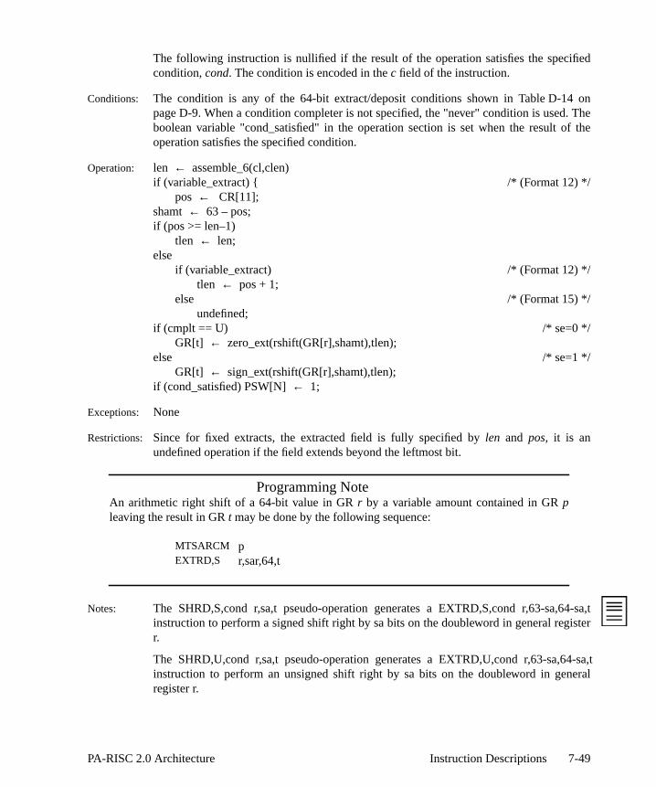
fied
f the
The following instruction is nullified if the result of the operation satisfies the specicondition, cond. The condition is encoded in thec field of the instruction.
Conditions: The condition is any of the 64-bit extract/deposit conditions shown in TableD-14 onpageD-9. When a condition completer is not specified, the "never" condition is used. Theboolean variable "cond_satisfied" in the operation section is set when the result ooperation satisfies the specified condition.
Operation: len ← assemble_6(cl,clen)if (variable_extract) { /* (Format 12) */
pos ← CR[11];shamt ← 63 – pos;if (pos >= len–1)
tlen ← len;else
if (variable_extract) /* (Format 12) */tlen ← pos + 1;
else /* (Format 15) */undefined;
if (cmplt == U) /* se=0 */GR[t] ← zero_ext(rshift(GR[r],shamt),tlen);
else /* se=1 */GR[t] ← sign_ext(rshift(GR[r],shamt),tlen);
if (cond_satisfied) PSW[N] ← 1;
Exceptions: None
Restrictions: Since for fixed extracts, the extracted field is fully specified by len and pos, it is anundefined operation if the field extends beyond the leftmost bit.
Programming NoteAn arithmetic right shift of a 64-bit value in GR r by a variable amount contained in GR pleaving the result in GR t may be done by the following sequence:
Notes: The SHRD,S,cond r,sa,t pseudo-operation generates a EXTRD,S,cond r,63-sa,64-sa,tinstruction to perform a signed shift right by sa bits on the doubleword in general registerr.
The SHRD,U,cond r,sa,t pseudo-operation generates a EXTRD,U,cond r,63-sa,64-sa,tinstruction to perform an unsigned shift right by sa bits on the doubleword in generalregister r.
MTSARCM pEXTRD,S r,sar,64,t
7-49PA-RISC 2.0 Architecture Instruction Descriptions

ally
d
AR,d fortmostfixedesign
nd the
signonics.) 0
hift
ified
Extract Word EXTRW
Format: EXTRW,cmplt,cond r,pos,len,t
(12)
(15)
Purpose: To extract any 32-bit or shorter field from a fixed or variable position, and conditionnullify the following instruction.
Description: A field is extracted from the rightmost 32 bits of GRr, zero or sign extended and placeright-justified in GRt. The field begins at the bit position given bypos+32 and extendslenbits to the left. The leftmost 32 bits of GRt are undefined.
The bit position,pos, can either be a constant (specifying a fixed extract), or can be Sthe Shift Amount Register (CR 11) (specifying a variable extract.) Format 12 is usevariable extracts; Format 15 is used for fixed extracts. For variable extracts, the lefbit of the SAR is ignored, and 32 is added to the value in the lower 5 bits. For extracts, 32 is added to thepos value in the instruction. For variable extracts, if thextracted field extends beyond the leftmost bit (of the rightmost 32), it is zero or extended. For fixed extracts, it is an undefined operation for the field to extend beyoleftmost bit (of the rightmost 32.)
The completer,cmplt, determines whether the extracted field is zero extended or extended (see Table 7-2 on page 7-48 for the assembly language completer mnemThis is encoded in these field of the instruction, with 1 indicating sign extension andindicating zero extension.
The following diagram illustrates a variable extract of a 10-bit field when the SAmount Register contains the value 24. The instruction is: EXTRW,U r,sar,10,t.
The lengthlen in the assembly language format is encoded into theclen field.
The following instruction is nullified if the result of the operation satisfies the speccondition,cond. The condition is encoded in thec field of the instruction.
34 r t c 2 se 0 0 0 clen
6 5 5 3 2 1 1 1 3 5
34 r t c 1 1 se pos clen
6 5 5 3 1 1 1 5 5
32 47 56 63
32 54 63
GR r:
GR t:
0
0
undefined
7-50 Instruction Descriptions PA-RISC 2.0 Architecture

f the
Conditions: The condition is any of the 32-bit extract/deposit conditions shown in TableD-13 onpageD-9. When a condition completer is not specified, the "never" condition is used. Theboolean variable "cond_satisfied" in the operation section is set when the result ooperation satisfies the specified condition.
Operation: len ← assemble_6(0,clen);if (variable_extract) { /* (Format 12) */
pos ← CR[11]{1..5};shamt ← 31 – pos;if (pos >= len–1)
tlen ← len;else
if (variable_extract) /* (Format 12) */tlen ← pos + 1;
else /* (Format 15) */undefined;
if (cmplt == U) /* se=0 */GR[t]{32..63} ← zero_ext(rshift(GR[r],shamt),tlen){32..63};
else /* se=1 */GR[t]{32..63} ← sign_ext(rshift(GR[r],shamt),tlen){32..63};
GR[t]{0..31} ← undefined;if (cond_satisfied) PSW[N] ← 1;
Exceptions: None
Restrictions: Since for fixed extracts, the extracted field is fully specified by len and pos, it is anundefined operation if the field extends beyond the leftmost bit (of the rightmost 32.)
Programming NoteAn arithmetic right shift of a 32-bit value in GR r by a variable amount contained in GR pleaving the result in GR t may be done by the following sequence:
Notes: The SHRW,S,cond r,sa,t pseudo-operation generates a EXTRW,S,cond r,31-sa,32-sa,tinstruction to perform a signed shift right by sa bits on the word in general register r.
The SHRW,U,cond r,sa,t pseudo-operation generates a EXTRW,U,cond r,31-sa,32-sa,tinstruction to perform an unsigned shift right by sa bits on the word in general register r.
MTSARCM pEXTRW,S r,sar,32,t
7-51PA-RISC 2.0 Architecture Instruction Descriptions

y theom
to.
base
embly
solute
ory
ches.
Flush Data Cache FDC
Format: FDC,cmplt x(s,b)FDC d(s,b)
(24)
(25)
Purpose: To invalidate a data cache line and write it back to memory if it is dirty.
Description: The data cache line (if present) specified by the effective address generated binstruction is written back to memory, if and only if it is dirty, and then invalidated frthe data cache. The offset is formed as the sum of a base register,b, and either an indexregister,x (Format 24), or a displacementd (Format 25.) The displacement is encoded inthe im5 field. Optional base modification can also be performed with the indexed form
The completer,cmplt, determines whether the offset is the base register, or the register plus the index register or displacement. The completer, encoded in them-field ofthe instruction, also specifies base register modification. (Table 7-3 defines the asslanguage completer mnemonics.)
Table 7-3. System Control Instruction Completers
The PSW D-bit (Data address translation enable) determines whether a virtual or abaddress is used.
A cache line is calleddirty if any byte has been written to since it was read from memor if a STBY,E to the leftmost byte of a word has been performed.
In a multiprocessor system, a flush request is broadcast to all data and combined ca
Operation: space← space_select(s,GR[b],format);if (indexed_load) /* indexed (Format 24)*/
switch (cmplt) {case M: offset← GR[b];
GR[b] ← GR[b] + GR[x];break;
default: offset← GR[b] + GR[x];break;
}
01 b x s 4A m rv
6 5 5 2 8 1 5
01 b im5 s CA 0 rv
6 5 5 2 8 1 5
cmplt Description m
<none> don’t modify base register 0M Modify base register 1
7-52 Instruction Descriptions PA-RISC 2.0 Architecture

/
ta and
eringons
else /* short displacement (Format 25)*offset← GR[b] + low_sign_ext(im5,5); /* (new) */
Dcache_flush(space,offset);
Exceptions: Non-access data TLB miss fault
Notes: For systems that do not have a cache, this instruction executes as a null instruction.
In systems with a combined cache, this instruction may be used to flush both dainstruction lines from the cache.
This instruction may be executed out of sequence but must satisfy the instruction ordconstraints. TheSYNC instruction enforces program order with respect to the instructifollowing theSYNC.
It is an undefined operation to execute anFDC with a nonzeros-field at a nonzero privilegelevel when the PSW W-bit is 1.
7-53PA-RISC 2.0 Architecture Instruction Descriptions

cache
f the are
resspleter
data
. This
Flush Data Cache Entry FDCE
Format: FDCE,cmplt x(s,b)
(24)
Purpose: To provide for flushing the entire data or combined cache by causing zero or more lines to be invalidated.
Description: Zero or more cache lines specified by an implementation-dependent function oeffective address are written back to main memory, if and only if they are dirty, andinvalidated in the data or combined cache. The completer,cmplt, determines if the offset isthe base register,b, or the base register plus the index registerx. The completer, encodedin the m-field of the instruction, specifies base register modification. No addtranslation is performed (see Table 7-3 on page 7-52 for the assembly language commnemonics.)
When this instruction is used in an architecturally defined cache flush loop, the entireor combined cache will be flushed upon completion of the loop.
Operation: space← space_select(s,GR[b],INDEXED);switch (cmplt) {
case M: offset← GR[b]; /*m=1*/GR[b] ← GR[b] + GR[x];break;
default: offset← GR[b] + GR[x]; /*m=0*/break;
}Dcache_flush_entries(space,offset);
Exceptions: None
Notes: In a multiprocessor system, this instruction is not broadcast to other processorsinstruction does not necessarily flush the entry specified by “space” and “offset”.
For systems that do not have a cache, this instruction executes as a null instruction.
It is an undefined operation to execute anFDCE with a nonzeros-field at a nonzeroprivilege level when the PSW W-bit is 1.
01 b x s 4B m rv
6 5 5 2 8 1 5
7-54 Instruction Descriptions PA-RISC 2.0 Architecture

y the
see
solute
lationsing a
bined
ction
Flush Instruction Cache FIC
Format: FIC,cmplt x(s|sr,b)
(26)
(24)
Purpose: To invalidate an instruction cache line.
Description: The instruction cache line (if any) specified by the effective address generated binstruction is invalidated in the instruction cache.The completer,cmplt, determines if theoffset is the base register,b, or the base register plus the index registerx. The completer,encoded in them-field of the instruction, also specifies base register modification (Table 7-3 on page 7-52 for the assembly language completer mnemonics.)
The space register,sr, is explicitly encoded in the 3-bits field of the instruction (Format26) or is implicitly specified by the 2-bits field of the instruction (Format 24.)
The PSW D-bit (Data address translation enable) determines whether a virtual or abaddress is used.
Either the instruction TLB or the data TLB can be used to perform the address transfor the address to be flushed. If the data TLB is used, a TLB miss fault is reported unon-access data TLB miss fault.
In a multiprocessor system, a flush request is broadcast to all instruction and comcaches.
Operation: if (explicit_pointer) /*(Format 26)*/space← SR[assemble_3(s)];
else /*(Format 24)*/space← space_select(s,GR[b],INDEXED);
switch (cmplt) {case M: offset← GR[b]; /*m=1*/
GR[b] ← GR[b] + GR[x];break;
default: offset← GR[b] + GR[x]; /*m=0*/break;
}Icache_flush(space,offset);
Exceptions: Non-access instruction TLB miss fault Non-access data TLB miss fault
Notes: For systems that do not have a cache, this instruction executes as a null instruction.
In systems with a combined cache, this instruction may be used to flush both instru
01 b x s 0A m rv
6 5 5 3 7 1 5
01 b x s 4F m 0
6 5 5 2 8 1 5
7-55PA-RISC 2.0 Architecture Instruction Descriptions

are
eringons
and data lines from the cache, including writing them back to main memory, if theydirty.
This instruction may be executed out of sequence but must satisfy the instruction ordconstraints. TheSYNC instruction enforces program order with respect to the instructifollowing theSYNC.
It is an undefined operation to execute an implicit-pointerFIC with a nonzeros-field at anonzero privilege level when the PSW W-bit is 1.
7-56 Instruction Descriptions PA-RISC 2.0 Architecture

more
f theFor
mory,
resspleter
ntire the flush
. This
n.
Flush Instruction Cache Entry FICE
Format: FICE,cmplt x(sr,b)
(26)
Purpose: To provide for flushing the entire instruction or combined cache by causing zero or cache lines to be invalidated.
Description: Zero or more cache lines specified by an implementation-dependent function oeffective address are invalidated in the instruction or combined cache. implementations with a combined cache, the cache lines are written back to main meif and only if they are dirty, and are invalidated. The completer,cmplt, determines if theoffset is the base register,b, or the base register plus the index registerx. The completer,encoded in them-field of the instruction, specifies base register modification. No addtranslation is performed (see Table 7-3 on page 7-52 for the assembly language commnemonics.) The space register,sr, is encoded in thes field of the instruction.
When this instruction is used in an architecturally defined cache flush loop, the einstruction or combined cache will be flushed upon completion of the loop (allcontents of the instruction cache, except the loop itself, prior to the beginning of theloop must be flushed.)
Operation: switch (cmplt) {case M: offset← GR[b]; /*m=1*/
GR[b] ← GR[b] + GR[x];break;
default: offset← GR[b] + GR[x]; /*m=0*/break;
}space← SR[assemble_3(s)];Icache_flush_entries(space,offset);
Exceptions: None
Notes: In a multiprocessor system, this instruction is not broadcast to other processorsinstruction does not necessarily flush the entry specified by “space” and “offset”.
For systems which do not have a cache, this instruction executes as a null instructio
01 b x s 0B m rv
6 5 5 3 7 1 5
7-57PA-RISC 2.0 Architecture Instruction Descriptions

lr the
. The
ed-
ignedumbers.s, are
Halfword Parallel Add HADD
Format: HADD,cmplt r1,r2,t
(8)
Purpose: To add multiple halfwords in parallel with optional saturation.
Description: The corresponding halfwords of GRr1 and GRr2 are added together in parallel. Optionasaturation is performed, which forces each halfword result to either the maximum ominimum value, if the result would have been out of the range of the target formathalfword results are placed in GRt.
The completer,cmplt, determines whether modular, signed-saturation, or unsignsaturation arithmetic is performed. The completer is encoded in thesat field of theinstruction. (Table 7-4 defines the assembly language completer mnemonics.) For ssaturation, all operands are treated as signed numbers, and the results are signed nFor unsigned saturation, the first operands, from GRr1, are treated as unsigned numberthe second operands, from GRr2, are treated as signed numbers, and the resultsunsigned numbers.
Operation: parallel for (start← 0; start <= 48; start += 16) {end← start + 15;GR[t]{start..end} ← (GR[r1]{start..end} + GR[r2]{start..end});switch (cmplt) {
case SS: if (maximum_signed_saturation) /*sat=1*/GR[t]{start..end}← 0x7FFF;
else if(minimum_signed_saturation)GR[t]{start..end}← 0x8000;
break;case US: if (maximum_unsigned_saturation) /*sat=0*/
GR[t]{start..end}← 0xFFFF;else if(minimum_unsigned_saturation)
GR[t]{start..end}← 0x0000;break;
default: /*sat=3*/break;
}}
Exceptions: None.
02 r2 r1 0 0 0 1 1 sat 0 t
6 5 5 3 1 2 1 1 2 1 5
Table 7-4. Halfword Arithmetic Completers
cmplt Description sat<none> modular arithmetic 3SS Signed Saturation 1US Unsigned Saturation 0
7-58 Instruction Descriptions PA-RISC 2.0 Architecture

isbit, to the
nding
Halfword Parallel Average HAVG
Format: HAVG r1,r2,t
(8)
Purpose: To average multiple halfwords in parallel.
Description: The corresponding halfwords of GRr1 and GRr2 are averaged in parallel. The averageobtained by adding the corresponding halfwords, and shifting the result right by one perform a divide by 2, with the halfword carry bit from the addition shifted back intoleftmost position of each result. The halfword results are placed in GRt.
Unbiased rounding is performed on the results to reduce the accumulation of rouerrors with cascaded operations.
Operation: parallel for (start← 0; start <= 48; start += 16){end ← start + 15;sum← GR[r1]{start..end} + GR[r2]{start..end};new_lsb← sum{14} | sum{15}; /*unbiased rounding*/GR[t]{start..end}← cat(carry,sum{0..13},new_lsb);
}
Exceptions: None
02 r2 r1 0 0 0 1 0 3 0 t
6 5 5 3 1 2 1 1 2 1 5
7-59PA-RISC 2.0 Architecture Instruction Descriptions

5,
Halfword Parallel Shift Left HSHL
Format: HSHL r,sa,t
(10)
Purpose: To perform multiple parallel halfword shift left operations.
Description: Each of the halfwords in GRr is shifted leftsa bits. The shift amount is between 0 and 1and is encoded in thesa field in the instruction. The halfword results are placed in GRt.
Operation: parallel for (start← 0; start <= 48; start += 16) {end← start + 15;GR[t]{start..end}← lshift(GR[r1]{start..end},sa);
}
Exceptions: None.
3E 0 r 1 0 0 2 sa 0 t
6 5 5 1 2 1 2 4 1 5
7-60 Instruction Descriptions PA-RISC 2.0 Architecture

nglt to. The in
Signed
e addigned
ble in
Halfword Parallel Shift Left and Add HSHLADD
Format: HSHLADD r1,sa,r2,t
(8)
Purpose: To perform multiple halfword shift left and add operations in parallel with saturation.
Description: Each halfword of GRr1 is shifted left bysa bits, and then added to the correspondihalfword of GRr2. Signed saturation is performed, which forces each halfword resueither the maximum or the minimum value, if the result would have been out of rangehalfword results are placed in GRt. The shift amount is either 1, 2, or 3, and is encodedthesa field of the instruction.
All operands are treated as signed numbers, and the results are signed numbers.saturation is performed.
For this instruction, signed saturation is based both on the shift operation and thoperation. That is, if the result of the shift operation is not representable in 16 bits, ssaturation occurs. If GRr1 was positive, maximum saturation occurs. If GRr2 wasnegative, minimum saturation occurs. If the result of the shift operation is representa16 bits, then saturation is determined by the add operation in the normal fashion.
Operation: parallel for (start← 0; start <= 48; start += 16) {end← start + 15;GR[t]{start..end}← lshift(GR[r1]{start..end},sa) + GR[r2]{start..end};if (maximum_signed_saturation)
GR[t]{start..end}← 0x7FFF;else if(minimum_signed_saturation)
GR[t]{start..end}← 0x8000;}
Exceptions: None
02 r2 r1 0 0 1 1 1 sa 0 t
6 5 5 3 1 2 1 1 2 1 5
7-61PA-RISC 2.0 Architecture Instruction Descriptions

.) The
Halfword Parallel Shift Right HSHR
Format: HSHR,cmplt r,sa,t
(10)
Purpose: To perform multiple parallel halfword signed or unsigned shift right operations.
Description: Each of the halfwords in GRr is shifted rightsa bits. The completer,cmplt, determineswhether a signed or unsigned shift is performed. The completer is encoded in these fieldof the instruction. (Table 7-5 defines the assembly language completer mnemonicsshift amount is between 0 and 15, and is encoded in thesa field in the instruction. Thehalfword results are placed in GRt.
Operation: parallel for (start← 0; start <= 48; start += 16) {end← start + 15;if (cmplt == U) /*se=2 (unsigned)*/
GR[t]{start..end}← rshift(GR[r1]{start..end},sa);else /*se=3 (signed)*/
GR[t]{start..end}← sign_ext_16(rshift(GR[r1]{start..end},sa),16–sa);}
Exceptions: None.
3E r 0 1 2 0 se sa 0 t
6 5 5 1 2 1 2 4 1 5
Table 7-5. Halfword Parallel Shift Right Completers
cmplt Description se
U Unsigned Shift 2
<none> or S Signed Shift 3
7-62 Instruction Descriptions PA-RISC 2.0 Architecture

.
ngedr the are
Signed
Halfword Parallel Shift Right and Add HSHRADD
Format: HSHRADD r1,sa,r2,t
(8)
Purpose: To perform multiple halfword shift right and add operations in parallel with saturation
Description: Each halfword of GRr1 is shifted right bysa bits, and then added to the correspondihalfword of GR r2. The bits shifted in equal the sign bit for each halfword. Signsaturation is performed, which forces each halfword result to either the maximum ominimum value, if the result would have been out of range. The halfword resultsplaced in GRt. The shift amount is either 1, 2, or 3, and is encoded in thesa field of theinstruction.
All operands are treated as signed numbers, and the results are signed numbers.saturation is performed.
Operation: parallel for (start← 0; start <= 48; start += 16) {end← start + 15;GR[t]{start..end}← sign_ext_16(rshift(GR[r1]{start..end},sa),16–sa) +
GR[r2]{start..end};if (maximum_signed_saturation)
GR[t]{start..end}← 0x7FFF;else if(minimum_signed_saturation)
GR[t]{start..end}← 0x8000;}
Exceptions: None.
02 r2 r1 0 0 1 0 1 sa 0 t
6 5 5 3 1 2 1 1 2 1 5
7-63PA-RISC 2.0 Architecture Instruction Descriptions

r thef the
ed-
onics.)ults are
nd
Halfword Parallel Subtract HSUB
Format: HSUB,cmplt r1,r2,t
(8)
Purpose: To subtract multiple halfwords in parallel with optional saturation.
Description: The corresponding halfwords of GRr2 are subtracted from the halfwords of GRr1 inparallel. Optional saturation is performed, which forces each halfword result to eithemaximum or the minimum value, if the result would have been out of the range otarget format. The halfword results are placed in GRt.
The completer,cmplt, determines whether modular, signed-saturation, or unsignsaturation arithmetic is performed. The completer is encoded in thesat field of theinstruction (see Table 7-4 on page 7-58 for the assembly language completer mnemFor signed saturation, all operands are treated as signed numbers, and the ressigned numbers. For unsigned saturation, the first operands, from GRr1, are treated asunsigned numbers, the second operands, from GRr2, are treated as signed numbers, athe results are unsigned numbers.
Operation: parallel for (start ← 0; start <= 48; start += 16) {end← start + 15;GR[t]{start..end} ← (GR[r1]{start..end} + ~GR[r2]{start..end} + 1);switch (cmplt) {
case SS: if (maximum_signed_saturation) /*sat=1*/GR[t]{start..end}← 0x7FFF;
else if(minimum_signed_saturation)GR[t]{start..end}← 0x8000;
break;case US: if (maximum_unsigned_saturation) /*sat=0*/
GR[t]{start..end}← 0xFFFF;else if(minimum_unsigned_saturation)
GR[t]{start..end}← 0x0000;break;
default: /*sat=3*/break;
}}
Exceptions: None.
02 r2 r1 0 0 0 0 1 sat 0 t
6 5 5 3 1 2 1 1 2 1 5
7-64 Instruction Descriptions PA-RISC 2.0 Architecture

ranges
er
Insert Data TLB Translation IDTLBT
Format: IDTLBT r1,r2
(26)
Purpose: To add an entry to the data TLB.
Description: A slot is found in the data or combined TLB and the new translation is placed there. If thedata or combined TLB already contains one or more entries whose virtual address overlap the virtual address range of the new translation, the old entries are removed. Thevirtual address is specified by the IOR and ISR control registers. The contents of the ISRare concatenated with the lower 32 bits of the IOR to form the virtual address. The upp32-bits of the IOR are ignored.
The physical address and the page size for the translation are specified by GR r1. The flagsand access control bits are specified by GR r2.
Operation: if (priv != 0)privileged_operation_trap;
else {space ← ISR;offset ← cat(ISR{32..63},IOR{32..63});page_size ← 4096 << (2 * GR[r1]{60..63});for (i ← 0; i < page_size/4096; i++) {
if (entry ← DTLB_search(space, offset + i*4096))DTLB_purge_local(entry);
}entry ← DTLB_alloc(space,offset);DTLB[entry].VIRTUAL_ADDR ← (space<<32) | (offset);DTLB[entry].PHY_PAGE_NO ← GR[r1]{7..58};DTLB[entry].PAGE_SIZE ← GR[r1]{60..63};DTLB[entry].ACCESS_RIGHTS ← GR[r2]{5..11};DTLB[entry].ACCESS_ID ← GR[r2]{32..62};DTLB[entry].T ← GR[r2]{2}DTLB[entry].D ← GR[r2]{3}DTLB[entry].B ← GR[r2]{4}DTLB[entry].U ← GR[r2]{12}DTLB[entry].O ← GR[r2]{13}if (combined_TLB) {
ITLB[entry].P ← GR[r2]{14}}
}
Exceptions: Privileged operation trap
01 r2 r1 0 60 0 0
6 5 5 3 7 1 5
7-65PA-RISC 2.0 Architecture Instruction Descriptions

into a
ueue
f the
Restrictions: This instruction may be executed only at the most privileged level.
Notes: This instruction may be used to insert both instruction entries and data entries combined TLB. The P bit is set to the appropriate bit of GRr in that case.
Note that no OR function is performed in creating the virtual address, since the IIA qalready contains a global address.
If smaller than 31-bit access IDs are implemented, only the appropriate number orightmost bits of GR[r]{32..62} are stored in the TLB.
7-66 Instruction Descriptions PA-RISC 2.0 Architecture

.rtual
tents
Insert Instruction TLB Translation IITLBT
Format: IITLBT r1,r2
(26)
Purpose: To add an entry to the instruction TLB.
Description: A slot is found in the instruction or combined TLB and the new translation is placed thereIf the instruction or combined TLB already contains one or more entries whose viaddress ranges overlap the virtual address range of the new translation, the old entries areremoved. The virtual address is specified by the front entry in the IIA queue. The conof the front element of the IIASQ are concatenated with the lower 32 bits of the frontelement of the IIAOQ to form the virtual address. The upper 32-bits of the IIAOQ areignored.
The physical address and the page size for the translation are specified by GR r1. The flagsand access control bits are specified by GR r2.
Operation: if (priv != 0)privileged_operation_trap;
else {space ← IIASQ_Front;offset ← cat(IIASQ_Front{32..63},IIAOQ_Front{32..63});page_size ← 4096 << (2 * GR[r1]{60..63});for (i ← 0; i < page_size/4096; i++) {
if (entry ← ITLB_search(space, offset + i*4096))ITLB_purge_local(entry);
}entry ← ITLB_alloc(space,offset);ITLB[entry].VIRTUAL_ADDR ← (space<<32) | (offset);ITLB[entry].PHY_PAGE_NO ← GR[r1]{7..58};ITLB[entry].PAGE_SIZE ← GR[r1]{60..63};ITLB[entry].ACCESS_RIGHTS ← GR[r2]{5..11};ITLB[entry].ACCESS_ID ← GR[r2]{32..62};ITLB[entry].P ← GR[r2]{14}
if (combined_TLB) {ITLB[entry].T ← GR[r2]{2}ITLB[entry].D ← GR[r2]{3}ITLB[entry].B ← GR[r2]{4}ITLB[entry].U ← GR[r2]{12}ITLB[entry].O ← GR[r2]{13}
}}
Exceptions: Privileged operation trap
01 r2 r1 0 20 0 0
6 5 5 3 7 1 5
7-67PA-RISC 2.0 Architecture Instruction Descriptions

into a
ueue
f the
Restrictions: This instruction may be executed only at the most privileged level.
Notes: This instruction may be used to insert both instruction entries and data entries combined TLB. The T, D, B, U, and O bits are set to the appropriate bits of GRr in thatcase.
Note that no OR function is performed in creating the virtual address, since the IIA qalready contains a global address.
If smaller than 31-bit access IDs are implemented, only the appropriate number orightmost bits of GR[r]{32..62} are stored in the TLB.
7-68 Instruction Descriptions PA-RISC 2.0 Architecture

the
d from
ed byI/Oing the be an
unless
e.
Load Coherence Index LCI
Format: LCI x(s,b),t
(24)
Purpose: To determine the coherence index corresponding to a virtual address.
Description: The effective address is calculated. GRt receives the coherence index corresponding to given virtual address.
In systems with separate data and instruction caches, the coherence index is obtainethe data cache.
The coherence index function is independent of the state of the PSW D-bit.
Operation: if (priv != 0)privileged_operation_trap;
else {space← space_select(s,GR[b],INDEXED);offset ← GR[b] + GR[x];GR[t] ← coherence_index(space,offset);
}
Exceptions: Privileged operation trap
Restrictions: This instruction may be executed only at the most privileged level.
Notes: All addresses within a page have the same coherence index.
The coherence index corresponding to a physical address can be determinperformingLCI on the equivalently-mapped virtual address. Also, in order to allow modules to have coherent access to equivalently-mapped addresses without knowcoherence index, the coherence index for equivalently-mapped addresses mustimplementation-defined function of the physical address bits only.
Two virtual addresses having the same coherence index are not guaranteed to aliasthey also meet the virtual aliasing rules.
For systems that do not have a cache, the target register receives an undefined valu
For system that do not support coherent I/O, this instruction is undefined.
01 b x s 4C 0 t
6 5 5 2 8 1 5
7-69PA-RISC 2.0 Architecture Instruction Descriptions
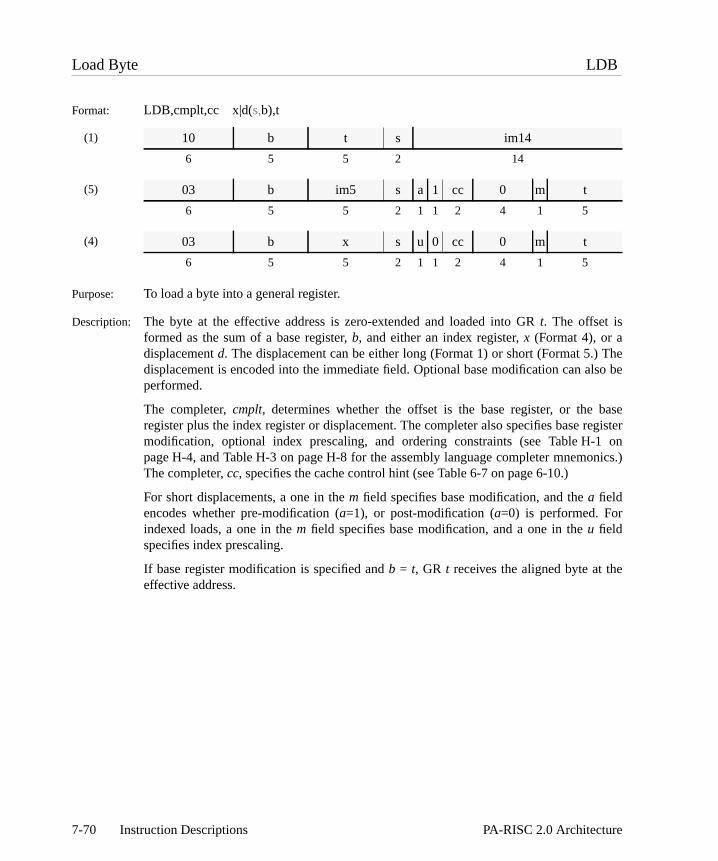
Thelso be
baseegister1 onnics.)
e
Load Byte LDB
Format: LDB,cmplt,cc x|d(s,b),t
(1)
(5)
(4)
Purpose: To load a byte into a general register.
Description: The byte at the effective address is zero-extended and loaded into GRt. The offset isformed as the sum of a base register,b, and either an index register,x (Format 4), or adisplacementd. The displacement can be either long (Format 1) or short (Format 5.)displacement is encoded into the immediate field. Optional base modification can aperformed.
The completer,cmplt, determines whether the offset is the base register, or the register plus the index register or displacement. The completer also specifies base rmodification, optional index prescaling, and ordering constraints (see Table H-page H-4, and Table H-3 on page H-8 for the assembly language completer mnemoThe completer,cc, specifies the cache control hint (see Table 6-7 on page 6-10.)
For short displacements, a one in them field specifies base modification, and thea fieldencodes whether pre-modification (a=1), or post-modification (a=0) is performed. Forindexed loads, a one in them field specifies base modification, and a one in theu fieldspecifies index prescaling.
If base register modification is specified andb = t, GR t receives the aligned byte at theffective address.
10 b t s im14
6 5 5 2 14
03 b im5 s a 1 cc 0 m t
6 5 5 2 1 1 2 4 1 5
03 b x s u 0 cc 0 m t
6 5 5 2 1 1 2 4 1 5
7-70 Instruction Descriptions PA-RISC 2.0 Architecture

/*/
Operation: if (indexed_load) /* indexed (Format 4)*/dx ← GR[x];
else if (d > 15 || d < -16) { /* long displacement *dx ← sign_ext(assemble_16(s,im14),16); /* (Format 1) cc ← NO_HINT;
} else /* short displacement */dx ← low_sign_ext(im5,5); /* (Format 5) */
space← space_select(s,GR[b],format);switch (cmplt) {
case MB: offset← GR[b] + dx;GR[b] ← GR[b] + dx;break;
case MA:case M:case SM: offset← GR[b];
GR[b] ← GR[b] + dx;break;
default: offset← GR[b] + dx;break;
}GR[t] ← zero_ext(mem_load(space,offset,0,17,cc),8);if (cmplt == O)
enforce_ordered_load;
Exceptions: Data TLB miss fault/data page fault Page reference trapData memory access rights trapData memory protection ID trap
Restrictions: If the completerO is specified, the displacement must be 0.
7-71PA-RISC 2.0 Architecture Instruction Descriptions

ster,
lso be
baseegister-3 on
of the
The
or is, thee
irty, orove or
cached into
leared
Load and Clear Doubleword LDCD
Format: LDCD,cmplt,cc x|d(s,b),t
(5)
(4)
Purpose: To read and lock a doubleword semaphore in main memory.
Description: The effective address is calculated. The offset is formed as the sum of a base regib,and either an index register,x (Format 4), or a displacementd (Format 5.) Thedisplacement is encoded into the immediate field. Optional base modification can aperformed.
The completer,cmplt, determines whether the offset is the base register, or the register plus the index register or displacement. The completer also specifies base rmodification, and optional index prescaling‘(see Table H-1 on page H-4, and Table Hpage H-8 for the assembly language completer mnemonics.) The completer,cc, specifiesthe cache control hint (see Table 6-9 on page 6-11.)
For short displacements, a one in them field specifies base modification, and thea fieldencodes whether pre-modification (a=1), or post-modification (a=0) is performed. Forindexed loads, a one in them field specifies base modification, and a one in theu fieldspecifies index prescaling. If base register modification is specified andb = t, the valueloaded is the aligned doubleword at the effective address.
The address must be 16-byte aligned. If the address is unaligned, the operation instruction is undefined.
The remaining steps of the instruction are indivisible and non-interruptible. semaphore operation is strongly ordered.
If a cache control hint is not specified, the instruction is performed as follows:
• If the cache line containing the effective address is not present in the cachepresent but not dirty, and the system is not fully coherent, the line is flushedaddressed doubleword is copied into GRt, and then set to zero in memory. If the linis retained in the cache, it must not be marked as dirty.
• If the cache line containing the effective address is present in the cache and is dthe system is fully coherent, the semaphore operation may be handled as abmay be optimized by copying the addressed doubleword into GRt and then settingthe addressed doubleword to zero in the cache.
If a cache control hint is specified, the semaphore operation may be handled as if acontrol hint had not been specified, or, preferably, the addressed doubleword is copieGR t and then the addressed doubleword is set to zero in the cache. The c
03 b im5 s a 1 cc 5 m t
6 5 5 2 1 1 2 4 1 5
03 b x s u 0 cc 5 m t
6 5 5 2 1 1 2 4 1 5
7-72 Instruction Descriptions PA-RISC 2.0 Architecture

cache
doubleword need not be flushed to memory.
Operation: if (indexed_load) /* indexed (Format 4)*/switch (cmplt) {
case S:case SM: dx← lshift(GR[x],3);
break;case M:default: dx← GR[x];
break;}
else /* short displacement */dx ← low_sign_ext(im5,5); /* (Format 5) */
space← space_select(s,GR[b],format);switch (cmplt) {
case MB: offset← GR[b] + dx;GR[b] ← GR[b] + dx;break;
case MA:case M:case SM: offset← GR[b];
GR[b] ← GR[b] + dx;break;
default: offset← GR[b] + dx;break;
}(indivisible)
Exceptions: Data TLB miss fault/data page fault TLB dirty bit trapData memory access rights trap Page reference trapData memory protection ID trapData memory break trap
Restrictions: All software users of a semaphore must access the semaphore using the samecontrol hint. Sharing a semaphore using different cache control hints is undefined.
if (cache line is present and dirty || coherent_system || cc != 0) { GR[t] ← mem_load(space,offset,0,63,NO_HINT); mem_store(space,offset,0,63,NO_HINT,0);} else { Dcache_flush(space, offset); GR[t] ← mem_load(space,offset,0,63,NO_HINT); store_in_memory(space,offset,0,63,NO_HINT,0);}
7-73PA-RISC 2.0 Architecture Instruction Descriptions

ster,
lso be
baseegister-3 on
of the
The
or is, the
irty, orove or
cacheed and word
Load and Clear Word LDCW
Format: LDCW,cmplt,cc x|d(s,b),t
(5)
(4)
Purpose: To read and lock a word semaphore in main memory.
Description: The effective address is calculated. The offset is formed as the sum of a base regib,and either an index register,x (Format 4), or a displacementd (Format 5.) Thedisplacement is encoded into the immediate field. Optional base modification can aperformed.
The completer,cmplt, determines whether the offset is the base register, or the register plus the index register or displacement. The completer also specifies base rmodification, and optional index prescaling (see Table H-1 on page H-4, and Table Hpage H-8 for the assembly language completer mnemonics.) The completer,cc, specifiesthe cache control hint (see Table 6-9 on page 6-11.)
For short displacements, a one in them field specifies base modification, and thea fieldencodes whether pre-modification (a=1), or post-modification (a=0) is performed. Forindexed loads, a one in them field specifies base modification, and a one in theu fieldspecifies index prescaling. If base register modification is specified andb = t, the valueloaded is the aligned word at the effective address.
The address must be 16-byte aligned. If the address is unaligned, the operation instruction is undefined.
The remaining steps of the instruction are indivisible and non-interruptible. semaphore operation is strongly ordered.
If a cache control hint is not specified, the instruction is performed as follows:
• If the cache line containing the effective address is not present in the cachepresent but not dirty, and the system is not fully coherent, the line is flushedaddressed word is zero extended and copied into GRt, and then set to zero inmemory. If the line is retained in the cache, it must not be marked as dirty.
• If the cache line containing the effective address is present in the cache and is dthe system is fully coherent, the semaphore operation may be handled as abmay be optimized by copying the addressed word into GRt (zero extended) and thensetting the addressed word to zero in the cache.
If a cache control hint is specified, the semaphore operation may be handled as if acontrol hint had not been specified, or, preferably, the addressed word is zero extendcopied into GRt and then the addressed word is set to zero in the cache. The cleared
03 b im5 s a 1 cc 7 m t
6 5 5 2 1 1 2 4 1 5
03 b x s u 0 cc 7 m t
6 5 5 2 1 1 2 4 1 5
7-74 Instruction Descriptions PA-RISC 2.0 Architecture

cache
need not be flushed to memory.
Operation: if (indexed_load) /* indexed (Format 4)*/switch (cmplt) {
case S:case SM: dx← lshift(GR[x],3);
break;case M:default: dx← GR[x];
break;}
else /* short displacement */dx ← low_sign_ext(im5,5); /* (Format 5) */
space← space_select(s,GR[b],format);switch (cmplt) {
case MB: offset← GR[b] + dx;GR[b] ← GR[b] + dx;break;
case MA:case M:case SM: offset← GR[b];
GR[b] ← GR[b] + dx;break;
default: offset← GR[b] + dx;break;
}(indivisible)
Exceptions: Data TLB miss fault/data page fault TLB dirty bit trapData memory access rights trap Page reference trapData memory protection ID trapData memory break trap
Restrictions: All software users of a semaphore must access the semaphore using the samecontrol hint. Sharing a semaphore using different cache control hints is undefined.
Notes: Note that the “index shift” option for this instruction shifts by three, not two.
if (cache line is present and dirty || coherent_system || cc != 0) { GR[t] ← zero_ext(mem_load(space,offset,0,31,NO_HINT),32); mem_store(space,offset,0,31,NO_HINT,0);} else { Dcache_flush(space, offset); GR[t] ← zero_ext(mem_load(space,offset,0,31,NO_HINT),32); store_in_memory(space,offset,0,31,NO_HINT,0);}
7-75PA-RISC 2.0 Architecture Instruction Descriptions

ortbase
baseegister1 onnics.)
e
t
Load Doubleword LDD
Format: LDD,cmplt,cc x|d(s,b),t
(3)
(5)
(4)
Purpose: To load a doubleword into a general register.
Description: The aligned doubleword, at the effective address, is loaded into GRt from the effectiveaddress. The offset is formed as the sum of a base register,b, and either an index register,x(Format 4), or a displacementd. The displacement can be either long (Format 3) or sh(Format 5.) The displacement is encoded into the immediate field. Optional modification can also be performed.
The completer,cmplt, determines whether the offset is the base register, or the register plus the index register or displacement. The completer also specifies base rmodification, optional index prescaling, and ordering constraints (see Table H-page H-4, and Table H-3 on page H-8 for the assembly language completer mnemoThe completer,cc, specifies the cache control hint (see Table 6-7 on page 6-10.)
For long and short displacements, a one in them field specifies base modification, and tha field encodes whether pre-modification (a=1), or post-modification (a=0) is performed.For indexed loads, a one in them field specifies base modification, and a one in theu fieldspecifies index prescaling.
If base register modification is specified andb = t, GRt receives the aligned doubleword athe effective address.
14 b t s im10a m a 0 i
6 5 5 2 10 1 1 1 1
03 b im5 s a 1 cc 3 m t
6 5 5 2 1 1 2 4 1 5
03 b x s u 0 cc 3 m t
6 5 5 2 1 1 2 4 1 5
7-76 Instruction Descriptions PA-RISC 2.0 Architecture

/) */
may
Operation: if (indexed_load) /* indexed (Format 4)*/switch (cmplt) {
case S:case SM: dx← lshift(GR[x],3);
break;case M:default: dx← GR[x];
break;}
else if (d > 15 || d < -16) { /* long displacement *dx ← sign_ext(assemble_16a(s,cat(im10a,0),i),16); /* (Format 3cc ← NO_HINT;
} else /* short displacement */dx ← low_sign_ext(im5,5); /* (Format 5) */
space← space_select(s,GR[b],format);switch (cmplt) {
case MB: offset← GR[b] + dx;GR[b] ← GR[b] + dx;break;
case MA:case M:case SM: offset← GR[b];
GR[b] ← GR[b] + dx;break;
default: offset← GR[b] + dx;break;
}GR[t] ← mem_load(space,offset,0,63,cc);if (cmplt == O)
enforce_ordered_load;
Exceptions: Data TLB miss fault/data page fault Unaligned data reference trapData memory access rights trap Page reference trapData memory protection ID trap
Restrictions: For long displacements (Format 3), only displacements which are multiples of eightbe used.
If the completer O is specified, the displacement must be 0.
7-77PA-RISC 2.0 Architecture Instruction Descriptions

eld.
baseegister1 onnics.)
t. This
Load Doubleword Absolute LDDA
Format: LDDA,cmplt,cc x|d(b),t
(5)
(4)
Purpose: To load a doubleword into a general register from an absolute address.
Description: The aligned doubleword at the effective absolute address is loaded into GRt. The offset isformed as the sum of a base register,b, and either an index register,x (Format 4), or adisplacementd (Format 5.) The displacement is encoded into the immediate fiOptional base modification can also be performed.
The completer,cmplt, determines whether the offset is the base register, or the register plus the index register or displacement. The completer also specifies base rmodification, optional index prescaling, and ordering constraints (see Table H-page H-4, and Table H-3 on page H-8 for the assembly language completer mnemoThe completer,cc, specifies the cache control hint (see Table 6-7 on page 6-10.)
For short displacements, a one in them field specifies base modification, and thea fieldencodes whether pre-modification (a=1), or post-modification (a=0) is performed. Forindexed loads, a one in them field specifies base modification, and a one in theu fieldspecifies index prescaling.
If base register modification is specified andb = t, GRt receives the aligned doubleword athe effective address. Protection is not checked when this instruction is executedoperation is only defined if the address is aligned on an 8-byte boundary.
03 b im5 0 a 1 cc 4 m t
6 5 5 2 1 1 2 4 1 5
03 b x 0 u 0 cc 4 m t
6 5 5 2 1 1 2 4 1 5
7-78 Instruction Descriptions PA-RISC 2.0 Architecture

Operation: if (priv != 0)privileged_operation_trap;
else {if (indexed_load) /* indexed (Format 4)*/
switch (cmplt) {case S:case SM: dx← lshift(GR[x],3);
break;case M:default: dx← GR[x];
break;}
else /* short displacement */dx ← low_sign_ext(im5,5); /* (Format 5) */
switch (cmplt) {case MB: offset← GR[b] + dx;
GR[b] ← GR[b] + dx;break;
case MA:case M:case SM: offset← GR[b];
GR[b] ← GR[b] + dx;break;
default: offset← GR[b] + dx;break;
}GR[t] ← phys_mem_load(offset,0,63,cc);if (cmplt == O)
enforce_ordered_load;}
Exceptions: Privileged operation trap
Restrictions: This instruction may be executed only at the most privileged level. If the completerO isspecified, the displacement must be 0.
7-79PA-RISC 2.0 Architecture Instruction Descriptions

gfield.
baseegister1 onnics.)
t
Load Halfword LDH
Format: LDH,cmplt,cc x|d(s,b),t
(1)
(5)
(4)
Purpose: To load a halfword into a general register.
Description: The aligned halfword, at the effective address, is zero-extended and loaded into GRt fromthe effective address. The offset is formed as the sum of a base register,b, and either anindex register,x (Format 4), or a displacementd. The displacement can be either lon(Format 1) or short (Format 5.) The displacement is encoded into the immediate Optional base modification can also be performed.
The completer,cmplt, determines whether the offset is the base register, or the register plus the index register or displacement. The completer also specifies base rmodification, optional index prescaling, and ordering constraints (see Table H-page H-4, and Table H-3 on page H-8 for the assembly language completer mnemoThe completer,cc, specifies the cache control hint (see Table 6-7 on page 6-10.)
For short displacements, a one in them field specifies base modification, and thea fieldencodes whether pre-modification (a=1), or post-modification (a=0) is performed. Forindexed loads, a one in them field specifies base modification, and a one in theu fieldspecifies index prescaling.
If base register modification is specified andb = t, GR t receives the aligned halfword athe effective address.
11 b t s im14
6 5 5 2 14
03 b im5 s a 1 cc 1 m t
6 5 5 2 1 1 2 4 1 5
03 b x s u 0 cc 1 m t
6 5 5 2 1 1 2 4 1 5
7-80 Instruction Descriptions PA-RISC 2.0 Architecture
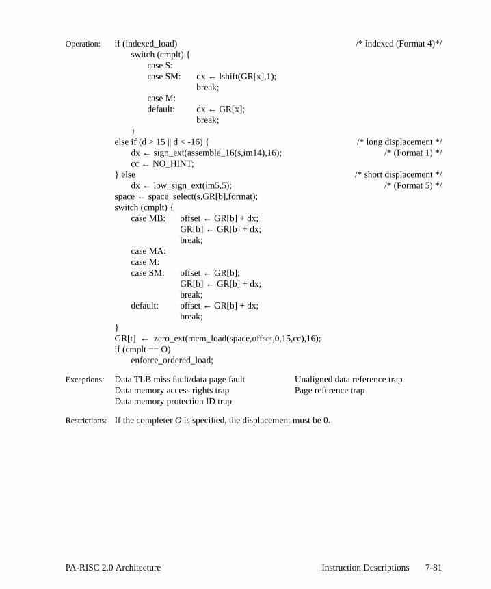
/*/
Operation: if (indexed_load) /* indexed (Format 4)*/switch (cmplt) {
case S:case SM: dx← lshift(GR[x],1);
break;case M:default: dx← GR[x];
break;}
else if (d > 15 || d < -16) { /* long displacement *dx ← sign_ext(assemble_16(s,im14),16); /* (Format 1) cc ← NO_HINT;
} else /* short displacement */dx ← low_sign_ext(im5,5); /* (Format 5) */
space← space_select(s,GR[b],format);switch (cmplt) {
case MB: offset← GR[b] + dx;GR[b] ← GR[b] + dx;break;
case MA:case M:case SM: offset← GR[b];
GR[b] ← GR[b] + dx;break;
default: offset← GR[b] + dx;break;
}GR[t] ← zero_ext(mem_load(space,offset,0,15,cc),16);if (cmplt == O)
enforce_ordered_load;
Exceptions: Data TLB miss fault/data page fault Unaligned data reference trapData memory access rights trap Page reference trapData memory protection ID trap
Restrictions: If the completerO is specified, the displacement must be 0.
7-81PA-RISC 2.0 Architecture Instruction Descriptions

ced
r
Load Immediate Left LDIL
Format: LDIL i,t
(7)
Purpose: To load the upper portion of a 32-bit immediate value into a general register.
Description: The 21-bit immediate value,i, is assembled, shifted left 11 bits, sign extended, and plain GR t.
Operation: GR[t] ← sign_ext(lshift(assemble_21(im21),11),32);
Exceptions: None
Notes: Memory is not referenced.
Programming NoteLOAD IMMEDIATE LEFT can be used to generate a 32-bit literal in an arbitrary general registet by the following sequence of assembly language code:
08 t im21
6 5 21
LDIL l%literal,GRt
LDO r%literal(GRt),GRt
7-82 Instruction Descriptions PA-RISC 2.0 Architecture
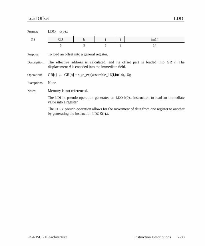
other
Load Offset LDO
Format: LDO d(b),t
(1)
Purpose: To load an offset into a general register.
Description: The effective address is calculated, and its offset part is loaded into GRt. Thedisplacementd is encoded into the immediate field.
Operation: GR[t] ← GR[b] + sign_ext(assemble_16(i,im14),16);
Exceptions: None
Notes: Memory is not referenced.
The LDI i,t pseudo-operation generates anLDO i(0),t instruction to load an immediatevalue into a register.
TheCOPY pseudo-operation allows for the movement of data from one register to anby generating the instructionLDO 0(r),t.
0D b t i im14
6 5 5 2 14
7-83PA-RISC 2.0 Architecture Instruction Descriptions

y the
ating
Load Space Identifier LDSID
Format: LDSID (s,b),t
(30)
Purpose: To calculate the space register number referenced by an implicit pointer and copspace register into a general register.
Description: If s is zero, the space identifier referenced by GRb is copied into GRt. If s is not zero, SRs is copied into GRt.
Operation: GR[t] ← space_select(s,GR[b],INDEXED);
Exceptions: None
Notes: Unimplemented space register bits must read as zero.
The target register receives an undefined value ifLDSID with a nonzeros-field is executedat a nonzero privilege level when the PSW W-bit is 1.
This instruction provides no useful function when the PSW W-bit is 1, since the opersystem is free to change the space register contents at any time.
00 b rv s 0 85 t
6 5 5 2 1 8 5
7-84 Instruction Descriptions PA-RISC 2.0 Architecture

1tional
baseegister1 onnics.)
13) isd. For
e
Load Word LDW
Format: LDW,cmplt,cc x|d(s,b),t
(1)
(2)
(5)
(4)
Purpose: To load a word into a general register.
Description: The aligned word, at the effective address, is zero-extended and loaded into GRt from theeffective address. The offset is formed as the sum of a base register,b, and either an indexregister,x (Format 4), or a displacementd. The displacement can be either long (Formatsand 2) or short (Format 5.) The displacement is encoded into the immediate field. Opbase modification can also be performed.
The completer,cmplt, determines whether the offset is the base register, or the register plus the index register or displacement. The completer also specifies base rmodification, optional index prescaling, and ordering constraints (see Table H-page H-4, and Table H-3 on page H-8 for the assembly language completer mnemoThe completer,cc, specifies the cache control hint (see Table 6-7 on page 6-10.)
For long displacements with pre-decrement or post-increment, Format 1 (opcode used. For long displacements with post-decrement or pre-increment, Format 2 is uselong displacements with no base modification, Format 1 (opcode 12) is used.
For short displacements, a one in them field specifies base modification, and thea fieldencodes whether pre-modification (a=1), or post-modification (a=0) is performed. Forindexed loads, a one in them field specifies base modification, and a one in theu fieldspecifies index prescaling.
If base register modification is specified andb = t, GR t receives the aligned word at theffective address.
12/13 b t s im14
6 5 5 2 14
17 b t s im11a 2 i
6 5 5 2 11 2 1
03 b im5 s a 1 cc 2 m t
6 5 5 2 1 1 2 4 1 5
03 b x s u 0 cc 2 m t
6 5 5 2 1 1 2 4 1 5
7-85PA-RISC 2.0 Architecture Instruction Descriptions

/
*/
*/
only
Operation: if (indexed_load) /* indexed (Format 4)*/switch (cmplt) {
case S:case SM: dx← lshift(GR[x],2);
break;case M:default: dx← GR[x];
break;}
else if (d > 15 || d < -16) { /* long displacement *if ((cmplt == MB && d >= 0) || (cmplt == MA && d < 0))
dx ← sign_ext(assemble_16a(s,im11a,i),16); /* (Format 2)else
dx ← sign_ext(assemble_16(s,im14),16); /* (Format 1) cc ← NO_HINT;
} else /* short displacement */dx ← low_sign_ext(im5,5); /* (Format 5) */
space← space_select(s,GR[b],format);switch (cmplt) {
case MB: offset← GR[b] + dx;GR[b] ← GR[b] + dx;break;
case MA:case M:case SM: offset← GR[b];
GR[b] ← GR[b] + dx;break;
default: offset← GR[b] + dx;break;
}GR[t] ← zero_ext(mem_load(space,offset,0,31,cc),32);if (cmplt == O)
enforce_ordered_load;
Exceptions: Data TLB miss fault/data page fault Unaligned data reference trapData memory access rights trap Page reference trapData memory protection ID trap
Restrictions: For post-decrement and pre-increment with long displacements (Format 2), displacements which are multiples of four may be used.
If the completerO is specified, the displacement must be 0.
7-86 Instruction Descriptions PA-RISC 2.0 Architecture

GR
eld.
baseegister1 onnics.)
e This
Load Word Absolute LDWA
Format: LDWA,cmplt,cc x|d(b),t
(5)
(4)
Purpose: To load a word into a general register from an absolute address.
Description: The aligned word at the effective absolute address is zero-extended and loaded intot.The offset is formed as the sum of a base register,b, and either an index register,x (Format4), or a displacementd (Format 5.) The displacement is encoded into the immediate fiOptional base modification can also be performed.
The completer,cmplt, determines whether the offset is the base register, or the register plus the index register or displacement. The completer also specifies base rmodification, optional index prescaling, and ordering constraints (see Table H-page H-4, and Table H-3 on page H-8 for the assembly language completer mnemoThe completer,cc, specifies the cache control hint (see Table 6-7 on page 6-10.)
For short displacements, a one in them field specifies base modification, and thea fieldencodes whether pre-modification (a=1), or post-modification (a=0) is performed. Forindexed loads, a one in them field specifies base modification, and a one in theu fieldspecifies index prescaling.
If base register modification is specified andb = t, GR t receives the aligned word at theffective address. Protection is not checked when this instruction is executed.operation is only defined if the address is aligned on a 4-byte boundary.
03 b im5 0 a 1 cc 6 m t
6 5 5 2 1 1 2 4 1 5
03 b x 0 u 0 cc 6 m t
6 5 5 2 1 1 2 4 1 5
7-87PA-RISC 2.0 Architecture Instruction Descriptions
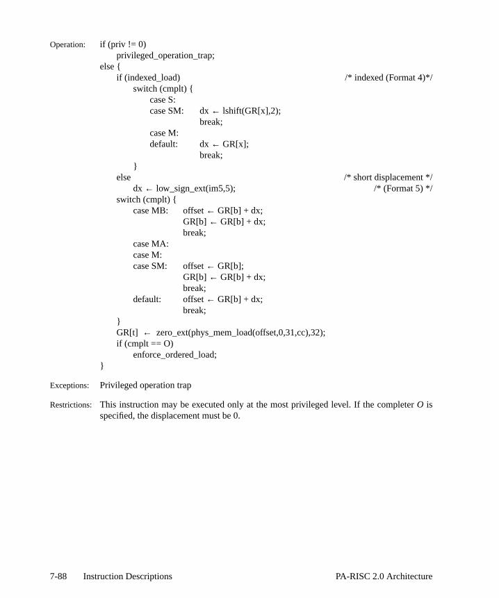
Operation: if (priv != 0)privileged_operation_trap;
else {if (indexed_load) /* indexed (Format 4)*/
switch (cmplt) {case S:case SM: dx← lshift(GR[x],2);
break;case M:default: dx← GR[x];
break;}
else /* short displacement */dx ← low_sign_ext(im5,5); /* (Format 5) */
switch (cmplt) {case MB: offset← GR[b] + dx;
GR[b] ← GR[b] + dx;break;
case MA:case M:case SM: offset← GR[b];
GR[b] ← GR[b] + dx;break;
default: offset← GR[b] + dx;break;
}GR[t] ← zero_ext(phys_mem_load(offset,0,31,cc),32);if (cmplt == O)
enforce_ordered_load;}
Exceptions: Privileged operation trap
Restrictions: This instruction may be executed only at the most privileged level. If the completerO isspecified, the displacement must be 0.
7-88 Instruction Descriptions PA-RISC 2.0 Architecture

3 on
ault isecifiedctive
d fromtate of
This
ult, theess. Iff notet the
Load Physical Address LPA
Format: LPA,cmplt x(s,b),t
(24)
Purpose: To determine the absolute address of a mapped virtual page.
Description: The effective address is calculated. The completer,cmplt, determines if the offset is thebase register,b, or the base register plus index registerx. The completer, encoded in themfield of the instruction, also specifies base register modification (see Table 7-page 7-52 for the assembly language completer mnemonics.) GRt receives the absoluteaddress corresponding to the given virtual address. If the page is not present, a ftaken and software sets the target register to 0. If base register modification is spandb = t, the value loaded is the absolute address of the item indicated by the effeaddress.
In systems with separate data and instruction TLBs, the absolute address is obtainethe data TLB. This instruction performs data address translation regardless of the sthe PSW D-bit.
Operation: if (priv != 0)privileged_operation_trap;
else {space← space_select(s,GR[b],INDEXED);switch (cmplt) {
case M: offset← GR[b]; /*m=1*/GR[b] ← GR[b] + GR[x];break;
default: offset← GR[b] + GR[x]; /*m=0*/break;
}if (DTLB_search(space,offset))
GR[t] ← absolute_address(space,offset);else
non-access_data_TLB_miss_fault();}
Exceptions: Non-access data TLB miss fault Privileged operation trap
Restrictions: The result ofLPA is ambiguous for an address which maps to absolute address 0.instruction may be executed only at the most privileged level.
Notes: If this instruction causes a non-access data TLB miss fault/non-access data page faoperating system’s handler is required to search its page tables for the given addrfound, it does the appropriate TLB insert and returns to the interrupting instruction. Ifound, the handler must decode the target field of the instruction, set that GR to 0, s
01 b x s 4D m t
6 5 5 2 8 1 5
7-89PA-RISC 2.0 Architecture Instruction Descriptions

IPSW[N] bit to 1, and return to the interrupting instruction.
7-90 Instruction Descriptions PA-RISC 2.0 Architecture
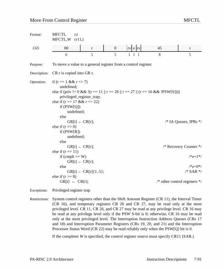
imer most may reads 17uption
Move From Control Register MFCTL
Format: MFCTL r,tMFCTL,W cr11,t
(32)
Purpose: To move a value to a general register from a control register.
Description: CR r is copied into GRt.
Operation: if (r >= 1 && r <= 7)undefined;
else if (priv != 0 && !(r == 11 || r == 26 || r == 27 || (r == 16 && !PSW[S])))privileged_register_trap;
else if (r >= 17 && r <= 22)if (PSW[Q])
undefined;else
GR[t] ← CR[r]; /* IA Queues, IPRs */else if (r == 0)
if (PSW[R])undefined;
elseGR[t] ← CR[r]; /* Recovery Counter */
else if (r == 11)if (cmplt == W) /*e=1*/
GR[t] ← CR[r];else /*e=0*/
GR[t] ← CR[r]{1..5}; /* SAR */else if (r >= 8)
GR[t] ← CR[r]; /* other control registers */
Exceptions: Privileged register trap
Restrictions: System control registers other than the Shift Amount Register (CR 11), the Interval T(CR 16), and temporary registers CR 26 and CR 27, may be read only at theprivileged level. CR 11, CR 26, and CR 27 may be read at any privilege level. CR 16be read at any privilege level only if the PSW S-bit is 0; otherwise, CR 16 may beonly at the most privileged level. The Interruption Instruction Address Queues (CRand 18) and Interruption Parameter Registers (CRs 19, 20, and 21) and the InterrProcessor Status Word (CR 22) may be read reliably only when the PSW[Q] bit is 0.
If the completerW is specified, the control register source must specify CR11 (SAR.)
00 r 0 rv e rv 45 t
6 5 5 1 1 1 8 5
7-91PA-RISC 2.0 Architecture Instruction Descriptions

Move From Instruction Address MFIA
Format: MFIA t
(32)
Purpose: To move the current instruction address to a general register.
Description: IAOQ_FRONT is copied into GRt. The rightmost two bits of GRt, corresponding to theprivilege level are zeroed.
Operation: GR[t] ← cat(IAOQ_FRONT{0..61},0{62..63});
Exceptions: None
00 rv 0 rv A5 t
6 5 5 3 8 5
7-92 Instruction Descriptions PA-RISC 2.0 Architecture
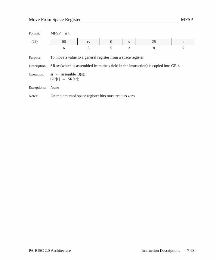
Move From Space Register MFSP
Format: MFSP sr,t
(29)
Purpose: To move a value to a general register from a space register.
Description: SRsr (which is assembled from thes field in the instruction) is copied into GRt.
Operation: sr ← assemble_3(s);GR[t] ← SR[sr];
Exceptions: None
Notes: Unimplemented space register bits must read as zero.
00 rv 0 s 25 t
6 5 5 3 8 5
7-93PA-RISC 2.0 Architecture Instruction Descriptions

ister.
dedleter
ult.ult.
Mix Halfwords MIXH
Format: MIXH,cmplt r1,r2,t
(10)
Purpose: To combine four halfwords from two source registers, and merge them in a result reg
Description: Two halfwords from GRr1 are merged with two halfwords from GRr2 and the result isplaced in GRt.
The completer,cmplt, determines which halfwords are selected. The completer is encoin the ea field of the instruction. (Table 7-6 defines the assembly language compmnemonics.)
If cmplt is “L”, the left halfword of each of the four input words is merged into the resIf cmplt is “R”, the right halfword of each of the four input words is merged into the resThe two cases are shown in the following diagram:
Operation: switch (cmplt) {case L: GR[t]← cat(GR[r1]{0..15},GR[r2]{0..15}, /*ea=0*/
GR[r1]{32..47},GR[r2]{32..47});break;
case R: GR[t]← cat(GR[r1]{16..31},GR[r2]{16..31}, /*ea=2*/GR[r1]{48..63}, GR[r2]{48..63});
break;}
Exceptions: None.
3E r2 r1 1 ea 0 1 0 0 t
6 5 5 1 2 1 2 4 1 5
Table 7-6. Mix Instruction Completers
cmplt Description ea
L Left Halfwords/Words are combined 0
R Right Halfwords/Words are combined 2
MIXH,L
r1
t
r2 ge f hda b c
a e c g
MIXH,R
r1
t
r2 ge f hda b c
b f d h
7-94 Instruction Descriptions PA-RISC 2.0 Architecture

r.
d inuagestram:
Mix Words MIXW
Format: MIXW,cmplt r1,r2,t
(10)
Purpose: To combine two words from two source registers, and merge them in a result registe
Description: A word from GRr1 is merged with a word from GRr2 and the result is placed in GRt.
The completer,cmplt, determines which words are selected. The completer is encodethe ea field of the instruction (see Table 7-6 on page 7-94 for the assembly langcompleter mnemonics.) Ifcmplt is “L”, the left word of each of the two input doublewordis merged into the result. Ifcmplt is “R”, the right word of each of the two inpudoublewords is merged into the result. The two cases are shown in the following diag
Operation: switch (cmplt) {case L: GR[t]← cat(GR[r1]{0..31},GR[r2]{0..31}); /*ea=0*/
break;case R: GR[t]← cat(GR[r1]{32..63},GR[r2]{32..63}); /*ea=2*/
break;}
Exceptions: None.
3E r2 r1 1 ea 0 0 0 0 t
6 5 5 1 2 1 2 4 1 5
MIXW,L
r1
t
r2
MIXW,R
r1
t
r2
a db c
ca
a b c d
b d
7-95PA-RISC 2.0 Architecture Instruction Descriptions

ed on
ethes
isch is.
-13 not thend set
Move and Branch MOVB
Format: MOVB,cond,n r1,r2,target
(17)
Purpose: To copy one register to another and perform an IA-relative branch conditionally basthe value moved.
Description: GR r1 is copied into GRr2. If the value moved satisfies the specified condition,cond, theword displacement is assembled from thew andw1 fields, sign extended, and added to thcurrent instruction offset plus 8 to form the target offset. The condition is encoded in cfield of the instruction. The branch target,target, in the assembly language format iencoded in thew andw1 fields.
If nullification is not specified, the following instruction is not nullified. If nullification specified, the instruction following a taken forward branch or a failing backward brannullified. The ,N completer, encoded in then field of the instruction, specifies nullification
Conditions: The condition,cond, is any of the extract/deposit 32-bit conditions shown in Table Don page D-9 (never, =, <, OD, TR, <>, >=, EV.) When a condition completer isspecified, the “never” condition is used. The boolean variable “cond_satisfied” inoperation section is set to 1 when the value moved satisfies the specified condition ato 0 otherwise.
Operation: GR[r2] ← GR[r1];disp ← lshift(sign_ext(assemble_12(w1,w),12),2);if (cond_satisfied)
IAOQ_Next ← IAOQ_Front + disp + 8;if (n)
if (disp < 0)PSW[N] ← !cond_satisfied;
elsePSW[N] ← cond_satisfied;
Exceptions: Taken branch trap
32 r2 r1 c w1 n w
6 5 5 3 11 1 1
7-96 Instruction Descriptions PA-RISC 2.0 Architecture

nch
thet,
isch is.
-13 not thend set
Move Immediate and Branch MOVIB
Format: MOVIB,cond,n i,r,target
(17)
Purpose: To copy an immediate value into a register and perform an IA-relative braconditionally based on the value moved.
Description: The immediate valueim5 is sign extended and copied into GRr. If the value movedsatisfies the specified condition,cond, the word displacement is assembled from thew andw1 fields, sign extended, and added to the current instruction offset plus 8 to formtarget offset. The condition is encoded in thec field of the instruction. The branch targetarget, in the assembly language format is encoded in thew andw1 fields.
If nullification is not specified, the following instruction is not nullified. If nullification specified, the instruction following a taken forward branch or a failing backward brannullified. The ,N completer, encoded in then field of the instruction, specifies nullification
Conditions: The condition,cond, is any of the extract/deposit 32-bit conditions shown in Table Don page D-9 (never, =, <, OD, TR, <>, >=, EV.) When a condition completer isspecified, the “never” condition is used. The boolean variable “cond_satisfied” inoperation section is set to 1 when the value moved satisfies the specified condition ato 0 otherwise.
Operation: GR[r] ← low_sign_ext(im5,5);disp ← lshift(sign_ext(assemble_12(w1,w),12),2);if (cond_satisfied)
IAOQ_Next ← IAOQ_Front + disp + 8;if (n)
if (disp < 0)PSW[N] ← !cond_satisfied;
elsePSW[N] ← cond_satisfied;
Exceptions: Taken branch trap
Programming NoteSince i is known at the time aMOVE IMMEDIATE AND BRANCH instruction is written,conditions other than always and never (the ,TR and <none> completers) are of no use.
33 r im5 c w1 n w
6 5 5 3 11 1 1
7-97PA-RISC 2.0 Architecture Instruction Descriptions

and
y a
Move To Control Register MTCTL
Format: MTCTL r,t
(31)
Purpose: To move a value from a general register to a control register.
Description: GR r is copied into CRt. If CR 23 is specified, then the value is first complemented ANDed with the original value.
Notes: The MTSAR r pseudo-operation generates an MTCTL r,%SAR instruction to copgeneral register to the Shift Amount Register.
00 t r rv C2 0
6 5 5 3 8 5
7-98 Instruction Descriptions PA-RISC 2.0 Architecture

rittenTheting intoessorpace
o
Operation: if (t >= 1 && t <= 7)undefined;
else if (t != 11 && priv != 0)privileged_register_trap;
elseswitch(t) {
case 0: if (PSW[R])undefined;
elseCR[t] ← GR[r]{32..63}; /* Recovery Counter */
break;case 14: case 15: case 16: case 24: case 25: case 26:case 27: case 28: case 29: case 30: case 31:
CR[t] ← GR[r]; /* other control registers */break;
case 17: case 18: case 20: case 21: case 22:if (PSW[Q])
undefined;else
CR[t] ← GR[r]; /* IIA Queues, IOR, ISR */break;
case 23: CR[23]← CR[23] & ∼GR[r]; /* EIRR */break;
case 10: CR[10]← GR[r]{48..63}; /* CCR, SCR */break;
case 11: CR[11]← GR[r]{26..31}; /* SAR */break;
case 8: case 9: case 12: case 13:CR[t] ← GR[r]; /* Protection Identifiers */break;
case 19:undefined; /* IIR */break;
}
Exceptions: Privileged register trap
Restrictions: System control registers other than the Shift Amount Register (CR 11) may be wonly at the most privileged level. CR 11 may be written at any privilege level. Recovery Counter (CR 0) may be written reliably only when the PSW[R] bit is 0. Wriinto the Interruption Instruction Register (CR 19) is an undefined operation. Writingthe Interruption Instruction Address Queues (CRs 17 and 18), the Interruption ProcStatus Word (CR 22), the Interruption Offset Register (CR 21) or the Interruption SRegister (CR 20) when the PSW[Q] bit is 1 is an undefined operation.
Notes: The MTSAR pseudo-operation generates anMTCTL r,CR11 to copy a general register tthe Shift Amount Register (CR 11.)
7-99PA-RISC 2.0 Architecture Instruction Descriptions

Shift
SARor they a
Move To Shift Amount Register Complement MTSARCM
Format: MTSARCM r
(31)
Purpose: To take the one’s complement of a value from a general register and move it to theAmount Register (CR11.)
Description: The one’s complement of GRr is copied into CR[11].
Operation: CR[11] ← ~ GR[r]{26..31};
Exceptions: None.
Notes: The upper bits of the SAR are non-existent and so on a MFCTL instruction with the as the specified register, hardware can return either 0’s or what was last written fupper 58 bits. If hardware returns what was last written, the value written bMTSARCM instruction must be the complement of GR[r].
00 B r rv C6 0
6 5 5 3 8 5
7-100 Instruction Descriptions PA-RISC 2.0 Architecture

thened
used
Move To System Mask MTSM
Format: MTSM r
(33)
Purpose: To set PSW system mask bits to a value from a register.
Description: Bits 36, 37 and 56..63 of GRr replace the system mask, PSW{36,37,56..63}. Setting PSW Q-bit, PSW{60}, to 1 with this instruction, if it was not already 1, is an undefioperation.
Operation: if (priv != 0)privileged_operation_trap;
else {if ((PSW[Q] == 0) && (GR[r]{60} == 1))
undefined;else {
PSW[W]← GR[r]{36};PSW[E]← GR[r]{37};PSW[O]← GR[r]{56};PSW[G]← GR[r]{57};PSW[F] ← GR[r]{58};PSW[R]← GR[r]{59};PSW[Q]← GR[r]{60};PSW[P]← GR[r]{61};PSW[D]← GR[r]{62};PSW[I] ← GR[r]{63};
}}
Exceptions: Privileged operation trap
Restrictions: This instruction may be executed only at the most privileged level.
Notes: The state of the IPRs, IIA queues, and the IPSW is undefined when this instruction isto set the Q-bit to 0, if it was not already 0.
00 0 r 0 C3 0
6 5 5 3 8 5
7-101PA-RISC 2.0 Architecture Instruction Descriptions

l.
tion if
Move To Space Register MTSP
Format: MTSP r,sr
(29)
Purpose: To move a value from a general register to a space register.
Description: GR r is copied into SRsr (which is assembled from thes field in the instruction.)
Operation: sr ← assemble_3(s);if (sr >= 5 && priv != 0)
privileged_register_trap;else
if (PSW[W])SR[sr] ← GR[r];
elseSR[sr]{32..63}← GR[r]{32..63};
Exceptions: Privileged register trap
Restrictions: SRs 5, 6 and 7 may be changed only by software running at the most privileged leve
Notes: The values written to unimplemented space register bits must be ignored.
Bits 0..31 of the target space register, if implemented, are unchanged by this instructhe PSW W-bit is 0.
00 rv r s C1 0
6 5 5 3 8 5
7-102 Instruction Descriptions PA-RISC 2.0 Architecture

7 oritioniableecified
Inclusive OR OR
Format: OR,cond r1,r2,t
(8)
Purpose: To do a 64-bit, bitwise inclusive OR.
Description: GR r1 and GRr2 are ORed and the result is placed in GRt. The following instruction isnullified if the values ORed satisfy the specified condition,cond. The condition is encodedin thec, d, andf fields of the instruction.
Conditions: The condition is any of the 32-bit logical conditions shown in Table D-9 on page D-any of the 64-bit logical conditions shown in Table D-10 on page D-7. When a condcompleter is not specified, the "never" condition is used. The boolean var"cond_satisfied" in the operation section is set when the values ORed satisfy the spcondition.
Operation: GR[t] ← GR[r1] | GR[r2];if (cond_satisfied) PSW[N]← 1;
Exceptions: None
Notes: TheNOP pseudo-operation generates the instructionOR 0,0,0.
02 r2 r1 c f 0 1 0 1 d t
6 5 5 3 1 2 1 1 2 1 5
7-103PA-RISC 2.0 Architecture Instruction Descriptions
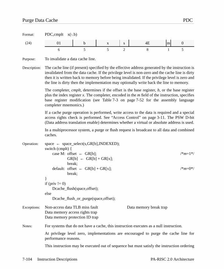
tion is dirty and.
guage
special D-bitis used.
bined
e for
ering
Purge Data Cache PDC
Format: PDC,cmplt x(s,b)
(24)
Purpose: To invalidate a data cache line.
Description: The cache line (if present) specified by the effective address generated by the instrucinvalidated from the data cache. If the privilege level is non-zero and the cache line isthen it is written back to memory before being invalidated. If the privilege level is zerothe line is dirty then the implementation may optionally write back the line to memory
The completer,cmplt, determines if the offset is the base register,b, or the base registerplus the index registerx. The completer, encoded in them field of the instruction, specifiesbase register modification (see Table 7-3 on page 7-52 for the assembly lancompleter mnemonics.)
If a cache purge operation is performed, write access to the data is required and a access rights check is performed. See “Access Control” on page 3-11. The PSW(Data address translation enable) determines whether a virtual or absolute address
In a multiprocessor system, a purge or flush request is broadcast to all data and comcaches.
Operation: space← space_select(s,GR[b],INDEXED);switch (cmplt) {
case M: offset← GR[b]; /*m=1*/GR[b] ← GR[b] + GR[x];break;
default: offset← GR[b] + GR[x]; /*m=0*/break;
}if (priv != 0)
Dcache_flush(space,offset);else
Dcache_flush_or_purge(space,offset);
Exceptions: Non-access data TLB miss fault Data memory break trapData memory access rights trapData memory protection ID trap
Notes: For systems that do not have a cache, this instruction executes as a null instruction.
At privilege level zero, implementations are encouraged to purge the cache linperformance reasons.
This instruction may be executed out of sequence but must satisfy the instruction ord
01 b x s 4E m 0
6 5 5 2 8 1 5
7-104 Instruction Descriptions PA-RISC 2.0 Architecture

ons
constraints. TheSYNC instruction enforces program order with respect to the instructifollowing theSYNC.It is an undefined operation to execute aPDC with a nonzeros-field at a nonzero privilegelevel when the PSW W-bit is 1.
7-105PA-RISC 2.0 Architecture Instruction Descriptions

y
or
e
s must
a
Purge Data TLB PDTLB
Format: PDTLB,scope,cmplt x(s,b)
(24)
Purpose: To invalidate a data TLB entry.
Description: The data or combined TLB entries (if any) which match the effective address generated bthe instruction are removed. The completer, scope, encoded in the e1 field of theinstruction, specifies whether the purge is global to all processors in a multiprocesssystem (no completer, e1=0) or limited to the local processor (,L completer, e1=1.) Thecompleter, cmplt, encoded in the m field of the instruction, determines if the offset is thebase register, b, or the base register plus index register, x, and whether base registermodification is performed (see Table7-3 on page7-52 for the assembly languagcompleter mnemonics.)
TLB purges are strongly ordered. In a multiprocessor system, a global TLB purge causes apurge request to be broadcast to all data and combined TLBs. The other processorremove all matching entries before the issuing processor continues.
Operation: if (priv != 0)privileged_operation_trap;
else {space ← space_select(s,GR[b],INDEXED);switch (cmplt) {
case M: offset ← GR[b]; /*m=1*/GR[b] ← GR[b] + GR[x];break;
default: offset ← GR[b] + GR[x]; /*m=0*/break;
}page_size ← 4096 << (2 * GR[b]{60..63});for (i ← 0; i < page_size/4096; i++) {
if (entry ← DTLB_search(space, offset + i*4096))DTLB_purge_local(entry);
}if (scope != L)
DTLB_purge_broadcast(space,offset,page_size);}
Exceptions: Privileged operation trap.
Restrictions: This instruction may be executed only at the most privileged level.
Notes: This instruction may be used to purge both instruction entries and data entries fromcombined TLB.
01 b x s 2 e1 8 m rv
6 5 5 2 3 1 4 1 5
7-106 Instruction Descriptions PA-RISC 2.0 Architecture

dentlds ofvalidatee
52 for
e data a
om aace”
Purge Data TLB Entry PDTLBE
Format: PDTLBE,cmplt x(s,b)
(24)
Purpose: To invalidate a data TLB entry without matching the address portion.
Description: The data or combined TLB entries (if any) specified by an implementation-depenfunction of the effective address generated by the instruction are removed. All the fiethese entries may be changed to arbitrary values as long as these entries do not any subsequent accesses. The completer,cmplt, determines if the offset is the basregister,b, or the base register plus the index registerx. The completer, encoded in themfield of the instruction, specifies base register modification (see Table 7-3 on page 7-the assembly language completer mnemonics.)
This is an implementation-dependent instruction that can be used to purge the entirTLB without knowing the translations in the TLB. No broadcast occurs inmultiprocessor system.
Operation: if (priv != 0)privileged_operation_trap;
else {space← space_select(s,GR[b],INDEXED);switch (cmplt) {
case M: offset← GR[b]; /*m=1*/GR[b] ← GR[b] + GR[x];break;
default: offset← GR[b] + GR[x]; /*m=0*/break;
}DTLB_purge_entries(space,offset);
}
Exceptions: Privileged operation trap
Restrictions: This instruction may be executed only at the most privileged level.
Notes: This instruction may be used to purge both instruction entries and data entries frcombined TLB. This instruction does not necessarily purge the entry specified by “spand “offset”.
01 b x s 49 m rv
6 5 5 2 8 1 5
7-107PA-RISC 2.0 Architecture Instruction Descriptions

that
ed, one
ter digitat theelects
-
ter
the
Permute Halfwords PERMH
Format: PERMH,c r,t
(10)
Purpose: To select any combination of four halfwords from a source register, and placecombination in a result register.
Description: The source register, GRr, is treated as four 16-bit fields. A 64-bit result is generatconsisting of four 16-bit fields. Each field in the result is independently selected fromof the fields in GRr. The result is placed in GRt.
The choice of which fields are selected for each result field is specified by the complec,which is given as a four-digit number, where each digit is either 0, 1, 2, or 3. Eachcontrols the selection for one result field. For example, a digit value of 0 specifies thresult field receives the value from the leftmost source field, and a digit value of 2 sthe next-to-rightmost source field.c is encoded in thec0, c1, c2, andc3 fields of theinstruction.c0 encodes the first digit,c1 the second, etc. Thus,c0 encodes which sourcefield will appear in the leftmost result field,c1 which source field will appear in the nextto-leftmost result field, etc.
The array of boolean variables “c[]” in the operation section represent the complec.The variable “c[0]” represents the first digit inc, “c[1]” the second digit inc, etc.
Any combination or permutation of the four source fields can be generated.
Operation: parallel for (i← 0; i <= 3; i++) {start← 16 * i;end← start + 15;field_select← c[i];switch (field_select) {
case 0: GR[t]{start..end}← GR[r]{0..15};break;
case 1: GR[t]{start..end}← GR[r]{16..31};break;
case 2: GR[t]{start..end}← GR[r]{32..47};break;
case 3: GR[t]{start..end}← GR[r]{48..63};break;
}}
Exceptions: None.
Notes: The source register specifier,r, must appear in both source operand fields of instruction, as shown in the format. If it does not, the operation is undefined.
3E r r 0 c0 0 c1 c2 c3 0 t
6 5 5 1 2 1 2 2 2 1 5
7-108 Instruction Descriptions PA-RISC 2.0 Architecture

e
Programming NoteThe following figures illustrate examples of how the source fields are specified and how thresult is generated.
c= 0000
a dr
a at a a
c= 2031
a dr
c bt a d
b c
b c
c= 3210
a dr
d at c b
b c
0 1 2 3
0 1 2 3
0 1 2 3
7-109PA-RISC 2.0 Architecture Instruction Descriptions

essors
a
Purge Instruction TLB PITLB
Format: PITLB,scope,cmplt x(sr,b)
(26)
Purpose: To invalidate an instruction TLB entry.
Description: The instruction or combined TLB entry (if any) for the page specified by the effectiveaddress generated by the instruction is removed. The completer, scope, encoded in the e1field of the instruction, specifies whether the purge is global to all processors in amultiprocessor system (no completer, e1=0) or limited to the local processor (,Lcompleter, e1=1.) The completer, cmplt, encoded in the m field of the instruction,determines if the offset is the base register, b, or the base register plus index register, x, andwhether base register modification is performed (see Table7-3 on page7-52 for theassembly language completer mnemonics.)
TLB purges are strongly ordered. In a multiprocessor system, a global TLB purge causes apurge request to be broadcast to all instruction and combined TLBs. The other procmust remove the entry before the issuing processor continues.
Operation: if (priv != 0)privileged_operation_trap;
else {space ← SR[assemble_3(s)];switch (cmplt) {
case M: offset ← GR[b]; /*m=1*/GR[b] ← GR[b] + GR[x];break;
default: offset ← GR[b] + GR[x]; /*m=0*/break;
}page_size ← 4096 << (2 * GR[b]{60..63});for (i ← 0; i < page_size/4096; i++) {
if (entry ← ITLB_search(space, offset + i*4096))ITLB_purge_local(entry);
}if (scope != L)
ITLB_purge_broadcast(space,offset,page_size);}
Exceptions: Privileged operation trap
Restrictions: This instruction may be executed only at the most privileged level.
Notes: This instruction may be used to purge both instruction entries and data entries fromcombined TLB.
01 b x s 0 e1 8 m rv
6 5 5 3 2 1 4 1 5
7-110 Instruction Descriptions PA-RISC 2.0 Architecture
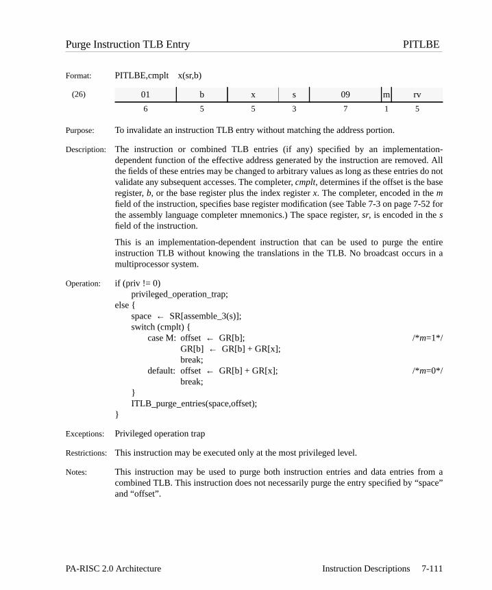
ion-d. All
s do note
52 for
entirein a
om aace”
Purge Instruction TLB Entry PITLBE
Format: PITLBE,cmplt x(sr,b)
(26)
Purpose: To invalidate an instruction TLB entry without matching the address portion.
Description: The instruction or combined TLB entries (if any) specified by an implementatdependent function of the effective address generated by the instruction are removethe fields of these entries may be changed to arbitrary values as long as these entrievalidate any subsequent accesses. The completer,cmplt, determines if the offset is the basregister,b, or the base register plus the index registerx. The completer, encoded in themfield of the instruction, specifies base register modification (see Table 7-3 on page 7-the assembly language completer mnemonics.) The space register,sr, is encoded in thesfield of the instruction.
This is an implementation-dependent instruction that can be used to purge the instruction TLB without knowing the translations in the TLB. No broadcast occurs multiprocessor system.
Operation: if (priv != 0)privileged_operation_trap;
else {space← SR[assemble_3(s)];switch (cmplt) {
case M: offset← GR[b]; /*m=1*/GR[b] ← GR[b] + GR[x];break;
default: offset← GR[b] + GR[x]; /*m=0*/break;
}ITLB_purge_entries(space,offset);
}
Exceptions: Privileged operation trap
Restrictions: This instruction may be executed only at the most privileged level.
Notes: This instruction may be used to purge both instruction entries and data entries frcombined TLB. This instruction does not necessarily purge the entry specified by “spand “offset”.
01 b x s 09 m rv
6 5 5 3 7 1 5
7-111PA-RISC 2.0 Architecture Instruction Descriptions

get
Pop Branch Target Stack POPBTS
Format: POPBTS i
(23)
Purpose: To pop one or more entries off the branch target stack.
Description: The top i entries of the branch target stack are popped.
If this instruction is nullified, the results are undefined.
This instruction is executed as aNOP on machines that do not implement the branch tarstack.
Operation: for (j=i; j>0; j--) {pop_from_BTS();
}
Exceptions: None
3A 0 0 2 0 i 1 0 1
6 5 5 3 1 9 1 1 1
7-112 Instruction Descriptions PA-RISC 2.0 Architecture

tion is
also of the
*/
*/
ult, theess. Iff notet the
Probe Access PROBE
Format: PROBE,cmplt (s,b),r,t
(24)
Purpose: To determine whether read or write access to a given address is allowed.
Description: A test is performed to determine if access to the address computed by the instrucpermitted at the privilege level given by the two rightmost bits of the GRr. GRt is set to 1if the test succeeds and 0 otherwise.
The completer,cmplt, encoded in the sub-operation fielde1, specifies whether theinstruction checks for read (cmplt ==R) or write (cmplt ==W) access (e1=0: check for readaccess,e1=1: check for write access.) If the PSW P-bit is 1, the protection IDs are checked. The instruction performs data address translation regardless of the statePSW D-bit.
Operation: space← space_select(s,GR[b],INDEXED);offset ← GR[b];if (DTLB_search(space,offset))
switch (cmplt) {case W: if (write_access_allowed(space,offset,GR[r])) /*e1=1
GR[t] ← 1;else
GR[t] ← 0;break;
case R:default: if (read_access_allowed(space,offset,GR[r])) /*e1=0
GR[t] ← 1;else
GR[t] ← 0;break;
}else
non-access_data_TLB_miss_fault();
Exceptions: Non-access data TLB miss fault/non-access data page fault
Notes: If this instruction causes a non-access data TLB miss fault/non-access data page faoperating system’s handler is required to search its page tables for the given addrfound, it does the appropriate TLB insert and returns to the interrupting instruction. Ifound, the handler must decode the target field of the instruction, set that GR to 0, sIPSW[N] bit to 1, and return to the interrupting instruction.
It is an undefined operation to execute aPROBE with a nonzeros-field at a nonzeroprivilege level when the PSW W-bit is 1.
01 b r s 23 e1 0 t
6 5 5 2 7 1 1 5
7-113PA-RISC 2.0 Architecture Instruction Descriptions

I
tion isue
also of the
*/
*/
ult, theess. Iff notet the
Probe Access Immediate PROBE
Format: PROBEI,cmplt (s,b),i,t
(24)
Purpose: To determine whether read or write access to a given address is allowed.
Description: A test is performed to determine if access to the address computed by the instrucpermitted at the privilege level given by the two rightmost bits of the immediate vali.GR t is set to 1 if the test succeeds and 0 otherwise.
The completer,cmplt, encoded in the sub-operation fielde1, specifies whether theinstruction checks for read (cmplt ==R) or write (cmplt ==W) access (e1=0: check for readaccess,e1=1: check for write access.) If the PSW P-bit is 1, the protection IDs are checked. This instruction performs data address translation regardless of the statePSW D-bit.
Operation: space← space_select(s,GR[b],INDEXED);offset ← GR[b];if (DTLB_search(space,offset))
switch (cmplt) {case W: if (write_access_allowed(space,offset,i)) /*e1=1
GR[t] ← 1;else
GR[t] ← 0;break;
case R:default: if (read_access_allowed(space,offset,i)) /*e1=0
GR[t] ← 1;else
GR[t] ← 0;break;
}else
non-access_data_TLB_miss_fault();
Exceptions: Non-access data TLB miss fault/non-access data page fault
Notes: If this instruction causes a non-access data TLB miss fault/non-access data page faoperating system’s handler is required to search its page tables for the given addrfound, it does the appropriate TLB insert and returns to the interrupting instruction. Ifound, the handler must decode the target field of the instruction, set that GR to 0, sIPSW[N] bit to 1, and return to the interrupting instruction.
It is an undefined operation to execute aPROBEI with a nonzeros-field at a nonzeroprivilege level when the PSW W-bit is 1.
01 b i s 63 e1 0 t
6 5 5 2 7 1 1 5
7-114 Instruction Descriptions PA-RISC 2.0 Architecture

get
Push Branch Target Stack PUSHBTS
Format: PUSHBTS r
(23)
Purpose: To push a value from a GR onto the branch target stack.
Description: Either the value in GRr, or an “invalid” value is pushed onto the branch target stack.
If this instruction is nullified, the results are undefined.
This instruction is executed as aNOP on machines that do not implement the branch tarstack.
Operation: push_onto_BTS(GR[b]{0..61});
Exceptions: None.
3A 0 r 2 0 0 0 0 1
6 5 5 3 1 9 1 1 1
7-115PA-RISC 2.0 Architecture Instruction Descriptions

rwise,
get
Push Nominated PUSHNOM
Format: PUSHNOM
(23)
Purpose: To push the currently nominated address onto the branch target stack.
Description: If there is a current nominated value, it is pushed onto the branch target stack. Othean “invalid” value is pushed.
If this instruction is nullified, the results are undefined.
This instruction is executed as aNOP on machines that do not implement the branch tarstack.
Operation: push_onto_BTS(BNR);
Exceptions: None.
3A 0 0 2 0 0 0 0 1
6 5 5 3 1 9 1 1 1
7-116 Instruction Descriptions PA-RISC 2.0 Architecture

m and
ed byes at
s
tents of
thele for
of anilege
Return From Interruption RFI
Format: RFI,cmplt
(33)
Purpose: To restore processor state and restart execution of an interrupted instruction streaoptionally restore GRs 1, 8, 9, 16, 17, 24, and 25 from the shadow registers.
Description: The PSW register contents are restored from the IPSW register but are not modifithis instruction. The IA queues are restored from the IIA queues. Execution continuthe locations loaded into the IA queues.
The completer,cmplt, encoded in the sub-operation fielde1, specifies whether the contentof GRs 1, 8, 9, 16, 17, 24, and 25 are restored from the shadow registers (e1=5: restorefrom shadow registers,e1=0: GRs are unchanged.) Execution of anRFI with the ,Rcompleter when the contents of the shadow registers are undefined leaves the conGRs 1, 8, 9, 16, 17, 24, and 25 undefined. After execution of anRFI with the ,R completer,the SHRs are undefined.
Execution of anRFI with the IPSW Q-bit equal to 0 returns to the location specified byIIA queues, but leaves the IIAOQ, IIASQ, and IPRs undefined. Software is responsibavoiding interruptions during the execution of anRFI. Execution of anRFI instructionwhen any of the PSW Q, I, or R bits are ones is an undefined operation. ExecutionRFI instruction when the PSW L-bit is a one is an undefined operation if the new privlevel after execution of theRFI is non zero.
00 rv rv rv 6 e1 0
6 5 5 3 4 4 5
7-117PA-RISC 2.0 Architecture Instruction Descriptions

le forof anyW B-tion ofavoid
with
el, a
Operation: if (priv != 0)privileged_operation_trap;
else {if (cmplt == R) {
GR[1] ← SHR[0]; /*e1=5*/GR[8] ← SHR[1];GR[9] ← SHR[2];GR[16] ← SHR[3];GR[17] ← SHR[4];GR[24] ← SHR[5];GR[25] ← SHR[6];
} else; /* do nothing */ /*e1=0*/
PSW ← IPSW;IAOQ_Back ← IIAOQ_Back;IAOQ_Front ← IIAOQ_Front;if (!level_0) {
IASQ_Back ← IIASQ_Back & ~zero_ext(IIAOQ_Back{0..31},32);IASQ_Front← IIASQ_Front & ~zero_ext(IIAOQ_Front{0..31},32);
}}
Exceptions: Privileged operation trap
Restrictions: This instruction may be executed only at the most privileged level.
Because this instruction restores the state of the execution pipeline, it is possibsoftware to place the processor in states which could not result from the execution sequence of instructions not involving interruptions. For example, it could set the PSbit to 0 even though the addresses in the IA queues are not contiguous. The operathe machine is undefined in such cases, and it is the responsibility of software to them.
To avoid improper processor states, software must not set the PSW B-bit to 0different privilege levels in the IAOQ.
Notes: When this instruction returns to an instruction which executes at a lower privilege levlower-privilege transfer trap is not taken.
This instruction is the only instruction that can set the PSW Q-bit to 1.
7-118 Instruction Descriptions PA-RISC 2.0 Architecture

used
Reset System Mask RSM
Format: RSM i,t
(33)
Purpose: To selectively reset bits in the system mask to 0.
Description: The current value of the system mask, PSW{36,37,56..63}, is saved in GRt and then thecomplement of the immediate valuei is ANDed with the system mask.
Operation: if (priv != 0)privileged_operation_trap;
else {GR[t] ← 0;GR[t]{36} ← PSW[W];GR[t]{37} ← PSW[E];GR[t]{56} ← PSW[O];GR[t]{57} ← PSW[G];GR[t]{58} ← PSW[F];GR[t]{59} ← PSW[R];GR[t]{60} ← PSW[Q];GR[t]{61} ← PSW[P];GR[t]{62} ← PSW[D];GR[t]{63} ← PSW[I];PSW[W]← PSW[W] & (~i{0});PSW[E]← PSW[E] & (~i{1});PSW[O]← PSW[O] & (~i{2});PSW[G]← PSW[G] & (~i{3});PSW[F] ← PSW[F] & (~i{4});PSW[R]← PSW[R] & (~i{5});PSW[Q]← PSW[Q] & (~i{6});PSW[P]← PSW[P] & (~i{7});PSW[D]← PSW[D] & (~i{8});PSW[I] ← PSW[I] & (~i{9});
}
Exceptions: Privileged operation trap
Restrictions: This instruction may be executed only at the most privileged level.
Notes: The state of the IPRs, IIA queues, and the IPSW is undefined when this instruction isto set the Q-bit to 0, if it was not already 0.
00 i 0 73 t
6 10 3 8 5
7-119PA-RISC 2.0 Architecture Instruction Descriptions

-bit
takenand is
ion,
gned
/
outredut are, it isecial
ther a
r anyleterin the
Shift Left and Add SHLADD
Format: SHLADD,cmplt,cond r1,sa,r2,t
(8)
Purpose: To provide a primitive operation for multiplication.
Description: GR r1 is shifted leftsa bit positions and added to GRr2. If no trap occurs, the result isplaced in GRt. The variable "carry_borrows" in the operation section captures the 4carries resulting from the add operation. The completer,cmplt, encoded in thee1 field,specifies whether the carry/borrow bits in the PSW are updated and whether a trap ison signed overflow as shown in the table below. The shift amount is either 1, 2, or 3, encoded in thesa field of the instruction.
The following instruction is nullified if the values added satisfy the specified conditcond. The condition is encoded in thec, d, and f fields of the instruction. The booleanvariable "overflow" in the operation section is set if the operation results in a 32-bit sioverflow (d=0) or a 64-bit signed overflow (d=1.) For addition with carry in, thed fieldencodes whether the word carry (PSW C/B{8},d=0), or the doubleword carry (PSW CB{0}, d=1) is used.
For this instruction, signed overflow condition means that either the bit(s) shifteddiffer from the leftmost bit following the shift or an ordinary signed overflow occurduring the addition. Unsigned overflow means that one or more of the bit(s) shifted o1 or an ordinary unsigned overflow occurred during the addition. For 32-bit overflowsthe bits shifted out of the lower word that are checked. The conditions take on spinterpretations since the shift operation participates in overflow determination.
Thee1 field encodes whether the carry/borrow bits in the PSW are updated and whetrap is taken on overflow (e1=1: carries updated, no trap,e1=2: carries not updated, notrap,e1=3: carries updated, trap on overflow.)
Conditions: The condition is any of the 32-bit add conditions shown in Table D-6 on page D-5 oof the 64-bit add conditions shown in Table D-7 on page D-6. When a condition compis not specified, the "never" condition is used. The boolean variable "cond_satisfied" operation section is set when the values added satisfy the specified condition.
02 r2 r1 c f e1 1 0 sa d t
6 5 5 3 1 2 1 1 2 1 5
Completer Description e1
<none> Shift left and add 1L Shift left and add logical 2TSV Shift left and add and trap on signed overflow 3
7-120 Instruction Descriptions PA-RISC 2.0 Architecture

Operation: res← lshift(GR[r1],sa) + GR[r2];if (cmplt == TSV && overflow)
overflow_trap;else {
GR[t] ← res;if (cmplt != ’L’)
PSW[C/B] ← carry_borrows;if (cond_satisfied) PSW[N]← 1;
}
Exceptions: Overflow trap
Notes: When the ,L completer is specified, no trapping on overflow is available.
7-121PA-RISC 2.0 Architecture Instruction Descriptions

the
t
, theiable
ified
on. Theof the
Shift Right Pair Doubleword SHRPD
Format: SHRPD,cond r1,r2,sa,t
(11)
(14)
Purpose: To shift a pair of registers by a fixed or variable amount and conditionally nullify following instruction.
Description: The rightmost 63 bits of GRr1 are concatenated with the 64 bits of GRr2 and shiftedright the number of bits given by the shift amount,sa. The rightmost 64 bits of the resulare placed in GRt.
The shift amount,sa, can either be a constant (specifying a fixed shift), or can be SARShift Amount Register (CR 11) (specifying a variable shift.) Format 11 is used for varshifts; Format 14 is used for fixed shifts. For fixed shifts, the shift amountsa in theassembly language format is represented by cat(cp,cpos) in the machine instruction,whose value is 63–sa.
The following instruction is nullified if the result of the operation satisfies the speccondition,cond. The condition is encoded in thec field of the instruction.
Conditions: The condition is any of the 64-bit extract/deposit conditions shown in Table D-14page D-9. When a condition completer is not specified, the "never" condition is usedboolean variable "cond_satisfied" in the operation section is set when the result operation satisfies the specified condition.
Operation: if (fixed_shift) /* (Format 14) */shamt← sa;
else /* (Format 11) */shamt← CR[11];
GR[t] ← rshift(cat(GR[r1]{1..63},GR[r2]),shamt){63..126};if (cond_satisfied) PSW[N]← 1;
Exceptions: None.
34 r2 r1 c 0 0 1 0 t
6 5 5 3 2 1 1 4 5
34 r2 r1 c 0 cp 1 cpos t
6 5 5 3 1 1 1 5 5
7-122 Instruction Descriptions PA-RISC 2.0 Architecture

Programming NoteA logical right shift of GRr by a variable amount contained in GRp leaving the result in GRtmay be done by the following sequence:
An arithmetic right shift can be done with an extract instruction. SeeEXTRACTDOUBLEWORD for an example.
If r1 andr2 name the same register, its contents are rotated and placed in GRt. For example,the following rotates the contents ofra right by 8 bits:
MTSAR pSHRPD 0,r,sar,t
SHRPD ra,ra,8,ra
7-123PA-RISC 2.0 Architecture Instruction Descriptions

and
, theiableR is
ified
on. Theof the
Shift Right Pair Word SHRPW
Format: SHRPW,cond r1,r2,sa,t
(11)
(14)
Purpose: To shift the rightmost 32 bits of a pair of registers by a fixed or variable amountconditionally nullify the following instruction.
Description: The rightmost 31 bits of GRr1 are concatenated with the rightmost 32 bits of GRr2 andshifted right the number of bits given by the shift amount,sa. The rightmost 32 bits of theresult are placed in GRt. The leftmost 32 bits of GRt are undefined.
The shift amount,sa, can either be a constant (specifying a fixed shift), or can be SARShift Amount Register (CR 11) (specifying a variable shift.) Format 11 is used for varshifts; Format 14 is used for fixed shifts. For variable shifts, the leftmost bit of the SAignored, so the shift amount is between 0 and 31. For fixed shifts, the shift amountsa inthe assembly language format is represented bycpos in the machine instruction, whosevalue is 31–sa.
The following instruction is nullified if the result of the operation satisfies the speccondition,cond. The condition is encoded in thec field of the instruction.
Conditions: The condition is any of the 32-bit extract/deposit conditions shown in Table D-13page D-9. When a condition completer is not specified, the "never" condition is usedboolean variable "cond_satisfied" in the operation section is set when the result operation satisfies the specified condition.
Operation: if (fixed_shift) /* (Format 14) */shamt← sa;
else /* (Format 11) */shamt← CR[11]{1..5};
GR[t]{32..63} ← rshift(cat(GR[r1]{33..63},GR[r2]{32..63}),shamt){31..62};GR[t]{0..31} ← undefined;if (cond_satisfied) PSW[N]← 1;
Exceptions: None.
34 r2 r1 c 0 0 0 0 t
6 5 5 3 2 1 1 4 5
34 r2 r1 c 0 1 0 cpos t
6 5 5 3 1 1 1 5 5
7-124 Instruction Descriptions PA-RISC 2.0 Architecture

Programming NoteA logical right shift of GRr by a variable amount contained in GRp leaving the result in GRtmay be done by the following sequence:
An arithmetic right shift can be done with an extract instruction. SeeEXTRACT WORD for anexample.
If r1 andr2 name the same register, its contents are rotated and placed in GRt. For example,the following rotates the contents ofra right by 8 bits:
MTSAR pSHRPW 0,r,sar,t
SHRPW ra,ra,8,ra
7-125PA-RISC 2.0 Architecture Instruction Descriptions

ionthat
Special Operation Zero SPOP0
Format: SPOP0,sfu,sop,n
(34)
Purpose: To invoke a special function unit operation.
Description: The SFU identified bysfu is directed to perform the operation specified by the informatsupplied to it. If nullification is specified, the SFU also computes a 1-bit condition causes the following instruction to be nullified if the condition is satisfied.
Thesop field in the assembly language format is the concatenation of thesop1 andsop2fields in the machine instruction, sop = cat(sop1,sop2.)
Operation: sfu_operation0(cat(sop1,sfu,n,sop2),IAOQ_Front{30..31});if (n && sfu_condition0(cat(sop1,sfu,n,sop2),IAOQ_Front{30..31}))
PSW[N] ← 1;
Exceptions: Assist emulation trap Assist exception trap
04 sop1 0 sfu n sop2
6 15 2 3 1 5
7-126 Instruction Descriptions PA-RISC 2.0 Architecture

lationction
ecialndU is
ion ofhandlerd and
Special Operation One SPOP1
Format: SPOP1,sfu,sop,n t
(35)
Purpose: To copy a special function unit register or a result to a general register.
Description: A single word is sent from the SFU identified bysfu to GR t. The SFU uses its internastate and the instruction fields supplied to it to compute or select the result. If nullificis specified, the SFU also computes a 1-bit condition that causes the following instruto be nullified if the condition is satisfied.
Operation: GR[t] ← sfu_operation1(cat(sop,sfu,n),IAOQ_Front{30..31});if (n && sfu_condition1(cat(sop,sfu,n),IAOQ_Front{30..31}))
PSW[N] ← 1;
Exceptions: Assist emulation trap Assist exception trap
Notes: The SPECIAL OPERATION ONE instruction is used to implement theIDENTIFY SFUpseudo-operation. This operation returns a 32-bit identification number from the spfunction unitsfu to general registert. The value returned is implementation dependent ais useful for configuration, diagnostics, and error recovery. The state of the SFundefined after this instruction.
Each implementation must choose an identification number that identifies the versthe SFU. The values all zeros and all ones are reserved. The assist emulation trap returns zero when executing this instruction. An assist exception trap is not allowethis instruction must be implemented by all SFUs. TheIDENTIFY SFU pseudo-operation iscoded as:SPOP1,sfu,0 t
04 sop 1 sfu n t
6 15 2 3 1 5
7-127PA-RISC 2.0 Architecture Instruction Descriptions

ofn is
ion to
Special Operation Two SPOP2
Format: SPOP2,sfu,sop,n r
(36)
Purpose: To perform a parameterized special function unit operation.
Description: GR r is passed to the SFU identified bysfu. The SFU uses its internal state, the contentsthe register, and the instruction fields supplied to it to compute a result. If nullificatiospecified, the SFU also computes a 1-bit condition that causes the following instructbe nullified if the condition is satisfied.
Thesop field in the assembly language format is the concatenation of thesop1 andsop2fields in the machine instruction, sop = cat(sop1,sop2.)
Operation: sfu_operation2(cat(sop1,sfu,n,sop2),IAOQ_Front{30..31},GR[r]);if (n && sfu_condition2(cat(sop1,sfu,n,sop2),IAOQ_Front{30..31},GR[r]))
PSW[N] ← 1;
Exceptions: Assist emulation trap Assist exception trap
04 r sop1 2 sfu n sop2
6 5 10 2 3 1 5
7-128 Instruction Descriptions PA-RISC 2.0 Architecture

,ute as the
Special Operation Three SPOP3
Format: SPOP3,sfu,sop,n r1,r2
(37)
Purpose: To perform a parameterized special function unit operation.
Description: GR r1 and GRr2 are passed to the SFU identified bysfu. The SFU uses its internal statethe contents of the two registers, and the instruction fields supplied to it to compresult. If nullification is specified, the SFU also computes a 1-bit condition that causefollowing instruction to be nullified if the condition is satisfied.
Thesop field in the assembly language format is the concatenation of thesop1 andsop2fields in the machine instruction, sop = cat(sop1,sop2.)
Operation: sfu_operation3(cat(sop1,sfu,n,sop2),IAOQ_Front{30..31},GR[r1],GR[r2]);if (n && sfu_condition3(cat(sop1,sfu,n,sop2),IAOQ_Front{30..31},GR[r1],GR[r2]))
PSW[N] ← 1;
Exceptions: Assist emulation trap Assist exception trap
04 r2 r1 sop1 3 sfu n sop2
6 5 5 5 2 3 1 5
7-129PA-RISC 2.0 Architecture Instruction Descriptions

o 1
Set System Mask SSM
Format: SSM i,t
(33)
Purpose: To selectively set bits in the system mask to 1.
Description: The current value of the system mask, PSW{36,37,56..63}, is saved in GRt and then theimmediate valuei is ORed with the system mask. Setting the PSW Q-bit, PSW{60}, twith this instruction, if it was not already 1, is an undefined operation.
Operation: if (priv != 0)privileged_operation_trap;
else {if ((PSW[Q] == 0) && (i{6}))
undefined;else {
GR[t] ← 0;GR[t]{36} ← PSW[W];GR[t]{37} ← PSW[E];GR[t]{56} ← PSW[O];GR[t]{57} ← PSW[G];GR[t]{58} ← PSW[F];GR[t]{59} ← PSW[R];GR[t]{60} ← PSW[Q];GR[t]{61} ← PSW[P];GR[t]{62} ← PSW[D];GR[t]{63} ← PSW[I];PSW[W]← PSW[W] | i{0};PSW[E]← PSW[E] | i{1};PSW[O]← PSW[O] | i{2};PSW[G]← PSW[G] | i{3};PSW[F] ← PSW[F] | i{4};PSW[R]← PSW[R] | i{5};PSW[P]← PSW[P] | i{7};PSW[D]← PSW[D] | i{8};PSW[I] ← PSW[I] | i{9};
}}
Exceptions: Privileged operation trap
Restrictions: This instruction may be executed only at the most privileged level.
00 i 0 6B t
6 10 3 8 5
7-130 Instruction Descriptions PA-RISC 2.0 Architecture

ffset
the
baseon andr thel
ss
Store Byte STB
Format: STB,cmplt,cc r,d(s,b)
(1)
(6)
Purpose: To store a byte from a general register.
Description: The rightmost byte in GRr is stored in the aligned byte at the effective address. The ois formed as the sum of a base register,b, and a displacementd. The displacement can beeither long (Format 1) or short (Format 6.) The displacement is encoded intoimmediate field. Optional base modification can also be performed.
The completer,cmplt, determines whether the offset is the base register, or the register plus the displacement. The completer also specifies base register modificatiordering constraints (see Table H-1 on page H-4, and Table H-3 on page H-8 foassembly language completer mnemonics.) The completer,cc, specifies the cache controhint (see Table 6-8 on page 6-10.)
For short displacements, a one in them field specifies base modification, and thea fieldencodes whether pre-modification (a=1), or post-modification (a=0) is performed.
If base register modification is specified andb = r, the value stored at the effective addreis the byte from the source register before modification.
18 b r s im14
6 5 5 2 14
03 b r s a 1 cc 8 m im5
6 5 5 2 1 1 2 4 1 5
7-131PA-RISC 2.0 Architecture Instruction Descriptions
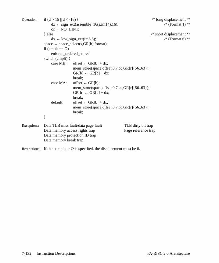
*/
Operation: if (d > 15 || d < -16) { /* long displacement */dx ← sign_ext(assemble_16(s,im14),16); /* (Format 1) cc ← NO_HINT;
} else /* short displacement */dx ← low_sign_ext(im5,5); /* (Format 6) */
space← space_select(s,GR[b],format);if (cmplt == O)
enforce_ordered_store;switch (cmplt) {
case MB: offset← GR[b] + dx;mem_store(space,offset,0,7,cc,GR[r]{56..63});GR[b] ← GR[b] + dx;break;
case MA: offset← GR[b];mem_store(space,offset,0,7,cc,GR[r]{56..63});GR[b] ← GR[b] + dx;break;
default: offset← GR[b] + dx;mem_store(space,offset,0,7,cc,GR[r]{56..63});break;
}
Exceptions: Data TLB miss fault/data page fault TLB dirty bit trapData memory access rights trap Page reference trapData memory protection ID trapData memory break trap
Restrictions: If the completerO is specified, the displacement must be 0.
7-132 Instruction Descriptions PA-RISC 2.0 Architecture

igned
ivenword
stding)es theline is
teient to
ordbytebyte in
pleter
firstre as if
Store Bytes STBY
Format: STBY,cmplt,cc r,d(s,b)
(6)
Purpose: To implement the beginning, middle, and ending cases for fast byte moves with unalsources and destinations.
Description: If the PSW E-bit is 0 and begin (modifier ",B" corresponding toa = 0) is specified, therightmost bytes of GRr are stored in memory starting at the byte whose address is gby the effective address. The number of bytes stored is sufficient to fill out the containing the byte addressed by the effective address.
If the PSW E-bit is 0 and end (modifier ",E" corresponding toa = 1) is specified, theleftmost bytes of the rightmost word of GRr are stored in memory starting at the leftmobyte in the word specified by the effective address, and continuing until (but not incluthe byte specified by the effective address. When the effective address specifileftmost byte in a word, nothing is stored, but protection is checked and the cache marked asdirty.
If the PSW E-bit is 1 and begin (modifier ",B" corresponding toa = 0) is specified, theleftmost bytes of the rightmost word of GRr are stored in memory starting at the bywhose address is given by the effective address. The number of bytes stored is sufficfill out the word containing the byte addressed by the effective address.
If the PSW E-bit is 1 and end (modifier ",E" corresponding toa = 1) is specified, therightmost bytes of GRr are stored in memory starting at the leftmost byte in the wspecified by the effective address, and continuing until (but not including) the specified by the effective address. When the effective address specifies the leftmost a word, nothing is stored, but protection is checked and the cache line is marked asdirty.
If base register modification is specified through completer ",M", GRb is updated and thentruncated to a word address. (Table 7-7 defines the assembly language commnemonics.) If base register modification is specified andb = r, the value stored at theeffective address is the bytes from the source register before modification.
Table 7-7. Store Bytes Instruction Completers
The completer,cc, specifies the cache control hint (see Table 6-8 on page 6-10.) If thebyte of the addressed cache line is not written to, the processor must perform the sto
03 b r s a 1 cc C m im5
6 5 5 2 1 1 2 4 1 5
cmplt Description a m
<none> or B Beginning case, don’t modify base register 0 0B,M Beginning case, Modify base register 0 1E Ending case, don’t modify base register 1 0E,M Ending case, Modify base register 1 1
7-133PA-RISC 2.0 Architecture Instruction Descriptions

tion
ring
the cache control hint had not been specified.
Operation: space← space_select(s,GR[b],format);dx ← low_sign_ext(im5,5);if (cmplt == B,M) /*a=0, m=1*/
offset ← GR[b];else
offset ← GR[b] + dx;pos ← 8*(offset & 0x3);offset ← offset & ~0x3; /* word aligned */switch (cmplt) {
case B: /*a=0, m=0*/if (PSW[E] == 0)
mem_store(space,offset,pos,31,cc,GR[r]{pos+32..63});else
mem_store(space,offset,pos,31,cc,GR[r]{32..63-pos});break;
case E: /*a=1, m=0*/if (PSW[E] == 0)
mem_store(space,offset,0,pos-1,cc,GR[r]{32..pos+31});else
mem_store(space,offset,0,pos-1,cc,GR[r]{64-pos..63});break;
case B,M: /*a=0, m=1*/if (PSW[E] == 0)
mem_store(space,offset,pos,31,cc,GR[r]{pos+32..63});else
mem_store(space,offset,pos,31,cc,GR[r]{32..63-pos});GR[b] ← (GR[b] + dx) & ~0x3;break;
case E,M: /*a=1, m=1*/if (PSW[E] == 0)
mem_store(space,offset,0,pos-1,cc,GR[r]{32..pos+31});else
mem_store(space,offset,0,pos-1,cc,GR[r]{64-pos..63});GR[b] ← (GR[b] + dx) & ~0x3;break;
}
Exceptions: Data TLB miss fault/data page fault TLB dirty bit trapData memory access rights trap Page reference trapData memory protection ID trap Data memory break trap
Notes: All bits of the original virtual offset are saved, unmasked, to IOR (CR21) if this instructraps.
For this instruction, the low 2 bits of the virtual offset are masked to 0 when compa
7-134 Instruction Descriptions PA-RISC 2.0 Architecture

le
against the contents of the data breakpoint address offset registers.
Programming NoteTheSTBY instruction with the ’,E’ completer and the effective address specifying the leftmostbyte of the word may be used to implement a memory scrubbing operation. This is possibbecause the line is markeddirty but the contents are not modified.
7-135PA-RISC 2.0 Architecture Instruction Descriptions

ed asgfield.
baseon andr thel
e
ss
Store Doubleword STD
Format: STD,cmplt,cc r,d(s,b)
(3)
(6)
Purpose: To store a doubleword from a general register.
Description: GR r is stored in the aligned doubleword at the effective address. The offset is formthe sum of a base register,b, and a displacementd. The displacement can be either lon(Format 3) or short (Format 6.) The displacement is encoded into the immediate Optional base modification can also be performed.
The completer,cmplt, determines whether the offset is the base register, or the register plus the displacement. The completer also specifies base register modificatiordering constraints (see Table H-1 on page H-4, and Table H-3 on page H-8 foassembly language completer mnemonics.) The completer,cc, specifies the cache controhint (see Table 6-8 on page 6-10.)
For long and short displacements, a one in them field specifies base modification, and tha field encodes whether pre-modification (a=1), or post-modification (a=0) is performed.
If base register modification is specified andb = r, the value stored at the effective addreis the word from the source register before modification.
1C b r s im10a m a 0 i
6 5 5 2 10 1 1 1 1
03 b r s a 1 cc B m im5
6 5 5 2 1 1 2 4 1 5
7-136 Instruction Descriptions PA-RISC 2.0 Architecture

) */
may
Operation: if (d > 15 || d < -16) { /* long displacement */dx ← sign_ext(assemble_16a(s,cat(im10a,0),i),16); /* (Format 3cc ← NO_HINT;
} else /* short displacement */dx ← low_sign_ext(im5,5); /* (Format 6) */
space← space_select(s,GR[b],format);if (cmplt == O)
enforce_ordered_store;switch (cmplt) {
case MB: offset← GR[b] + dx;mem_store(space,offset,0,63,cc,GR[r]);GR[b] ← GR[b] + dx;break;
case MA: offset← GR[b];mem_store(space,offset,0,63,cc,GR[r]);GR[b] ← GR[b] + dx;break;
default: offset← GR[b] + dx;mem_store(space,offset,0,63,cc,GR[r]);break;
}
Exceptions: Data TLB miss fault/data page fault Data memory break trapData memory access rights trap TLB dirty bit trapData memory protection ID trap Page reference trapUnaligned data reference trap
Restrictions: For long displacements (Format 3), only displacements which are multiples of eightbe used.
If the completerO is specified, the displacement must be 0.
7-137PA-RISC 2.0 Architecture Instruction Descriptions
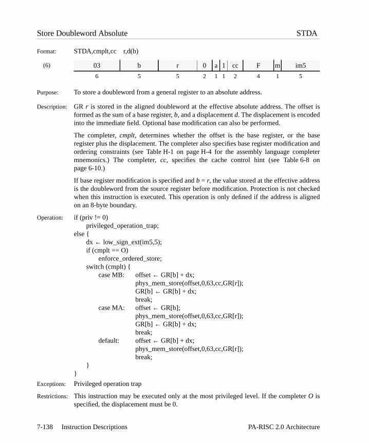
set isd
baseon andpleteron
sscked
igned
Store Doubleword Absolute STDA
Format: STDA,cmplt,cc r,d(b)
(6)
Purpose: To store a doubleword from a general register to an absolute address.
Description: GR r is stored in the aligned doubleword at the effective absolute address. The offformed as the sum of a base register,b, and a displacementd. The displacement is encodeinto the immediate field. Optional base modification can also be performed.
The completer,cmplt, determines whether the offset is the base register, or the register plus the displacement. The completer also specifies base register modificatiordering constraints (see Table H-1 on page H-4 for the assembly language commnemonics.) The completer,cc, specifies the cache control hint (see Table 6-8 page 6-10.)
If base register modification is specified andb = r, the value stored at the effective addreis the doubleword from the source register before modification. Protection is not chewhen this instruction is executed. This operation is only defined if the address is alon an 8-byte boundary.
Operation: if (priv != 0)privileged_operation_trap;
else {dx ← low_sign_ext(im5,5);if (cmplt == O)
enforce_ordered_store;switch (cmplt) {
case MB: offset← GR[b] + dx;phys_mem_store(offset,0,63,cc,GR[r]);GR[b] ← GR[b] + dx;break;
case MA: offset← GR[b];phys_mem_store(offset,0,63,cc,GR[r]);GR[b] ← GR[b] + dx;break;
default: offset← GR[b] + dx;phys_mem_store(offset,0,63,cc,GR[r]);break;
}}
Exceptions: Privileged operation trap
Restrictions: This instruction may be executed only at the most privileged level. If the completerO isspecified, the displacement must be 0.
03 b r 0 a 1 cc F m im5
6 5 5 2 1 1 2 4 1 5
7-138 Instruction Descriptions PA-RISC 2.0 Architecture

igned
ivenword
he) theftmostline is
n byword
he) theftmostline is
nguage
firstre as if
Store Doubleword Bytes STDBY
Format: STDBY,cmplt,cc r,d(s,b)
(6)
Purpose: To implement the beginning, middle, and ending cases for fast byte moves with unalsources and destinations.
Description: If the PSW E-bit is 0 and begin (modifier ",B" corresponding toa = 0) is specified, therightmost bytes of GRr are stored in memory starting at the byte whose address is gby the effective address. The number of bytes stored is sufficient to fill out the doublecontaining the byte addressed by the effective address.
If the PSW E-bit is 0 and end (modifier ",E" corresponding toa = 1) is specified, theleftmost bytes of GRr are stored in memory starting at the leftmost byte in tdoubleword specified by the effective address, and continuing until (but not includingbyte specified by the effective address. When the effective address specifies the lebyte in a doubleword, nothing is stored, but protection is checked and the cache marked asdirty.
If the PSW E-bit is 1 and begin (modifier ",B" corresponding toa = 0) is specified, theleftmost bytes of GRr are stored in memory starting at the byte whose address is givethe effective address. The number of bytes stored is sufficient to fill out the doublecontaining the byte addressed by the effective address.
If the PSW E-bit is 1 and end (modifier ",E" corresponding toa = 1) is specified, therightmost bytes of GRr are stored in memory starting at the leftmost byte in tdoubleword specified by the effective address, and continuing until (but not includingbyte specified by the effective address. When the effective address specifies the lebyte in a doubleword, nothing is stored, but protection is checked and the cache marked asdirty.
If base register modification is specified through completer ",M", GRb is updated and thentruncated to a doubleword address (see Table 7-7 on page 7-133 for the assembly lacompleter mnemonics.) If base register modification is specified andb = r, the value storedat the effective address is the bytes from the source register before modification.
The completer,cc, specifies the cache control hint (see Table 6-8 on page 6-10.) If thebyte of the addressed cache line is not written to, the processor must perform the stothe cache control hint had not been specified.
03 b r s a 1 cc D m im5
6 5 5 2 1 1 2 4 1 5
7-139PA-RISC 2.0 Architecture Instruction Descriptions

tion
ring
Operation: space← space_select(s,GR[b],format);dx ← low_sign_ext(im5,5);if (cmplt == B,M) /*a=0, m=1*/
offset ← GR[b];else
offset ← GR[b] + dx;pos ← 8*(offset & 0x7);offset ← offset & ~0x7; /* doubleword aligned */switch (cmplt) {
case B: /*a=0, m=0*/if (PSW[E] == 0)
mem_store(space,offset,pos,63,cc,GR[r]{pos..63});else
mem_store(space,offset,pos,63,cc,GR[r]{0..63-pos});break;
case E: /*a=1, m=0*/if (PSW[E] == 0)
mem_store(space,offset,0,pos-1,cc,GR[r]{0..pos-1});else
mem_store(space,offset,0,pos-1,cc,GR[r]{64-pos..63});break;
case B,M: /*a=0, m=1*/if (PSW[E] == 0)
mem_store(space,offset,pos,63,cc,GR[r]{pos..63});else
mem_store(space,offset,pos,63,cc,GR[r]{0..63-pos});GR[b] ← (GR[b] + dx) & ~0x7;break;
case E,M: /*a=1, m=1*/if (PSW[E] == 0)
mem_store(space,offset,0,pos-1,cc,GR[r]{0..pos-1});else
mem_store(space,offset,0,pos-1,cc,GR[r]{64-pos..63});GR[b] ← (GR[b] + dx) & ~0x7;break;
}
Exceptions: Data TLB miss fault/data page fault TLB dirty bit trapData memory access rights trap Page reference trapData memory protection ID trapData memory break trap
Notes: All bits of the original virtual offset are saved, unmasked, to IOR (CR21) if this instructraps.
For this instruction, the low 3 bits of the virtual offset are masked to 0 when compaagainst the contents of the data breakpoint address offset registers.
7-140 Instruction Descriptions PA-RISC 2.0 Architecture

n.
Programming NoteThe STDBY instruction with the ’,E’ completer and the effective address specifying theleftmost byte of the doubleword may be used to implement a memory scrubbing operatioThis is possible because the line is markeddirty but the contents are not modified.
7-141PA-RISC 2.0 Architecture Instruction Descriptions

ss.
ent is.
baseon andr thel
ss
Store Halfword STH
Format: STH,cmplt,cc r,d(s,b)
(1)
(6)
Purpose: To store a halfword from a general register.
Description: The rightmost halfword in GRr is stored in the aligned halfword at the effective addreThe offset is formed as the sum of a base register,b, and a displacementd. Thedisplacement can be either long (Format 1) or short (Format 6.) The displacemencoded into the immediate field. Optional base modification can also be performed
The completer,cmplt, determines whether the offset is the base register, or the register plus the displacement. The completer also specifies base register modificatiordering constraints (see Table H-1 on page H-4, and Table H-3 on page H-8 foassembly language completer mnemonics.) The completer,cc, specifies the cache controhint (see Table 6-8 on page 6-10.)
For short displacements, a one in them field specifies base modification, and thea fieldencodes whether pre-modification (a=1), or post-modification (a=0) is performed.
If base register modification is specified andb = r, the value stored at the effective addreis the halfword from the source register before modification.
19 b r s im14
6 5 5 2 14
03 b r s a 1 cc 9 m im5
6 5 5 2 1 1 2 4 1 5
7-142 Instruction Descriptions PA-RISC 2.0 Architecture

*/
Operation: if (d > 15 || d < -16) { /* long displacement */dx ← sign_ext(assemble_16(s,im14),16); /* (Format 1) cc ← NO_HINT;
} else /* short displacement */dx ← low_sign_ext(im5,5); /* (Format 6) */
space← space_select(s,GR[b],format);if (cmplt == O)
enforce_ordered_store;switch (cmplt) {
case MB: offset← GR[b] + dx;mem_store(space,offset,0,15,cc,GR[r]{48..63});GR[b] ← GR[b] + dx;break;
case MA: offset← GR[b];mem_store(space,offset,0,15,cc,GR[r]{48..63});GR[b] ← GR[b] + dx;break;
default: offset← GR[b] + dx;mem_store(space,offset,0,15,cc,GR[r]{48..63});break;
}
Exceptions: Data TLB miss fault/data page fault Data memory break trapData memory access rights trap TLB dirty bit trapData memory protection ID trap Page reference trapUnaligned data reference trap
Restrictions: If the completerO is specified, the displacement must be 0.
7-143PA-RISC 2.0 Architecture Instruction Descriptions

he
ed into
baseon andr thel
B) isd. For
ss
Store Word STW
Format: STW,cmplt,cc r,d(s,b)
(1)
(2)
(6)
Purpose: To store a word from a general register.
Description: The rightmost word in GRr is stored in the aligned word at the effective address. Toffset is formed as the sum of a base register,b, and a displacementd. The displacementcan be either long (Formats 1 and 2) or short (Format 6.) The displacement is encodthe immediate field. Optional base modification can also be performed.
The completer,cmplt, determines whether the offset is the base register, or the register plus the displacement. The completer also specifies base register modificatiordering constraints (see Table H-1 on page H-4, and Table H-3 on page H-8 foassembly language completer mnemonics.) The completer,cc, specifies the cache controhint (see Table 6-8 on page 6-10.)
For long displacements with pre-decrement or post-increment, Format 1 (opcode 1used. For long displacements with post-decrement or pre-increment, Format 2 is uselong displacements with no base modification, Format 1 (opcode 1A) is used.
For short displacements, a one in them field specifies base modification, and thea fieldencodes whether pre-modification (a=1), or post-modification (a=0) is performed.
If base register modification is specified andb = r, the value stored at the effective addreis the word from the source register before modification.
1A/1B b r s im14
6 5 5 2 14
1F b r s im11a 2 i
6 5 5 2 11 2 1
03 b r s a 1 cc A m im5
6 5 5 2 1 1 2 4 1 5
7-144 Instruction Descriptions PA-RISC 2.0 Architecture

*/
*/
only
Operation: if (d > 15 || d < -16) { /* long displacement */if ((cmplt==MB && d>=0) || (cmplt==MA && d<0))
dx ← sign_ext(assemble_16a(s,im11a,i),16); /* (Format 2)else
dx ← sign_ext(assemble_16(s,im14),16); /* (Format 1) cc ← NO_HINT;
} else /* short displacement */dx ← low_sign_ext(im5,5); /* (Format 6) */
space← space_select(s,GR[b],format);if (cmplt == O)
enforce_ordered_store;switch (cmplt) {
case MB: offset← GR[b] + dx;mem_store(space,offset,0,31,cc,GR[r]{32..63});GR[b] ← GR[b] + dx;break;
case MA: offset← GR[b];mem_store(space,offset,0,31,cc,GR[r]{32..63});GR[b] ← GR[b] + dx;break;
default: offset← GR[b] + dx;mem_store(space,offset,0,31,cc,GR[r]{32..63});break;
}
Exceptions: Data TLB miss fault/data page fault Data memory break trapData memory access rights trap TLB dirty bit trapData memory protection ID trap Page reference trapUnaligned data reference trap
Restrictions: For post-decrement and pre-increment with long displacements (Format 2), displacements which are multiples of four may be used.
If the completerO is specified, the displacement must be 0.
7-145PA-RISC 2.0 Architecture Instruction Descriptions

ess.
lso be
baseon andpleteron
sswhenn a 4-
Store Word Absolute STWA
Format: STWA,cmplt,cc r,d(b)
(6)
Purpose: To store a word from a general register to an absolute address.
Description: The rightmost word in GRr is stored in the aligned word at the effective absolute addrThe offset is formed as the sum of a base register,b, and a displacementd. Thedisplacement is encoded into the immediate field. Optional base modification can aperformed.
The completer,cmplt, determines whether the offset is the base register, or the register plus the displacement. The completer also specifies base register modificatiordering constraints (see Table H-1 on page H-4 for the assembly language commnemonics.) The completer,cc, specifies the cache control hint (see Table 6-8 page 6-10.)
If base register modification is specified andb = r, the value stored at the effective addreis the word from the source register before modification. Protection is not checked this instruction is executed. This operation is only defined if the address is aligned obyte boundary.
Operation: if (priv != 0)privileged_operation_trap;
else {dx ← low_sign_ext(im5,5);if (cmplt == O)
enforce_ordered_store;switch (cmplt) {
case MB: offset← GR[b] + dx;phys_mem_store(offset,0,31,cc,GR[r]{32..63});GR[b] ← GR[b] + dx;break;
case MA: offset← GR[b];phys_mem_store(offset,0,31,cc,GR[r]{32..63});GR[b] ← GR[b] + dx;break;
default: offset← GR[b] + dx;phys_mem_store(offset,0,31,cc,GR[r]{32..63});break;
}}
Exceptions: Privileged operation trap
03 b r 0 a 1 cc E m im5
6 5 5 2 1 1 2 4 1 5
7-146 Instruction Descriptions PA-RISC 2.0 Architecture
Restrictions: This instruction may be executed only at the most privileged level. If the completerO isspecified, the displacement must be 0.
7-147PA-RISC 2.0 Architecture Instruction Descriptions
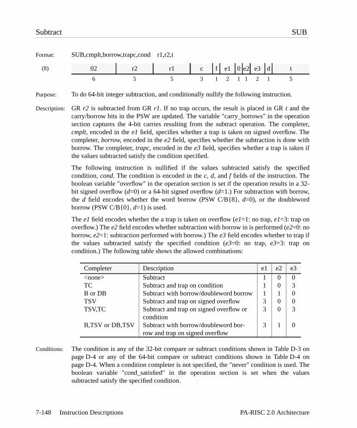
ationleter,he
ithif
fied
a 32-
f
3 on4 on. Thealues
Subtract SUB
Format: SUB,cmplt,borrow,trapc,cond r1,r2,t
(8)
Purpose: To do 64-bit integer subtraction, and conditionally nullify the following instruction.
Description: GR r2 is subtracted from GRr1. If no trap occurs, the result is placed in GRt and thecarry/borrow bits in the PSW are updated. The variable "carry_borrows" in the opersection captures the 4-bit carries resulting from the subtract operation. The compcmplt, encoded in thee1 field, specifies whether a trap is taken on signed overflow. Tcompleter,borrow, encoded in thee2 field, specifies whether the subtraction is done wborrow. The completer,trapc, encoded in thee3field, specifies whether a trap is taken the values subtracted satisfy the condition specified.
The following instruction is nullified if the values subtracted satisfy the specicondition,cond. The condition is encoded in thec, d, andf fields of the instruction. Theboolean variable "overflow" in the operation section is set if the operation results in bit signed overflow (d=0) or a 64-bit signed overflow (d=1.) For subtraction with borrow,the d field encodes whether the word borrow (PSW C/B{8},d=0), or the doublewordborrow (PSW C/B{0},d=1) is used.
Thee1 field encodes whether the a trap is taken on overflow (e1=1: no trap,e1=3: trap onoverflow.) Thee2 field encodes whether subtraction with borrow in is performed (e2=0: noborrow,e2=1: subtraction performed with borrow.) Thee3 field encodes whether to trap ithe values subtracted satisfy the specified condition (e3=0: no trap,e3=3: trap oncondition.) The following table shows the allowed combinations:
Conditions: The condition is any of the 32-bit compare or subtract conditions shown in Table D-page D-4 or any of the 64-bit compare or subtract conditions shown in Table D-page D-4. When a condition completer is not specified, the "never" condition is usedboolean variable "cond_satisfied" in the operation section is set when the vsubtracted satisfy the specified condition.
02 r2 r1 c f e1 0 e2 e3 d t
6 5 5 3 1 2 1 1 2 1 5
Completer Description e1 e2 e3
<none> Subtract 1 0 0TC Subtract and trap on condition 1 0 3B or DB Subtract with borrow/doubleword borrow 1 1 0TSV Subtract and trap on signed overflow 3 0 0TSV,TC Subtract and trap on signed overflow or
condition3 0 3
B,TSV or DB,TSV Subtract with borrow/doubleword bor-row and trap on signed overflow
3 1 0
7-148 Instruction Descriptions PA-RISC 2.0 Architecture

,DB
Operation: switch (borrow) {case B: res← GR[r1] +∼GR[r2] + PSW[C/B]{8};
break;case DB: res← GR[r1] +∼GR[r2] + PSW[C/B]{0};
break;default: res← GR[r1] +∼GR[r2] + 1;
break;}if (cmplt == TSV && overflow)
overflow_trap;else if (trapc == TC && cond_satisfied)
conditional_trap;else {
GR[t] ← res;PSW[C/B] ← carry_borrows;if (cond_satisfied) PSW[N]← 1;
}
Exceptions: Overflow trapConditional trap
Notes: When the ,B completer is specified, only 32-bit conditions are available. When thecompleter is specified, only 64-bit conditions are available.
7-149PA-RISC 2.0 Architecture Instruction Descriptions

ing
ue ison
bit
fied
a 32-
3 on. Thealues
Subtract from Immediate SUBI
Format: SUBI,cmplt,cond i,r,t
(9)
Purpose: To subtract a register from an immediate value and conditionally nullify the followinstruction.
Description: GR r is subtracted from the sign-extended immediate valuei. If no trap occurs, the result isplaced in GRt and the carry/borrow bits in the PSW are updated. The immediate valencoded into theim11 field. The variable "carry_borrows" in the operation secticaptures the 4-bit carries resulting from the subtract operation.
The completer,cmplt, encoded in thee1field, specifies whether a trap is taken on a 32-signed overflow (e1=0: no trap, nocmplt, e1=1: trap on 32-bit signed overflow,cmplt==TSV.)
The following instruction is nullified if the values subtracted satisfy the specicondition, cond. The condition is encoded in thec and f fields of the instruction. Theboolean variable "overflow" in the operation section is set if the operation results in bit signed overflow.
Conditions: The condition is any of the 32-bit compare or subtract conditions shown in Table D-page D-4. When a condition completer is not specified, the "never" condition is usedboolean variable "cond_satisfied" in the operation section is set when the vsubtracted satisfy the specified condition.
Operation: res ← low_sign_ext(im11,11) +∼GR[r] + 1;if (cmplt == TSV && overflow)
overflow_trap;else {
GR[t] ← res;PSW[C/B] ← carry_borrows;if (cond_satisfied) PSW[N]← 1;
}
Exceptions: Overflow trap
Programming NoteSUBTRACT FROM IMMEDIATE can be used to perform a logical NOT operation when codedas follows:
25 r t c f e1 im11
6 5 5 3 1 1 11
SUBI -1,r,t /* GR[t] ← ∼GR[r] all PSW[C/B] are set to ones */
7-150 Instruction Descriptions PA-RISC 2.0 Architecture

t of
ction
be
ust
Synchronize Caches SYNC
Format: SYNC
(33)
Purpose: To enforce program order of instruction execution.
Description: Any load, store, semaphore, cache flush, or cache purge instructions that follow theSYNCinstruction get executed only after all such instructions prior to theSYNC instruction havecompleted executing. On implementations which execute such instructions ousequence, this instruction enforces program ordering.
Operation: Enforce program order of memory references
Exceptions: None
Notes: In systems in which all memory references are performed in order, this instruexecutes as a null instruction.
Programming NoteThe minimum spacing that is guaranteed to work for "self-modifying code" is shown in thecode segment below. Since instruction prefetching is permitted, any data cache flushes mustseparated from any instruction cache flushes by aSYNC. This will ensure that the "new"instruction will be written to memory prior to any attempts at prefetching it as an instruction.
This sequence assumes a uniprocessor system. In a multiprocessor system, software mensure no processor is executing code which is in the process of being modified.
00 rv 0 rv 0 20 0
6 5 1 4 3 8 5
LDIL l%newinstr,rnewLDW r%newinstr(0,rnew),tempLDIL l%instr,rinstrSTW temp,r%instr(0,rinstr)FDC r%instr(0,rinstr)SYNCFIC r%instr(rinstr)SYNC
(at least seven instructions)instr . . .
7-151PA-RISC 2.0 Architecture Instruction Descriptions

cheh aree next
utes
Synchronize DMA SYNCDMA
Format: SYNCDMA
(33)
Purpose: To enforce DMA completion order.
Description: On implementations which can signal DMA completion prior to achieving cacoherence, this instruction enforces ordering. All cache coherence actions whicoutstanding as a consequence of prior DMA operations must be completed before thmemory access is performed.
Operation: Enforce DMA completion order
Exceptions: None
Notes: In systems in which all DMA operations are performed in order, this instruction execas a null instruction.
00 rv 1 rv 0 20 0
6 5 1 4 3 8 5
7-152 Instruction Descriptions PA-RISC 2.0 Architecture

n or
ned
-8itioniableecified
Unit Add Complement UADDCM
Format: UADDCM,trapc,cond r1,r2,t
(8)
Purpose: To individually compare corresponding sub-units of a doubleword for a greater-thaless-than-or-equal a relation.
Description: GR r1 is added to the one’s complement of GRr2. If no trap occurs, the result is placed iGR t. The following instruction is nullified if the values added satisfy the specificondition,cond. The completer,trapc, encoded in thee1field, specifies whether a trap istaken if the condition,cond, is satisfied by the values added (e1=2: no trap, nocmplt,e1=3: trap on condition,cmplt==TC.) The condition is encoded in thec, d, andf fields ofthe instruction.
Conditions: The conditioncond is any of the 32-bit unit conditions shown in Table D-11 on page Dor any of the 64-bit conditions shown in Table D-12 on page D-8. When a condcompleter is not specified, the "never" condition is used. The boolean var"cond_satisfied" in the operation section is set when the values added satisfy the spcondition.
Operation: res← GR[r1] +∼GR[r2];if (trapc == TC && cond_satisfied)
conditional_trap;else {
GR[t] ← res;if (cond_satisfied) PSW[N]← 1;
}
Exceptions: Conditional trap
Programming NoteUNIT ADD COMPLEMENT can be used to perform a logical NOT operation when coded asfollows:
UNIT ADD COMPLEMENT with the TC (Trap on Condition) completer can be used to checkdecimal validity and to pre-bias decimal numbers.ra contains the number to be checked andrt
02 r2 r1 c f 2 0 1 e1 d t
6 5 5 3 1 2 1 1 2 1 5
UADDCM 0,r,t /* GR[t] ← ∼GR[r] */
7-153PA-RISC 2.0 Architecture Instruction Descriptions

will contain the number plus the bias as result of theUADDCM operation.
NINES .equ X’99999999LDIL l%NINES,ninesLDO r%NINES(nines),ninesUADDCM,TC,SDC ra,nines,rt
7-154 Instruction Descriptions PA-RISC 2.0 Architecture

n
innitZ,e
tion is
Unit XOR UXOR
Format: UXOR,cond r1,r2,t
(8)
Purpose: To individually compare corresponding sub-units of two doublewords for equality.
Description: GR r1 and GRr2 are XORed and the result is placed in GRt. This instruction generatesunit conditions unlikeXOR which generates logical conditions. The following instructiois nullified if the values XORed satisfy the specified condition,cond. The condition isencoded in thec, d, andf fields of the instruction.
Conditions: The condition,cond, is any of the 32-bit unit conditions not involving carries shown Table D-11 on page D-8 ("never", SBZ, SHZ, TR, NBZ, NHZ) or any of the 64-bit uconditions not involving carries shown in Table D-12 on page D-8 (*, *SBZ, *SH*SWZ, *TR, *NBZ, *NHZ, *NWZ.) When a condition completer is not specified, th"never" condition is used. The boolean variable "cond_satisfied" in the operation secset when the values XORed satisfy the specified condition.
Operation: GR[t] ← xor(GR[r1], GR[r2]);if (cond_satisfied) PSW[N]← 1;
Exceptions: None
02 r2 r1 c f 0 1 1 2 d t
6 5 5 3 1 2 1 1 2 1 5
7-155PA-RISC 2.0 Architecture Instruction Descriptions

7 orleanfy the
Exclusive OR XOR
Format: XOR,cond r1,r2,t
(8)
Purpose: To do a 64-bit, bitwise exclusive OR.
Description: GR r1 and GRr2 are XORed and the result is placed in GRt. The following instruction isnullified if the values XORed satisfy the specified condition,cond. The condition isencoded in thec, d, andf fields of the instruction.
Conditions: The condition is any of the 32-bit logical conditions shown in Table D-9 on page D-any of the 64-bit logical conditions shown in Table D-10 on page D-7. The boovariable "cond_satisfied" in the operation section is set when the values XORed satisspecified condition.
Operation: GR[t] ← xor(GR[r1], GR[r2]);if (cond_satisfied) PSW[N]← 1;
Exceptions: None
02 r2 r1 c f 0 1 0 2 d t
6 5 5 3 1 2 1 1 2 1 5
7-156 Instruction Descriptions PA-RISC 2.0 Architecture

r
rove theegisterecutesn thetions,
scribeds to
cessor any ones of thisndingcessor
-pointtes the
ndard iserence to of this and the
-pointnd the copy
bers,t. Eachalizedgn bit,
8 Floating-point Coprocesso
The PA-RISC floating-point coprocessor is an assist processor that is added to a system to impsystem’s performance on floating-point operations. The floating-point coprocessor contains a rfile which is independent of the processor’s register file. The floating-point coprocessor exfloating-point instructions to perform arithmetic on this register file and to move data betweeregister file and memory. The architecture permits pipelined execution of floating-point instrucfurther increasing the system’s performance.
Floating-point instructions are implementations of the more general coprocessor instructions depreviously in Chapter 6, “Instruction Set Overview”. The floating-point coprocessor respondcoprocessor instructions with a coprocessor id equal to 0 and 1.
While the floating-point coprocessor is not required to execute instructions sequentially, the coproand processor must ensure that the instructions appear sequentially executed to the software. Attime, the processor and coprocessor may be operating on a number of instructions. For purposechapter, the current instruction is the instruction pointed to by the IA queues. The term peinstructions refers to instructions which have entered and left the IA queues, but which the coprois still executing.
The IEEE Standard
When used in this chapter, the term IEEE standard or simply the standard, refers to theIEEE Standardfor Binary Floating-Point Arithmetic, ANSI/IEEE Std 754-1985. PA-RISC fully conforms to therequirements of the IEEE floating-point standard and permits implementation of all IEEE floatingrecommendations. Where hardware is unable to fully implement the standard, software compleimplementation.
Though this chapter uses quotes from the IEEE standard as architecture, knowledge of the stanot necessary to understand the architecture. Whenever a quote of the standard contains a refanother part of the standard, the quote also contains an equivalent reference to a sectiondocument. In these quotes, a reference to the IEEE standard is enclosed in parentheses,equivalent reference to this document is enclosed in square brackets.
The Instruction Set
The floating-point instruction set consists of load and store instructions, and operations. Floatingload and store instructions copy both single-word and double-word data between memory afloating-point registers. Floating-point operations do arithmetic on the floating-point registers anddata between floating-point registers.
The floating-point coprocessor operates on single-word and double-word IEEE floating-point numas well as quad-word numbers, which are an implementation of the IEEE double-extended formatype of floating-point number may represent one of the following: a normalized number, a denormnumber, a zero, an infinity, or a NaN (Not a Number). These floating-point formats consist of a si
8-1PA-RISC 2.0 Architecture Floating-point Coprocessor

umbersd two’s a 64-
be used level
tire 64- or the
f the use
onal. either. The
cation
an exponent, and a fraction.
The instruction set also has operations that convert among the three formats of floating-point nand between floating-point numbers and single-word, double-word, and quad-word unsigned ancomplement integers, as well as an instruction which multiplies two 32-bit unsigned integers withbit unsigned integer result.
Coprocessor Registers
The coprocessor contains thirty-two 64-bit floating-point registers. These same 32 locations can as sixty-four 32-bit locations or as sixteen 128-bit locations. Instructions executing at any privilegemay read or write the floating-point registers. Double-word load/store operations access the enbit register; single-word load/stores access either the left portion of a 64-bit register, bits 0 to 31,right portion of a 64-bit register, bits 32 to 63.
By convention, a 32-bit floating-point register is identified by appending a suffix to the identifier o64-bit register within which it is contained. The suffix for the left hand side 32-bit register is ‘L’; theof this suffix is optional. The suffix for the right hand side 32-bit register is ‘R’; its use is not optiThus, for example, the left half of double-word register 13 (bits 0 to 31) would be referred to as13 or 13L; the right half of double-word register 13 (bits 32 to 63) would be referred to as 13Rspecification ‘L’ or ‘R’ for each register is encoded in the instructions that access these registers.
Table 8-1 illustrates the specification of single-word registers and Table 8-2 illustrates the specifiof double-word registers.
8-2 Floating-point Coprocessor PA-RISC 2.0 Architecture

Table 8-1. Single-Word Floating-Point Registers
Register Purpose
0 Status Register Undefined
1 Undefined Undefined
2 Undefined Undefined
3 Undefined Undefined
4 Floating-point register 4L Floating-point register 4R
5 Floating-point register 5L Floating-point register 5R
6 Floating-point register 6L Floating-point register 6R
7 Floating-point register 7L Floating-point register 7R
8 Floating-point register 8L Floating-point register 8R
9 Floating-point register 9L Floating-point register 9R
10 Floating-point register 10L Floating-point register 10R
11 Floating-point register 11L Floating-point register 11R
12 Floating-point register 12L Floating-point register 12R
13 Floating-point register 13L Floating-point register 13R
14 Floating-point register 14L Floating-point register 14R
15 Floating-point register 15L Floating-point register 15R
16 Floating-point register 16L Floating-point register 16R
17 Floating-point register 17L Floating-point register 17R
18 Floating-point register 18L Floating-point register 18R
19 Floating-point register 19L Floating-point register 19R
20 Floating-point register 20L Floating-point register 20R
21 Floating-point register 21L Floating-point register 21R
22 Floating-point register 22L Floating-point register 22R
23 Floating-point register 23L Floating-point register 23R
24 Floating-point register 24L Floating-point register 24R
25 Floating-point register 25L Floating-point register 25R
26 Floating-point register 26L Floating-point register 26R
27 Floating-point register 27L Floating-point register 27R
28 Floating-point register 28L Floating-point register 28R
29 Floating-point register 29L Floating-point register 29R
30 Floating-point register 30L Floating-point register 30R
31 Floating-point register 31L Floating-point register 31R
8-3PA-RISC 2.0 Architecture Floating-point Coprocessor

Status - 31R
ontain 63 of
Single-word register 0 contains the Status Register. Double-word registers 0 - 3 contain theRegister and the Exception Registers. Double-word registers 4 - 31 and single-word registers 4Rand 4L - 31L are data registers.
Registers 0 - 3 are partitioned into eight 32-bit registers. Bits 0 to 31 of double-word register 0 cthe Status Register, which holds information on rounding, compares, and exceptions. Bits 32 to
Table 8-2. Double-Word Floating-Point Registers
Register Purpose
0 Status Register Exception Register 1
1 Exception Register 2 Exception Register 3
2 Exception Register 4 Exception Register 5
3 Exception Register 6 Exception Register 7
4 Floating-point register 4
5 Floating-point register 5
6 Floating-point register 6
7 Floating-point register 7
8 Floating-point register 8
9 Floating-point register 9
10 Floating-point register 10
11 Floating-point register 11
12 Floating-point register 12
13 Floating-point register 13
14 Floating-point register 14
15 Floating-point register 15
16 Floating-point register 16
17 Floating-point register 17
18 Floating-point register 18
19 Floating-point register 19
20 Floating-point register 20
21 Floating-point register 21
22 Floating-point register 22
23 Floating-point register 23
24 Floating-point register 24
25 Floating-point register 25
26 Floating-point register 26
27 Floating-point register 27
28 Floating-point register 28
29 Floating-point register 29
30 Floating-point register 30
31 Floating-point register 31
8-4 Floating-point Coprocessor PA-RISC 2.0 Architecture

non-n used
form aption.
rd loadsa source
entireg andd other
rands..
these do not
63,
whichperation. Quad
double-word register 0 contain Exception Register 1. Specifying Floating-point Register 0 in aload/store operation encodes a floating-point +0 or a fixed-point 0, whichever is appropriate, wheas a source and is an undefined operation when used as a destination.
Double-word registers 1 to 3 contain the remaining exception registers. The exception registersqueue of instructions which could not normally complete and thus complete with a trapping exceThe exception registers are accessed using double-word load and store instructions. Single-woand stores of exception registers are undefined operations. Specifying an exception register as or destination of a non-load/store operation is undefined.
The entire state of the floating-point coprocessor is contained in the register file. Saving theregister file is sufficient for a context switch. A special instruction sequence allows the savinrestoring of this state without an interruption. This sequence ensures that context switches anoperations which affect the state of the coprocessor do not affect a process.
Data Registers
Floating-point registers 4 - 31 contain the 64-bit data registers which instructions use as opeSoftware may access these registers with single-word or double-word load and store instructions
Each of the floating-point data registers may contain values in a number of formats. The fields informats are packed into words, double-words, or quad-words so that load and store operationsrequire field-shuffling or tag bits.
Single-word formats occupy either the left half (bits 0 to 31, suffix ’L’), or the right half (bits 32 tosuffix ’R’) of a register as shown in Figure 8-1.
Double-word formats fill one register as shown in Figure 8-2.
Quad-word formats (128 bits) are packed into adjacent even-odd pairs of registers. An instructionreferences a register containing a quad-word value must name an even numbered register. An owhich specifies an odd numbered register for a quad-word format is an undefined operationformats are assembled in register pairs as shown in Figure 8-3.
0 31 32 63
single-word number (suffix L) single-word number (suffix R)
32 32
Figure 8-1. Single-word Data Format
double-word format
64
Figure 8-2. Double-word Data Format
8-5PA-RISC 2.0 Architecture Floating-point Coprocessor

fixed-
ds:
er of
umber,ust oneine the
Data Formats
Two data types are defined for floating-point coprocessor operations: floating-point formats andpoint formats.
Floating-point Formats
Numbers in the single, double, and quad binary floating-point formats are composed of three fiel
1. A 1-bit sign,s.
2. A biased exponent, .
3. A fraction, .
Note that adding thebias to the unbiased exponentE produces the biased exponente. The numbere isalways non-negative. Also,p is the precision of the number, and is equal to one plus the numbfraction bits. Figure 8-4 shows the positions of these fields in the registers.
Single Binary Floating-point
Double Binary Floating-point
Quad Binary Floating-point
For each floating-point format, a number may either be a normalized number, a denormalized nan infinity, a zero, or a NaN (Not a Number). Each representable nonzero numerical value has jencoding. Use the format parameters listed in Table 8-3 and the equations which follow to determrepresentation and value,v, of a floating-point number.
even # register most significant bits
odd # register least significant bits
64
Figure 8-3. Quad-word Data Format
s e fraction
1 8 23
s e fraction
1 11 52
s e high fraction
1 15 48
low fraction
64
Figure 8-4. Floating-point Formats
e E bias+=
f .b1b2…bp 1–=
8-6 Floating-point Coprocessor PA-RISC 2.0 Architecture

aN is
Zero: If and , then .
Denormalized: If and , then .
Normalized: If , then .
Infinity: If and , then .
NaN: If and , thenv is a NaN, regardless ofs.
If the number is a NaN, then the leftmost bit in the fraction, , determines whether the Nsignaling or quiet. If is 1, the NaN is a signaling NaN. If is 0, it is a quiet NaN.
NaNs are not ordered; neither the fraction nor the sign bits have any significance.
Fixed-Point Formats
Fixed-point values are held in the formats shown in Figure 8-5.
Table 8-3. Floating-Point Format Parameters
ParameterFormat
Single Double Quad
p (precision) 24 53 113
+127 +1023 +16383
−126 −1022 −16382
exponentbias +127 +1023 +16383
under/overflowbias-adjustment 192 1536 24576
exponent width in bits 8 11 15
format width in bits 32 64 128
E Emin 1–= f 0= v 1–( )s0=
E Emin 1–= f 0≠ v 1–( )s2
Emin 0. f( )=
Emin E Emax≤ ≤ v 1–( )s2
E1. f( )=
E Emax 1+= f 0= v 1–( )s∞=
E Emax 1+= f 0≠
b1b1 b1
EmaxEmin
8-7PA-RISC 2.0 Architecture Floating-point Coprocessor

dicatesidentifyg-point-word
r 0 in a, when
eue
. The
storeof the
Single Binary Fixed-point
Double Binary Fixed-point
Quad Binary Fixed-point
Floating-Point Status Register
The Status Register controls the arithmetic rounding mode, enables user-level traps, inexceptions that have occurred, indicates the results of comparisons, and contains information to the implementation of the coprocessor. The Status Register is located in bits 0 to 31 of FloatinRegister 0, and is accessed by specifying Floating-point Register 0 with single-word or doubleload and store instructions.
Non-load/store instructions do not access the Status Register. Specifying Floating-point Registenon-load/store operation, encodes a floating-point +0 or a fixed-point 0, whichever is appropriateused as a source and is an undefined operation when used as a destination.
Figure 8-6 shows the three formats of the Status Register. The first format is valid when theFLOATING-POINT COMPARE andFLOATING-POINT TEST instructions are being used to generate and test a quof comparison results. The second format is valid whenthe FLOATING-POINT COMPARE andFLOATING-POINT TEST instructions are being used to generate and test individual comparison bitsthird format is only valid immediately after the execution of aFLOATING-POINT IDENTIFY instruction.This format remains valid until a floating-point instruction is executed which is not a double-wordof Floating-point Register 0. The first or second format is valid thereafter. See the description FLOATING-POINT IDENTIFY instruction on page 9-9 for more information.
two’s complement integer
32
unsigned integer
32
two’s complement integer
64
unsigned integer
64
high two’s complement integer
low two’s complement integer
64
Figure 8-5. Fixed-point Formats
8-8 Floating-point Coprocessor PA-RISC 2.0 Architecture

each
hen anith a
ble bitts theentedion”ble 8-5
or setsrap. Aneption
Field Description
RM The rounding mode for all floating-point operations. The values corresponding to rounding mode are listed in Table 8-4.
Enables The exception trap enables. An enable bit is associated with each IEEE exception. Wenable bit equals 1, the corresponding trap is enabled. An instruction completes wdelayed trap when the instruction causes an exception whose corresponding enaequals 1. If an enable bit equals 0, the corresponding IEEE exception usually secorresponding exception flag to 1 instead of causing a trap. However, see “UnimplemException” on page 10-8, “Overflow Exception” on page 10-11, and “Underflow Excepton page 10-12 for cases when a trap is taken even when the trap is not enabled. Talists the bits that correspond to each IEEE exception.
Flags The exception flags. A flag bit is associated with each IEEE exception. The coprocessan exception flag to 1 when the corresponding exception occurs but does not cause a timplementation may also choose to set a flag bit to 1 when the corresponding exc
0 1 2 3 4 5 6 7 8 910 1 2 3 4 5 6 7 8 9
20 1 2 3 4 5 6 7 8 9
30 1
V Z O U I C un CQ RM un T D V Z O U I
0 1 2 3 4 5 6 7 8 910 1 2 3 4 5 6 7 8 9
20 1 2 3 4 5 6 7 8 9
30 1
V Z O U I un CA un RM un T D V Z O U I
0 1 2 3 4 5 6 7 8 910 1 2 3 4 5 6 7 8 9
20 1 2 3 4 5 6 7 8 9
30 1
un model revision un
Figure 8-6. Floating-Point Status Register
Table 8-4. Floating-Point Rounding Modes
Rounding mode Description
0 Round to nearest
1 Round toward zero
2 Round toward +∞3 Round toward−∞
Flags Enables
Flags Enables
8-9PA-RISC 2.0 Architecture Floating-point Coprocessor

parend 0 ifre
queued
t bit)is
of
d 0 ifre
eto
rd
e
s
efore
ts an
s and
occurs and causes a trap. An exception flag is never set to 0 as a side effect of floating-pointoperations, but it may be set to either 1 or 0 by a load instruction. Table8-5 lists the bits thatcorrespond to each IEEE exception.
C The Compare bit. The C-bit contains the result of the most recent queued cominstruction. This bit is set to 1 if the result of the most recent queued compare is true, afalse. The C-bit is undefined following a targeted compare. No other non-load/stoinstruction affects this bit, but it may be set to 1 or 0 by load instructions.
CQ The Compare Queue. The CQ field contains the results of the second-most recent compare (in CQ{0}) through the twelfth-most recent queued compare (in CQ{10}). Everyqueued compare instruction shifts the CQ field right by one bit (discarding the rightmosand the C-bit from the previous queued compare is copied into CQ{0}. The CQ field undefined following a targeted compare. No other non-load/store instruction affects thisfield, but it may be set to any value by load instructions.
CA The Compare Array. The CA field is an array of seven independent compare bits, each which contains the result of the most recent compare instruction targeting that bit. Anycompare targeting a particular bit sets that bit to 1 if the result of the compare is true, anfalse. The CA field is undefined following a queued compare. No other non-load/stoinstruction affects this field, but it may be set to any value by load instructions.
T The Delayed Trap bit. The coprocessor sets this bit to 1 when an IEEE exception occurs thatis signalled with a trap or when an unimplemented exception occurs. When this bit is 1, thcoprocessor is armed to trap, and the next floating-point instruction forces the processor take an assist exception trap. No non-load/store instructions affect this bit, but loadinstructions may set this bit to 1 or 0, and double-word stores of the Status Register set thisbit to 0 after completion of the store. Also, save and restore software uses this bit to recothe state of traps. See “Saving and Restoring State” on page 10-13 for information on stateswapping and “Interruptions and Exceptions” on page 10-4 for a detailed discussion of thT-bit’s operation.
D The Denormalized As Zero bit. The D-bit provides the arithmetic floating-point instructiona “fast mode” handling of denormalized operands and tiny results. When the D-bit is 1, anyof these instructions may optionally produce a correctly signed zero when the result, bor after rounding, lies between , and may optionally treat any denormalized operandas an equivalently signed zero. When the D-bit is 1, and an arithmetic instruction treaoperand as a zero, or produces a zero result as described above, the values of the Underflowand Inexact flags become undefined. When the D-bit is 0, all denormalized operand
Table 8-5. IEEE Exceptions
Bit Name Description
V Invalid operation
Z Division-by-zero
O Overflow
U Underflow
I Inexact result
2Emin±
8-10 Floating-point Coprocessor PA-RISC 2.0 Architecture

for the
ations.cifies ao the 32-bitoint
ssist
ad andoating-
. These
tiny results must be handled as described in the remainder of this chapter.
Implementation of the D-bit is optional; if not implemented, it is a nonexistent bit.
model The implementation-dependent model number. Model number zero (0) is reserved software emulation routines.
revision The implementation-dependent revision number.
un Undefined bits.
Floating-Point Instruction Set
The floating-point instruction set consists of load and store instructions, and floating-point operAll these instructions are part of the PA-RISC standard instruction set. When the instruction speregister for double precision and 64-bit fixed-point values, a 5-bit encoding maps directly intassociated floating-point register. When the instruction specifies a register for single-precision orfixed-point values, a 6-bit encoding maps into the appropriate ‘L’ or ‘R’ single-word floating-pregister.
Instruction Validity
Table 8-6 shows which floating-point instructions are defined, undefined, or will take an AEmulation Trap for various values of the uid field and the Coprocessor Configuration Register.
Load and Store Instructions
The floating-point load and store instructions are implementations of the PA-RISC coprocessor lostore instructions described in “Coprocessor Instructions” on page 6-22. Table 8-7 shows the flpoint load and store instructions.
The load and store instructions transfer data between the floating-point registers and memory
Table 8-6. Floating-Point Instruction Validity
OpcodeCCR{0..1}
0 1, 2 3
0B/0C trap undefined uid=0: defineduid=1: undefined
06/09/0E/26 trap undefined defined
Table 8-7. Floating-Point Load and Store Instructions
Mnemonic Description
FLDW Load wordFLDD Load doublewordFSTW Store wordFSTD Store doubleword
8-11PA-RISC 2.0 Architecture Floating-point Coprocessor

a basen index control
of aof thees an
oating-.
load or
sor tohoseto all
set the
ithmetic
tegoryuctions
-pointopcode
-points of the
hmetic
instructions transfer aligned words or aligned double-words, and form an effective address usingregister plus either a short displacement value, a long displacement value, or the value of aregister. They also have completers that specify base register modification, ordering, and cachehints.
Single-word loads and stores access either bits 0 to 31 (suffix ‘L’) or bits 32 to 63 (suffix ‘R’)register. The ability to specify more than 32 locations is accomplished by the use of bit 25 instruction. A 0 in this bit specifies an access of bits 0 to 31 (left half of the register); a 1 specifiaccess of bits 32 to 63 (the right half of the register). However, single-word loads and stores of flpoint registers 0R (the right half of floating-point register 0), 1, 2, and 3 are undefined operations
Double-word loads and stores can access any of the floating-point registers and may be used tostore a pair of single-word values in the left and right halves of a register.
A single-word or double-word load or store of Floating-point Register 0 forces the coprocescomplete all pending floating-point instructions and signal all floating-point exceptions for tinstructions. Additionally, a double-word store of Floating-point Register 0 cancels traps due previous instructions and, after completion of the store, sets the Status Register T-bit to 0.
Single-word stores of register 0 do not cancel traps. Also, single-word loads of register 0 that Status Register T-bit to 1 are undefined operations.
Load and store instructions may cause a number of memory reference traps. They are not arinstructions and do not cause IEEE exceptions.
Load and store instructions that access the I/O address space are defined operations.
Floating-point Operations
There are three categories of floating-point operation instructions. Each instruction in the first caperforms a single operation. Instructions in the second category perform fused operations. Instrin the third category perform multiple operations.
Single-operation Instructions
This section describes the single-operation floating-point instructions. Single-operation floatinginstructions are encoded using two major opcodes - 0C and 0E. Most of the functions in the 0C are also duplicated in the 0E opcode with the following exceptions:
• Instructions using the 0E opcode can address both the left and right halves of the floatingregister set whereas the instructions using the 0C opcode can only address the left halvefloating-point register set.
• TheFLOATING-POINT IDENTIFY andFLOATING-POINT TEST instructions are available only in the0C opcode.
• The format completer for the quad-word data type is available only in the 0C opcode.
• TheFIXED-POINT MULTIPLY UNSIGNED instruction is available only in the 0E opcode.
There are four classes of operations:
• Class 0 contains single source, single destination operations and includes the non-arit
8-12 Floating-point Coprocessor PA-RISC 2.0 Architecture

al 0.
at
operations.
• Class 1 consists of the conversion operations.
• Class 2 operations provide mechanisms to compare two operands.
• Class 3 consists of the arithmetic operations with two sources and one destination.
Figure 8-7 shows the format of these operations.
Floating-point operation class zero: 1 source, 1 destination*
Floating-point operation class one: 1 source, 1 destination
Floating-point operation class two: 2 sources, no destination*
Floating-point operation class three: 2 sources, 1 destination†
* The FLOATING-POINT IDENTIFY andFLOATING-POINT TEST instructions have no sourceor destination operands, and no format specifiers, so the register and format fields equ
† TheFIXED-POINT MULTIPLY UNSIGNED instruction has no format specifier, so the formfield equals 0.
0C r 0 sub fmt 0 0 0 t
6 5 5 3 2 2 3 1 5
0E r 0 sub 0 f 0 0 r t 0 t
6 5 5 3 1 1 2 1 1 1 1 5
0C r 0 sub df sf 1 0 0 t
6 5 3 3 2 2 2 3 1 5
0E r 0 sub 0 df 0 sf 1 0 r t 0 t
6 5 3 3 1 1 1 1 2 1 1 1 1 5
0C r1 r2 sub fmt 2 0 n c
6 5 5 3 2 2 3 1 5
0E r1 r2 sub r2 f 2 0 r1 0 0 c
6 5 5 3 1 1 2 1 1 1 1 5
0C r1 r2 sub fmt 3 0 0 t
6 5 5 3 2 2 3 1 5
0E r1 r2 sub r2 f 3 x r1 t 0 t
6 5 5 3 1 1 2 1 1 1 1 5
8-13PA-RISC 2.0 Architecture Floating-point Coprocessor
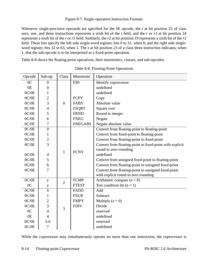
single-en
ssor is
Figure 8-7. Single-operation Instruction Formats
Whenever single-precision operands are specified for the 0E opcode, thet at bit position 25 of classzero, one, and three instructions represents a sixth bit of thet field, and ther or r1 at bit position 24represents a sixth bit of ther or r1 field. Similarly, ther2 at bit position 19 represents a sixth bit of ther2field. These bits specify the left side single-word register, bits 0 to 31, when 0, and the right side word register, bits 32 to 63, when 1. Thex at bit position 23 of a class three instruction indicates, wh1, that the sub-opcode is to be interpreted as a fixed-point operation.
Table 8-8 shows the floating-point operations, their mnemonics, classes, and sub-opcodes.
While the coprocessor may simultaneously operate on more than one instruction, the coproce
Table 8-8. Floating-Point Operations
Opcode Sub-op Class Mnemonic Operation
0C 0
0
FID Identify coprocessor0E 0 undefined
0C/0E 1 undefined0C/0E 2 FCPY Copy0C/0E 3 FABS Absolute value0C/0E 4 FSQRT Square root0C/0E 5 FRND Round to integer0C/0E 6 FNEG Negate0C/0E 7 FNEGABS Negate absolute value0C/0E 0
1 FCNV
Convert from floating-point to floating-point0C/0E 1 Convert from fixed-point to floating-point0C/0E 2 Convert from floating-point to fixed-point0C/0E 3 Convert from floating-point to fixed-point with explicit
round to zero rounding0C/0E 4 undefined0C/0E 5 Convert from unsigned fixed-point to floating-point0C/0E 6 Convert from floating-point to unsigned fixed-point0C/0E 7 Convert from floating-point to unsigned fixed-point
with explicit round to zero rounding0C/0E y
2FCMP Arithmetic compare (n = 0)
0C y FTEST Test condition bit (n = 1)0C/0E 0
3
FADD Add0C/0E 1 FSUB Subtract0C/0E 2 FMPY Multiply (x = 0)0C/0E 3 FDIV Divide
0C 4 reserved0E 4 undefined
0C/0E 5-6 reserved0C/0E 7 undefined
8-14 Floating-point Coprocessor PA-RISC 2.0 Architecture

-point
ctions
ver
ept for
using.
and 0E
e of a
sourceingle-, in thennot be their
restricted by the number of exception registers to executing no more than seven floatingoperations at one time.
All the operations which have at least one floating-point operand are considered arithmetic instruand will generate an invalid exception when operating on a signaling NaN, except for theFLOATING-POINT NEGATE, FLOATING-POINT NEGATE ABSOLUTE VALUE, FLOATING-POINT COPY, andFLOATING-POINT ABSOLUTE VALUE instructions, which are considered non-arithmetic and negenerate any IEEE exceptions.
TheFLOATING-POINT IDENTIFY andFLOATING-POINT TEST instructions do not cause exceptions.
Table 8-9 shows the only fixed-point operation, its mnemonic, class and sub-opcode.
Operand Format Completers
For class 0, 2 and 3 operations, except forFIXED-POINT MULTIPLY UNSIGNED, the source anddestination widths are the same and the instructions operate only on floating-point numbers. Excthe FLOATING-POINT IDENTIFY, FLOATING-POINT TEST, andFIXED-POINT MULTIPLY UNSIGNEDoperations, each has an accompanying completer which specifies the data width the operation is
Table 8-10 shows the instruction completers and their corresponding format codes for the 0C opcodes.
The Code field above indicates the encoding corresponding to each completer. The absenccompleter specifies a single-word number. An operation with aCode value of 2 is an undefinedoperation. In the 0E opcode, onlyCode values 0 and 1 can be specified.
The operations in class 1 (the conversion instructions) have two completers which specify the and destination formats independently. However, the floating-point to floating-point conversions sto-single and double-to-double in the 0C and 0E opcodes are undefined operations; In addition0C opcode, quad-to-quad floating-point conversion is an undefined operation (quad precision caspecified in the 0E opcode). Table 8-11 shows the conversion instruction completers and
Table 8-9. Fixed-Point Operations
Opcode Sub-op x-bit Class Mnemonic Operation
0E 2 1 3 XMPYU Fixed-point Multiply Unsigned
Table 8-10. Single-Operation Instruction Format Completers
Opcode Mnemonic Code Description Data Size
0C/0E <none> 0 single-word number 32 bits0C/0E SGL 0 single-word number 32 bits0C/0E DBL 1 double-word number 64 bits
0C QUAD 3 quad-word number 128 bits0C 2 undefined
8-15PA-RISC 2.0 Architecture Floating-point Coprocessor

theE
tion
corresponding format codes.
TheCode field above indicates the encoding corresponding to each completer, which appears insfanddf fields of the instruction. An operation with aCode value of 2 is an undefined operation. In the 0opcode, onlyCode values 0 and 1 can be specified.
Comparison Conditions
TheFLOATING-POINT COMPARE instruction has an additional completer which indicates the condibeing tested. These conditions are listed in Table 8-12 which is derived from the IEEE standard.
Table 8-11. Conversion Instruction Format Completers
Opcode Mnemonic Code Description Data Size
0C/0ESGL
0single-word floating-point
32 bitsW single-word signed integerUW single-word unsigned integer
0C/0EDBL
1double-word floating-point
64 bitsDW double-word signed integerUDW double-word unsigned integer
0CQUAD
3quad-word floating-point
128 bitsQW quad-word signed integerUQW quad-word unsigned integer
0C 2 undefined
Table 8-12. Floating-Point Compare Instruction Conditions
ConditionRelations
Code ConditionRelations
Code> < = unordered > < = unordered
false? F F F F 0 !?<= T F F F 16
false F F F F * 1 > T F F F * 17
? F F F T 2 ?> T F F T 18
!<=> F F F T * 3 !<= T F F T * 19
= F F T F 4 !?< T F T F 20
=T F F T F * 5 >= T F T F * 21
?= F F T T 6 ?>= T F T T 22
!<> F F T T * 7 !< T F T T * 23
!?>= F T F F 8 !?= T T F F 24
< F T F F * 9 <> T T F F * 25
?< F T F T 10 != T T F T 26
!>= F T F T * 11 !=T T T F T * 27
!?> F T T F 12 !? T T T F 28
<= F T T F * 13 <=> T T T F * 29
?<= F T T T 14 true? T T T T 30
!> F T T T * 15 true T T T T * 31
8-16 Floating-point Coprocessor PA-RISC 2.0 Architecture

of fourst caseperand,
pares.
tatusuction
(see thehiftedit in a true
ds are causes
gister 1, the
-point has anted in
Comparisons are exact and neither overflow or underflow. Between any two operands, one mutually exclusive relations is possible: less than, equal, greater than, and unordered. The laarises when at least one operand is a NaN. Every NaN compares unordered with every oincluding itself. Comparisons ignore the sign of zero, so +0 is equal to -0.
In the table above,Condition is the condition mnemonic used in the assembly language andCode is themachine language encoding.
There are two types of floating-point compare instructions – targeted compares and queued com
• A targeted compare targets a specific bit of the compare array (CA) in the floating-point SRegister (see the second format in Figure 8-6 on page 8-9). The CA-bit specified by the instris set to the result in the appropriate relations column, 1 for a true result, 0 for false.
• A queued compare updates the compare queue (CQ) in the floating-point Status Register first format in Figure 8-6 on page 8-9). The CQ field in the floating-point Status Register is sright by one bit (discarding the rightmost bit) and the C-bit is copied into CQ{0}. Then, the C-bthe floating-point Status Register is set to the result in the appropriate relations column, 1 forresult, 0 for false.
The asterisk (*) indicates that the instruction causes an invalid operation exception if its operanunordered. However, if at least one operand is a signaling NaN, the compare instruction alwaysan invalid operation exception.
Test Conditions
There are two types ofFLOATING-POINT TEST instructions – targeted tests and queue tests.
• A targeted test tests a specific bit of the compare array (CA) in the floating-point Status Re(see the second format in Figure 8-6 on page 8-9). If the CA-bit specified by the instruction isPSW[N] bit is set to 1. No condition may be specified for a targeted test.
• A queue test tests for a specific condition in the C-bit and compare queue (CQ) in the floatingStatus Register (see the first format in Figure 8-6 on page 8-9). Each queue test instructionadditional completer which indicates the condition being tested. These conditions are lisTable 8-13. If the condition being tested is true, the PSW[N] bit is set to 1.
8-17PA-RISC 2.0 Architecture Floating-point Coprocessor

ltiplya two- input
randands ofdd
n the
Fused-Operation Instructions
The floating-point instruction set includes instructions which perform a fused floating-point muand add operation. Fused-operation instructions are four-operand instructions which perform input multiply whose intermediate result is optionally negated and is then added to the thirdoperand. This final result is then rounded and placed in the destination register. That is: dest← ±(op1 *op2) + op3. These instructions are encoded using the 2E opcode.
The format of the fused-operation instructions is as follows:
Therm1, rm2, andt fields specify the two source operands for the multiply and the destination opefor the final result. These fields occupy the same positions within the instruction word as the opera class 3 single-operation floating-point instruction. Thera field specifies the source operand for the aoperation.
Table 8-14 lists the two fused-operation instructions, their mnemonics and sub-ops (encoded ie
Table 8-13. Floating-Point Test Instruction Conditions
Completer Description Condition Code
<none> Simple Test C == 1 0ACC Graphics (12-bit) Trivial Accept C == 0 && CQ{0..10} == 0 1ACC8 Graphics 8-bit Trivial Accept C == 0 && CQ{0..6} == 0 5ACC6 Graphics 6-bit Trivial Accept C == 0 && CQ{0..4} == 0 9ACC4 Graphics 4-bit Trivial Accept C == 0 && CQ{0..2} == 0 13ACC2 Graphics 2-bit Trivial Accept C == 0 && CQ{0} == 0 17REJ Graphics (12-bit) Trivial Reject C == 1 && CQ{5} == 1 ||
CQ{0} == 1 && CQ{6} == 1 ||CQ{1} == 1 && CQ{7} == 1 ||CQ{2} == 1 && CQ{8} == 1 ||CQ{3} == 1 && CQ{9} == 1 ||CQ{4} == 1 && CQ{10} == 1
2
REJ8 Graphics 8-bit Trivial Reject C == 1 && CQ{3} == 1 ||CQ{0} == 1 && CQ{4} == 1 ||CQ{1} == 1 && CQ{5} == 1 ||CQ{2} == 1 && CQ{6} == 1
6
2E rm1 rm2 ra r2 f ra r1 t e t
6 5 5 3 1 1 3 1 1 1 5
Figure 8-8. Fused-Operation Instruction Format
8-18 Floating-point Coprocessor PA-RISC 2.0 Architecture

Only is the
ndentine a
r theerands
o
Only given
field).
The f field in the floating-point fused-operation instructions is the operand format completer. single-word and double-word formats are supported. The interpretation of the format completersame as for the single-operation 0E opcode instructions as given in Table 8-10 on page 8-15.
Multiple-Operation Instructions
The floating-point instruction set includes instructions which perform more than one indepefloating-point operation. Multiple-operation instructions are five-operand instructions which combthree-operand multiply with a two-operand operation (ADD or SUB) of the form: dest← dest <op>source. These instructions are encoded using the 06 and 26 opcodes.
The format of the multiple-operation instructions is as follows:
The rm1, rm2, and tm fields specify the two source operands and the destination operand fomultiply operation. These fields occupy the same positions within the instruction word as the opof a class 3 single-operation floating-point instruction. Thera and ta fields specify source anddestination operands for the ALU operation.
The behavior of the multiple-operation instructions is undefined ifra specifies the same register astm,or if ta specifies the same register as any ofrm1, rm2, or tm. The behavior of these instructions is alsundefined ifra specifies double-precision register 0 or single-precision register 16L.
Table 8-15 lists the two multiple-operation instructions, their mnemonics and opcodes.
The f field in the floating-point multiple-operation instructions is the operand format completer. single-word and double-word formats are supported. The interpretation of the format completer is
Table 8-14. Fused-Operation Instructions
Sub-op Mnemonic Operation
0 FMPYFADD Multiply Fused Add1 FMPYNFADD Multiply Negate Fused Add
op rm1 rm2 ta ra f tm
6 5 5 5 5 1 5
Figure 8-9. Multiple-Operation Instruction Format
Table 8-15. Multiple-Operation Instructions
Opcode Mnemonic Operation
06 FMPYADD Multiply/Add26 FMPYSUB Multiply/Subtract
8-19PA-RISC 2.0 Architecture Floating-point Coprocessor

t
these Whene single- top 16uction
in Table 8-16.
NOTENote that the instruction format completers for the multiple-operation instructions do nofollow the same pattern as those for the single-operation and fused-operation instructions.
Because the floating-point multiple-operation instructions have only five-bit operand specifiers,instructions operate on only 32 locations, even when the single-word data format is specified.double-word data is specified, the interpretation of these operand specifiers is the same as for thoperation instructions. For single-word data, however, the operand specifiers are restricted to theregisters (32 locations). The details of the interpretation of the operand specifier field in the instrare shown in Table 8-17.
Table 8-16. Multiple-Operation Instruction Format Completers
Mnemonic Code Description Data Size
<none> or SGL 1 single-word number 32 bitsDBL 0 double-word number 64 bits
8-20 Floating-point Coprocessor PA-RISC 2.0 Architecture

Table 8-17. Single-Precision Operand Specifier Use in Multi-Operation Instructions
Register specifierfield in instruction
Register selected
0 16L*
16 16R
1 17L
17 17R
2 18L
18 18R
3 19L
19 19R
4 20L
20 20R
5 21L
21 21R
6 22L
22 22R
7 23L
23 23R
8 24L
24 24R
9 25L
25 25R
10 26L
26 26R
11 27L
27 27R
12 28L
28 28R
13 29L
29 29R
14 30L
30 30R
15 31L
31 31R
*not allowed
8-21PA-RISC 2.0 Architecture Floating-point Coprocessor

in”d
”tehe
ese
asiseith
]
e
NOTE
The L/R Select bit in the single-word format specifies the suffix ‘L’ single-word register, bits 0to 31, when 0, and the suffix ‘R’ single-word register, bits 32 to 63, when 1.
Rounding
The specification for the rounding operation from the IEEE standard is:
Rounding takes a number regarded as infinitely precise and, if necessary, modifies it to fit the destination’s format while signaling the inexact exception (7.5) [see “Inexact Exceptionon page 10-10]. Except for binary-decimal conversion (whose weaker conditions are specifiein 5.6 [not included]), every operation specified in Section 5 [see “Floating-point Operationson page 8-12] shall be performed as if it first produced an intermediate result correct to infiniprecision and with unbounded range, and then rounded that result according to one of tmodes in this section.
The rounding modes affect all arithmetic operations except comparison. The rounding modmay affect the signs of zero sums (6.3) [see “Sign Bit” on page 8-24], and do affect ththresholds beyond which overflow (7.3) [see “Overflow Exception” on page 10-11] andunderflow (7.4) [see “Underflow Exception” on page 10-12] may be signaled.
[§]4.1 Round to nearest. An implementation of this standard shall provide round to nearest the default rounding mode. In this mode the representable value nearest to the infinitely precresult shall be delivered; if the two nearest representable values are equally near, the one wits least-significant bit zero shall be delivered. However, an infinitely precise result with
magnitude at least shall round to∞ with no change in sign; here and
p are determined by the destination format (§3) [see “Floating-point Formats” on page 8-6unless overridden by a rounding precision mode (4.3) [not possible in PA-RISC].
[§]4.2 Directed Roundings. An implementation shall also provide three user-selectabldirected rounding modes: round toward +∞, round toward−∞, and round toward 0. Whenrounding toward +∞, the result shall be the format’s value (possibly +∞) closest to and no lessthan the infinitely precise result. When rounding toward−∞, the result shall be the format’s
Double-word Format
n n n n n
Operand Specifier
n n n n n
Register File Address
Single-word Format
n n n n n
Operand Specifier
1 n n n n
Register File Address
L/R Select
(assumed) 1
2Emax 2 2
p––( ) Emax
8-22 Floating-point Coprocessor PA-RISC 2.0 Architecture

he
return a
entedption
tr’s
ds.
nd then if an
urns aa quiet
invalideration
0. Ifnd bitoption in the
value (possibly−∞) closest to and no greater than the infinitely precise result. When roundingtoward 0, the result shall be the format’s value closest to and no greater in magnitude than tinfinitely precise result.
TheRM field in the Status Register determines the rounding mode.
While the above IEEE quote describes the process of rounding, an operation does not always rounded result. The result of an operation may be affected if the operation causes an exception.
Infinity Arithmetic
From the standard:
[§]6.1 Infinity Arithmetic. Infinity arithmetic shall be construed as the limiting case of realarithmetic with operands of arbitrarily large magnitude, when such a limit exists. Infinitiesshall be interpreted in the affine sense, that is:
Arithmetic with an infinite operand is always exact and can only signal invalid and unimplemexceptions. An infinite result is created from finite operands only by a non-trapping overflow exceor a non-trapping division-by-zero exception.
Operations With NaNs
From the standard:
[§]6.2 Operations with NaNs. Two different kinds of NaN, signaling and quiet, shall besupported in all operations. Signaling NaNs afford values for uninitialized variables andarithmetic-like enhancements (such as complex-affine infinities or extremely wide range) thaare not the subject of the standard. Quiet NaNs should, by means left to the implementodiscretion, afford retrospective diagnostic information inherited from invalid or unavailabledata and results. Propagation of the diagnostic information requires that information containein the NaNs be preserved through arithmetic operations and floating-point format conversion
An operation causes an invalid exception when at least one operand is a signaling NaN aoperation is any arithmetic operation. Also, certain compare operations cause an invalid exceptiooperand is a quiet NaN. See “Comparison Conditions” on page 8-16 for more detail.
Converting either a quiet or a signaling NaN to an integer format causes an invalid exception.
A NaN is created in two ways. Any operation that causes a non-trapping invalid exception retquiet NaN. Otherwise, an operation returns a quiet NaN when at least one of its operands is NaN, and the operation is any arithmetic operation.
An operation converts a signaling NaN to a quiet NaN when the operation causes a non-trappingexception and one of its operands is a signaling NaN. If both operands are signaling NaNs, the opconverts the contents of the first operand (ther1 register).
An operation which converts a signaling NaN to a quiet NaN sets the first bit of the fraction ( ) tothe remaining bits in the fraction are all zeros ( ), the operation must set the secoin the fraction to 1. Otherwise, if the remainder of the fraction is not 0, an implementation has the of setting the second bit in the fraction to 1, or leaving it unchanged. Only the first and second bits
∞– every finite number( ) +∞< <
b1b2…bp 1– 0=
8-23PA-RISC 2.0 Architecture Floating-point Coprocessor

its are
copies
nd sets
-pointif theo 1 toerts aaller
af a.
es
fraction may change when creating a quiet NaN from a signaling NaN. The remaining fraction bcopied from the signaling NaN.
When one of its operands is a quiet NaN, but neither operand is a signaling NaN, an operationthe quiet NaN to the destination. If both operands are quiet NaNs, ther1 register is copied to thedestination.
The creation of a quiet NaN when neither input is a NaN sets the second fraction bit ( ) to 1 aeach of the remaining fraction bits to 0.
A conversion operation which does not trap, and which converts a NaN to a smaller floatingformat, preserves the most-significant portion of the fraction while returning a quiet NaN. But most-significant portion of the fraction is all zeros, the second bit of the fraction must be set tprevent the number from becoming an infinity. A conversion which does not trap, and which convNaN to a larger floating-point format, augments the fraction with zeros to the right of the smfraction while returning a quiet NaN.
Load and store instructions, as well as theFLOATING-POINT NEGATE, FLOATING-POINT NEGATEABSOLUTE VALUE, FLOATING-POINT COPY, andFLOATING-POINT ABSOLUTE VALUE instructions,are not arithmetic and do not signal an invalid operation exception.
Sign Bit
From the standard:
[§]6.3 The sign bit. This standard does not interpret the sign of a NaN. Otherwise the sign ofproduct or quotient is the exclusive OR of the operands’ signs; and the sign of the sum, or odifference regarded as a sum , differs from at most one of the addends’ signsThese rules shall apply even when operands or results are zero or infinite.
When the sum of two operands with opposite signs (or the difference of two operands with liksigns) is exactly zero, the sign of that sum (or difference) shall be "+" in all rounding modeexcept round toward−∞, in which mode the sign shall be "−". However,retains the same sign asx even whenx is zero.
Except that shall be "−0", every valid square root shall have positive sign.
b2
x y– x y–( )+
x x+ x x–( )–=
0–
8-24 Floating-point Coprocessor PA-RISC 2.0 Architecture
t
oint -
oint
ont of
or theated in
9 Floating-Point Instruction Se
This chapter provides a description of each of the instructions supported by the floating-pcoprocessor. The instructions are listed in alphabetical order, according to the name of the instructionas opposed to the instruction mnemonic.
The Description section of each non-load/store instruction contains a list of the Floating-PExceptions which the instruction may cause. Each instruction description has an Exceptions sectionwhich lists the processor interruptions that may occur while the instruction is pointed to by the frthe IA queues.
In the following pages, the notation, FPR, refers to floating-point coprocessor registers 0 through 31.FPSR refers to the Floating-point Status Register. Refer to “Instruction Notations” on page xviii fexplanation of the operation section. The mem_load and the mem_store descriptions are loc“Memory Reference Instructions” on page6-6.
9-1PA-RISC 2.0 Architecture Floating-Point Instruction Set
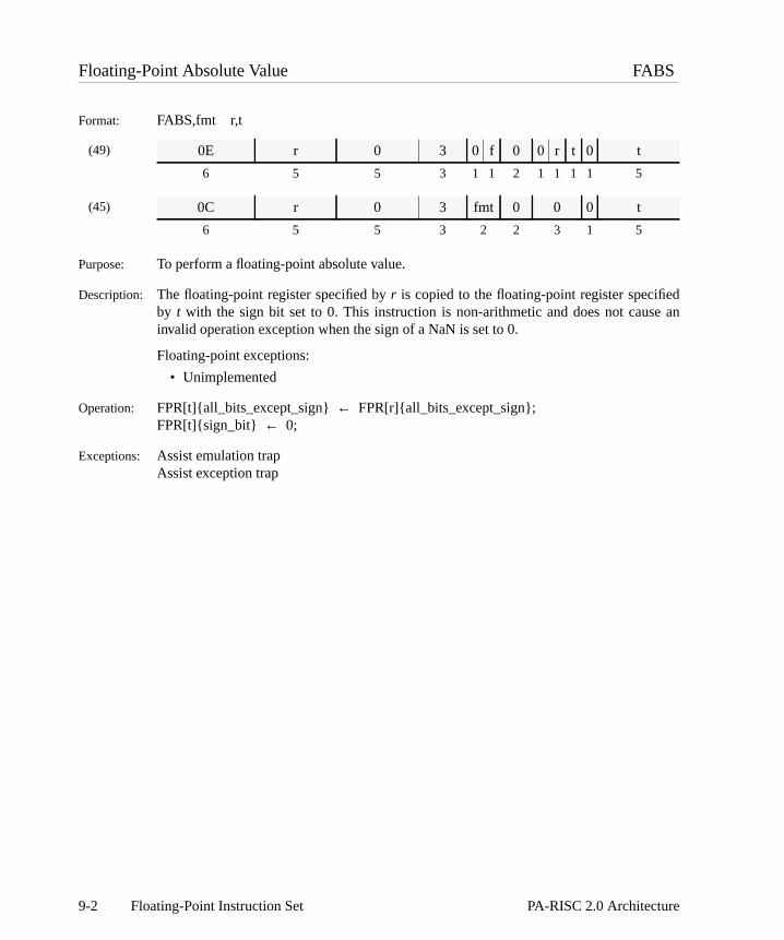
de an
Floating-Point Absolute Value FABS
Format: FABS,fmt r,t
(49)
(45)
Purpose: To perform a floating-point absolute value.
Description: The floating-point register specified byr is copied to the floating-point register specifieby t with the sign bit set to 0. This instruction is non-arithmetic and does not causinvalid operation exception when the sign of a NaN is set to 0.
Floating-point exceptions:
• Unimplemented
Operation: FPR[t]{all_bits_except_sign}← FPR[r]{all_bits_except_sign};FPR[t]{sign_bit} ← 0;
Exceptions: Assist emulation trapAssist exception trap
0E r 0 3 0 f 0 0 r t 0 t
6 5 5 3 1 1 2 1 1 1 1 5
0C r 0 3 fmt 0 0 0 t
6 5 5 3 2 2 3 1 5
9-2 Floating-Point Instruction Set PA-RISC 2.0 Architecture

ted toin the
Floating-Point Add FADD
Format: FADD,fmt r1,r2,t
(52)
(48)
Purpose: To perform a floating-point addition.
Description: The floating-point registers specified byr1 andr2 are interpreted in the specified formaand arithmetically added. The result is calculated to infinite precision and then roundthe specified format according to the current rounding mode. The result is placed floating-point register specified byt.
Floating-point exceptions:
• Unimplemented
• Invalid operation
• Overflow
• Underflow
• Inexact
Operation: FPR[t] ← FPR[r1] + FPR[r2];
Exceptions: Assist emulation trapAssist exception trap
0E r1 r2 0 r2 f 3 0 r1 t 0 t
6 5 5 3 1 1 2 1 1 1 1 5
0C r1 r2 0 fmt 3 0 0 t
6 5 5 3 2 2 3 1 5
9-3PA-RISC 2.0 Architecture Floating-Point Instruction Set

//
td the
and
ting-A-bitThe
tatusittingt bytheto 1,
N and
d CA
cifiedhe
sive
Floating-Point Compare FCMP
Format: FCMP,fmt,cond r1,r2,cbit /*targeted compare*FCMP,fmt,cond r1,r2 /*queued compare*
(51)
(47)
Purpose: To perform a floating-point comparison.
Description: The floating-point registers specified byr1 andr2 are interpreted in the specified formaand arithmetically compared. A result is determined based on the comparison ancondition,cond. The condition is encoded in thec field of the instruction.
There are two types of floating-point compare instructions – targeted comparesqueued compares.
• A targeted compare targets a specific bit of the compare array (CA) in the floapoint Status Register (see the second format in Figure 8-6 on page 8-9.) The Cspecified bycbit is set to 1 if the comparison result is true, or set to 0 otherwise. CA-bit to set is encoded in they field of the instruction ascbit + 1.
• A queued compare updates the compare queue (CQ) in the floating-point SRegister (see the first format in Figure 8-6 on page 8-9) and is specified by omthecbit operand. The CQ field in the floating-point Status Register is shifted righone bit (discarding the rightmost bit) and the C-bit is copied into CQ{0}. Then, if comparison result is true, the C-bit in the floating-point Status Register is set otherwise the C-bit is set to 0. A queued compare is encoded with ay field of 0.
If at least one of the values is a signaling NaN, or if at least one of the values is a Nathe low-order bit of the condition is 1, an invalid operation exception is signaled.
For unimplemented and trapped invalid operation exceptions, the state of the C-bit anfield is unchanged, and the CQ field is not shifted.
For untrapped invalid operation exceptions, the state of the C-bit, or the CA-bit speby the instruction is the AND of the unordered relation (which is true) and bit 3 of tcfield.
Comparisons are exact and neither overflow nor underflow. Four mutually exclurelations are possible results:less than, equal, greater than, andunordered. The last casearises when at least one operand is a NaN. Every NaN comparesunordered witheverything, including itself. Comparisons ignore the sign of zero, so .
0E r1 r2 y r2 f 2 0 r1 0 0 c
6 5 5 3 1 1 2 1 1 1 1 5
0C r1 r2 y fmt 2 0 0 c
6 5 5 3 2 2 3 1 5
+0 0–=
9-4 Floating-Point Instruction Set PA-RISC 2.0 Architecture

Floating-point exceptions:
• Unimplemented
• Invalid operation
Operation: if (NaN(FPR[r1]) || NaN(FPR[r2]))if (c{4})
invalid_operation_exception;else {
greater_than← false;less_than← false;equal_to← false;unordered← true;
}else {
greater_than← FPR[r1] > FPR[r2];less_than← FPR[r1] < FPR[r2];equal_to← FPR[r1] = FPR[r2];unordered← false;
}if (y) { /*targeted compare*/
FPSR[CA{y–1}] ← (((c{0} == 1) && greater_than) ||((c{1} == 1) && less_than) ||((c{2} == 1) && equal_to) ||((c{3} == 1) && unordered));
} else { /*queued compare*/FPSR[CQ] ← rshift(FPSR[CQ],1);FPSR[CQ{0}] ← FPSR[C];FPSR[C] ← (((c{0} == 1) && greater_than) ||
((c{1} == 1) && less_than) ||((c{2} == 1) && equal_to) ||((c{3} == 1) && unordered));
}
Exceptions: Assist emulation trapAssist exception trap
9-5PA-RISC 2.0 Architecture Floating-Point Instruction Set

e and
d theently
.
Floating-Point Convert FCNV
Format: FCNV,sf,df r,tFCNV,t,sf,df r,t
(50)
(46)
Purpose: To change the value in a floating-point register from one format to a different format.
Description: The floating-point register specified byr is interpreted in the specified source format,sf,and arithmetically converted to the specified destination format,df. The result is placed inthe floating-point register specified byt.
Thesf anddf completers specify both the type of conversion and the size of the sourcdestination formats, and are encoded in thesub, sf, anddf fields of the instruction (seeTable 8-8 on page 8-14 and Table 8-11 on page 8-16.)
If the “,t” (truncate) completer is specified, the current rounding mode is ignored anresult is rounded toward zero. Otherwise, rounding occurs according to the currspecified rounding mode.
Floating-point exceptions:
• Unimplemented
• Invalid operation
• Overflow*
• Underflow*
• Inexact* Not reported unless both source and destination formats are floating-point formats
Operation: if (truncate)FPR[t] ← convert(FPR[r],sf,df,ROUND_TOWARD_ZERO);
elseFPR[t] ← convert(FPR[r],sf,df,FPSR[RM]);
Exceptions: Assist emulation trapAssist exception trap
Restrictions: The“,t” completer may only be specified with a fixed-point destination format.
Specifying the same source and destination format is an undefined operation.
Specifying any quadword format in the 0E opcode is an undefined operation.
0E r 0 sub 0 df 0 sf 1 0 r t 0 t
6 5 3 3 1 1 1 1 2 1 1 1 1 5
0C r 0 sub df sf 1 0 0 t
6 5 3 3 2 2 2 3 1 5
9-6 Floating-Point Instruction Set PA-RISC 2.0 Architecture

dption
Floating-Point Copy FCPY
Format: FCPY,fmt r,t
(49)
(45)
Purpose: To copy a floating-point value to another floating-point register.
Description: The floating-point register specified byr is copied into the floating-point register specifieby t. This operation is non-arithmetic and does not cause an invalid operation excewhen a NaN is copied.
Floating-point exceptions:
• Unimplemented
Operation: FPR[t] ← FPR[r];
Exceptions: Assist emulation trapAssist exception trap
0E r 0 2 0 f 0 0 r t 0 t
6 5 5 3 1 1 2 1 1 1 1 5
0C r 0 2 fmt 0 0 0 t
6 5 5 3 2 2 3 1 5
9-7PA-RISC 2.0 Architecture Floating-Point Instruction Set

tnded in the
Floating-Point Divide FDIV
Format: FDIV,fmt r1,r2,t
(52)
(48)
Purpose: To perform a floating-point division.
Description: The floating-point registers specified byr1 andr2 are interpreted in the specified formaand arithmetically divided. The result is calculated to infinite precision and then routo the specified format according to the current rounding mode. The result is placedfloating-point register specified byt.
Floating-point exceptions:
• Unimplemented
• Invalid operation
• Division-by-zero
• Overflow
• Underflow
• Inexact
Operation: FPR[t] ← FPR[r1] / FPR[r2];
Exceptions: Assist emulation trapAssist exception trap
0E r1 r2 3 r2 f 3 0 r1 t 0 t
6 5 5 3 1 1 2 1 1 1 1 5
0C r1 r2 3 fmt 3 0 0 t
6 5 5 3 2 2 3 1 5
9-8 Floating-Point Instruction Set PA-RISC 2.0 Architecture

f the. The
ed
btain
ly not,
ccursdl trap)
Floating-Point Identify FID
Format: FID
(45)
Purpose: To validate fields in the Status Register which identify the floating-point coprocessor.
Description: Themodel andrevision fields in the Status Register become defined. The contents oother fields in the Status Register are undefined after the execution of this instructionmodel and revision fields remain defined until a floating-point instruction is executwhich is not a double-word store of register 0.
Floating-point exceptions:
• None
Operation: FPSR[model]← implementation-dependent model number;FPSR[revision]← implementation-dependent revision number;
Exceptions: Assist emulation trap
Notes: This instruction must be implemented. Software may use the following sequence to othemodel andrevision fields in the Status Register:
For the FID instruction to work correctly, the floating-point instructions immediatepreceding and following it must be double-word stores of Floating-Point Register 0. Ifthe instruction is an undefined operation.
The sequence described will work in user mode. For example, if a context switch ojust prior toFID but after the firstFSTD 0,0(2) instruction, the floating-point state save anstate restore sequence will restore the state of the Status Register ("T" bit off, cancejust prior to the execution ofFID.
0C 0 0 0 0 0 0 0 0
6 5 5 3 2 2 3 1 5
.CODE
LDIL L%fpreg0,r2 ; load address ofLDO R%fpreg0(r2),r2 ; fp reg0 save areaFSTD fr0,0(r2) ; save fp reg0, cancel exception traps
FID ; identify coprocessor
LDIL L%version,r2 ; load address ofLDO R%version(r2),r2 ; model/rev save areaFSTD fr0,0(r2) ; store coprocessor id, cancel
; exception traps
.DATA
fpreg0 .DOUBLE 0version .DOUBLE 0
9-9PA-RISC 2.0 Architecture Floating-Point Instruction Set

41.)n also
baseegister1 onnics.)
e
vious
Floating-Point Load Doubleword FLDD
Format: FLDD,cmplt,cc x|d(s,b),t
(3)
(41)
(39)
Purpose: To load a doubleword into a floating-point coprocessor register.
Description: The aligned doubleword at the effective address is loaded into floating-point registert. Theoffset is formed as the sum of a base register,b, and either an index register,x (Format 39),or a displacementd. The displacement can be either long (Format 3) or short (FormatThe displacement is encoded into the immediate field. Optional base modification cabe performed.
The completer,cmplt, determines whether the offset is the base register, or the register plus the index register or displacement. The completer also specifies base rmodification, optional index prescaling, and ordering constraints (see Table H-page H-4, and Table H-3 on page H-8 for the assembly language completer mnemoThe completer,cc, specifies the cache control hint (see Table 6-7 on page 6-10.)
For long and short displacements, a one in them field specifies base modification, and tha field encodes whether pre-modification (a=1), or post-modification (a=0) is performed.For indexed loads, a one in them field specifies base modification, and a one in theu fieldspecifies index prescaling.
Specifying Floating-Point Register 0 forces the coprocessor to complete all prefloating-point instructions.
14 b t s im10a m a 1 i
6 5 5 2 10 1 1 1 1
0B b im5 s a 1 cc 0 0 0 m t
6 5 5 2 1 1 2 1 2 1 1 5
0B b x s u 0 cc 0 0 0 m t
6 5 5 2 1 1 2 1 2 1 1 5
9-10 Floating-Point Instruction Set PA-RISC 2.0 Architecture

/) */
es of
Operation: if (indexed_load) /* indexed (Format 39)*/switch (cmplt) {
case S:case SM: dx← lshift(GR[x],3);
break;case M:default: dx← GR[x];
break;}
else if (d > 15 || d < -16) { /* long displacement *dx ← sign_ext(assemble_16a(s,cat(im10a,0),i),16); /* (Format 3cc ← NO_HINT;
} else /* short displacement */dx ← low_sign_ext(im5,5); /* (Format 41) */
space← space_select(s,GR[b],format);switch (cmplt) {
case MB: offset← GR[b] + dx;GR[b] ← GR[b] + dx;break;
case MA:case M:case SM: offset← GR[b];
GR[b] ← GR[b] + dx;break;
default: offset← GR[b] + dx;break;
}FPR[t] ← mem_load(space,offset,0,63,cc);if (cmplt == O)
enforce_ordered_load;
Exceptions: Assist exception trap Unaligned data reference trapData TLB miss fault/data page fault Page reference trapData memory access rights trap Assist emulation trapData memory protection ID trap
Restrictions: For loads with long displacements (Format 3), only displacements which are multipleight may be used.
If the completerO is specified, the displacement must be 0.
9-11PA-RISC 2.0 Architecture Floating-Point Instruction Set

rmatn can
baseegister1 onnics.)
nedte allth a
Floating-Point Load Word FLDW
Format: FLDW,cmplt,cc x|d(s,b),t
(43)
(44)
(41)
(39)
Purpose: To load a word into a floating-point coprocessor register.
Description: The aligned word at the effective address is loaded into floating-point registert. The offsetis formed as the sum of a base register,b, and either an index register,x (Format 39), or adisplacementd. The displacement can be either long (Formats 43 and 44) or short (Fo41.) The displacement is encoded into the immediate field. Optional base modificatioalso be performed.
The completer,cmplt, determines whether the offset is the base register, or the register plus the index register or displacement. This completer also specifies base rmodification, optional index prescaling, and ordering constraints (see Table H-page H-4, and Table H-3 on page H-8 for the assembly language completer mnemoThe completer,cc, specifies the cache control hint (see Table 6-7 on page 6-10.)
For long displacements with base modification, Format 44 is used, and thea field encodeswhether pre-modification (a=1), or post-modification (a=0) is performed. For longdisplacements with no base modification, Format 43 is used.
For short displacements, a one in them field specifies base modification, and thea fieldencodes whether pre-modification (a=1), or post-modification (a=0) is performed. Forindexed loads, a one in them field specifies base modification, and a one in theu fieldspecifies index prescaling.
Specifying floating-point registers 0R, 1L, 1R, 2L, 2R, 3L, or 3R is an undefioperation. Specifying Floating-Point Register 0L forces the coprocessor to compleprevious floating-point instructions. However, loading Floating-Point Register 0L wivalue that sets the Status Register T-bit to 1 is an undefined operation.
17 b t s im11a 0 t i
6 5 5 2 11 1 1 1
16 b t s im11a a t i
6 5 5 2 11 1 1 1
09 b im5 s a 1 cc 0 0 t m t
6 5 5 2 1 1 2 1 2 1 1 5
09 b x s u 0 cc 0 0 t m t
6 5 5 2 1 1 2 1 2 1 1 5
9-12 Floating-Point Instruction Set PA-RISC 2.0 Architecture

/) */
h are
Operation: if (indexed_load) /* indexed (Format 39)*/switch (cmplt) {
case S:case SM: dx← lshift(GR[x],2);
break;case M:default: dx← GR[x];
break;}
else if (d > 15 || d < -16) { /* long displacement *dx ← sign_ext(assemble_16a(s,im11a,i),16); /* (Formats 43 and 44cc ← NO_HINT;
} else /* short displacement */dx ← low_sign_ext(im5,5); /* (Format 41) */
space← space_select(s,GR[b],format);switch (cmplt) {
case MB: offset← GR[b] + dx;GR[b] ← GR[b] + dx;break;
case MA:case M:case SM: offset← GR[b];
GR[b] ← GR[b] + dx;break;
default: offset← GR[b] + dx;break;
}FPR[t] ← mem_load(space,offset,0,31,cc);if (cmplt == O)
enforce_ordered_load;
Exceptions: Assist exception trap Unaligned data reference trapData TLB miss fault/data page fault Page reference trapData memory access rights trap Assist emulation trapData memory protection ID trap
Restrictions: For loads with long displacements (Formats 43 and 44), only displacements whicmultiples of four may be used.
If the completerO is specified, the displacement must be 0.
9-13PA-RISC 2.0 Architecture Floating-Point Instruction Set

thenult is
Floating-Point Multiply FMPY
Format: FMPY,fmt r1,r2,t
(52)
(48)
Purpose: To perform a floating-point multiply.
Description: The floating-point registers specified byr1 andr2 are interpreted in the specified formaand arithmetically multiplied. The result is calculated to infinite precision and trounded to the specified format according to the current rounding mode. The resplaced in the floating-point register specified byt.
Floating-point exceptions:
• Unimplemented
• Invalid operation
• Overflow
• Underflow
• Inexact
Operation: FPR[t] ← FPR[r1] * FPR[r2];
Exceptions: Assist emulation trapAssist exception trap
0E r1 r2 2 r2 f 3 0 r1 t 0 t
6 5 5 3 1 1 2 1 1 1 1 5
0C r1 r2 2 fmt 3 0 0 t
6 5 5 3 2 2 3 1 5
9-14 Floating-Point Instruction Set PA-RISC 2.0 Architecture

thenult is
ted toin the
Floating-Point Multiply/Add FMPYADD
Format: FMPYADD,fmt rm1,rm2,tm,ra,ta
(53)
Purpose: To perform a floating-point multiply and a floating-point add.
Description: The floating-point registers specified by rm1 and rm2 are interpreted in the specifiedformat and arithmetically multiplied. The result is calculated to infinite precision and rounded to the specified format according to the current rounding mode. The resplaced in the floating-point register specified by tm.
The floating-point registers specified by ta and ra are interpreted in the specified formaand arithmetically added. The result is calculated to infinite precision and then roundthe specified format according to the current rounding mode. The result is placed floating-point register specified by ta.
The behavior of this instruction is undefined if ra specifies the same register as tm, or if taspecifies the same register as any of rm1, rm2, or tm. The behavior of this instruction isalso undefined if ra specifies double-precision register 0 or single-precision register 16L.
Floating-point exceptions:
• Unimplemented
• Invalid operation (see Notes)
• Overflow (see Notes)
• Underflow (see Notes)
• Inexact (see Notes)
Operation: FPR[tm] ← FPR[rm1] * FPR[rm2];FPR[ta] ← FPR[ta] + FPR[ra];
Exceptions: Assist emulation trapAssist exception trap
Notes: When operating on single-precision operands, each register field specifies one of registers16L through 31L, or one of 16R through 31R. See Table8-17 on page8-21 for the registerspecifier encodings.
This instruction can be decomposed into FMPY and FADD and then the full set offloating-point exceptions can be reported (see "Exception Registers" on page 10-1).
06 rm1 rm2 ta ra f tm
6 5 5 5 5 1 5
9-15PA-RISC 2.0 Architecture Floating-Point Instruction Set

nite
sulting to
Floating-Point Multiply Fused Add FMPYFADD
Format: FMPYFADD,fmt rm1,rm2,ra,t
(54)
Purpose: To perform a floating-point multiply and fused add.
Description: The floating-point registers specified by rm1 and rm2 are interpreted in the specifiedformat and arithmetically multiplied. The intermediate result is calculated to infiprecision with an unbounded exponent (and is not rounded.) The floating-point registerspecified by ra is interpreted in the specified format, arithmetically added to the reobtained by the multiply operation and then rounded to the specified format accordthe current rounding mode. The result is placed in the floating-point register specified by t.
Floating-point exceptions:
• Unimplemented
Operation: FPR[t] ← (FPR[rm1] * FPR[rm2]) + FPR[ra];
Exceptions: Assist emulation trapAssist exception trap
2E rm1 rm2 ra r2 f ra r1 t 0 t
6 5 5 3 1 1 3 1 1 1 5
9-16 Floating-Point Instruction Set PA-RISC 2.0 Architecture

nite
rmatgister
Floating-Point Multiply Negate Fused Add FMPYNFADD
Format: FMPYNFADD,fmt rm1,rm2,ra,t
(54)
Purpose: To perform a floating-point multiply, negate, and fused add.
Description: The floating-point registers specified by rm1 and rm2 are interpreted in the specifiedformat and arithmetically multiplied. The intermediate result is calculated to infiprecision with an unbounded exponent (and is not rounded.) The floating-point registerspecified by ra is interpreted in the specified format, arithmetically added to the negatedresult obtained by the multiply operation and then rounded to the specified foaccording to the current rounding mode. The result is placed in the floating-point respecified by t.
Floating-point exceptions:
• Unimplemented
Operation: FPR[t] ← −(FPR[rm1] * FPR[rm2]) + FPR[ra];
Exceptions: Assist emulation trapAssist exception trap
2E rm1 rm2 ra r2 f ra r1 t 1 t
6 5 5 3 1 1 3 1 1 1 5
9-17PA-RISC 2.0 Architecture Floating-Point Instruction Set
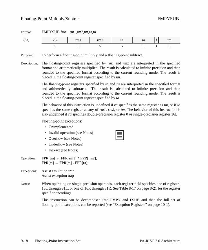
thenult is
tthenult is
et of
Floating-Point Multiply/Subtract FMPYSUB
Format: FMPYSUB,fmt rm1,rm2,tm,ra,ta
(53)
Purpose: To perform a floating-point multiply and a floating-point subtract.
Description: The floating-point registers specified by rm1 and rm2 are interpreted in the specifiedformat and arithmetically multiplied. The result is calculated to infinite precision and rounded to the specified format according to the current rounding mode. The resplaced in the floating-point register specified by tm.
The floating-point registers specified by ta and ra are interpreted in the specified formaand arithmetically subtracted. The result is calculated to infinite precision and rounded to the specified format according to the current rounding mode. The resplaced in the floating-point register specified by ta.
The behavior of this instruction is undefined if ra specifies the same register as tm, or if taspecifies the same register as any of rm1, rm2, or tm. The behavior of this instruction isalso undefined if ra specifies double-precision register 0 or single-precision register 16L.
Floating-point exceptions:
• Unimplemented
• Invalid operation (see Notes)
• Overflow (see Notes)
• Underflow (see Notes)
• Inexact (see Notes)
Operation: FPR[tm] ← FPR[rm1] * FPR[rm2];FPR[ta] ← FPR[ta] - FPR[ra];
Exceptions: Assist emulation trapAssist exception trap
Notes: When operating on single-precision operands, each register field specifies one of registers16L through 31L, or one of 16R through 31R. See Table8-17 on page8-21 for the registerspecifier encodings.
This instruction can be decomposed into FMPY and FSUB and then the full sfloating-point exceptions can be reported (see "Exception Registers" on page 10-1).
26 rm1 rm2 ta ra f tm
6 5 5 5 5 1 5
9-18 Floating-Point Instruction Set PA-RISC 2.0 Architecture

dration
Floating-Point Negate FNEG
Format: FNEG,fmt r,t
(49)
(45)
Purpose: To negate a floating-point value.
Description: The floating-point register specified byr is copied into the floating-point register specifieby t and negated. This operation is non-arithmetic and does not cause an invalid opeexception when a NaN is negated.
Floating-point exceptions:
• Unimplemented
Operation: FPR[t]{all_bits_except_sign}← FPR[r]{all_bits_except_sign};FPR[t]{sign_bit} ← ∼FPR[r]{sign_bit};
Exceptions: Assist emulation trapAssist exception trap
0E r 0 6 0 f 0 0 r t 0 t
6 5 5 3 1 1 2 1 1 1 1 5
0C r 0 6 fmt 0 0 0 t
6 5 5 3 2 2 3 1 5
9-19PA-RISC 2.0 Architecture Floating-Point Instruction Set

de an
Floating-Point Negate Absolute Value FNEGABS
Format: FNEGABS,fmt r,t
(49)
(45)
Purpose: To negate a floating-point absolute value.
Description: The floating-point register specified byr is copied into the floating-point register specifieby t with the sign bit set to 1. This operation is non-arithmetic and does not causinvalid operation exception when the sign of a NaN is set to 1.
Floating-point exceptions:
• Unimplemented
Operation: FPR[t]{all_bits_except_sign}← FPR[r]{all_bits_except_sign};FPR[t]{sign_bit} ← 1;
Exceptions: Assist emulation trapAssist exception trap
0E r 0 7 0 f 0 0 r t 0 t
6 5 5 3 1 1 2 1 1 1 1 5
0C r 0 7 fmt 0 0 0 t
6 5 5 3 2 2 3 1 5
9-20 Floating-Point Instruction Set PA-RISC 2.0 Architecture
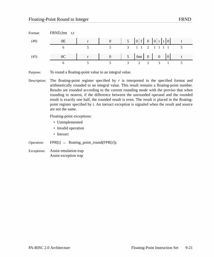
dber.whenundedating-rce
Floating-Point Round to Integer FRND
Format: FRND,fmt r,t
(49)
(45)
Purpose: To round a floating-point value to an integral value.
Description: The floating-point register specified byr is interpreted in the specified format anarithmetically rounded to an integral value. This result remains a floating-point numResults are rounded according to the current rounding mode with the proviso that rounding to nearest, if the difference between the unrounded operand and the roresult is exactly one half, the rounded result is even. The result is placed in the flopoint register specified byt. An inexact exception is signaled when the result and souare not the same.
Floating-point exceptions:
• Unimplemented
• Invalid operation
• Inexact
Operation: FPR[t] ← floating_point_round(FPR[r]);
Exceptions: Assist emulation trapAssist exception trap
0E r 0 5 0 f 0 0 r t 0 t
6 5 5 3 1 1 2 1 1 1 1 5
0C r 0 5 fmt 0 0 0 t
6 5 5 3 2 2 3 1 5
9-21PA-RISC 2.0 Architecture Floating-Point Instruction Set

e andourceoint
Floating-Point Square Root FSQRT
Format: FSQRT,fmt r,t
(49)
(45)
Purpose: To perform a floating-point square root.
Description: The floating-point register specified byr is interpreted in the specified format and thpositive arithmetic square root is taken. The result is calculated to infinite precisionthen rounded to the specified format according to the current rounding mode. If the sregister contains , the result will be . The result is placed in the floating-pregister specified byt.
Floating-point exceptions:
• Unimplemented
• Invalid operation
• Inexact
Operation: FPR[t] ← square_root(FPR[r]);
Exceptions: Assist emulation trapAssist exception trap
0E r 0 4 0 f 0 0 r t 0 t
6 5 5 3 1 1 2 1 1 1 1 5
0C r 0 4 fmt 0 0 0 t
6 5 5 3 2 2 3 1 5
0– 0–
9-22 Floating-Point Instruction Set PA-RISC 2.0 Architecture
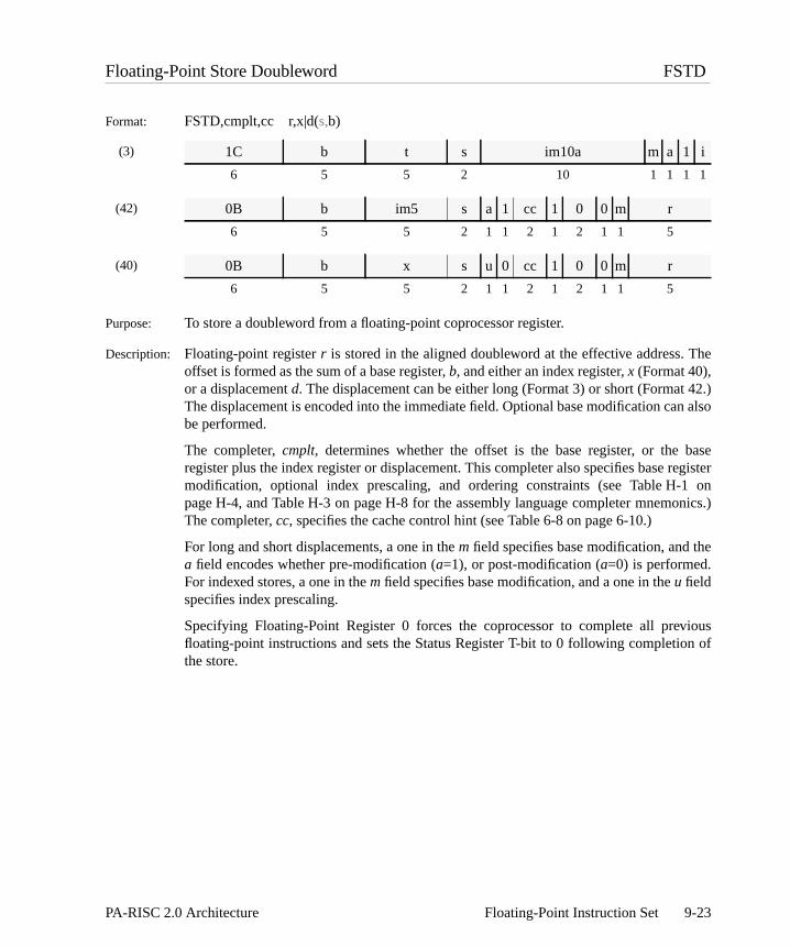
The
42.)n also
baseegister1 onnics.)
e
viousn of
Floating-Point Store Doubleword FSTD
Format: FSTD,cmplt,cc r,x|d(s,b)
(3)
(42)
(40)
Purpose: To store a doubleword from a floating-point coprocessor register.
Description: Floating-point registerr is stored in the aligned doubleword at the effective address. offset is formed as the sum of a base register,b, and either an index register,x (Format 40),or a displacementd. The displacement can be either long (Format 3) or short (FormatThe displacement is encoded into the immediate field. Optional base modification cabe performed.
The completer,cmplt, determines whether the offset is the base register, or the register plus the index register or displacement. This completer also specifies base rmodification, optional index prescaling, and ordering constraints (see Table H-page H-4, and Table H-3 on page H-8 for the assembly language completer mnemoThe completer,cc, specifies the cache control hint (see Table 6-8 on page 6-10.)
For long and short displacements, a one in them field specifies base modification, and tha field encodes whether pre-modification (a=1), or post-modification (a=0) is performed.For indexed stores, a one in them field specifies base modification, and a one in theu fieldspecifies index prescaling.
Specifying Floating-Point Register 0 forces the coprocessor to complete all prefloating-point instructions and sets the Status Register T-bit to 0 following completiothe store.
1C b t s im10a m a 1 i
6 5 5 2 10 1 1 1 1
0B b im5 s a 1 cc 1 0 0 m r
6 5 5 2 1 1 2 1 2 1 1 5
0B b x s u 0 cc 1 0 0 m r
6 5 5 2 1 1 2 1 2 1 1 5
9-23PA-RISC 2.0 Architecture Floating-Point Instruction Set

/) */
les of
Operation: if (indexed_store) /* indexed (Format 40)*/switch (cmplt) {
case S:case SM: dx← lshift(GR[x],3);
break;case M:default: dx← GR[x];
break;}
else if (d > 15 || d < -16) { /* long displacement *dx ← sign_ext(assemble_16a(s,cat(im10a,0),i),16); /* (Format 3cc ← NO_HINT;
} else /* short displacement */dx ← low_sign_ext(im5,5); /* (Format 42) */
space← space_select(s,GR[b],format);if (cmplt == O)
enforce_ordered_store;switch (cmplt) {
case MB: offset← GR[b] + dx;GR[b] ← GR[b] + dx;break;
case MA:case M:case SM: offset← GR[b];
GR[b] ← GR[b] + dx;break;
default: offset← GR[b] + dx;break;
}mem_store(space,offset,0,63,cc,FPR[r]);
Exceptions: Assist exception trap Data memory break trapData TLB miss fault/data page fault TLB dirty bit trapData memory access rights trap Page reference trapData memory protection ID trap Assist emulation trapUnaligned data reference trap
Restrictions: For stores with long displacements (Format 3), only displacements which are multipeight may be used.
If the completerO is specified, the displacement must be 0.
9-24 Floating-Point Instruction Set PA-RISC 2.0 Architecture

et is
rmatn can
baseegister1 onnics.)
nedte all
Floating-Point Store Word FSTW
Format: FSTW,cmplt,cc r,x|d(s,b)
(43)
(44)
(42)
(40)
Purpose: To store a word from a floating-point coprocessor register.
Description: Floating-point registerr is stored in the aligned word at the effective address. The offsformed as the sum of a base register,b, and either an index register,x (Format 40), or adisplacementd. The displacement can be either long (Formats 43 and 44) or short (Fo42.) The displacement is encoded into the immediate field. Optional base modificatioalso be performed.
The completer,cmplt, determines whether the offset is the base register, or the register plus the index register or displacement. This completer also specifies base rmodification, optional index prescaling, and ordering constraints (see Table H-page H-4, and Table H-3 on page H-8 for the assembly language completer mnemoThe completer,cc, specifies the cache control hint (see Table 6-8 on page 6-10.)
For long displacements with base modification, Format 44 is used, and thea field encodeswhether pre-modification (a=1), or post-modification (a=0) is performed. For longdisplacements with no base modification, Format 43 is used.
For short displacements, a one in them field specifies base modification, and thea fieldencodes whether pre-modification (a=1), or post-modification (a=0) is performed. Forindexed stores, a one in them field specifies base modification, and a one in theu fieldspecifies index prescaling.
Specifying floating-point registers 0R, 1L, 1R, 2L, 2R, 3L, or 3R is an undefioperation. Specifying Floating-Point Register 0L forces the coprocessor to compleprevious floating-point instructions.
1F b r s im11a 0 r i
6 5 5 2 11 1 1 1
1E b r s im11a a r i
6 5 5 2 11 1 1 1
09 b im5 s a 1 cc 1 0 r m r
6 5 5 2 1 1 2 1 2 1 1 5
09 b x s u 0 cc 1 0 r m r
6 5 5 2 1 1 2 1 2 1 1 5
9-25PA-RISC 2.0 Architecture Floating-Point Instruction Set

/) */
h are
Operation: if (indexed_store) /* indexed (Format 40)*/switch (cmplt) {
case S:case SM: dx← lshift(GR[x],2);
break;case M:default: dx← GR[x];
break;}
else if (d > 15 || d < -16) { /* long displacement *dx ← sign_ext(assemble_16a(s,im11a,i),16); /* (Formats 43 and 44cc ← NO_HINT;
} else /* short displacement */dx ← low_sign_ext(im5,5); /* (Format 42) */
space← space_select(s,GR[b],format);if (cmplt == O)
enforce_ordered_store;switch (cmplt) {
case MB: offset← GR[b] + dx;GR[b] ← GR[b] + dx;break;
case MA:case M:case SM: offset← GR[b];
GR[b] ← GR[b] + dx;break;
default: offset← GR[b] + dx;break;
}mem_store(space,offset,0,31,cc,FPR[r]);
Exceptions: Assist exception trap Data memory break trapData TLB miss fault/data page fault TLB dirty bit trapData memory access rights trap Page reference trapData memory protection ID trap Assist emulation trapUnaligned data reference trap
Restrictions: For stores with long displacements (Formats 43 and 44), only displacements whicmultiples of four may be used.
If the completerO is specified, the displacement must be 0.
9-26 Floating-Point Instruction Set PA-RISC 2.0 Architecture

tthenult is
Floating-Point Subtract FSUB
Format: FSUB,fmt r1,r2,t
(52)
(48)
Purpose: To perform a floating-point subtraction.
Description: The floating-point registers specified byr1 andr2 are interpreted in the specified formaand arithmetically subtracted. The result is calculated to infinite precision and rounded to the specified format according to the current rounding mode. The resplaced in the floating-point register specified byt.
Floating-point exceptions:
• Unimplemented
• Invalid operation
• Overflow
• Underflow
• Inexact
Operation: FPR[t] ← FPR[r1]− FPR[r2];
Exceptions: Assist emulation trapAssist exception trap
0E r1 r2 1 r2 f 3 0 r1 t 0 t
6 5 5 3 1 1 2 1 1 1 1 5
0C r1 r2 1 fmt 3 0 0 t
6 5 5 3 2 2 3 1 5
9-27PA-RISC 2.0 Architecture Floating-Point Instruction Set

ng
ts.
ointA-bited
in thend is
any ofs notble
ed.
uede
Floating-Point Test FTEST
Format: FTEST cbit /*targeted test*/FTEST,cond /*queue test*/
(47)
Purpose: To test the results of one or more earlier comparisons.
Description: The specified condition in the floating-point Status Register is tested. The condition,cond,is encoded in thec field of the instruction. If the condition is satisfied, then the followiinstruction is nullified.
There are two types of floating-point test instructions – targeted tests and queue tes
• A targeted test tests a specific bit of the compare array (CA) in the floating-pStatus Register (see the second format in Figure 8-6 on page 8-9.) If the Cspecified bycbit is 1, the PSW[N] bit is set to 1. The CA-bit to test is encoded in thyfield of the instruction as xor(cbit+1,1.) No condition may be specified for a targetetest and thec field must be 0.
• A queue test tests for a specific condition in the C-bit and compare queue (CQ) floating-point Status Register (see the first format in Figure 8-6 on page 8-9) aspecified by omitting thecbit operand. A queue test is encoded with ay field of 1.
Floating-point exceptions:
• None
Conditions: For targeted tests, no condition may be specified. For queue tests, the condition is the conditions shown in Table 8-13 on page 8-18. When a condition completer ispecified, the “Simple Test” (C == 1) condition is used. The boolean varia“cond_satisfied” in the operation section is set when the specified condition is satisfi
Operation: if (y == 1) { /*queue test*/if (cond_satisfied)
PSW[N] ← 1;} else { /*targeted test*/
if (FPSR[CA{xor(y,1)–1}]) { /*test CA{cbit}*/PSW[N] ← 1
}
Exceptions: Assist emulation trapAssist exception trap
Restrictions: It is an undefined operation to mix targetedFCMP instructions with queueFTESTinstructions or to mix queueFCMPs with targetedFTESTs. For a targetedFTEST to bedefined, anFCMP to the same CA bit must precede it without any intervening queFCMP. For a queueFTEST to be defined, enough queuedFCMPs must be executed to defin
0C 0 0 y 0 2 0 1 c
6 5 5 3 2 2 3 1 5
9-28 Floating-Point Instruction Set PA-RISC 2.0 Architecture

assists may
the CQ bits being tested without any intervening targetedFCMPs. AnyFTEST may followa load of the FPSR, because the load defines all of the C-, CA-, and CQ-bits.
Notes: This instruction must be implemented, may not be queued and may not cause anyexception traps. However, any assist exception traps caused by previous instructionbe taken while this instruction is in the IA queue.
9-29PA-RISC 2.0 Architecture Floating-Point Instruction Set

itting-
Fixed-point Multiply Unsigned XMPYU
Format: XMPYU r1,r2,t
(52)
Purpose: To perform unsigned fixed-point multiplication.
Description: The floating-point registers specified byr1 and r2 are interpreted as unsigned 32-bintegers and arithmetically multiplied. The unsigned 64-bit result is placed in the floapoint register specified byt.
Floating-point exceptions:
• Unimplemented
Operation: FPR[t] ← FPR[r1] * FPR[r2];
Exceptions: Assist emulation trapAssist exception trap
0E r1 r2 2 r2 0 3 1 r1 0 0 t
6 5 5 3 1 1 2 1 1 1 1 5
9-30 Floating-Point Instruction Set PA-RISC 2.0 Architecture

s
cessor,sor tor may
pter, an
ppingapping whengnal anelayedction is
sabled.
e other Status invalid
cutionvided fortate.
d loadsister as
eptingopcodeom the
thes wouldion. Theented
state
10 Floating-Point Exception
Floating-point instructions may cause an interruption in the processor, an exception in the coproor both. Interruptions are described in Chapter 5, “Interruptions” and always force the procesbranch to a location in the Interruption Vector Table. Floating-point coprocessor exceptions may onot force the processor to trap (that is, force the processor to take an interruption). In this chainstruction which causes a floating-point exception is called an excepting instruction.
Floating-point exceptions are divided into immediate trapping exceptions and delayed traexceptions. Immediate trapping exceptions always force the processor to trap. Delayed trexceptions are further divided into exceptions that always trap, and exceptions that will trap onlythe corresponding trap is enabled. An immediate trapping exception forces the processor to siassist exception trap when the excepting instruction is the current instruction being executed. A dtrapping exception forces the processor to signal an assist exception trap when the current instrua floating-point instruction, and the excepting instruction is a pending instruction.
The only immediate trapping exception is the reserved-op exception. This exception cannot be di
The only delayed trapping exception that cannot be disabled is the unimplemented exception. Thdelayed trapping exceptions are the IEEE exceptions. Each has a corresponding bit in theRegister which enables and disables the delayed trap. The IEEE exceptions are the following:operation, division-by-zero, overflow, underflow, and inexact.
Exception Registers
The exception registers contain information on floating-point operations that have completed exeand have caused a delayed trapping exception. All the registers must be present and storage proloads and stores even if an implementation never uses a particular register to record exception s
The exception registers are accessed with double-word load and store instructions. Single-worand stores of registers 0R, 1L, 1R, 2L, 2R, 3L, and 3R are undefined. Specifying an exception rega source or destination of a non-load/store operation is undefined.
For single-operation instructions, an exception register contains a modified copy of an excinstruction that traps. The coprocessor replaces the field that normally contains the instruction with a code that indicates the type of exception detected. The remaining fields are duplicates froriginal instruction.
The fused-operation instructions (FLOATING-POINT MULTIPLY FUSED ADD and FLOATING-POINTMULTIPLY NEGATE FUSED ADD) cannot directly cause trapping IEEE exceptions, because exception state cannot be represented in the exception registers. When one of these instructioncause a trapping IEEE exception, the implementation causes, instead, an unimplemented exceptfused-operation instruction is placed in an exception register along with the appropriate unimplemexception code.
The multiple-operation instructions (FLOATING-POINT MULTIPLY/ADD and FLOATING-POINTMULTIPLY/SUBTRACT) cannot directly cause trapping IEEE exceptions, because the exception
10-1PA-RISC 2.0 Architecture Floating-Point Exceptions

trapping
in an
case,ppingeeptionally. If
ed andts withe next
d in the
e 10-1.
cannot be represented in the exception registers. When one of these instructions would cause aIEEE exception, the implementation does one of the following:
• Cause, instead, an unimplemented exception. The multiple-operation instruction is placedexception register along with the appropriate unimplemented exception code. Or,
• Treat the multiple-operation instruction as two separate single-operation instructions. In thisan instruction pattern is fabricated for the portion of the instruction that caused the traexception (e.g., the instruction pattern for aFLOATING-POINT ADD if the add operation caused thexception), and this pattern, along with the appropriate exception code, is placed in an excregister. The other operation, if it does not also cause a trapping exception, completes normboth operations cause trapping IEEE exceptions, then two instruction patterns are fabricatplaced in two exception registers. These two instructions have the same ordering constrainrespect to other instructions as for other single-operation instructions as described in thsection.
Figure 10-1 shows the format of the exception registers.The exception and ei fields are explaineparagraphs that follow.
exception The exception code corresponding to the exception detected as shown in TablException codes not listed are reserved.
exception ei
6 26
Figure 10-1. Floating-Point Exception Register Format
10-2 Floating-Point Exceptions PA-RISC 2.0 Architecture

the for a
ld is
ppingdes. Inster and
ception othertions). as the
t must be record
The two bits labeled ‘pp’ in the exception code contain information regarding parameters for the underflow exceptions. See “Underflow Exception” on page 10-12detailed description of this field.
ei All bits other than the major opcode, copied from the excepting instruction. This fieundefined if the exception code is set to ‘no exception’.
Exception Register Operation
When all pending instructions are forced to complete, all operations which complete with a traexception are placed in the exception registers together with their corresponding exception coorder to complete an operation, the coprocessor may place the operation in an exception regimark it with an unimplemented exception.
The coprocessor places the excepting instruction that first entered the IA queues in any of ExRegisters 1 through 7. Other instructions which complete with a trap are placed in any of theavailable Exception Registers (those which are not already occupied by excepting instrucExcepting instructions may be placed in the Exception Registers 1 through 7 in any order as longdata dependencies are preserved (the order need not be the order in which they were fetched buordered for the data dependencies). If an instruction completes without a trapping exception, no
Table 10-1. Floating-Point Exception Codes
Exception code Opcode Description
000000 0C/0E No exception
100000 0C/0E Invalid operation
010000 0C/0E Division-by-zero
001000 0C/0E Overflow
pp0100 0C/0E Underflow
000010 0C/0E Inexact
000001 0C/0E Unimplemented
001010 0C/0E Inexact & Overflow
pp0110 0C/0E Inexact & Underflow
001001 0C Unimplemented
001011 0E Unimplemented
000011 06 Unimplemented
100011 26 Unimplemented
101011 2E Unimplemented
pp1100 2E Underflow
010010 2E Inexact
pp1110 2E Underflow and Inexact
011000 2E Overflow
011010 2E Overflow and Inexact
110000 2E Invalid
10-3PA-RISC 2.0 Architecture Floating-Point Exceptions

setting
ption",
sor, orappingrapping
ps may
is 1, the taken.re the always
moryrapping to the
lem, aerencere the
of that instruction appears in the exception registers. The exception queue need not be packed.
Once software has processed the exception registers, it must clear the exception registers bythem all to zeros before non-load/store instructions can be executed.
If the T-bit equals 0 and any exception register has an exception field not equal to "no exceexecution of any non-load/store floating-point instruction is an undefined operation.
Interruptions and Exceptions
Floating-point instructions may cause interruptions in the processor, exceptions in the coprocesboth. Coprocessor exceptions are divided into immediate trapping exceptions and delayed trexceptions. The only immediate trapping exception is the reserved-op exception. The delayed texceptions consist of the unimplemented exception and the IEEE exceptions.
The IEEE exceptions are the following:
• invalid operation
• division-by-zero
• inexact
• overflow
• underflow
While the unimplemented and reserved-op exceptions must always trap, the IEEE exception trabe disabled.
Each IEEE exception has a corresponding enable bit in the Status Register. When an enable bitcorresponding trap is enabled, and if the corresponding exception occurs, a delayed trap isHowever, on the overflow and underflow exceptions, an implementation may choose to ignoenable bit and always trap on the exception. In such implementations, the corresponding trap isenabled.
Immediate Trapping
Floating-point instructions may cause three types of immediate trapping interruptions: mereference interruptions, the assist emulation trap, and the reserved-op exception. Immediate texceptions and interruptions always cause a trap or fault when the front of the IA queues pointsinterrupting instruction. An interrupting instruction must not alter its operands.
As described in Chapter 4, “Control Flow”, when the processor detects a memory reference probmemory reference fault or trap occurs. Only load and store instructions cause memory refinterruptions. The memory reference interruptions associated with floating-point instructions afollowing:
• Data TLB miss fault/Data page fault
• Data memory access rights trap
• Data memory protection ID trap
10-4 Floating-Point Exceptions PA-RISC 2.0 Architecture

rationister tocessor
ception
not in take a an assistter 0,
take the
ating-
d, and
tore of
nding
pping
or an
apping
• Unaligned data reference trap
• Data memory break trap
• TLB dirty bit trap
• Page reference trap
• Data debug trap
As described in “Coprocessor Configuration Register” on page 6-22, the Coprocessor ConfiguRegister (CCR) in the processor controls the assist emulation trap. Software may set this regforce an assist emulation trap on every occurrence of a floating-point instruction. See “CoproInstructions” on page 6-22 for more information.
Finally, attempting an instruction with a reserved sub-opcode may cause an immediate assist extrap. See “Reserved-op Exception” on page 10-8 for details.
Delayed Trapping
Delayed traps report an exception when the excepting instruction is a pending instruction but isthe IA queues. The following descriptions indicate when the processor and coprocessor maydelayed trap and must take a delayed trap. Normally, a delayed trap forces the processor to takeexception trap. However, if the current instruction is a double-word store of Floating-point Regisall the floating-point registers are set normally as if a trap occurred, but the processor does not assist exception trap.
The coprocessor may signal a delayed trap when at least one of the following occurs:
• A pending instruction caused an unimplemented exception and the current instruction is a flopoint instruction, or
• A pending instruction caused an IEEE exception, the corresponding exception trap is enablethe current instruction is a floating-point instruction.
A delayed trap must occur when at least one of the following conditions exist:
• The T-bit is 1 and the current instruction is any floating-point instruction.
• The exception queue is full and the current instruction is any floating-point instruction.
• A pending instruction causes a trapping exception and the current instruction is a load or sFloating-point Register 0.
• The current instruction is a load or store of an exception register that will be set by a peinstruction.
• The current instruction is a load or store of the destination register of a pending, trainstruction or an operation which depends on a pending, trapping instruction.
• The current instruction is a load of the source register of a pending, trapping instruction operation which depends on a pending, trapping instruction.
• The current instruction is aFLOATING-POINT TEST instruction and the previousFLOATING-POINTCOMPARE either is pending and caused a trapping exception or depends on a pending, tr
10-5PA-RISC 2.0 Architecture Floating-Point Exceptions

ion totruction queues on all
ion” on
nding
ting-ction isit is set
ith an
auses atination
d bias-ng (int,.
ets the
instruction.
An instruction depends on a previous instruction whenever it must wait for the previous instructcomplete in order to ensure that the instructions appear sequentially executed to software. Insdependency is transitive. For example, if the exception queue is full, and every instruction in thedepends on the instruction immediately preceding it, then each instruction in the queue dependthe instructions preceding it.
When a delayed trap occurs, the following happens:
1. The coprocessor completes all pending floating-point instructions.
2. The coprocessor sets the exception registers as described in “Exception Register Operatpage 10-3.
3. The coprocessor sets the Status Register T-bit to 1.
4. For each pending instruction that completes with a trapping IEEE exception, the correspoexception flag may either be set to 1, or left unchanged, but cannot be set to 0.
5. If the current instruction is any floating-point instruction except a double-word store of Floapoint Register 0, the processor takes an assist exception trap. Otherwise, if the current instrua double-word store of Floating-point Register 0, the store completes, no trap occurs, the T-bto 0 and execution proceeds normally.
Any pending instruction which depends on a pending, trapping instruction must complete wunimplemented exception.
Table 10-2 specifies the status of the source and destination registers when an instruction cdelayed trap. When the table indicates the original operand values are preserved, and if the desregister is not one of the source registers, the contents of the destination register are undefined.
As indicated in the table, trapping overflow exceptions and underflow exceptions return a roundeadjusted result. A bias-adjusted result is obtained by dividing (in the case of overflow) or multiplyithe case of underflow) the infinitely precise result by and then rounding. The bias adjustmena, is192 for single-word numbers, 1536 for double-word numbers, and 24576 for quad-word numbers
Non-trapping Exceptions
If an IEEE exception occurs, but the corresponding trap is disabled, then the coprocessor s
Table 10-2. Delayed Trap Results
Exception type Trapped result
Invalid operation original operand values preserved
Division-by-zero original operand values preserved
Overflow rounded bias-adjusted result in destination
Underflow rounded bias-adjusted result in destination
Inexact rounded result in destination
Unimplemented original operand values preserved
2a
10-6 Floating-Point Exceptions PA-RISC 2.0 Architecture

eration
signals aries the
:
may setsets theptions
sets then may
d. The
esult is
nyge
ustn
corresponding flag bit in the Status Register to 1. Table 10-3 lists the results returned by an opwhich completes with a non-trapping exception with a floating point destination format.
Multiple Exceptions
If the current instruction causes a reserved-op exception, and at the same time the coprocessor delayed trap caused by a previous exception, the delayed trap occurs. Software then retinstruction to handle the reserved-op exception.
The only other exceptions which may both occur on the same instruction are one of the following
• inexact and overflow exceptions
• inexact and underflow exceptions
When one of these two cases occur, the action taken is as follows:
1. If both traps are enabled when the coprocessor takes a delayed trap, the implementation either or both corresponding status flags to 1, or leave them unchanged. The coprocessor exception field in the corresponding exception register to the value that indicates both exceoccurred.
2. If only one trap is enabled when the coprocessor takes a delayed trap, the coprocessor corresponding exception field to the value that indicates the enabled trap. The implementatioeither set the flag bit that corresponds to the enabled trap to 1, or leave it unchangecoprocessor sets the flag bit that corresponds to the disabled trap to 1.
3. If neither trap is enabled, the coprocessor sets both corresponding status flags to 1.
If the overflow or underflow exception caused a trap on the instruction, a rounded bias-adjusted rreturned. Otherwise, a rounded result is returned.
Trap Handlers
Programming NoteThe IEEE standard strongly recommends that users be allowed to specify a trap handler for aof the five standard exceptions. The mechanisms to accomplish this are programming languaand operating system dependent.
Since the coprocessor continues to trap if the Status Register T-bit is 1, the trap handler mfirst set the bit to 0 by executing a double-word store of register 0. The trap handler may the
Table 10-3. Non-trapped Exception Results
Exception type Non-trapped result
Invalid operation quiet NaN in destination
Division-by-zero properly signed∞ in destination
Overflow rounded result in destination
Underflow rounded result in destination
Inexact rounded result in destination
10-7PA-RISC 2.0 Architecture Floating-Point Exceptions

tos.
cedasep
thepn.
ither a
. It doesegister.
uson.he
ented-point
on-load/ither an
pt the
ay put
resultverflow
emulate any of the instructions in the exception queue beginning with the instruction inException Register 1 and proceeding sequentially to the end.
The trap handler must clear all the exception registers. If the trap handler chooses not emulate all the instructions, it must reset the T-bit to 1 before returning to the trapped proces
To emulate an instruction, the trap handler computes or specifies a substitute result to be plain the destination register of the operation. The trap handler may determine what operation wbeing performed and what exceptions occurred during the operation by examining thcorresponding exception register. On overflow, underflow, and inexact exceptions, the trahandler has access to the correctly rounded result by examining the destination register of operation. On unimplemented, invalid operation, and divide-by-zero exceptions, the trahandler has access to the operand values by examining the source registers of the instructio
Reserved-op Exception
When a non-load/store instruction has a reserved sub-opcode, an implementation signals ereserved-op exception or an unimplemented exception.
A reserved-op exception always forces the processor to take an immediate assist exception trapnot set the exception registers or the T-bit, and does not change any of the flag bits in the Status RThe reserved-op exception cannot be disabled.
Programming NoteTrapping is immediate for reserved-op exceptions. The trap handler must check for a StatRegister T-bit equal to 0 to determine that the trap was caused by a reserved-op exceptiWhen a reserved-op exception occurs, software interprets the contents of the IIR, nullifies tinstruction pointed to by the front of the IIA queues, and returns control to the trappingprocess.
Unimplemented Exception
If an implementation chooses not to execute an instruction, the instruction signals an unimplemexception. An unimplemented exception always causes a delayed trap on a later floatinginstruction. It does not change the Status Register Flag bits and cannot be disabled. When a nstore floating-point operation references a reserved sub-opcode, an implementation signals eunimplemented exception or a reserved-op exception.
An implementation may signal an unimplemented exception on any floating-point instruction exceFLOATING-POINT TEST instruction, theFLOATING-POINT IDENTIFY instruction, a load instruction, ora store instruction.
When a trap forces the coprocessor to complete all pending instructions, implementations muncompleted instructions in the exception registers and set the correspondingexception field to theappropriate unimplemented exception code.
A conversion to a floating-point format always causes an unimplemented exception when theoverflows, the result lies too far outside the range for the exponent to be bias-adjusted, and the o
10-8 Floating-Point Exceptions PA-RISC 2.0 Architecture

at that trap isented
ler thederflow
integerto an
to beivered,hen theriately
trap is enabled. Table 10-4 shows the result values which produce an unimplemented exception;a is thebias-adjustment value for the destination format,p is the precision, andv is the source value.
Similarly, an unimplemented exception is always caused by a conversion to a floating-point formunderflows, lies too far outside the range for the exponent to be bias-adjusted, and the underflowenabled. Table 10-5 shows the floating-point underflow results which cause an unimplemexception;a is the bias-adjustment value for the destination format,p is the precision, andv is thesource value.
Reporting these overflows and underflows as unimplemented exceptions allows a trap handability to inspect the source operands. Source operands are not preserved on overflow or untrapping exceptions.
Finally, the unimplemented exception is always signaled when the operand of a conversion to anformat is a NaN. Low-level trap handlers may choose to silently deliver a result or convert it invalid exception.
Invalid Operation Exception
An instruction signals the invalid operation exception if an operand is invalid for the operation performed. When the exception occurs without a trap and a floating-point formated result is delthe coprocessor delivers a quiet NaN to the destination register. If an integer result is delivered, tclosest integer is delivered. For example, a signed conversion of an infinity will deliver the appropsigned largest integer. Unsigned conversions will deliver either a zero or the maximum integer.
Table 10-4. Overflow Results Causing Unimplemented Exception
Rounding Mode Ranges
nearest
to 0
to +∞
to
Table 10-5. Underflow Results Causing Unimplemented Exception
Rounding Mode Range
nearest
to 0
to +∞
to
∞– v 2–Emax a+( )
2 2p–
–( )≤< 2Emax a+( )
2 2p–
–( ) v +∞<≤
∞– v 2–Emax a 1+ +( )
≤< 2Emax a 1+ +( )
v +∞<≤
∞– v 2–Emax a 1+ +( )
≤< 2Emax a+( )
2 2p 1–( )–
–( ) v +∞< <
∞– ∞– v 2–Emax a+( )
2 2p 1–( )–
–( )< < 2Emax a 1+ +( )
v +∞<≤
2–Emin a–( )
1 2p 1+( )–
–( ) v 2Emin a–( )
1 2p 1+( )–
–( )< <
2–Emin a–( )
v 2Emin a–( )
< <
2–Emin a–( )
v 2Emin a–( )
1 2p–
–( )≤<
∞– 2–Emin a–( )
1 2p–
–( ) v 2Emin a–( )
<≤
10-9PA-RISC 2.0 Architecture Floating-Point Exceptions

e".
ultsble by
e, an mode
ed
lt
If the exception causes a trap, the coprocessor leaves the operands unchanged.
The invalid operations are:
1. Any arithmetic operation on a signaling NaN except for conversions to integer formats.
2. Magnitude subtraction of infinities like or ;
3. The multiplication of 0 and∞;
4. The division operations and ;
5. Square root if the operand is less than zero;
6. Comparison using conditions involving a "T" or conditions involving "<", ">", "true", or "falswithout a "?", when the operands are unordered. See “Comparison Conditions” on page 8-16
7. Conversion to an integer format of an∞, or when the result overflows. Table 10-6 shows the reswhich produce an integer overflow. In the table, is the most positive integer representathe destination format, is the most negative (zero for unsigned integers), andv is the sourcevalue.
Integer overflow is determined after rounding as if the result has infinite width. For examplunsigned conversion of -0.25 is zero (and inexact) in all rounding modes except . In rounding
, the operation results in an invalid exception.
Division-by-zero Exception
From the standard:
[§]7.2 Division by zero. If the divisor is zero and the dividend is a finite nonzero number, thenthe division by zero exception is signaled. The result, when no trap occurs, is a correctly sign∞ (6.3) [see “Sign Bit” on page 8-24].
When a trap occurs, the operands must be left unchanged.
Inexact Exception
From the standard:
[§]7.5 Inexact. If the rounded result of an operation is not exact or if it overflows without anoverflow trap, then the inexact exception shall be signaled. The rounded or overflowed resu
Table 10-6. Integer Results Causing Invalid Exception
Rounding Mode Ranges
nearest
to 0
to +∞
to
+∞( ) ∞–( )+ +∞( ) +∞( )–
0 0⁄ ∞ ∞⁄
I maxI min
v Imin 1 2⁄–< v Imax 1 2⁄+≥
v Imin 1–≤ v Imax 1+≥
v Imin 1–≤ v Imax>
∞– v Imin< v Imax 1+≥
∞–∞–
10-10 Floating-Point Exceptions PA-RISC 2.0 Architecture

e
ct.
had the. On all of thisrations, trap is
.
is the
rmat,10-8.
ign.
rries
and
er to the
rflows
shall be delivered to the destination or, if an inexact trap occurs, to the trap handler [thdestination register in this architecture].
A conversion to a fixed-point format also signals the inexact exception when the result is not exa
Overflow Exception
To determine overflow on an operation, the coprocessor uses the result that would have occurredresult been computed and rounded as if the destination’s exponent range were unboundedoperations except converts, the coprocessor signals an overflow exception when the magnituderesult exceeds the destination format’s largest finite number. The same is true of conversion opeexcept that when this result is beyond the range of bias-adjusted numbers and the overflowenabled, the instruction causes an unimplemented exception.
An instruction cannot cause an overflow exception when at least one operand is a NaN or infinity
Table 10-7 summarizes the result values that cause an overflow exception. In the table,maximum exponent value for the destination format,p is the precision of the format, andv is the valueof the exact result before rounding.
* When the overflow trap is enabled and the operation is a conversion to a floating-point fothis bound is limited to bias-adjusted numbers. See “Unimplemented Exception” on page
When no trap occurs, the result of an overflow exception is one of the following:
1. Round to nearest carries all overflows to∞ with no change in sign.
2. Round toward 0 carries all overflows to the format’s largest finite number with no change in s
3. Round toward−∞ carries positive overflows to the format’s largest finite number, and canegative overflows to−∞.
4. Round toward +∞ carries negative overflows to the format’s most negative finite number, carries positive overflows to +∞.
When an overflow exception causes a trap, the excepting operation returns a bias-adjusted numbdestination register.
The overflow exception is not signaled for integer results. The coprocessor signals integer ovewith an unimplemented exception.
Table 10-7. Results Causing Overflow Exception
Rounding Mode Ranges
nearest
to 0
to +∞
to
Emax
2Emax 2 2
p––( ) v +∞*<≤ ∞–
*v 2
Emax 2 2p–
–( )–≤<
2Emax 1+( )
v +∞*<≤ ∞–*
v 2Emax 1+( )
–≤<
2Emax 2 2
p 1–( )––( ) v +∞*< < ∞–
*v 2
Emax 1+( )–≤<
∞– 2Emax 1+( )
v +∞*<≤ ∞–*
v 2Emax 2 2
p 1–( )––( )–< <
10-11PA-RISC 2.0 Architecture Floating-Point Exceptions

y
tere
undedding toon even
is
ed after and
occurs.tininess
alized
tination resultption is
perandand.
leftmost
Underflow Exception
From the standard:
[§]7.4 Underflow. Two correlated events contribute to underflow. One is the creation of a tin
nonzero result between which, because it is tiny, may cause some other exception lasuch as overflow upon division. The other is extraordinary loss of accuracy during thapproximation of such tiny numbers by denormalized numbers.
Tininess is detected on a nonzero result which lies strictly between , when the result is roas if the exponent range were unbounded. Note that rounding for detection of tininess and roundetermine a result are distinct. In certain cases, the coprocessor signals an underflow exceptithough it returns a normalized result to the destination register.
Table 10-8 shows the range of exact results which will cause detection of tininess. In the table,the minimum exponent value for the destination format,p is the precision of the format, andv is thevalue of the exact result before rounding.
Loss of accuracy occurs when the coprocessor detects an inexact result, where the result returnrounding differs from what the result would have been if the destination had infinite precisionunbounded range.
An instruction causes an underflow exception when the underflow trap is enabled and tininess An instruction also causes an underflow exception when the underflow trap is disabled and both and loss of accuracy occur.
An operation which causes a non-trapping underflow exception may return a zero, denorm
number, or .
Trapped underflows on all operations except conversions deliver a bias-adjusted result to the desregister. Trapped underflow on conversions to a floating-point format delivers a bias-adjustedwhen the result can be represented by a bias-adjusted number. If not, an unimplemented excesignaled instead of an underflow exception.
Conversion to an integer format cannot underflow. The result when the magnitude of the source ois less than 1 is either 0, +1, or−1 depending on the rounding mode and the sign of the source oper
When an instruction causes a trapping underflow exception and the trap enable bit equals 0, the
Table 10-8. Results Causing Tininess
Rounding Mode Range
nearest
to 0
to +∞
to
2Emin±
2Emin±
Emin
2Emin 1 2
p 1+( )––( )– v 2
Emin 1 2p 1+( )–
–( )< <
2Emin– v 2
Emin< <
2Emin– v 2
Emin 1 2p–
–( )≤<
∞– 2Emin 1 2
p––( )– v 2
Emin<≤
2Emin±
10-12 Floating-Point Exceptions PA-RISC 2.0 Architecture

stro. Thenitely caused
ores oft a laterating-
vious-bit to 0. Statusre letse the IIA
ouble-entireegister-word
two bits in the corresponding exception register’sexception field are set (see Figure 10-2). The firparameter bit, the round away (RA) bit, is set to 1 whenever the result is rounded away from zesecond is the inexact (I) bit which is set to 1 if the rounded bias-adjusted result is not the infiprecise result. The trap handler uses this information to denormalize the result and prevent errorsby rounding twice.
Saving and Restoring State
To save state, software first performs a double-word store of register 0, then double-word stregisters 1, 2, and 3, and a sufficient number of double-word stores to save registers needed atime. Thirty-two double-word coprocessor stores are sufficient to save the entire state of the flopoint coprocessor.
A double-word store of register 0 cancels all pending traps, forces the completion of all preinstructions, suppresses any ensuing trap, completes the store, and sets the Status Register TWhen the store cancels a trap, the value written to memory has the bit corresponding to theRegister T-bit set to 1; otherwise, this bit is set to 0. This special treatment of a double-word stothe save routine be nested, does not require the assistance of a trap handler, and need not havqueues enabled.
To restore state, software performs double-word loads of all required registers, followed by a dword load of Floating-point Register 0. Thirty-two double-word loads are sufficient to restore the state of the coprocessor. A double-word load of Floating-point Register 0 which sets the Status RT-bit to 1 re-arms a trap. The next floating-point instruction will cause a trap (apart from a doublestore of Floating-point Register 0).
The following sequences save and restore the entire state of the coprocessor.
RA I 0 1 0/1 0
1 1 1 1 1 1
Figure 10-2. Exception Field Underflow Parameters
; enter with SaveAreaPtr pointing at the first double-word of the save areaInstruction Comment
SAVEFPUFSTD,MA FPR0,8(SaveAreaPtr) ;quiescent, cancel trapFSTD,MA FPR1,8(SaveAreaPtr) ;save exception registerFSTD,MA FPR2,8(SaveAreaPtr) ;save exception registerFSTD,MA FPR3,8(SaveAreaPtr) ;save exception registerFSTD,MA FPR4,8(SaveAreaPtr) ;save data registerFSTD,MA FPR5,8(SaveAreaPtr) ;save data register
•••
FSTD,MA FPR30,8(SaveAreaPtr) ;save data registerFSTD FPR31,0(SaveAreaPtr) ;save last data register
10-13PA-RISC 2.0 Architecture Floating-Point Exceptions

first and
The only required ordering in these sequences is that Floating-point Register 0 must be saved restored last.; enter with SaveAreaPtr pointing at the last double-word of the save area.RSTFPU Instruction Comment
FLDD 0(SaveAreaPtr),FPR31 ;restore data registerFLDD,MB -8(SaveAreaPtr),FPR30 ;restore data register
•••
FLDD,MB -8(SaveAreaPtr),FPR4 ;restore data registerFLDD,MB -8(SaveAreaPtr),FPR3 ;restore exception registerFLDD,MB -8(SaveAreaPtr),FPR2 ;restore exception registerFLDD,MB -8(SaveAreaPtr),FPR1 ;restore exception registerFLDD,MB -8(SaveAreaPtr),FPR0 ;restore exception register
;potentially re-arm trap
10-14 Floating-Point Exceptions PA-RISC 2.0 Architecture

or
whichonitor
tures.
s, their
cessor if the
nitoror. Theapter 5,
entation
11 Performance Monitor Coprocess
The performance monitor coprocessor is an optional, implementation-dependent coprocessorprovides a minimal common software interface to implementation-dependent performance mhardware.
The performance monitor coprocessor responds to coprocessor instructions with auid equal to 2.
Performance Monitor Instructions
The performance monitor instruction set consists of two instructions,PERFORMANCE MONITORENABLE (PMENB) and PERFORMANCE MONITOR DISABLE (PMDIS), which provide a commonsoftware interface to enable and disable the implementation-dependent performance monitor fea
The following figure shows the format of these operations and Table 11-1 shows the operationmnemonics, and sub-opcodes:
The performance monitor coprocessor instructions are described at the end of this chapter.
When a performance monitor coprocessor instruction is executed and CCR{2} is 0, the coproinstruction causes an assist emulation trap. It is an undefined operation to set CCR{2} to 1performance monitor coprocessor is nonexistent.
Performance Monitor Interruptions
Interruption vector number 29 in interruption group 2 is defined as the performance mocoprocessor interrupt for implementation-dependent use by the performance monitor coprocessinterrupt is unmasked when the PSW F-bit is 1, and is masked when the PSW F-bit is 0. See Ch“Interruptions” for additional details.
Reserved Sub-Opcode Exception
When a performance monitor coprocessor instruction has a reserved sub-opcode, the implemmust signal a reserved-op exception by taking an assist exception trap.
0C rv sub 2 n rv
6 12 5 3 1 5
Table 11-1. Performance Monitor Operations
Opcode Sub-op Mnemonic Operation
0C 1 PMDIS Disable performance monitor0C 3 PMENB Enable performance monitor0C 0,2,4..F undefined0C 10..1F reserved
11-1PA-RISC 2.0 Architecture Performance Monitor Coprocessor

mancedent.
erflowset by
ers
Monitor Units
The monitor units are hardware units used to collect the necessary information during performonitoring. The number of the monitor units and their hardware types are implementation depen
If a monitor unit provides counters, the most significant bit of the counter is required to be an ovindicator. The bit must be set when the counter overflows and must remain set until explicitly resoftware. When the overflow indicator is set the remaining bits of the counter are undefined.
NOTEIf counters are used to implement the measurement units, it is recommended that the countbe at least 32 bits wide.
11-2 Performance Monitor Coprocessor PA-RISC 2.0 Architecture

and
n ister is
Performance Monitor Disable PMDIS
Format: PMDIS,n
(55)
Purpose: To disable the implementation-dependent performance monitor coprocessor,conditionally nullify the following instruction.
Description: Disable all measurement units, after the current instruction. The following instructionullified if measurement is enabled and the ,N completer is specified. The compleencoded in then field of the instruction.
Operation: if (n && measurement_enabled)PSW[N] ← 1;
measurement_enabled← 0;
Exceptions: Assist emulation trap
0C rv 1 2 n rv
6 12 5 3 1 5
11-3PA-RISC 2.0 Architecture Performance Monitor Coprocessor

Performance Monitor Enable PMENB
Format: PMENB
(55)
Purpose: To enable the implementation-dependent performance monitor coprocessor.
Description: Enable the measurement units, starting with the next instruction.
Operation: measurement_enabled← 1;
Exceptions: Assist emulation trap
0C rv 3 2 0 rv
6 12 5 3 1 5
11-4 Performance Monitor Coprocessor PA-RISC 2.0 Architecture

levelsed to) paged (2) the PID
virtuale low-ntifiers;ich are
ta or
resses
sical TLB
ntationall the
puts,
A Glossary
Absolute Address
See Physical Address.
Access Rights
A function of virtual address translation that controls access to each page through privilegefor read, write, execute, and gateway. The TLB contains, within each entry, information usdetermine who may have access to that page. This information is divided into two groups: (1access (access ID) which is used to determine if a process or user may access a page; anaccess rights field that is combined with the user’s privilege level and the WD bit of theregister to determine if the type of access the user is requesting will be allowed.
Address
PA-RISC is a byte-addressable system which uses both virtual and absolute addresses. Aaddress can be split into two parts: the high-order bits which are the space identifier and thorder bits that give the offset within the space. Absolute addresses do not have space ideonly a 64-bit offset. Doublewords, words, and halfwords are always located at addresses whaligned to their size (in bytes). Quadwords are aligned on doubleword boundaries.
Address Translation
For a virtual memory system, the process whereby the virtual (logical) address of dainstructions is translated to its absolute address in physical memory.
Aliasing
The condition when the same physical memory location is accessed by different virtual addor by both an absolute and a virtual address.
Alter
The action of setting the E-bit of a TLB entry to 0 and modifying some portion of the phypage number field. Altered entries in the TLB are still visible to software through the insertprotection instructions.
Architecture
Refers to the time-independent functional appearance of a computer system. An implemeof an architecture is an ensemble of hardware, firmware, and software that provides functions as defined in the architecture.
Arithmetic and Logical Unit (ALU)
The part of a PA-RISC processor that performs arithmetic and logic operations on its inproducing output and status information.
A-1PA-RISC 2.0 Architecture Glossary

nce orlizedemory
resses.
is called
.
ge.
m.
s is to
ted to makes
etrievedeparate
Assist Processor
A processor which may be added to the basic PA-RISC system to enhance performafunctionality for algorithms which experience substantial gains from the use of speciahardware. Assist processors are differentiated by the level at which they interface with the mhierarchy. (See special function units and coprocessors).
B-bit (Taken Branch in Previous Cycle)
A bit in the PSW that is 1 if the previous instruction was a taken branch.
Base Register
A register that holds the numeric value that is used as a base value in the calculation of addDisplacements or index values are added to this base value.
Base-Relative Branch
When a general register is used as the base offset to obtain the target address, the branchbase relative.
Biased Exponent
The exponent field for a floating-point number. It consists of the true exponent plus the bias
Binary Floating-point Number
A number format consisting of the three components: sign, exponent, and significand.
Block TLB
A block TLB provides fixed address translations which map address ranges larger than a pa
Byte
A group of eight contiguous bits which is the smallest addressable unit on a PA-RISC syste
C-bit (Code Address Translation Enable)
A bit in the PSW that specifies whether virtual address translation of the instruction addresbe performed.
Cache
A high-speed buffer unit between main memory and the CPU. The cache is continually updacontain recently accessed contents of main memory to reduce access time. When a programa memory request, the CPU first checks to see if the data is in the cache so that it can be rwithout accessing memory. There may be one cache for both instructions and data or scaches for each.
A-2 Glossary PA-RISC 2.0 Architecture

ages.age of
n howsystem
ested by
ding
hecks
data
e. PA-ation
dressermine
Cache Coherence
The property of multiple caches whereby they provide identical shared memory imProcessors in a multiprocessor system are said to be cache coherent if they provide the imsingle cache.
Cache Control Hint
A 2-bit field in some memory reference instructions which provides a hint to the processor oto resolve cache coherence. The processor may disregard the hint without compromising integrity, but performance may be enhanced by following the hint.
Cache Miss
A cache miss occurs when the cache does not contain a copy of the cache line being requthe address. The cache is updated with data and re-accessed.
Carry/Borrow Bits
A 16-bit field in the PSW that indicates if a carry or borrow occurred from the corresponnibble (4 bits) as a result of the previous arithmetic operation.
Central Processing Unit (CPU)
The part of a PA-RISC processor that fetches and executes instructions.
Check
The interruption condition when the processor detects an internal or external malfunction. Cmay be either synchronous or asynchronous with respect to the instruction stream.
Coherence Check
An action taken by hardware to insure coherence.
Combined TLB
Some systems have a TLB which provides address translation for both instruction andreferences.
Compatibility
The ability for software developed for one machine type to execute on another machine typRISC provides compatible execution of application programs written for earlier-generHewlett-Packard computer systems.
Completer
A machine instruction field used to specify instruction options. Typical options include admodification, address indexing, precision of operands, and conditions to be tested to detwhether to nullify the following instruction.
A-3PA-RISC 2.0 Architecture Glossary

ction is
ction,ontrol
cache.cializedlly have
ssors.a bit inal. If a
mpt to
Q and
to be
ed fromhe) and
rs arelied
Condition
The state of a value or a relationship between values used in determining whether an instruto branch, nullify, or trap.
Control Register (CR)
A register which contains system state information used for memory access proteinterruption control, and processor state control. A PA-RISC processor contains 25 cregisters (7 more are reserved).
Coprocessor
A type of assist processor which interfaces to the memory hierarchy at the level of the Coprocessors are special purpose units that work with the main processor to speed up speoperations such as floating-point arithmetic and graphics processing. Coprocessors generatheir own internal state and hardware evaluation mechanism.
Coprocessor Configuration Register (CCR)
The CCR (in CR 10) is an 8-bit register which records the presence and usability of coproceEach bit position (0-7) corresponds to the coprocessor with the same unit number. Setting the CCR to 1 enables the use of the corresponding coprocessor, if present and operationCCR bit is 0, the corresponding coprocessor, if present, is logically decoupled and an attereference the coprocessor causes an assist emulation trap.
Current Instruction
The instruction whose address is in the front element of the instruction address queues (IASIAOQ).
D-bit (Data Address Translation Enable)
A bit in the PSW that specifies whether virtual address translation of data addresses isperformed.
Data Cache (D-cache)
A high-speed storage device which contains data items that have been recently accessmain memory. The D-cache can be accessed independently of the instruction cache (I-cacno synchronization is performed.
Data TLB (DTLB)
A separate TLB which does address translation only for data memory references.
Denormalized Numbers
Any non-zero floating-point number with the exponent field all zeros. Denormalized numbedistinguished from normal numbers in that the value of the “hidden” bit to the left of the impbinary point is zero.
A-4 Glossary PA-RISC 2.0 Architecture

to as
abled
tion.
tained
endian
dress
he twobits ins: Space
two
n. The
Dirty
A block of memory (commonly a cache line or a page) which has been written to is referreddirty.
Disabling an Interrupt
A disabled interrupt is prevented from occurring. The interruption does not wait until re-enand it is not kept pending.
Displacement
The amount that is added to a base register to form an offset in the virtual address computa
Dynamic Displacement
If the displacement value is computed during the course of program execution and is obfrom a general register, it is called dynamic.
E-bit (Little Endian Memory Access Enable)
A bit in the PSW which determines whether memory references assume big endian or little byte ordering.
Effective Address
The address of the operand for the current instruction, derived by applying specific adbuilding rules.
Equivalently Aliased
A condition when two virtual addresses map to the same physical address, and where taddresses are identical in the following bits: Offset bits 12 through 31. If the use of space generating the cache index is enabled, the addresses must also be identical in these bitIdentifier bits 36 through 39, 44 through 47, and 52 through 63.
Equivalently Mapped
A condition when a virtual address is equal to its absolute address.
Exponent
The part of a binary floating-point number that normally signifies the integer power to whichis raised in determining the value of the represented number.
External Branch Instructions
The target of these instructions may lie in a different address space than that of the instructioexternal branch instructions are:BE andBLE.
A-5PA-RISC 2.0 Architecture Glossary

hening to
Whenupt.
annotfter the
onous
ating-m andoating-lso be
SQ and not
st ofally
highestd hold
External Interrupt Enable Mask (EIEM)
The EIEM (CR 15) is a 64-bit register containing one bit for each external interrupt class. Wset to 0, bits in the EIEM mask interruptions pending for the external interrupts correspondthose bit positions.
External Interrupt Request Register (EIR)
The EIR register (CR 23) is a 64-bit register containing one bit for each external interrupt. set to 1, a bit designates that an interruption is pending for the corresponding external interr
F-bit (Performance Monitor Interruption Unmask)
A bit in the PSW used to unmask the performance monitor interruption.
Fault
The interruption condition when the current instruction requests a legitimate action which cbe carried out due to a system problem such as the absence of a main memory page. Asystem problem is cleared, the faulting instruction will execute normally. Faults are synchrwith respect to the instruction stream.
Floating-point Register (FPR)
A storage unit which constitutes the basic resource of the floating-point coprocessor. Flopoint registers are at the highest level of memory hierarchy and are used to load data frostore data to memory and hold operands and results of the floating-point coprocessor. The flpoint coprocessor contains 32 double-precision (64-bit) floating-point registers which may aaccessed as 64 single-precision (32-bit), or 16 quad-precision (128-bit) registers.
Following Instruction
The instruction whose address is in the back element of the instruction address queues (IAIAOQ). This instruction will be executed after the current instruction. This instruction isnecessarily the next instruction in the linear code space.
Fraction
The portion of the significand explicitly contained in a binary floating-point number. The rethe significand is the “hidden” bit to the left of the implied binary point. The “hidden” bit normhas the value one.
G-bit (Debug Trap Enable)
A bit in the PSW used to enable data and instruction debug traps.
General Register (GR)
A storage unit which constitutes the basic resource of the CPU. General registers are at thelevel of memory hierarchy and are used to load data from and store data to memory anoperands and results from the ALU. A PA-RISC processor contains 32 general registers.
A-6 Glossary PA-RISC 2.0 Architecture

at a
ediate
iority
t (IA The
in the
space. The
for use
ace for
ction.
m mainand no
H-bit (Higher Privilege Transfer Trap Enable)
A bit in the PSW that enables an interruption whenever the following instruction will executehigher privilege level.
High-Priority Machine Check (HPMC)
An interruption which occurs when a hardware error has been detected which requires immattention.
I-bit (External, Power Failure, and LPMC Interruption Unmask)
A bit in the PSW used to unmask external interrupts, power failure interrupts, and low-prmachine check interruptions.
IAOQ (Instruction Address Offset Queue)
A two-element queue of 64-bit registers that is used to hold the Instruction Address offseoffset). The first element is IAOQ_Front and holds the IA offset of the current instruction.other element is IAOQ_Back and holds the IA offset of the following instruction.
IA-Relative Branches
When a displacement is added to the current Instruction Address offset (IA offset) to obtatarget address, the branch is called IA relative.
IASQ (Instruction Address Space Queue)
A two-element queue of up to 64-bit registers that is used to hold the Instruction Address(IA space). The first element is IASQ_Front and holds the IA space of the current instructionother element is IASQ_Back and holds the IA space of the following instruction.
IIAOQ (Interruption Instruction Address Offset Queue)
A two-element queue of 64-bit registers that is used to save the Instruction Address offset in processing interruptions.
IIASQ (Interruption Instruction Address Space Queue)
A two-element queue of up to 64-bit registers that is used to save the Instruction Address spuse in processing interruptions.
Infinity
The binary floating-point numbers that have all ones in the exponent and all zeros in the fraThe values of these two numbers are distinguished only by the sign. Thus, they are +∞ and− ∞.
Instruction Cache (I-cache)
A high-speed storage device that contains instructions that have been recently accessed fromemory. The I-cache can be accessed independently of the data cache (D-cache) synchronization is performed.
A-7PA-RISC 2.0 Architecture Glossary

pply)
traps,
or the
of anpe of
20),meters to anen theved in
out ofint of
of anpe of
ned to
Instruction TLB (ITLB)
A separate TLB which does address translation only for instructions.
Interrupt
The interruption condition when an external entity (such as an I/O device or the power surequires attention. Interrupts are asynchronous with respect to the instruction stream.
Interruption
An event that changes the instruction stream to handle exceptional conditions includingchecks, faults, and interrupts.
Interruption Instruction Register (IIR)
The IIR (CR 19) is used by the hardware to store the instruction that caused the interruptioninstruction that was in progress at the time the interruption occurred.
Interruption Offset Register (IOR)
The IOR (CR 21) receives a copy of the offset portion of a virtual address at the time interruption whenever the PSW Q-bit is 1. The value copied is dependent upon the tyinterruption.
Interruption Parameter Registers (IPRs)
The Interruption Instruction Register or IIR (CR 19), Interruption Space Register or ISR (CRand Interruption Offset Register or IOR (CR 21) are collectively termed the Interruption ParaRegisters or IPRs. They are used to pass the interrupted instruction and a virtual addresinterruption handler. These registers are set (or frozen) at the time of an interruption whPSW Q-bit is 1. The IPRs can be read reliably only when the PSW Q-bit is 0. The values sathese registers are dependent upon the type of interruption.
Interruption Processor Status Word (IPSW)
The IPSW (CR 22) receives the value of the PSW when an interruption occurs. The layIPSW is identical to that of PSW and it always reflects the machine state at the pointerruption.
Interruption Space Register (ISR)
The ISR (CR 20) receives a copy of the space portion of a virtual address at the timeinterruption whenever the PSW Q-bit is 1. The value copied is dependent upon the tyinterruption.
Interruption Vector Address (IVA)
The IVA (CR 14) contains the absolute address of an array of service procedures assiginterruptions.
A-8 Glossary PA-RISC 2.0 Architecture

ion, it is
ion, it is
mer is
ysicalough
at a
on.
efored, and read range
rupt is
Interspace Branches
When the target of the branch lies in a different address space as that of the branch instructreferred to as an interspace branch.
Intraspace Branches
When the target of the branch lies in the same address space as that of the branch instructreferred to as an intraspace branch.
Interval Timer
Two internal registers which are both accessed through Control Register 16. The Interval Tia free-running counter that signals an interruption when equal to a comparison value.
Invalidate
The action of setting the E-bit of a TLB entry to a 0, leaving the virtual page number and phpage number fields unchanged. Invalid entries in the TLB are still visible to software thrinsert TLB protection instructions.
L-bit (Lower Privilege Transfer Trap Enable)
A bit in the PSW that enables an interruption whenever the following instruction will executelower privilege level.
Local Branch Instructions
The target of these instructions always lie in the same address space as that of the instructi
Low-Priority Machine Check (LPMC)
An interruption which occurs when a recoverable hardware error has been detected.
M-bit (High-Priority Machine Check Mask)
A bit in the PSW that disables the recognition of an HPMC.
Many-Reader/One-Writer Non-Equivalent Aliasing
A condition where multiple virtual addresses are non-equivalent aliases. Generally, benabling a write-capable translation, any non-equivalent read-only aliases must be disablethe affected address range flushed from the cache. Similarly, before re-enabling thetranslation(s), the write-capable translation must be disabled, and the affected addressflushed from the cache.
Masking an Interrupt
A masked interrupt can still be recognized as a pending event but occurrence of the interdelayed until it is unmasked.
A-9PA-RISC 2.0 Architecture Glossary

to
0000000
sical
. NaN. Thet bit in
eet the
has, and Z
, the
alled
Memory
A device capable of storing information in binary form. The term “memory” typically refersmain memory.
Memory Address Space
The memory address space consists of absolute addresses in the range 0x000000000through 0xEFFFFFFFFFFFFFFF.
Memory-mapped I/O
Control of input and output through load and store instructions to particular virtual or phyaddresses.
Move-in
The action of bringing data or instructions into a cache.
Multiprocessor
A computer with multiple processors.
NaN
The binary floating-point numbers that have all ones in the exponent and a non-zero fractionis the term used for a binary floating-point number that has no value (i.e., “Not a Number”)two types of NaNs, quiet and signaling, are distinguished by the value of the most significanthe fraction field. A zero indicates a quiet NaN and a one indicates a signaling NaN.
Non-Equivalently Aliased
A condition when two virtual addresses map to the same physical address, but do not mrequirements for equivalently aliased addresses. (See “Equivalently Aliased” on page A-5.)
Nullify
To nullify an instruction is equivalent to skipping over that instruction. A nullified instruction no effect on the machine state (except that the IA queues advance and the PSW B, N, X, Ybits are set to 0). The current instruction is nullified when the PSW N-bit is 1.
P-bit (Protection Identifier Validation Enable)
A bit in the PSW that is used as a protection identifier validation enable bit. If the P-bit is 1Protection Identifiers in control registers 8, 9, 12, and 13 are used to enforce protection.
Page
Virtual memory is partitioned into pages which can be resident in matching size blocks (cpage frames) in memory. The smallest page size is 4096 bytes (4 Kbytes).
Page Group
Eight contiguous pages, with the first of these pages beginning on a 32-Kbyte boundary.
A-10 Glossary PA-RISC 2.0 Architecture

nslated.hysical
0 to 3,nt of
tant of
overy
re each
ction
for
ting at
pecialmber.ational.pt to
Physical Address
The address that is the result of the virtual address translation or any address that is not traA physical address is the concatenation of the physical page number and the offset. Paddresses are also referred to as absolute addresses.
Privilege Level
The PA-RISC access control mechanisms are based on 4 privilege levels numbered fromwith 0 being the most privileged. The current privilege level is maintained in the front elemethe Instruction Address Offset Queue (IAOQ_Front).
Processor Status Word (PSW)
A 64-bit register which contains information about the processor state.
Q-bit (Interruption State Collection Enable)
A bit in the PSW that, when set to 1, enables collection of the machine state at the insinterruption (IIASQ, IIAOQ, IIR, ISR, and IOR).
R-bit (Recovery Counter Enable)
A bit in the PSW that enables recovery counter trapping and decrementing of the RecCounter.
Read-Only Non-Equivalent Aliasing
A condition where multiple virtual addresses map to the same physical address, and whevirtual address has a read-only translation.
Recovery Counter
The Recovery Counter (CR 0) counts down by 1 during execution of each non-nullified instrufor which the PSW R-bit is 1.
Remove
The action of taking a TLB entry out of the TLB. Insertion of translations into the TLB, example, causes other entries to be removed.
S-bit (Secure Interval Timer)
A bit in the PSW that, when set to 1, allows the Interval Timer to be read only by code executhe most privileged level.
SFU Configuration Register (SCR)
The SCR (in CR 10) is an 8-bit register which records the presence and usability of SFUs (SFunction Units), Each bit position (0-7) corresponds to the SFU with the same unit nuSetting a bit in the SCR to 1 enables the use of the corresponding SFU if present and operIf a SCR bit is 0, the corresponding SFU if present, is logically decoupled and an attemreference the SFU causes an assist emulation trap.
A-11PA-RISC 2.0 Architecture Glossary

-RISC24, and
ns. Itted or
en”)
tual
essor
evel. It
e done in given
done in
f theseystem
Shadow Register (SHR)
A register into which the contents of a general register are copied upon interruptions. A PAprocessor contains 7 shadow registers which receive the contents of GRs 1, 8, 9, 16, 17, 25. The contents of the shadow registers are copied back to these GRs by theRETURN FROMINTERRUPTION AND RESTORE instruction.
Shift Amount Register (SAR)
The SAR (CR 11) is used by the variable shift, extract, deposit, and branch on bit instructiospecifies the number of bits or the ending bit position of a quantity that is to be shifted, extracdeposited.
Sign
A one bit field in which one indicates a negative value and zero indicates a positive value.
Significand
The component of a binary floating-point number that consists of the implicit (or “hiddleading bit to the left of the implied binary point together with the fraction field to its right.
Space Identifier (Space ID)
An up to 64-bit value which combines with the offset to form the upper portion of a viraddress.
Space Register (SR)
A register used to specify the space identifier for virtual addressing. A PA-RISC proccontains 8 space registers.
Special Function Unit (SFU)
A type of assist processor which interfaces to the memory hierarchy at the general register lacts as an alternate ALU for the main processor and may have its own internal state.
Static Displacement
If the displacement is a fixed value that is known at compile time, it is called static.
Strong Ordering
The property that accesses to storage, such as loads and stores, appear to software to bprogram order. In multiprocessing systems, strong ordering means that accesses by aprocessor appear to that processor as well as to all other processors in the system, to beprogram order.
System Mask
The W, E, O, G, F, R, Q, P, D, and I bits of the PSW are known as the system mask. Each obits, with the exception of the Q-bit, may be set to 1, set to 0, written, and read by the scontrol instructions that manipulate the system mask.
A-12 Glossary PA-RISC 2.0 Architecture

itional
LB.ores) or
g the
n this
hen ahe TLBts, them the
annotfter the
mory.absolute
e use
T-bit (Taken Branch Trap Enable)
A bit in the PSW that enables the taken branch trap.
Taken Branch
Conditional branches are considered to be “taken” if the specified condition is met. Uncondbranches are always “taken”.
TLB Entry
A virtual to physical address translation, either valid or invalid, which is present in the TEntries are visible to software through either references (such as loads, stores, and semaphinsert TLB protection instructions (IITLBP andIDTLBP).
TLB Miss Handling
The action taken, either by hardware or software, on a TLB miss. This involves insertinmissing translation into the proper TLB.
TLB Miss
The condition when there is no entry in the TLB matching the current virtual page number. Icase, the TLB is updated either by software or by hardware.
TLB Slot
A hardware resource in the TLB which holds a TLB entry.
Translation Lookaside Buffer (TLB)
A hardware unit which serves as a cache for virtual-to-absolute memory address mapping. Wmemory reference is made to a given virtual address, the virtual page number is passed to tand the TLB is searched for an entry matching the virtual page number. If the entry exisabsolute page number (contained in the entry) is concatenated with the page offset frooriginal virtual address to form an absolute address.
Trap
The interruption condition when either (1) the function requested by the current instruction cor should not be carried out, or (2) system intervention is requested by the user before or ainstruction is executed.
Virtual Addressing
A capability that eliminates the need to assign programs to fixed locations in main meAddresses supplied by a program are treated as logical addresses which are translated to addresses when physical memory is addressed.
Write Disable (WD) Bit
The low-order bit of each of the four protection identifiers (PIDs) which, when 1, disables thof that PID for validating write accesses.
A-13PA-RISC 2.0 Architecture Glossary

k trap
ns if a
trap enabled
X-bit (Data Memory Break Disable)
A bit in the PSW that disables the data memory break trap if equal to 1. A data memory breahappens if a write is attempted to a page whose TLB B-bit is 1.
Y-bit (Data Debug Trap Disable)
A bit in the PSW that disables the data debug trap if equal to 1. A data debug trap happememory reference is performed to an address which matches an enabled data breakpoint.
Z-bit (Instruction Debug Trap Disable)
A bit in the PSW that disables the instruction debug trap if equal to 1. An instruction debughappens if an attempt is made to execute an instruction at an address which matches aninstruction breakpoint.
A-14 Glossary PA-RISC 2.0 Architecture

given. of thesed in
B Instruction Formats
The PA-RISC instruction formats are shown below. The most general form of each format is Individual instructions in each class may have reserved or zero fields in place of one or morefields shown. Refer to Table B-1 at the end of this appendix for a description of the field names uthe following instruction formats.
1. Loads and Stores, Load and Store Word Modify, Load Offset
2. Load and Store Word Modify (Complement)
3. Load and Store Doubleword
4. Indexed Loads
5. Short Displacement Loads
6. Short Displacement Stores
7. Long Immediates
8. Arithmetic/Logical
op b t/r s im14
6 5 5 2 14
op b t/r s im11a 2 i
6 5 5 2 11 2 1
op b t/r s im10a m a e i
6 5 5 2 10 1 1 1 1
op b x s u 0 cc ext4 m t
6 5 5 2 1 1 2 4 1 5
op b im5 s a 1 cc ext4 m t
6 5 5 2 1 1 2 4 1 5
op b r s a 1 cc ext4 m im5
6 5 5 2 1 1 2 4 1 5
op t/r im21
6 5 21
op r2 r1 c f ea ebec ed d t
6 5 5 3 1 2 1 1 2 1 5
B-1PA-RISC 2.0 Architecture Instruction Formats

9. Arithmetic Immediate
10.Rearrangement/Halfword Shift
11.Variable Shift Pair
12.Variable Extract
13.Variable Deposit
14.Fixed Shift Pair
15.Fixed Extract
16.Fixed Deposit
17.Conditional Branch
18.Branch on Bit
op r t c f e1 im11
6 5 5 3 1 1 11
op r2 r1 e ea 0 eb sa 0 t
6 5 5 1 2 1 2 4 1 5
op r2 r1 c ext2 0 d 0 t
6 5 5 3 2 1 1 4 5
op r t c ext2se d cl 0 clen
6 5 5 3 2 1 1 1 3 5
op t r/im5 c ext2nz d cl 0 clen
6 5 5 3 2 1 1 1 3 5
op r2 r1 c 0 cp d cpos t
6 5 5 3 1 1 1 5 5
op r t c cl p se pos clen
6 5 5 3 1 1 1 5 5
op t r/im5 c cl cpnz cpos clen
6 5 5 3 1 1 1 5 5
op r/r2 r1/im5 c w1 n w
6 5 5 3 11 1 1
op p r c cp w1 n w
6 5 5 3 1 11 1 1
B-2 Instruction Formats PA-RISC 2.0 Architecture
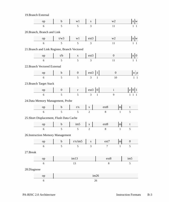
19.Branch External
20.Branch, Branch and Link
21.Branch and Link Register, Branch Vectored
22.Branch Vectored External
23.Branch Target Stack
24.Data Memory Management, Probe
25.Short Displacement, Flush Data Cache
26.Instruction Memory Management
27.Break
28.Diagnose
op b w1 s w2 n w
6 5 5 3 11 1 1
op t/w3 w1 ext3 w2 n w
6 5 5 3 11 1 1
op t/b x ext3 0 n 0
6 5 5 3 11 1 1
op b 0 ext3 1 0 n p
6 5 5 3 1 10 1 1
op 0 r ext3 0 i e 0 1
6 5 5 3 1 9 1 1 1
op b r/x s ext8 m t
6 5 5 2 8 1 5
op b im5 s ext8 m t
6 5 5 2 8 1 5
op b r/x/im5 s ext7 m 0
6 5 5 3 7 1 5
op im13 ext8 im5
6 13 8 5
op im26
6 26
B-3PA-RISC 2.0 Architecture Instruction Formats

29.Move to/from Space Register
30.Load Space ID
31.Move to Control Register
32.Move from Control Register
33.System Control
34.Special Operation Zero
35.Special Operation One
36.Special Operation Two
37.Special Operation Three
38.Coprocessor Operation
op rv r s ext8 t
6 5 5 3 8 5
op b rv s 0 ext8 t
6 5 5 2 1 8 5
op t r rv ext8 0
6 5 5 3 8 5
op r 0 rv e rv ext8 t
6 5 5 1 1 1 8 5
op b/im5 r/im5 0 ext8 t
6 5 5 3 8 5
op sop1 0 sfu n sop2
6 15 2 3 1 5
op sop 1 sfu n t
6 15 2 3 1 5
op r sop1 2 sfu n sop2
6 5 10 2 3 1 5
op r2 r1 sop1 3 sfu n sop2
6 5 5 5 2 3 1 5
op sop1 uid n sop2
6 17 3 1 5
B-4 Instruction Formats PA-RISC 2.0 Architecture

39.Coprocessor Indexed Loads
40.Coprocessor Indexed Stores
41.Coprocessor Short Displacement Loads
42.Coprocessor Short Displacement Stores
43.Floating-point Load and Store Word
44.Floating-point Load and Store Word Modify
45.Floating-point Operation Zero, Major Opcode 0C
46.Floating-point Operation One, Major Opcode 0C
47.Floating-point Operation Two, Major Opcode 0C
48.Floating-point Operation Three, Major Opcode 0C
op b x s u 0 cc 0 uid m t
6 5 5 2 1 1 2 1 3 1 5
op b x s u 0 cc 1 uid m r
6 5 5 2 1 1 2 1 3 1 5
op b im5 s a 1 cc 0 uid m t
6 5 5 2 1 1 2 1 3 1 5
op b im5 s a 1 cc 1 uid m r
6 5 5 2 1 1 2 1 3 1 5
op b t/r s im11a e h i
6 5 5 2 11 1 1 1
op b t/r s im11a a h i
6 5 5 2 11 1 1 1
op r 0 sop fmt 0 0 0 t
6 5 5 3 2 2 3 1 5
op r 0 sop df sf 1 0 0 t
6 5 3 3 2 2 2 3 1 5
op r1 r2 sop fmt 2 0 n c
6 5 5 3 2 2 3 1 5
op r1 r2 sop fmt 3 0 0 t
6 5 5 3 2 2 3 1 5
B-5PA-RISC 2.0 Architecture Instruction Formats

49.Floating-point Operation Zero, Major Opcode 0E
50.Floating-point Operation One, Major Opcode 0E
51.Floating-point Operation Two, Major Opcode 0E
52.Floating-point Operation Three, Major Opcode 0E
53.Floating-point Multiple-operation
54.Floating-point Fused-operation
55.Performance Monitor
op r 0 sop 0 f 0 0 r t 0 t
6 5 5 3 1 1 2 1 1 1 1 5
op r 0 sop 0 df 0 sf 1 0 r t 0 t
6 5 3 3 1 1 1 1 2 1 1 1 1 5
op r1 r2 sop r2 f 2 0 r1 0 0 c
6 5 5 3 1 1 2 1 1 1 1 5
op r1 r2 sop r2 f 3 x r1 t 0 t
6 5 5 3 1 1 2 1 1 1 1 5
op rm1 rm2 ta ra f tm
6 5 5 5 5 1 5
op rm1 rm2 ra r2 f ra r1 t e t
6 5 5 3 1 1 3 1 1 1 5
op rv sub 2 n rv
6 12 5 3 1 5
B-6 Instruction Formats PA-RISC 2.0 Architecture

of the. An
es,
The field names used in the previous instruction format layouts are described in Table B-1. Somefield names may be followed by one or two digits. Those digits indicate the length of the fieldexample of a field name may beim5 which indicates the field is a 5-bit immediate value. But nam
B-7PA-RISC 2.0 Architecture Instruction Formats

such asr1, which refers to the first source register field, are the actual field names.
Table B-1. Field Names for Instruction Formats
Field Description
a modify before/after bit
b base register
c condition specifier
cc cache control hint
cl, clen complement of extract/deposit length
cp, cpos complement of deposit/shift bit position
d word/doubleword bit
df floating-point destination format
e, ea, eb, ec, ed, orext
operation code extension
f condition negation bit
f or fmt floating-point data format
h floating-point register half
im immediate value
m modify bit
n nullify bit
nz deposit zero/not zero bit
op operation code
p extract/deposit/shift bit position
pos extract bit position
r, r1, or r2 source register
ra, rm1, or rm2 floating-point source register
rv reserved instruction field
s 2 or 3 bit space register
sa shift amount
se extract sign-extend bit
sf floating-point source format
sfu special function unit number
sop, sop1, or sop2 special function unit or coprocessor operation
t, ta, or tm target register
u shift index bit
uid coprocessor unit identifier
w, w1, w2, or w3 word offset/word offset part
x index register
B-8 Instruction Formats PA-RISC 2.0 Architecture

es.
truction, where shown
C Operation Codes
This appendix provides a complete description of all of the PA-RISC 2.0 instruction operation cod
Major Opcode Assignments
The major opcode assignments are listed in Table C-1. Instructions are shown in uppercase. Insclasses are capitalized. Extensions of the major opcodes can be found in the tables indicatedapplicable. In the following discussions of opcode extensions the major opcode class names arein parentheses.
C-1PA-RISC 2.0 Architecture Operation Codes

Table C-1. Major Opcode Assignments
bits 2:5bits 0:1
0 1 2 3
0System_op(Table C-2)
LDB CMPB (true) BB (sar)
1Mem_Mgmt
(Tables C-3 andC-4)
LDH CMPIB (true) BB
2Arith/Log
(Table C-5)LDW CMPB (false) MOVB
3Index_Mem(Table C-6)
LDW (mod) CMPIB (false) MOVIB
4SPOPn
(Table C-15)Load_dw
(Table C-7)CMPICLR
Sh_Ex_Dep(Tables C-10
and C-11)
5 DIAG —Subi
(Table C-9)
Sh_Ex_Dep(Tables C-10
and C-11)
6 FMPYADD FLDW (mod) FMPYSUBSh_Ex_Dep(Table C-10)
7 —Load_w
(Table C-8)CMPB
(dw true)—
8 LDIL STBADDB(true)
BE
9Copr_w
(Table C-14)STH
ADDIB(true)
BE,L
A ADDIL STWADDB(false)
Branch(Table C-13)
BCopr_dw
(Table C-14)STW (mod)
ADDIB(false)
CMPIB (dw)
C COPRStore_dw
(Table C-7)Addi
(Table C-9)Sh_Ex_Dep(Table C-10)
D LDO —Addi
(Table C-9)Sh_Ex_Dep(Table C-10)
EFloat
(Tables C-20through C-24)
FSTW (mod)Fp_fused
(Table C-25)Multimedia(Table C-12)
FProduct Specific
Store_w(Table C-8)
CMPB(dw false)
—
C-2 Operation Codes PA-RISC 2.0 Architecture

d. The
-2 listsode the
Opcode Extension Assignments
Many instructions require both a major opcode and an opcode extension to be uniquely identifieextension can be one to nine bits, depending on the major opcode.
System Control Instructions (System_op)
Figure C-1 shows the format of the system control instructions (major opcode 00) and Table Cthe opcode extensions. Bits 19:21 encode the source of the operation and bits 24:26 encdestination.
05 19 26
00 b/r/ext5 ext5 0/s ext8 t
6 5 5 3 8 5
Figure C-1. Format for System Control Instructions
Table C-2. System Control Instructions
Instruction
Opcode Extension
hex binary hex
bits0:5
bit17
bits19:21
bits22:23
bits24:26
bits19:26
bits11:15
BREAK 00 – 000 00 000 00 im5SYNC 00 0 001 00 000 20 0SYNCDMA 00 0 001 00 000 20 10RFI 00 rv 011 00 000 60 rvRFI,R 00 rv 011 00 101 65 rvSSM 00 0 011 01 011 6B iRSM 00 0 011 10 011 73 iMTSM 00 0 110 00 011 C3 rLDSID 00 – 100 00 101 85 rvMTSP 00 – 110 00 001 C1 rMFSP 00 – 001 00 101 25 0MFIA 00 rv 101 00 101 A5 0MTCTL 00 rv 110 00 010 C2 rMTSARCM 00 rv 110 00 110 C6 rMFCTL 00 0 010 00 101 45 0MFCTL,W 00 1 010 00 101 45 0
C-3PA-RISC 2.0 Architecture Operation Codes
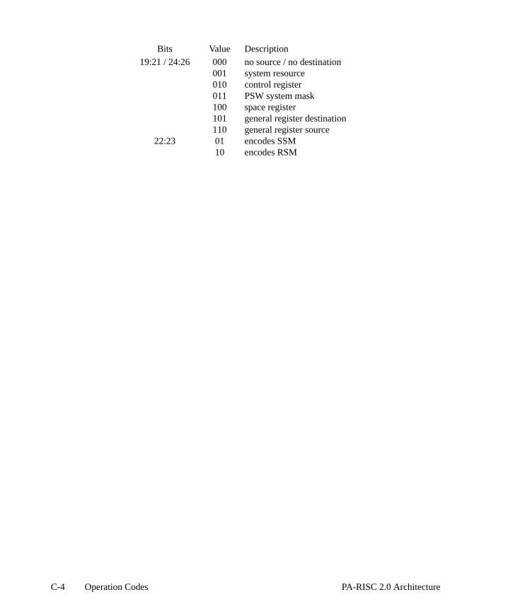
Bits Value Description
19:21 / 24:26 000 no source / no destination001 system resource010 control register011 PSW system mask100 space register101 general register destination110 general register source
22:23 01 encodes SSM10 encodes RSM
C-4 Operation Codes PA-RISC 2.0 Architecture

opcode. The
C-4 onaches.
Memory Management Instructions (Mem_Mgmt)
Figure C-2 shows the format of the memory management instructions (major opcode 01). The extensions (bits 19:26) for instruction memory management instructions are listed in Table C-3opcode extensions (bits 18:26) for data memory management instructions are listed in Tablepage C-6. This group includes instructions that access the translation lookaside buffers and the c
Instruction Memory Management
05 19 25 27 31
01 b r/x/im5 s ext7 m ext5
6 5 5 3 7 1 5
Data Memory Management, Probe
05 18 25 27 31
01 b r/x/im5 s ext8 m ext5
6 5 5 2 8 1 5
Figure C-2. Formats for Memory Management Instructions
Table C-3. Instruction Memory Management Instructions
Instruction
Opcode Extension Modify
hex binary hex binary
bits0:5
bit19
bits20:21
bits22:24
bit25
bits19:25
bits27:31
bit26
IITLBT 01 0 10 000 0 20 0 0PITLB 01 0 00 100 0 08 rv mPITLBE 01 0 00 100 1 09 rv mPITLB,L 01 0 01 100 0 18 rv mFIC,0A 01 0 00 101 0 0A rv mFICE 01 0 00 101 1 0B rv m
Bits Value Description
19 0 instruction memory management22:24 000 insert instruction
100 purge TLB instruction101 flush instruction
22 1 modify (bit 26) enable24 1 nonprivileged instruction26 m modification is allowed for this instruction
C-5PA-RISC 2.0 Architecture Operation Codes

Table C-4. Data Memory Management Instructions
Instruction
Opcode Extension Modify
hex binary hex binary
bits0:5
bit18
bit19
bits20:21
bits22:24
bit25
bits18:25
bits27:31
bit26
IDTLBT 01 0 1 10 000 0 60 0 0PDTLB 01 0 1 00 100 0 48 rv mPDTLBE 01 0 1 00 100 1 49 rv mPDTLB,L 01 0 1 01 100 0 58 rv mFDC (index) 01 0 1 00 101 0 4A rv mFDC (imm) 01 1 1 00 101 0 CA rv 0FDCE 01 0 1 00 101 1 4B rv mPDC 01 0 1 00 111 0 4E 0 mFIC,4F 01 0 1 00 111 1 4F 0 mPROBE,R 01 0 1 00 011 0 46 t 0PROBEI,R 01 1 1 00 011 0 C6 t 0PROBE,W 01 0 1 00 011 1 47 t 0PROBEI,W 01 1 1 00 011 1 C7 t 0LPA 01 0 1 00 110 1 4D t mLCI 01 0 1 00 110 0 4C t 0
Bits Value Description
18 0 non-immediate value1 immediate value
19 1 data memory management22:24 000 insert instruction
011 probe instruction100 purge TLB instruction101 flush instruction110 load instruction111 purge cache instruction
22 1 modify (bit 26) enable23 1 store result24 1 nonprivileged instruction26 m modification is allowed for this instruction
C-6 Operation Codes PA-RISC 2.0 Architecture

r the
Arithmetic/Logical Instructions (Arith/Log)
Figure C-3 shows the format of the arithmetic/logical instructions. The opcode extensions foarithmetic/logical instructions (major opcode 02) are listed in Table C-5.
05 20 25
02 r2 r1 c f ext6 d t
6 5 5 3 1 6 1 5
Figure C-3. Format for Arithmetic/Logical Instructions
Table C-5. Arithmetic/Logical Instructions
Instruction
Opcode Extension
hex binary hex
bits0:5
bits20:21
bits22:25
bits20:25
ADD 02 01 1000 18ADD,L 02 10 1000 28ADD,TSV 02 11 1000 38ADD,C 02 01 1100 1CADD,C,TSV 02 11 1100 3CSHLADD (1) 02 01 1001 19SHLADD,L (1) 02 10 1001 29SHLADD,TSV (1) 02 11 1001 39SHLADD (2) 02 01 1010 1ASHLADD,L (2) 02 10 1010 2ASHLADD,TSV (2) 02 11 1010 3ASHLADD (3) 02 01 1011 1BSHLADD,L (3) 02 10 1011 2BSHLADD,TSV (3) 02 11 1011 3BSUB 02 01 0000 10SUB,TSV 02 11 0000 30SUB,TC 02 01 0011 13SUB,TSV,TC 02 11 0011 33SUB,B 02 01 0100 14SUB,B,TSV 02 11 0100 34DS 02 01 0001 11ANDCM 02 00 0000 00AND 02 00 1000 08OR 02 00 1001 09XOR 02 00 1010 0AUXOR 02 00 1110 0ECMPCLR 02 10 0010 22UADDCM 02 10 0110 26
C-7PA-RISC 2.0 Architecture Operation Codes

UADDCM,TC 02 10 0111 27DCOR 02 10 1110 2EDCOR,I 02 10 1111 2FHADD 02 00 1111 0FHADD,SS 02 00 1101 0DHADD,US 02 00 1100 0CHSUB 02 00 0111 07HSUB,SS 02 00 0101 05HSUB,US 02 00 0100 04HAVG 02 00 1011 0BHSHLADD (1) 02 01 1101 1DHSHLADD (2) 02 01 1110 1EHSHLADD (3) 02 01 1111 1FHSHRADD (1) 02 01 0101 15HSHRADD (2) 02 01 0110 16HSHRADD (3) 02 01 0111 17
Bits Value Description
20:21 00 unit/logical; do not set carry/borrow bits.01 arithmetic; set carry/borrow bits; do not trap.10 unit/logical; do not set carry/borrow bits.11 arithmetic; set carry/borrow bits; trap on overflow.
Table C-5. Arithmetic/Logical Instructions (Continued)
Instruction
Opcode Extension
hex binary hex
bits0:5
bits20:21
bits22:25
bits20:25
C-8 Operation Codes PA-RISC 2.0 Architecture

ns. Theuctionsm the
Indexed and Short Displacement Load/Store Instructions (Index_Mem)
Figure C-4 shows the formats of the indexed and short displacement load and store instructioopcode extensions (bits 22:25) for indexed and short displacement memory reference instr(major opcode 03) are listed in Table C-6. The short displacement forms are distinguished froindexed instructions by bit 19 (0=indexed, 1=short).
Indexed Loads
05 19 22 25
03 b x s u 0 cc ext4 m t
6 5 5 2 1 1 2 4 1 5
Short Displacement Loads
05 19 22 25
03 b im5 s a 1 cc ext4 m t
6 5 5 2 1 1 2 4 1 5
Short Displacement Stores, Store Bytes Short
05 19 22 25
03 b r s a 1 cc ext4 m im5
6 5 5 2 1 1 2 4 1 5
Figure C-4. Formats for Indexed and Short Displacement Load/Store Instructions
C-9PA-RISC 2.0 Architecture Operation Codes
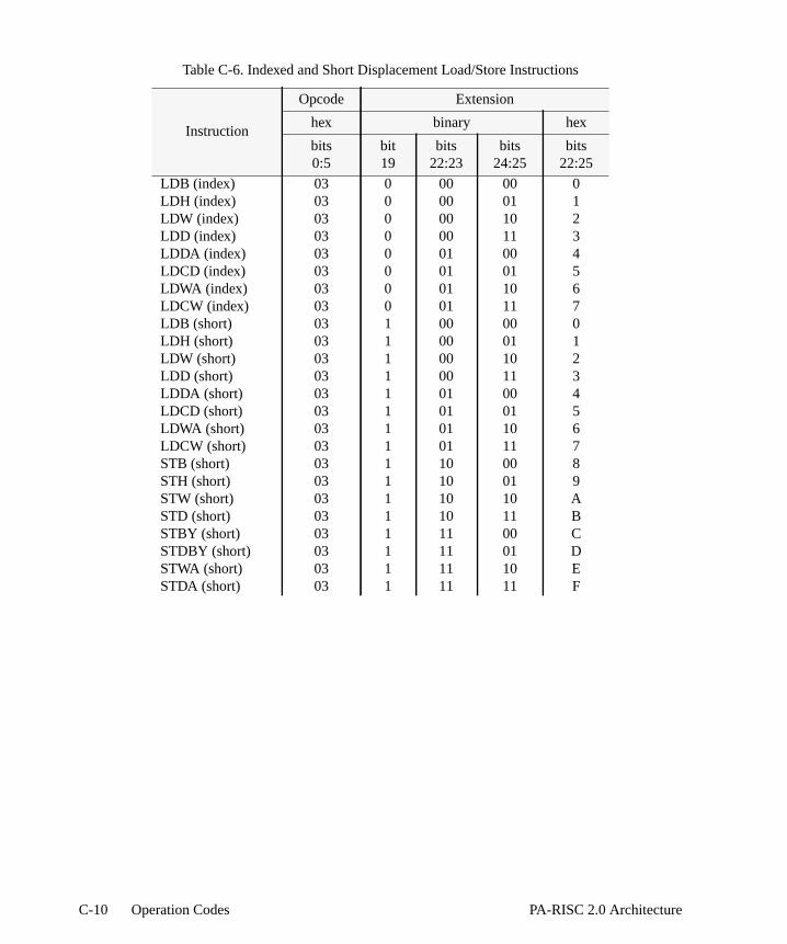
Table C-6. Indexed and Short Displacement Load/Store Instructions
Instruction
Opcode Extension
hex binary hex
bits0:5
bit19
bits22:23
bits24:25
bits22:25
LDB (index) 03 0 00 00 0LDH (index) 03 0 00 01 1LDW (index) 03 0 00 10 2LDD (index) 03 0 00 11 3LDDA (index) 03 0 01 00 4LDCD (index) 03 0 01 01 5LDWA (index) 03 0 01 10 6LDCW (index) 03 0 01 11 7LDB (short) 03 1 00 00 0LDH (short) 03 1 00 01 1LDW (short) 03 1 00 10 2LDD (short) 03 1 00 11 3LDDA (short) 03 1 01 00 4LDCD (short) 03 1 01 01 5LDWA (short) 03 1 01 10 6LDCW (short) 03 1 01 11 7STB (short) 03 1 10 00 8STH (short) 03 1 10 01 9STW (short) 03 1 10 10 ASTD (short) 03 1 10 11 BSTBY (short) 03 1 11 00 CSTDBY (short) 03 1 11 01 DSTWA (short) 03 1 11 10 ESTDA (short) 03 1 11 11 F
C-10 Operation Codes PA-RISC 2.0 Architecture

s. The(major
Load/Store Doubleword Instructions (Load_dw and Store_dw)
Figure C-5 shows the formats of the long displacement load and store doubleword instructionopcode extensions (bit 30) for long displacement load and store doubleword instructions opcodes 14 and 1C) are listed in Table C-7.
05 30
op b t/r s im10a m a e i
6 5 5 2 10 1 1 1 1
Figure C-5. Format for Load/Store Doubleword Instructions
Table C-7. Load/Store Doubleword Instructions
Instruction
Opcode Extension
hex binary
bits0:5
bit30
LDD (long) 14 0STD (long) 1C 0FLDD (long) 14 1FSTD (long) 1C 1
C-11PA-RISC 2.0 Architecture Operation Codes
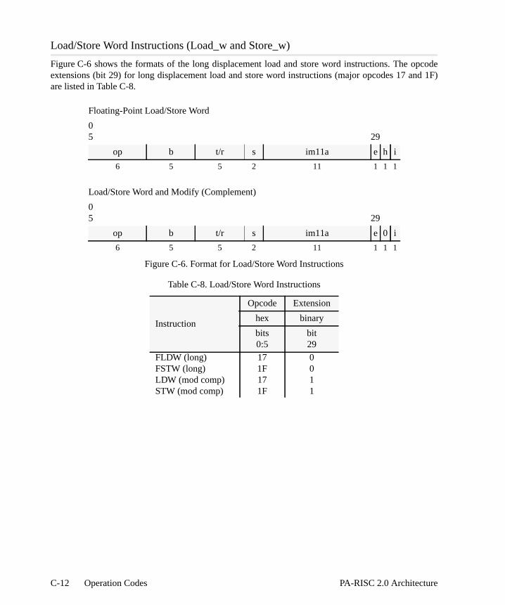
pcodend 1F)
Load/Store Word Instructions (Load_w and Store_w)
Figure C-6 shows the formats of the long displacement load and store word instructions. The oextensions (bit 29) for long displacement load and store word instructions (major opcodes 17 aare listed in Table C-8.
Floating-Point Load/Store Word
05 29
op b t/r s im11a e h i
6 5 5 2 11 1 1 1
Load/Store Word and Modify (Complement)
05 29
op b t/r s im11a e 0 i
6 5 5 2 11 1 1 1
Figure C-6. Format for Load/Store Word Instructions
Table C-8. Load/Store Word Instructions
Instruction
Opcode Extension
hex binary
bits0:5
bit29
FLDW (long) 17 0FSTW (long) 1F 0LDW (mod comp) 17 1STW (mod comp) 1F 1
C-12 Operation Codes PA-RISC 2.0 Architecture

bit 20)9. The
Arithmetic Immediate Instructions (Addi, Subi)
Figure C-7 shows the format of the arithmetic immediate instructions. The opcode extensions (for the arithmetic immediate instructions (major opcodes 25, 2C, and 2D) are listed in Table C-extension field,e, determines whether or not the instruction traps on overflow.
05 20
op r t c f e1 im11
6 5 5 3 1 1 11
Figure C-7. Format for Arithmetic Immediate Instructions
Table C-9. Arithmetic Immediate Instructions
Instruction
Opcode Extension
hex binary
bits0:5
bit20
ADDI 2D 0ADDI,TC 2C 0SUBI 25 0ADDI,TSV 2D 1ADDI,TSV,TC 2C 1SUBI,TSV 25 1
C-13PA-RISC 2.0 Architecture Operation Codes
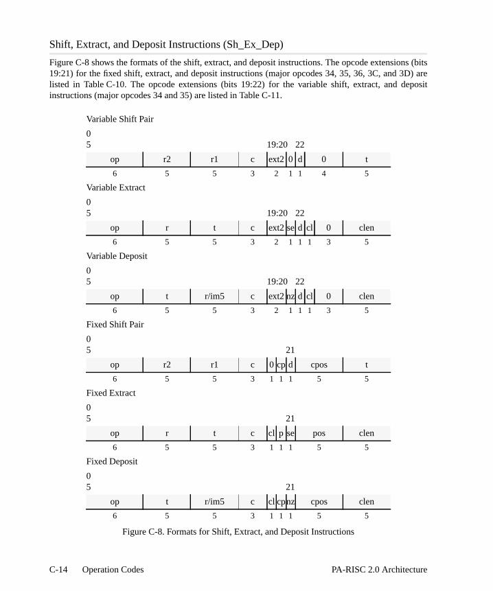
ns (bitsD) areeposit
Shift, Extract, and Deposit Instructions (Sh_Ex_Dep)
Figure C-8 shows the formats of the shift, extract, and deposit instructions. The opcode extensio19:21) for the fixed shift, extract, and deposit instructions (major opcodes 34, 35, 36, 3C, and 3listed in Table C-10. The opcode extensions (bits 19:22) for the variable shift, extract, and dinstructions (major opcodes 34 and 35) are listed in Table C-11.
Variable Shift Pair
05 19:20 22
op r2 r1 c ext2 0 d 0 t
6 5 5 3 2 1 1 4 5
Variable Extract
05 19:20 22
op r t c ext2se d cl 0 clen
6 5 5 3 2 1 1 1 3 5
Variable Deposit
05 19:20 22
op t r/im5 c ext2nz d cl 0 clen
6 5 5 3 2 1 1 1 3 5
Fixed Shift Pair
05 21
op r2 r1 c 0 cp d cpos t
6 5 5 3 1 1 1 5 5
Fixed Extract
05 21
op r t c cl p se pos clen
6 5 5 3 1 1 1 5 5
Fixed Deposit
05 21
op t r/im5 c cl cpnz cpos clen
6 5 5 3 1 1 1 5 5
Figure C-8. Formats for Shift, Extract, and Deposit Instructions
C-14 Operation Codes PA-RISC 2.0 Architecture

Table C-10. Fixed Shift/Extract/Deposit Instructions
Instruction
Opcode Extension
hex binary binary binary
bits0:5
bit19
bit20
bit21
SHRPD 34 0 p 1SHRPW 34 0 1 0EXTRD 36 cl p seEXTRW 34 1 1 seDEPD 3C cl cp nzDEPDI 3D cl cp nzDEPW 35 0 1 nzDEPWI 35 1 1 nz
Table C-11. Variable Shift/Extract/Deposit Instructions
Instruction
Opcode Extension
hex binary hex binary binary
bits0:5
bits19:20
bits19:20
bit21
bit22
SHRPD 34 00 0 0 1SHRPW 34 00 0 0 0EXTRD 34 10 2 se 1EXTRW 34 10 2 se 0DEPD 35 00 0 nz 1DEPDI 35 10 2 nz 1DEPW 35 00 0 nz 0DEPWI 35 10 2 nz 0
C-15PA-RISC 2.0 Architecture Operation Codes

17:18,
Multimedia Instructions (Multimedia)
Figure C-9 shows the formats of the multimedia instructions. The opcode extensions (bits 16, and 20:21) for the multimedia instructions (major opcode 3E) are listed in Table C-12
Halfword Permute
05 16 20:21
3E r r 0 c0 0 c1 c2 c3 0 t
6 5 5 1 2 1 2 2 2 1 5
Halfword Shifts
05 16 20:21
3E 0/r r/0 1 ea 0 eb sa 0 t
6 5 5 1 2 1 2 4 1 5
Halfword Mix
05 16 20:21
3E r2 r1 1 ea 0 eb 0 0 t
6 5 5 1 2 1 2 4 1 5
Figure C-9. Formats for Multimedia Instructions
Table C-12. Multimedia Instructions
Instruction
Opcode Extension
hex binary hex
bits0:5
bit16
bits17:18
bits20:21
bits17:18
bits20:21
PERMH 3E 0 – – – –HSHL 3E 1 00 10 0 2HSHR,U 3E 1 10 10 2 2HSHR,S 3E 1 10 11 2 3MIXW,L 3E 1 00 00 0 0MIXW,R 3E 1 10 00 2 0MIXH,L 3E 1 00 01 0 1MIXH,R 3E 1 10 01 2 1
C-16 Operation Codes PA-RISC 2.0 Architecture

s (bits3.
Unconditional Branch Instructions (Branch)
Figure C-10 shows the formats of the unconditional branch instructions. The opcode extension16:18 and 31) for the unconditional branch instructions (major opcode 3A) are listed in Table C-1
Branch
05 16 18 31
3A t/w3 w1 ext3 w2 n w
6 5 5 3 11 1 1
Branch Vectored External
05 16 18 31
3A b 0 ext3 1 rv n rv
6 5 5 3 1 10 1 1
Branch and Link Register, Branch Vectored
05 16 18 31
3A t/b 0/x ext3 0 rv n rv
6 5 5 3 1 10 1 1
Figure C-10. Formats for Unconditional Branch Instructions
Table C-13. Unconditional Branch Instructions
Instruction
Opcode Extension
hex binary hex binary
bits0:5
bits16:18
bits16:18
bit19
B,L 3A 000 0 –B,GATE 3A 001 1 –B,L,PUSH 3A 100 4 –B,L (long) 3A 101 5 –BLR 3A 010 2 0BV 3A 110 6 0BVE 3A 110 6 1BVE,L 3A 111 7 1
C-17PA-RISC 2.0 Architecture Operation Codes

ensionse C-14.es theuished (0 =
Coprocessor Loads and Stores (Copr_w and Copr_dw)
Figure C-11 shows the formats of the coprocessor load and store instructions. The opcode extfor the coprocessor memory reference instructions (major opcodes 09 and 0B) are listed in TablOpcode 09 indicates the instruction operates on word data (Copr_w). Opcode 0B indicatinstruction operates on doubleword data (Copr_dw). The short displacement forms are distingfrom the indexed instructions by bit 19 (0 = indexed; 1 = short) and loads from stores by bit 22load; 1 = store).
Coprocessor Indexed Loads
05 19 22
op b x s u 0 cc 0 uid m t
6 5 5 2 1 1 2 1 3 1 5
Coprocessor Indexed Stores
05 19 22
op b x s u 0 cc 1 uid m r
6 5 5 2 1 1 2 1 3 1 5
Coprocessor Short Loads
05 19 22
op b im5 s a 1 cc 0 uid m t
6 5 5 2 1 1 2 1 3 1 5
Coprocessor Short Stores
05 19 22
op b im5 s a 1 cc 1 uid m r
6 5 5 2 1 1 2 1 3 1 5
Figure C-11. Formats for Coprocessor Load/Store Instructions
C-18 Operation Codes PA-RISC 2.0 Architecture

Table C-14. Coprocessor Load and Store Instructions
Instruction
Opcode Extension
hex binary
bits0:5
bit19
bit22
CLDW (index) 09 0 0CLDD (index) 0B 0 0CSTW (index) 09 0 1CSTD (index) 0B 0 1CLDW (short) 09 1 0CLDD (short) 0B 1 0CSTW (short) 09 1 1CSTD (short) 0B 1 1
C-19PA-RISC 2.0 Architecture Operation Codes

for the
Special Function Unit Instructions
Figure C-12 shows the formats of the special function unit instructions. The opcode extensions special function unit instructions (major opcode 04) are listed in Table C-15.
Special Operation Zero
05 21:22
04 sop1 0 sfu n sop2
6 15 2 3 1 5
Special Operation One
05 21:22
04 sop 1 sfu n t
6 15 2 3 1 5
Special Operation Two
05 21:22
04 r sop1 2 sfu n sop2
6 5 10 2 3 1 5
Special Operation Three
05 21:22
04 r1 r2 sop1 3 sfu n sop2
6 5 5 5 2 3 1 5
Figure C-12. Formats for Special Function Unit (SFU) Instructions
Table C-15. Special Function Unit (SFU) Instructions
Instruction
Opcode Extension
hex binary hex
bits0:5
bits21:22
bits21:22
SPOP0 04 00 0SPOP1 04 01 1SPOP2 04 10 2SPOP3 04 11 3
C-20 Operation Codes PA-RISC 2.0 Architecture

ctions.0C, uid
Floating-Point Coprocessor Operation Instructions
Figures C-13, C-14, and C-15 show the formats of the floating-point coprocessor operation instruThe opcode extensions for the floating-point coprocessor operation instructions (major opcode 0, major opcode 0E, and major opcode 2E) are listed in Tables C-16 through C-24.
Major Opcode 0C
Floating-Point Operation Zero
05 16 18 21:22 26
0C r 0 sub fmt 0 0 0 t
6 5 5 3 2 2 3 1 5
Floating-Point Operation One
05 14 16 21:22 26
0C r 0 sub df sf 1 0 0 t
6 5 3 3 2 2 2 3 1 5
Floating-Point Operation Two
05 16 18 21:22 26
0C r1 r2 sub fmt 2 0 n c
6 5 5 3 2 2 3 1 5
Floating-Point Operation Three
05 16 18 21:22 26
0C r1 r2 sub fmt 3 0 0 t
6 5 5 3 2 2 3 1 5
Figure C-13. Formats for Floating-Point Operations - Major Opcode 0C
C-21PA-RISC 2.0 Architecture Operation Codes
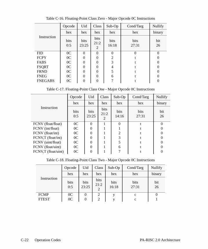
Table C-16. Floating-Point Class Zero - Major Opcode 0C Instructions
Instruction
Opcode Uid Class Sub-Op Cond/Targ Nullify
hex hex hex hex hex binary
bits0:5
bits23:25
bits21:2
2
bits16:18
bits27:31
bit26
FID 0C 0 0 0 0 0FCPY 0C 0 0 2 t 0FABS 0C 0 0 3 t 0FSQRT 0C 0 0 4 t 0FRND 0C 0 0 5 t 0FNEG 0C 0 0 6 t 0FNEGABS 0C 0 0 7 t 0
Table C-17. Floating-Point Class One - Major Opcode 0C Instructions
Instruction
Opcode Uid Class Sub-Op Cond/Targ Nullify
hex hex hex hex hex binary
bits0:5
bits23:25
bits21:2
2
bits14:16
bits27:31
bit26
FCNV (float/float) 0C 0 1 0 t 0FCNV (int/float) 0C 0 1 1 t 0FCNV (float/int) 0C 0 1 2 t 0FCNV,T (float/int) 0C 0 1 3 t 0FCNV (uint/float) 0C 0 1 5 t 0FCNV (float/uint) 0C 0 1 6 t 0FCNV,T (float/uint) 0C 0 1 7 t 0
Table C-18. Floating-Point Class Two - Major Opcode 0C Instructions
Instruction
Opcode Uid Class Sub-Op Cond/Targ Nullify
hex hex hex hex hex binary
bits0:5
bits23:25
bits21:2
2
bits16:18
bits27:31
bit26
FCMP 0C 0 2 y c 0FTEST 0C 0 2 y c 1
C-22 Operation Codes PA-RISC 2.0 Architecture
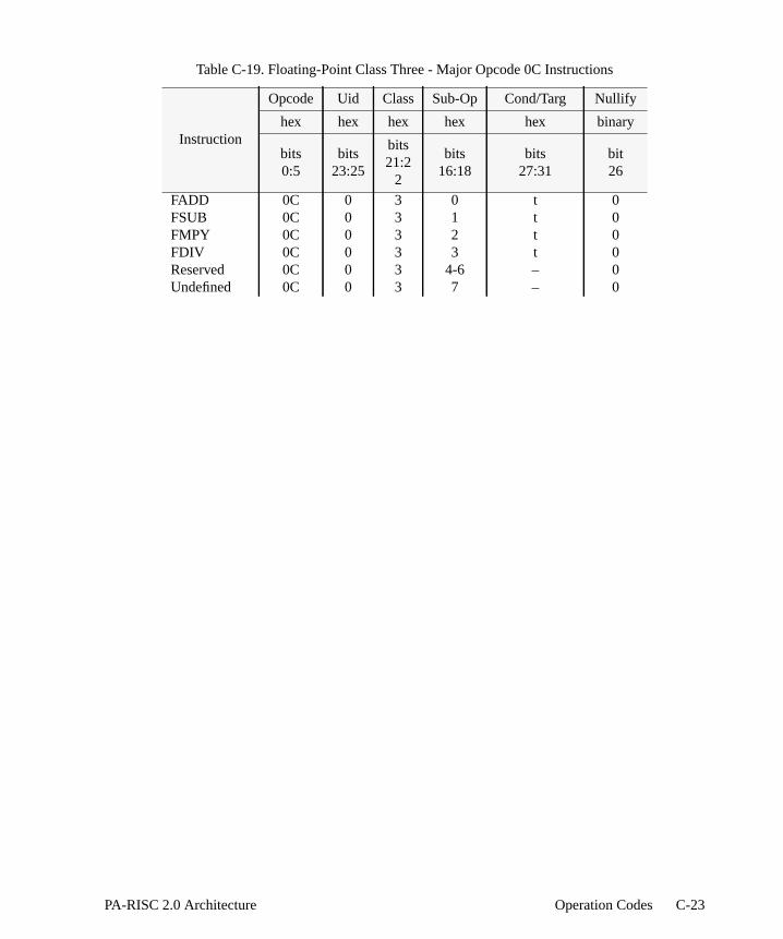
Table C-19. Floating-Point Class Three - Major Opcode 0C Instructions
Instruction
Opcode Uid Class Sub-Op Cond/Targ Nullify
hex hex hex hex hex binary
bits0:5
bits23:25
bits21:2
2
bits16:18
bits27:31
bit26
FADD 0C 0 3 0 t 0FSUB 0C 0 3 1 t 0FMPY 0C 0 3 2 t 0FDIV 0C 0 3 3 t 0Reserved 0C 0 3 4-6 – 0Undefined 0C 0 3 7 – 0
C-23PA-RISC 2.0 Architecture Operation Codes

Major Opcode 0E (Float)
Floating-Point Operation Zero
05 16 18 21:22 26
0E r 0 sub 0 f 0 0 r t 0 t
6 5 5 3 1 1 2 1 1 1 1 5
Floating-Point Operation One
05 14 16 21:22 26
0E r 0 sub 0 df 0 sf 1 0 r t 0 t
6 5 3 3 1 1 1 1 2 1 1 1 1 5
Floating-Point Operation Two
05 16 18 21:22 26
0E r1 r2 sub r2 f 2 0 r1 0 0 c
6 5 5 3 1 1 2 1 1 1 1 5
Floating-Point Operation Three
05 16 18 21:22 26
0E r1 r2 sub r2 f 3 0 r1 t 0 t
6 5 5 3 1 1 2 1 1 1 1 5
Fixed-Point Operation Three
05 16 18 21:22 26
0E r1 r2 sub r2 f 3 1 r1 t 0 t
6 5 5 3 1 1 2 1 1 1 1 5
Figure C-14. Formats for Floating-Point Operations - Major Opcode 0E
C-24 Operation Codes PA-RISC 2.0 Architecture

Table C-20. Floating-Point Class Zero - Major Opcode 0E Instructions
Instruction
Opcode Class Sub-Op Fixed Nullify Format Cond/Targ
hex hex hex binary binary hex hex
bits0:5
bits21:2
2
bits16:18
bit23
bit26
bits19:20
bits25,27:31
FCPY 0E 0 2 0 0 fmt tFABS 0E 0 3 0 0 fmt tFSQRT 0E 0 4 0 0 fmt tFRND 0E 0 5 0 0 fmt tFNEG 0E 0 6 0 0 fmt tFNEGABS 0E 0 7 0 0 fmt t
Table C-21. Floating-Point Class One - Major Opcode 0E Instructions
Instruction
Opcode Class Sub-Op Fixed Nullify Format Cond/Targ
hex hex hex binary binary hex hex
bits0:5
bits21:2
2
bits14:16
bit23
bit26
bits17:20
bits25,27:31
FCNV (float/float) 0E 1 0 0 0 df,sf tFCNV (int/float) 0E 1 1 0 0 df,sf tFCNV (float/int) 0E 1 2 0 0 df,sf tFCNV,T (float/int) 0E 1 3 0 0 df,sf tFCNV (uint/float) 0E 1 5 0 0 df,sf tFCNV (float/uint) 0E 1 6 0 0 df,sf tFCNV,T (float/uint) 0E 1 7 0 0 df,sf t
Table C-22. Floating-Point Class Two - Major Opcode 0E Instructions
Instruction
Opcode Class Sub-Op Fixed Nullify Format Cond/Targ
hex hex hex binary binary binary hex
bits0:5
bits21:2
2
bits16:18
bit23
bit26
bit20
bits25,27:31
FCMP 0E 2 y 0 0 f 0,c
C-25PA-RISC 2.0 Architecture Operation Codes

Table C-23. Floating-Point Class Three - Major Opcode 0E Instructions
Instruction
Opcode Class Sub-Op Fixed Nullify Format Cond/Targ
hex hex hex binary binary binary hex
bits0:5
bits21:2
2
bits16:18
bit23
bit26
bit20
bits25,27:31
FADD 0E 3 0 0 0 f tFSUB 0E 3 1 0 0 f tFMPY 0E 3 2 0 0 f tFDIV 0E 3 3 0 0 f tUndefined 0E 3 4 0 0 – –Reserved 0E 3 5-6 0 0 – –Undefined 0E 3 7 0 0 – –
Table C-24. Fixed-Point Class Three - Major Opcode 0E Instructions
Instruction
Opcode Class Sub-Op Fixed Nullify Format Cond/Targ
hex hex hex binary binary binary hex
bits0:5
bits21:2
2
bits16:18
bit23
bit26
bit20
bits25,27:31
XMPYU 0E 3 2 1 0 0 t
C-26 Operation Codes PA-RISC 2.0 Architecture

Major Opcode 2E (Fp_fused)
05 20 26
2E r1 r2 r3 r2 f r3 r1 t s t
6 5 5 3 1 1 3 1 1 1 5
Figure C-15. Format for Floating-Point Fused-Operation Instructions
Table C-25. Floating-Point Fused-Operation Instructions
Instruction
Opcode Sub-Op Format
hex binary binary
bits0:5
bit26
bit20
FMPYFADD 2E 0 fFMPYNFADD 2E 1 f
C-27PA-RISC 2.0 Architecture Operation Codes
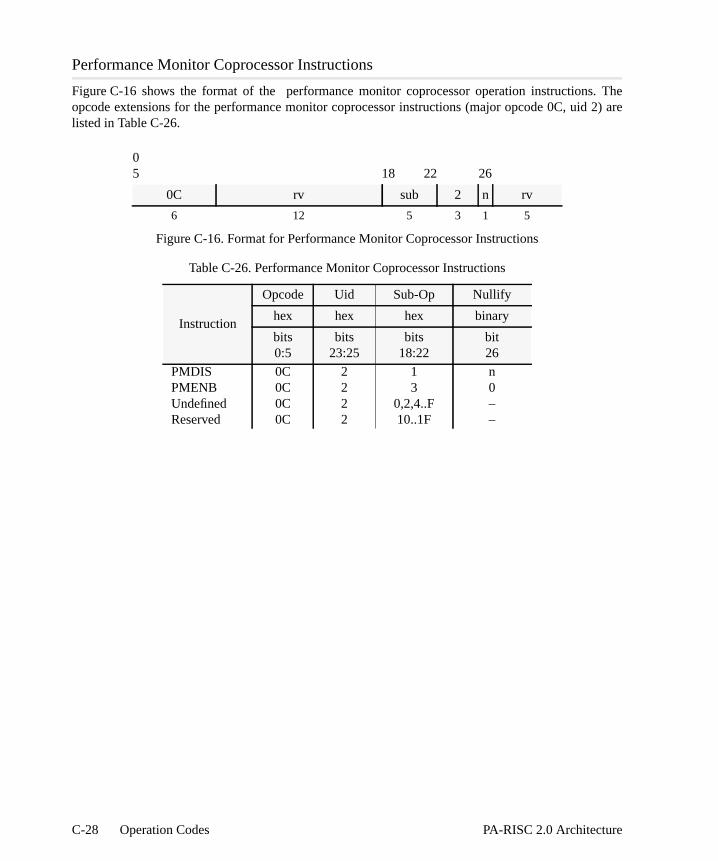
s. The 2) are
Performance Monitor Coprocessor Instructions
Figure C-16 shows the format of the performance monitor coprocessor operation instructionopcode extensions for the performance monitor coprocessor instructions (major opcode 0C, uidlisted in Table C-26.
05 18 22 26
0C rv sub 2 n rv
6 12 5 3 1 5
Figure C-16. Format for Performance Monitor Coprocessor Instructions
Table C-26. Performance Monitor Coprocessor Instructions
Instruction
Opcode Uid Sub-Op Nullify
hex hex hex binary
bits0:5
bits23:25
bits18:22
bit26
PMDIS 0C 2 1 nPMENB 0C 2 3 0Undefined 0C 2 0,2,4..F –Reserved 0C 2 10..1F –
C-28 Operation Codes PA-RISC 2.0 Architecture

s all the
lled by
erflowheword 64-bitWordhmetic
ns in
D Conditions
The condition completer field,cond, in the assembly language form of an instruction specifiecondition or the negation of a condition. This field expands in the machine language form to ficondition field,c, (normally 3 bits wide), the 1-bit negation field,f, and the 1-bit doubleword field,d, asrequired. For some instructions, the negation or doubleword attributes of the condition are controthe opcode.
This appendix defines all conditions for the instruction set.
Arithmetic/Logical Conditions
The arithmetic/logical operations generate the set of conditions as shown in Table D-1. No ovconditions result from logical operations. In the table,c is the machine language encoding indicating tcondition. While most instructions perform only doubleword arithmetic/logical operations, both and doubleword conditions are available. Doubleword conditions are computed based on theresult of the arithmetic operation, the (leftmost) carry bit of the result, and the overflow indication. conditions are computed based on the least significant 32 bits of the 64-bit result of the aritoperation, and the carry bit and overflow indication out of bit 32 of the doubleword result.
The terms signed overflow and unsigned overflow are defined for the arithmetic instructioTable D-2.
Table D-1. Arithmetic/Logical Operation Conditions
c Description
0 never; nothing1 all bits are 02 (leftmost bit is 1) xor signed overflow3 all bits are 0 or (leftmost bit is 1 xor signed overflow)
adds subtracts/compares4 no unsigned overflow unsigned overflow5 all bits are 0 or no unsigned overflow all bits are 0 or unsigned overflow6 signed overflow7 rightmost bit is 1
D-1PA-RISC 2.0 Architecture Conditions
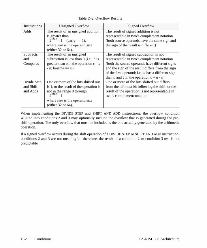
e pre-hmetic
is not
d
When implementing theDIVIDE STEP and SHIFT AND ADD instructions, the overflow conditionXORed into conditions 2 and 3 may optionally include the overflow that is generated during thshift operation. The only overflow that must be included is the one actually generated by the aritoperation.
If a signed overflow occurs during the shift operation of aDIVIDE STEP or SHIFT AND ADD instruction,conditions 2 and 3 are not meaningful; therefore, the result of a condition 2 or condition 3 testpredictable.
Table D-2. Overflow Results
Instructions Unsigned Overflow Signed Overflow
Adds The result of an unsigned additionis greater than
(carry == 1).wheresize is the operand size(either 32 or 64).
The result of signed addition is notrepresentable in two’s complement notation(both source operands have the same sign anthe sign of the result is different)
SubtractsandCompares
The result of an unsignedsubtraction is less than 0 (i.e.,b isgreater thana in the operationc = a- b; borrow == 0).
The result of signed subtraction is notrepresentable in two’s complement notation(both the source operands have different signsand the sign of the result differs from the signof the first operand; i.e.,a has a different signthanb andc in the operationc = a - b).
Divide Stepand Shiftand Adds
One or more of the bits shifted outis 1, or the result of the operation isnot in the range 0 through
wheresize is the operand size(either 32 or 64).
One or more of the bits shifted out differsfrom the leftmost bit following the shift, or theresult of the operation is not representable intwo’s complement notation.
2size
1–
2size
1–
D-2 Conditions PA-RISC 2.0 Architecture

nve
f
. The-3 and
.nguage less
Programming NoteThe figure below shows signed number addition and indicates the signed overflow conditiowhen both operands are small positive numbers, large positive numbers, large negatinumbers, or small negative numbers.
Signed overflow can occur only when adding numbers with the same sign. Addition onumbers with unlike signs will always result with a “no overflow” condition.
The interpretation of the arithmetic/logical conditions varies according to the operation performedinterpretation for all the subtracts and the register forms of comparisons are shown in Tables DD-4. The interpretation for the immediate form of comparisons are shown in Table D-5.
In these tables,cond is in assembly language format andc, f, andd are in machine language formatopd1 denotes operand 1 (an immediate value or a register’s contents) in the assembly lainstruction format andopd2 denotes operand 2 (a register’s contents). The condition, <<, “opd1 isthan opd2 (unsigned)” is equivalent to unsigned overflow in Table D-1.
GR[r1]
GR[r2]
GR[t]
smallpositivenumbers
largepositivenumbers
largenegativenumbers
smallnegativenumbers
0 0
sign
0 1
sign
1 0
sign
1 1
sign
0 0 0 1 1 0 1 1
0no
overflow 1 overflow 0 overflow 1no
overflow
D-3PA-RISC 2.0 Architecture Conditions
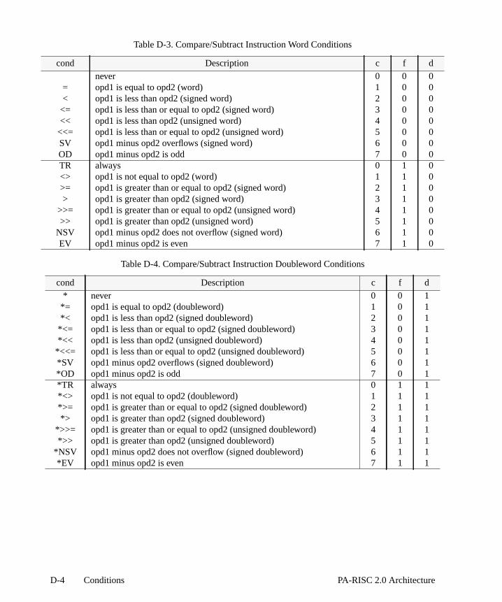
00
00
0
00
000
111
1
111
Table D-3. Compare/Subtract Instruction Word Conditions
cond Description c f d
never 0 0 0= opd1 is equal to opd2 (word) 1 0 0< opd1 is less than opd2 (signed word) 2 0
<= opd1 is less than or equal to opd2 (signed word) 3 0<< opd1 is less than opd2 (unsigned word) 4 0
<<= opd1 is less than or equal to opd2 (unsigned word) 5 0SV opd1 minus opd2 overflows (signed word) 6 0OD opd1 minus opd2 is odd 7 0 0TR always 0 1 0<> opd1 is not equal to opd2 (word) 1 1 0>= opd1 is greater than or equal to opd2 (signed word) 2 1> opd1 is greater than opd2 (signed word) 3 1
>>= opd1 is greater than or equal to opd2 (unsigned word) 4 1>> opd1 is greater than opd2 (unsigned word) 5 1
NSV opd1 minus opd2 does not overflow (signed word) 6 1EV opd1 minus opd2 is even 7 1 0
Table D-4. Compare/Subtract Instruction Doubleword Conditions
cond Description c f d
* never 0 0 1*= opd1 is equal to opd2 (doubleword) 1 0 1*< opd1 is less than opd2 (signed doubleword) 2 0 1
*<= opd1 is less than or equal to opd2 (signed doubleword) 3 0*<< opd1 is less than opd2 (unsigned doubleword) 4 0
*<<= opd1 is less than or equal to opd2 (unsigned doubleword) 5 0*SV opd1 minus opd2 overflows (signed doubleword) 6 0 1*OD opd1 minus opd2 is odd 7 0 1*TR always 0 1 1*<> opd1 is not equal to opd2 (doubleword) 1 1 1*>= opd1 is greater than or equal to opd2 (signed doubleword) 2 1*> opd1 is greater than opd2 (signed doubleword) 3 1 1
*>>= opd1 is greater than or equal to opd2 (unsigned doubleword) 4 1*>> opd1 is greater than opd2 (unsigned doubleword) 5 1
*NSV opd1 minus opd2 does not overflow (signed doubleword) 6 1*EV opd1 minus opd2 is even 7 1 1
D-4 Conditions PA-RISC 2.0 Architecture

ion for
0
0
0
The interpretation for the register form of adds are shown in Tables D-6 and D-7. The interpretatthe immediate form of adds are shown in Table D-6.
Cond is in assembly language format andc, f, andd are in machine language format.
Table D-5. Compare Immediate and Branch Instruction Doubleword Conditions
cond Description c
*<< opd1 is less than opd2 (unsigned doubleword) 0*= opd1 is equal to opd2 (doubleword) 1*< opd1 is less than opd2 (signed doubleword) 2
*<= opd1 is less than or equal to opd2 (signed doubleword) 3*>>= opd1 is greater than or equal to opd2 (unsigned doubleword) 4*<> opd1 is not equal to opd2 (doubleword) 5*>= opd1 is greater than or equal to opd2 (signed doubleword) 6*> opd1 is greater than opd2 (signed doubleword) 7
Table D-6. Add Instruction Word Conditions
cond Description c f d
never 0 0 0= opd1 is equal to negative of opd2 (word) 1 0 0< opd1 is less than negative of opd2 (signed word) 2 0 0
<= opd1 is less than or equal to negative of opd2 (signed word) 3 0NUV opd1 plus opd2 does not overflow (unsigned word) 4 0 0ZNV opd1 plus opd2 is zero or no overflow (unsigned word) 5 0 0SV opd1 plus opd2 overflows (signed word) 6 0 0OD opd1 plus opd2 is odd 7 0 0TR always 0 1 0<> opd1 is not equal to negative of opd2 (word) 1 1 0>= opd1 is greater than or equal to negative of opd2 (signed word) 2 1> opd1 is greater than negative of opd2 (signed word) 3 1 0
UV opd1 plus opd2 overflows (unsigned word) 4 1 0VNZ opd1 plus opd2 is nonzero and overflows (unsigned word) 5 1NSV opd1 plus opd2 does not overflow (signed word) 6 1 0EV opd1 plus opd2 is even 7 1 0
D-5PA-RISC 2.0 Architecture Conditions

,
w in
11
11
11
11
The interpretation of the condition completers for theSHIFT AND ADD instructions is similar to theADD instructions (Tables D-6 and D-7). If no overflow occurs,opd1 is the shifted value. For examplethe completer “=” implies that the shiftedopd1 equals the negative ofopd2. If overflow occurs, theinterpretations in Tables D-6 and D-7 do not apply. Table D-1 and the definition of overfloTable D-2 can be used to determine if the condition is satisfied.
The interpretation of the condition completers for theDIVIDE STEP instruction are similar to the
Table D-7. Add Instruction Doubleword Conditions
cond Description c f d
* never 0 0 1*= opd1 is equal to negative of opd2 (doubleword) 1 0 1*< opd1 is less than negative of opd2 (signed doubleword) 2 0
*<= opd1 is less than or equal to negative of opd2 (signed doubleword) 3 0*NUV opd1 plus opd2 does not overflow (unsigned doubleword) 4 0*ZNV opd1 plus opd2 is zero or no overflow (unsigned doubleword) 5 0*SV opd1 plus opd2 overflows (signed doubleword) 6 0 1*OD opd1 plus opd2 is odd (doubleword) 7 0 1*TR always 0 1 1*<> opd1 is not equal to negative of opd2 (doubleword) 1 1 1*>= opd1 is greater than or equal to negative of opd2 (signed doubleword) 2 1*> opd1 is greater than negative of opd2 (signed doubleword) 3 1
*UV opd1 plus opd2 overflows (unsigned doubleword) 4 1 1*VNZ opd1 plus opd2 is nonzero and overflows (unsigned doubleword) 5 1*NSV opd1 plus opd2 does not overflow (signed doubleword) 6 1*EV opd1 plus opd2 is even 7 1 1
Table D-8. Add and Branch Instruction Conditions when PSW W-bit is 1
cond Description c f
never 0 0= opd1 is equal to negative of opd2 (word) 1 0< opd1 is less than negative of opd2 (signed word) 2 0
<= opd1 is less than or equal to negative of opd2 (signed word) 3 0NUV opd1 plus opd2 does not overflow (unsigned word) 4 0*= opd1 is equal to negative of opd2 (doubleword) 5 0*< opd1 is less than negative of opd2 (signed doubleword) 6 0
*<= opd1 is less than or equal to negative of opd2 (signed doubleword) 7 0TR always 0 1<> opd1 is not equal to negative of opd2 (word) 1 1>= opd1 is greater than or equal to negative of opd2 (signed word) 2 1> opd1 is greater than negative of opd2 (signed word) 3 1
UV opd1 plus opd2 overflows (unsigned word) 4 1*<> opd1 is not equal to negative of opd2 (doubleword) 5 1*>= opd1 is greater than or equal to negative of opd2 (signed doubleword) 6 1*> opd1 is greater than negative of opd2 (signed doubleword) 7 1
D-6 Conditions PA-RISC 2.0 Architecture

gain,
of thebles,he
s D-11 sixteen
subtract or add conditions, depending on the state of the PSW V-bit. If no overflow occurs, thenopd1 isthe shifted value. If overflow occurs, the interpretations in Tables D-3 and D-6 do not apply. ATables D-1 and D-2 can be used to determine if the condition is satisfied.
For logical operations, the conditions are computed based only on the result. The interpretationarithmetic/logical conditions for logical instructions is shown in Tables D-9 and D-10. In these tacond is in assembly language format andc, f, andd are in machine language format. Other values of tcondition field are undefined for the logical operations.
Unit Conditions
The operations concerned with sub-units of a doubleword generate the conditions shown in Tableand D-12. The conditions are computed based on the 64-bit result of the unit operation and the4-bit carries. In these tables,cond is in assembly language format andc, f, and d are in machinelanguage format.
Table D-9. Logical Instruction Word Conditions
cond Description c f d
never 0 0 0= all bits in word are 0 1 0 0< leftmost bit in word is 1 2 0 0
<= leftmost bit in word is 1 or all bits in word are 0 3 0 0OD rightmost bit is 1 7 0 0TR always 0 1 0<> some bits in word are 1 1 1 0>= leftmost bit in word is 0 2 1 0> leftmost bit in word is 0, some bits in word are 1 3 1 0
EV rightmost bit is 0 7 1 0
Table D-10. Logical Instruction Doubleword Conditions
cond Description c f d
* never 0 0 1*= all bits in doubleword are 0 1 0 1*< leftmost bit in doubleword is 1 2 0 1
*<= leftmost bit in doubleword is 1 or all bits in doubleword are 0 3 0 1*OD rightmost bit is 1 7 0 1*TR always 0 1 1*<> some bits in doubleword are 1 1 1 1*>= leftmost bit in doubleword is 0 2 1 1*> leftmost bit in doubleword is 0, some bits in doubleword are 1 3 1 1
*EV rightmost bit is 0 7 1 1
D-7PA-RISC 2.0 Architecture Conditions
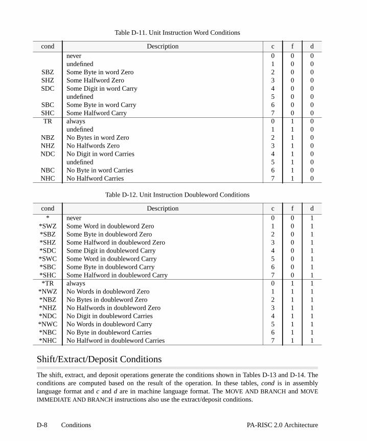
14. The
Shift/Extract/Deposit Conditions
The shift, extract, and deposit operations generate the conditions shown in Tables D-13 and D-conditions are computed based on the result of the operation. In these tables,cond is in assemblylanguage format andc andd are in machine language format. TheMOVE AND BRANCH andMOVEIMMEDIATE AND BRANCH instructions also use the extract/deposit conditions.
Table D-11. Unit Instruction Word Conditions
cond Description c f d
never 0 0 0undefined 1 0 0
SBZ Some Byte in word Zero 2 0 0SHZ Some Halfword Zero 3 0 0SDC Some Digit in word Carry 4 0 0
undefined 5 0 0SBC Some Byte in word Carry 6 0 0SHC Some Halfword Carry 7 0 0TR always 0 1 0
undefined 1 1 0NBZ No Bytes in word Zero 2 1 0NHZ No Halfwords Zero 3 1 0NDC No Digit in word Carries 4 1 0
undefined 5 1 0NBC No Byte in word Carries 6 1 0NHC No Halfword Carries 7 1 0
Table D-12. Unit Instruction Doubleword Conditions
cond Description c f d
* never 0 0 1*SWZ Some Word in doubleword Zero 1 0 1*SBZ Some Byte in doubleword Zero 2 0 1*SHZ Some Halfword in doubleword Zero 3 0 1*SDC Some Digit in doubleword Carry 4 0 1*SWC Some Word in doubleword Carry 5 0 1*SBC Some Byte in doubleword Carry 6 0 1*SHC Some Halfword in doubleword Carry 7 0 1*TR always 0 1 1
*NWZ No Words in doubleword Zero 1 1 1*NBZ No Bytes in doubleword Zero 2 1 1*NHZ No Halfwords in doubleword Zero 3 1 1*NDC No Digit in doubleword Carries 4 1 1*NWC No Words in doubleword Carry 5 1 1*NBC No Byte in doubleword Carries 6 1 1*NHC No Halfword in doubleword Carries 7 1 1
D-8 Conditions PA-RISC 2.0 Architecture

Branch On Bit Conditions
The branch on bit operations generate the conditions shown in Table D-15. In this table,cond is inassembly language format andc andd are in machine language format.
Table D-13. Shift/Extract/Deposit Word Instruction Conditions
cond Description c d
never 0 0= all bits in word are 0 1 0< leftmost bit in word is 1 2 0
OD rightmost bit is 1 3 0TR always 4 0<> some bits in word are 1 5 0>= leftmost bit of word is 0 6 0EV rightmost bit is 0 7 0
Table D-14. Shift/Extract/Deposit Doubleword Instruction Conditions
cond Description c d
* never 0 1*= all bits in doubleword are 0 1 1*< leftmost bit in doubleword is 1 2 1
*OD rightmost bit is 1 3 1*TR always 4 1*<> some bits in doubleword are 1 5 1*>= leftmost bit in doubleword is 0 6 1*EV rightmost bit is 0 7 1
Table D-15. Branch On Bit Instruction Conditions
cond Description c d
< leftmost bit in word is 1 0 0>= leftmost bit in word is 0 1 0*< leftmost bit in doubleword is 1 0 1
*>= leftmost bit in doubleword is 0 1 1
D-9PA-RISC 2.0 Architecture Conditions

D-10 Conditions PA-RISC 2.0 Architecture

s
” andcribe a
alue ofsed in
E Instruction Notation Control Structure
The control structures used in the instruction notation in Chapter 7, “Instruction DescriptionsChapter 9, “Floating-Point Instruction Set” are relatively standard. The expression statements descomputation performed by the ALU or some other hardware for its side effects rather than the vthe computation. The functions listed Table E-1 are used to localize long calculations that are useveral places.
Table E-1. Long Calculation Functions
Function Description
assemble_3(x) Assembles a 3-bit space register number:return(cat(x{2},x{0..1}))
assemble_6(x,y) Assembles a 6-bit extract/deposit length specifier:return(32 * x + 32 – y)
assemble_12(x,y) Assembles a 12-bit immediate:return(cat(y,x{10},x{0..9}))
assemble_16(x,y) Assembles a 16-bit immediate in one of two ways, depending on thePSW W-bit:
if (PSW[W])return(cat(y{13},xor(y{13},x{0}),xor(y{13},x{1}),y{0..12}))
elsereturn(cat(y{13},y{13},y{13},y{0..12}))
assemble_16a(x,y,z) Assembles a word-aligned 16-bit immediate in one of two ways,depending on the PSW W-bit:
if (PSW[W])return(cat(z,xor(z,x{0}),xor(z,x{1}),y,0{0..1}))
elsereturn(cat(z,z,z,y,0{0..1}))
assemble_17(x,y,z) Assembles a 17-bit immediate:return(cat(z,x,y{10},y{0..9}))
assemble_21(x) Assembles a 21-bit immediate:return(cat(x{20},x{9..19},x{5..6},x{0..4},x{7..8}))
assemble_22(a,b,c,d) Assembles a 22-bit immediate:return(cat(d,a,b,c{10},c{0..9}))
cat(x1, ..., xn) Concatenates the passed arguments,x1 throughxn.
low_sign_ext(x,len) Removes the rightmost bit ofx and extends the field to the left with thatbit to form a 64-bit quantity. The field is of sizelen:
return(sign_ext(cat(x{len-1},x{0..len-2}),len))
lshift(arg1,arg2) arg1 is logically shifted left by the number of bits specified inarg2. Thesize of the result is determined by the size ofarg1.
mem_load See “Memory Reference Instructions” on page 6-6.
E-1PA-RISC 2.0 Architecture Instruction Notation Control Structures

t of thent than
y
ng to
g toe
ly
edof
edof
Miscellaneous Constructs
Numerous mnemonic constructs are used to represent things that do not fit easily into the resnotation described in the previous table or whose details are more implementation-dependedefined. Table E-2 defines these constructs.
mem_store See “Memory Reference Instructions” on page 6-6.
rshift(arg1,arg2) arg1 is logically shifted right byarg2 bits. The size of the result isdetermined by the size ofarg1.
send_to_copr(u,t) Sends the 5-bit valuet to coprocessor unitu.
sign_ext(x,len) Extendsx on the left with sign bits to form a 64-bit quantity, taking theleftmost bit for the field of sizelen as the sign bit.
sign_ext_16(x,len) Extendsx on the left with sign bits to form a 16-bit quantity, taking theleftmost bit for the field of sizelen as the sign bit.
store_in_memory(space,offset,low,high,hint,data)
The function store_in_memory is identical to mem_store except that itforces the data to be stored into main memory. The data may optionallremain in the cache.
xor(x1, ..., xn) Produces the bitwise exclusive or of the passed arguments.
zero_ext(x,len) Extendsx on the left, for the field of sizelen, with zeros to form a 64-bitquantity.
Table E-2. Miscellaneous Constructs
Function Description
absolute_address(space,offset) Returns the absolute address correspondithe passed virtual address.
clear_BTS() Sets the valid bit in every entry of the BranchTarget Stack to 0.
coherence_index(space,offset) Returns the coherence index correspondinthe passed effective address. See “CachCoherence with I/O” on page F-11.
coherent_system Boolean; the value is 1 if the system is fulcoherent; the value is 0 if the system is partiallyor completely non-coherent.
coprocessor_condition(id,opcode,n) A coprocessor specific condition is returnbased on the arguments and the current state the coprocessor.
coprocessor_op(id,opcode,n,priv) A coprocessor specific operation is performbased on the arguments and the current state the coprocessor.
Table E-1. Long Calculation Functions (Continued)
Function Description
E-2 Instruction Notation Control Structures PA-RISC 2.0 Architecture

er
ssorsr
l
hen
s
e
see
ess
an
e
sd
tive
ess
DTLB_alloc(space,offset) Allocates a slot in the data TLB based on thspace and offset arguments, and returns a pointeto the slot.
DTLB_purge_broadcast(space,offset,page_size) In a multiprocessor system, the other proceare made to search their data TLBs for one omore entries which match the address rangespecified by space, offset, and page_size. Almatching entries are removed.
DTLB_purge_entries(space,offset) Removes one or more data TLB entries. Tentries to be removed are selected based osome implementation-dependent function of thearguments space and offset. No addresmatching is done. If there are entries whichwould match space and offset, these need not bamong the entries removed.
DTLB_purge_local(space,offset) Removes the specified TLB entry.
DTLB_search(space,offset) Searches the data TLB for a valid entry whovirtual address range encompasses the pagincluding the virtual address specified by spaceand offset, and returns a pointer to the slotcontaining the entry if one is found. If nomatching entry is found, NULL is returned.
Dcache_flush(space,offset) If the cache line containing the effective addris present, it is invalidated. If the line is dirty it iswritten back to main memory.
Dcache_flush_entries(space,offset) Zero or more cache lines specified by implementation-dependent function of theaddress are invalidated. If any of these lines ardirty, they are written back to main memory. Noaddress matching is done. If there are entriewhich would match space and offset, these neenot be among the entries invalidated.
Dcache_flush_or_purge(space,offset) If the cache line specified by the effecaddress is present, it is invalidated. If the line isdirty, it may optionally be written back tomemory.
Icache_flush(space,offset) If the cache line containing the effective addris present, it is invalidated. If the line is dirty, itis written back to main memory.
Table E-2. Miscellaneous Constructs (Continued)
Function Description
E-3PA-RISC 2.0 Architecture Instruction Notation Control Structures

an
e
s
e
is
at the
the
he
he
nce
ing
,
,
e
Icache_flush_entries(space,offset) Zero or more cache lines specified by implementation-dependent function of theaddress are invalidated. If any of these lines ardirty, they are written back to main memory(only possible in a combined cache.) No addresmatching is done. If there are entries whichwould match space and offset, these need not bamong the entries invalidated.
ITLB_alloc(space,offset) Same as DTLB_alloc except that a new slot allocated in the instruction TLB.
ITLB_purge_broadcast(space,offset,page_size) Same as DTLB_purge_broadcast except thinstruction TLB is purged.
ITLB_purge_entries(space,offset) Same as DTLB_purge_entries except that instruction TLB is purged.
ITLB_purge_local(space,offset) Same as DTLB_purge_local except that tinstruction TLB is purged.
ITLB_search(space,offset) Same as DTLB_search except that tinstruction TLB is searched.
measurement_enabled Boolean; when the value is 1, the performamonitor coprocessor is enabled to makemeasurements; when the value is 0, themeasurements are disabled. This condition isindependent of the state of CCR bit 2.
phys_mem_load(addr,low,high,hint) Returns the data in physical memory (consistof memory and the cache) starting at the low’thbit beyond the beginning of the byte at addressaddr, and ending at the high’th bit beyond thebeginning of the byte at address, addr. If thePSW E-bit is 1, the data bytes are swappedbefore they are returned. The cache control hinthint, is a recommendation to the processor onhow to resolve cache coherence. See “CachControl” on page 6-9. This function is used forabsolute accesses to memory.
Table E-2. Miscellaneous Constructs (Continued)
Function Description
E-4 Instruction Notation Control Structures PA-RISC 2.0 Architecture
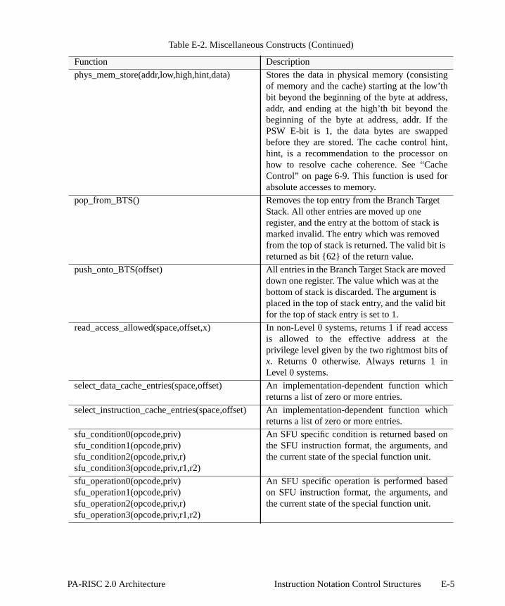
ting
,
,
e
d
cess
hich
hich
phys_mem_store(addr,low,high,hint,data) Stores the data in physical memory (consisof memory and the cache) starting at the low’thbit beyond the beginning of the byte at addressaddr, and ending at the high’th bit beyond thebeginning of the byte at address, addr. If thePSW E-bit is 1, the data bytes are swappedbefore they are stored. The cache control hinthint, is a recommendation to the processor onhow to resolve cache coherence. See “CachControl” on page 6-9. This function is used forabsolute accesses to memory.
pop_from_BTS() Removes the top entry from the Branch TargetStack. All other entries are moved up oneregister, and the entry at the bottom of stack ismarked invalid. The entry which was removedfrom the top of stack is returned. The valid bit isreturned as bit {62} of the return value.
push_onto_BTS(offset) All entries in the Branch Target Stack are movedown one register. The value which was at thebottom of stack is discarded. The argument isplaced in the top of stack entry, and the valid bitfor the top of stack entry is set to 1.
read_access_allowed(space,offset,x) In non-Level 0 systems, returns 1 if read acis allowed to the effective address at theprivilege level given by the two rightmost bits ofx. Returns 0 otherwise. Always returns 1 inLevel 0 systems.
select_data_cache_entries(space,offset) An implementation-dependent function wreturns a list of zero or more entries.
select_instruction_cache_entries(space,offset) An implementation-dependent function wreturns a list of zero or more entries.
sfu_condition0(opcode,priv)sfu_condition1(opcode,priv)sfu_condition2(opcode,priv,r)sfu_condition3(opcode,priv,r1,r2)
An SFU specific condition is returned based onthe SFU instruction format, the arguments, andthe current state of the special function unit.
sfu_operation0(opcode,priv)sfu_operation1(opcode,priv)sfu_operation2(opcode,priv,r)sfu_operation3(opcode,priv,r1,r2)
An SFU specific operation is performed basedon SFU instruction format, the arguments, andthe current state of the special function unit.
Table E-2. Miscellaneous Constructs (Continued)
Function Description
E-5PA-RISC 2.0 Architecture Instruction Notation Control Structures

ld ofs
ing
,
e
.
space_select(s_field,base,format) Returns the space ID selected by the s-fiethe instruction and the base register value afollows:
if (PSW[W])if (format == LONG_DISP)
return(SR[base{0..1} + 4]);else /* short or indexed */
if (s_field == 0)return(SR[base{0..1} + 4]);
else if (priv == 0)return(SR[s_field]);
elseundefined;
else /* PSW[W] == 0 */if (s_field == 0)
return(SR[base{32..33} + 4]);else
return(SR[s_field]);
virt_mem_load(space,offset,low,high,hint) Returns the data in virtual memory (consistof memory and the cache) starting at the low’thbit beyond the beginning of the byte at addressspace,offset and ending at the high’th bit beyondthe beginning of the byte at address,space,offset. If the PSW E-bit is 1, the data bytesare swapped before they are returned. The cachcontrol hint, hint, is a recommendation to theprocessor on how to resolve cache coherenceSee “Cache Control” on page 6-9. This functionis used for virtual accesses to memory.
Table E-2. Miscellaneous Constructs (Continued)
Function Description
E-6 Instruction Notation Control Structures PA-RISC 2.0 Architecture

g of
,
e
.
ess
virt_mem_store(space,offset,low,high,hint,data) Stores the data in virtual memory (consistinmemory and the cache) starting at the low’th bitbeyond the beginning of the byte at addressspace,offset and ending at the high’th bit beyondthe beginning of the byte at address,space,offset. If the PSW E-bit is 1, the data bytesare swapped before they are stored. The cachcontrol hint, hint, is a recommendation to theprocessor on how to resolve cache coherenceSee “Cache Control” on page 6-9. This functionis used for virtual accesses to memory.
write_access_allowed(space,offset,x) In non-Level 0 systems, returns 1 if write accis allowed to the effective address at theprivilege level given by the two rightmost bits ofx. Returns 0 otherwise. Always returns 1 inLevel 0 systems.
Table E-2. Miscellaneous Constructs (Continued)
Function Description
E-7PA-RISC 2.0 Architecture Instruction Notation Control Structures

E-8 Instruction Notation Control Structures PA-RISC 2.0 Architecture

l
asidee TLBents of
ddresserency
escribe
isiblections,
.
be
ofto
DTLB.irtualsize may
the
thear the
y not, in
F TLB and Cache Contro
This appendix provides detailed information relating to operation of the TLB (Translation LookBuffer) and cache in a PA-RISC system. It describes how software can control the contents of thunder various conditions such as TLB miss handling and also specifies the operation requiremthe TLB.
The appendix also describes the responsibilities of system software in regards to handling aaliasing as well as cache move-in rules. Finally, a brief summary of the guidelines relating to cohin multiprocessor systems is provided.
TLB Control
TLBs function as buffers for the most frequently used address translations. Terms used to dTLBs are given below.
Entry The term entry refers to a translation which is present in the TLB. Entries are vto software through references (such as load, store, and semaphore instruaccess rights probes, and theLOAD PHYSICAL ADDRESS instruction).
Slot Hardware resources in the TLB which hold entries are referred to as slots.
Remove An entry is removed when some action causes it to be inaccessible to software
Insertion of translations into the TLB, for example, causes other entries toremoved. Entries can be explicitly removed by purging them.
NOTEFrom a hardware perspective, a translation is removed when it is displaced by the insertionanother translation. If each slot has an associated valid bit which causes that slot not participate in TLB lookup, then a translation is removed if the slot that contains it is markedinvalid. This would be one way of implementing TLB purges.
Several mechanisms can be used by software to remove a specific translation from the ITLB or First, when a new translation is inserted into the TLB, any old translations which overlap the vaddress range of the new translation are removed. Second, a specific virtual address and page be used to purge (remove) the associated translations from the TLB. ThePURGE INSTRUCTION TLBandPURGE DATA TLB instructions perform this function. These instructions also optionally causetranslation to be removed from the TLBs of other processors in a multiprocessor system.
Translations may also be removed from the TLB using thePURGE INSTRUCTION TLB ENTRY and thePURGE DATA TLB ENTRY instructions. These purge some machine-specific number of entries inTLB without regard for the translation. These instructions are used by system software to cleentire instruction or data TLB.
Because the TLB is managed by a mixture of hardware and software mechanisms, software ma
F-1PA-RISC 2.0 Architecture TLB and Cache Control

e TLBever, inmakere is
These
B miss
t the
to the
. The
to the
pply:
. The
to the
general, rely on the existence of translations in the TLB and hardware may, in general, removentries at any time, provided that forward progress is assured. There are limited situations, howwhich software may rely on a translation existing in the TLB. This means that software may virtual accesses using this relied-upon translation, and no TLB miss fault will occur. Hardwarequired to retain this TLB entry as long as the constraints of the limited situation are met. situations are described in “TLB Operation Requirements” on page F-3.
NOTEAs a result, the following hardware actions are allowed, except in the defined limitedsituations.
• A TLB miss fault may be taken even though the translation exists in the TLB.
• In the event of a TLB error, one or more entries may be removed.
Note also that software may not rely on the existence of any translations in the TLBimmediately after any group 1, 2, or 4 interruption.
Software TLB Miss Handling
In order to insure forward progress, some restrictions are placed on software which performs TLhandling.
For instruction TLB miss handling, the following restrictions apply:
• Software can insert multiple instruction address translations into the ITLB, provided thatranslation which caused the trap is inserted last.
• Software must not execute a purge TLB instruction using the virtual address correspondingdata address translation needed for the execution of the trapping instruction.
• Software must not insert translations into the DTLB.
For non-access instruction TLB miss handling, the following restrictions apply:
• Software can only insert into the ITLB up to all of the eight translations for the page grouptranslation which caused the trap must be inserted last.
• Software must not execute a purge TLB instruction using the virtual address correspondingdata address translation needed for the execution of the trapping instruction.
• Software must not insert translations into the DTLB.
For data TLB miss handling and non-access data TLB miss handling, the following restrictions a
• Software can only insert into the DTLB up to all of the eight translations for the page grouptranslation which caused the trap must be inserted last.
• Software must not execute a purge TLB instruction using the virtual address correspondinginstruction address translation needed for the execution of the trapping instruction.
The following restrictions apply to all four TLB miss handlers:
F-2 TLB and Cache Control PA-RISC 2.0 Architecture

howler, if
ded asords in
es an
. Thelation
ng the
slation
r onlowing
relied-
llified, to the
• Software must not make any virtual references.
• Software must not execute anyPURGE DATA TLB ENTRY or PURGE INSTRUCTION TLB ENTRYinstructions.
Hardware TLB Miss Handling
The default endian bit (see “Byte Ordering (Big Endian/Little Endian)” on page 2-19) determinesdata from the hardware-visible page table is interpreted by the hardware TLB miss handimplemented. If the default endian bit is 0, the hardware-visible page table entries are loadoublewords in big-endian format; if the default endian bit is 1, the entries are loaded as doublewlittle-endian format.
If a data prefetch instruction (described in “Data Prefetch Instructions” on page 6-11) referencaddress which misses in the data TLB, the hardware TLB miss handler should not be invoked.
TLB Operation Requirements
Software may rely on the existence of particular translations in the TLB only in certain situationsfollowing describes the situations in which software may rely upon the fact that a specific transwill continue to exist in the TLB. In these situations, software may make virtual accesses usirelied-upon translation, and no TLB miss fault will occur (including non-access TLB miss faults).
1. When an instruction takes one of the following interruptions, the associated data address tranwill remain in the DTLB, and is termed the relied-upon translation.
The translation will continue to remain in the DTLB, meaning no data TLB miss fault will occuvirtual data accesses which use this translation, for as long as software meets the folconstraints:
• No virtual data references are made to pages other than the page corresponding to theupon translation.
• The execution stream does not contain nullified instructions which, had they not been nuwould have made virtual data references to pages other than the page correspondingrelied-upon translation.
• No memory management instructions other thanLPA are executed. (See “Memory
Intr. No. Interruption
18 data memory protection/unaligned data reference trap19 data memory break trap20 TLB dirty bit trap21 page reference trap22 assist emulation trap26 data memory access rights trap27 data memory protection ID trap28 unaligned data reference trap
F-3PA-RISC 2.0 Architecture TLB and Cache Control

ent
d by
ual
of
misstware
it,
s, or
irtual
” for a
d by
Management Instructions (Mem_Mgmt)” on page C-5 for a list of memory manageminstructions.)
• No purge TLB instructions which would purge the relied-upon translation are executeother processors in a multiprocessor system.
• No virtual instruction references are made.
• No DIAGNOSE instructions are executed.
• No attempt is made to execute undefined instructions.
Programming NoteSoftware may rely upon this translation in order to improve performance in handling theabove-mentioned traps. For example, the absolute address which corresponds to the virtaddress used in the trapping instruction can be determined by using this code sequence:
LPA x(s,b),t
Because no TLB miss fault can occur, the interruption handler need not incur the overhead making itself interruptible.
2. If the PSW Q-bit is 1, and is set to 0 by aRESET SYSTEM MASK or MOVE TO SYSTEM MASKinstruction, the instruction address translation used to fetch theRSM or MTSM instruction willcontinue to remain in the ITLB, and is termed the relied-upon translation. No instruction TLBfault will occur on virtual instruction accesses which use this translation for as long as sofmeets the following constraints:
• TheRSM or MTSM instruction which sets the PSW Q-bit to 0 (the clearingRSM or MTSM) ispreceded by anotherRSM, SSM, or MTSM instruction which does not affect the PSW Q-band which appears at least 8 instructions prior.
• The instructions between the initialRSM, SSM, or MTSM instruction and the clearingRSM orMTSM do not include any memory management instructions, virtual data referenceinstruction references to pages other than the code page containing the clearingRSM or MTSMinstruction.
• The clearingRSM or MTSM instruction is not within 8 instructions of a page boundary.
• No virtual data references are made.
• The execution stream does not contain nullified instructions which would have made vdata references had they not been nullified.
• No FLUSH INSTRUCTION CACHE instructions are executed with the PSW D-bit equal to 1.
• No memory management instructions are executed. (See Appendix C, “Operation Codeslist of memory management instructions.)
• No purge TLB instructions which would purge the relied-upon translation are executeother processors in a multiprocessor system.
F-4 TLB and Cache Control PA-RISC 2.0 Architecture

clearing
on, ae
s
ofis
-bit
nsibility
te and ais said toote thateed not
• No instruction references are made to pages other than the code page containing the RSM or MTSM instruction.
• No DIAGNOSE instructions are executed.
• No undefined instructions are attempted to be executed.
• No instructions are executed which are followed, within 8 words, by a branch instructimemory management instruction, aDIAGNOSE instruction, an undefined instruction, or a pagboundary.
Programming NoteSoftware may rely upon this instruction translation in order to improve performance in procesdispatch. For example, in this code sequence:
SSM 0,gr0 ; initial RSM, SSM or MTSMLDW ; set up process state. ; must be at least 7 instructions. ; between the system mask instructions.LDWRSM 8,gr0 ; set PSW Q-bit to 0MTCTL reg1,cr20; set up IIASQMTCTL reg2,cr20MTCTL reg3,cr21; set up IIAOQMTCTL reg4,cr21LDW ; set up last of process state...LDWRFI ; dispatch process
Because no TLB miss fault can occur, the interruption handler need not incur the overhead disabling code translation just prior to process dispatch. Note that the LDW instructions in thsequence must use absolute addresses. (Use absolute loads, or do these with the PSW Dequal to 0.)
Address Aliasing
Normally, a virtual address does not translate to two different absolute addresses. It is the respoof memory management software to avoid the ambiguity such occurrences would create.
Caches are required to permit a physical memory location to be accessed by both an absoluvirtual address when the virtual address is equal to the absolute address. Such a virtual address be equivalently-mapped. For equivalently-mapped addresses in the memory address space, nsince the upper 2 bits of the offset are not used in forming the absolute address, these bits n
F-5PA-RISC 2.0 Architecture TLB and Cache Control
is being
d 47.
space
gh
s,ays
eal
ses ares
ere
lly non-
match the corresponding bits in the virtual address for the two addresses to be equivalently-mapped.
The instruction and data caches are required to detect that the same physical memory location accessed by two virtual addresses that satisfy all the following requirements:
1. The two virtual addresses map to the same absolute address.
2. Offset bits 44 through 63 are the same in both virtual addresses.
3. If the use of space bits in generating the cache index is enabled, the two virtual addresses have thesame values for the following space identifier bits: 36, 37, 38, 39, 40, 41, 42, 43, 44, 45, 46, an
Processors must provide an implementation-dependent mechanism to enable/disable the use of bits in generating the cache index.
NOTEImplementations are encouraged to provide a mechanism to enable/disable the threecontiguous groups of 4 space bits (bits 36 through 39, bits 40 through 43, and bits 44 throu47) independently.
When space bits are enabled for use in generating the cache index, for each space bit that participatethe corresponding offset bit which gets ORed with it in the generation of virtual addresses is alwforced by hardware to 0 for address generation purposes.
These rules provide offset aliasing on 16 Mbyte boundaries, with optional support for offset aliasing onsmaller power of two sized boundaries, and either restricted or unlimited space aliasing.
Two virtual addresses that satisfy all of the above requirements are called equivalent aliases of eachother. Virtual addresses that satisfy rule 1 but violate rule 2 or 3 are non-equivalent aliases, and are morrestricted in their use. For non-equivalent aliases, read-only aliasing is supported with minimrestrictions, and many-reader/one-writer aliasing is supported with more significant restrictions.
Generally, if system software must use multiple addresses for the same data, these addresequivalent aliases (or are an absolute address and an equivalently-mapped virtual address). Thidescription of non-equivalent aliasing, and the restrictions on software only apply in rare situationswhen non-equivalent aliasing is necessary.
For the purposes of supporting non-equivalent aliasing, a read-only translation is defined as one whthe TLB and page table both meet at least one of the following conditions:
• The page type in the access rights field is 0, 2, 4, 5, 6, or 7. (See “Access Control” on page3-11.)
• The D-bit (dirty bit) is 0.
A translation not meeting this requirement is termed a write-capable translation.
Software is allowed to have any number of read-only non-equivalently aliased translations to a physicapage, as long as there are no other translations to the page. This is referred to as read-onequivalent aliasing.
Before a write-capable translation is enabled, all non-equivalently-aliased translations must be removed
F-6 TLB and Cache Control PA-RISC 2.0 Architecture
d at this Beforege (the
he pagenabledslationquired ifas many-
ed read-ny write-flush the
lentlyachine
es. It isabove.
ccess by
s by its
cess by
h-
atlyl
py
s. Twobsolute
from the page table and purged from the TLB. (Note that the caches are not required to be flushetime.) The write-capable translation may then be used to read and/or modify data on that page.any non-equivalent aliased translation is re-enabled, the virtual address range for the writable paentire page) must be flushed from the cache, and the write-capable translation removed from ttable and purged from the TLB. If an old read-only translation is re-enabled, or a translation is ethat is equivalently-aliased to an old translation, the virtual address range for the re-enabled tranmust be flushed from the cache before accesses are made to the page. (This flushing is only rethe re-enabled virtual page has not been flushed since it was last accessed.) This is referred to reader/one-writer non-equivalent aliasing.
Absolute read accesses can be made to a page which is mapped with a non-equivalently-mapponly translation, as long as the absolute address range accessed is flushed before enabling acapable translation. Since absolute accesses do not cause prefetching, it is not necessary to entire page - only the accessed range need be flushed.
All other uses of non-equivalent aliasing (including simultaneously enabling multiple non-equivaaliased translations where one or more allow for write access) are prohibited, and can cause mchecks or silent data corruption, including data corruption of unrelated memory on unrelated pagthe responsibility of privileged software to avoid non-equivalent aliasing, except as described This requires flushing the affected address range from the caches prior to any of the following:
• Changing the address mapping in the TLBs.
• Making an absolute access to a location which might reside in the caches as a result of an aa virtual address that was not equivalently mapped.
• Making a virtual access to a location which might reside in the caches as a result of an accesabsolute address that was not equivalently mapped.
• Making a virtual access to a location which may reside in the caches as a result of an acanother virtual address that was not equivalently aliased.
NOTEThe restrictions on non-equivalent aliases are necessary to allow the design of higperformance caches and memory interconnect, including multi-level caches (including victimor miss caches) and directory-based coherency structures. Coherency schemes are gresimplified by allowing the assumption that there is at most a single private copy of a physicaline at any time. The read-only translation informs hardware to request a shared or public coof the line.
Cache Move-in Restrictions
Data and instructions from memory can be brought into cache only under certain circumstancedifferent schemes are used for controlling cacheability – one for virtual accesses and one for aaccesses.
F-7PA-RISC 2.0 Architecture TLB and Cache Control

ly, if anto theove-in.es, but
R-bittrolling
lly, onlyefinition
y cause
t not as
as data, in “Data
hethernce is spaces,erences
ddress
(access
pt wherellowing
listed
Virtual Accesses
For virtual accesses, cache move-in is controlled by a mapping-based approach. Generaltranslation exists in the TLB that permits access, the memory on that page may be brought icache. The access information in the TLB entry must meet a simple check, however, to permit mThis is required in order to allow for translations which can be used for cache flushing purposwhich do not enable move-in. This is described in detail in following sections.
Since TLB miss handling may insert into the TLB any entry in the page table for which the (Reference bit) is 1, system software should consider the page table as the main tool for concacheability of memory.
Absolute Accesses
For absolute accesses, cache move-in is controlled by a reference-based approach. Generainstructions and data referenced by executed instructions may be brought into the cache. The dof “reference” is somewhat loose to permit instruction prefetching and instruction pipelining.
No data reference may cause a move-in to the instruction cache and no instruction reference maa move-in to the data cache. This means that the execution of aFLUSH DATA CACHE or PURGE DATACACHE instruction guarantees that the addressed line, if it has been referenced as data buinstructions, is no longer present in the cache system. Similarly, only aFLUSH INSTRUCTION CACHEinstruction is required to guarantee that a line which has been referenced as instructions but notis no longer present in the cache system. The actions which constitute a reference are describedCache Move-In” on page F-8 and “Instruction Cache Move-In” on page F-9.
If implemented, the U (Uncacheable) bit is found in the data TLB entry associated with a page. Wor not the U-bit is implemented, the state of this bit if implemented, whether the memory referevirtual or absolute, and whether the reference is made from a page in the memory or I/O addressdetermine if the reference may be moved into the data cache. The detailed rules for moving refinto the data cache are specified in “Data Cache Move-In” on page F-8.
Data Cache Move-In
For virtual accesses, cache move-in is permitted only if there is a translation for the virtual awhich meets both of these conditions:
• The page type field in the access rights for the entry contains a value in the range 0 to 3 rights allow read access).
• The T-bit in the entry is 0.
For absolute accesses, data lines are brought into the cache only as a result of references. Excenoted, a data reference may move in all of the lines on the page containing the reference. The foactions constitute a data reference, and may cause move-in to the data cache:
• Execution of a load, store, or semaphore instruction
• Interruption of a load, store, or semaphore instruction by any interruption except the ones
F-8 TLB and Cache Control PA-RISC 2.0 Architecture

ch
priortaken
ion are
nceons can
ddress
(access
ach X
ata andy moveuential
to the
aining
ch to be
by an
below:
NOTEBecause protection is checked (interruption 10), the reference cannot bring in any data whicould not have been accessed.
• A load or store instruction which is left at the front of the interruption queues because of ainstruction which took a group 4 interruption, provided that the load or store would not have any of the above interruptions (6, 7, 8, 10).
Data items which would have been referenced by a nullified load, store, or semaphore instructnot moved in.
The instructionsLDWA, LDDA, STWA, and STDAare exceptions to the general rule that a data referemay cause all of the lines in the page containing the reference to be moved in. These instructicause only the referenced line to be moved into the data cache.
Instruction Cache Move-In
For virtual accesses, cache move-in is permitted only if there is a translation for the virtual awhich meets both of these conditions:
• The page type field in the access rights for the entry contains a value in the range 2 to 7 rights allow execute access).
• The access rights for the entry does not match this binary pattern: “111 0X 1X”, where estands for either a 1 or a 0 (execute-only page where PL2≤ PL ≤ PL1 but PL2 > PL1).
For absolute accesses, instructions are brought into the instruction cache, or combined dinstruction cache, only as a result of references. Except where noted, an instruction reference main all of the lines on the page containing the reference, as well as all of the lines on the next seqpage. The following actions constitute an instruction reference, and may cause move-in instruction cache:
• Execution of an instruction
• Execution of a nullified instruction. This action can cause only those lines on the page contthe instruction to be moved in
• Execution of a branch can cause all of the lines on the page containing the target of the branmoved in.
• Execution of a branch to a target instruction which is the last instruction on a page, followed
Intr. No. Interruption
6 instruction TLB miss fault7 instruction memory protection trap8 illegal instruction trap10 privileged operation trap
F-9PA-RISC 2.0 Architecture TLB and Cache Control

taining
page
in.
geustthe
sses that
to bemove-in
s to that the new
ubsequent system, another
line has
es not
ry
y othered (for
instruction which traps (in the branch delay slot), can cause all of the lines on the page conthe target instruction, as well as all of the lines on the next sequential page to be moved in.
• Interruption of an instruction by any interruption
• A branch instruction which takes a group 4 interruption can cause all of the lines on thecontaining the instruction which would have been branched to, to be moved in.
Instructions which would have been branched to by nullified or untaken branches are not moved
Programming NoteIf a data page immediately follows an instruction page, it is possible that the entire data pamay have been moved into the instruction cache because of these move-in rules. Software mbe aware of this fact and flush both the instruction and the data caches in order to remove data page from the cache.
I/O Addresses and Uncacheable Memory
Accesses to the I/O address space, whether through absolute accesses or through virtual accemap to the I/O address space, are never cached.
Virtual accesses for which the U-bit in the TLB entry is 1 are not cached.
Cache Flushing
Cache control instructions have two effects on caching. One is that they force particular linesremoved from the cache. The other is that, for absolute accesses, they disable further cache from the affected memory range until further references to that range are made.
For virtual accesses, a purge TLB instruction stops (disables) any subsequent move-in operationpage. Subsequent accesses must trigger a TLB miss, and then may move into the cache only iftranslation from the page table allows it.
For absolute accesses, a flush cache or purge cache instruction to a page stops (disables) any smove-in operations to that page until another reference to that page is made. In a multiprocessorthese instructions stop any subsequent move-in operations to that page on all processors untilreference to that page is made.
Once a line could have been brought into a cache, the only way software can insure that the been removed from the cache is to
• Purge the translation from the TLB and insure that the corresponding page table entry doallow cache move-in (if the cached memory was brought in due to a virtual access), and
• Flush or purge the line and execute aSYNC instruction, or flush the entire cache with flush-entinstructions and execute aSYNC instruction.
Once a line has been made cacheable, even if it is subsequently forced out of the cache baccesses, the cache system can move it in again at will, until the enabling translation is removvirtual accesses) or until the line is flushed (for absolute accesses).
F-10 TLB and Cache Control PA-RISC 2.0 Architecture

om then:
1 (this
ents D- move-
or data
eneralata it is that,
he by the
rent I/Ooherentn wheret writees in
ushing
cessor
t (e.g.,
condary
cachehe I/O
System software can create translations which allow a virtual address range to be flushed frcaches, but which do not enable cache move-in. There are two ways of creating such a translatio
• Create a translation in which the page type field in the access rights has the value 0 or prevents I-cache move-in), and has the T-bit 1 (this prevents D-cache move-in), or
• Create a translation in which the page type field in the access rights has the value 7 (this prevcache move-in), and has the special access rights pattern “111 0X 1X” (this prevents I-cachein).
Cache Coherence with I/O
Accesses to memory by I/O modules may be either coherent or non-coherent with processcaches.
Coherent I/O
Processors in systems with coherent I/O modules must implement theLOAD COHERENCE INDEXinstruction, which loads the coherence index corresponding to a given virtual address into a gRegister. Coherent I/O modules provide the coherence index along with the absolute address of dreading from or writing to memory. The coherence index must provide enough information suchtogether with the absolute address, the processor can find data that was brought into its data cacoriginal virtual address.
Software need not flush or purge data from the data cache when sharing the data with a cohemodule. For I/O output (e.g., memory to secondary storage), the coherent I/O module performs cread operations which will read the data from memory or a processor’s data cache depending othe most up-to-date copy is located. For I/O input, the coherent I/O module performs coherenoperations which will write the data to memory and also update or invalidate matching linprocessor data caches.
Coherent I/O operations are not coherent with instruction caches. Software is responsible for flthe appropriate instruction cache lines before or after the I/O operation.
Non-coherent I/O
Non-coherent I/O modules process data in memory; this data can be non-coherent with procaches. Software is required to insure that:
1. The contents of the appropriate caches are flushed to main memory prior to an I/O outpumemory to secondary storage) operation.
2. The contents of the appropriate caches are purged or flushed prior to an I/O input (e.g., sestorage to memory) operation.
3. The contents of the appropriate caches are purged following an I/O input operation, if themove-in rules would have allowed the processor to move the data into the cache during toperation.
F-11PA-RISC 2.0 Architecture TLB and Cache Control

tionally,pace for
ce.
space forpt that device.
ically arrogate
flushescations
ith theis design
must be since the that was if it was
in order
ecks.
truction
in anatingts, localther
Operations Defined for I/O Address Space
Semaphore instructions are undefined if the address maps to the I/O address space. Addisemaphore instructions are undefined if the address maps to a page in the memory address swhich the TLB U-bit is 1.
Cache flush and purge instructions execute as NOPs if the address maps to the I/O address spa
Data prefetch instructions directed to the I/O address space or to a page in the memory address which the TLB U-bit is 1 behave as described in “Data Prefetch Instructions” on page 6-11 excethey must not affect the cache state and may optionally generate a transaction to the addressed
All accesses other than those listed above are defined to the I/O address space.
Cache and TLB Coherence in Multiprocessor Systems
Multiprocessor systems may include PA-RISC processors as well as other processors.
The cache-coherent part of a multiprocessor system is required to behave as if there were logsingle D-cache and a single I-cache. If there are multiple physical D-caches, they must cross-intefor current data and must broadcast purge and flush operations except forFDCE andFICE. Purge andflush operations do not cause TLB faults on other processors. Multiple I-caches require only that be broadcast. The I-cache is read-only, and software is responsible for coherence when modifiare made to the instruction stream.
The non-cache-coherent part of a multiprocessor system (if any) may either cross-interrogate wcaches in the cache-coherent part of the system, or may have an independent cache system. Thdecision is generally based on the frequency of data sharing.
In the cache-coherent part of a multiprocessor system, all data references to cacheable pagessatisfied by data that was obtained using cache coherence checks, and has remained coherentdata was moved in. Data references to uncacheable pages do not need to be satisfied by dataobtained using cache coherence checks. Data from an uncacheable page could be in a cachemoved in when that page was marked cacheable, but the page is now marked uncacheable.
Implementations with write buffers must also check buffer contents on cache coherence checks, to insure proper ordering of storage accesses.
Instruction references need not be satisfied by data that was obtained using cache coherence ch
Instruction caches are read-only. In the case of a separate instruction cache implementation, inscache lines must never be written back to main memory.
Each processor in a multiprocessor system must have its own TLB system. All TLBs multiprocessor system are required to broadcast global purges to all other TLBs. The origiprocessor’s purge instruction suspends until all target processors complete the purge. TLB inserpurges and thePDTLBE andPITLBE instructions are not broadcast and do not affect translation on oprocessors.
F-12 TLB and Cache Control PA-RISC 2.0 Architecture

l
ted bytion is
lly. For-wordtire old
yo executeor may
aphoreom thet order
ssor A
ves that
ocessor
referredonsidered
G Memory Ordering Mode
This appendix begins with a description of the memory ordering model that must be implemenPA-RISC systems to ensure proper operation in multiprocessor systems. The informal descripfollowed by a formal model which describes the behavior of any correct implementation.
Atomicity of Storage Accesses
All load, store, and semaphore instructions (with one exception below) access storage atomicaexample, a double-word load instruction executing on one processor concurrently with a doublestore instruction to the same address executing on another processor will receive either the envalue or the entire new value.
The STORE BYTES and STORE DOUBLEWORD BYTESinstructions, when referencing the memoraddress space are atomic, but when referencing the I/O address space, are not guaranteed tatomically. Doubleword load and store instructions which reference the I/O address space may not be atomic, depending on the capabilities of the bus.
Ordering of References
References to the address space (both to memory and I/O) through load, store, and seminstructions always appear to the executing processor to be done in program order. However, frviewpoint of a second processor in a multiprocessor system or from an I/O module, the apparenof memory references may be different in certain situations.
Ordering Definitions
A processor (or I/O module) A is said to have observed a store by another processor B if proceexecutes a load instruction and receives the value stored by processor B.
A store is said to be performed by a processor when another processor or I/O module obserstore.
A load is said to be performed by a processor A if there are no unobserved stores from any prthat could affect the value of that load.
References to the address space through load, store, semaphore, and TLB purge instructions areto as accesses. Cache flush and purge operations are discussed separately and are not caccesses. All accesses can be classified as either strongly ordered, ordered, or weakly ordered.
The following accesses are termed strongly ordered:
• Accesses to the I/O address space.
• Accesses to any page for which the TLB U-bit is 1.
• The semaphore instructions (LDCW, LDCD).
G-1PA-RISC 2.0 Architecture Memory Ordering Model

-bit is
esses areed.
y order,ads and
thesequence
r must,ormed
rved byctions
o
• TheSYNC instruction forces ordering as though it were a strongly ordered access.
• The TLB purge instructions (PITLB, PDTLB).
The following accesses are termedordered:
• Certain loads and stores, when used with a special ordered completer,O.
• Virtual accesses made when the PSW[O] bit is 1, to an address in a page for which the TLB O1.
• Absolute accesses made when the PSW[O] bit is 1.
Accesses which are neither strongly ordered nor ordered are termedweakly ordered.
Ordering Requirements
An access which is strongly ordered is guaranteed to be performed before any subsequent accperformed and is guaranteed not to be performed until after all prior accesses have been perform
An ordered load is guaranteed to be performed before any subsequent accesses are performed.
All prior accesses are guaranteed to be performed before an ordered store is performed.
An ordered store is guaranteed to be performed before any subsequent ordered load.
Weakly ordered accesses may appear to another processor or I/O module to be performed in anprovided that they meet the constraints of other strongly ordered accesses and of other ordered loordered stores.
The effect of these ordering constraints is transitive. That is,
if a sequence of memory accesses initiated by a first processor must, according torules, be observed by a second processor to have been performed prior to a seof memory accesses initiated by this second processor,
and if the same sequence of memory accesses initiated by the second processoaccording to these rules, be observed by a third processor to have been perfprior to a sequence of memory accesses initiated by this third processor,
then the sequence of memory accesses initiated by the first processor must be obsethe third processor to have been performed prior to the sequence of transainitiated by the third processor.
NOTEAn example of the observability of the ordering of accesses can be seen by considering twprocesses, A and B, running concurrently on a multiprocessor system.
process A process B
load x load y
store y store x
G-2 Memory Ordering Model PA-RISC 2.0 Architecture

cess
, and aever, on
ses to
peration
rations.
pending,nstraints,
sses to
s of any
essary.efore
by the
re must
If process B observes A’s store to y, and the references to y are ordered accesses, then proB may rely on the fact that its store to x will not affect the value seen by process A.
Cache flush operations are weakly ordered. Flush operations may be delayed or held pendingsequence of flush operations may be executed in any order. There are some constraints, howtheir ordering:
• A flush data cache operation is guaranteed not to be performed until after all prior accesaddresses within the same cache line have been performed.
• A flush data cache operation is guaranteed to be performed before any subsequent purge oto the same cache line, to prevent loss of data.
If a combined cache is implemented, these same constraints apply to flush instruction cache ope
Cache purge operations are weakly ordered. Cache purge operations may be delayed or held and a sequence of cache purge operations may be executed in any order. There are some cohowever, on their ordering:
• A purge data cache operation is guaranteed not to be performed until after all prior acceaddresses within the same cache line have been performed.
• A purge data cache operation is guaranteed to be performed before any subsequent accesaddress within the same cache line, to prevent loss of data.
TheSYNC instruction is used to ensure ordering of cache flush and purge operations, when necAfter executing aSYNC instruction, any pending flush and purge operations are completed bperforming any subsequent load, store, semaphore, flush, or purge instructions.
The SYNC instruction enforces the ordering of only those flush and purge operations caused instructions executed on the same processor which executes theSYNC instruction.
In multiprocessor systems, to allow non-privileged code to do cache management, system softwaexecute aSYNC instruction when switching processes.
G-3PA-RISC 2.0 Architecture Memory Ordering Model

use.
gram
rupts
a dataly been.
Programming NoteIt is important to be aware of the delayed nature of cache flush and purge operations, and to SYNC instructions to force completion where necessary. The following example illustrates this
Consider two processes sharing a memory locationx which is protected by a semaphores.
In the absence of the SYNC instruction, it would be possible for process B’s store tox tocomplete before the purge ofx is completed (since the purge may have been delayed). Thepurge ofx could then destroy the new value.
MTCTL and MFCTL instructions involving the EIR and the EIEM must appear to preserve proorder.
Interrupts must be masked immediately following a MTCTL to the EIEM register that masks interor an RSM or MTSM that sets the PSW I-bit to 0.
Modification of resources which affect data access take effect immediately. Acknowledgment of TLB purge request from another processor must not be made until after the purge has logicalperformed. Data access resources include Protection Identifier Registers, PSW, and TLB entries
process A on Processor 1 process B on Processor 2 note
LDCW s A acquires semaphore
PDC x A executes purge
SYNC Force completion of purge
STW s A releases semaphore
LDCW s B acquires semaphore
STW x
G-4 Memory Ordering Model PA-RISC 2.0 Architecture

program
rces
ed to an
operationd, thenn cache
perationlly anyt purge
The following table summarizes these ordering requirements.
Sequences marked with O must appear to other processors and I/O modules to be performed in order.
Notes:
1. The SYNC instruction is different from other strongly ordered accesses in that it also foordering with respect to cache flush and purge operations.
2. A purge operation is guaranteed to be performed before any subsequent access is performaddress within the same cache line.
3. Any access is guaranteed to be performed before a subsequent flush data cache or purge is performed to an address within the same cache line. If a combined cache is implementeadditionally any access is guaranteed to be performed before a subsequent flush instructiooperation is performed to an address within the same cache line.
4. Any flush data cache operation is guaranteed to be performed before a subsequent purge ois performed to the same cache line. If a combined cache is implemented, then additionaflush instruction cache operation is guaranteed to be performed before a subsequenoperation is performed to the same cache line.
FirstReference
Second Reference
StronglyOrderedAccess
OrderedLoad
OrderedStore
WeaklyOrdered
Load
WeaklyOrdered
Store
CacheFlush/Purge
StronglyOrderedAccess
O O O O O –1,3
OrderedLoad
O O O O O –3
OrderedStore
O O O – – –3
WeaklyOrdered
LoadO – O – – –3
WeaklyOrdered
StoreO – O – – –3
CacheFlush/Purge
–1,2 –2 –2 –2 –2 –4
G-5PA-RISC 2.0 Architecture Memory Ordering Model

ing ford onlyts whichogress
ich an
eam
s to I/Oecution.uencese code
’ is notA’ has
’ is notB’ has
Completion of Accesses
PA-RISC processors are inherently asynchronous and software may not rely on instruction timcorrect operation. Implementations are permitted to execute instructions out of order and neepreserve the appearance of sequential execution. For example, in the absence of other constrainwould force execution, flush and purge operations may be indefinitely delayed. To insure that pris made, however, the following requirements must be met.
• Instruction streams must make forward progress. This means that any operation, on whinstruction stream is dependent, must be performed in some finite period.
• All load and store operations to the I/O space must be performed in some finite period.
• Execution of aSYNC instruction forces all prior flush operations from the same instruction strto be performed in some finite period.
For performance and testability reasons, it is occasionally necessary to know when an accesspace has completed. This would not normally be possible due to the asynchronous nature of exIn order to provide this capability, the following two special sequences are defined. These seqplace additional requirements on implementations for the completion of accesses. When thessequences are used, the additional completion requirements hold.
When this code sequence is executed, the instruction labeled ‘access A completed on busexecuted, and the source registers not read until after the LDW (or STW) labeled ‘access completed on the bus.
When this code sequence is executed, the instruction labeled ‘access B completed on moduleexecuted, and the source registers not read until after the STW instruction labeled ‘access completed on the I/O module.
LDW (or STW) from (to) I/O space ; access A
SYNC
LDW from I/O space, but not to GR 0
(at least seven instructions)
Instruction ; access A completed on bus
STW to I/O space ; access B
LDW from the same I/O space module
SYNC
LDW from I/O space, but not to GR 0
(at least seven instructions)
Instruction ; access B completed on module
G-6 Memory Ordering Model PA-RISC 2.0 Architecture
Loadgram,musty thismory
eticalith the Trace rules. Storerations. implyation is
Modeladdress,o non-A and
soning
ng in a state.te ofry. Thefined toall PAnd non-f every
emoryeverypendix.
l phasesrds no
ave antion onystem,
Formal Memory Model
The purpose of this Memory Model is to define the values which may be returned by the instructions within any program. Any correct system implementation must, for every possible proreturn only the Load values permitted by this Memory Model. Likewise, any correct program behave according to its specification for all combinations of Load return values permitted bMemory Model. The Model therefore represents the full range of behaviors allowed in the mesystem, including all caches and interconnect.
The Model accepts as input an “Execution Trace” (a description of the behavior of a hypothprogram running on a hypothetical machine) and determines whether the behavior is consistent wrules governing the memory system. The strategy used by the Model is to include the Executionwith hardware-generated cache control operations in a “Memory Trace” which must obey certainEach cache line in memory is modelled as a Finite State Machine which takes values fromoperations in the Execution Trace and determines what values can be returned to Load opeAlthough the Model may mimic the mechanisms used by some implementations, this does notthat these are the only acceptable mechanisms for enforcing memory ordering; any implementacceptable if it always produces only Load values that are permitted by this Model.
This Model makes some simplifications in order to remain small enough to be useful. First, the assumes a static page table. That is, mappings for virtual pages must not change physical permissions, or cacheability during the interval studied by the Model. Second, there must be nequivalent aliasing of virtual addresses. Third, the move-in restrictions which are specific to STWLDWA instructions are not modelled.
This Memory Model is expressed both in natural language and in Formal syntax to facilitate reaabout memory properties and the verification of new designs.
The Execution Trace
The Execution Trace is defined to represent all software-controlled memory operations executisystem during some interval. The interval may begin with power-up or some appropriate initialThis Memory Model is concerned with the behavior of Memory rather than with the internal staprocessors or other modules, so the Execution Trace includes only operations which affect memosystem may include any number of processors and I/O devices, and the Execution Trace is deinclude the memory operations executed by all these modules. These operations include instructions executing on processors, as well as all memory references sourced by I/O devices aPA processors. The Execution Trace therefore includes the memory-related instruction stream omodule in the system.
The Execution Trace is analogous to a hardware logic analyzer trace which monitors the mactivity of every module in the system, with two differences. First, the Execution Trace records memory operation as if it were instantaneous and atomic, as described at the beginning of this apA real hardware logic analyzer might observe that each operation progresses through severawhich might be pipelined or overlapped with other operations. Second, the Execution Trace recoordering information between different modules. A real hardware logic analyzer would at least happroximate notion of whether an operation on one module occurred before or after an operaanother module. The Execution Trace is therefore consistent with software’s limited view of the s
G-7PA-RISC 2.0 Architecture Memory Ordering Model

essor.
emory
a Store.that anycation,
nce are
be lessmaphoretrengthere, but
ta valueemorysistent
ists)..
where a program executing on one processor cannot directly observe the activity of another proc
We represent an Execution Trace as a partially-ordered set of memory references. These mreferences are a collection of the following:
A Semaphore (e.g. a LDCW instruction) is represented as an atomic combination of a Load and There is no cache Purge operation in this list, because this model takes advantage of the fact cache Purge is allowed to be treated as a Flush. All known HP implementations use this simplifiso this Model does, too.
Each memory reference in the Execution Trace may have the following attributes:
The last six attributes are all modeled as non-negative integers. The attributes of a memory refereaccessed in this model using extractor functions. For example, “Page(x)” is the physical page numberaddressed by reference “x”, and “Type(x)” is “Load” when “x” is any Load reference.
There are many restrictions on the values of these attributes. For example, the Line offset mustthan the page size, the Byte offset plus the Size of a reference must not exceed the line size, seoperations must be properly aligned, the Byte of a TLB_Purge operation is undefined, and the Sof a TLB_Purge is always Strong. For the sake of brevity, these restrictions are not described hthey should be obvious from other chapters.
In this Model, each Load reference in the Execution Trace has a Value. This represents the dareturned to that Load in the single run represented by the Execution Trace. The goal of this MModel is to determine whether the Load Values included in any given Execution Trace are conwith the allowed behavior of a memory system.
Reference Description
Load Data or Instruction fetchStore Data storeFlush Request to remove a line from cacheSync Synchronize cachesTLB_Purge Remove TLB entry
Attribute Description
Type Load, Store, TLB_Purge, Flush, or Sync.Strength Strong, Ordered, or Weak.Coherent T or F. Distinguishes between Coherent and Non-coherent access.Virtual T or F. Distinguishes between Virtual and Absolute addressing.Icache T or F. Determines whether a reference will use the I-cache or D-cache (if one exSemaLd T or F. Indicates this Load is part of a Semaphore. The Store follows immediatelyValue The sequence of bytes stored or loaded by the reference.Size The number of bytes stored or loaded (the length of the Value sequence).Page The physical memory page addressed by the reference.Line The line offset addressed within the page.Byte The byte offset addressed within the line.Source The module which originated the reference.RefNum A consecutive numbering of memory references from each Source.
G-8 Memory Ordering Model PA-RISC 2.0 Architecture

Orderdule.
Trace,erences), while
dicates of therm an
. The
.” This
ce of
Orderf the
Load
maines state
Instruction Order
The ordering of memory references within an Execution Trace is described by the Instruction relationship. Instruction Order is determined by the code or internal behavior of each moInstruction Order is a partial order over the complete set of memory references in an Executionbut it is a total order over the set of references sourced by any single module. That is, any two reffrom a single processor have an explicit order (as given in the code executing on that processortwo references from different modules are not related by Instruction Order.
Every memory reference in an Execution Trace is assigned a numeric reference index which inits position in its source module’s instruction stream. For any given module, the index numbersreferences in its instruction stream increase monotonically with time. Two operations which foatomic semaphore must be consecutively numbered.
The Instruction Order relationship is represented by the overloaded binary infix operator “<”expression “ref1 < ref2” should be read “ref1 precedes ref2 in some module’s instruction streamalso implies that ref1 and ref2 are both references in the Execution Trace.
Many properties follow directly from the fact that Instruction Order is represented by a sequenintegers. The following are only examples:
The Execution Trace, then, is specified as a set of memory references with its Instruction relationship. The Execution Trace is the only input to the Memory Model, and the only output oModel will be a binary value to indicate whether the given Execution Trace (with its included values) is possible in a correct memory system.
Line States
This Memory Model is concerned with the possible values that each cache line may have inmemory and in the cache system. Each line is modelled as a Finite State Machine which includrepresenting the line’s value and its status in the cache system.
Assume that all cache lines containn bytes. A line valuew is then a sequence ofn bytesw0 , ... ,wn-1.We define two functions Get and Put to extract and modify bytes within a line. Ifoffset is a byte offsetwithin a cache line,size is a positive integer such thatoffset + size≤ n, andval is a sequence ofsizebytes, then:
Relation Abbreviation for
(x < y) (Source(x)=Source(y) and RefNum(x)<RefNum(y))
Theorem Note
(x < y) and (y < z) ⇒ (x < z) Order is transitive(x < y) ⇒ ~(y < x) Order is antisymmetric(Source(x)=Source(y)) ⇒ (x < y) or (y < x) or (x = y) Trichotomy
G-9PA-RISC 2.0 Architecture Memory Ordering Model

hared byche mayence ofses, non-tates of
d a D-ches andexist in
anyn valid line, orr other
nt
nt
nt
A cache-coherent system must behave as if it contains a single D-cache and a single I-cache, sall modules. A data cache may consist of data-only and combined caches, and an instruction caconsist of instruction-only and combined caches. Software must be aware of the possible existthese different kinds of caches, because of possible interference between coherent data accescoherent instruction accesses, and DMA. Likewise, this Model must be aware of the possible sthese caches.
A physical system might include multiple processor modules, each of which has an I-cache ancache consisting of several levels. The system is free to transfer data lines between these calevels in order to satisfy coherent Load requests. At any given time, several copies of a line may various parts of the cache structure.
The Model allows multiple copies of any line to be moved into the cache system. A Load frommodule may then access any of these multiple copies. All of these multiple copies may remaisimultaneously in cache until a Flush is executed, a coherent Store requires a private copy of ahardware spontaneously chooses to invalidate one or more copies of the line to make room fodata in the cache.
The states of a given line in the memory system consists of the following five components:
Function Definition
Get(w,offset,size) Returns the sequencewoffset , ... ,woffset+size-1Put(w,offset,val) Returnsw′, the sequence ofn bytes identical tow, except
thatw′offset=val0 , ... ,w′offset+size-1=valsize-1
Component Meaning DescriptionMemVal(s) Memory Value Value of the line in memory.Status(s) Data Cache Status One of: PrivClean (private clean), PrivDirty (pri-
vate dirty), or Public (shared or not present in anydata cache).
DonlyCVs(s) Data-only Cache Values Set of distinct values of copies of the line presein data-only caches.
IonlyCVs(s) Instruction-only Cache Values Set of distinct values of copies of the line presein instruction-only caches.
CombCVs(s) Combined Cache Values Set of distinct values of copies of the line presein combined caches.
G-10 Memory Ordering Model PA-RISC 2.0 Architecture

someemory Tracetrol, but
may alsons havee of the
eration.
Store,rmal
ions
ationsings ofodule;
emoryut they
e
In addition to these components we define the following shorthand:
The Memory Trace
The Memory Trace, like the Execution Trace, is a set of memory operations which includesordering information. The Memory Trace is a super-set of the Execution Trace, so every mreference in the Execution Trace also appears in the Memory Trace. In addition, the Memoryincludes cache management operations and a Memory Order which are not under program conrather are controlled by the hardware.
The cache management operations may transfer data lines between cache and memory, and modify the data cache status. Like the memory references in the Execution Trace, these operatioa Type attribute and some additional attributes. A cache management operation must have onfollowing five types, with the listed attributes in addition to its Type attribute:
Implementations often combine several of these conceptual operations into a single hardware op
The Memory Trace is then a uniform set of operations, the Type of each operation being Load,Flush, Sync, TLB_Purge, MoveIn, MakePrivate, CopyOut, MakePublic, or Invalidate. In all the fonotation in this Model, the variablesx, y, andz are assumed to be members of the set of operatdefined by the Memory Trace.
Memory Order
The Memory Trace includes a Memory Order relation that determines the order in which all oper“appear” to be executed by the memory system. This ordering interleaves the instruction orderthe modules while allowing some specific reordering of the memory references issued by each min addition, it incorporates the cache management operations listed above.
The Memory Order relationship is a total ordering over the complete set of operations in the MTrace. Two operations in a given Memory Trace may be completely independent of each other, b
Notation Abbreviation for DescriptionDataCVs(s) CombCVs(s) ∪ DonlyCVs(s) Set of distinct values of copies of the line present
in data caches, including both data-only and com-bined caches.
InstCVs(s) CombCVs(s) ∪ IonlyCVs(s) Set of distinct values of copies of the line presentin instruction caches, including both instruction-only and combined caches.
AllCVs(s) CombCVs(s) ∪ DonlyCVs(s)∪ IonlyCVs(s)
Set of distinct values of copies of the line presentin caches of any kind.
Type Description Attributes
MoveIn Move a line into cache. This operation takes a “snap-shot”of a line in memory and copies it into I-cache or D-cache.
Icache, Page, Line
MakePrivate Change the data cache status from Public to PrivClean. Page, LineCopyOut Copy a dirty line to memory, leaving a clean copy in cache. Page, LineMakePublic Change the data cache status from PrivClean to Public. Page, LineInvalidate Remove a copy of a line from I-cache or D-cache. Icache, Page, Lin
G-11PA-RISC 2.0 Architecture Memory Ordering Model

tate of
mentre stated
rations. Load Tracece asherence
re willnsteadte,
e
vero not
are still given an explicit (though arbitrary) ordering in the Memory Order relationship. We write Oi forthe i-th operation in this total ordering. The indexi is in the range 0≤ i < NumOpns, where NumOpns isthe number of operations in the Memory Trace. The operations in the Memory Trace affect the sthe memory system. Thus the sequence of operations Oi results in a sequence of states State(p,l,i), 0 ≤ i< NumOpns, for every line with page addressp and line offsetl within p, the initial state of the linebeing State(p,l,0). For a given Execution Trace, the Memory Order and the cache manageoperations are constrained by a set of ordering rules, coherence rules and move-in rules that alater.
Final Goal
The behavior of the memory system is observed through the values returned by the Load opeHence the ultimate goal of this Memory Model is to determine whether the values returned by theoperations in a given Execution Trace are permissible in a correct memory system. An Executionis said to be “OK in PA” if and only if there exists a Memory Trace that extends the Execution Tradescribed above (and therefore includes its load values), and also satisfies the ordering rules, corules, and move-in rules given in the following sections.
We now define the order, coherence, and move-in rules. For clarity, the formal notation given heavoid passing ExecutionTrace and MemTrace as parameters into every function, and will iassume that the relationship “<” and the function Oi are globally defined to match the currenExecutionTrace and MemTrace. Oi, Oj, and Ok are arbitrary operations within the current MemTracunless otherwise specified. (Formally, free occurrences of the variables i, j, k are to be considereduniversally quantified over the range 0≤ i,j,k < NumOpns.) To simplify the notations, we define sommore shorthand:
Note that Before(i) and After(i) refer implicitly to a specific line, the one that Oi is concerned with, andthat this line changes from one operation Oi to the next. These notations are well-defined wheneType(Oi) ∉ {Sync, TLB_Purge}, since Sync and TLB_Purge operations are the only ones that dhave both Page and Line attributes.
Function Definition
Oi The i-th operation in the Memory Trace.State(p,l,i) The states of the linel on pagep immediately prior to the
execution of operation Oi.
Definition
OK_in_PA(ExecutionTrace) =there exists MemTrace such that
( (MemTrace extends ExecutionTrace) andObeysRule1(ExecutionTrace,MemTrace) andObeysRule2(ExecutionTrace,MemTrace) and ...
)
Notation Abbreviation for DescriptionBefore(i) State(Page(Oi),Line(Oi),i) The state of a linebefore it is operated on by OiAfter(i) State(Page(Oi),Line(Oi),i+1) The state of a lineafter it is operated on by Oi
G-12 Memory Ordering Model PA-RISC 2.0 Architecture

om thenshiptem. Inat allfunction
Order
Order Rules
We define a relationship called OrderSensitive which represents the ordering requirements frinformal description at the beginning of this appendix. Pairs of operations for which this relatioholds are required to retain their relative ordering as they are processed by the memory sysaddition to the explicit rules stated in the informal description, there is the implicit requirement thaccesses from a single source to a single line are OrderSensitive. Note that the OrderSensitive is neither symmetric nor transitive. Thus, OrderSensitive(x,y) does not necessarily implyOrderSensitive(y,x).
Rule 1 is obeyed when the Memory Order relationship of MemTrace preserves the Instructionrelationship of ExecutionTrace for all memory references which are considered OrderSensitive:
Definition
IsAccess(x) = (Type(x)=Load or Type(x)=Store or Type(x)=TLB_Purge)IsLdOrSt(x) = (Type(x)=Load or Type(x)=Store)
StronglyOrdered(x,y) =(IsAccess(x) and IsAccess(y)) and(Strength(x)=Strong or Strength(y)=Strong)
Ordered(x,y) =(Type(x)=Load and Strength(x)=Ordered and IsAccess(y)) or(IsAccess(x) and Type(y)=Store and Strength(y)=Ordered) or(Type(x)=Store and Strength(x)=Ordered and Type(y)=Load and Strength(y)=Ordered)
FlushOrdered(x,y) =(IsLdOrSt(x) and Type(y)=Flush and Page(x)=Page(y) and Line(x)=Line(y)) or(Type(x)=TLB_Purge and Type(y)=Flush and Page(x)=Page(y))
SyncOrdered(x,y) =(Type(x)=Sync) or(Type(y)=Sync)
AccessOrdered(x,y) =(IsLdOrSt(x) and IsLdOrSt(y) and Source(x)=Source(y) and
Page(x)=Page(y) and Line(x)=Line(y))
OrderSensitive(x,y) =( StronglyOrdered(x,y) or
Ordered(x,y) orFlushOrdered(x,y) orSyncOrdered(x,y) orAccessOrdered(x,y)
)
Rule 1 (Required ordering)
If OrderSensitive(Oi,Oj) and (Oi < Oj)then (i < j).
G-13PA-RISC 2.0 Architecture Memory Ordering Model

tes that
changeing thethat anncs and
ction data- kind,ructionsent in
l rules
If two operations are atomically linked as a semaphore in the Instruction Order, then Rule 2 stathey must be consecutive in the Memory Order:
Coherence and Move-in Rules
The first rule in this section specifies that loads, flushes, syncs and TLB purges do not directly the state of the memory system. (Flushes, however, change the state indirectly, by instructhardware to initiate cache line invalidations, as we shall see later.) The rule also specifies operation that concerns a specific line does not change the state of any other line. Note that syTLB purges are the only operations that do not have a Line attribute.
The following few rules concern move-ins. The Icache attribute of a move-in operation Oi specifieswhether the operation is an instruction cache move-in (Icache(Oi)=T) or a data cache move-in(Icache(Oi)=F). The Value attribute gives the value of the cache line that is moved in. An instrumove-in may bring a copy of a line into an instruction-only or a combined cache, but not into aonly cache. The copy of the line may be obtained from memory or from another cache of anyincluding a data-only cache. If the data cache status is private clean or private dirty, then an instmove-in cannot result in an additional line value being added to the set of line values already prethe combined caches.
(Note that, although we mention line copies in the informal descriptions of the rules, the formaare concerned withvalues of line copies, rather than with the copies themselves.)
Rule 2 (Semaphore atomicity)
IfSource(Oi) = Source(Oj) andSemaLd(Oi) andRefNum(Oi)+1 = RefNum(Oj)
then (i+1 = j).
Rule 3 (Stability)
For everyp, l, ifType(Oi) ∈ {Load, Flush, Sync, TLB_Purge} or(Type(Oi) ∉ {Sync, TLB_Purge} and Page(Oi) ≠ p) or(Type(Oi) ∉ {Sync, TLB_Purge} and Line(Oi) ≠ l)
thenState(p,l,i+1) = State(p,l,i).
G-14 Memory Ordering Model PA-RISC 2.0 Architecture

tus fore, butcache
an be
its linespage issolutege (in these of ansh, or
vening
A move-in operation to the data caches for a given line is only allowed when the data cache stathat line is Public. A data move-in may bring a copy of a line into a data-only or a combined cachnot into an instruction-only cache. The copy of the line may be obtained from memory or from a other than an instruction-only cache.
The following move-in rules are a simplified version of what appears in Appendix F. Full details cfound there.
Move-ins are allowed or disallowed on a per-page basis. If a physical page belongs to I/O space, cannot be moved in. Otherwise they can be moved in under two circumstances: (i) the physical the translation of a virtual page that is mapped cacheable, or (ii) the move-in is justified by an abreference. In the latter case, the absolute reference must be a store or data load to the same pacase of a data move-in), or an instruction load to the same or to the preceding page (in the cainstruction move-in). Furthermore, the reference must precede the move-in with no intervening fluelse the move-in must immediately precede the memory reference (with perhaps an interMakePrivate operation, since MakePrivate is separate from MoveIn in the Memory Model).
Rule 4 (Move-in to instruction caches)
If Type(Oi)=MoveIn and Icache(Oi)=Tthen
MemVal(After(i)) = MemVal(Before(i)) andStatus(After(i)) = Status(Before(i)) andValue(Oi) ∈ AllCVs(Before(i)) ∪ {MemVal(Before(i))} andInstCVs(After(i)) = InstCVs(Before(i)) ∪ {Value(Oi)} andDonlyCVs(After(i)) = DonlyCVs(Before(i)) andif Status(Before(i)) ∈ {PrivClean, PrivDirty}then CombCVs(After(i)) = CombCVs(Before(i)).
Rule 5 (Move-in to data caches)
IfType(Oi) = MoveIn andIcache(Oi) = F
thenStatus(Before(i)) = Public andStatus(After(i)) = Public andMemVal(After(i)) = MemVal(Before(i)) andIonlyCVs(After(i)) = IonlyCVs(Before(i)) andValue(Oi) ∈ DataCVs(Before(i)) ∪ {MemVal(Before(i))} andDataCVs(After(i)) = DataCVs(Before(i)) ∪ {Value(Oi)}.
G-15PA-RISC 2.0 Architecture Memory Ordering Model

Publicre thanPrivaterdware
A MakePrivate operation on a given line may take place when the data cache status for the line isand there is only one distinct line value in the data-only and combined caches. (If there are moone, hardware may use invalidations to reduce the number to one prior to executing the Makeoperation; MakePrivate and those preceding invalidations are usually combined into a single ha
Rule 6 (Allowable instruction move-ins)
IfType(Oi) = MoveIn andIcache(Oi) = T
thenPage(Oi) ∉ IO_Space and(MappedCacheable(Page(Oi)) orthere existsj < NumOpns such thatVirtual(Oj) = F andType(Oj) = Load andIcache(Oj) = T andPage(Oj) ∈ {Page(Oi), Page(Oi)-1} and(j = i+1 or
( j < i and there is nok such thatj < k < i andType(Ok) = Flush andIcache(Ok) = T andPage(Ok) = Page(Oi)))).
Rule 7 (Allowable data move-ins)
IfType(Oi) = MoveIn andIcache(Oi) = F
thenPage(Oi) ∉ IO_Space and(MappedCacheable(Page(Oi)) orthere existsj < NumOpns such thatVirtual(Oj) = F andType(Oj) ∈ {Load, Store} andIcache(Oj) = F andPage(Oj) = Page(Oi) and(j = i+1 or(j = i+2 and Type(Oi+1) = MakePrivate) or(j < i and there is nok such thatj < k < i andType(Ok) = Flush andIcache(Ok) = F andPage(Ok) = Page(Oi)))).
G-16 Memory Ordering Model PA-RISC 2.0 Architecture

ivDirty,ter thetion. In is not of the
for that
lidate
operation.)
A CopyOut operation on a given line may take place when the data cache status for the line is Prthe resulting status being PrivClean. The rule asserts that the value of the line in memory afoperation is one of the values of the line in the data-only or combined caches before the operafact, when the data cache status is private (clean or dirty), there is only one such value; thisasserted by any one rule, but it follows globally from the set of rules, as we shall see at the endsection (cf. Theorem 1).
A MakePublic operation for a given line may take place when the data cache status is PrivClean line.
Hardware is allowed to perform invalidations at any time. The intended meaning of an Inva
Rule 8 (MakePrivate)
IfType(Oi) = MakePrivate
thenStatus(Before(i)) = Public and(there existsw such that DataCVs(Before(i)) = {w}) andStatus(After(i)) = PrivClean andMemVal(After(i)) = MemVal(Before(i)) andIonlyCVs(After(i)) = IonlyCVs(Before(i)) andCombCVs(After(i)) = CombCVs(Before(i)) andDonlyCVs(After(i)) = DonlyCVs(Before(i)).
Rule 9 (CopyOut)
IfType(Oi) = CopyOut
thenStatus(Before(i)) = PrivDirty andStatus(After(i)) = PrivClean andMemVal(After(i)) ∈ DataCVs(Before(i)) andIonlyCVs(After(i)) = IonlyCVs(Before(i)) andCombCVs(After(i)) = CombCVs(Before(i)) andDonlyCVs(After(i)) = DonlyCVs(Before(i)).
Rule 10 (MakePublic)If
Type(Oi) = MakePublicthen
Status(Before(i)) = PrivClean andStatus(After(i)) = Public andMemVal(After(i)) = MemVal(Before(i)) andIonlyCVs(After(i)) = IonlyCVs(Before(i)) andCombCVs(After(i)) = CombCVs(Before(i)) andDonlyCVs(After(i)) = DonlyCVs(Before(i)).
G-17PA-RISC 2.0 Architecture Memory Ordering Model

ean be
annly
public.rty, an these
tructsation,ined, in thee caches
operation is the removal ofone copy rather thanall copies. Removing all copies from the cachstructure, or from the instruction-only caches, combined caches, or data-only caches, caccomplished by multiple invalidations, but it is not an atomic hardware operation.
If Oi is an Invalidate operation, then Icache(Oi) = T is used to indicate that the invalidation occurs in instruction-only cache, while Icache(Oi) = F is used to indicate that it occurs in a combined or data-ocache.
In the case of a data or combined cache, an invalidation is allowed only if the data cache status isIf the status is private clean, a MakePublic must be done first, and if the status is private diinvalidation must be preceded by a CopyOut and a MakePublic. Hardware often combinesconceptual operations into a single hardware transaction.
A flush operation Oi for a given line causes no immediate change in the state of the line, but it insthe hardware to perform a series of invalidations of copies of the line. An instruction flush operindicated by Icache(Oi) = T, is a request to invalidate all copies in the instruction-only and combcaches. A subsequent Sync operation must wait for these invalidations to be completed. Thusstate before the Sync, any copies of the line in those caches must be new copies, brought into thby move-ins following the Flush.
Rule 11 (Invalidate copy in an instruction-onlycache)If
Type(Oi) = Invalidate andIcache(Oi) = T
thenStatus(After(i)) = Status(Before(i)) andMemVal(After(i)) = MemVal(Before(i)) andIonlyCVs(After(i)) ⊆ IonlyCVs(Before(i)) andCombCVs(After(i)) = CombCVs(Before(i)) andDonlyCVs(After(i)) = DonlyCVs(Before(i)).
Rule 12 (Invalidate copy in a data or combined cache)
IfType(Oi) = Invalidate andIcache(Oi) = F
thenStatus(Before(i)) = Public andStatus(After(i)) = Public andMemVal(After(i)) = MemVal(Before(i)) andIonlyCVs(After(i)) = IonlyCVs(Before(i)) andCombCVs(After(i)) ⊆ CombCVs(Before(i)) andDonlyCVs(After(i)) ⊆ DonlyCVs(Before(i)).
G-18 Memory Ordering Model PA-RISC 2.0 Architecture

nlypleted.
brought
A data flush operation, indicated by Icache(Oi) = F, is a request to invalidate all copies in the data-oand combined caches. A subsequent Sync operation must wait for these invalidations to be comThus, in the state before the Sync, any copies of the line in those caches must be new copies,into the caches by move-ins following the Flush.
A non-coherent store to a given line modifies the memory copy of the line.
Rule 13 (Flush instruction cache)
IfType(Oi) = Flush andIcache(Oi) = T andType(Ok) = Sync andOi < Ok
thenfor everyw ∈ InstCVs(State(Page(Oi),Line(Oi),k))there existsj in the rangei < j < k such thatType(Oj) = MoveIn andPage(Oj) = Page(Oi) andLine(Oj) = Line(Oi) andValue(Oj) = w.
Rule 14 (Flush data cache)
IfType(Oi) = Flush andIcache(Oi) = F andType(Ok) = Sync andOi < Ok
thenfor everyw ∈ DataCVs(State(Page(Oi),Line(Oi),k))there existsj in the rangei < j < k such thatType(Oj) = MoveIn andPage(Oj) = Page(Oi) andLine(Oj) = Line(Oi) andValue(Oj) = w.
Rule 15 (Non-coherent store)
IfType(Oi) = Store andCoherent(Oi) = F
thenStatus(After(i)) = Status(Before(i)) andMemVal(After(i)) = Put(MemVal(Before(i)),Byte(Oi),Value(Oi)) andIonlyCVs(After(i)) = IonlyCVs(Before(i)) andCombCVs(After(i)) = CombCVs(Before(i)) andDonlyCVs(After(i)) = DonlyCVs(Before(i)).
G-19PA-RISC 2.0 Architecture Memory Ordering Model

e copyrty.
lid copy later, itata oroherent
If the data cache status of a given line is private (clean or dirty), then a coherent store modifies thor copies of the line present in the data or combined caches, the resulting status being private di
Even though the status is private, there may be multiple copies: for example, there could be a vain a level-1 cache and a valid copy in the corresponding level-2 cache. However, as we shall seefollows globally from the set of rules that there must be only one distinct value for the line in the dcombined caches. Thus, if there are multiple valid copies, they must have the same value. A cstore modifies this unique value in each of those copies.
G-20 Memory Ordering Model PA-RISC 2.0 Architecture

only ifs a non-ness. Itrs do.)
in an
If the data cache status is public, a coherent store is allowed to write directly to memory, but there are no copies of the line in the data-only or combined caches. It then has the same effect acoherent store. (The concept of a coherent store to memory is included for the sake of completemay be useful in implementations where some of the processors have no data cache, while othe
An instruction load from a given line may get its value from memory or from any copy of the line instruction or combined cache.
Rule 16 (Coherent store to cache)
IfType(Oi)=Store andCoherent(Oi) = T andStatus(Before(i)) ∈ {PrivClean, PrivDirty}
thenStatus(After(i)) = PrivDirty andMemVal(After(i)) = MemVal(Before(i)) andIonlyCVs(After(i)) = IonlyCVs(Before(i)) andfor everyw(if CombCVs(Before(i)) = {w} then CombCVs(After(i)) = {Put(w,Byte(Oi),Value(Oi))}) and(if CombCVs(Before(i)) = ∅ then CombCVs(After(i)) = ∅) and(if DonlyCVs(Before(i)) = {w} then DonlyCVs(After(i)) = {Put(w,Byte(Oi),Value(Oi))}) and(if DonlyCVs(Before(i)) = ∅ then DonlyCVs(After(i)) = ∅).
Rule 17 (Coherent store to memory)
IfType(Oi) = Store andCoherent(Oi) = T andStatus(Before(i)) = Public
thenDataCVs(Before(i)) = ∅ andStatus(After(i)) = Public andMemVal(After(i)) = Put(MemVal(Before(i)),Byte(Oi),Value(Oi)) andIonlyCVs(After(i)) = IonlyCVs(Before(i)) andDataCVs(After(i)) = ∅.
Rule 18 (Value returned by instruction load)
IfType(Oi) = Load andIcache(Oi) = T
thenthere existsw ∈ {MemVal(Before(i))} ∪ InstCVs(Before(i)) such thatValue(Oi) = Get(w,Byte(Oi),Size(Oi)).
G-21PA-RISC 2.0 Architecture Memory Ordering Model

cache.
e in ane in aes that
gical
A non-coherent data-load is allowed to obtain its value from memory or a data-only or combined
A coherent data load from a given line may get its value from memory or from any copy of the lindata-only or combined cache. However, if the data cache status is PrivDirty, then a copy of the lidata or combined cache must be used. As mentioned earlier, it follows from the global set of rulthere is only one distinct value of the line in the data-only and combined caches.
In the initial state, all caches must be empty, and the data cache status must be public.
This ends the rules of the Memory Model. Additional architectural rules are derivable as loconsequences of these rules. As an example, the next section proves a sample theorem.
Rule 19 (Value returned by non-coherent data load)
IfType(Oi) = Load andIcache(Oi) = F andCoherent(Oi) = F
thenthere existsw ∈ {MemVal(Before(i))} ∪ DataCVs(Before(i)) such thatValue(Oi) = Get(w,Byte(Oi),Size(Oi)).
Rule 20 (Value returned by coherent data load)
IfType(Oi) = Load andIcache(Oi) = F andCoherent(Oi) = T
thenthere existsw such thatValue(Oi) = Get(w,Byte(Oi),Size(Oi)).
andif Status(Before(i)) = PrivDirtythenw ∈ DataCVs(Before(i))elsew ∈ DataCVs(Before(i)) ∪ {MemVal(Before(i))}.
Rule 21 (Initial State)
For everyp, l,Status(State(p,l,0)) = Public andIonlyCVs(State(p,l,0)) =∅ andCombCVs(State(p,l,0)) =∅ andDonlyCVs(State(p,l,0)) =∅.
G-22 Memory Ordering Model PA-RISC 2.0 Architecture

on thechefor
s
le 4t
Proof of Coherence for Private Lines
PROOF. For arbitraryp andl, we prove by induction oni the invariant: ifs = Status(p,l,i), then eitherStatus(s) = Public or DataCVs(s) has one element.
The invariant holds for the initial state, since
Status(State(p,l,0)) = Public.
Assume that it holds fori < NumOpns and lets’ = State(p,l,i+1). We reason by cases on the operatiOi. If s’ = s, then the invariant holds fori+1; hence we need only consider operations that changestate of the line addressed byp and l. By Rule 3 such an operation must be a store or a camanagement operation concerning the line. We check now that in every case the invariant holds i+1.
By Rule 15, if Oi is a non-coherent store, then Status(s’) = Status(s) and DataCVs(s’) = DataCVs(s),Hence, since the invariant holds fori by induction hypothesis, it holds fori+1.
By Rule 16, if Oi is a coherent store to cache, then Status(s) ∈ {PrivClean, PrivDirty}. In that case, bythe induction hypothesis, DataCVs(s) has one element. This means that either
DonlyCVs(s) = CombCVs(s) = {w} or
(DonlyCVs(s) = {w} and CombCVs(s) = ∅) or
(DonlyCVs(s) = ∅ and CombCVs(s) = {w})
for some line valuew. Then, again by Rule 16, we have
DonlyCVs(s) = CombCVs(s) = {w’} or
(DonlyCVs(s) = {w’} and CombCVs(s) = ∅) or
(DonlyCVs(s) = ∅ and CombCVs(s) = {w’})
respectively, with
w’ = Put(w,Byte(Oi),Value(Oi)).
Hence DataCVs(s’) has one element, and the invariant holds fori+1.
By Rule 17, if Oi is a coherent store to memory, then Status(s’) = Public, and hence the invariant holdfor i+1.
By Rule 4, if Oi is a move-in to the instruction caches, Status(s) = Status(s’). Hence if Status(s) =Public, then Status(s’) = Public, and the invariant holds fori+1. If, on the other hand, Status(s) ∈{PrivClean, PrivDirty}, then DataCVs(s) must have one element by induction hypothesis, and Ruspecifies in this case that CombCVs(s’) = CombCVs(s), in addition to the requirement thaDonlyCVs(s) = DonlyCVs(s’) which applies to any status. Thus DataCVs(s’) coincides withDataCVs(s) and therefore has one element.
Theorem 1 (Coherence of private lines)
If a memory trace obeys the coherence and move-in rules, then for everyi < NumOpns,for every physical page addressp, and for every line offsetl, if s = State(p,l,i) and Sta-tus(s) ∈ {PrivClean, PrivDirty}, then the set DataCVs(s) has exactly one element.
G-23PA-RISC 2.0 Architecture Memory Ordering Model

s
,
By Rule 5, if Oi is a move-in to the data caches, then Status(s’) = Public, and hence the invariant holdfor i+1.
By Rule 8, if Oi is a MakePrivate operation, then DataCVs(s) has one element, and DataCVs(s’) =DataCVs(s). Hence DataCVs(s’) has one element and the invariant is satisfied fori+1.
By Rule 9, if Oi is a CopyOut operation, then Status(s) = PrivDirty. Hence, by induction hypothesisDataCVs(s) must have one element. But, by Rule 9 again, DataCVs(s’) coincides with DataCVs(s).Thus DataCVs(s’) has one element, and the invariant holds fori+1.
By Rule 10, if Oi is a MakePublic operation, then Status(s’) = Public and the invariant holds fori+1.
By Rule 11, if Oi is an invalidation in an instruction-only cache, then
Status(s’) = Status(s) and
DataCVs(s’) = DataCVs(s).
Hence, since the invariant holds fori by induction hypothesis, it holds fori+1.
Finally, by Rule 12, if Oi is an invalidation in a data or combined cache, then Status(s’) = Public and theinvariant holds fori+1.
We have now examined all cases, and thus completed the induction step and the proof.
G-24 Memory Ordering Model PA-RISC 2.0 Architecture

s
es are
may bea short
moryhe entity
nt. Theruction
32-bitt userrogramss, alld the s-en theo. allow
H Address Formation Detail
This appendix provides detailed descriptions and illustrations of how various types of addressformed in a PA-RISC processor.
Memory Reference Instruction Address Formation
Addresses are formed by the combination of a Space ID and an address Offset. Address Offsetsformed as the sum of a base register and any one of the following: a long displacement, displacement (which leaves more instruction bits for other functions), or an index register.
Long Displacement Addressing
Memory reference instruction formats that have long displacements form the effective mereference address by adding a displacement to a base value specified through the instruction. Tbeing transferred can be a doubleword, word, halfword, or a byte.
The displacement can be any of the following:
• a 16-bit byte displacement (restricted to 14 bits when PSW W-bit =0)
• a 12-bit word displacement for word loads and stores
• an 11-bit doubleword displacement for doubleword loads and stores.
The opcode specifies the particular data transfer to be performed and the form of the displacemedisplacements are encoded in two’s complement notation with the sign bit always placed in instbit 31. The formats for long displacement instructions are:
Space selection is done differently for 64-bit programs (when the PSW W-bit is 1) than it is for programs (when the PSW W-bit is 0). For 64-bit programs, there is little need for providing direcprogram access to an address space larger than 64 bits. Therefore, it is anticipated that most p(other than system software) will use only implicit pointers. For this reason, for 64-bit programlong displacement loads and stores inherently compute their addresses as implicit pointers, anfield is used to extend the displacement by 2 bits, providing an effective 16-bit displacement. Whs-field is used to encode more displacement bits, they are encoded in a special fashion in order t
op b t/r s im14
6 5 5 2 14
op b t/r s im11a op i
6 5 5 2 11 2 1
op b t/r s im10a m op i
6 5 5 2 10 1 2 1
H-1PA-RISC 2.0 Architecture Address Formation Details

for 32-ntrolecifies
ter. If thectly bys the
space
ddress.
space ORed,
the encoding for displacements which do not require the additional 2 bits of range to be the samebit and for 64-bit programs. (See the function “assemble_16” in “Instruction Notation CoStructures” on page E-1 for more details on encoding.) For 32-bit programs, the s-field simply spthe space register.
When data translation is enabled, the effective space ID is the contents of a selected space regisPSW W-bit is 0 (a 32-bit program), and the s-field is non-zero, the space register is selected direthe s-field (explicit pointer). If the PSW W-bit is 0 and the s-field is 0, the effective space ID icontents of the space register whose number is the sum of 4 plus bits 32..33 of GRb (implicit 32-bitpointer). If the PSW W-bit is 1 (a 64-bit program), the effective space ID is the contents of the register whose number is the sum of 4 plus bits 0..1 of GRb (implicit 64-bit pointer). When datatranslation is disabled, no space register selection is done and the offset is used directly as the a
The effective offset is the sum of the contents of GRb and the sign-extended displacementd. For 32-bitprograms, the offset is truncated to 32 bits (the upper 32 bits are forced to 0).
The address calculation is shown in Figure H-1 and Figure H-2 in three parts: Figure H-1 showsidentifier selection, and Figure H-2 shows offset computation. Space and offset are then bit-wiseas shown in Figure H-3 to form the full virtual address.
Figure H-1. Space Identifier Selection
GR[b]
Space Registers
DataReference
s-field
2
Space Registers
DataReference
implicit pointer
2
3
4
SR[4]
SR[5]
SR[6]
SR[7]
SR[1]
SR[2]
SR[3]
Space ID Space ID
explicit pointer
PSW W-bit
H-2 Address Formation Details PA-RISC 2.0 Architecture

e offsete case
erence in thetwo’se.
Base register modification can be optionally performed, and can either be done before or after thcalculation, as shown in Figure H-2. Base register modification is specified by the opcode, or in thof doubleword loads and stores, by the m-field.
Short Displacement Addressing
This section describes memory reference instruction formats, where the effective memory refaddress is formed by the addition of a short 5-bit displacement to a base value specifiedinstruction. The sign bit of the short displacement is the rightmost bit of the 5-bit field, which is in complement notation. The entity being transferred can be a doubleword, word, halfword, or a byt
Figure H-2. Offset computation with long displacement
0 231
61
63
offset a A B
032
34
63
space C d D
GVA C d A | D B
Figure H-3. Global Virtual Address Formation
Displacement
Offset Computation
General Registers0
Base
Low Sign
Offset
64
31
Extend
64
64
Displacement
Offset Computation
General Registers0
Base
Low Sign
Offset
64
31
Extend
64
64
Pre-modify Post-modify
H-3PA-RISC 2.0 Architecture Address Formation Details

0, and
nd the
he
e H-2).n in
H-3 on
The format of the short displacement load instructions is:
and that of the short displacement stores is:
Theext4 field in the instruction format above specifies a load or a store and the data size. Thea andmfields specify the following functions:
a = 0 modify after if m = 1.= 1 modify before if m = 1.
m = 0 no address modification.= 1 address modification.
In addition the combinationa = 0,m = 1, andim5 = 0 specifies an ordered load or store.
The cc field specifies the cache control hint (see Table 6-7 on page 6-10, Table 6-8 on page 6-1Table 6-9 on page 6-11).
In the instruction descriptions that follow, some information is coded into the instruction names aremainder is coded in the completer field (denoted bycmplt in the descriptions). Table H-1 lists theassembly language syntax of the completer, the functions performed, and the values coded into ta, m,andim5 bit fields of the instruction.
In the above table,cmplt is in assembly language format anda, m, andim5 are in machine languageformat.
The space identifier is computed like any other data memory reference (see Figure H-1 on pagThe calculation of the offset portion of the effective address for different completers is showFigure H-4. Space and offset are combined like any other data memory reference (see Figurepage H-3).
03 b im5 s a 1 cc ext4 m t
6 5 5 2 1 1 2 4 1 5
03 b r s a 1 cc ext4 m im5
6 5 5 2 1 1 2 4 1 5
Table H-1. Short Displacement Load and Store Instruction Completers
cmplt Description a m im5
<none> don’t modify base register x 0 xMA Modify base register After 0 1 ≠0MB Modify base register Before 1 1 xO Ordered access 0 1 0Notes: x indicates don’t care.
H-4 Address Formation Details PA-RISC 2.0 Architecture

Figure H-4. Offset computation with short displacement
0
31
Base
GeneralRegisters
64+
64
64
64
ShortDisplacement
im5
Offset
Low SignExtend
Offset Computation
,MB Completer
0
31
Base
GeneralRegisters
64+
64
64
64
ShortDisplacement
im5
Offset
Low SignExtend
0
31
Base
GeneralRegisters
64+
64
64
ShortDisplacement
im5
Offset
Low SignExtend
Offset Computation
,MA Completer
Offset Computation
No Completer Specified
H-5PA-RISC 2.0 Architecture Address Formation Details

esations.
ord.
nd the
to the
e H-2).n in
H-3 on
r to the
Store Bytes Instructions
STORE BYTES and STORE DOUBLEWORD BYTESprovide the means for doing unaligned byte movefficiently. These instructions use a short 5-bit displacement to store bytes to unaligned destinThe short displacement field is in two’s complement notation with the sign bit as its rightmost bit.
The format of theSTORE BYTES and STORE DOUBLEWORD BYTESinstructions is:
The ext4 field in the instruction format above specifies the data size. Thea andm fields specify thefollowing functions:
a = 0 store bytes beginning at the effective byte address in the wordor doubleword.
= 1 store bytes ending at the effective byte address in the word or doublew
m = 0 no address modification.= 1 address modification.
Thecc field specifies the cache control hint (see Table H-2 on page H-6).
In the instruction descriptions that follow, some information is coded into the instruction names aremainder is coded in the completer field (denoted bycmplt in the descriptions). Table H-2 lists theassembly language syntax of the completer, the functions performed, and the values coded inaandm fields of the instruction.
In the above table,cmplt is in assembly language format anda andm are in machine language format.
The space identifier is computed like any other data memory reference (see Figure H-1 on pagThe calculation of the offset portion of the effective address for different completers is showFigure H-5. Space and offset are combined like any other data memory reference (see Figurepage H-3).
The actual offset and modified address involves some alignment and other considerations. Refeinstruction description pages for an exact definition.
03 b r s a 1 cc ext4 m im5
6 5 5 2 1 1 2 4 1 5
Table H-2. Store Bytes Instruction Completers
cmplt Description a m
<none> or B Beginning case, don’t modify base register 0 0B,M Beginning case, Modify base register 0 1E Ending case, don’t modify base register 1 0E,M Ending case, Modify base register 1 1
H-6 Address Formation Details PA-RISC 2.0 Architecture
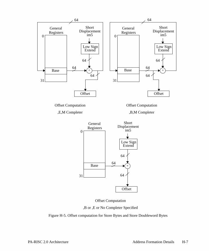
Figure H-5. Offset computation for Store Bytes and Store Doubleword Bytes
0
31
Base
GeneralRegisters
64+
64
64
64
ShortDisplacement
im5
Offset
Low SignExtend
Offset Computation
,E,M Completer
0
31
Base
GeneralRegisters
64+
64
64
64
ShortDisplacement
im5
Offset
Low SignExtend
0
31
Base
GeneralRegisters
64+
64
64
ShortDisplacement
im5
Offset
Low SignExtend
Offset Computation
,B,M Completer
Offset Computation
,B or ,E or No Completer Specified
H-7PA-RISC 2.0 Architecture Address Formation Details

erencen. The
wordsults in
-11).
ear in
e H-2).n in
H-3 on
Indexed Addressing
This section describes memory reference instruction formats, where the effective memory refaddress is formed by the addition of an index value to a base value specified in the instructioentity being transferred can be a doubleword, word, halfword, or a byte.
The format for indexed instructions is:
Theu field specifies is the index register is shifted by the data size specified in theext4 field and themfield specifies if base register modification is performed.
Index shift by data size means that the index value (contents of GRx) is multiplied by the size of thedata item being referenced - 1 if it is a byte, 2 for a halfword, 4 for a word, and 8 for a double(these correspond to shifts by 0, 1, 2, and 3 bits, respectively). Base register modification also rethe contents of GRb being replaced by the sum of the index value and the previous contents of GRb.
Thecc field specifies the cache control hint (see Table 6-7 on page 6-10 and Table 6-9 on page 6
In the instruction descriptions, the termcmplt is used to denote the completer which is encoded in thuand m fields. The list of completers and the address formation functions they specify appeTable H-3.
In the above table,cmplt is in assembly language format andu andm are in machine language format.
The space identifier is computed like any other data memory reference (see Figure H-1 on pagThe calculation of the offset portion of the effective address for different completers is showFigure H-6. Space and offset are combined like any other data memory reference (see Figurepage H-3).
03 b x s u 0 cc ext4 m t
6 5 5 2 1 1 2 4 1 5
Table H-3. Indexed Instruction Completers
cmplt Description u m
<none> no index shift, don’t modify base register 0 0
M no index shift, Modify base register 0 1
S Shift index by data size, don’t modify base register 1 0
SM or S,M Shift index by data size, Modify base register 1 1
H-8 Address Formation Details PA-RISC 2.0 Architecture

pecifiesC 1.0
Absolute Address Formation
The formation of absolute addresses varies depending on the setting of the PSW W-bit which swhether the system is to support full 64-bit offsets or the 32-bit offsets compatible with PA-RISand 1.1 systems.
Figure H-6. Offset computation with indexed addressing
Offset ComputationOffset Computation
,S Completer ,M Completer
Offset Computation
Offset
left
Offset Computation
General Registers0
Base
Shifted
Offset
64
31
Indexshift
64
64
,SM or ,S,M Completer No Completer Specified
Index
General Registers0
Base64
31
64
64
Index
Offset
left
General Registers0
Base
Shifted
64
31
Indexshift
64
64
Index
Offset
General Registers0
Base64
31
64
Index
64
H-9PA-RISC 2.0 Architecture Address Formation Details
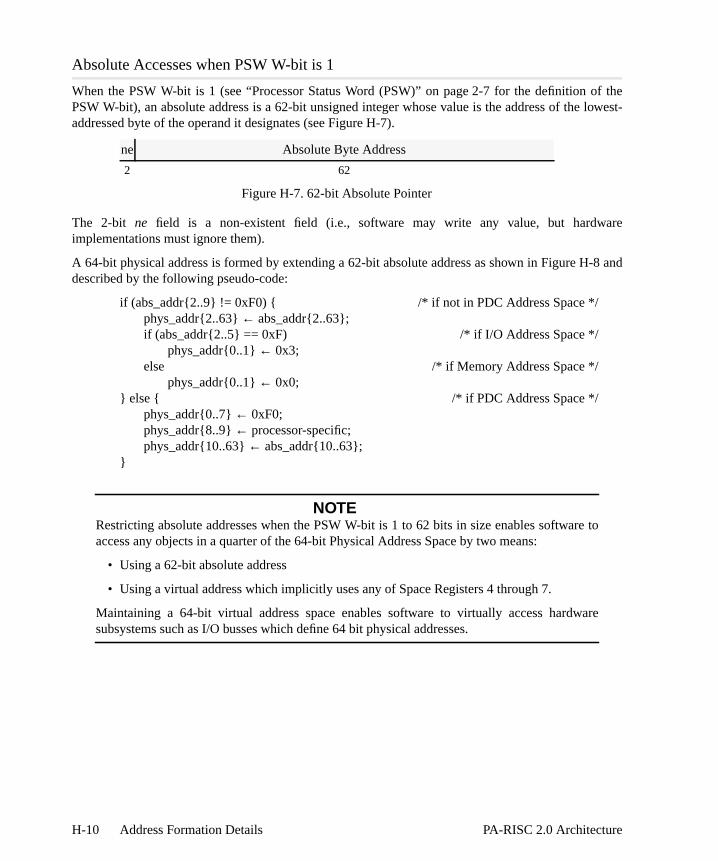
of the lowest-
are
-8 and
to
re
Absolute Accesses when PSW W-bit is 1
When the PSW W-bit is 1 (see “Processor Status Word (PSW)” on page 2-7 for the definition PSW W-bit), an absolute address is a 62-bit unsigned integer whose value is the address of theaddressed byte of the operand it designates (see Figure H-7).
The 2-bit ne field is a non-existent field (i.e., software may write any value, but hardwimplementations must ignore them).
A 64-bit physical address is formed by extending a 62-bit absolute address as shown in Figure Hdescribed by the following pseudo-code:
if (abs_addr{2..9} != 0xF0) { /* if not in PDC Address Space */phys_addr{2..63}← abs_addr{2..63};if (abs_addr{2..5} == 0xF) /* if I/O Address Space */
phys_addr{0..1}← 0x3;else /* if Memory Address Space */
phys_addr{0..1}← 0x0;} else { /* if PDC Address Space */
phys_addr{0..7}← 0xF0;phys_addr{8..9}← processor-specific;phys_addr{10..63}← abs_addr{10..63};
}
NOTERestricting absolute addresses when the PSW W-bit is 1 to 62 bits in size enables softwareaccess any objects in a quarter of the 64-bit Physical Address Space by two means:
• Using a 62-bit absolute address
• Using a virtual address which implicitly uses any of Space Registers 4 through 7.
Maintaining a 64-bit virtual address space enables software to virtually access hardwasubsystems such as I/O busses which define 64 bit physical addresses.
ne Absolute Byte Address
2 62
Figure H-7. 62-bit Absolute Pointer
H-10 Address Formation Details PA-RISC 2.0 Architecture

dress of
H-10
Absolute Accesses when PSW W-bit is 0
When the PSW W-bit is 0, an absolute address is a 32-bit unsigned integer whose value is the adthe lowest-addressed byte of the operand it designates (see Figure H-9)
A 64-bit physical address is formed by extending the 32-bit Absolute Address as shown in Figureand described by the following pseudo-code:
Figure H-8. 62-bit Absolute Accesses when PSW W-bit is 1
non-existent Absolute Byte Address
32 32
Figure H-9. 32-bit Absolute Pointer
PDC AddressSpace
0xF0000000 00000000
0xF1000000 00000000
0xFFFFFFFF FFFFFFFF
0x00000000 00000000
MemoryAddress Space
0x3C000000 00000000
0xFC400000 00000000
MemoryAddress Space
PDC Add. Sp.
I/O AddressSpace
0x00000000 00000000
0x3C000000 00000000
0x3C400000 00000000
0x3FFFFFFF FFFFFFFF
62-bit AbsoluteAccesses withPSW W-bit = 1
64 bit PhysicalAddress Space
I/O AddressSpace
Bits 0 and 1 ofabsolute address are
non-existent andmust be ignored by
hardwareimplementations
H-11PA-RISC 2.0 Architecture Address Formation Details

if (abs_addr{32..39} != 0xF0) { /* if not in PDC Address Space */phys_addr{32..63}← abs_addr{32..63};if (abs_addr{32..35} == 0xF) /* if I/O Address Space */
phys_addr{0..31}← 0xFFFFFFFF;else /* if Memory Address Space */
phys_addr{0..31}← 0x00000000;} else { /* if PDC Address Space */
phys_addr{0..7}← 0xF0;phys_addr{8..39}← processor-specific;phys_addr{40..63}← abs_addr{40..63};
}
Figure H-10. 32-bit Absolute Accesses when PSW W-bit is 0
PDC AddressSpace
0xF0000000 00000000
0xF1000000 00000000
0xFFFFFFFF FFFFFFFF
0x00000000 00000000
I/O AddressSpace
MemoryAddress Space
0x00000000 F0000000
0xFFFFFFFF F1000000
MemoryAddress Space
PDC Add. Sp.
I/O Add. Sp.
0x00000000
0xF0000000
0xF1000000
0xFFFFFFFF
32-bit AbsoluteAccesses withPSW W-bit = 0
64 bit PhysicalAddress Space
H-12 Address Formation Details PA-RISC 2.0 Architecture

ccesses
Figure H-11 illustrates the relationship between the 64-bit Physical Address Space, absolute awhen the PSW W-bit is 0, and an example, 40-bit, implemented physical address space..
Figure H-11. Physical Address Space Mapping - An Example
PDC Add. Sp.
I/O Add. Sp.
MemoryAddress Space
PDC AddressSpace
PDC AddressSpace
0xF0000000 00000000
0xF1000000 00000000
0xFFFFFFFF FFFFFFFF
0x00000000 00000000
MemoryAddress Space
0x00 00000000
0x00 EFFFFFFF
0xF0 00000000
0xFF FFFFFFFF
0x000000EF FFFFFFFF
0xFFFFFFF1 00000000
0x00000000
0xF0000000
0xF1000000
0xFFFFFFFFI/O AddressSpace
I/O AddressSpace
AbsoluteAccesses withPSW W-bit = 0
40-bit PhysicalAddress SpaceImplementation
64-bit PhysicalAddress Space
MemoryAddress Space
H-13PA-RISC 2.0 Architecture Address Formation Details

H-14 Address Formation Details PA-RISC 2.0 Architecture

ow to
. Sincedress,
resting
branche andh willarget ofction,
the IAlue as
I Programming Notes
This appendix is a collection of programming tips and notes that provide brief examples of heffectively use the PA-RISC instruction set to accomplish commonly needed operations.
The following topics are covered:
• privilege level changes
• testing the current state of the PSW[W] bit
• branching
• static branch prediction
• returning from interruption
• trap handlers
• reserved op exception
• endian byte swapping
• halfword byte swap
• word byte swap
• doubleword byte swap
Privilege Level Changes
Branch instructions may change the privilege level depending on the type of branch performedprivilege levels are determined by the two rightmost bits in the offset part of the instruction adprivilege level changes are a function of the offset computation.
Since a branch instruction may be executed in the delay slot of another branch instruction, an intecase arises because of the way the privilege level changes are defined to take effect.
Consider the case where a taken IA relative branch is placed in the delay slot of a base relativethat lowers the privilege level of its target instruction. First, the base relative branch will executschedule change of privilege level for its target. Then, in the delay slot, the IA relative brancexecute and it will schedule its target to execute at the same privilege level as its own. Then, the tthe base relative branch will execute at the new (demoted) privileged level. The next instruhowever, which is the target of the IA relative branch, will have the same privilege level as that of relative branch, and thus will cause the privilege level to be restored to the original (higher) va
I-1PA-RISC 2.0 Architecture Programming Notes

ation is
shown in the following:
Testing the Current State of the PSW W-Bit
Some code may wish to be callable from code which may be running with either narrow or wideaddressing.
The following instruction sequence can be used to determine whether wide 64-bit address generenabled. The value of PSW[W] is returned in register r28 (0=narrow, 1=wide).
PROGRAM SEGMENT
Location Instruction Comment
100 STW r7, 0(r8) ; non-branch instruction
104 BV r0(r7) ; branch vectored to 200 and change priv -> 2
108 BLR r4, r0 ; IA relative branch to location 400
10C ADD r2,r6, r9 ; next instruction in linear code sequence
. .
. .
. .
200 LDW 0(r3), r11 ; target of branch vectored instruction
. .
. .
. .
400 LDW 0(r15), r4 ; target of IA relative branch instruction
404 STW r4, 0(r18)
EXECUTION SEQUENCE
Location Instruction Comment
100 STW r7, 0(r8) ; priv = 0
104 BV r0(r7) ; priv = 0
108 BLR r4, r0 ; priv = 0
200 LDW 0(r3), r11 ; priv = 2 decreased by branch vectored instr
400 LDW 0(r15), r4 ; priv = 0 changed back by IA relative branch
404 STW r4, 0(r18) ; priv = 0
PROGRAM SEGMENT
Location Instruction Comment
100 ADDB,*>,N %r0,%r0,label ; branch if narrow addressing
104 BV 0(2) ; return
I-2 Programming Notes PA-RISC 2.0 Architecture

below.that ofhat the
ntionsor nottion). of the
ortant has beenhese
Procedure Call and Return
Example instruction sequences which perform the different types of procedure calls are shownThe following examples illustrate ways to use offsets of different lengths. The simplest case is intraspace calls which can be done by any of the following code sequences, assuming tconvention that SR 4 tracks IASQ is observed:
Making interspace calls which might decrease privilege level is shown below:
Static Branch Prediction
Branch prediction is quite important to overall performance. PA-RISC includes a set of convewhich allow the programmer to indicate whether a particular branch is more likely to be taken taken (based on static information, or on information obtained from feedback-directed compilaThe way this information is encoded in the branch instructions does not change the semanticsinstructions, but only provides hints to improve the success in predicting branch outcomes.
The static prediction hints are encoded by utilizing the fact that there are, in many of the impcases, two ways of specifying the same branching operation. For such cases, one of these waysdefined to carry the static hint of ‘likely taken’, and the other, the static hint of ‘likely not taken’. T
108 LDI 1,%r28 ; return a 1
label:
10C BV 0(2) ; return
110 LDI 0,%r28 ; return a 0
call: B,L target,rp or LDIL l%target,rp
<delay slot> BE,L r%target(SR4,rp),SR0,GR31
COPY GR31,rp ;delay slot
return: BV 0(rp) or BE 0(SR0,rp)
<delay slot> <delay slot>
call: LDW space_id,GR1 or LDIL l%target, rp
MTSP GR1,SR4 LDO r%target, rp, rp
LDIL l%target,rp BVE,L (rp),rp
BE,L r%target(SR4,rp),SR0,GR31 <delay slot>
COPY GR31,rp ;delay slot
return: BE 0(SR0,rp) or BVE (rp)
<delay slot> <delay slot>
PROGRAM SEGMENT
I-3PA-RISC 2.0 Architecture Programming Notes

en’.
lwaysds onost of
the
he twof the r1ranchesint is
r the
ructionon anitional
ys berward or
hints also take into account whether the branch is backward or forward.
All of the unconditional branches (B, BLR, BV, BE, BVE) are defined to carry the hint of ‘likely tak
For the conditional branches, the hint is defined as follows. If the ,TR completer is specified (ataken), then the hint is defined to be ‘likely taken’. For other branch conditions, the hint depenwhether the branch is forward (positive displacement) or backward (negative displacement). For mthe conditional branches (ADDB, ADDIB, BB, CMPIB, MOVB, MOVIB), backward branches havehint ‘likely taken’ and forward branches have the hint ‘likely not taken’.
For CMPB, there is additional flexibility. Since the same comparison can be made by swapping toperands and choosing the opposite condition, this can be used to encode the branch hint. Iregister specifier is a lower-numbered register than the r2 register specifier, then backward bhave the hint ‘likely taken’ and forward branches have the hint ‘likely not taken’, otherwise the hthe opposite.
These branch hints are summarized in the following table.
Additionally, if a branch is executed in the shadow of a ‘likely taken’ branch, then the prediction fosecond branch is ‘likely not taken’, regardless of the above table.
There are situations where it is desirable to code a branching sequence as a nullifying instfollowed by an unconditional branch. An example would be if one wanted to branch based extract/deposit condition. In such cases, if the branch is likely taken, then a normal uncondbranch can be used.
If the branch is likely not taken, this can be achieved by using a conditional branch which will alwataken, and which has the desired hint. The branch to use depends on whether the target is foback. The two cases are shown below.
STATIC BRANCH PREDICTION HINTS
Unconditional Conditional
B, BLR, BV,BE, BVE
,TR condition other conditions
ADDB, ADDIB,BB, CMPIB,
MOVB, MOVIB,CMPB
ADDB, ADDIB,BB, CMPIB,
MOVB, MOVIB,CMPB with r1<r2 CMPB with r1>=r2
taken taken backward: takenforward: not taken
backward: not takenforward: taken
EXECUTION SEQUENCE
Location Instruction Comment
100 EXTR,= r4,15,16,r0 ; if bit field is not zero
104 B target ; then branch (predicted taken)
I-4 Programming Notes PA-RISC 2.0 Architecture

ctivelyely not
MB ise table
returney
d 25 are general
y of theperating
t set the
If the target of the branch is forward, then we can use the following sequence. The COMIB is effean unconditional branch. Since the branch is forward, the above table shows the COMIB to be liktaken.
If the target of the branch is backward, then we can use this sequence. Here again, the COeffectively an unconditional branch. Since the branch is backward, and since r1 = r2, the abovshows the COMB to be likely not taken.
Return from Interruption
Only those interruptions which are themselves uninterruptible (they leave the PSW Q-bit 0) mayfrom the interruption using theRFI,R instruction. Interruption handling code which is interruptible (thset the PSW Q-bit to 1) must return from the interruption using theRFI instruction.
Fast interruption handling is achieved using shadow registers, since GRs 1, 8, 9, 16, 17, 24, ancopied to the shadow registers on interruptions. In this example, it is assumed that at most sevenregisters need to be used in the interruption handling routine.
Trap Handlers
The IEEE standard strongly recommends that users be allowed to specify a trap handler for anfive standard exceptions. The mechanisms to accomplish this are programming language and osystem dependent.
Since the coprocessor continues to trap if the Status Register T-bit is 1, the trap handler must firs
EXECUTION SEQUENCE
Location Instruction Comment
100 EXTR,= r4,15,16,r0 ; if bit field is not zero
104 COMIB,<> 1,r0,forward_target ; then branch (predicted not taken)
EXECUTION SEQUENCE
Location Instruction Comment
100 EXTR,= r4,15,16,r0 ; if bit field is not zero
104 COMB,= r0,r0,backward_target ; then branch (predicted not taken)
using RFI using RFI,R
interrupt interrupt
save GRs <no save>
[process interrupt] [process interrupt]
restore GRs <no restore>
RFI RFI,R
I-5PA-RISC 2.0 Architecture Programming Notes

te the and
. If the to the
d in the beingnding
s to theented,lues by
ither a
. It doesegister.
ister T-rved-op
by the
versa byte
n r26.
bit to 0 by executing a double-word store of register 0. The trap handler may then emulainstructions in the exception queue beginning with the instruction in Exception Register 1proceeding sequentially to the end.
The trap handler must clear all the exception registers before returning with the T-bit cleared to 0trap handler chooses not to emulate all the instructions, it must set the T-bit to 1 before returningtrapped process to trap immediately again.
To emulate an instruction, the trap handler computes or specifies a substitute result to be placedestination register of the operation. The trap handler may determine what operation wasperformed and what exceptions occurred during the operation by examining the correspoexception register. On overflow, underflow, and inexact exceptions, the trap handler has accescorrectly rounded result by examining the destination register of the operation. On unimpleminvalid operation, and divide-by-zero exceptions, the trap handler has access to the operand vaexamining the source registers of the instruction.
Reserved-op Exception
When a non-load/store instruction has a reserved sub-opcode, an implementation signals ereserved-op exception or an unimplemented exception.
A reserved-op exception always forces the processor to take an immediate assist exception trapnot set the exception registers or the T-bit, and does not change any of the flag bits in the Status RThe reserved-op exception cannot be disabled.
Trapping is immediate for reserved-op exceptions. The trap handler must check for a Status Regbit equal to 0 to determine that the trap was caused by a reserved-op exception. When a reseexception occurs, software interprets the contents of the IIR, nullifies the instruction pointed to front of the IIA queues, and returns control to the trapping process.
Endian Byte Swapping
Rearranging bytes within halfwords, words or doublewords from little endian to big endian or vicecan be accomplished with just a few instructions. The three examples that follow illustrateswapping for the common cases.
Halfword Byte Swap
The following instruction sequence returns in register r28 the byte-reversed halfword value held i
PROGRAM SEGMENT
Location Instruction Comment
100 EXTRW,U %r26,23,8,%r28 ; extract instruction
104 BV 0(2) ; return
108 DEPW %r26,23,8,%r28 ; deposit instruction
I-6 Programming Notes PA-RISC 2.0 Architecture

6.
eld in
The following figure illustrates how the bytes are manipulated during this instruction sequence
Word Byte Swap
The following instruction sequence returns in register r28 the byte-reversed word value held in r2
The following figure illustrates how the bytes are manipulated during this instruction sequence
Doubleword Byte Swap
The following instruction sequence returns in register r28 the byte-reversed doubleword value h
PROGRAM SEGMENT
Location Instruction Comment
100 SHRPW %r26,%r26,16,%r28 ; shift right instruction
104 DEPW %r28,15,8,%r28 ; deposit instruction
108 BV 0(2) ; return
10C SHRPW %r26,%r28,8,%r28 ;shift right
r26 r28
b0 0 a EXTRW,U r26, 23, 8, r28 a0 0 0
Inputs OutputInstruction
r26
b0 0 a
r28
a0 0 bDEPW r26, 23, 8, r28
r28
a0 0 0
r26 r28
da b c SHRPW r26, r26, 16, r28
r26
da b c bc d a
Inputs OutputInstruction
r28
bc d a
r26
da b c
r28
bc b a
r28
bc b aDEPW r28, 15, 8, r28
SHRPW r26, r28, 8, r28
r28
ad c b
I-7PA-RISC 2.0 Architecture Programming Notes

r26. The original value in r26 is destroyed.
The following figure illustrates how the bytes are manipulated during this instruction sequence:
PROGRAM SEGMENT
Location Instruction Comment
100 PERMH,3210
%r26,%r26 ;permute instruction
104 HSHL %r26,8,%r28 ; shift
108 HSHR,U %r26,8,%r26 ; shift
10C BV 0(%r2) ;return
202 OR %r28,%r26,%r28 ;OR the shifted registers
PERMH,3210 r26, r26
Inputs OutputInstruction
r26
da b c
HSHL r26, 8, r28
he f g
r26
fg h e bc d a
r26
0h 0 f 0d 0 b
r26
e0 g 0 a0 c 0
r28
eh g f ad c b
r28
0h 0 f 0d 0 b
r26
e0 g 0 a0 c 0
r26
fg h e bc d a
r26
fg h e bc d a HSHR,U r26, 8, r26
OR r28, r26, r28
I-8 Programming Notes PA-RISC 2.0 Architecture

rs
somendix isd maylly, the
easilypleters
related
a “*”
how toleterss all of
J PA-RISC 2 Instruction Complete & Pseudo-Ops
The instruction set descriptions provided in this book use instruction mnemonics that differ in subtle (and not so subtle) ways from the earlier PA-RISC instruction set descriptions. This appeintended as an aid to those who were familiar with the 1.0 and 1.1 instruction mnemonics anwonder where their favorite instructions that they remember from the old days have gone. Generaanswer is that those instructions have simply been given a new, sleeker identity.
The motivation behind this renaming/reorganizing effort was to present a simpler, more understood view of the PA-RISC instruction set. The major changes involve the use of more comand the introduction of a number of new pseudo-op mnemonics .
PA-RISC 2 Instruction Completers
The 2.0 instruction mnemonics use more completers instead of separate instructions for closelyfunctions. For example, the 1.x read and write versions of thePROBE instruction were replaced in 2.0 bya singlePROBE instruction with two completers,R andW. All 64-bit conditions on the arithmetic andlogical instructions provide new condition completers using the existing 32-bit symbols but with prepended.
One problem which occurs when multiple encodings are compressed into a single mnemonic isforce a particular encoding if you really care (for example, when writing test code). New comphave been added in 2.0 to allow the programmer to force the desired encoding. Table J-1 showthe completers that can be used with PA-RISC 2.0.
Table J-1. Summary of PA 2.0 Instruction Completers
Completer Meaning
B borrowC carryCA0 – CA6 floating-point condition array bits 0 – 6DB doubleword borrowDC doubleword carryDW doublewordGATE gatewayI intermediateL logical
locallinkleft
NWC no word carriesNWZ no words zeroPOP pop branch target stack
J-1PA-RISC 2.0 Architecture PA-RISC 2 Instruction Completers & Pseudo-Ops

PUSH push branch target stackQW quadwordR read
restoreright
S signedSWC some word carrySWZ some word zeroT truncateTC trap on conditionTSV trap on signed overflowU unsignedUDW unsigned doublewordUQW unsigned quadwordUW unsigned wordW wide
wordwrite
Z zero* 64-bit never condition*= 64-bit equal condition*< 64-bit less than condition*<= 64-bit less than or equal to condition*<< 64-bit unsigned less than condition*<<= 64-bit unsigned less than or equal-to condition*SV 64-bit signed overflow condition*OD 64-bit odd condition*TR 64-bit always condition*<> 64-bit not equal condition*>= 64-bit greater than or equal to condition*> 64-bit greater than condition*>>= 64-bit unsigned greater than or equal to condition*>> 64-bit unsigned greater than condition*NSV 64-bit no signed overflow condition*EV 64-bit even condition*NUV 64-bit no unsigned overflow condition*ZNV 64-bit zero or no unsigned overflow condition*UV 64-bit unsigned overflow condition*VNZ 64-bit nonzero and unsigned overflow condition*NBC 64-bit no byte carries condition*NBZ 64-bit no bytes zero condition*NDC 64-bit no digit carries condition*NHC 64-bit no halfword carries condition
Table J-1. Summary of PA 2.0 Instruction Completers (Continued)
Completer Meaning
J-2 PA-RISC 2 Instruction Completers & Pseudo-Ops PA-RISC 2.0 Architecture

le J-2.
Pseudo-Op Mnemonics
All 1.x instruction mnemonics are supported either directly or via 2.0 pseudo-ops as listed in TabNote that only 1.x instructions whose mnemonics changed are listed in Table J-2.
*NHZ 64-bit no halfwords zero condition*NWC 64-bit no word carries condition*NWZ 64-bit no words zero condition*SBC 64-bit some byte carry condition*SBZ 64-bit some byte zero condition*SDC 64-bit some digit carry condition*SHC 64-bit some halfword carry condition*SHZ 64-bit some halfword zero condition*SWC 64-bit some word carry condition*SWZ 64-bit some word zero conditionLDISP force long-displacement encoding for loads, stores, branchesSDISP force short-displacement encoding for loads, stores, branches0C force 0C encoding for floating-point0E force 0E encoding for floating-point0A force 0A encoding forFIC4F force 4F encoding forFIC
Table J-2. 1.x versus 2.0 Mnemonics
1.x Instruction 2.0 Instruction
ADDBF,cond,n r1,r2,target ADDB,cond,n r1,r2,target
ADDBT,cond,n r1,r2,target ADDB,cond,n r1,r2,target
ADDC,cond r1,r2,t ADD,C,cond r1,r2,t
ADDCO,cond r1,r2,t ADD,C,TSV,cond r1,r2,t
ADDIBF,cond,n i,r,target ADDIB,cond,n i,r,target
ADDIBT,cond,n i,r,target ADDIB,cond,n i,r,target
ADDIL i,r ADDIL i,r,%R1
ADDIO,cond i,r,t ADDI,TSV,cond i,r,t
ADDIT,cond i,r,t ADDI,TC,cond i,r,t
ADDITO,cond i,r,t ADDI,TSV,TC,cond i,r,t
ADDL,cond r1,r2,t ADD,L,cond r1,r2,t
ADDO,cond r1,r2,t ADD,TSV,cond r1,r2,t
BL,n target,t B,L,n target,t
BLE,n wd(sr,b) BE,L,n wd(sr,b),%SR0,%R31
BVB,cond,n r,target BB,cond,n r,%SAR,target
CLDDS,uid,cmplt,cc d(s,b),t CLDD,uid,cmplt,cc d(s,b),t
Table J-1. Summary of PA 2.0 Instruction Completers (Continued)
Completer Meaning
J-3PA-RISC 2.0 Architecture PA-RISC 2 Instruction Completers & Pseudo-Ops

CLDDX,uid,cmplt,cc x(s,b),t CLDD,uid,cmplt,cc x(s,b),t
CLDWS,uid,cmplt,cc d(s,b),t CLDW,uid,cmplt,cc d(s,b),t
CLDWX,uid,cmplt,cc x(s,b),t CLDW,uid,cmplt,cc x(s,b),t
COMBF,cond,n r1,r2,target CMPB,cond,n r1,r2,target
COMBT,cond,n r1,r2,target CMPB,cond,n r1,r2,target
COMIBF,cond,n i,r,target CMPIB,cond,n i,r,target
COMIBT,cond,n i,r,target CMPIB,cond,n i,r,target
COMICLR,cond i,r,t CMPICLR,cond i,r,t
CSTDS,uid,cmplt,cc r,d(s,b) CSTD,uid,cmplt,cc r,d(s,b)
CSTDX,uid,cmplt,cc r,x(s,b) CSTD,uid,cmplt,cc r,x(s,b)
CSTWS,uid,cmplt,cc r,d(s,b) CSTW,uid,cmplt,cc r,d(s,b)
CSTWX,uid,cmplt,cc r,x(s,b) CSTW,uid,cmplt,cc r,x(s,b)
DEP,cond r,p,len,t DEPW,cond r,p,len,t
DEPI,cond i,p,len,t DEPWI,cond i,p,len,t
EXTRS,cond r,p,len,t EXTRW,S,cond r,p,len,t
EXTRU,cond r,p,len,t EXTRW,U,cond r,p,len,t
FCNVFF,sf,df r,t FCNV,sf,df r,t
FCNVFX,sf,df r,t FCNV,sf,df r,t
FCNVFXT,sf,df r,t FCNV,T,sf,df r,t
FCNVXF,sf,df r,t FCNV,sf,df r,t
FLDDS,cmplt,cc d(s,b),t FLDD,cmplt,cc d(s,b),t
FLDDX,cmplt,cc x(s,b),t FLDD,cmplt,cc x(s,b),t
FLDWS,cmplt,cc d(s,b),t FLDW,cmplt,cc d(s,b),t
FLDWX,cmplt,cc x(s,b),t FLDW,cmplt,cc x(s,b),t
FSTDS,cmplt,cc r,d(s,b) FSTD,cmplt,cc r,d(s,b)
FSTDX,cmplt,cc r,x(s,b) FSTD,cmplt,cc r,x(s,b)
FSTWS,cmplt,cc r,d(s,b) FSTW,cmplt,cc r,d(s,b)
FSTWX,cmplt,cc r,x(s,b) FSTW,cmplt,cc r,x(s,b)
GATE,n target,t B,GATE,n target,t
IDCOR,cond r,t DCOR,I,cond r,t
LDBS,cmplt,cc d(s,b),t LDB,cmplt,cc d(s,b),t
LDBX,cmplt,cc x(s,b),t LDB,cmplt,cc x(s,b),t
LDCWS,cmplt,cc d(s,b),t LDCW,cmplt,cc d(s,b),t
LDCWX,cmplt,cc x(s,b),t LDCW,cmplt,cc x(s,b),t
LDHS,cmplt,cc d(s,b),t LDH,cmplt,cc d(s,b),t
LDHX,cmplt,cc x(s,b),t LDH,cmplt,cc x(s,b),t
LDWAS,cmplt,cc d(b),t LDWA,cmplt,cc d(b),t
Table J-2. 1.x versus 2.0 Mnemonics (Continued)
1.x Instruction 2.0 Instruction
J-4 PA-RISC 2 Instruction Completers & Pseudo-Ops PA-RISC 2.0 Architecture

LDWAX,cmplt,cc x(b),t LDWA,cmplt,cc x(b),t
LDWM d(s,b),t LDW,cmplt ld(s,b),t
LDWS,cmplt,cc d(s,b),t LDW,cmplt,cc d(s,b),t
LDWX,cmplt,cc x(s,b),t LDW,cmplt,cc x(s,b),t
PROBER (s,b),r,t PROBE,R (s,b),r,t
PROBERI (s,b),i,t PROBEI,R (s,b),i,t
PROBEW (s,b),r,t PROBE,W (s,b),r,t
PROBEWI (s,b),i,t PROBEI,W (s,b),i,t
RFIR RFI,R
SH1ADD,cond r1,r2,t SHLADD,cond r1,1,r2,t
SH1ADDL,cond r1,r2,t SHLADD,L,cond r1,1,r2,t
SH1ADDO,cond r1,r2,t SHLADD,TSV,cond r1,1,r2,t
SH2ADD,cond r1,r2,t SHLADD,cond r1,2,r2,t
SH2ADDL,cond r1,r2,t SHLADD,L,cond r1,2,r2,t
SH2ADDO,cond r1,r2,t SHLADD,TSV,cond r1,2,r2,t
SH3ADD,cond r1,r2,t SHLADD,cond r1,3,r2,t
SH3ADDL,cond r1,r2,t SHLADD,L,cond r1,3,r2,t
SH3ADDO,cond r1,r2,t SHLADD,TSV,cond r1,3,r2,t
SHD,cond r1,r2,p,t SHRPW,cond r1,r2,p,t
STBS,cmplt,cc r,d(s,b) STB,cmplt,cc r,d(s,b)
STBYS,cmplt,cc r,d(s,b) STBY,cmplt,cc r,d(s,b)
STHS,cmplt,cc r,d(s,b) STH,cmplt,cc r,d(s,b)
STWAS,cmplt,cc r,d(b) STWA,cmplt,cc r,d(b)
STWM r,d(s,b) STW,cmplt r,ld(s,b)
STWS,cmplt,cc r,d(s,b) STW,cmplt,cc r,d(s,b)
SUBB,cond r1,r2,t SUB,B,cond r1,r2,t
SUBBO,cond r1,r2,t SUB,B,TSV,cond r1,r2,t
SUBIO,cond i,r,t SUBI,TSV,cond i,r,t
SUBO,cond r1,r2,t SUB,TSV,cond r1,r2,t
SUBT,cond r1,r2,t SUB,TC,cond r1,r2,t
SUBTO,cond r1,r2,t SUB,TSV,TC,cond r1,r2,t
UADDCMT,cond r1,r2,t UADDCM,TC,cond r1,r2,t
VDEP,cond r,len,t DEPW,cond r,%SAR,len,t
VDEPI,cond i,len,t DEPWI,cond i,%SAR,len,t
VEXTRS,cond r,len,t EXTRW,S,cond r,%SAR,len,t
VEXTRU,cond r,len,t EXTRW,U,cond r,%SAR,len,t
Table J-2. 1.x versus 2.0 Mnemonics (Continued)
1.x Instruction 2.0 Instruction
J-5PA-RISC 2.0 Architecture PA-RISC 2 Instruction Completers & Pseudo-Ops

VSHD,cond r1,r2,t SHRPW,cond r1,r2,%SAR,t
ZDEP,cond r,p,len,t DEPW,Z,cond r,p,len,t
ZDEPI,cond i,p,len,t DEPWI,Z,cond i,p,len,t
ZVDEP,cond r,len,t DEPW,Z,cond r,%SAR,len,t
ZVDEPI,cond i,len,t DEPWI,Z,cond i,%SAR,len,t
Table J-2. 1.x versus 2.0 Mnemonics (Continued)
1.x Instruction 2.0 Instruction
J-6 PA-RISC 2 Instruction Completers & Pseudo-Ops PA-RISC 2.0 Architecture
Index
Aabsolute accesses3-1, G-2absolute_address()E-2access ID 3-13access rights 3-13access type
execute 3-12read 3-12write 3-12
ADD 7-2ADD (seeADD)ADD AND BRANCH 7-4ADD IMMEDIATE AND BRANCH 7-6ADD IMMEDIATE LEFT 7-7ADD TO IMMEDIATE 7-5ADDB (seeADD AND BRANCH)ADDI (seeADD TO IMMEDIATE)ADDIB (seeADD IMMEDIATE AND BRANCH)ADDIL (seeADD IMMEDIATE LEFT)address aliasingF-5
equivalent aliasesF-6many-reader/one-writerF-6non-equivalent aliasesF-6read-only F-6
AND 7-8AND (seeAND)AND COMPLEMENT 7-9ANDCM (seeAND COMPLEMENT)assemble_12()E-1assemble_16()E-1assemble_16a()E-1assemble_17()E-1assemble_21()E-1assemble_22()E-1assemble_3() E-1assemble_6() E-1assist emulation trap5-12assist exception trap5-9assist processor1-13
atomicity G-1
BB (seeBRANCH)BB (seeBRANCH ON BIT)BCD, (seebinary coded decimal)BE (seeBRANCH EXTERNAL)binary coded decimal7-35binary coded decimal data type2-19bit data type 2-18bits
ignored 2-17nonexistent 2-17reserved 2-17undefined 2-17
Block Copy cache control hint6-10BLR (seeBRANCH AND LINK REGISTER)BRANCH 2-8, 6-14, 7-10BRANCH AND LINK REGISTER 6-14, 7-16BRANCH EXTERNAL 6-15, 7-15BRANCH ON BIT 7-13BRANCH VECTORED 6-14, 7-18BRANCH VECTORED EXTERNAL 6-15, 7-19branches 4-1
base relative 4-2conditional 4-2, 6-15delay slot 4-1delayed 4-1dynamic displacement4-2external 6-15IA relative 4-2interspace 6-15intraspace 6-14local 6-14not-taken 4-2static displacment 4-2taken 4-2unconditional 4-2, 6-14
BREAK 7-17
IN-1PA-RISC 2.0 Architecture Index

r-
BREAK instruction trap 5-8BV (seeBRANCH VECTORED)BVE (seeBRANCH VECTORED EXTERNAL)byte data type 2-18
Ccache
clean 3-17dirty 3-17move-in F-8
cache control hints6-9Block Copy 6-10Coherent Operation6-11load 6-10semaphore 6-10Spacial Locality 6-10store 6-10
CALL 7-11cat() E-1CCR (see Coprocessor Configuration Register)check 5-1CLDD (see COPROCESSOR LOAD DOUBLE-
WORD)CLDW (seeCOPROCESSOR LOAD WORD)CLEAR BRANCH TARGET STACK 7-25CLRBTS (seeCLEAR BRANCH TARGET STACK)CMPB (seeCOMPARE AND BRANCH)CMPCLR (seeCOMPARE AND CLEAR)CMPIB (see COMPARE IMMEDIATE AND
BRANCH)CMPICLR (see COMPARE IMMEDIATE AND
CLEAR)coherence_index()E-2coherent input/ouputF-11Coherent Operation cache control hint6-11coherent_systemE-2COMPARE AND BRANCH 7-26COMPARE AND CLEAR 7-27COMPARE IMMEDIATE AND BRANCH 7-28COMPARE IMMEDIATE AND CLEAR 7-29conditional trap 5-9conditions
arithmetic/logical D-1floating-point compare 8-16floating-point test 8-17shift/extract/deposit D-8
unit D-7control registers 2-10COPR (seeCOPROCESSOR OPERATION)COPR,0,0 (seeIDENTIFY COPROCESSOR)coprocessor 1-13, 6-22Coprocessor Configuration Register2-12, 6-22COPROCESSOR LOAD DOUBLEWORD 7-21COPROCESSOR LOAD WORD 7-23COPROCESSOR OPERATION 7-30COPROCESSOR STORE DOUBLEWORD 7-31COPROCESSOR STORE WORD 7-33coprocessor_condition()E-2coprocessor_op()E-2COPY 7-82CRs (see control registers)CSTD (see COPROCESSOR STORE DOUBLE-
WORD)CSTW (seeCOPROCESSOR STORE WORD)
Ddata memory access rights trap5-10data memory break trap5-11data memory protection ID trap5-10data memory protection trap/unaligned data refe
ence trap 5-11data TLB miss fault/data page fault5-9data types
binary coded decimal2-19bit 2-18byte 2-18double-precision floating-point2-19, 8-6integer 2-18quad-precision floating-point8-6signed halfword 2-18signed word 2-18single-precision floating-point2-19, 8-6unsigned halfword 2-18unsigned word 2-19
Dcache_flush() E-3Dcache_flush_entries()E-3Dcache_flush_or_purge()E-3DCOR (seeDECIMAL CORRECT)DECIMAL CORRECT 7-35DEPD (seeDEPOSIT DOUBLEWORD)DEPDI (see DEPOSIT DOUBLEWORD IMMEDI-
ATE)
IN-2 Index PA-RISC 2.0 Architecture

DEPOSIT DOUBLEWORD 7-37DEPOSIT DOUBLEWORD IMMEDIATE 7-39DEPOSIT WORD 7-41DEPOSIT WORD IMMEDIATE 7-43DEPW (seeDEPOSIT WORD)DEPWI (seeDEPOSIT WORD IMMEDIATE)DIAG (seeDIAGNOSE)DIAGNOSE 7-45Direct I/O 1-13Direct Memory Access I/O 1-13DIVIDE STEP 2-8, 7-46double-precision floating-point data type 2-19DS (seeDIVIDE STEP)DTLB_alloc() E-3DTLB_purge_broadcast() E-3DTLB_purge_entries() E-3DTLB_purge_local() E-3DTLB_search() E-3
EEIEM (see External Interrupt Enable Mask)EIRR (see External Interrupt Request Register)endian bit 2-19equivalent aliases F-6equivalently-mapped F-5excepting instruction 10-1EXCLUSIVE OR 7-154external interrupt 5-6External Interrupt Enable Mask 2-13External Interrupt Request Register 2-16EXTRACT DOUBLEWORD 7-47EXTRACT WORD 7-49EXTRD (seeEXTRACT DOUBLEWORD)EXTRW (seeEXTRACT WORD)
FFABS (seeFLOATING-POINT ABSOLUTE VALUE)FADD (seeFLOATING-POINT ADD)fault 5-1FCMP (seeFLOATING-POINT COMPARE)FCNV (seeFLOATING-POINT CONVERT)FCPY (seeFLOATING-POINT COPY)FDC (seeFLUSH DATA CACHE)FDCE (seeFLUSH DATA CACHE ENTRY)FDIV (seeFLOATING-POINT DIVIDE)
FIC (seeFLUSH INSTRUCTION CACHE)FICE (seeFLUSH INSTRUCTION CACHE ENTRY)FID (seeFLOATING-POINT IDENTIFY)FIXED-POINT MULTIPLY UNSIGNED 9-30FLDD (see FLOATING-POINT LOAD DOUBLE-
WORD)FLDW (seeFLOATING-POINT LOAD WORD)floating-point
DBL format completer 8-15delayed trapping 10-5exception registers 10-1exceptions 10-4
division by zero 10-10invalid operation 10-9non-trapping 10-6overflow 10-11reserved operation 10-8, I-6unimplemented 10-8
immediate trapping 10-4interruptions 10-4Not a Number 8-7, 8-23QUAD format completer 8-15registers 8-2rounding 8-22SGL format completer 8-15
FLOATING-POINT ABSOLUTE VALUE 9-2FLOATING-POINT ADD 9-3FLOATING-POINT COMPARE 9-4FLOATING-POINT COPY 9-7FLOATING-POINT DIVIDE 9-8FLOATING-POINT IDENTIFY 9-9FLOATING-POINT LOAD DOUBLEWORD 9-10FLOATING-POINT LOAD WORD 9-12FLOATING-POINT MULTIPLY 9-14FLOATING-POINT MULTIPLY FUSED ADD 9-16FLOATING-POINT MULTIPLY NEGATE FUSED
ADD 9-17FLOATING-POINT MULTIPLY/ADD 9-15FLOATING-POINT MULTIPLY/SUBTRACT 9-18
FLOATING-POINT NEGATE ABSOLUTE VALUE9-20
FLOATING-POINT ROUND TO INTEGER 9-21FLOATING-POINT SQUARE ROOT 9-22Floating-Point Status Register 8-8
C-bit 8-10
IN-3PA-RISC 2.0 Architecture Index

CQ field 8-10D-bit 8-10Enables field 8-9Flags field 8-9I bits 8-10model field 8-11O bits 8-10revision field 8-11RM field 8-9T-bit 8-10U bits 8-10V bits 8-10Z bits 8-10
FLOATING-POINT STORE DOUBLEWORD 9-23FLOATING-POINT STORE WORD 9-25FLOATING-POINT SUBTRACT 9-27FLOATING-POINT TEST 9-28FLUSH DATA CACHE 7-51FLUSH DATA CACHE ENTRY 7-53FLUSH INSTRUCTION CACHE 7-54FLUSH INSTRUCTION CACHE ENTRY 7-56FMPY (seeFLOATING-POINT MULTIPLY)FMPYADD (see FLOATING-POINT MULTIPLY/
ADD)FMPYFADD (see FLOATING-POINT MULTIPLY
FUSED ADD)FMPYNFADD (seeFLOATING-POINT MULTIPLY
NEGATE FUSED ADD)FMPYSUB (see FLOATING-POINT MULTIPLY/
SUBTRACT)FNEG (seeFLOATING-POINT NEGATE)FNEGABS (seeFLOATING-POINT NEGATE ABSO-
LUTE VALUE)FPSR (see Floating-Point Status Register)FRND (seeFLOATING-POINT ROUND TO INTE-
GER)FSQRT (seeFLOATING-POINT SQUARE ROOT)FSTD (see FLOATING-POINT STORE DOUBLE-
WORD)FSTW (seeFLOATING-POINT STORE WORD)FSUB (seeFLOATING-POINT SUBTRACT)FTEST (seeFLOATING-POINT TEST)
Ggeneral registers2-2GRs (see general registers)
HHADD (seeHALFWORD PARALLEL ADD)HALFWORD PARALLEL ADD 7-57HALFWORD PARALLEL AVERAGE 7-58HALFWORD PARALLEL SHIFT LEFT 7-59HALFWORD PARALLEL SHIFT LEFT AND ADD
7-60HALFWORD PARALLEL SHIFT RIGHT 7-61HALFWORD PARALLEL SHIFT RIGHT AND ADD
7-59, 7-62HALFWORD PARALLEL SUBTRACT 7-63HAVG (seeHALFWORD PARALLEL AVERAGE)higher-privilege transfer trap5-13high-priority machine check5-5HSHL(seeHALFWORD PARALLEL SHIFT LEFT)HSHLADD (see HALFWORD PARALLEL SHIFT
LEFT AND ADD)HSHR(seeHALFWORD PARALLEL SHIFT RIGHT)HSHRADD (see HALFWORD PARALLEL SHIFT
RIGHT AND ADD)HSUB (seeHALFWORD PARALLEL SUBTRACT)
II/O (see input/output)IAOQ (see Instruction Address Offset Queue)IAQs (see Instruction Address Queues)IASQ (see Instruction Address Space Queue)Icache_flush() E-3Icache_flush_entries()E-4IDENTIFY COPROCESSOR 6-22, 7-30IDENTIFY SFU 6-21, 7-125IDTLBT (seeINSERT DATA TLB TRANSLATION)IEEE 754 8-1ignored
bits 2-17IIAOQ (see Interruption Instruction Address Off-
set Queue)IIAQs (see Interruption Instruction Address
Queues)IIASQ (see Interruption Instruction Address
Space Queue)IIR (see Interruption Instruction Register)IITLBT (seeINSERT INSTRUCTION TLB TRANS-
LATION)illegal instruction 6-24
IN-4 Index PA-RISC 2.0 Architecture

illegal instruction trap 5-8INCLUSIVE OR 7-101INDIRECT CALL 7-20input/output 1-12INSERT DATA TLB TRANSLATION 7-64INSERT INSTRUCTION TLB TRANSLATION 7-66Instruction Address Offset Queue2-4Instruction Address Queues2-4Instruction Address Space Queue2-4instruction memory protection trap5-7instruction TLB miss fault/instruction page fault
5-7instructions
immediate 6-12integer data type2-18interrupt 5-1Interruption Instruction Address Offset Queue2-
13Interruption Instruction Address Queues2-13Interruption Instruction Address Space Queue2-
13Interruption Instruction Register2-15Interruption Offset Register2-15Interruption Parameter Registers2-15Interruption Processor Status Word2-16Interruption Space Register2-15Interruption Vector Address2-13interruptions
disabling 5-4floating-point 10-4group 1 5-5group 2 4-7, 5-6group 3 4-8, 5-7group 4 4-9, 5-13masking 5-4performance monitor 11-1priorities 5-4
Interval Timer 2-5IO_EIR 2-17IOR (see Interruption Offset Register)IPRs (see Interruption Parameter Registers)IPSW (see Interruption Processor Status Word)ISR (see Interruption Space Register)ITLB_alloc() E-4ITLB_purge_broadcast()E-4ITLB_purge_entries() E-4
ITLB_purge_local() E-4ITLB_search() E-4IVA (see Interruption Vector Address)
LLCI (seeLOAD COHERENCE INDEX)LDB (seeLOAD BYTE)LDCD (seeLOAD AND CLEAR DOUBLEWORD)LDCW (seeLOAD AND CLEAR WORD)LDD (seeLOAD DOUBLEWORD)LDDA (seeLOAD DOUBLEWORD ABSOLUTE)LDH (seeLOAD HALFWORD)LDI (seeLOAD IMMEDIATE)LDIL (seeLOAD IMMEDIATE LEFT)LDO (seeLOAD OFFSET)LDSID (seeLOAD SPACE IDENTIFIER)LDW (seeLOAD WORD)LDWA (seeLOAD WORD ABSOLUTE)LOAD AND CLEAR DOUBLEWORD 7-71LOAD AND CLEAR WORD 7-73LOAD BYTE 7-69LOAD COHERENCE INDEX 7-68LOAD DOUBLEWORD 7-75LOAD DOUBLEWORD ABSOLUTE 7-77LOAD HALFWORD 7-79LOAD IMMEDIATE 7-82LOAD IMMEDIATE LEFT 7-81LOAD OFFSET 7-82LOAD PHYSICAL ADDRESS 7-88LOAD SPACE IDENTIFIER 7-83LOAD WORD 7-84LOAD WORD ABSOLUTE 7-86low_sign_ext() E-1lower-privilege transfer trap5-13low-priority machine check 5-7LPA (seeLOAD PHYSICAL ADDRESS)lshift() E-1
Mmany-reader/one-writer aliasingF-6mask
system 2-7measurement_enabledE-4mem_load() 6-7mem_store() 6-7
IN-5PA-RISC 2.0 Architecture Index

memory-mapped input/ouput1-12MFCTL (seeMOVE FROM CONTROL REGISTER)MFIA (see MOVE FROM INSTRUCTION AD-
DRESS)MFSP (seeMOVE FROM SPACE REGISTER)MIX HALFWORDS 7-92MIX WORDS 7-93MIXH( seeMIX HALFWORDS)MIXW( seeMIX WORDS)MOVB (seeMOVE AND BRANCH)MOVE AND BRANCH 7-94MOVE FROM CONTROL REGISTER 7-89MOVE FROM INSTRUCTION ADDRESS 7-90MOVE FROM SPACE REGISTER 7-91MOVE IMMEDIATE AND BRANCH 7-95MOVE TO CONTROL REGISTER 7-96MOVE TO SHIFT AMOUNT REGISTER 7-96MOVE TO SPACE REGISTER 7-100MOVE TO SYSTEM MASK 7-99move-in
data cache F-8instruction cache F-9
MOVIB (seeMOVE IMMEDIATE AND BRANCH)MTCTL (seeMOVE TO CONTROL REGISTER)MTSAR (seeMOVE TO SHIFT AMOUNT REGIS-
TER)MTSARCM (seeMOVE TO SHIFT AMOUNT REG-
ISTER COMPLEMENT)MTSM (seeMOVE TO SYSTEM MASK)MTSP (seeMOVE TO SPACE REGISTER)Multimedia Instructions 6-3multiprocessor systemsF-12
NNaN (see floating-point,Not a Number)NO OPERATION 7-101non-access data TLB miss fault/non-access data
page fault 5-10non-access instruction TLB miss fault5-9non-equivalent aliasesF-6nonexistent
bits 2-17NOP (seeNO OPERATION)null instructions 6-25nullification 4-7
Oobserved G-1operation
undefined 6-24OR (seeINCLUSIVE OR)ordered G-1ordering G-1overflow
signed D-2unsigned D-2
overflow trap 5-9
Ppage
cacheable 3-17uncacheable 3-17
page reference trap5-12page table 3-15PDC (seePURGE DATA CACHE)PDTLB (seePURGE DATA TLB)PDTLBE (seePURGE DATA TLB ENTRY)performance monitor
interruptions 11-1PERFORMANCE MONITOR DISABLE 11-3PERFORMANCE MONITOR ENABLE 11-4performance monitor interrupt5-7performed G-1PERMH(seePERMUTE HALFWORDS)PERMUTE HALFWORDS 7-106phys_mem_load() E-4phys_mem_store()E-5PIDs (see Protection Identifiers)PITLB (seePURGE INSTRUCTION TLB)PITLBE (seePURGE INSTRUCTION TLB ENTRY)PMDIS (see PERFORMANCE MONITOR DIS-
ABLE)PMENB (see PERFORMANCE MONITOR EN-
ABLE)POP BRANCH TARGET STACK 7-110POPBTS (seePOP BRANCH TARGET STACK)power failure interrupt 5-6Priveleged Software-Accessible Registers2-7privilege level 3-12
changing 4-5, I-1privileged operation trap5-8
IN-6 Index PA-RISC 2.0 Architecture

privileged register trap5-8PROBE ACCESS 7-111PROBE ACCESS IMMEDIATE 7-112PROBE(seePROBE ACCESS)PROBEI (seePROBE ACCESS IMMEDIATE)Processor 2-7Processor Status Word2-7
B-bit 2-8, 4-7, 4-9C/B bits 2-9C-bit 2-8D-bit 2-9E-bit 2-8, 2-19, 5-2F-bit 2-9H-bit 2-8, 4-9I-bit 2-9L-bit 2-8, 4-9M-bit 2-8, 4-7, 5-3N-bit 2-8, 4-7, 4-9O-bit 2-9P-bit 2-9Q-bit 2-9R-bit 2-9, 2-11, 4-9S-bit 2-8T-bit 2-8V-bit 2-8W-bit 5-2X-bit 2-8, 4-7, 4-9
Protection Identifiers 2-12, 3-12PSW (see Processor Status Word)PURGE DATA CACHE 7-102PURGE DATA TLB 7-104PURGE DATA TLB ENTRY 7-105PURGE INSTRUCTION TLB ENTRY 7-109PUSH BRANCH TARGET STACK 7-113PUSH NOMINATED 7-114PUSHBTS (seePUSH BRANCH TARGET STACK)PUSHNOM (seePUSH NOMINATED)
Rread_access_allowed()E-5read-only aliasing F-6read-only translation F-6Recovery Counter 2-11, 4-9recovery counter trap5-6registers
control 2-10
floating-point 8-2floating-point exception 10-1general 2-2reserved 2-17shadow 2-9space 2-3
relied-upon translationF-2reserved
bits 2-17instruction field values 6-25instruction fields 6-24registers 2-17
RESET SYSTEM MASK 7-117RET (seeRETURN)RETURN 7-20RETURN FROM INTERRUPTION 5-4, 7-115RFI (seeRETURN FROM INTERRUPTION)rounding,floating-point 8-22rshift() E-2RSM (seeRESET SYSTEM MASK)
SSAR (see Shift Amount Register)SCR (see SFU Configuration Register)send_to_copr() E-2SET SYSTEM MASK 7-128SFU Configuration Register2-12, 6-21SFU Registers 2-6sfu_condition0() E-5sfu_condition1() E-5sfu_condition2() E-5sfu_condition3() E-5sfu_operation0() E-5sfu_operation1() E-5sfu_operation2() E-5sfu_operation3() E-5shadow registers2-9, 7-115Shift Amount Register 2-5SHIFT LEFT AND ADD 7-118SHIFT LEFT DOUBLEWORD 7-38SHIFT LEFT WORD 7-42SHIFT RIGHT DOUBLEWORD 7-48SHIFT RIGHT PAIR DOUBLEWORD 7-120SHIFT RIGHT PAIR WORD 7-122SHIFT RIGHT WORD 7-50SHLADD (seeSHIFT LEFT AND ADD)
IN-7PA-RISC 2.0 Architecture Index
SHLD (seeSHIFT LEFT DOUBLEWORD)SHLW (seeSHIFT LEFT WORD)SHRD (seeSHIFT RIGHT DOUBLEWORD)SHRPD (seeSHIFT RIGHT PAIR DOUBLEWORD)SHRPW (seeSHIFT RIGHT PAIR WORD)SHRs (see shadow registers)SHRW (seeSHIFT RIGHT WORD)sign_ext() E-2sign_ext_16() E-2signed halfword data type2-18signed overflow D-2signed word data type2-18single-precision floating-point data type2-19space registers2-3space_select()E-6Spacial Locality cache control hint6-10special function unit 1-13, 6-20SPECIAL OPERATION ONE 7-125SPECIAL OPERATION THREE 7-127SPECIAL OPERATION TWO 7-126SPECIAL OPERATION ZERO 7-124SPOP0 (seeSPECIAL OPERATION ZERO)SPOP1 (seeSPECIAL OPERATION ONE)SPOP1,sfu,0 (seeIDENTIFY SFU)SPOP2 (seeSPECIAL OPERATION TWO)SPOP3 (seeSPECIAL OPERATION THREE)SRs (see space registers)SSM (seeSET SYSTEM MASK)STB (seeSTORE BYTE)STBY (seeSTORE BYTES)STD (seeSTORE DOUBLEWORD)STDA (seeSTORE DOUBLEWORD ABSOLUTE)STDBY (seeSTORE DOUBLEWORD BYTES)STH (seeSTORE HALFWORD)STORE BYTE 7-129STORE BYTES 7-131STORE BYTES SHORT 6-12, G-1, H-6STORE DOUBLEWORD 7-134STORE DOUBLEWORD ABSOLUTE 7-136STORE DOUBLEWORD BYTES 7-137STORE HALFWORD 7-140STORE WORD 7-142STORE WORD ABSOLUTE 7-144store_in_memory() E-2strongly ordered G-1STW (seeSTORE WORD)
STWA (seeSTORE WORD ABSOLUTE)SUB (seeSUBTRACT)SUBI (seeSUBTRACT FROM IMMEDIATE)SUBTRACT 7-146SUBTRACT FROM IMMEDIATE 7-148SYNC (seeSYNCHRONIZE CACHES)SYNCDMA (seeSYNCHRONIZE DMA)SYNCHRONIZE CACHES 7-149SYNCHRONIZE DMA 7-150system mask 2-7
Ttaken branch trap5-13temporary registers2-17TLB (see Translation Lookaside Buffer)TLB dirty bit trap 5-12translation
read-only F-6write-capable F-6
Translation Lookaside Buffer3-9access identifier (ID) 3-13access rights 3-13B-bit 3-10combined 3-9D-bit 3-10entry F-1hardware miss hndlingF-3O-bit 3-10relied-upon translationF-2slot F-1software miss handlingF-2T-bit 3-10U-bit 3-10
trap 5-1TRs (see temporary registers)
UUADDCM (seeUNIT ADD COMPLEMENT)unaligned data reference trap5-11undefined
bits 2-17instruction 6-24
undefined operation6-24UNIT ADD COMPLEMENT 7-151UNIT XOR 7-153
IN-8 Index PA-RISC 2.0 Architecture

unsigned halfword data type2-18unsigned overflow D-2unsigned word data type2-19UXOR (seeUNIT XOR)
Vvirt_mem_load() E-6virt_mem_store() E-7virtual accesses3-1
WWD bit 2-12weakly ordered G-1write_access_allowed()E-7write-capable translationF-6
XXMPYU (see FIXED-POINT MULTIPLY UN-
SIGNED)XOR (seeEXCLUSIVE OR)xor() E-2
Zzero_ext() E-2
IN-9PA-RISC 2.0 Architecture Index

IN-10 Index PA-RISC 2.0 Architecture