p t a k ing ri t o s k s - controldesign.commachine control speed with precise synchronicity...
TRANSCRIPT

How to UPDATE Your Legacy
Which ENCODER PROTOCOL Makes Sense?
3 New PRODUCT EXCLUSIVES
STOP
TAKING RISKS
Machine Safety Keeps Skilled Emplo
yees
Safe and Insurance Premiums Low
MA
Y 2
01
5
CD1505_01_Cover.indd 1 4/27/15 5:21 PM

CD1505_FPA.indd 2 4/27/15 5:29 PM

PxC14-0996_PTIO CD Award_7.875x10.5.indd 1 8/22/2014 9:06:18 AMCD1505_FPA.indd 3 4/27/15 5:30 PM

| TS1
1-03
USA
|
www.beckhoff.com/TwinSAFE TwinSAFE from Beckhoff: from I/O to drives it's the universal and fl exible safety system.
TwinSAFE I/O for the EtherCAT Terminal system makes optimum use of the exceptional performance offered by EtherCAT:
Compact: Safety PLC in a 12 mm terminal block Powerful: up to 128 safety devices per Safety PLC Versatile: integrated function blocks for emergency stop, protective door, two-hand control Modular: standard and safety I/Os integrated in a single system Flexible: “fi eldbus-neutral” communication, eliminates dedicated safety networks Certifi ed: solution up to SIL 3 according to IEC 61508, EN 954 Cat. 4 and
DIN EN ISO 13849 PLe (approved for use throughout North America)
Safety inputs Safety PLC
Safety outputs Safety DrivesStandard PLC
Motion
Automation
I/O
IPC
TwinSAFE: Machine Safety Simplifi ed.Combine safety PLC Terminals, safety I/O and standard I/O on one EtherCAT network.
CD1505_FPA.indd 4 4/27/15 5:30 PM

STOP
TAKING RISKSKING RISKS
CONTENTS Volume 19, No. 5
FEATURES
COVER STORY
Stop taking risksMachine safety keeps skilled employees safe and insurance premiums low
Hank Hogan, contributing editor
18
MOTION
A new angle on energy effi ciencyDon’t overlook gearmotors for additional savings
Scott Laird, Innovative Manufacturing Services29
MACHINE CONTROL
Speed with precise synchronicityPC-based control slashes raw materials costs with injection molding machines
Paul Commisso, Husky
33
PRODUCT ROUNDUP
Get with the programPLCs and PACs take control of equipment39
CONTROL DESIGN, (ISSN: 1094-3366) is published 12 times a year by Putman Media, 1501 E. Woodfi eld Rd., Suite 400N, Schaum-burg, Illinois 60173. (Phone 630/467-1300; Fax 630/467-1124.) Periodical postage paid at Schaumburg, IL, and at additional mailing offi ces. Address all correspondence to Editorial and Executive Offi ces, same address. Printed in the United States. ©Putman Media 2015. All rights reserved. The contents of this publication may not be reproduced in whole or part without consent of the copyright owner. POSTMASTER: Send address changes to Control Design, Post Offi ce Box 3430, Northbrook, Illinois 60065-3430. SUBSCRIPTIONS: To apply for a free subscription, fi ll in the form at www.ControlDesign.com/subscribemag. To non-qualifi ed subscribers in the Unites States and its possessions, subscriptions are $96.00 per year. Single copies are $15. International subscriptions are accepted at $200 (Airmail only.) Putman Media also publishes CHEMICAL PROCESSING, CONTROL, FOOD PROCESSING, INDUSTRIAL NETWORKING, PHAR-MACEUTICAL MANUFACTURING and PLANT SERVICES. CONTROL DESIGN assumes no responsibility for validity of claims in items reported. Canada Post International Publications Mail Product Sales Agreement No. 40028661. Canadian Mail Distributor information: World Distribution Services, Inc., Station A, PO Box 54, Windsor, Ontario, Canada N9A 6J5. Printed in the United States.
May 2015 Control Design 5
CD1505_05_07_TOC.indd 5 4/27/15 4:42 PM

© Allied Electronics, Inc 2015 ‘Allied Electronics’ and the Allied Electronics logo are trademarks of Allied Electronics, Inc. An Electrocomponents Company.
1.800.433.5700
Your 1ST Choice forAutomation & Control
Authorized Distributor
MAY15 A&C Brands 1st Choice Ad-Snipe (CD)_Control Design 4/9/15 3:30 PM Page 1
CD1505_FPA.indd 6 4/27/15 5:30 PM

44 EuchnerTamper-resistant safety
45 OtekThe power of configurability
46 Daisy DataPurge control: more safety, less gas
EXCLUSIVES
Volume 19, No. 5CONTENTS
9 Editor’s Page M2M data by any name Mike Bacidore, editor in chief
11 Machine Builder MojoDistributor vs. direct Dan Hebert, senior technical editor
13 Embedded Intelligence Comes a time to update legacy tech Jeremy Pollard, CET
38 TechFlashWireless I/O steps up to the challenge Donna Bacidore, contributing editor
43 Automation BasicsThe big easy-does-it Hank Hogan, contributing editor
50 OEM Insight Robot integration in the PLC—Part II Chris Elston, Yaskawa
COLUMNS
HOT BUTTONS
14 InDiscreteEngineering angst; Profibus and Profinet up node counts
47 Real AnswersWhich encoder communication protocol?
controldesign.com May 2015 Control Design 7
CD1505_05_07_TOC.indd 7 4/27/15 4:43 PM

OMRON AUTOMATION AND SAFETY • Toll free: 800.556.6766 • www.omron247.com
Fast, Smart, Flexible
Discover how we can increase your packaging profitability.
One unified platform for the entire machineAt Omron, we deliver a comprehensive range of products and services designed to increase the speed, versatility, and safety of your machines.
Empower your production with highly advanced solutions that have the
proven reliability to maximize your customers’ loyalty.
If you are developing a new machine or upgrading an existing model, look to Omron as your knowledgeable partner for superior automation.
Omron_Control_Design_Ad_Apr_2015_concept_r1.indd 1 3/20/15 11:57 AMCD1505_FPA.indd 8 4/27/15 5:31 PM

Mike Bacidore • editor in chief • [email protected] EDITOR’S PAGE
WHEN BRIAN SIDES heard about
the Industrial Internet of Things
(IIoT), it really didn’t connect with
him. That might seem strange for
the director of technology at Oku-
ma America (www.okuma.com),
who also was one of the original
architects of THINC-OSPcontrol.
IIoT didn’t resonate with Sides
because he’d been familiar with
machine-to-machine (M2M) data
monitoring already, but by a dif-
ferent name. “I started to realize
the machining manufacturing
environment was already doing
this without the name,” explained
Sides, who spoke in Orlando,
Florida, at ARC Forum in Febru-
ary. “This is not two or three years
down the road. It’s been five years
in the making.”
What Sides had been familiar
with was MTConnect (www.mt-
connect.org), an open-source and
de-facto communication standard
that allows pieces of equipment
to speak the same language with
other equipment.
Okuma manufactures CNC
lathes, machining centers and
grinders, and it uses its own PC-
based control—Okuma OSP.
“Only 5% of machine tools are
connected and monitored because
OEMs say they can’t support the
myriad software applications
which require their own data-in-
put formats for machine monitor-
ing and manufacturing execu-
tion,” explained Sides. “Software
application developers say they
can’t spend engineering time de-
veloping unique drivers for every
controller on the shop floor.”
In the past, this created a con-
nectivity nightmare. “You’ve got
machines on one side and applica-
tions on the other side,” said Sides.
“In a pre-MTConnect world, you
had manual data collection and
MES, which could be paper sched-
uling, stopwatch and clipboard,
white boards and post-process
production data entry, along with
manual posts on shop message
boards and printed reports and
charts. This meant two chances
for error—someone writing the
number down wrong and someone
entering the number incorrectly.”
MTConnect is a royalty-free
standard for manufacturing. “You
don’t have to pay to play,” said
Sides. “Think of MTConnect as the
Bluetooth or USB for manufactur-
ing equipment and applications.”
Instead of spider-web connec-
tions, you’re getting data, ex-
plained Sides. “Instead of paper
and whiteboards, now we have
plants putting up big screens with
real-time data,” he explained. “It
can show us what’s happening in
that cell right now in terms of OEE.
There are also mobile components,
so on a tablet or handheld all of
the data is still available.”
Machine monitoring was the
low-hanging fruit, which is why
it all came together so easily, said
Sides. “This conversation started
in 2007,” he said. “This is a mature
standard. It’s here, and it’s part of
the Industrial Internet of Things.
Now we’re looking at interdevice
communication. We’re tying pro-
duction management systems into
the automation.”
Machine monitoring was the low-hanging fruit, which is why it all came together so easily.
M2M data by any name
controldesign.com May 2015 Control Design 9
EDITORIAL TEAMeditor in chief
MIKE [email protected]
executive editor
managing editor
NANCY [email protected]
managing editor, digital media
KATHERINE BONFANTE [email protected]
associate editor, digital media
GRETA LIESKEeditor, digital media
senior technical editor
contributing editor
HANK HOGAN [email protected]
editorial assistant
LORI [email protected]
columnist
JEREMY [email protected]
DESIGN/PRODUCTIONsenior production manager
ANETTA GAUTHIER
assoc. art director
ANGELA LABATE
SUBSCRIPTIONScustomer service
888/644-1803
CIRCULATION audited June 2014Air & Gas Compressors 1,020Engineering & Systems Integration Services 6,989Engines & Turbines 1,812Food Products Machinery 1,990Industrial Fans, Blowers & Air Purification Equipment 759Industrial Heating, Refrigeration & Air Conditioning Equipment 1,383Industrial Process Furnaces & Ovens 672Machine Tools 3,415Materials Handling, Conveyors& Conveying Equipment 1,884Metalworking Machinery 3,867Mining Machinery & Equipment 539Oil & Gas Field Machinery & Equipment 1,358Packaging Machinery 1,072Paper Industries Machinery 368Printing Trades Machinery & Equipment 484Pumps & Pumping Equipment 752Rolling Mill Machinery & Equipment 161Semiconductor Manufacturing Machinery 1,170Textile Machinery 225Woodworking Machinery 284Other Industries & Special Industrial Machinery & Equipment NEC 9,816
TOTAL 40,020
1501 E. Woodfield Rd., Suite 400N Schaumburg, Illinois 60173 630/467-1300 Fax: 630/467-1124
In Memory of Julie Cappelletti-Lange, Vice President 1984-2012
CD1505_09_EDITOR.indd 9 4/27/15 4:44 PM
Ultra Fast aUtomation1µs rEsPonsE timE
< Replaces dedicated hardware< Freely programmable< IEC 61131, Function Block Diagram< Reduces CPU load< Reduces machine cycle time
Find out more.
TECHNOLOGYreACTION
www.br-automation.com/reACTION
CD1505_FPA.indd 10 4/27/15 5:31 PM

AS RECENTLY AS 2000, when I was still working as
a real engineer, the only way for most machine- or
robot-builder OEMs to buy automation components
was through a distributor. High-volume OEMs might
have been able to bypass the local distributor and go
straight to the supplier for better pricing, but deals
were rare and negotiated on a case-by-case basis.
But now more automation suppliers are jumping on
the direct-sales-model bandwagon and cutting out the
middlemen in the distribution network. Purchasing di-
rectly can provide benefits in some cases, but, in other
instances, it may be best to use a distributor.
Seeing the value to OEM customers of both ap-
proaches, Endress+Hauser (www.us.endress.com)
sells some products through distribution and others
directly. “We have a unique sales model in the United
States made up of manufacturer representatives and
direct sales, which provides OEMs with the maximum
amount of flexibility,” says Kevin Bischoping, vice
president of sales at Endress+Hauser.
For OEMs needing to purchase relatively simple in-
struments, Endress+Hauser recommends going direct.
“E-direct provides OEMs with a quick, effective way
to purchase entry-level instrumentation. OEMs can
order 24/365, and products are attractively priced with
tiered quantity discounts,” adds Bischoping.
As Bischoping relates, the direct-sales model allows
suppliers to offer lower prices, as well as round-the-
clock availability.
Another characteristic of online purchases is
complete control and responsibility by the buyer over
just what’s purchased. This can be great when buying
airline tickets for those with hard-to-spell last names,
but it can introduce complications when product
specification is more complex.
In those instances, it’s often best to buy through
distributors even if it costs a little bit more because
getting just what you need is more important than
saving money.
“Our sales representatives are close to the market
and thus familiar with OEM issues, allowing them to
provide engineered solutions tailored to meet specific
application needs,” notes Bischoping. Another reason
to buy through distributors is the ability to offer
complementary products and to make sure all of the
purchased products, such as a flowmeter and a control
valve, will work together.
Rockwell Automation (www.rockwellautomation.
com) favors the distribution model, as it believes
it provides advantages for OEM customers. “Using
distributors allows selling resources to become more
intimate with OEM customers and their applications
and to engage domain experts where required,” ob-
serves Rod Michael, director of global market access at
Rockwell Automation.
“In North America, Rockwell Automation’s distribu-
tion network provides OEMs with a broader portfolio
of suppliers’ products and with customized supply-
chain solutions such as bundling, kitting and line
stocking. Additionally, distributors provide the neces-
sary local support and inventory to end-user plant
locations where OEM machinery is ultimately commis-
sioned,” explains Michael.
Distributors provide concrete benefits for some
OEMs; the direct sales model is beneficial for oth-
ers. “The direct sales model offers the shortest path
between the product and the customer, which means
less markup along the way,” states Gary Marchuk, the
business development manager at AutomationDirect
(www.automationdirect.com).
AutomationDirect and some other automation
suppliers pass these savings on to OEMs and other
customers in the form of lower prices, free shipping
and free technical support.
AutomationDirect touts its low prices, and it’s easy
enough to compare its prices to other similar automa-
tion components, as the company often offers tables
and charts doing just that on its website and in its ads.
AutomationDirect also offers free two-day shipping on
most orders.
AutomationDirect and others also offer free techni-
cal support via phone, which may or may not be more
valuable to you than the support offered by a local
distributor. On the one hand, phone support is usu-
ally quicker to access, as a supplier can staff support
lines with many tech support experts, while a local
distributor will have fewer support staff, and they will
generally be less available.
On the other hand, if your local distributor has the
right support person familiar with your needs, and
that person is consistently available, this can be the
way to go.
controldesign.com May 2015 Control Design 11
Distributor vs. direct
Dan Hebert, PE • senior technical editor • [email protected] MACHINE BUILDER MOJO
It’s often best to buy through distributors even if it costs a bit more because getting just what you need is more important than saving money.
CD1505_11_MOJO.indd 11 4/27/15 4:50 PM

Digital Factory
6 ,0 $ 7,& � Š � 6 � � � � � � � ² � W K H � Q H Z �J H Q H U D W L R Q � R I � F R Q W U R OOH U V � D OR Q J � Z L W K �W K H � Q H Z � I D L O� V D I H � ,� 2 � ² � R I I H U V � \ R X �W K H � X OW L P D W H � SOX V � L Q � D X W R P D W L R Q �Z L W K � S R Z H U � � H I I L F L H Q F \ � D Q G �V D I H W \ � L Q W H J U D W H G �
Your Plus in Power:+ Outstanding system performance� � � � I R U �V K R U W H V W �U H V S R Q V H �W LP H V �D Q G ������ �� K LJ K H V W �T X D OLW \ �R I �F R Q W U R O
+ Technology integrated for seamless L Q W H J U D W L R Q � R I � G U L Y H V � � �� D Q G � R W K H U �G H Y LF H V
+ Security integrated F R Q V L V W H Q W O\ � � �� L Q F R U S R U D W H G � I R U � K L J K H V W �� L Q Y H V W P H Q W � S U R W H F W L R Q �
Your Plus in Efficiency:+ Innovative design and easy handling � I R U � V L P SOH � X V D J H � D Q G � � �� F R P P L V V L R Q L Q J � D V � Z H OO� D V �� V D I H � R S H U D W L R Q
+ Integrated system diagnostics � I R U � I X OO� W U D Q V S D U H Q F \ � R I � W K H � SOD Q W � � �� V W D W X V � � D X W R P D W L F D OO\ � J H Q H U D W H G � � �� D Q G � F R Q V L V W H Q W � D SSH D U D Q F H
+ TIA Portal for highest engineering efficiency � W R � U H G X F H � S U R MH F W � � �� F R V W V � ² � D Q G � Q D W X U D OO\ � Z L W K � Safety integrated
Your Plus in Safety:+ Seamless integration Z LW K �R Q H �� �� V \ V W H P � � R Q H � H Q J L Q H H U L Q J � W R R O
+ Standard and fail-safe communication via the same network, W R � OR Z H U � L Q L W L D O� D Q G �� R S H U D W L Q J � F R V W V
+ Consistent implementation of proven safety technology W R � S U R W H F W � OL Y H V � D Q G � L Q F U H D V H �� S U R G X F W L Y L W \
� � 0 DFK L Q H � VDI H W \ � OL I H F\ FOH � ² � V D Y LQ J V �X S �W R �� � � �LQ �7 R W D O�& R V W �� �� R I � 2 Z Q H U V K L S
Machine Safety Made Easy: Order your DVD
Safety? Naturally Integrated! One system, one engineering tool, one network
©2
01
3 S
iem
ens
Ind
ust
ry,
Inc.
usa.siemens.com/safety-cd
CD1505_FPA.indd 12 4/27/15 5:31 PM

WELL, IT’S OFFICIAL. I am obsolete. Here’s the dish.
Legacy kills; of that I am sure. Dealing with technolo-
gy from 1980 onward puts you into the sausage machine.
Do you know that thing, where you start with a huge
funnel opening and then, as you go toward the casing of
the sausage, the funnel gets increasingly smaller until
you are trapped in that casing, never to be seen again?
With one particular customer, I’ve been caught in the
technology of legacy. I develop for PLCs, HMIs, SCADA
and vertical applications, and I’ve kept up with as much
technology as I can. This particular customer has not.
It’s not my fault, but the result of that decision is now
my responsibility. I have to create and redevelop for the
current age.
I developed vertical applications for many customers
using Visual Basic (VB) Classic in the late 1990s, and,
since these are applications that rarely needed to be
changed or updated, the legacy card didn’t get played.
Now one customer’s site is closing in three years, so no
bother, right?
Right. But, with other customers, not so much.
Then the disturbance. “We are migrating to 64-bit
technology.”
I said, “Pardon me? What does that mean for these
existing applications?”
It was Google to the rescue. And I didn’t like what I
was reading. There is no question that my Visual Studio
upgrade was directly in my windshield. Trying to get VB
Classic applications running on 64-bit platforms is an
exercise in insanity. Even simple Excel VBA routines can
cause issues, which they did. What to do?
The impression I had was that the customer needed
to perform the upgrade right now. Why the immediate
change? The existing platform was Windows XP, and,
with Microsoft removing support for the OS, a move to a
modern operating system was important. When I asked
why, the answer I received was that I needed to upgrade
the legacy applications so that they work, which really
meant it needed to happen now.
I immediately thought it would be no problem. Up-
ward compatibility isn’t an issue, and the migration will
take some time and effort, but it will be successful, and I
have the tools and experience to do it.
Well, maybe. It isn’t as easy as it sounds. This isn’t to
say that it can’t be done; but it is going to take some en-
ergy to apply the rules of a 64-bit system to a 20-year-old
application. This isn’t new.
In my surfing, I discovered many interesting things. I
was floored to see that there were more than 350 current
job openings for people who can do VB Classic develop-
ment. The main reason for this is that there are more VB
Classic applications currently running in our world than
you can count, and they need support.
Microsoft has said that the VB Classic development
environment will install and run on modern desktop
operating systems, so you don’t have to make the tran-
sition to .NET if you don’t want to.
While I don’t know what changes vendors had to
make to their VBA scripting, such as the object model for
Rockwell Software’s programming platform or RSView,
or Wonderware’s scripting, or maybe they didn’t have to,
which leads me to the reasons why things won’t work.
The primary technology employed in VB Classic is
ActiveX. There are many ActiveX controls out there
from many sources, and they all have to be tweaked in
order to run on current platforms, depending on which
functions they use and how they call these functions
in their controls. If they don’t use the right syntax,
then it will fail.
Based on my experience, I decided to move my cus-
tomer to Windows 7 32-bit. I installed the development
environment onto a virtual machine partition without
too much fanfare. When I installed a test application,
Windows 7 blew up. This was surprising. Even when
I tried running some applications in the development
environment, the result was instability.
I have put off this exercise for a few weeks, but I know
I am not alone. Heck, even Intel is complaining that the
move from XP to a more current OS has slowed its sales
of higher-powered processors needed for the new age.
Legacy isn’t new, but there will come a time when the
inevitable upgrade will be a must. I would strongly sug-
gest planning for it now, so you can ease your way into
it. The future is lit with support agreements and upgrade
paths. I even had to upgrade my accounting software
since my accountant could no longer read my data file.
Maybe a total rewite is in the cards, but, regardless,
it’s best to be part of it on your own terms.
controldesign.com May 2015 Control Design 13
There were more than 350 current job openings for people who can do VB Classic development.
Comes a time to update legacy tech
JEREMY POLLARD, CET, has been writing about technology
and software issues for many years. Pollard has been
involved in control system programming and training for
more than 25 years.
Jeremy Pollard, CET • [email protected] EMBEDDED INTELLIGENCE
CD1505_13_EMBEDDEDINTEL.indd 13 4/27/15 4:51 PM

14 Control Design May 2015 controldesign.com
INDISCRETE
Engineering angstIT’S NOT REALLY news to anyone who’s been paying at-
tention, but the 2015 Pulse of Engineering Survey from re-
search � rm IHS (www.ihs.com) con� rms many anecdotal
reports about the current engineering work environment.
Engineering is a tough gig, and it’s getting tougher.
More than 2,100 engineers were surveyed about
their work environments, and the results show nine
reasons why the engineer’s lot is not a happy one.
MERGERS, ALLIANCESAND ACQUISITIONSMWF Roland Friedrich (www.mwf-friedrich.de) in Grossostheim, Germany, which offers custom measurement and testing solutions for automotive and other industry applications, was added to the Mahr Group (www.mahr.com).
Datalogic Automation (www.datalogic.com) and B&R Automation (www.br-automation.com) entered into a strategic agreement that will see the B&R Automation PC 910 equipped as the new vision processor and providing support for Datalogic’s Impact machine vision software.
Jamison RFID (www.jamisonrfid.com), a manufacturer and integrator of purpose-built RFID portals and communications enclosures, announced a new partnership and solution set with Active Identity (www.activeidentity.com), a designer and developer of scalable and customized RFID infrastructure solutions.
NOTEWORTHYAn assembly line at Bosch Rexroth (www.boschrexroth.com) in Homburg/Saar, Germany, has won the “Industry 4.0 Award,” awarded by the trade journal Produktion along with ROI Management Consulting. The assembly line was commissioned in 2014.
The Manufacturing Institute will award Amy Lakin, executive vice president of supply chain for Baldor Electric (www.baldor.com), with the Women in Manufacturing STEP (Science, Technology, Engineering and Production) Ahead Award, which honors women who have demonstrated excellence and leadership in their careers and represent all levels of the manufacturing industry, from the factory fl oor to the corporate suite.
Spirax Sarco (www.spiraxsarco.com) has received a Commendation of Excellence award from the South Carolina Chamber of Commerce for exemplary top safety records at its two sites, located in Blythewood. The awards were given to companies and organizations who achieve a commendable lost workday case rate.
WHY THE PRESSURE’S ONEngineers say they are stressed, under pressure, overworked and restless to move on or retire.
IHS
WHY THE PRESSURE’S ON
IHS
Which conditions do you believe accurately portray the situation at your company?
0% 10% 20% 30% 40% 50% 60%
I am overwhelmed with information
Budgets are increasing
New hires are being added to handle additionalwork, not just to replace staff vacancies
We lose specialized knowledge andexpertise faster than we gain it
Pressure to meet deadlines isputting product quality/rework at risk
Pressure to cut costs is putting productquality/rework at risk
Technology is improving productivity
Pace of engineering is constantly increasing
We are required to do more with less 57%
52%
46%
44%
44%
40%
29%
24%
18%
CD1505_14_16_INDISCRETE.indd 14 4/27/15 5:01 PM

Full Service
Baldor’s service programs for large motors, generators and
mechanical transmission components can reduce your
risk of unexpected downtime while extending the useful
life of your machines. Through our exclusive maintenance
plans and ABB’s LEAP and MACHsense diagnostic and
monitoring programs, Baldor services can help predict
failures before they occur, putting an end to unexpected
downtime emergencies.
Call or log on for complete information on how to put our
team at your service today.
baldor.com 479-646-4711
©2013 Baldor Electric Company
CD1505_FPA.indd 15 4/27/15 5:32 PM

INDISCRETE
Minimizing expenditure. Maximizing convenience. Simplifying operations.
WirelessHART
�� Hazardous-rated adapters and gateways�� Quick and easy commissioning�� Simple network diagnostics
www.pepperl-fuchs.com/wirelesshart
Profi bus and Profi net up node countsPROFIBUS AND PROFINET International (PI) has an-
nounced that there are now 10 million Profinet devices
installed in the market, and, at the end of 2014, more
than 50 million Profibus devices were installed in in-
dustrial plants worldwide, about 3.6 million more than
the previous year. Profibus PA is also recording steady
growth. Around 9 million PA devices are now installed in
the process automation sector, including around 800,000
more than in 2013. PI predicts that the technology’s
growth curve is expected to continue.
According to a market study on trends in Ethernet-based
systems from ARC Advisory Group (www.arcweb.com), the
growth of Pro� net is expected to exceed that of its competi-
tors and the general industrial Ethernet market.
NODES UPThe installed base of both Profibus and Profinet nodes are in an upward growth pattern with more than 50 million Profibus and nearly 10 million Profinet nodes installed by 2014.
NODES UP
55 m
50 m
45 m
40 m
35 m
30 m
25 m
20 m
15 m
10 m
5 m 2000 2001 2002 2003 2004 2005 2006 2007 2008 2009 2010 2011 2012 2013 2014 2015
47.4 m
43.8 m
50.9 m
Profibus Nodes
14 m13 m12 m11 m10 m9 m8 m7 m6 m5 m4 m3 m2 m1 m
2004 2005 2006 2007 2008 2009 2010 2011 2012 2013 2014 2015
Profinet Nodes
9.8 m
7.6 m
5.8 m
PI N
ORT
H A
MER
ICA
CD1505_14_16_INDISCRETE.indd 16 4/27/15 5:02 PM

www.advantech.com
Designed for High-performance Communication Applications• Fanless, rugged design for reliability in industrial applications• Various iDoor expansion modules offer flexible customization• Modular DIN-Rail PC design for easy installation and upgrades• Connectivity support includes serial, digital I/O, fieldbus, and wireless networks
UNO-2483GUNO-2483P UNO-1483G PCM-24R2PE PCM-24U2U3
Expand Your Automation ComputingExpand Your Automation ComputingUp to 4 x PoE or USB 3.0 via iDoor Technology
Intel® Core™ i7/CeleronAutomation Computer with 4 x PoE, 4 x GbE, HDMI/VGA
Intel® Core™ i3/i7/ Celeron AutomationComputer with 4 x GbE,3 x mPCIe, HDMI/VGA
Intel® Core™ i3Automation Computerwith 4 x GbE, 3 x mPCIe, DP/VGA, 8 xDI/O
2-Port Gigabit Ethernet,IEEE 802.3af (PoE)Compliant, mPCIe, RJ45
2-Port USB 3.0, mPCIe, USB-A Type
PCM-27D24DI24-Channel IsolatedDigital I/O with CountermPCIe, DB37
CD1505_FPA.indd 17 4/27/15 5:32 PM

18 Control Design May 2015 controldesign.com
STOP
TAKING RISKS
Machine Safety Keeps Skilled Emplo
yees
Safe and Insurance Premiums Low
by Hank Hogan, contributing editor
CD1505_18_27_COVERSTORY.indd 18 5/4/15 11:06 AM

controldesign.com May 2015 Control Design 19
F or sheet metal fabricator Marlin Steel (www.marlinwire.com),
spending money on safety technology makes dollars and sense.
President Drew Greenblatt says the Baltimore-based company
invests millions in automation because it increases productivity, cuts
cycle time and improves quality. It also makes manufacturing better in
other ways.
“We’re able to ship product that’s made in a safer fashion because
our employees are less likely to get hurt,” Greenblatt says. “We’ve gone
more than 2,295 days without a safety incident. We attribute a lot of
that to the technology and the robots.”
A non-automated company of a similar size would typically have had
18 to 30 injuries over that same span, according to Greenblatt. Thanks
to its safety record, Marlin Steel saves money in insurance premiums
and is better able to retain skilled employees, who value a company
that demonstrates it values them.
But at the same time, there are aspects of safety technology that
Greenblatt would like to see improved. Chief among these are alerts
that warn of attempts to defeat or bypass safety systems. Another
desired innovation involves better sensors and systems, largely as a
means to allow humans and robots to work more closely together.
Safety in numbersAs Greenblatt demonstrates, there’s a demand for safety technology,
particularly if it’s part of an overall automation and productivity pack-
age. However, there also is room for improvement.
Sales of safety sensors and switches will reach $3.3 billion yearly
worldwide by 2020, according to a new report from analyst firm Indus-
tryARC (www.industryarc.com). The heavy machinery used in manu-
facturing has the potential to crush, amputate, burn or blind, causing
severe workplace injuries. That makes the use of sensors a necessity
to protect workers, and it explains their 3.1% compound annual growth
rate in sales, says Industry Consultant Ravi Medichelmela.
Willoughby, Ohio-based Bevcorp (www.bevcorp.com) is one reason
for the growth in safety-related technology. That is due to a philosophy
followed by the maker of rotary fillers, blending equipment and han-
dling parts for the beverage industry (Figure 1).
“We design for safety-standard compliance, but we go above that by
adding features and functionality and using the latest technologies,
which give the flexibility to maximize uptime,” says Eric Hendrickson,
engineering manager for electrical and mechanical.
CD1505_18_27_COVERSTORY.indd 19 5/4/15 11:06 AM

20 Control Design May 2015 controldesign.com
On the technology front, the company makes use of
Ethernet-based safety PLCs and similar controls, finding
this improves diagnostics and adds flexibility. Because
of the technology, something like a door, for example,
can be added without having to run so many wires. That
gives the OEM the capability to better adapt a machine
to a specific customer or situation.
As for other design changes that technology now
enables, Hendrickson cites what was done with a
bowl used in the filling process. The product within
it has to be maintained at a certain level, with more
periodically added in a foam-free fashion. Previously,
a product change or adjustment required stopping a
machine, opening up guarding, making a mechanical
adjustment, closing up the machine and starting it up
again—a time-consuming sequence that might have
to be repeated. Now an electronic level control system
that sits inside the guarding and communicates wire-
lessly enables adjustments to be made without stop-
ping the machine at all.
Bevcorp uses products from Rockwell Automation
(www.rockwellautomation.com), and Hendrickson says
these offerings have evolved over time. That allows
OEMs to offer more diagnostics and options. Looking
forward, Hendrickson notes that safety technology ven-
dors are trying to make devices that cannot be circum-
vented through the addition of redundancy and double-
checking of conditions, all to better spot attempts at
altering or bypassing safeguards (Figure 2).
Matthew Miller, a machine safety specialist at ABB
Jokab Safety Products (www.jokabsafetyna.com),
notes that making a true calculation about the cost
and payback of safety should account for everything,
and that leads to one conclusion (Figure 3). “The
rewards easily outweigh the investment,” says Miller.
“An unsafe machine can result in injured employees,
production downtime, paying workers’ compensation,
lawsuits and fines, and increased insurance premi-
ums, just to name a few.”
Safety after the factInnovations are changing how safety technology
is implemented. Take the case of MGS Automation
(www.mgstech.com), a Germantown, Wisconsin-
based provider of custom automation systems. As
part of an upgrade, MGS opted to go with distributed
safety I/O, choosing to do so as a way to save money
while meeting safety requirements (Figure 4).
“Since this particular machine consisted of many
independent modules and sections, each with unique
safety requirements, we wanted to localize hardware
on each module and minimize the wiring required
back to the main control cabinet,” says Craig Nisleit,
electrical engineer at MGS.
To do this, MGS used products from Phoenix Contact
USA (www.phoenixcontact.com) to create a distributed
logic module with communication handled by a special
protocol running over an already-installed standard
network. Called a black or grey channel, this approach
yields safe communication over a standard automa-
tion protocol, says Zachary Stank, a safety product
marketing specialist at Phoenix Contact.
IMPROVED DIAGNOSTICSFigure 2: Bevcorp makes use of Ethernet-based safety PLCs and similar controls, finding this improves diagnostics and adds flexibility.
BEV
CO
RP
FILL AND RINSEFigure 1: This bottle filler is made safer with safety guards, convenience lights for diagnostics, locking switches and clear radial guarding for full visibility.
BEV
CO
RP
CD1505_18_27_COVERSTORY.indd 20 5/4/15 11:06 AM

SCALABLE SAFETYMADE SIMPLE.
bannerengineering.com
1. 2. 3.SELECT ADD PLACEINPUTS LOGIC OUTPUTS
Banner’s XS26 Safety Controller and Expansion Modules offer an easy, affordable and scalable solution for machine safety. Achieve redundant safety integrity and protect just the points you need and scale with drop-in expansion modules confi gured for safety inputs, outputs or relay outputs. Robust, license-free software with icon-based GUI makes programming fast and easy. © 2015 Banner Engineering Corp., Mpls, MN USA
FREE CONFIGURATION SOFTWARE so simple you’ll be programming in minutes
BA-2298 02.0515.05 XS26 Ad_CD.indd 1 4/21/15 10:03 AMCD1505_FPA.indd 21 4/27/15 5:32 PM

This method allows an upgrade
and improved safety to be added
to an existing machine without de-
manding a complete redesign. How-
ever, it does require care be taken.
“It’s just like adding I/O to a
system,” Stank says. “The more
I/O you add to a PLC, it affects how
quickly that PLC can respond.”
That response time plays a role
in keeping a machine running
safely. For all safety systems, there
are watchdog timers in place to
make sure that I/O is function-
ing correctly and communicating
as required. If the timer is too
short, then the watchdog will trip
and cause a machine to go down,
perhaps unnecessarily. However, if
a watchdog timer has the opposite
problem, then it may take too long
to bring a machine to a safe stop.
Setting a watchdog timer up
so that it’s in the sweet spot with
regard to duration requires know-
ing how long a safety control system
takes to react. The other bit of infor-
mation that’s needed is the nature of
the dangers the machine presents.
Finding that out requires a
risk assessment, something that
should be done for all automated
machines and use scenarios. Chris
Gerges, CEO of safety assessment
and integration firm Safe-T-Sense
(www.safe-t-sense.com) of Scha-
umburg, Illinois, notes that the
list of job functions to consider
includes operators, maintenance,
engineering, management and
EHS. Part of the consideration must
also be that in some cases people
may try to defeat safeguards, so the
system must take this into account
and protect against it.
In the United States, the ISO
13849 standard is having an impact,
according to Gerges. Large users
are requiring machine builders to
Your Industrial Control Solution | maplesystems.com | 425.745.3229
12.1” HMI5121XL
Maple Systems 12” Graphic HMIs often have that effect. Features include:
• Bright 16.2 million color display• 1024 x 768 pixel high-resolution TFT• 1 GHz, 32-Bit RISC CPU• 256MB Flash memory, 256MB RAM• Only $1290• Quantity discounts available
Less expensive, more memory, faster processors, and brighter displays compared to the competition.
Maple Systems — Be surprised today.
Don’t you love it when you’re surprised —in a good way?
Even better than expected.
XSAV Inductive Rotation Monitor A fully integrated sensing unit containing the pulse sensor, processing circuitry and ouput switching amplifi er. Simple to install & operate. www.tesensors.com/rotation
Simply easy!
When your machine rotation monitoring must be precise.
For many machine applications, the ability to detect rotation slips, belt breakage, drive shaft shear, and overloading can be a signifi cant factor in saving valuable time and money. For the past 90 years, Telemecanique Sensors has provided innovative sensing solutions which address issues such as these with products that are extremely easy to use.
Who should you trust for your rotation monitoring inductive proximity sensors?
CD201505-Telemecanique.indd 1 4/22/2015 4:16:44 PM
Safety technology vendors are trying to make devices that cannot be circumvented through the addition of
redundancy and double-checking of conditions.
controldesign.com
CD1505_18_27_COVERSTORY.indd 22 5/4/15 11:07 AM

comply with this. Unfortunately, the probabilistic ap-
proach the standard takes to safety can make follow-
ing it challenging for smaller machine builders.
There are several factors to take into account
when determining the safety performance level that
the standard calls for, including the circuit category
structure, mean time to dangerous failure, diagnos-
tic coverage, common cause failures and systematic
faults. These all play a role in the calculations.
The best solution for reducing risk is to design out the
hazard. If that cannot be done, then “it’s really going to
require proper engineering to make sure that the device
is wired properly in a safety control circuit and actually
stops motion in a reliable manner,” says Gerges.
Safety comboStill other advances enable an integrated platform for
motion control, other control functions and safety,
which can lead to significant savings. Avon, Massa-
chusetts-based i-Web (www.iwebus.com) has put this
capability to work in its systems for the processing and
finishing of commercial print and packaging products.
These systems consist of machines that fold, cut,
perforate, glue and stack printed items, but the exact
configuration varies by customer and application.
XSAV Inductive Rotation Monitor A fully integrated sensing unit containing the pulse sensor, processing circuitry and ouput switching amplifi er. Simple to install & operate. www.tesensors.com/rotation
Simply easy!
When your machine rotation monitoring must be precise.
For many machine applications, the ability to detect rotation slips, belt breakage, drive shaft shear, and overloading can be a signifi cant factor in saving valuable time and money. For the past 90 years, Telemecanique Sensors has provided innovative sensing solutions which address issues such as these with products that are extremely easy to use.
Who should you trust for your rotation monitoring inductive proximity sensors?
CD201505-Telemecanique.indd 1 4/22/2015 4:16:44 PM
PALLETIZEFigure 3: Machine safety equipment makes this robotic palletizing cell handling heavy paint drums safe and running at peak efficiency.
AB
B JO
KA
B SA
FETY
CD1505_18_27_COVERSTORY.indd 23 5/4/15 11:08 AM

24 Control Design May 2015 controldesign.com
One commonality is the need to control a large num-
ber of motion axes, which requires quite a bit of data
throughput (Figure 5). Depending upon the printing
process, there may be a need to precisely synchronize
multiple direct-driven rollers.
On the safety front, i-Web implements emergency
stop, interlock and other safety-related systems. Since
modules can be added to or removed from each printing
line, every module must have its own safety system.
Thanks to a fast-enough fieldbus and sufficiently
capable safety and control components, i-Web was
able to integrate control and functional safety. By do-
ing so, the company avoided implementing a separate
safety network and was able to achieve some signifi-
cant savings, says President Bob Williams. “Required
electrical cabinet space has dropped by 50%,” he says.
“In terms of the automation and controls equipment,
there has been an impressive 75% reduction in time
required for electrical installation in the field.”
For its integrated approach, i-Web chose a PC- and
EtherCAT-based control platform from Beckhoff Auto-
mation (www.beckhoff.com). This was done, in part,
because this technology enabled communication with
up to 100 servo motor axes in 100 µs, Williams says.
This resolved the bottleneck created by the fieldbus
previously used. It also increased safety, since it takes
less time to react to dangerous conditions and initiate
a stop sequence.
Kurt Wadowick, Beckhoff I/O and safety specialist,
notes that safety was originally a hardware solution.
When a fault occurred in any moderately complex
system, it took time to study a circuit schematic, trace
wiring and signals and measure voltages in order to fi-
nally figure out what had happened and then correct it.
Now safety can increasingly be implemented in
software. That makes it easier to integrate with other
control functions. Less wiring is needed, and cost is
reduced. Also, troubleshooting is much easier and
faster. “Now, in our function blocks, we’re giving you
all the diagnostics of every function block, bringing it
up to the HMI screen,” Wadowick says.
He adds that in an integrated setup the safety
controller runs on a separate processor from the PLC.
This means that changes can be made to the control
software without impacting safety operations. Work-
ing with the two systems is made easier because the
PLC code, hardware configuration, motion control and
safety run under one software platform.
That demands a degree of awareness of the differ-
ences between how the control system treats certain
items and how something seemingly very similar
is handled in the safety environment, Wadowick
cautions. For instance, the output associated with a
timer-off function in a PLC will stay on until a specific
time has elapsed, no matter what. In a safety system,
a timer-off function will immediately go to a Volt-
free, Watt-less state if a fault occurs. The difference in
behavior arises because in functional safety every-
thing must be in a known state at all times, and that
leads to this kind of difference in behavior. Controls
engineers must get used to such differences when
working with an integrated functional safety system,
according to Wadowick.
DATA EVERYWHEREFigure 5: Using an integrated control and functional safety system, i-Web implements a wide range of e-stops, safe stop functions, guard interlocks and other safety equipment
BEC
KH
OFF
AU
TOM
ATI
ON
DISTRIBUTED SAFETYFigure 4: With a distributed safety solution, MGS Automation could distribute I/O across various locations on the machine while maintaining a single point of control.
PHO
ENIX
CO
NTA
CT
CD1505_18_27_COVERSTORY.indd 24 5/4/15 11:09 AM

controldesign.com
Free robotsRobots often are currently walled
off for safety reasons, with perim-
eter guards and other technology
protecting people from harm. An
example can be seen in a project
undertaken by Schmersal USA
(www.schmersalusa.com). The
company has a customer that
builds assembly equipment with
automated tooling, robots and
conveyors, says Mike DeRosier,
engineering services manager.
He says this OEM wanted to
improve the overall design of a ma-
chine while increasing productivity
and maintaining current safety
levels. To pull this off, a perimeter
guard was added with both sliding
and swing type doors for operator
access. In this case, the � rst line of
defense was not to allow an opera-
tor to reset the machine and put
the robot into a running condition
without everything being in line of
sight due to a door remaining open.
The addition of various com-
ponents and changes in guarding
solved this problem. But often
stating the safety need is much
easier than designing and imple-
menting a guarding-based solu-
tion, DeRosier says. Instead, a
better outcome can arise if what
a machine needs to do, how it
operates and functions and how
it interfaces with safety is looked
at in totality.
Stating the safety need is much easier than designing and implementing aguarding-based solution.
World’s Largest Selection of Ultrasonic SensorsA product of world-class acoustic engineering expertise, Pepperl+Fuchs ultrasonic sensors are completely unaffected by dust, color variations, gloss, or transparency. With sub-millimeter precision, software configurability, and detection ranges from ½ inch to over 30 feet, ultrasonics are ideal for both switch-point and analog control of objects as diverse as bottles, refuse containers, wooden pallets, steel coils, and foods.
www.sensing.net/ultrasonics
CD1505_18_27_COVERSTORY.indd 25 5/4/15 11:09 AM

26 Control Design May 2015 controldesign.com
“It may be that a combination of a guarding solution
along with a change in function or process may also
improve productivity, all with increased machine
safety capabilities,” DeRosier says.
That sort of thinking beyond guarding may be criti-
cal to getting robots to work freely and safely alongside
people. Stephan Stricker, a solutions architect with
B&R Industrial Automation Group (www.br-automa-
tion.com), says that implementing this highly desired
capability will involve making changes in a robot’s
behavior. Instead of building a big enough cage, a robot
could be made safe by setting a safety-limited speed
for every degree of motion, a safety-limited position for
every movement and a safe orientation, as a robot may
have a mounted tool or laser that creates a hazard at an
orientation-dependent distance (Figure 6).
Another key part of the solution is how to handle
the situation when a machine is turned off. Stricker
points out that the standard practice of moving a
robot to a safe home position is difficult to do when
machines and people freely intermingle. What’s more,
the process of homing and then resuming operations
adds time to a restart. A better answer is the use of a
safety-rated encoder with some special capabilities.
“That allows you to turn off power, but the encoder
can still keep position,” Stricker says. “So when you
turn it back on, the encoder knows exactly where it is.
The idea is you turn the machine off and turn it back
on, and you can pretty much start right away.”
When asked about other important trends and
added capabilities, he says these include faster safety
response times and deeper integration of safety—an
example of the former being modules with response
times measured in microseconds, instead of the typi-
cal milliseconds. This can be achieved by distributing
simple safety and other functions to modules on the
machine. As for deeper integration, the use of soft-
ware instead of hardware makes this easier.
Heading toward nothingNew and improved technology has made implement-
ing safety easier and promises to add important new
capabilities. However, some things have not changed,
nor are they likely to. For instance, meeting the ap-
propriate safety standards is a big concern among ma-
chine users, according to Chris Marti, vice president
of research, technology, safety and executive educa-
tion at the Metals Service Center Institute (MSCI,
www.msci.org). The Rolling Meadows, Illinois-based
nonprofit association serves the metals industry. It
conducts an annual survey that tallies the rate of
safety incidents and catalogs safety concerns.
“The metals industry has significantly better perfor-
mance now, as opposed to a decade ago,” Marti says.
This data covers companies large and small, with
the results somewhat fuzzy because the govern-
ment definition of a recordable incident
has evolved and expanded over the
years. What have remained constant
are the three main concerns that com-
panies bring up in surveys. These are
training, creating a safety culture and
ensuring compliance.
David Sheer is vice president and
general manager at Steel Supply (www.
steelsupply.com), also in Rolling Mead-
ows, Illinois. The value-added steel
distributor has seen a drop in both
incidents and near misses. Part of the
improvement in safety has been the
use of better technology such as gloves
and other personal protective equip-
ment that can better ensure fingers and
other body parts suffer no harm. In ad-
dition, other technology improvements
include saws with blades that freeze on
contact with any unintended object, as
COLLABORATIONFigure 6: Enabling safe intermingling of people and robots will require technology other than guarding, such as setting allowable speed, reach and orientation for each degree of freedom.
B&R
AU
TOM
ATI
ON
CD1505_18_27_COVERSTORY.indd 26 5/4/15 11:10 AM

well as better door safety devices and switches.
That technology has to be accompanied by train-
ing and the creation of a safety culture. That requires
constant vigilance to make sure safeguards are in
use, which, in turn, demands a commitment that the
company’s management fulfills.
“I walk out on the plant a couple times a day and
watch things,” Sheer says.
Discussing the trajectory of machine safety,
Bevcorp’s Hendrickson notes that years ago there
was little or no safety so machine uptime was at a
maximum, something that end users value. Then
the adoption of standards and the implementation
of safety protocols caused uptime to take a hit. Now,
technology advances have made it possible to be both
safer and more productive by providing, for example,
better diagnostics. In turn, that has caused a reevalu-
ation among end users of safety.
“There’s more user acceptance,” Hendrickson explains.
Marti points to an industry goal of reducing the
number of incidents to zero. The reasons for doing
this are more than just monetary. “Safety is an ethical
and moral responsibility,” he says. “You want every-
body in your company to go home to their families
at night, and you want them to go home in the same
healthy condition they came to work in the morning.”
Marlin Steel is looking for equipment that keeps
employees’ hands and fingers away from anything
that will put them in harm’s way, says Greenblatt. “So,
for example, we want guarding, lights, lasers, things
of that nature to barricade our employees from unsafe
elements of the operation,” he says, echoing the desire
to have everyone go home in one piece.
Sheer points out that anyone waging war against
a 4,000-lb bundle of steel will always lose. Hence,
there is a need for technology, training and the cre-
ation of a safety culture. “It doesn’t have to be 4,000
lb. It can be 50 lb. You’re still going to break some-
thing,” says Sheer. Improving safety and driving
toward zero incidents can be good for any manu-
facturer because danger doesn’t only come from big
machines and large chunks of metal.
CD1505_18_27_COVERSTORY.indd 27 5/4/15 11:10 AM

What was less surprising was the fact that the IceStation - along with the computer and monitor inside it
remained completely unharmed. All ITSENCLOSURES are constructed out of 14-gauge steel and built to last
forever and a day. Should one of our enclosures ever actually fail due to manufacturer defect, we will replace it
as fast as humanly possible so your business does not skip a beat. Built to meet NEMA 12 standards, IceStation
TITAN protects computer systems from harmful dust, dirt, and splashing fluids. With a large viewing window
designed to accommodate up to 24” wide screen monitors, a retractable keyboard drawer, oversized work
surface, and a track record of 29 years of experience protecting electronics, ITSENCLOSURES is the one name
you can trust. To learn more about IceStation TITAN, call 1.800.423.9911 or visit ITSENCLOSURES.com.
When an overhead crane accidentally dropped a steel pipe 15 feet onto an IceStation, workers were relieved to find the pipe had not been damaged.
TRUE STORY
25
ITS14_TITAN_7.875x10.5.indd 1 2/19/14 10:05 AMCD1505_FPA.indd 28 4/27/15 5:32 PM

OVER THE PAST 10 years,
improving plant energy effi-
ciency has been an increasingly
important topic of conversation
among end users. Oftentimes the
discussions will focus on lighting,
HVAC or other building systems.
Sometimes it will lean toward
electric motors or drives and con-
trol systems. It seems that almost
every inch of a plant has been
scrutinized to get the most out of
a kilowatt. Almost.
Innovative Manufacturing Ser-
vices is an OEM/system integra-
tor based in Glasgow, Kentucky.
Since 2003, we have been front
and center in the energy-efficiency
discussion when it comes to mate-
rial handling equipment, controls,
custom ergonomic workstations
and field services for manufactur-
ers across a variety of industries.
As the Americas Distribution Cen-
ter for Carryline Modular Convey-
or Products, our systems are found
on a wide range of aluminum and
stainless steel products, including
side grippers, and 24-mm to 220-
mm conveyors.
Our customers are always asking
for more “bang for the buck.” At the
same time, they expect high-quality,
energy-efficient components and are
often willing to invest a little more
up front to get lower power bills
year after year. Sometimes these
energy-saving components are well
known; other times they come to us
as pleasant surprises.
Power efficiency About three years ago, IMS sup-
plied work center equipment, as-
sembly tables and controls test-
ing equipment at a new Siemens
assembly facility in Greenville,
South Carolina. The Greenville
plant assembles Siemens’ Simo-
Gear family of geared motors, in-
cluding helical, parallel shaft and
helical bevel gear units primarily
used in modern conveyor sys-
tems often found in warehousing,
logistics and distribution, airport
baggage handling and automotive
manufacturing, as well as food
and beverage processing.
While we worked at the plant,
we took special notice of one of
the gearmotors that promised to
increase productivity and energy
efficiency to the highest possible
levels. Like most in our industry,
we had standardized on a brand
of helical-worm gearmotors for
almost all of our material-handling
controldesign.com May 2015 Control Design 29
by Scott Laird, Innovative Manufacturing Services
Don’t overlook gearmotors for additional savings
A new angle on energy efficiency
MOTION
ENERGY ADDS UPFigure 1: Using more efficient helical bevel gearmotors, Innovative Manufacturing Services can save $500 to $600 a year in power costs per gearmotor.
SIM
OG
EAR
CD1505_29_31_FEATURE_IMSCASESTUDY.indd 29 4/27/15 5:06 PM

MOTION
30 Control Design May 2015 controldesign.com
systems at the time. We didn’t think there was any en-
ergy efficiency to be gained in our choice of gearmotor.
So what caught our attention? We built the demo
product lift that was used to show the power con-
sumption on the SimoGear B Series, two-stage high-
efficiency helical bevel gearmotors. So, instead of
simply taking Siemens’ word for it on paper, we had
hard evidence for its efficiency claims.
“They were building a new facility in South Caro-
lina,” explains Mike Goad, president of IMS. “We
talked with them about what we could do for tool-
ing and work tables. We built them some electrical
testers to run the gearmotors. In the course of all
that, Siemens became aware that we built and sold
Carryline conveyors in the United States, and they
were looking for someone to build a conveyance
system for the ProMat 2013 exhibition.”
Our engineers met with Siemens, and we
sketched out something, which turned into the
conveyance system featuring Siemens components
that was displayed at ProMat. “We always design
a control system to get products from Point A to
Point B,” says Goad. “But the whole impetus of this
project was to highlight and showcase the Siemens
gearmotors and to show its field-mounted PLC and
other hardware.”
Since a growing number of our customers are
looking to reduce power consumption and since
motors typically represent about 60% of energy con-
sumed at a plant, we decided to give SimoGear a try.
First installationThe first installation was at a material handling
trade show, where we and Siemens assembled a
spiral conveyor system that included its SimoGear
B Series, two-stage high-efficiency helical bevel
gearmotors, as well as Siemens drives and control
technologies. Since then, we’ve standardized on the
gearmotor because of its efficiency rating, overall
quality and good value. We’ve had dozens of instal-
lations since then with no startup issues.
“One customer of ours, an appliance manufacturer
now has 50 on that system alone,” says Goad. “What
we’re replacing with that particular unit is worm
gears. They’re just inefficient. Theses are helical
bevel, so they’re much more efficient.”
When customers are specific about their power-
savings expectations, we can show them what our
system with the new gearmotor can deliver. Worm
gears are the least efficient type of right angle gear-
ing—about 80% efficient in our applications. The
SimoGear two-stage helical bevel gearmotor has a
mechanical efficiency of 96%, far better than the
worm gearmotors we had been using.
When compared to a standard helical-worm gear-
motor, the difference in cost isn’t huge, but for the
quality of the gearmotor, it’s a good price. There are
other benefits, as well, like standardized bolts that
are used on the conduit box cover, terminal block
and ground connection. It’s all about saving time for
us. Not having to change tools when shifting from
doing one sequence to another is a big benefit.
“On some gearmotors, it might take three differ-
ent wrenches to open the conduit box and make the
connections to the motor and the ground connec-
tion,” says Goad. “Siemens recognized that and
made sure all the fasteners are all the same wrench
size. When you’re down on your knees trying to
wire up a motor, it makes a big difference.”
Our reality is this: Customers often have a prefer-
ence when choosing components. Some customers
will only accept Siemens, while others will show
loyalty to other suppliers. SimoGear works for us
because it works with any controls supplier.
“Siemens has its own motor-mounted VFDs,” ex-
plains Goad. “It has a standard wound connectable
motor. It’s inverter-duty-rated.”
The gearmotors are non-painted aluminum, so
they match our material-handling systems. IMS
didn’t have to change the mounting bracket, face-
plate or hardware. Again, less work means an easier
and more efficient transition. We know customers
can be reluctant to try something new, and Simo-
Gear is still relatively new in the marketplace, but
those who have tried it are very pleased and report
no problems with the technology.
Benefits add upSince standardizing on the SimoGear gearmotor,
we’ve realized other benefits that not only help our
customers, but help grow our business as well. “We
A growing number of our customers wanted to reduce power consumption, and motors
typically represent about 60% of energy consumed at a plant.
CD1505_29_31_FEATURE_IMSCASESTUDY.indd 30 4/27/15 5:06 PM

have a series of gearmotors that we’ve standard-
ized on, so we know that family of components and
what’s available for our needs,” says Goad.
Before, it would take about seven days to receive
the old helical-worm gearmotor from the supplier.
Our new motor is assembled in South Carolina, and
delivery takes only a couple of days. That helps a lot
with our planning and inventory. For the customer,
it helps exceed the delivery and startup goals.
At the end of the day, there is the same burning
question for every one of our energy-conscious cus-
tomers: How will the gearmotors impact my bottom
line? The impact will be quite positive. Customers
are saving $500 to $600 a year in power costs per
gearmotor (Figure 1). So when you have 50 gearmo-
tors on a system, you save between $25,000 and
$30,000 annually—dollars that add up quickly and
can be reallocated or simply saved.
IMS has extensive experience solving the indus-
try’s material-handling and automation challenges.
That experience allows us to be very successful in
meeting or exceeding the goals and objectives of
our customers. Today, those customers are focusing
more on energy ef� ciency. Conserving power will
become a more sensitive issue in the future, and
we all need to be aware of the available options to
ful� ll those customer requests. We’ve discovered
that, once we explain the average savings that can
be achieved in the � rst year of use and beyond, cus-
tomers are willing to invest in an initial gearmotor
purchase to receive the long-term bene� ts.
SCOTT LAIRD is operations and business
development manager at Innovative
Manufacturing Services (www.ims-ky.com) in
Glasgow, Kentucky. Contact him at scott.laird@
carrylineusa.com.
Not having to change tools when shifting from doing one sequence to
another is a big bene� t.
Transforming energy into solutions. www.weg.net
CFW100 Mini Drive - Variable Frequency DriveThe Smallest Size VFD in the Market
Motors | Automation | Energy | Transmission & Distribution | Coatings
Technology is at your fingertips with the smallest size VFD in the market. The CFW100 is a single-phase variable frequency drive developed for simple applications ranging from ¼ to 1 HP (0.18 kW to 0.75 kW). Designed with OEM and end users in mind, it provides induction motors a selectable scalar (V/F) or voltage vector control (VVW), HMI and Plug & Play configuration, with easy and fast option module installation and operation.
J Mini - The smallest VFD with HMI in the market J Compatible - Expandable I/O and multiple communication options
J Robust - Overload of 150% for one minute at an ambient temperature of 50 °C
J Efficient - Essential functions to optimize operation and system performance with SoftPLC programability
J Reliable - Circuit boards are conformal coated and 100% tested with load at the factory
J Integrable - Fieldbus network options, USB and Bluetooth®
Motors |
Manyapplications...
at yourfingertips!
CD1505_29_31_FEATURE_IMSCASESTUDY.indd 31 4/27/15 5:06 PM

10~96W DIN Rail Power Supplies
Slim Design for Efficient Use of DIN Rail Space
Class Ⅰ, Div 2 Hazardous Locations T4 (MDR-40/60)
UL508
Fully Isolated Plastic Case
High Reliability: 3 Year Warranty
96W
MDR SERIESMDR SERIES
96W96W10W 20W 40W 60W
22.5mm22.5mm
40mm
40mm
55mm
22.5mm22.5mm22.5mm
40mm
40mm
55mm
Call Our USA Stocking Headquarters 1.888.612.9514
trcelectronics.com/MDR TRC ELECTRONICS, INC.Providing exceptional customer service since 1982
CD1505_FPA.indd 32 4/27/15 5:33 PM

WHETHER YOUR GO-TO beverage is soda,
water, tea or juice, it’s almost certain that
the plastic bottle that protects your drink
started out as a “preform.” Looking much
like plastic test tubes with a threaded neck
for bottle caps, preforms are manufactured
by the millions using injection molding
machines. Preforms are then loaded into
stretch blow molding machines that shape
them into the familiar finished bottle shape.
Responsible for manufacturing preforms for
an enormous share of the world’s PET plastic
bottles, Husky Injection Molding Systems (www.husky.
co) is a global manufacturer of injection molding
machines, hot runners, molds and integrated systems.
Based in Bolton, Ontario, Husky has manufacturing
facilities in Canada, the United States, Luxembourg,
Austria, Switzerland, China, India and the Czech
Republic. It also has more than 40 service and sales
offices worldwide, supporting customers in more than
100 countries. Husky equipment is used to manufac-
ture a wide range of plastic products such as bottles
and caps for beverages, as well as plastic parts for the
medical industry. Husky provides clients in numerous
industries with complete injection molding solutions,
including the machines, tooling and auxiliaries.
The PC-based pastHusky has been a user of PC-based control since the
late 1990s, with several thousand systems in the field
(Figure 1). From the start, these PC-based machines
have been based on hardware and software solu-
tions from Beckhoff Automation (www.beckhoff.com).
Huskey stresses a value-add approach to system design
that leverages automation technologies. Offering inte-
grated system solutions, Husky has also built a strong
aftermarket retrofit program to serve customers with
older Husky machines. Called Encore, this program
helps customers to upgrade to modern PC-based con-
trol without having to purchase a new machine.
“We have built generation after generation of PC-
based control systems, and reliable performance is
firmly established with more than 15 years of continu-
ity using PC-based control architectures,” says Endel
Mell, electrical design team leader at Husky. “Over our
long-term business partnership, Husky has enjoyed
excellent technical support from management and
product developers at Beckhoff, as well as the techni-
cal services and support staff worldwide, especially in
Germany, North America and China.”
A major trend in the injection molding industry is
the reduction of raw materials used while ensuring
top product quality, which unsurprisingly requires
continuous advancement in automation technology.
“Through best-in-class system design, Husky main-
tains top part quality in the industry,” says Roman
Pirog, Husky’s director of development engineering.
“We design the system and the automation around the
part and create specialized solutions as a result. This
ensures the best possible throughput, efficiency in
materials use and part quality.”
Increased system accuracy, responsive machinery
dynamics and repeatability — each of these is an inher-
ent benefit of the processing on the fly and real-time
data throughput associated with EtherCAT technology.
Inaccuracy and slower response times are associated
controldesign.com May 2015 Control Design 33
by Paul Commisso, Husky
PC-based control slashes raw materials costs with injection molding machines
Speed with precise synchronicity
MACHINE CONTROL
MACHINES AT WORKFigure 1: Husky has been a user of PC-based control since the late 1990s, with several thousand systems in the field.
HU
SKY
CD1505_33_37_FEATURE3.indd 33 5/4/15 11:21 AM

MACHINE CONTROL
34 Control Design May 2015 controldesign.com
with higher levels of raw material waste. By
implementing highly accurate and responsive
devices, Husky systems are equipped to use raw
materials more efficiently, producing high-qual-
ity injection molded PET plastic products while
decreasing the levels of required raw materials.
Using automation technology to strike this
balance between quality and efficient use of
plastic resources is a contributing factor driving
many end users to continue going to Husky for
leading-edge injection molding solutions. For
example, the new Husky HyPET HPP5 builds on the
proven technology of the long-running HyPET platform
by adding more functionality that enables end users to
lower their total production costs while ensuring best-
in-class preform quality (Figure 2).
Multi-core industrial PCsThe HyPET HPP5 is the latest evolution of Husky’s
15-year-long run of machines powered by PC-based
control. “Recently, we began using multi-core industrial
PCs (IPCs) to bundle the new software functionality we
added to the HyPET HPP5 while maintaining ever-faster
scan times in our control platform,” explains Teodor
Tarita-Nistor, control software team leader at Husky.
This high-end computing power is implemented in
the form of Beckhoff C6930 IPCs equipped with Intel
Core i7 processors (four cores) and running TwinCAT NC
PTP automation software (Figure 3). As a multi-tasking
centralized controller, the powerhouse C6930 IPC runs
the entire HyPET HPP5 system, including all PLC, motion
control, measurement, communication to auxiliary
devices and all HMI functions. Using TwinCAT software,
Husky has created a wide range of its own software
libraries for motion control and hydraulic control.
“For the HyPET HPP5, we run the PLC tasks on one
IPC processor core while the HMI software runs on
another core,” explains Tarita-Nistor. “This helps
Husky decrease scan times while improving overall
control quality in our processes. It also has a direct
positive impact by establishing real-time control and
the repeatability of every axis of motion. This trans-
lates into higher end product quality.”
By using multi-core processors and Beckhoff’s
TwinCAT software platform, separate tasks and
processing operations can be assigned to each core,
spreading out the processing workload and allowing
the IPC to run more smoothly and efficiently, as well
as reducing latency because the processor no longer
has to prioritize tasks. Separate operations can be
processed concurrently, improving the overall ef-
ficiency of the high-performance system.
While Husky has specified PLC tasks and HMI
PLATFORM POWERFigure 2: The Husky HyPET HPP5 builds on the proven technology of the long-running HyPET platform by adding more functionality that enables end users to lower their total cost to produce while ensuring optimum preform quality.
HU
SKY
Separate tasks and processing operations can be assigned to each core, spreading out the processing workload and allowing the IPC to run more smoothly and efficiently.
CD1505_33_37_FEATURE3.indd 34 5/4/15 11:22 AM

software to specific cores, the implementation of
an IPC with a quad-core processor also takes future
developments into account. The additional cores and
the associated processing power enable Husky to add
additional functionality or features on further cores if
needed, a good measure of future-proofing.
A major change to the HyPET HPP5 system over pre-
vious generations can be seen with the Husky Polaris
HMI. Built using a customized Beckhoff CP3919 19-in
control panel, the HMI has a look that is unique to the
HPP5 (Figure 4). “During HyPET HPP5 development,
Husky determined it was time to move to a larger
format HMI screen, and the CP3919 fit the bill with the
19-in TFT screen and brilliant 1280 x 1024 resolution,”
Pirog says. “In addition to the color scheme and logo
on the Polaris panel, we worked closely with Beckhoff
to customize an injection molding-focused button
layout with excellent ergonomics.”
The software engineering team at Husky develops the
Polaris HMI program from scratch to further strengthen
the intellectual property value of the machines. Husky
ALL IN ONEFigure 3: As a multi-tasking centralized controller, the industrial PC runs the entire HyPET HPP5 system, including all PLC, motion control, measurement, communication to auxiliary devices and all HMI functions.
HU
SKY
S a f e t y t e c h n o l o g y f o r m e c h a n i c a l e n g i n e e r i n g
NEW
Highest safety level, PL e / category 4
Locking force 2,500 N
Protected against tampering
Compact design with high degree of protection IP 69K
Robust housing with metal head
CTPTransponder-codedsafety switch with guard locking
Highest safety level, Highest safety level, PL e / category 4
Locking force 2,500 N
Protected against tamperingProtected against tampering
Compact design with high degree Compact design with high degree of protection IP 69Kof protection IP 69K
Robust housing with metal head
Highest safety level, Highest safety level, PL e / category 4
Locking force 2,500 N
Protected against tampering
Compact design with high degree Compact design with high degree Compact design with high degree Compact design with high degree of protection IP 69Kof protection IP 69K
Robust housing with metal head
E U CH N E R - U S A I 6 7 2 3 LYO N S S T. I E A S T S Y R A C U S E , N Y 1 3 0 5 7 I P H : 0 3 1 5 7 0 1 - 0 3 1 5 I I N FO @ E U CH N E R - U S A . C O M
www.euchner-usa.com
178x124 CTP US.indd 1 16.12.14 11:00
CD1505_33_37_FEATURE3.indd 35 5/4/15 11:22 AM

36 Control Design May 2015 controldesign.com
creates this HMI software using C# as the programming
language and loads it with customized injection mold-
ing features that commercially available HMI software
platforms don’t have. The Polaris HMI menu screens
have been enhanced to simplify startup, and logic has
been provided to act on the auxiliary feedback and
alarms during operation. The HMI also provides specific
instructions to machine operators on how to correct
misalignment of molds without requiring the use of a
crane, which improves uptime.
More I/O pointsIn addition to use of advanced PC-based control,
Husky has also been a long-time user of industrial
Ethernet technology. Since 2006, the presence of
EtherCAT technology has grown steadily on Husky
machinery. “With EtherCAT and TwinCAT software
working together, there is a wide range of diagnostic
tools at Husky’s disposal to pinpoint any problems
with equipment or the end product. Naturally, this is a
major benefit that maximizes uptime,” explains Mell.
For the I/O system, Husky has integrated a wide
range of EtherCAT solutions from Beckhoff. “Through
EtherCAT, Husky has achieved a better unification
of all our systems while reducing I/O wiring and
troubleshooting efforts,” says Tarita-Nistor. Husky has
implemented EtherCAT HD terminals, which have a
maximum of 16 digital inputs, outputs or a mix of in-
puts and outputs in a 12-mm-wide terminal housing.
“We continuously add new functions to the machine,
and this always requires more I/O modules,” explains
Mell. “However, our machine footprint can’t get any
bigger. We benefit from HD terminals, so we can fit
many more I/O points in the same or smaller space.”
In addition to a wide range of IP 20-rated I/O solu-
tions, Husky has also implemented EtherCAT Box
modules in IP67 protection for machine-mountable
I/O that can withstand harsh plant environments out-
side of electrical cabinets. Also, Beckhoff FM3312-B110
thermocouple fieldbus modules with EtherCAT inter-
face technology on Husky machines can connect to 12
or 32 thermocouples each. The connecting circuitry
for these thermocouples is housed in a splash-proof
metal housing surrounding the FM3312-B110 module.
EtherCAT has also enabled Husky to increase imple-
mentation of more advanced I/O functionality. The
EL3413 three-phase power measurement terminal, for
example, is used extensively on HyPET HPP5 systems
and can measure voltages up to 690 Vac. There are
three power feeds into the HyPET HPP5 system, each
of which are measured to read supply voltage and
energy consumption of the system.
The EL3413 EtherCAT terminal tracks the energy
consumption of the HyPET HPP5 and gives feedback on
energy use while providing detailed data for statisti-
cal analysis. “Instead of using a separate, stand-alone
measurement device, the EL3414 is fully integrated into
the standard EtherCAT I/O system,” Tarita-Nistor says.
Husky has been pushing to the highest performance
capabilities of the EtherCAT I/O system in other ways
with eXtreme Fast Control (XFC) from Beckhoff (Figure
5). “The EL3702 and EL4732 XFC terminals with oversam-
pling technology help us minimize the delay in control
loops, maximize cycle time speeds, and increase the
accuracy of our controls,” Tarita-Nistor explains. Using
these XFC terminals, the signals are oversampled with
an adjustable integer multiple of the bus cycle time. The
time base of the terminal can be synchronized precisely
with other EtherCAT devices via distributed clocks. The
XFC terminals can output a maximum of 100,000 values
per channel and per second.
TERMINAL VELOCITYFigure 5: Husky has been pushing to the highest performance capabilities of the EtherCAT I/O system with a variety of advanced terminals.
HU
SKY
UNIQUE INTERFACEFigure 4: Built using a customized 19-in control panel, the Polaris HMI has a look that is unique to the HPP5, ensuring clear differentiation in the marketplace and within Husky’s extensive portfolio of machines.
HU
SKY
MACHINE CONTROL
CD1505_33_37_FEATURE3.indd 36 5/4/15 11:22 AM

Need for speedThe HyPET HPP5 project was completed at the end
of 2013, and the results are already quite apparent.
“Considering all aspects of the system design, the
Husky HyPET HPP5 provides productivity and cycle
time gains between 3% and 12%, based on the appli-
cation,” Pirog reports.
The cycle time gains can be attributed in part to
EtherCAT industrial Ethernet technology, speci� cally
the EL series XFC I/O terminals. In addition, the HyPET
HPP5 system leverages distributed-clock functionality,
which enables the system to function with very precise
synchronicity, further removing any latency that may
have negatively affected cycle times in the past.
One of the top results Husky has generated using
EtherCAT is a dramatic new level of processing speed.
“We now run our processes at 500 μs, which was not
possible with other � eldbuses in our application,” adds
Tarita-Nistor. “We are even getting performance at 100
μs in a project that’s in development at Husky now.”
To put it simply, increased processing speed allows
Husky to do more without increasing cycle times
(Figure 6). Production can be increased with the same
or fewer machines, optimizing the machine footprint
and overall plant � oor space. The ability to push sig-
ni� cantly higher-quality products and more accurate
processes through the machine without additional
burden to the system is a distinct advantage for Husky
and the company’s customers. The PC- and EtherCAT-
based control system provides a robust, � exible and
scalable platform that can grow and adapt with the
company as needs change in the future.
Paul Commisso is global marketing and communications
manager at Husky Injection Molding Systems. Contact him at
[email protected] or 905-951-5000, ext. 3765.
SPEED FILLSFigure 6: Increased processing speed allows Husky to do more without increasing cycle times.
HU
SKY
Rigmate 4120 Series - All Weather Portable PCZone 2 NI durable, aluminum/carbon fiber portable PC with a LED sunlight readable 15” LCD. Multi-touch P-Cap touch screen.
Designed for Your Application.The days of compromised applications are gone. When you innovate with Daisy, we start with your input and build a fully ruggedized industrial computer solution — one that’s customized perfectly to your specs for any environment from a wash-down application to a hazardous area.
More Competitive. More Reliable. More Affordable. Make It Daisy & Make It Right.
Visit makeitdaisy.com/realworld to learn more. 717.932.9999
Engineered for theReal World.
RealWorldQRwww.makeitdaisy.com/realworld
http://kaywa.me/fbQ5H
Download the Kaywa QR Code Reader (App Store &Android Market) and scan your code!
DD07814-Cntrl-CntrlDsg-Ad-FNL2.indd 1 12/16/14 2:53 PM
CD1505_33_37_FEATURE3.indd 37 5/4/15 11:23 AM

38 Control Design May 2015 controldesign.com
Donna Bacidore • [email protected]
Maintenance also can be easier with wireless I/O because it lets the technical maintenance staff troubleshoot systems from a nonhazardous safe zone.
BECAUSE OF RECENT improvements to the range
and reliability of wireless I/O technology, it may be
used as an alternative to hardwired connections.
“Depending on the situation, a wired connection can
be difficult to implement physically because of the
location,” says Earle Foster, senior vice president of
marketing at Sealevel Systems (www.sealevel.com).
“Wireless connectivity also can be a perfect solution
for mobile applications like monitoring a forklift or
communicating with test equipment moving down
an assembly line.”
Also in wireless’ favor are lower implementation
costs. “Trenching through harsh areas sometimes can
come at a cost for permits, special equipment to keep
the cable safe and extra approvals to allow the hard-
ware in the hazardous area,” says Justin Shade, prod-
uct marketing specialist—wireless, I/O and networks
for Phoenix Contact USA (www.phoenixcontact.com).
“Simply using a wireless solution to transmit through
these environments helps avoid those hurdles.”
Maintenance also can be easier with wireless I/O
because maintenance staff can troubleshoot systems
from a nonhazardous safe zone in real time without
taking the system offline, says Andrew Barco, product
manager—network connectivity, Weidmuller North
America (www.weidmuller.com).
While wireless I/O can solve some issues, there are
other considerations to keep in mind, including the
finite bandwidth that all devices share. “This frequen-
cy range of 900 MHz/2.4 GHz/5.8 GHz is shared not
only by the industrial wireless products, but also with
other mobile devices, printers, tablets, office Wi-Fi and
more,” says Barco. “This is when an efficient peer-to-
peer solution comes into play for larger installed bas-
es. It only transmits when there is a message to send,
effectively putting its radio portion into sleep mode. It
ensures that all radios are not talking simultaneously
and makes maximum use of the limited bandwidths.
A peer-to-peer solution also is easy to expand and
grow with systems as needed. They can connect and
work seamlessly with very little setup. The automatic
mesh topology makes installation a breeze for both
in-building and outdoor applications.”
Another challenge to wireless I/O is a noise-prone
environment, which may result in a loss of trans-
mission from that noise. “Wireless I/O technology
as it stands today might be a better fit for less noisy
environments such as lab automation,” says Shishir
Rege, marketing manager, networking and connec-
tivity, at Balluff (www.balluff.com).
Also of concern is supplying power to actuate the
output or valve. “A wireless sender may be able to
convey the data for the outputs to the receiver, but
power to activate the valve may still need to go over
the power cable,” says Rege. “If the primary purpose of
using wireless I/O is to avoid cables for hard-to-reach
areas, then an inductive coupling solution that offers
transmission of power and data over a small air gap
may be a better alternative.”
As with all implementations, wireless I/O requires
planning. “Wireless I/O modules have a specified
range of operation, typically 100 m or 328 ft,” says
Charlie Norz, Wago-I/O-System product manager
(www.wago.us). “To optimize signal quality and pre-
vent signal absorption by plant equipment, walls or
piping, care has to be taken in the planning stages to
ensure that the antenna of the wireless I/O is placed
in an open/direct area.” As with any technology, the
decision to use machine-mount or wireless I/O often
comes down to a particular application’s specifics.
Another issue to plan for is latency. “When sending
I/O wirelessly, one common misconception is assum-
ing the transmission will be as fast as if you were
running a standard wire,” warns Shade. “In a wireless
system, whether it is a high-speed WLAN system or
a slower 900-MHz system, there is inherent latency
added that is not seen when transmitting over a wire.
As long as this latency is taken into consideration
during the planning stage, there typically is no issue
implementing a wireless I/O system.”
While improvements have been made to security, it
still is a big concern. “Most wireless I/O uses stan-
dard open frequencies,” says Kevin Romer, product
manager, Advantech Industrial Automation Group
(www.advantech.com). “Although obviously it’s illegal
to knowingly interfere with a wireless system without
permission, it is relatively easy to attain equipment to
do this.”
Romer suggests implementing wireless I/O in such
a way that it eliminates the security issue. “The
more practical way is to implement wireless I/O for
noncritical information,” he says.
Wireless I/O steps up to the challenge
CD1505_38_TECHFLASH.indd 38 4/27/15 5:09 PM

PRODUCT ROUNDUP
REDUNDANT CONTROLThe APAX-5620 PLC now supports redun-
dancy. When the primary controller goes
off-line, in less than 10 ms the backup
controller will take over. Programmers
can configure the primary and backup
controller from a simple configura-
tion screen; no code-level thinking is
required. The product supports five
IEC-61131-3 languages, including ladder
diagram, function block diagram, structured text, in-
struction list and sequential function chart. Program-
mers can develop a project in any of these languages
or combination of languages, allowing them to take
advantage of each language’s key feature.
Advantech; 800/205-7940; www.advantech.com
HIGH-SPEED PROCESSING POWERThe PFC200 acts as a field-
bus gateway to communicate
between Modbus TCP/UD/RTU,
CAN, Profibus, Smart Grid and
RS-232/RS-485, which is de-
signed to eliminate the need for
third-party converters. The product features multiple
fieldbus ports, a high-speed processor (600-MHz ARM
Cortex A8), 256-MB onboard memory and 32 GB of re-
movable memory, and an integrated Web server sup-
porting the company’s Web-Visu mobile application.
I/O-PRO programming and visualization software tool
simplifies fieldbus network configuration.
Wago; 800/346-7245; www.wago.us
EMBEDDED SECURITYThe Bedrock control
system is designed to
increase output and
reliability at the lowest
lifecycle costs. A 4-GB
electromagnetic back-
plane enables all I/O to be refreshed every millisec-
ond, independent of system size. I/O is universal and
software-configurable, enabling automation solutions
with only three I/O module types, and security is
embedded throughout and extendable to third-party
software and applications. All modules are equipped
with microcontrollers and run Green Hills’ Integrity
RTOS, which is certified by NIAP to EAL6+.
Bedrock Automation; 781/821-0280;
www.bedrockautomation.com
HMI+PLC WITHANALOG CAPABILITYThe FT1A Touch 14 I/O com-
bines operator interface and
control in a single compact package, all
programmable with the company’s PC-based
software. It provides as many as 158 discrete
and analog inputs and outputs, PID control, Ethernet
communications and a built-in 3.8-in touchscreen
HMI. Features include two-point built-in analog inputs
that accept 4-20 mA in addition to 0-10 Vdc and a RTD/
thermocouple analog input module. The machine
can be configured as remote I/O master, allowing
additional devices to be used as remote I/O slaves for
additional discrete I/O.
IDEC; www.idec.com
PAC’S A SNAPStandalone Snap PAC S-series and
rack-mounted PAC R-series indus-
trial controllers are fully integrated
with PAC Project software, Snap PAC
brains and Snap digital and analog
I/O modules to form a complete con-
trol system. The controllers can log
data to a remote PC or controller, as
well as to a microSD card in the controller itself. Free
PAC Control programming software is included.
Opto 22; 951/695-3000; www.opto22.com
WELL-HEELED SECURITYM580 ePAC has Achilles
Level 2 certification for cy-
bersecurity. Firmware in-
tegrity is checked at every
startup and is compiled
and stored in memory,
preventing its decompilation by a third party. Upgrad-
ing to the PAC is possible without additional invest-
ment in wiring, software development or training.
controldesign.com May 2015 Control Design 39
Get with the program
[email protected] PRODUCT ROUNDUP
PLCs and PACs take control of equipment
CD1505_39_42_ROUNDUP.indd 39 5/4/15 11:30 AM
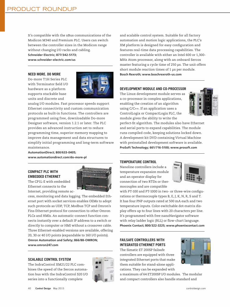
PRODUCT ROUNDUP
40 Control Design May 2015 controldesign.com
It’s compatible with the xBus communications of the
Modicon M340 and Premium PLC. Users can switch
between the controller sizes in the Modicon range
without changing I/O racks and cabling.
Schneider Electric; 877/342-5173;
www.schneider-electric.com/us
NEED MORE. DO MOREDo-more T1H Series PLC
with Terminator field I/O
hardware as a platform
supports stackable base
units and discrete and
analog I/O modules. Fast processor speeds support
Ethernet connectivity and custom communication
protocols as built-in functions. The controllers are
programmed using free, downloadable Do-more
Designer software, version 1.2.1 or later. The PLC
provides an advanced instruction set to reduce
programming time, superior memory mapping to
improve data management and data structures to
simplify initial programming and long-term software
maintenance.
AutomationDirect; 800/633-0405;
www.automationdirect.com/do-more-pl
COMPACT PLC WITHEMBEDDED ETHERNETThe CP1L-E with embedded
Ethernet connects to the
Internet, providing remote ac-
cess, monitoring and data logging. The embedded Eth-
ernet port with socket services enables OEMs to adopt
such protocols as UDP, TCP, Modbus TCP and Omron’s
Fins Ethernet protocol for connection to other Omron
PLCs and HMIs. An automatic-connect function con-
nects instantly over a default IP address to a switch or
directly to computer or HMI without a crossover cable.
Three Ethernet-enabled versions are available, offering
20, 30 or 40 I/O points (expandable to 160 I/O points).
Omron Automation and Safety; 866/88-OMRON;
www.omron247.com
SCALABLE CONTROL SYSTEMThe IndraControl XM21/22 PLC com-
bines the speed of the Sercos automa-
tion bus with the IndraControl S20 I/O
series into a functionally complete
and scalable control system. Suitable for all factory
automation and motion logic applications, the PLC’s
XM platform is designed for easy configuration and
features real-time data processing capabilities. The
controller is available with either an Intel 600 or 1,300-
MHz Atom processor, along with an onboard Sercos
master featuring a cycle time of 250 µs. The unit offers
short module reaction times of 1 µs per module.
Bosch Rexroth; www.boschrexroth-us.com
DEVELOPMENT MODULE AND CO-PROCESSORThe Linux development module serves as
a co-processor in complex applications,
enabling the creation of an algorithm
using C/C++. If an application uses a
ControlLogix or CompactLogix PLC, the
module gives the ability to write the
perfect-fit algorithm. The modules also have Ethernet
and serial ports to expand capabilities. The module
runs compiled code, keeping solutions locked down.
A development kit DVD containing Virtual Machine
with preinstalled development software is available.
ProSoft Technology; 661/716-5100; www.prosoft.com
TEMPERATURE CONTROLNanoline controllers include a
temperature expansion module
and an operator display for
connection of two RTDs or ther-
mocouples and are compatible
with PT-100 and PT-1000 in two- or three-wire configu-
rations or thermocouple types B, E, J, K, N, R, S and T.
It has four PNP outputs rated at 500 mA each and two
temperature inputs. Color-switchable dot-matrix dis-
play offers up to four lines with 20 characters per line.
It’s programmed with free nanoNavigator software
with relay ladder logic (RLL) or flow-chart language.
Phoenix Contact; 800/322-3225; www.phoenixcontact.com
FAILSAFE CONTROLLERS WITHINTEGRATED ETHERNET PORTSThe Simatic ET 200SP failsafe
controllers are equipped with three
integrated Ethernet ports that make
them suitable for stand-alone appli-
cations. They can be expanded with
a maximum of 64 ET200SP I/O modules. The modular
and compact controllers also handle standard and
CD1505_39_42_ROUNDUP.indd 40 5/4/15 11:30 AM

controldesign.com May 2015 Control Design 41
failsafe distributed applications requiring fast, down-
stream local discrete control for up to 128 I/O devices.
They integrate with and offer the same functions as
the Simatic S7-1200 and S7-1500 controllers, including
password protection against unauthorized reading out
and modification of program blocks. System diagnostic
information is displayed uniformly and in plain text in
the TIA portal, HMI and Web server.
Siemens; www.siemens.com
ADD-ON INSTRUCTIONSSigmaLogic, a new Sigma-5 servo option
that can be connected to Rockwell PLCs
with add-on instructions (AOIs), allows
users to control Sigma-5 Servopacks
within a Rockwell RSLogix5000 program.
The AOIs are compatible with all Com-
pactLogix and ControlLogix PLCs using
RSLogix5000 software v17 and above. It
can be used in conjunction with LogicWorks. It also
contains all of the key features of Sigma-5, such as
a tuningless mode that adjusts automatically for
up to 20:1 in load-to-rotor inertia mismatch, allow-
ing a smaller motor and reduced gearing, vibration
suppression that reduces noise during operation and
20-bit absolute encoders.
Yaskawa; 800/927-5292; www.yaskawa.com
CONTROL PLATFORM WITH SINGLE POINT OF CONNECTPACSystems High Availability with Profinet provides
a single point of connect for system configuration. All
remote I/O nodes can be configured from one central
location. With built-in Ethernet switches and built-in
media conversion, the technology provides for point-
to-point plug-in connectivity. Users can employ their
cable of choice on a node-by-node basis based on the
environment and distance and can conduct system
maintenance without taking the system offline. They
also can schedule device checking, such as a valve not
opening correctly based on flow commands, without
taking the entire pipeline control down.
GE Intelligent Platforms; www.geautomation.com
ON-MACHINE CONTROLLERSIMPLIFIES SYSTEM ARCHITECTUREThe Allen-Bradley Armor Guard-
Logix PAC can be installed directly
on-machine. It is IP67-, SIL 3, PL(e)-,
CAT 4-rated with 4 MB of applica-
tion code storage space with two full-featured Eth-
ernet/IP device-level, ring-capable connections. The
unit provides access to the controller-mode switch,
USB port, SD card and power-supply switch, along
with 24-Vdc power pass-through to supply power
to other On Machine products. This feature allows
power to be routed from one machine device or
module to another, eliminating the need for a power
supply for each device and simplifying the overall
system architecture.
Rockwell Automation; www.rockwellautomation.com
HIDEAWAY PLCFX3S battery-less PLC for space- and
cost-conscious applications requiring
up to 30 I/O includes integrated ac
power supply, maintenance-free EE-
PROM memory and built-in USB port
for the programming communication
function. This enables high-speed
communication at 12 Mbps, built-in positioning
control and integrated real-time clock. Program-
ming is via GX Works2 or GX Works2 FX.
Mitsubishi Electric; 847/478-2100; www.meau.com
ALL-IN-ONE PLC, HMI AND I/OThe Vision430 compact PLC
has an integrated landscape
and 4.3-in color touchscreen.
The touchscreen and five func-
tion keys are housed in a flat
fascia unit with an IP66/IP65/
NEMA4X rating, making the device suitable for in-
dustries with spray-down requirements. The control-
ler offers onboard I/O configuration, which includes
digital, high-speed and analog I/O, with options for
temperature and weight measurement. Time-based
and immediate interrupt support allow for use in
rapid-response applications such as packaging ma-
chines. Built-in recipe capabilities are supported by
data tables, which store the parameters required to
control a specific process.
Unitronics; www.unitronics.com
CD1505_39_42_ROUNDUP.indd 41 5/4/15 11:30 AM

PRODUCT ROUNDUP
42 Control Design May 2015 controldesign.com
PLC WITH FIELD WIRING-READY I/O TERMINALSThe EZWire1616 PLC offers
integrated, field-wiring-ready
I/O terminals. It provides
every digital and analog I/O
point with its own power (24 V or 5 V) and 0 V on a
three-level screwless terminal. Every sensor and
actuator in the control system can be wired directly to
the PLC without requiring additional screw terminal
blocks and wire harnesses. The controller uses the
company’s SmartTILE-Fx CPU. It supports full-floating-
point computation, nonvolatile FRAM, flash file system,
battery-backed RTC, Ethernet, RS-232, RS-485, digital
I/O, 12-bit Adc, 4-20 mA DAC, PWM, stepper controller,
and industry-standard Modbus RTU and TCP protocols.
Triangle Research International; www.triplc.com
SIMPLER SAFETYSC26-2 programmable safety
controller uses safety function blocks,
Boolean logic functions and a user-
friendly programming environment
to create safety control logic. It has 26
input terminals and two redundant,
solid-state safety outputs to monitor e-stop buttons,
rope pulls, interlock switches, safety light curtains
and other input devices. Free configuration software
has pre-configured safety function blocks, a ladder
logic diagram, and text-based summary of the input
device and controller output settings.
Banner Engineering; 888/373-6767;
www.bannerengineering.com
CAN BE TAKEN TO EXTREMESAC500-XC PLC is protected
against extreme conditions,
eliminating the need for sophis-
ticated protective enclosures.
The operating range is -30 ºC to
70 ºC, with reliable system start-
ups as low as -40 ºC. Circuit boards are conformally
coated to protect against high humidity levels, and
it has extended immunity against atmospheres with
corrosive gases. Vibration and shock can be tolerated,
with accelerations up to 4 G from random vibrations up
to 500 Hz, or 2 G from sinusoidal vibration. It also offers
extended EMC protection.
ABB; 262/780-3000; www.abb.com/plc
A LOT IN ONEAKD PDMM combines a multi-
axis motion controller, complete
IEC61131-3 soft PLC, EtherCAT
master and AKD servo drive in
one compact package to reduce
panel space and simplify wiring
and integration, while increasing
f lexibility, scalability and perfor-
mance. In addition, the device is
fully programmable through KAS Integrated Devel-
opment Environment, and its solution is scalable
from one axis to 128 axes with one controller.
Kollmorgen; 540/633-3545; www.kollmorgen.com
PAC WITH CAN/J1939 INTERFACEThe SmartPAC now supports
high-speed controller area
network (CAN) and SAE J1939
protocols. The built-in interface
provides a direct connection to
the CAN bus without requir-
ing an external converter. The
PLC can be used to control and
monitor CAN/J1939 devices as part of a machine or
process control application, log data and perform
statistical analysis. It can support as many as 16
different protocols simultaneously, thus providing
solutions for a range of applications, including trans-
portation and generator and battery monitoring.
SoftPLC; 800/softplc; www.softplc.com
GAP FILLERProgrammable and modu-
lar PCU Safety Control
Unit bridges the gap in
technology between
traditional safety relays
and PLC systems for
safety device integration
for machinery builders,
rebuilders and users. PCU/1 main control unit is
modular with 14 expansion modules, has up to 128
inputs, 16 dual-channel safety outputs and 16 status
outputs. An available, integrated PCU/1 main unit
has PCUEU/1 for adding multiple safety devices inte-
gration for switches, mats, edges and bumpers. It’s
certified up to CAT 4 SIL CL 3 SIL 3 Ple safety level.
Tapeswitch; 800/234-8273; www.tapeswitch.com
CD1505_39_42_ROUNDUP.indd 42 5/4/15 11:31 AM

FOR THOSE WHO like to take things slow, at least in
the beginning, technology has the answer: a soft starter.
These devices bring motors up to speed in a controlled
fashion, allowing machines to get going without a jolt.
That saves mechanical wear and tear and could save
money in other ways.
Soft starters work by temporarily limiting power
available to a motor, thereby allowing for a more
leisurely start. That can lead to smoother machine
startup and better overall plant operation by avoiding
line voltage dips, says Stan Komander, product man-
ager for soft starters at ABB Baldor (www.baldor.com).
However, before deciding on a soft starter, it’s im-
portant to ask a basic question: Why get one? Consider
a scenario in which a protective device trips during a
motor’s start, and the motor has trouble getting up to
speed for an unrelated reason: insufficient line power
or undersizing. It might seem that the answer would be
to go with a soft starter, but that would be a mistake,
says Komander. “The soft starter will only starve the
motor of necessary current,” he says. “It will only pro-
vide less power to start. So if the motor is not starting
across the line, well, the soft starter will not help.”
Soft starters can be the right solution to avoid pay-
ing a penalty and to keep a plant running, Komander
adds. Utilities may have a tiered pricing structure, and
users pay extra for exceeding a set current limit.
As for smoother plant operation, visual indica-
tions of motor startup may be seen in lights dimming
because of a line voltage dip brought about as current
rushes in. That drop can be as much as 40%, enough
to cause problems with protective devices and control
circuits. A soft starter can avoid this problem by re-
ducing initial motor voltage to a lower value, such as
30%. That will then be ramped up over a user-selected
period of time until full voltage is reached.
ABB Baldor’s soft starters use silicon-controlled
rectifiers (SCRs) with two per power phase. The SCRs
only conduct during part of the electrical power cycle,
which has the effect of reducing average voltage and
leads to a soft start. Hence, the motor accelerates
without sudden and abrupt changes, so there are no
mechanical jolts and jerks, Komander points out.
It’s important to properly size a soft starter and
match it to the application, says Nichole Angiola, prod-
uct manager for soft starters at Eaton (www.eaton.com).
A longer ramp time means that the SCRs are being used
longer, which creates heat and potentially damages
them. Getting that sizing right involves paying attention
to motor parameters that are sometimes overlooked.
“It is recommended to size the soft starter by the
motor full-load Amps current, not the power rating,”
Angiola says.
Another factor to consider is the application. Loads
such as pumps present particular problems, since
turning a pump on or off can lead to what is called a
water hammer effect. As the name implies, the start-
ing or stopping of water flow can act like a hammer,
which can rattle plumbing and lead to disaster. For
that reason some soft starters have special algorithms
that eliminate this effect and thereby extend the life
of pumps and other components, Angiola says.
Starts per hour is another concern. “Soft starters
are rated for a certain number of starts per hour,” says
Angiola. “If the application requires more, then the
soft starter must be sized appropriately to eliminate
premature SCR failure.”
Joe Kimbrell, product manager of drives, motors and
motion control at AutomationDirect (www.automation-
direct.com), warns that, if the speed of a motor must be
varied, then a soft starter is not a fit. But if the applica-
tion speed is constant, then the payoff to taking things
slowly at the beginning can be substantial.
Take the case of a loaded horizontal conveyor, Kim-
brell says. A great deal of torque is needed initially, but
not nearly as much when everything is up to speed.
Thus, the motors may only be lightly loaded during
normal operation. However, no matter the load, those
motors will consume the same internal, or magnetiz-
ing, current, and it is here that an intelligent soft start-
er can cut energy consumption by as much as 10%.
“What the soft starter does is lower the voltage to
the motor, lowering the magnetizing current, and sav-
ing money and energy,” Kimbrell says.
When smoother operation is desired, the key is to
look at a motor’s voltage and full load current. Voltage
is straightforward, but current can be more involved,
according to Kimbrell. A soft starter can be rated for
several different currents based upon the application.
A longer programmed ramp time results in a lower al-
lowable current due to heat buildup in the starter.
controldesign.com May 2015 Control Design 43
The big easy-does-it
Getting that sizing right involves paying attention to motor parameters that are sometimes overlooked.
by Hank Hogan, contributing editor
AUTOMATION BASICSHank Hogan • contributing editor • [email protected]
CD1505_43_AUTOBASICS.indd 43 4/27/15 5:11 PM

THE CTP SERIES solenoid locking safety switch from
Euchner can be used to monitor the position of mov-
able machine guarding by means of inductive coding.
These safety systems are designed for use in areas
where tamper-resistant safety is required. The CTP
features a narrow pro� le, thermoplastic housing, an
inductive read head with integrated evaluation mod-
ule and a digitally coded actuator.
The safety switch CTP combines electromechanical
safety-switch-operated guard locking or guard-lock
monitoring with transponder-coded safety engineer-
ing. The transponder technology allows a single
CTP to achieve Category 4 PLe, according to EN ISO
13849-1, without additional fault exclusion. “Many of
our safety switches have the integrated evaluation
built-in,” explains Mark Czapla, electrical engineer,
Euchner USA. “It doesn’t require external modules.
Coming out of the switch, you have two safety PNP
signals, similar to a light curtain. With this switch,
you can chain up to 20 switches together and retain
PLe and Category 4, with a single output connection to
a safety PLC or safety system control.”
The CTP also exceeds the requirements in EN ISO
14119 for a Type 4 switch with a high coding level. It’s
designed for applications in which a high performance
level and a locking force of up to 2,500 N are required.
“Anybody who has any of our TP or STP series safe-
ty switches and who requires multiple switches on a
door or a guard can put this on instead and have the
same level of protection using this single item,” says
Czapla. “One CTP guard can replace two of the others.
The CTP is designed for any type of people protection
where you have stored energy hazards, speci� cally
anywhere you have a switch, and you want it to be
very dif� cult to bypass.”
The CTP is equipped with a diagnostic function,
and an LED indicator is integrated on the front panel
so the device status is immediately apparent. With
the CTP, it’s also possible to connect monitoring
outputs and a diagnostics output directly to the PLC.
Depending on the version, the CTP is also suitable for
direct connection to safe control systems or for the
series connection of up to 20 devices.
“The switch is only going to respond to the actuator
to which it was installed,” explains Czapla. “You can’t
just use any mechanical switch. It’s much more dif� -
cult to bypass. The new design of the head is different
too, in that it will work in all four directions for the
actuator. It’s a little more forgiving. Many years ago,
they created a part
number for each
of the four direc-
tions. You’d need
four times as many
part numbers. It’s
a bookkeeping or
an inventory issue.
Now you don’t
have to do that.
You can put the
actuator in any of
the four directions,
and you don’t even
have to rotate it.”
The narrow
design of the CTP
makes possible
straightforward
and space-saving
mounting on the
safety guard. The
plastic housing
with metal head
and IP69K protec-
tion are designed
to give the CTP ap-
plication � exibility.
“It’s Unicode,” says Czapla. “It could be used in ma-
chine tools, grinders, processing robotics and all kinds
of dangerous machinery you want to keep employees
away from while it’s running. Unicode has been on all
of our RFID safety switches for years. The IP69K rat-
ing means it can be used where you have food-grade
applications you need to wash down. It’s made to
withstand the washing and harsh chemicals.”
Technical speci� cations include:
• reinforced thermoplastic housing
• environmental protection IP69K
• ambient operating temperature -20 to 55 °C
• operating voltage 24 Vdc +/- 15%
• current consumption 400 mA
• M23 or M12 connectors
• high-locking forces up to 2,600 N (584 lb)
• dual PNP safety outputs
• switching current 50 mA
• short-circuit-protected
• solenoid
• mechanical or electrical locking.
44 Control Design May 2015 controldesign.com
Tamper-resistant safety
FOR MORE INFORMATIONCall 866/547-7206, email [email protected] or browse to www.euchner-usa.com/safetyctp.asp.
EXCLUSIVE
CD1505_44_EXCLUSIVE_Euchner.indd 44 4/27/15 5:12 PM

controldesign.com May 2015 Control Design 45
EXCLUSIVE
THE UNIVERSAL PANEL Meter (UPM) series is the
culmination of 40 years that Dr. Otto Fest, president
and owner of Otek, has dedicated to current loop
power. The UPM includes automatic tricolor alphanu-
meric display and � eld con� gurability for analog and
digital inputs, data logging and control.
“In 1974, I started tinkering for a customer who
asked me to replace an old meter,” says Fest. “My � eld
was solid-state electronics design, and I was intrigued
by the amount of energy wasted in the current loop.
I came up with the � rst LCD loop-powered meter in
1974; that had a 12-V burden.”
It wasn’t until a few years ago when Fest came
across some high-ef� ciency LEDs and some nanotech-
nology that allowed him to develop the New Technol-
ogy Meter (NTM) and UPM series, with tricolor LEDs
and looped power.
All UPM models use the same patented technology.
The UPM series’ features include automatic signal fail
detection, indication and isolated serial transmission
with run-time stamp and unit ID, isolated retransmis-
sion (4-20 mA) and universal power input (5-32 Vdc
and 90-265 Vac) or powerless (signal power). The UPM
also offers math functions such as x-y tables, poly-
nomials and log/antilog functions. UPM signal and
external power series also feature isolated serial USB,
RS-485 or Ethernet μSD memory card to 32 GB, four
open collector transistors per channel and four SPDT
relays per channel.
The UPM can measure analog and digital signals,
serve as a slave display or message center with SCADA,
DCS or PLC, and it can be used as a controller or paper-
less recorder. “It can be modi� ed via the serial port to
perform any options originally selected,” Fest explains.
“That’s where our con� gurator comes into play. It au-
tomatically con� gures the part as per your selections,
and it provides pricing and a user’s manual customized
speci� cally to the part number that you enter.”
The units include Otek’s Powerless technology, which
means units don’t require any power other than what
the signal can produce, just like analog meters, which is
typically 10-80 mW per channel. These options cannot
drive relays or analog outputs, but they can drive the
isolated open collector transistors. “Using the Power-
less technology, when the unit detects a lost signal,
immediately a distress message is transmitted via the
serial port to supervisory equipment and the display,
for about 20-30 seconds,” explains Fest.
The UPM is ideal for applications with an isolated sig-
nal that needs to be monitored. “If you have a multitude
of parameters or machinery you need to control, your
best bet is to go with a SCADA system,” advises Fest. “In
a nuclear facility, for example, where you’re monitoring
Volts, Watts, Amps and/or Hertz, on a three-phase sys-
tem, the operator can be overwhelmed by the amount
of information he has to look at and record.”
The UPM can monitor and control up to � ve isolated
parameters. “They can be independently assigned to
control a process or be a slave,” he explains. “You can
override the relays and analog output via the serial
communications. It gives the operator more freedom,
but it gives the engineer more choices to place the
UPM in the factory, instead of one multifunction dis-
play in a control room that is remote.”
Fest also considered integration with existing
equipment when he developed the UPM. “We made a
unit that can be customized to replace form, � t and
function of existing units in the � eld and customized
to the same wiring that the plant or installation might
already have. The customer can replace one unit at a
time or all 500 units at once.”
Each UPM unit uses 1% of the energy required by a
digital meter, says Fest. “The lowest we can go in pow-
er consumption today is 10 mW per channel, so the
customer doesn’t have to redesign its power source.
They don’t have to shut down the system to replace it
with our unit. As long as your signal can generate 10
mW, you can replace any analog with the UPM or NTM.
That’s why we tell our customers, ‘If we don’t have it,
we’ll make it.’”
The power of confi gurability
FOR MORE INFORMATIONCall 520/748-7900, email [email protected] or browse to www.otekcorp.com.
CD1505_45_EXCLUSIVE_Otek.indd 45 4/27/15 5:13 PM

46 Control Design May 2015 controldesign.com
EXCLUSIVE
ENCLOSURE PURGING SYSTEMSeliminate the possibility of
combustible gases within sealed,
pressurized enclosures in hazard-
ous areas by ensuring their atmo-
sphere is essentially nothing but
the purge gas, typically nitrogen.
Flow and pressure measurements
are used to determine when the
atmosphere is suitably purged,
typically clearing an interlock that
allows power to the enclosure.
“Our customers like the X-Purge
control we designed 15 years ago,”
says Mike Hadaway, general man-
ager, Daisy Data Displays. “We in-
corporated their comments when
we redesigned it using new tools
and techniques and improved it
based on what we’ve learned from
them since then. The new version
works on multiple cabinets and
complex cabinets. It’s smaller,
modular and easier to install, and
it can directly replace the origi-
nal version using adapters on the
original cutouts.”
The 9216 consists of inlet and
exhaust modules. The redesign
shifts the purge gas pressure and
� ow control from the inlet module
to the exhaust module, managing
the � ow rate inside the enclosure.
Controlling on the basis of exhaust
rather than inlet � ow and pres-
sure, “we can detect and measure
any leaks and meet requirements
for IEC, Ex and Atex, as well as
NEC and NFPA,” Hadaway says.
The new version allows mul-
tiple exit modules—initially
up to four—to be paired with a
single inlet module. With multiple
exhaust modules, a single inlet
module can feed multiple supply
inlets through tubing and control
the atmosphere of multiple and
complex cabinets.
“Very large enclosures with
odd shapes and cavities may have
pockets where the atmosphere is
stagnant,” says David “Avi” Shefet,
president, Daisy Data. “Using
multiple exhaust modules with
a single supply module reduces
purge time and the complexity of
the purge system.”
Daisy’s modular design allows
the system con� gurator to add
more exhaust and inlet modules to
increase air� ow, reducing internal
pressure and purge time. “The
9216 X-purge controls are fully
automated and require no human
intervention to purge a system,”
says Ray Ravida, R&D engineer,
Daisy Data. “Most applications
realize a substantial cost bene� t
as a result of being able to moni-
tor multiple enclosures with one
purge control while automating
the monitoring process.”
Purging is demand-based. After
the cabinet is completely purged,
the exhaust modules shut off to
maintain gas pressure where the
original system would continue to
demand gas. If leaks are not exces-
sive, this conserves gas, and, if the
leakage rate is high, the system
lets you know.
The new version also provides
more frequent and detailed purge
cycle and data reporting, allow-
ing users to monitor and manage
system performance better and to
diagnose issues if and when they
occur. Even in con� gurations with
multiple enclosures, all inlet and
outlet modules communicate back
through one centralized reporting
process to identify the pressure in
each of the multiple units.
The redesign replaced but-
tons and LEDs with a keypad
and LCD readout. A two-line-by-
20-character display provides
information about the status of
the purge control, including time
to complete the purge cycle, pres-
sure � ow, enclosure size, histori-
cal data, failure mode and more.
“Pressure, � ow and temperature
data is collected, and you can
see it at any time, as well as any
problems,” says Shefet. “All data is
accessible through USB, as well as
by network connections.” Interlock
relays are provided for ac power
and 12 data points.
“This 9216 Series X-purge control
is a great example of how Daisy de-
velops products in direct response
to end-user needs and preferences,”
Shefet adds. “As applications be-
come more demanding, environ-
ments more challenging, data needs
become more complex, customers
want industrial computing solu-
tions that that can � ex to meet their
needs. The 9216 X-purge control is
the ultimate in � exibility.”
Purge control: more safety, less gas
FOR MORE INFORMATIONCall 717/932-9999, email [email protected] or browse to www.makeitdaisy.com.
FOR MORE INFORMATION
CD1505_46_EXCLUSIVE_DaisyData.indd 46 4/27/15 5:15 PM

WE’VE BEEN USING resolvers to track motor-shaft
position in the CNC machines we build for years. And
no one has asked, so we’ve never considered changing
that technology. But now a customer has requested
we also utilize encoders. While the variety of en-
coder types—capacitive, magnetic, optical—is pretty
straightforward, we’re having some discussions as we
try to understand the communication protocols avail-
able and which direction to go. Can I replace a resolver
with a sin/cos encoder? What about Hiperface, EnDat,
SSI? If the application dictates the encoder or resolver,
does the device dictate the communication protocol?
ANSWERS
Match motor feedbackThere are a few things to look at when switching to a
new feedback device. When switching from a resolver
to an encoder you need to make sure that the encoder
can survive in the applications environment. Resolvers
are much more robust relative to high temperature and
shock. Next, I would look at required resolution. Resolv-
ers are typically 12-bit. If you are switching to an en-
coder with higher resolution than this, make sure that
the input frequency of your controls can digest all of
the pulses/revolution relative to the applications rpm.
Another factor to consider is cost. The protocols you
called out typically are associated with absolute encod-
ers vs. incremental encoders. Absolute encoders can be
much more expensive, especially if the quantities being
ordered are fewer than 1,000. Finally, which protocol
you choose to go with can be primarily dependent on
the motor and drive that are being offered. Different
drive manufacturers may choose Hiperface over EnDat
or may offer both as an option. You need to make sure
that the protocol you choose for the motor feedback
will be a match for your selected controls.
Jeff Nazzaro, gearhead and motor product manager,
Parker Hannifin Electromechanical Automation NA,
www.parker.com/emn
ResolutionThe basic question to answer first is whether you want
to use incremental or absolute angular information.
Incremental is more common for speed control, while
absolute is favorable for positioning. A sin/cos unit
would be preferred if you need very high resolution
(>16-bit steps; better than 0.005°), because the output
signals can be interpolated by the controller, but the
electronics will add to costs on the controller end.
Because you have used a resolver so far, most likely
the resolution of any type of A-quad-B pulse output
encoder will do the job. TTL, push-pull or differential
line-driver outputs are most common, and what to
choose depends on the counter card of the controller
available plus EMC considerations. For absolute encod-
ers, there are some different considerations. While all
of the above-mentioned interfaces (Hiperface, EnDat
and SSI) can do the job, two of the three leave you
with single sources for the encoders due to the patent
situation. SSI is a very good option, because it’s easy
to implement, even with simple control systems; it’s
sufficiently fast (can run with up to 2 MHz clock) and
offers basic error-checking features (multiple trans-
mission, line break/short detection, parity or CRC
features). You will also find hybrid units that provide
SSI and incremental outputs to combine dynamic
speed control with absolute positioning. BISS would
be another option, but it will leave you with a limited
number of encoder suppliers, as well. In terms of costs
and robustness, a magnetic sensing system is recom-
mended. The modern systems don’t have issues with
long cycle times and low accuracy anymore. Depend-
ing on your current resolver specs/target specs, you
might even end up with lower overall costs.
Christian Fell, VP motion & position sensors,
Posital-Fraba, www.posital.com
TTL-compatibleEncoders these days typically have what is called
a standard ET7272 output line driver, which can be
configured as NPN or PNP type outputs. Furthermore,
encoders can be specified to have 5-V output (TTL-
compatible). What you will want to specify for your
CNC machine is whether the encoder needs to be
absolute or incremental. In terms of communication
protocols, you can now find encoders that have SSI,
ProfiBus, DeviceNet and even Ethernet I/P communica-
tions, so it all depends on your application.
Vikram Kumar, sales application engineer,
Autotech Controls, autotechcontrols.net
More than robust encodersIn general, resolvers are more robust than encoders;
they tolerate shock, vibration and temperatures better
than most encoders. So you may want to have your
customer take some responsibility for the reliability
of the encoders on the machine.
controldesign.com May 2015 Control Design 47
[email protected] REAL ANSWERS
Which encoder communication protocol?
CD1505_47_49_REALANSWERS.indd 47 4/27/15 5:17 PM

That said, encoders offer more features, higher
resolutions and greater accuracy, so there are good
reasons to use them. Given the machine environment,
you may want to consider some of the optical inter-
faces to keep the noise problems to a minimum.
Rick Halstead, president,
Empire Magnetics, www.empiremagnetics.com
Not created equalThe answer to your question is not straightforward.
First, what protocols can your CNC controller accept as
motor feedback? There are many data protocols that
will work for your application. Multi-turn encoders are
available for all of the interface types you listed, but
there are also networked encoders—DeviceNet, Profi-
bus, Ethernet/IP and Profinet, just to name a few. What
resolution does your system require? Multi-turn encod-
ers can provide 12-bit resolution per turn or 13-bit or
16-bit; you get the idea. All of these encoders will pro-
vide you with absolute position feedback. The choice
will be determined by factors that you will need to
examine further—resolution requirement, update rate
of position and available interfaces for your controller.
Be aware that the most durable and reliable posi-
tion feedback is the resolver you are already using. So
when you select an encoder make sure the encoder
you select can meet the mechanical, electrical and en-
vironmental requirements of the system. All encoders
are not created equal.
Matthew Tellier, product manager—motion control,
Advanced Micro Controls (AMCI), www.amci.com
Solid mechanicsResolver outputs are inherently absolute; however, you
may or may not require an absolute output. It’s com-
mon practice to use an incremental encoder for speed
(say, for spindle speed control) and an absolute en-
coder for position (tool position would be an example).
Resolution and precision for optical encoders exceed
those of resolvers, so your mechanics need to be solid;
otherwise the encoders will reveal the errors (back-
lash or other non-linearities in your system).
Regarding protocols, for incremental encoders, A
and B in quadrature with complements and an option-
al index are very standard. This gives you a choice of
a wide variety of standard controllers. Most industrial
systems have moved to 24 V as the standard supply
voltage, and it is recommended to use this voltage
and to take advantage of a differential output, as that
combination gives you the best noise immunity. For
absolute encoders, I agree that SSI is the most univer-
sal interface and again gives you the widest selection
of controllers to work with.
Scott Orlosky, manager, business development,
BEI Sensors, www.beisensors.com
Wrapped resolverWhat type of machine is this? How big a project are you
planning? Is this a total redesign, or do you hope to just
swap an encoder for a resolver? Most sin/cos encoders
are not strictly absolute. They will have 512, 1,024 or
2,048 cycles per revolution, so they are not the same
as a resolver with one cycle per revolution. An encoder
would be more like a two-speed resolver. One set of out-
puts would be one cycle per revolution, and another set
would be 512 or 1,024 and so on. So you have some work
to do, even if this most basic conversion is planned.
You might also consider just leaving the resolvers in
place for speed control and wrapping a position loop
around them using a set of linear encoders on the ways.
Not knowing the application, this of course would not
work for a rotary table or spindle speed/tapping control.
Bob Setbacken, LeineLinde product management,
Heidenhain, www.heidenhain.com
No perfect conversionThere is no perfect conversion from resolver output to
sin/cos encoder output. There are pluses and minuses to
every change in feedback, which has to be designed-in
properly for a finely tuned system. The device used does
not dictate the communication protocol. The engineering
team manufacturing the machine decides on the overall
communication structure required for the most efficient
operation desired and monitoring of the machine. We
would need a lot more information on the actual ma-
chine requirements to help further in this discussion.
Greg Bova, motion business development manager,
Baumer, www.baumer.com
Controller drives protocolThe quick answer is yes. You can replace a resolver
with an encoder. However, it’s the subsequent elec-
tronics that will need changing, too. You mention a
CNC machine and Hiperface EnDat and SSI (protocols).
A lot depends on the controller you are using for your
48 Control Design May 2015 controldesign.com
[email protected] ANSWERS
While the variety of encoder types—capacitive, magnetic, optical—is pretty
straightforward, we’re having some discussions as we try to understand the communication protocols available and
which direction to go.
CD1505_47_49_REALANSWERS.indd 48 4/27/15 5:17 PM

CNC. There are a multitude of controllers
and a multitude of encoder inputs. In short,
make your controller choice, and then
choose the encoder protocol to suit your
controller. Then choose the encoder with
the correct protocol to suit your perfor-
mance requirements.
Howard Salt, business manager, encoder systems,
Renishaw, www.renishaw.com
Encoder-dominantThe short answer is that resolvers, like
encoders or rotary inductive sensors, can
be purchased with various output pro-
tocols. What is available will vary from
manufacturer to manufacturer. Over the
years, encoder technology has become
the dominant design for rotary feedback
devices. As a result, a manufacturer’s
encoder product lines typically offer a
wider variety of output protocols than a
resolver’s design. Selection of which rotary
feedback technology is used comes down
to price, performance and application
requirements. Resolvers have a reputation
for being able to offer high shock and vibra-
tion resistance.
Tony Udelhoven, vice president—sensors division,
Turck, www.turck.com
More flexible motionProtocol isn’t as important. Resolvers
are more passive and can be thought of as
analog in this scenario. The analog signal
is converted into a digital resolution (for
example, 16-bit). Resolvers used in ap-
plications can be replaced with a sin/cos
encoder, as long as the resolution is taken
into account or the number of counts per
encoder revolution is considered.
The more resolution there is within
the encoder, the more feedback informa-
tion about position and/or speed you can
evaluate in the control of the drive. Most
vendors of motors and drives have pre-
ferred communications protocols. Some of
these encoder communications protocols
are open, while others are proprietary. This
means that not all motors are compat-
ible with all drives. There are a few drives
available that encompass more protocols
and allow much more flexibility in motor
selection. Ultimately, the application dic-
tates if incremental, single-turn absolute or
multi-turn absolute encoders are needed.
The encoder communication protocol is
less important than well-sized motors and
encoder selection that is appropriate for
the application. Leveraging a more flexible
motion system as a whole can make re-
solver and encoder replacement challenges
much easier to solve.
Daymon Thompson, product specialist,
Beckhoff Automation, www.beckhoff.com
controldesign.com May 2015 Control Design 49
Advantech Automation . . . . . . . . . . . .17
Allied Electronics. . . . . . . . . . . . . . . . 6
AutomationDirect. . . . . . . . . . . . . . . 52
AVG Automation . . . . . . . . . . . . . . . . 2
B&R Industrial Automation . . . . . . . . .10
Baldor Electric . . . . . . . . . . . . . . . . .15
Banner Engineering . . . . . . . . . . . . . .21
Beckhoff Automation . . . . . . . . . . . . . 4
Daisy Data Displays . . . . . . . . . . . . . 37
Euchner . . . . . . . . . . . . . . . . . . . . . 35
ITS Enclsoures . . . . . . . . . . . . . . . . 28
Maple Systems . . . . . . . . . . . . . . . . 22
Omron Electronics . . . . . . . . . . . . . . . 8
Patlite . . . . . . . . . . . . . . . . . . . . . . . 7
Pepperl+Fuchs -PA Division . . . . . . . .16
Pepperl+Fuchs . . . . . . . . . . . . . . . . 25
Phoenix Contact . . . . . . . . . . . . . . . . 3
Pro-Face America . . . . . . . . . . . . . . 27
Siemens Industry. . . . . . . . . . . . . . . 12
Telemecanique . . . . . . . . . . . . . . . . 23
TRC Electronics. . . . . . . . . . . . . . . . 32
Unitronics. . . . . . . . . . . . . . . . . . . . 34
WEG Electric. . . . . . . . . . . . . . . . . . .31
Wieland Electric . . . . . . . . . . . . . . . .51
AD INDEX
PUBLISHING TEAM
GROUP PUBLISHER & VP, CONTENT
KEITH LARSON [email protected]
DIRECTOR OF CIRCULATION
JACK JONES [email protected]
SALES TEAM
northeastern and mid-atlantic regional manager
DAVE FISHER [email protected]
508/543-5172 Fax: 508/543-3061
24 Cannon Forge Dr.
Foxboro, Massachusetts 02035
MIDWESTERN AND SOUTHERN REGIONAL MANAGER
GREG ZAMIN [email protected]
630/551-2500 Fax: 630/467-1124
1501 E. Woodfield Rd., Suite 400N
Schaumburg, Illinois 60173
WESTERN REGIONAL MANAGER
LAURA MARTINEZ [email protected]
310/607-0125 Fax: 310/607-0168
218 Virginia, Suite 4, El Segundo,
California 90245
DIGITAL SALES SPECIALIST
JEANNE FREEDLAND
805/773-4299 Fax: 805/773-0451
INSIDE SALES SPECIALIST
POLLY DICKSON [email protected]
630/467-1300 Fax: 630/467-1124
EXECUTIVE STAFF
president & ceo
JOHN M. CAPPELLETTI
cfo
RICK KASPER
vp, circulation
JERRY CLARK
vp, creative services, production
STEVE HERNER
REPRINTS
FOSTER REPRINTS www.fosterprinting.com
JILL KALETHA
866-879-9144 ext. 168
is the only magazine exclusively
dedicated to the original equipment
manufacturing (OEM) market for
instrumentation and controls—the
largest market for industrial controls.
1501 E. Woodfield Rd., Suite 400N
Schaumburg, Illinois 60173
630/467-1300
Fax: 630/467-1124
CD1505_47_49_REALANSWERS.indd 49 4/27/15 5:18 PM

This is the second part of a multi-part article. To read the
entire piece, visit www.controldesign.com/robotplc.
THE PROBLEM WITH master-slave integration of
robots is that it’s a point of pain for engineers, as they
continually must learn a new third-party software
package or attend a vendor training seminar to prop-
erly write software for the third-party devices. In an
industry that demands a great deal of time from a cus-
tom machine integrator, engineers simply don’t have
time to learn about a new third-party device.
This is a large deterrent for potential first-time us-
ers. They’re reluctant to try new vendors because of
the learning curve involved in understanding how the
slave device integrates and communicates with the
existing PLC system that’s designed into an automated
machine as the main controller. This pain level creates
additional costs in a project scope as engineers are
forced to learn new software devices, directly impact-
ing engineering time quoted on a project.
Over the past decade, fieldbus has advanced in shar-
ing software memory mappings between the master
PLC and third-party slaves. Today, the logic concept
still stands that the master PLC is written to sequence
the main control on the automated machines, as
the third-party slave devices have code written in a
non-standard ladder logic format. This is, however,
dependent on which kind of device is handling the
auxiliary process. In some cases, third-party devices
are written in structured-text language sets that must
be treated as stand-alone processes. These software
subsystems must be written to act independently of
the main PLC architecture. Therefore, the pain level of
learning, as engineers must learn how to write code in
these third-party devices that are often not coded in
the same way as the main PLC ladder logic.
This exchange of information is generally a single
bit level flag that is set in the main PLC from a ladder
diagram rung, which instructs the slave devices to go
or start the auxiliary process. At this time, the ladder
sequence in the PLC must wait for a confirmation bit
from the third-party device indicating its process is
complete. This is a low level of data exchange, and
extracted information is vague once its task is com-
plete. As automation and technology have evolved, the
need to share detailed information about third-party
process controls has become more demanding in
terms of preventing failures or logging statistical data
about a part in production. Because of simple mapping
concepts of the bit-level exchanges, it can be difficult
to extract the scientific data of actual results from
third-party processes to and from a PLC’s memory
mapping exchange only.
How do you change the mindset regarding third-
party control? With a robot controller, what if there
were a way to embed direct control of third-party
devices into PLC ladder logic? This type of control
methodology would be a different concept or approach
in a control scheme. By creating function blocks that
communicate with the robot controller directly in
ladder logic, it simplifies the integration handshaking
between multiple devices such as a PLC and a third-
party controller. If you could simply make the robot
move with a single ladder-logic function block, this
would solve all the issues of integration and eliminate
the frustrations of learning another software package.
Allen-Bradley PLCs from Rockwell Automation have
provided the ability to create control function blocks
called add-on instructions (AOIs), which allow third-
party vendors to create control or function blocks that
are imported into the PLC. However, not all AOIs are
created equal. Some AOIs have been created that try
to emulate the old-school integration concept. These
can make it easier to interact and integrate with a
robot controller, but code still has to be written in the
robot controller before the robot is instructed to move
via the PLC. How can vendor-provided AOIs take the
integration to the next level? This is done by chang-
ing the concept of that interaction to something that
simplifies the control of a robot so the PLC commands
the robot directly without the need to learn or write a
single line of code in the robot controller. It would be
a significant improvement to provide PLC program-
mers the ability to directly control their robots in an
integrated manner within the PLC software and se-
quence direct robot motion from within a ladder-logic
instruction block. This is exactly the approach that
we’ve taken with our RCX240 controller connected via
Ethernet/IP to an Allen-Bradley PLC.
Chris Elston is senior controls engineer at Yamaha Robotics.
Contact him at [email protected].
50 Control Design May 2015 controldesign.com
In some cases, third-party devices are written in structured-text language sets that must be treated as stand-alone processes.
Robot integration in the PLC—Part II
OEM INSIGHT Chris Elston • [email protected]
CD1505_50_OEMINSIGHT.indd 50 4/27/15 5:19 PM

safe
ty
Power in Safety
samos®PRO COMPACTProgrammable Safety Controller
45 mm Wide Housing16 Safe Inputs , 4 Safe Outputs
4 Configurable Safe I/O -25°C to +65°C
4 A Outputs
1 800 wieland (1-800-943-5263) | [email protected] www.wieland-safety.com/samosPROCOMPACT
samos ® PRO COMPACT programmable safety controller is the future. The 45 mm base modules can be expanded to a maximum of 116 safe inputs and 56 safe outputs. The samos ® PLAN5+ programming interface is available at no charge and uses freely configurable logic to meet the demands of your application. Its powerful simulation, documentation and testing tools facilitate wiring, commissioning and maintenance. The built-in Ethernet port saves space, can be used for remote programming, diagnostics and industrial communications.
Wieland - Safety - Samos PRO COMPACT 2.indd 1 4/15/2015 1:12:44 PMCD1505_FPA.indd 51 4/27/15 5:33 PM

You get MORE and MORE with C-more® HMI!
the #1 value in automationOrder Today, Ships Today!
* See our Web site for details and restrictions. © Copyright 2014 AutomationDirect, Cumming, GA USA. All rights reserved. 1-800-633-0405
Research, price, buy at: www.automationdirect.com/c-more
MORE MATH • New math functions allow you to create
custom formulas with constants or tag values
• The Math Keypad provides simple and complex operations including log, sine, and square root
MORE LOGIC • New tag combinations allow for
simple logic with multiple events
• Combine up to four diff erent tags to trigger actions based on logical results
MORE ACCESSIBILITY • The new Object Layer List Window shows
all the objects on the active screen and allows you to lock/unlock, hide/unhide objects or quickly select them for editing
• The Object Layer List also allows you to access individual objects in a group with-out ungrouping and has additional lists for hidden, locked or overlapping objects
• Recipe database that supports 99 recipe sheets, each with 1000 recipes of 256 possi-ble tags or values can now be modifi ed and saved on the fl y by the operator while the machine is running
• New menu options, customizable toolbars and updated graphics for improved ease of use
MORE ALARMING OPTIONS• Enhanced Alarm List off ers more options for
alarm customization
• New alarm fi lters allow for dedicated alarm summaries
* C-more EA9 Software Version 6.0 is only compatible with EA9 series hardware.
•
•
LESS COST• With software priced at $99.00 and hardware
starting at just $499.00, C-more is designed togive you one of the best costs of ownership,considering initial price, features, ease of use,reliability and free award winning technical support
* C-more EA9 Software Version 6.0 is onlycompatible with EA9 series hardware.
The new C-more EA9 software package delivers more functionality, more usability and more value to our popular C-more HMIs. This software is packed with features and upgrades designed to give you MORE for LESS!
The new C-more EA9 software package delivers more
C-more EA9Touch Panels
start at
$499.00!
EA9-T12CL 12” model shown priced at $1790.00
C-more 6.0 Softwareonly $99
C-more Remote HMI AppFor only $4.99 you can have remote access and control on the go! Available now in your Apple®
or AndroidTM app store.
1505-ControlDesign-CmoreEA9-MAG.indd 1 4/14/2015 11:12:50 AM
CD1505_FPA.indd 52 4/27/15 5:34 PM