p r o b l e ms 77 - creating web pages in your account –...
TRANSCRIPT

resistances. Combine resistors in parallel by adding their conductances. The wye-to-delta and deila- to-wye transformations are also an aid in reducing the complexi ty of a network.
PROBLEMS
2.1 Determine the current and power dissipated in the resistor in Fig. P2.1.
Figure P2.1
2.2 Determine the current and power dissipated in the res istors in Fig. P2.2.
20
12 V 0.5 S
Figure P2.2
2.3 Determine the voltage across the resistor in Fig. P2.3 and the power diss ipated.
Figure P2.3
2.4 Given the circuit in Fig. P2 A, find the voltage ac ross each res istor and the power dissipated in each.
5n
6 A 0.25 S
Figure P2.4
2.5 In the network in Fig. P2.S. the power absorbed by Rx is 20 mW. Find R,.
Figure P2.5
P R O B L E MS 77
• Short circuit Zero resistance, zero voltage; the current in the short is determined by the rest of the circuit.
• Open circuit Zero conductance, zero current; the voltage across the open terminals is determined by the rest of the circuit.
2.6 In the network in Fig. P2.6, the power absorbed by G.l is 20 mW. Find G, .
Figure P2.6
2.7 A model for a standard two D-cell flashlight is shown in 0 Fig. P2.? Find the power dissipated in the lamp.
1-n lamp
1.5 V
Figure P2.7
2.8 An automobi le uses two halogen headlights connected as e shown in Fig. P2.8. Determine the power suppl ied by the battery if each headlight draws 3 A of current.
12V
Figure P2.8

78 C H A PTE R 2 RE S I S T IV E C I RC UI TS
2.9 Many yea rs ago a siring of Christmas tree ligh ts was manufactured in the form shown in Fig. P2.9a. Today the lights are manufactured as shown in Fig. P2.9b. Is there a
good reason for this change?
: ®n------.,@--h-m-m~
(a)
: ¥ fn n~ ________ __ --'f (b)
Figure P2.9
2.10 Find 11 in the network in Fig. P2.IO
2mA
Figure P2.10
2.11 Find I I in the network in Fig. P2. !1
6mA
4mA
Figure P2.11
2.12 Find I I in the network in Fig. P2. 12
I I
6mA
Figure P2.12
2 mA
2.13 Find 11 and 12 in the ci rcuit in Fig. P2. 13.
S mA
4 mA 2mA
Figure P2.13
2.14 Find I] in (he ci rcu it in Fig. P2. 14.
I I
4 rnA
+
2mA
Figure P2.14
2.15 Find Ix in the circuit in Fig . P2. IS.
5 I,
LI.::x ___ -.4 ____ -!. ____ ..J 2 mA
Figure P2.15
2.16 Determine h in the ci rcu it in Fig. P2. 16.
6 kfl 3 I, 2 kfl 3 kfl
Figure P2.16

o 2.17 Find 10 and 'I in the c irc uit in Fig. P2.17.
SmA
4 mA
2mA
3 mA
Figure P2.17
2.18 Find 1.1"1 I,.. and ( in the network in Fig. P2 . IS.
3mA f ,
12 mA
+---.I'W'--t---{- +
j 4mA
f, 2 mA
Figure P2.18
2.19 Find VIxl in the c ircuit in Fig. P2.19.
a b c 0---{111,"--<>---4 + -
+ 4V -6V +
12 V 2V
d
Figure P2.19
2 .20 Find V;ul in the network in Fig. P2.20.
a b c
- 3V + - 2 V +
4V 12 V
e + 3V -
Figure P2.20
PROBLE MS 79
2 . 21 Find ViI> and V .. c in the circuit in Fig. P2.21.
2V
+
a b c ~-+---ANL--1-~+ -
+ 1 V -12V 3V
d
g - 2V + f - 1 V + e
Figure P2.21
2 .22 Find \t;", and v.:/ in the circuit in Fig. P2.22.
+ 6V
a b .-~MI~-+---{+ -
- 4V + 9V
c
12 V 6V +
e
Figure P2.22
SV
+
d
+ 3V
2.23 Given the c ircuit diagram in Fig. 2.23, find the following
voltages: \!;/ip \ill' ~C' V,li, ~'" Yoc. v,,;. 'if · ~b' and ~C'
8V
16 V
12V
Figure P2.23
12V
4V
2.24 Find V,IC in the c ircuit in Fig. P2.24.
a b .-___ Ml~-+--_<+ -
+ 4V -
3Vx 12 V
Figure P2.24
c
20V
14 V
+
v = 2V x
80 CHAPTER 2 RESISTIVE CIRCUITS
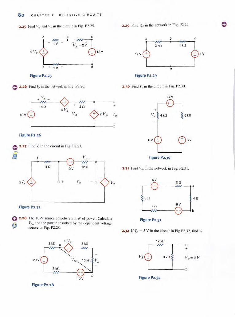
2.25 Find y,,,[ and Y,'c in the circui t in Fig. P2.25. 2.29 Find v,Jd in the network in Fig. P2.29. o a b c
a b c - 1V +
3 kO
4 V,. + 12 V 12 V 4V
e + 1 V d
Figure P2.25 Figu re P2.29
o 2.26 Find ~ in {he network in Fig. P2.26. 2.30 Find ~{ in the circuit in Fig. P2.30.
V,. + . -24 V
- + 0
40 4 V,.
+ 20 •
12V VA + 2 VA Vo 6 kO
Figure P2.26 6V + BV o 2.27 Find ~ in the circuit in Fig. P2.27.
iii Ix _ V ... I - Figure P2.30
L - +
40 12V 120
-j 21,. + Vo + V,
2.31 Find V:dJ in the network in Fig. P2.3l.
6V 20
a
30 40
Figure P2.27 60 9V
-+ b
0 2.28 The IO-V source absorbs 2.5 Il1W of power. Calculate ~ Vim and the power absorbed by the dependent voltage 'j£I source in Fig. P2.28.
Figure P2.31
2.32 If Vo = 3 V in the circuit in Fig P2 .32, find Vs.
2 V, 3 kO II
12 kO
20V V ba 10kO Vol"
~ + 5 kO
b 10V Figure P2.32
Figure P2.28
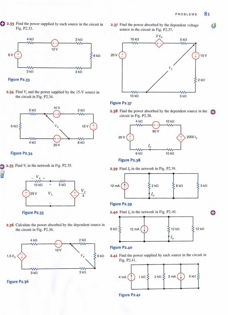
e 2·33 Find the power supplied by each source in the circui t in Fig. P2.33.
6 V
4 kfl 2 kfl r-~~----~+-r-----~--~
12 V
3 kfl 3 kfl
Figure P2.33
6 kfl
2.34 Find V, and the power supplied by the IS-V source in the ci rcuit in Fig. P2.34.
5 kfl 10V
'\-+ 6kfl
4 kfl 25V
Figure P2.34
Find VI in the network in Fig. P2.35.
_ Vx +
10 kfl + 5 kfl
25V
Figure P2.35
2 kfl
8 kfl
Vx 4
2.36 Calculate the power absorbed by the dependent source in the circuit ill Fig. P2.36.
4 kfl 2 kfl ~~~----~+ -'~~~~N--.
12V
P R OB L EMS 81
2.37 Find the power absorbed by the dependent voltage source in the circuit in Fig. P2.37.
2 Vx 10 kfl 5 kfl
20 V
2 kfl
10 kfl
Figure P2.37
3 kfl
2.38 Find the power absorbed by the dependent source in the 0 circuit in Fig. P2.38.
4 kfl
20V
6 kfl
Figure P2.38
Ix
10 kfl
2.39 Find 10 in the network in Fig. P2.39.
+ 2000 Ix
2 kfl 6 kfl 3 kfl
Figure P2.39
2 .40 Find 10 in the network in Fig. P2.40.
6kfl 12 kfl 12 kfl
Figure P2.40
1.5 V, 6 kO 2.41 Find the power supplied by each source in the circuit in Fig. P2.4I.
~--~~r---r--J
3 kfl 3 kfl
4 rnA 1 kfl 2 kfl 2mA 5 kfl
Figure P2.36
Figure P2.4'
82 CHAPTER 2 R E SIST I VE C I RC U ITS
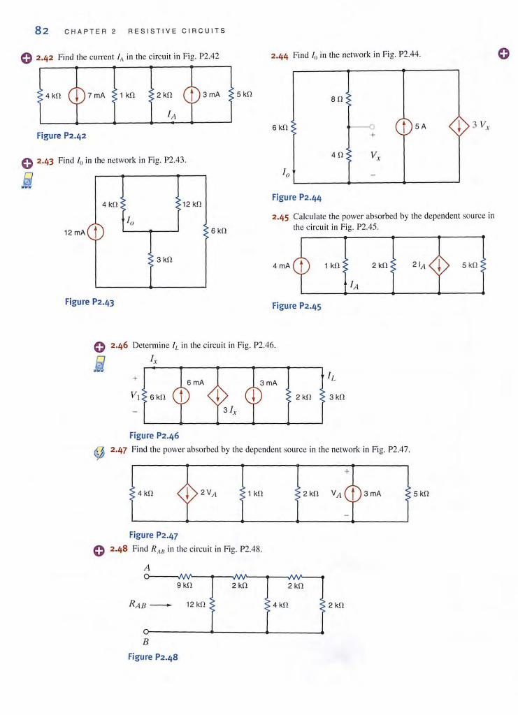
o 2·42 Find the current If\ in the circuit in Fig. P2.42
4 kf! 1 kf! 2 kf! 5 kf!
Figure P2.42
o 2·43 Find 10 in the network in Fig. P2.43.
9 -4 kf! 12 kf!
10 12 mA t 6 kf!
3kf!
Figure P2.43
2.44 Find 10 in the network in Fig. P2.44.
af!
6 kf! --0 t 5A j +
4f! V-'
-
Figure P2 .44
2.45 Calcu late the power absorbed by the dependent source in the circuit in Fig. P2.45.
4mA 1 kf! 2 k!1 5 k!1
Figure P2.45
Determine I f. in the circuit in Fig. P2.46.
I ,
+
2kf! 3 kf!
Figure P2.46
~ 2.47 Find the power absorbed by the dependent source in the network in Fig. P2.47.
4 kf! 1 kf! 3mA 5 kf!
Figure P2.47
o 2.4 8 Find R,w in the circuit in Fig. P2.48.
A
9 kf! 2 kf! 2 kf!
R;t/J - 12 kf! 4 kf! 2 kf!
B
Figure P2.48
o
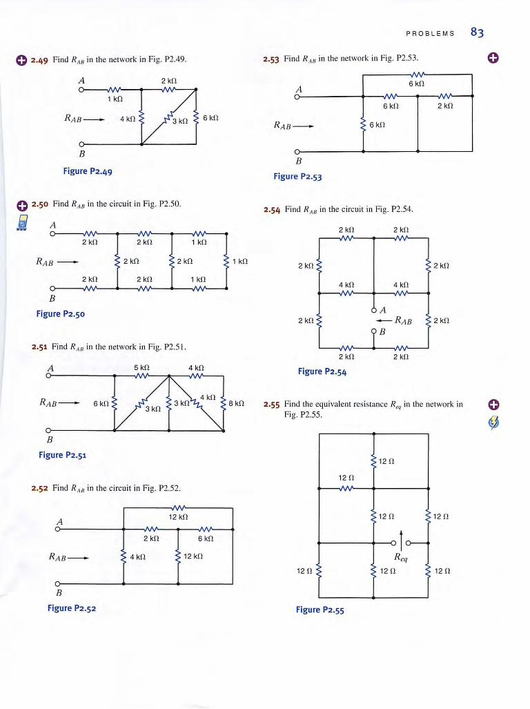
o 2·49 Find R AIl in the network in Fig. P2.49.
A
1 kfl
RAB_
B
Figure P2.49
o 2.50 Find R AB in the circuit in Fig. P2.50.
i A o---~~--~~~--~-,~--~
2 ~n 2 kfl 1 kfl
R AB - 2 kfl 2 kfl
2 kfl 2 kfl 1 kfl
B
Figure P2.50
2.51 Find R,w in the ne(work in Fig. P2.S I.
A
B
Figure P2.51
2.52 Find R AIl in the circuit in Fig. P2.S2.
A 12 kfl
2 kfl 6kfl
R AB - 4 kfl 12 kfl
B
Figure P2.52
8 kfl
P ROBLEMS 83
2.53 Fi nd R"H in the network in Fig. P2.5 3.
A 6 kfl
6 kfl
- 6 kfl
B
Figure P2 .53
2.54 Find R A/J in the circuit in Fig. P2.54.
2 kfl
4 kfl
2 kfl
Figure P2.54
4 kfl
A - R AB ,B
2 kfl
2 kfl
2 .55 Find the equiva lent resistance R l'q in the network in Fig. P2.SS .
12 fl
12fl
12 fl 12 fl
Jcr--R eq
12 fl 12 fl
Figure P2.55
o
84 CHAPTER 2 RESISTI V E CIRCUITS
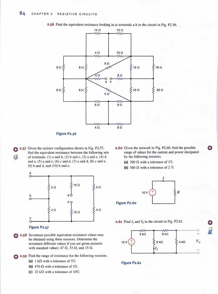
2.56 Find the equiva lent resistance looking in at terminals a-b in the circuit in Fig. P2.56.
12 0 10 0
40
80 80 80
40
80 80
60
40
Figure P2.56
o 2·57 Given the resistor configuration shown in Fig. P2.57, find the equivalent resistance between the following sets
<!) of tenninals: ( I) a and b, (2) band c, (3) a and c. (4) d ~d~~)a~d~~c~~ma~d,~)ca~~ (9) band d, and ( 10) band e.
0 2 .58
a
50 100
50
b d
e
40 120
40
c
Figure P2.57
Seventeen possible equivalent resistance values may be obtained using three resistors. Detennine the seventeen different values if you are given resistors with standard values: 47 n, 33 n, and 15 n.
o 2·59 Find the range of resistance for the following resistors.
(al I kn with a lolerance of 5%
(bl 470 n with a tolerance of 2%
(el 22 kn wilh a tolerance of 10%
100
120 180
80
100 200
90
60
2.60 Given the network in Fig. P2.60, find the poss ible range of values for the current and power dissipated by the following resistors.
(al 390 n with a tolerance of 1%
(bl 560 n with a tolerance of 2 %
10 V
Figure P2.60
R
2.61 Find II and Vo in the circuit in Fig. P2.61 .
2 kO 8 kO
12V 4 kO
Figure P2,61
+
o

) 2.62 Find /, and Vo in the circuit in Fig. P2.62.
6V t2 kO 4 kO
Figure P2.62
, 2.63 Find Vub and ~Ir in the circuit in Fig. P2.63.
+ Vab b a
20 <b 50
20 V :!:
40 + d 30
10
c 20
Figure P2.63
2.64 Find VI and fA in the network in Fig P2.64.
16 kO
+
15 V 10 kO
Figure P2.64
2.65 Find lo in the network in Fig. P2.65.
6 kO
12 kO 12 kO
Figure P2.65
2.66 Determine l o in the circuit in Fig. P2.66.
6kO
12kO 4kO 2 kO
4 kO 16 kO
CY 12V
Figure P2.66
+
12 kO
PROBLEMS 85
2.67 Find V, in the network in Fig P2.67.
50
24 V
30
Figure P2.67
so
100
60
30
2.68 Determine Vo in the network in Fig. P2.68.
5kO
1S rnA 3kO
1 kO
Figure P2.68
2.69 Find V~b in the circuit in Fig P2.69.
90 150 100
20
Figure P2.69
2.70 Find V,/b in the network in Fig P2.70.
50 30 20
30
Figure P2.70
60
60
86 C H APTER 2 RES I S TI VE C I RCUITS
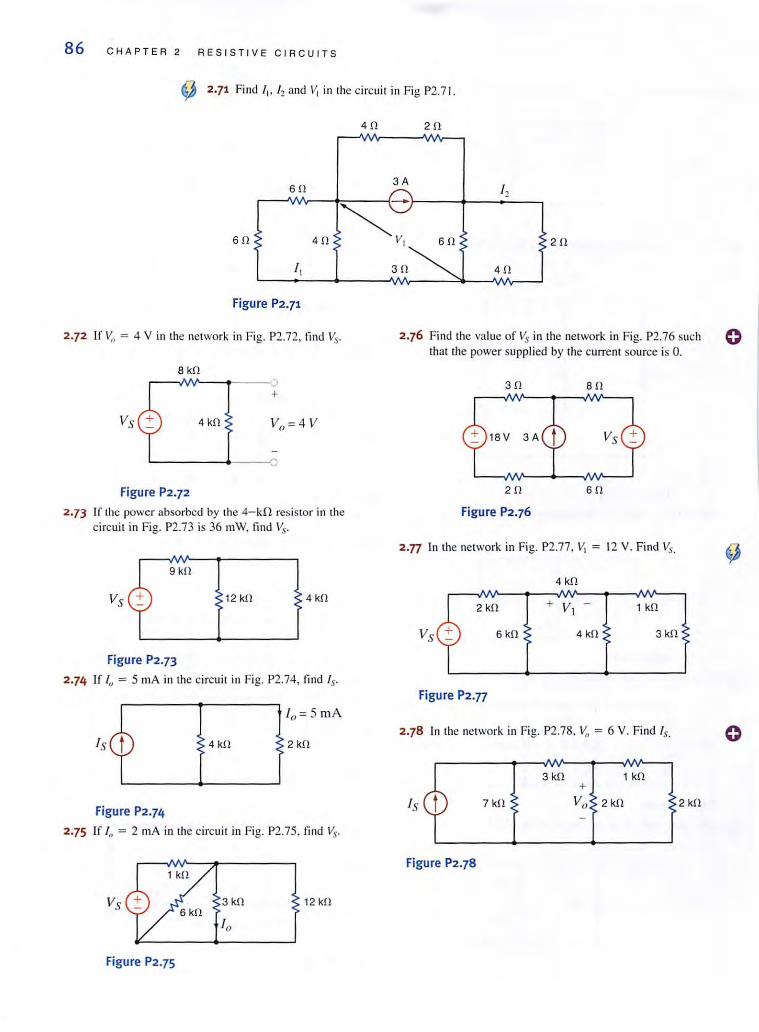
~ 2·71 Find 'I> '2 and Vi in the circuit in Fig P2.7!.
40 20
60 3A
I ,
60
~-
v~~ 40
I,
Figure P2.71
2.72 If Vo = 4 V in the network in Fig. P2.72, find Vs.
8 kO
+
Vs 4 kO
~---4---O
Figure P2.72
2.73 Ir the power absorbed by the 4- kfl res istor in the circuit in Fig. P2.?3 is 36 mW, find Vs.
9 kO
12 kO 4kO
Figure P2.73
2.74 If 10 = 5 rn A in the circuit in Fig. P2.74, find Is-
10 = 5 rnA
4 kO 2 kO
Figure P2.74
2.75 If I" = 2 rn A in the circui t in Fig. P2.75, find ~"
12 kO 6 kO
Figure P2.75
20
30 40
2.76 Find the va lue of Vs in the network in Fig. P2.76 such that the power supplied by the current source is O.
30
20
Figure P2.76
80
60
2.n In the network in Fig. P2.??, VI = 12 V. Find Vs.
4 kO
2 kO 1 kO
6kO 4 kO 3kO
Figure P2.77
2.78 In the network in Fig. P2.78, ~J = 6 V. Find Is.
3 kO 1 kO +
IS 7 kO Vo 2kO
Figure P2.78
2 kO
(}

2.79 In the circui t in Fig. P2.79, v,! = 2 V. Find Is.
12 II 2ll Sll +
10 II IS 3ll 4ll
~------+-------~------~-----o
Figure P2.79
o 2.80 Find the va lue of VI in the network in Fig. P2.80 sti ch that v" = O.
SV 2ll
-+ +
2ll
Va 2ll 4 II 2ll
VI + -
Figure P2.80
o 2.81 If VI = 5 V in the c ircuit in Fig. P2.8 1, fi nd Is.
4 kll IS 6 kll 3 kll
Figure P2.81
C 2.82 In the network in Fig. P2.82, VI = 12 V. Find Vs.
4kll
2 kll 1 kll
6 kll 4 kll 3 kil
Figure P2.82
0 2 .83 Given that V(! = 4 V in the network in Fig. P2.83. fi nd Vs.
~
3 kll
Figure P2.83
6V
12 kll
3 kfl 2 kll
2mA 1 kll
PROBLEMS 87
2 .84 Given that IA' = 4 A, li nd R. V" b, and the power supp lied by the IO-A current source in the network in Fig. P2.S4.
4ll a 40V
Sll +
\ 20 ll
V (lU
10 A t ----- b R
1.\. 10 II
Figure P2.84
2.85 Find the val ue of V..- in the network in Fig. P2.8S, Stich that the 5-A curre nt source supplies 50 W.
2ll
4ll
4ll
5V 2fl 2ll SA
Figure P2.8S
2.86 If the power ;lbsorbcd by the 6-A CUITent source in the circui t in Fig. P2.86 is 144 W, fi nd Vs and the power supp lied by the 24-V voltage source.
6A 4ll
4fl
12ll
Vs Sll 4ll 24 V
Figure P2.86
88 CHAPTER 2 RESISTIVE C I RCUITS
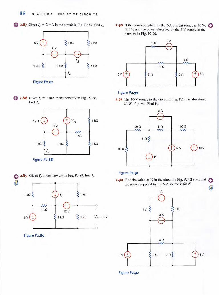
o 2.87 Given I" = 2 mA in the circuit in Fig. P2.87, tind (t.
SV + 1 kO 2 kO
SV
1 kO 2 kO 1 kO
Figure P2.87
e 2.88 Given /0 = 2 mA in the network in Fig. Pl.SS, find VII-
SmA 1 kO
SV
- +\___---+---NV'----1 1 kO
1 kO 2 kO 2 kO
Figure P2.88
e 2.89 Given Vo in the network in Fig. P2.89, find IA·
~
1 kO 1 kO
~ __ AN~~-~+-\____+---~
1 kO
SV + 12 V
2 kO
+
1 kO
L-____ ~------~-----o
Figure P2.89
2·90 If the power supplied by the 2·A current source is 40 w. e find Vs and the power absorbed by the 5· V source in the network in Fig. P2.90.
50 2A
50
100
5V 50 50
Figure P2.90
2.91 The 40-V source in the circuit in Fig. P2.9 1 is absorbing 80 W of power. Find V,.
3A
200 50 100
SO
100 t 5A + 40V
+ V,.
Figure P2.91
2.92 Find the value of Vx in the circuit in Fig. P2.92 such that the power supplied by the 5-A source is 60 W.
10 10
3A
40
5V 20 20 5 A
Figure P2.92

2.93 Given that \II = 4 V, find VA and RIJ in the circuit in Fig. P2.93.
VA 16 V + - +-
4mA
4 kn RB 6 kn
8V SmA
2 kn
Figure P2.93
o 2·94 Find the power absorbed by the network in Fig. P2.94.
12 kn
2 kn 18 kn
Figure P2.94
Find the value of g in the network in Fig. P2.95 sllch Ihal the power supplied by the 3-A sOllrce is 20 W.
I gl,
PROBLEMS 89
2.97 Find I" in the circuit in Fig. P2.97 .
12 n
+ 24 V -12 n
8n 14 n
10
Figure P2.97
2.98 Fi nd 10 in the circui t ill Fig. P2.98.
3n
36V 12 n 4 n
sn
18 n
Figure P2.98
2.99 Determine the value of Vo in the network in Fig. P2.99. 0 12 kn
0 +
6kn 18 kn
4kn 6 kn V
""+ -
a
Figure P2.95 Figure P2·99
o 2.96 Find the power supplied by the 24-V source in the circui t in Fig. P2.96.
12kn 12 kn
12 kil ~ 12 kn
24 V
12 kn 12 kn
Figure P2.96
2 .100 Find the power supplied by the 6- V source in the network in Fig. P2.1 00.
12 kn 12 kn
12 kn + 12 kn
6V
12 kn 12 kn
Figure P2.100
90 CHAPTER 2 R E SIST IV E CIRC UI TS
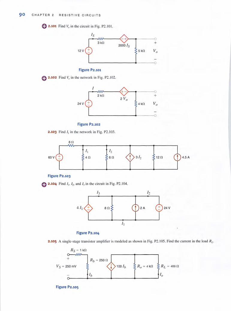
o 2.101 Find Vo in the circui t in Fig. P2. 1 01.
IS ~~NV~-----(-+·>-~~--------O
3 kO
12 V
Figure P2.101
e 2.102 Fi nd V:, in the network in Fig. P2.102.
I
+ 2000 IS
5 kO
.. ~~----~+->-~------~ 2 kO
24 V
Figure P2.102
2.103 Find I I in the network in Fig. P2.I03.
s o
60V
Figure P2.103
I ,
40
I ,
60
0 2.104 Find I •. 12, and h in the circuit in Fig. P2. 104.
so
Figure P2.104
+
4kO
120
12
4.SA
24 V
2.105 A single-stage transistor ampli licr is modeled as shown in Fig. P2. 1 05. Find the current in the load RL.
Rs = 1 kO
+
VS = 2S0mV Ro = 4 kfl
Figure P2.105

PROBLEMS 91
o 2.106 Find l o in the network in Fig. P2. 1 06.
fj -eo
60 --0 t 5A ! 3 V, +
40 V, 10
-
Figure P2.106
C 2.107 A I),picailransislor amplifier is shown in Fig. P2.I07. Find the ampli fier gain G (i.e., the ratio of the output voltage 10 the input voltage).
1000 4 kO r--III0---1~------"O
+
Vs ~ 250mV 5 kO 5000
Figure P2.107
~ 2.108 Find the power absorbed by the 12-kfl res istor in the network in rig. P2.I08.
+
4 kO
6mA t 4 kO 3 10 ! Vo 12 kO
6 kO 3 kO
10 -
Figure P2.108
e 2.109 Find the power absorbed by the 12-kn resistor in the network in Fig. P2. I09.
+
4 kO 12 kO
5mA t 2 kO V, ! Vo 2000 +
12 kO
V, 3kO
--
Figure P2.109