p. foraboschi/engineering failure analysis 33 (2013) … · the building dangerous. in addition,...
TRANSCRIPT

This article appeared in a journal published by Elsevier. The attached copy is furnished to the author for internal non-commercial research
and educational use, including for instruction at the author’s institution and sharing with colleagues.
Other uses, including reproduction and distribution, or selling or
licensing copies, or posting to personal, institutional or third party websites are prohibited.
In most cases authors are permitted to post their version of the
article (e.g. in Word or Tex form) to their personal website or institutional repository. Authors requiring further information
regarding Elsevier’s archiving and manuscript policies are encouraged to visit:
http://www.elsevier.com/copyright
Engineering Failure Analysis 33 (2013) 281–314
Author's Personal Copy
Contents lists available at SciVerse ScienceDirect
Engineering Failure Analysis
journal homepage: www.elsevier .com/locate /engfai lanal
Church of San Giuliano di Puglia: Seismic repair and upgrading
1350-6307/$ - see front matter � 2013 Elsevier Ltd. All rights reserved.http://dx.doi.org/10.1016/j.engfailanal.2013.05.023
⇑ Tel.: +39 041 2571289; fax: +39 51392909.E-mail address: [email protected]
Paolo Foraboschi ⇑Dipartimento Architettura Costruzione Conservazione, Università IUAV di Venezia, Italy
a r t i c l e i n f o
Article history:Received 20 February 2013Received in revised form 12 May 2013Accepted 28 May 2013Available online 6 June 2013
Keywords:Enhance energy dissipationInternal confinementMasonry churchMasonry framePrestressed masonry
a b s t r a c t
The notorious October-31-2002 earthquake threatened the collapse of the church of SanGiuliano di Puglia (Campobasso, Italy). This paper describes the main points of the repairand seismic retrofitting of the town church, San Giuliano Martire. The seismic retrofittinghad to meet the new Italian seismic code that was issued immediately after this earth-quake (seismic upgrading). The structural rehabilitation was limited because of therequirements to stay true to the original aspect (conservation of the bare-surface stonemasonry, without plaster). To this end, the design considered recent scientific advance-ments and developed innovative methods, rather than just referring to technical practice.
The rehabilitation work, in particular the technical innovation, has been tested by twoearthquakes, both of them with an epicenter within close proximity to the building. Thefirst one struck in 2007, with a magnitude of 3.1; the second one in 2011, with a magnitudeof 3.7 and a Peak Ground Acceleration of 0.19�g. Whilst the sacral furniture resting on theground suffered from significant damage, none of the earthquakes caused any structuraldamage to the building. In particular, no cracks opened in the masonry structures. ThePGA and seismic forces of the 2011-earthquake were 1.7 and 2.5 times greater than the val-ues prescribed by the present Italian code for the damage limitation and no-collapserequirements, respectively. This proves the effectiveness of applying post-tensionedbonded tendons to masonry structures, in order to significantly increase both the stiffnessand the lateral load-carrying capacity of a masonry building.
� 2013 Elsevier Ltd. All rights reserved.
1. Introduction
This paper presents an example of the repair of seismic damage and seismic upgrading of a historical building. The casethat the paper deals with is the church of San Giuliano Martire (Figs. 1–8), which is located in San Giuliano di Puglia, a townnear Campobasso, in Italy (Region of Molise).
The notorious October-31-2002 earthquake caused serious damage throughout the area of San Giuliano di Puglia. Aboveall, the earthquake caused the collapse of the Francesco Jovine elementary school, which resulted in the death of 27 pupilsand one teacher, and left many other pupils and teachers wounded. Moreover, the earthquake caused damage to many build-ings, especially to the masonry constructions, which were the vast majority of the buildings in the town.
The Peak Ground Acceleration (PGA) of the earthquake was not particularly high in comparison to the real seismic hazardof that area. In particular, the magnitude was of 5.78 on the Richter scale and the epicenter was not close to San Giuliano diPuglia. Unfortunately, the quality of the masonry constructions of the area was poor, and consequentially many buildingscould not endure the earthquake, in particular those with large rooms.
The town church was in the most critical condition, since it was about to collapse. Thus, during the emergency actionsimmediately after the earthquake, the church was shut and the surrounding area was closed, since the damage had rendered
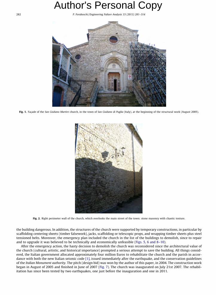
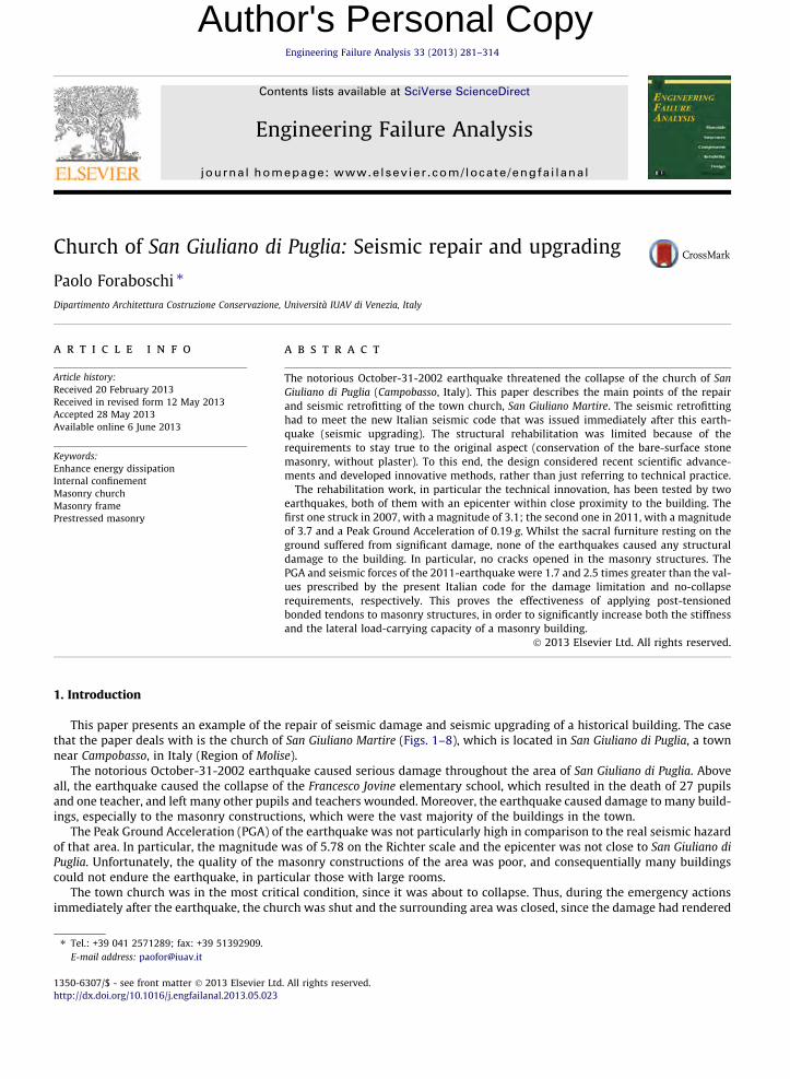
Fig. 1. Façade of the San Giuliano Martire church, in the town of San Giuliano di Puglia (Italy), at the beginning of the structural work (August 2005).
Fig. 2. Right perimeter wall of the church, which overlooks the main street of the town: stone masonry with chaotic texture.
282 P. Foraboschi / Engineering Failure Analysis 33 (2013) 281–314
Author's Personal Copy
the building dangerous. In addition, the structures of the church were supported by temporary constructions, in particular byscaffolding centering sheets (timber falsework), jacks, scaffolding or telescopic props, and wrapping timber sheets plus steeltensioned belts. Moreover, the emergency plan included the church in the list of the buildings to demolish, since to repairand to upgrade it was believed to be technically and economically unfeasible (Figs. 5, 6 and 8–10).
After the emergency action, the hasty decision to demolish the church was reconsidered since the architectural value ofthe church (cultural, artistic, and historical importance) prompted a serious attempt to save the building. All things consid-ered, the Italian government allocated approximately four million Euros to rehabilitate the church and the parish in accor-dance with both the new Italian seismic code [1], issued immediately after the earthquake, and the conservation guidelinesof the Italian Monument authority. The pitch (design bid) was won by the author of this paper, in 2004. The construction workbegan in August of 2005 and finished in June of 2007 (Fig. 7). The church was inaugurated on July 21st 2007. The rehabil-itation has since been tested by two earthquakes, one just before the inauguration and one in 2011.
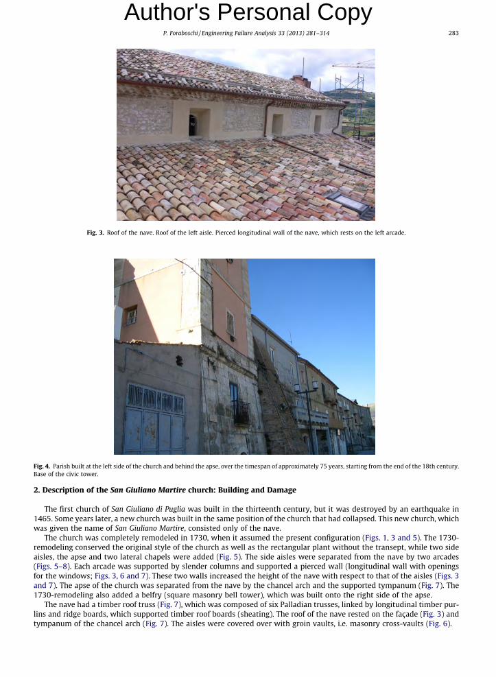
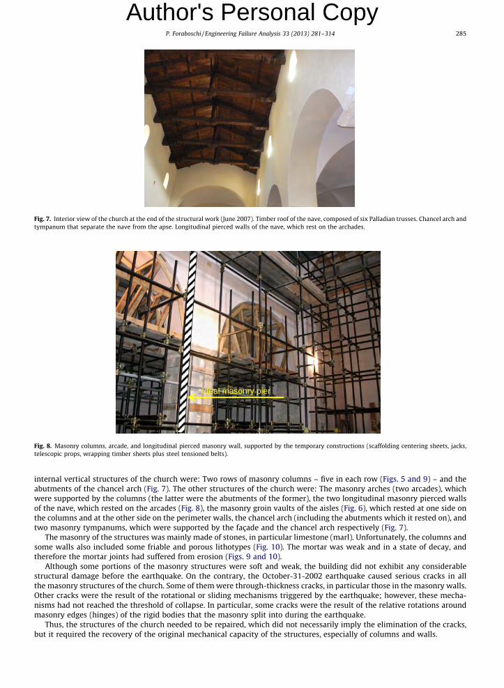
Fig. 4. Parish built at the left side of the church and behind the apse, over the timespan of approximately 75 years, starting from the end of the 18th century.Base of the civic tower.
Fig. 3. Roof of the nave. Roof of the left aisle. Pierced longitudinal wall of the nave, which rests on the left arcade.
P. Foraboschi / Engineering Failure Analysis 33 (2013) 281–314 283
Author's Personal Copy
2. Description of the San Giuliano Martire church: Building and Damage
The first church of San Giuliano di Puglia was built in the thirteenth century, but it was destroyed by an earthquake in1465. Some years later, a new church was built in the same position of the church that had collapsed. This new church, whichwas given the name of San Giuliano Martire, consisted only of the nave.
The church was completely remodeled in 1730, when it assumed the present configuration (Figs. 1, 3 and 5). The 1730-remodeling conserved the original style of the church as well as the rectangular plant without the transept, while two sideaisles, the apse and two lateral chapels were added (Fig. 5). The side aisles were separated from the nave by two arcades(Figs. 5–8). Each arcade was supported by slender columns and supported a pierced wall (longitudinal wall with openingsfor the windows; Figs. 3, 6 and 7). These two walls increased the height of the nave with respect to that of the aisles (Figs. 3and 7). The apse of the church was separated from the nave by the chancel arch and the supported tympanum (Fig. 7). The1730-remodeling also added a belfry (square masonry bell tower), which was built onto the right side of the apse.
The nave had a timber roof truss (Fig. 7), which was composed of six Palladian trusses, linked by longitudinal timber pur-lins and ridge boards, which supported timber roof boards (sheating). The roof of the nave rested on the façade (Fig. 3) andtympanum of the chancel arch (Fig. 7). The aisles were covered over with groin vaults, i.e. masonry cross-vaults (Fig. 6).

Fig. 6. Right aisle immediately after the October-31-2002 earthquake.
Fig. 5. Interior view of the church. The photo was taken during the emergency action devoted to placing the temporary constructions, in order to support allthe structures (November 2002).
284 P. Foraboschi / Engineering Failure Analysis 33 (2013) 281–314
Author's Personal Copy
Many years after the 1730-remodeling, a parish (house) was added onto the left side of the church and behind the apse(Fig. 4). The parish was structurally connected to the church, since the two buildings shared the longitudinal wall. The parishincluded another belfry (civic tower; Fig. 4). Due to the slope of the soil, the parish was on three levels and the bottom of theparish was approximately nine meters below the foundation of the church (Fig. 4). Thus, the perimeter wall that separatedthe church from the parish was a retaining wall (i.e., the left wall of the church was a thrust wall).
The façade overlooked the town square (Fig. 1) and the right side of the church overlooked the main street of the town(Fig. 2). Thus, these two sides of the building were free (outside walls). Conversely, the left side of the church and the apsewere attached to the parish (Fig. 4), which connected the vibration of the church to that of the parish.
The external vertical structures of the church were: The masonry wall that made up the façade (Fig. 1), the right perimeterwall (Fig. 2), the masonry wall that made up the apse and the perimeter wall that separated the church from the parish. The
Ideal masonry pier
Fig. 8. Masonry columns, arcade, and longitudinal pierced masonry wall, supported by the temporary constructions (scaffolding centering sheets, jacks,telescopic props, wrapping timber sheets plus steel tensioned belts).
Fig. 7. Interior view of the church at the end of the structural work (June 2007). Timber roof of the nave, composed of six Palladian trusses. Chancel arch andtympanum that separate the nave from the apse. Longitudinal pierced walls of the nave, which rest on the archades.
P. Foraboschi / Engineering Failure Analysis 33 (2013) 281–314 285
Author's Personal Copy
internal vertical structures of the church were: Two rows of masonry columns – five in each row (Figs. 5 and 9) – and theabutments of the chancel arch (Fig. 7). The other structures of the church were: The masonry arches (two arcades), whichwere supported by the columns (the latter were the abutments of the former), the two longitudinal masonry pierced wallsof the nave, which rested on the arcades (Fig. 8), the masonry groin vaults of the aisles (Fig. 6), which rested at one side onthe columns and at the other side on the perimeter walls, the chancel arch (including the abutments which it rested on), andtwo masonry tympanums, which were supported by the façade and the chancel arch respectively (Fig. 7).
The masonry of the structures was mainly made of stones, in particular limestone (marl). Unfortunately, the columns andsome walls also included some friable and porous lithotypes (Fig. 10). The mortar was weak and in a state of decay, andtherefore the mortar joints had suffered from erosion (Figs. 9 and 10).
Although some portions of the masonry structures were soft and weak, the building did not exhibit any considerablestructural damage before the earthquake. On the contrary, the October-31-2002 earthquake caused serious cracks in allthe masonry structures of the church. Some of them were through-thickness cracks, in particular those in the masonry walls.Other cracks were the result of the rotational or sliding mechanisms triggered by the earthquake; however, these mecha-nisms had not reached the threshold of collapse. In particular, some cracks were the result of the relative rotations aroundmasonry edges (hinges) of the rigid bodies that the masonry split into during the earthquake.
Thus, the structures of the church needed to be repaired, which did not necessarily imply the elimination of the cracks,but it required the recovery of the original mechanical capacity of the structures, especially of columns and walls.
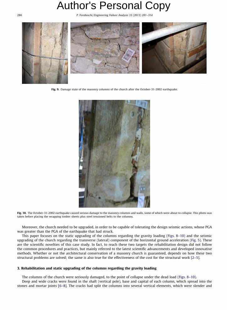
Fig. 9. Damage state of the masonry columns of the church after the October-31-2002 earthquake.
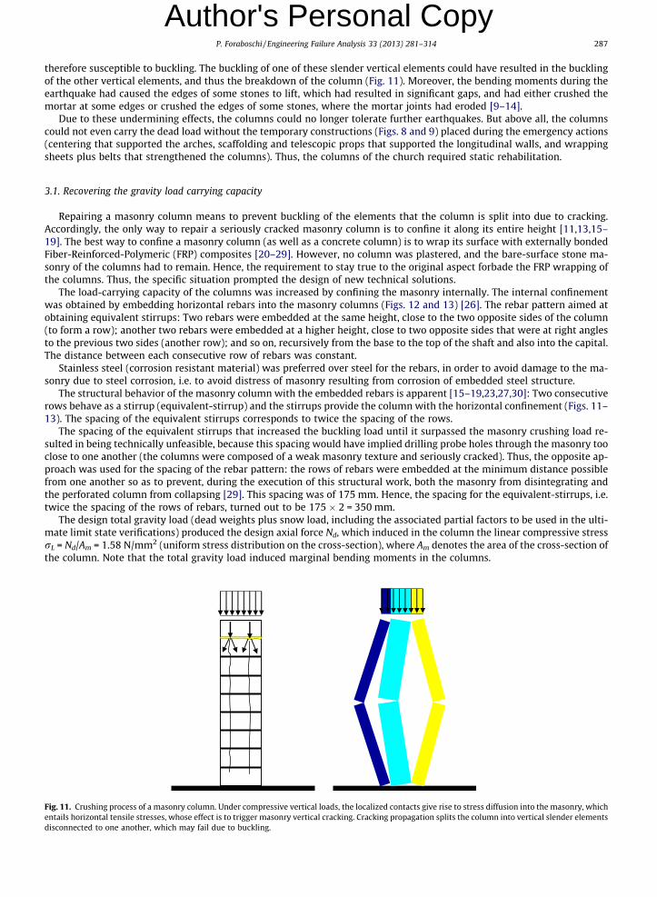
Fig. 10. The October-31-2002 earthquake caused serious damage to the masonry columns and walls, some of which were about to collapse. This photo wastaken before placing the wrapping timber sheets plus steel tensioned belts to the columns.
286 P. Foraboschi / Engineering Failure Analysis 33 (2013) 281–314
Author's Personal Copy
Moreover, the church needed to be upgraded, in order to be capable of tolerating the design seismic actions, whose PGAwas greater than the PGA of the earthquake that had struck.
This paper focuses on the static upgrading of the columns regarding the gravity loading (Figs. 8–10) and the seismicupgrading of the church regarding the transverse (lateral) component of the horizontal ground acceleration (Fig. 5). Theseare the scientific novelties of this case study. In fact, to reach these two targets the rehabilitation design did not followthe common procedures and practices, but mainly referred to the latest scientific advancements and developed innovativemethods. Whether or not the architectural conservation of a masonry church is guaranteed, depends on how these twostructural problems are solved; the same is also true for the effectiveness of the cost for the structural work [2–5].
3. Rehabilitation and static upgrading of the columns regarding the gravity loading
The columns of the church were seriously damaged, to the point of collapse under the dead load (Figs. 8–10).Deep and wide cracks were found in the shaft (vertical pole), base and capital of each column, which spread into the
stones and mortar joints [6–8]. The cracks had split the columns into several vertical elements, which were slender and
P. Foraboschi / Engineering Failure Analysis 33 (2013) 281–314 287
Author's Personal Copy
therefore susceptible to buckling. The buckling of one of these slender vertical elements could have resulted in the bucklingof the other vertical elements, and thus the breakdown of the column (Fig. 11). Moreover, the bending moments during theearthquake had caused the edges of some stones to lift, which had resulted in significant gaps, and had either crushed themortar at some edges or crushed the edges of some stones, where the mortar joints had eroded [9–14].Due to these undermining effects, the columns could no longer tolerate further earthquakes. But above all, the columnscould not even carry the dead load without the temporary constructions (Figs. 8 and 9) placed during the emergency actions(centering that supported the arches, scaffolding and telescopic props that supported the longitudinal walls, and wrappingsheets plus belts that strengthened the columns). Thus, the columns of the church required static rehabilitation.
3.1. Recovering the gravity load carrying capacity
Repairing a masonry column means to prevent buckling of the elements that the column is split into due to cracking.Accordingly, the only way to repair a seriously cracked masonry column is to confine it along its entire height [11,13,15–19]. The best way to confine a masonry column (as well as a concrete column) is to wrap its surface with externally bondedFiber-Reinforced-Polymeric (FRP) composites [20–29]. However, no column was plastered, and the bare-surface stone ma-sonry of the columns had to remain. Hence, the requirement to stay true to the original aspect forbade the FRP wrapping ofthe columns. Thus, the specific situation prompted the design of new technical solutions.
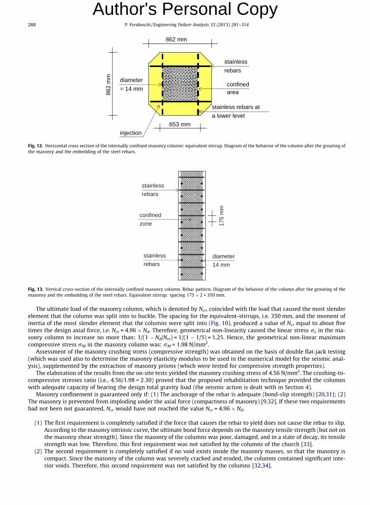
The load-carrying capacity of the columns was increased by confining the masonry internally. The internal confinementwas obtained by embedding horizontal rebars into the masonry columns (Figs. 12 and 13) [26]. The rebar pattern aimed atobtaining equivalent stirrups: Two rebars were embedded at the same height, close to the two opposite sides of the column(to form a row); another two rebars were embedded at a higher height, close to two opposite sides that were at right anglesto the previous two sides (another row); and so on, recursively from the base to the top of the shaft and also into the capital.The distance between each consecutive row of rebars was constant.
Stainless steel (corrosion resistant material) was preferred over steel for the rebars, in order to avoid damage to the ma-sonry due to steel corrosion, i.e. to avoid distress of masonry resulting from corrosion of embedded steel structure.
The structural behavior of the masonry column with the embedded rebars is apparent [15–19,23,27,30]: Two consecutiverows behave as a stirrup (equivalent-stirrup) and the stirrups provide the column with the horizontal confinement (Figs. 11–13). The spacing of the equivalent stirrups corresponds to twice the spacing of the rows.
The spacing of the equivalent stirrups that increased the buckling load until it surpassed the masonry crushing load re-sulted in being technically unfeasible, because this spacing would have implied drilling probe holes through the masonry tooclose to one another (the columns were composed of a weak masonry texture and seriously cracked). Thus, the opposite ap-proach was used for the spacing of the rebar pattern: the rows of rebars were embedded at the minimum distance possiblefrom one another so as to prevent, during the execution of this structural work, both the masonry from disintegrating andthe perforated column from collapsing [29]. This spacing was of 175 mm. Hence, the spacing for the equivalent-stirrups, i.e.twice the spacing of the rows of rebars, turned out to be 175 � 2 = 350 mm.
The design total gravity load (dead weights plus snow load, including the associated partial factors to be used in the ulti-mate limit state verifications) produced the design axial force Nd, which induced in the column the linear compressive stressrL = Nd/Am = 1.58 N/mm2 (uniform stress distribution on the cross-section), where Am denotes the area of the cross-section ofthe column. Note that the total gravity load induced marginal bending moments in the columns.
Fig. 11. Crushing process of a masonry column. Under compressive vertical loads, the localized contacts give rise to stress diffusion into the masonry, whichentails horizontal tensile stresses, whose effect is to trigger masonry vertical cracking. Cracking propagation splits the column into vertical slender elementsdisconnected to one another, which may fail due to buckling.
confined area
stainless rebars
injection
862 mm
653 mm
diameter = 14 mm
862
mm
stainless rebars at a lower level
Fig. 12. Horizontal cross section of the internally confined masonry column: equivalent stirrup. Diagram of the behavior of the column after the grouting ofthe masonry and the embedding of the steel rebars.
stainless rebars
stainless rebars
confined zone 17
5 m
m
diameter 14 mm
Fig. 13. Vertical cross-section of the internally confined masonry column. Rebar pattern. Diagram of the behavior of the column after the grouting of themasonry and the embedding of the steel rebars. Equivalent stirrup: spacing 175 � 2 = 350 mm.
288 P. Foraboschi / Engineering Failure Analysis 33 (2013) 281–314
Author's Personal Copy
The ultimate load of the masonry column, which is denoted by Ncr, coincided with the load that caused the most slenderelement that the column was split into to buckle. The spacing for the equivalent-stirrups, i.e. 350 mm, and the moment ofinertia of the most slender element that the columns were split into (Fig. 10), produced a value of Ncr equal to about fivetimes the design axial force, i.e. Ncr = 4.96 � Nd. Therefore, geometrical non-linearity caused the linear stress rL in the ma-sonry column to increase no more than: 1/(1 � Nd/Ncr) = 1/(1 � 1/5) = 1.25. Hence, the geometrical non-linear maximumcompressive stress rM in the masonry column was: rM = 1.98 N/mm2.
Assessment of the masonry crushing stress (compressive strength) was obtained on the basis of double flat-jack testing(which was used also to determine the masonry elasticity modulus to be used in the numerical model for the seismic anal-ysis), supplemented by the extraction of masonry prisms (which were tested for compressive strength properties).
The elaboration of the results from the on-site tests yielded the masonry crushing stress of 4.56 N/mm2. The crushing-to-compressive stresses ratio (i.e., 4.56/1.98 = 2.30) proved that the proposed rehabilitation technique provided the columnswith adequate capacity of bearing the design total gravity load (the seismic action is dealt with in Section 4).
Masonry confinement is guaranteed only if: (1) The anchorage of the rebar is adequate (bond-slip strength) [20,31]; (2)The masonry is prevented from imploding under the axial force (compactness of masonry) [9,32]. If these two requirementshad not been not guaranteed, Ncr would have not reached the value Ncr = 4.96 � Nd.
(1) The first requirement is completely satisfied if the force that causes the rebar to yield does not cause the rebar to slip.According to the masonry intrinsic curve, the ultimate bond force depends on the masonry tensile strength (but not onthe masonry shear strength). Since the masonry of the columns was poor, damaged, and in a state of decay, its tensilestrength was low. Therefore, this first requirement was not satisfied by the columns of the church [33].
(2) The second requirement is completely satisfied if no void exists inside the masonry masses, so that the masonry iscompact. Since the masonry of the column was severely cracked and eroded, the columns contained significant inte-rior voids. Therefore, this second requirement was not satisfied by the columns [32,34].

P. Foraboschi / Engineering Failure Analysis 33 (2013) 281–314 289
Author's Personal Copy
Ultimately, these two shortcomings would have nullified the confining action of the rebars, causing Ncr to be lower thanthe predicted value. Therefore, before embedding the rebars into the masonry, the columns were grouted, i.e. grout was in-jected under pressure through ports into the masonry.
Grouting does not considerably increase the load-carrying capacity of a masonry structure, since a masonry structure car-ries the load by virtue of the masses and not by virtue of the material strength [27,29,32,35–37]. Thus, to increase the ma-sonry compressive strength is pointless for the load-carrying capacity. Accordingly, the grouting work aimed only atincreasing the tensile strength of the masonry and eliminating the voids, which provided the masonry with higher bondstrength and compactness. The bond strength of the grouted masonry guaranteed the anchorage of rebars with up to16 mm of diameter. The diameter adopted for the embedded rebars was 14 mm, which, hence, guaranteed that the debond-ing force surpassed the yielding force of the rebar. More specifically, the former was 109.69 kN and the latter was 76.12 kN.Ultimately, in the grouted columns, the anchorage length of the rebar was sufficient for bearing the yielding force of the re-bar; moreover, the compression of masonry could not result in the implosion of the column any longer.
According to the above, the grouting work aimed at permeating the masonry voids and mixing with the masonry debris.Therefore, the mortar mix that was injected had been specifically designed so as to guarantee chemical compatibility, goodcapacity of penetrating into the masses, and good capacity of stitching the crack mouths to each other. Conversely, the gro-uting work did not aim at increasing the compressive strength of masonry, whereas it aimed at improving the cyclic loadcapacity [38]. Note that, since the grout had stitched the crack mouths, the actual value of Ncr was greater than the predictedvalue. The ingredients for the injected grout were natural hydraulic lime, sand, water, and admixtures, all non-chloride andnon-corrosive. No cement was used, since it would have given rise to delayed ettringite formation, which would have beenharmful. A series of injection ports with staggered pattern was drilled into the masonry; then the grout mix was injectedunder pressure (pressure < 0.4 N/mm2) through the ports into the masonry, having sealed the cracks between the ports withremovable non-staining clay mortar.
3.2. Restoration process of the surface of the masonry columns
After the masonry grouting and the embedding of the rebars, the columns underwent a process of restoration. More spe-cifically, a restoration team restored the surface of each column to its original condition. The restoration team executed twojobs, namely i. hiding the rebars ii. and repointing [11].
i. Troncoconical pieces of limestone were epoxy-bonded onto the head of each rebar. To this end, each head produced arecess into the column (an eight millimeter groove; Fig. 14), so that the external surface of the troncoconical limestoneformed no discontinuity with respect to the surface of the column (Fig. 15). In doing so, the heads of the rebars werecovered by the bare-surface stone masonry.
ii. Repointing refilled the joints with new material, which allowed the external part of the mortar joints to be renewed.Before refilling the joints, the damaged mortar was removed (with a grinder, to avoid damage to the column). Themortar used for repointing had a similar performance and similar aesthetic characteristics to the original mortar usedin the column; in particular, it was physically and architectonically compatible with the masonry of the columns (limemortar). In so doing, not only were the vanished parts of the columns reconstructed, but the exact form and details ofthe masonry surfaces were reproduced (Fig. 16).
Finally, the five plus five masonry columns of the church were restored back to their original look (Fig. 16).
Fig. 14. Column after the grouting of masonry and the embedding of the steel rebars, but before the restoration. The head of each rebar produced a recessinto the column to allow the rebar to be hidden.
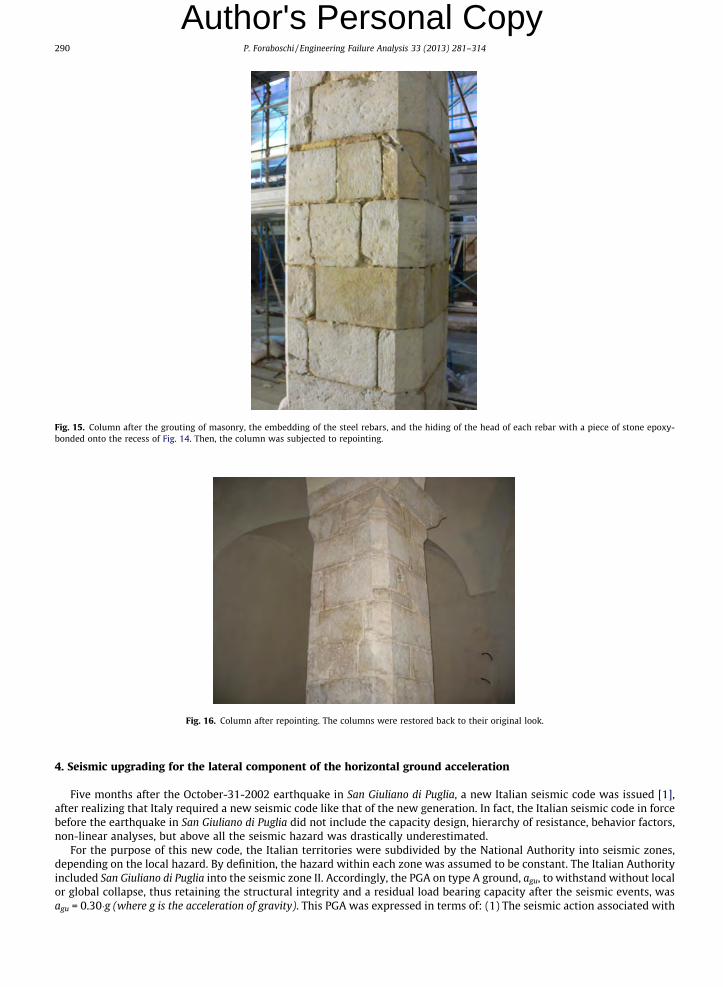
Fig. 15. Column after the grouting of masonry, the embedding of the steel rebars, and the hiding of the head of each rebar with a piece of stone epoxy-bonded onto the recess of Fig. 14. Then, the column was subjected to repointing.
Fig. 16. Column after repointing. The columns were restored back to their original look.
290 P. Foraboschi / Engineering Failure Analysis 33 (2013) 281–314
Author's Personal Copy
4. Seismic upgrading for the lateral component of the horizontal ground acceleration
Five months after the October-31-2002 earthquake in San Giuliano di Puglia, a new Italian seismic code was issued [1],after realizing that Italy required a new seismic code like that of the new generation. In fact, the Italian seismic code in forcebefore the earthquake in San Giuliano di Puglia did not include the capacity design, hierarchy of resistance, behavior factors,non-linear analyses, but above all the seismic hazard was drastically underestimated.
For the purpose of this new code, the Italian territories were subdivided by the National Authority into seismic zones,depending on the local hazard. By definition, the hazard within each zone was assumed to be constant. The Italian Authorityincluded San Giuliano di Puglia into the seismic zone II. Accordingly, the PGA on type A ground, agu, to withstand without localor global collapse, thus retaining the structural integrity and a residual load bearing capacity after the seismic events, wasagu = 0.30�g (where g is the acceleration of gravity). This PGA was expressed in terms of: (1) The seismic action associated with

P. Foraboschi / Engineering Failure Analysis 33 (2013) 281–314 291
Author's Personal Copy
a probability of 0.10 of exceedance in 50 years (i.e., associated with a recurrence time of 475 years); (2) the importance factorof 1.2, which took into account that the parish held catechism lessons, and therefore the importance class of the building wasthat of a school. Moreover, the PGA on type A ground, agd, to withstand without the occurrence of damage and the associatedlimitations of use, the costs of which would be disproportionally high in comparison with the costs of the structure itselfwas: agd = 0.12�g. This PGA was expressed in terms of: (1) The seismic action associated with a probability of 0.50 of exceed-ance in 50 years (i.e., associated with a recurrence time of 72 years); (2) the importance factor of 1.2.The geological survey that analyzed the geology beneath the church created a geological map of the ground. The mostimportant piece of information of this map was that the soil consisted of very stiff clay (clay marl and greensand marl).The soil parameters provided by the geotechnical investigation were: Friction angle = 19�; cohesion = 0.12 N/mm2; un-drained shear strength = 0.23 N/mm2. The average value of propagation velocity of the S waves obtained with the down-holetest was 712 m/s, which is in agreement with the geological survey. This last result implied the soil factor 1.25.
The design PGAs were obtained by multiplying the values of the soil A PGA ag for the soil factors that consider the strati-graphic profile. Summing up, the design seismic action for the ultimate limit state, i.e. the PGA demand corresponding to theno-collapse requirement, was: agsu = 0.30 � 1.25 = 0.375�g. Moreover, the design seismic action for the damage limitationstate, i.e. the PGA demand corresponding to the stiffness requirement, was: agsd = 0.12 � 1.25 = 0.15�g. Hence, agsu and agsd
are the PGA demands which had to be used for the seismic upgrading of the San Giuliano Martire church.Note that, for the same building, the current Italian code [39], which refers to a continuous scale of shaking values as a
function of the geographical coordinates of the construction site, would provide the following values of the PGAs (and recur-rence time) on type A ground: agu = 0.244�g and agd = 0.094�g (712 and 75 years, respectively, which include the importancefactor as well). Considering the soil factors according to [39]: agsu = 0.293�g; agsd = 0.113�g. Hence, the current PGAs for the no-collapse and damage limitation requirements are 1.28 times lower and 1.33 times lower, respectively, than those prescribedby the code in force at the time of the seismic upgrading design.
The method for determining the seismic effects was the modal response spectrum analysis, using a linear-elastic model ofthe structure and the design spectrum. Accordingly, for the ultimate limit state, the horizontal components of the seismicaction were defined through the design spectrum related to the PGA demand agsu = 0.375�g and the reference behavior factor.For the damage limitation limit state, the horizontal components of the seismic action were defined through the design spec-trum related to the PGA demand of agsd = 0.15�g.
The Italian seismic codes of the new generation, i.e. the one in force at that time [1] and the present one [39], do not admittensile stress in the masonry elements (but only in the reinforced masonry elements). Consequently, code provisions definethe capacity on the basis of the individual masonry elements, while the coupling and frame behaviors are not considered by[1,39]. Thus, the Italian seismic codes of the new generation assess the ultimate seismic capacity of a masonry building as theminimum horizontal load applied to the building that triggers the weakest mechanism in the weakest load-bearing struc-tural element [37,40–42].
4.1. Reduction of existing irregularities
The parish was added to the church many years after the 1730-remodeling, without consideration of the irregularity cre-ated by the building addition (Fig. 4), because before 2003 San Giuliano di Puglia was not included into the Italian seismiczones. Unfortunately, the parish was built in such a way as to constitute severe irregularity in plan and elevation and there-fore the form of the whole building was far from being simple and regular in plan and elevation [43,48].
The finite element analysis showed that the simultaneous vibration of the church and parish was characterized by a sig-nificant difference between the center of mass (centroid) and the center of stiffness, which had two undesirable effects onthe seismic behavior of the church. The first one was that the vibration developed huge torsional moments, which inducedexcessive bending moments and shear actions in the masonry structural elements of the church. The second one was that,although the structural elements were uniformly distributed throughout the building, the dissipation of energy took placemainly at the boundary of the building, which implied low dissipative structural behavior [40–43].
The structural analyses showed that uniformity in plant and in the development of the structures along the height of thebuilding could be obtained by subdividing the entire building into two dynamically independent units. In particular, the sep-aration of the church from the parish resulted to minimize the global torsional moment in the church and in the parish,which resulted to enhance drastically both strength and energy dissipation of the building.
To turn the entire building into two separate buildings, i.e. to have a seismic joint between the church and the parish, aseismic separation was needed. The seismic joint was designed against pounding of the two individual units. The maximumdisplacement predicted by the finite element model (elastic spectrum for the PGA agsu = 0.375�g without the behavior factor,i.e. q = 1) showed that the minimum gap size to avoid pounding was 255 mm.
This proposed action included cutting a 270 mm separation near the boundary of the parish, installing steel plates at thefloors and roof, adding shear walls in the parish and reconfiguring space. The seismic joint created a separation between theadjacent parts of building that included separation of walls, floors, roof and accommodation for movement of piping, ducts,and other elements that had a functional need to cross the joint. Hence, the seismically induced irregularity was eliminatedby the gap cut between the church and the parish, and in so doing a more favorable redistribution of action effects and wide-spread energy dissipation across the entire structure was obtained.
292 P. Foraboschi / Engineering Failure Analysis 33 (2013) 281–314
Author's Personal Copy
4.2. Seismic force resisting system and energy-dissipation systemAccording to the capacity design method [1,39,49], the structure that provides a building with the ultimate seismic capac-ity can be split into two systems, namely, the seismic force resisting system and the energy-dissipation systems.
In the case of the San Giuliano Martire church, to retrofit the seismic force resisting system of the church so as to bear thehorizontal seismic action due to the elastic spectrum was both economically and architectonically unfeasible. In fact, only aradical modification of the structure would have allowed the seismic force resisting system to bear the elastic force due to aPGA demand of 0.375�g, which would have exceeded the amount allocated by the Italian government for the rehabilitationand violate the conservation guidelines of the Italian Monument Authority.
Not seldom in the case of historic buildings, to increase the capacity of the energy-dissipation system is much cheaperand much more respectful of the original architectural intent, including the requirements to stay true to the original aspect,than to increase the capacity of the seismic force resisting system [36,38,46–48,50–56]. On a closer inspection, this conditionis shared by almost all the historical churches [2–5,29,36,42–45] and the remedial action is the same for all these buildings,i.e. to enhance energy dissipation. Thus, the seismic retrofitting of this masonry church – as every seismic retrofitting of his-torical building should do – increased as much as it could the capacity of the energy-dissipation systems. In so doing, thecapacity of the seismic force resisting system had to be increased the least possible degree.
The energy-dissipation capacity to be assigned to the structure is related to the extent to which its non-linear response isto be exploited. In operational terms the balance between resistance and energy-dissipation capacity can be either calculatedby a non-linear (static or dynamic) analysis or characterized by the behavior factor q used for design purposes to reduce theforces obtained from a linear analysis. The Italian seismic code in force at that time [1] as well as the present Italian seismiccode [39] classifies masonry structures as low-dissipative. The upper limit value of the behavior factor q to account for en-ergy dissipation capacity was 2.1 for ductile failure modes, while the value q = 1.5 had to be used for the brittle failuremodes. Note that, for the same building, the present Italian code [39] would prescribe q = 1.9 and q = 1.5, respectively.
The horizontal components of the seismic action defined through the design spectrum with the no-collapse PGA demand(i.e., PGA of 0.375�g) and q = 2.1 resulted to be much greater than the horizontal forces that triggered the hinged mechanismsof many masonry elements. Moreover, the horizontal components of the seismic action defined through the design spectrumwith the no-collapse PGA demand and q = 1.5 resulted to be greater than the horizontal forces that triggered the slidingmechanisms of some masonry elements (in particular, façade and chancel arch plus tympanum).
The structural analysis and seismic assessment found that this building was able to resist horizontal actions in any direc-tion during the design seismic action corresponding to the no-collapse requirement only if the behavior factor was greaterthan 5.6. However, the Italian seismic code did not admit [1] (and does not admit [39]) such a behavior factor for masonrybuilding.
4.2.1. Code provisions for masonry buildingsHighlighted, are new seismic code provisions for ancient structures that have been adopted recently by a number of code
bodies [49], in particular in Italy [1,39], which lead to overly conservative designs for the rehabilitation.The response of historic structures to seismic excitation differs substantially from the response of modern structures and
usually the capacity of the former is lower than that of the latter. However, this does not imply automatically that the capac-ity of the former is drastically deficient [38,44–48], as usually perceived and supposed by codes. The notable conservatism ofthe codes derives only in part from the poor performance and extensive damage shown at times by masonry structures inpast earthquakes [2–5,40,50–57]; it derives for the major part from the general conviction that it is more difficult to reach aprecise analysis result for masonry structures than steel or concrete structures. In fact, compared to steel or concrete mate-rials, the properties of masonry material exhibit a greater degree of uncertainty due to the uncontrollability of handicraft.Moreover, due to its low tensile strength and low ductility, masonry structures that follow the provisions of these codesare considered to offer low-dissipation capacity.
The new generation codes on masonry structures recognize that the ultimate forces are dictated by the weakest mech-anism, which represents advancement with respect to the past generation codes. New generation codes take this to its ex-treme; masonry is not allowed to take any tension stress (any masonry in tension is assumed to have no strength).Accordingly, the ultimate forces are dictated by the pinning or sliding mechanisms, i.e. the rigid bodies that at the ultimatea masonry structure transforms into are connected by no-friction and no-interlocking hinges or rollers. Hence, the new gen-eration masonry codes allow for coupling between masonry elements only if the tensile force of the internal couple is pro-vided by steel bars or beams. However, only new masonry may satisfy this condition, but not ancient masonry. Thus, thecode-prescribed resistance of ancient masonry structures coincides with the lateral load that triggers the weakest kinematicmechanism of the individual element, while frame behavior is disregarded for unreinforced masonry.
In reality, the failure mode of a masonry structure is dictated by the weakest kinematic mechanism, which is, however,neither a pinning nor a sliding mechanism since the rotations and translations are restrained also by interlocking and friction[37]; moreover, the tensile strength of masonry material is not zero. These behaviors couple an element with the adjoiningelements, which provides the global behavior with extra-dissipation [17,18,38,42,47,48] and the strength of the individualelement with extra-couples [37]. Consequently, the real seismic resistance of a masonry building is greater than the seismicresistance due to the individual weakest masonry element, since it is the sum of this contribution plus the contributionsfrom the coupling between all the elements that compose the whole building [37].

P. Foraboschi / Engineering Failure Analysis 33 (2013) 281–314 293
Author's Personal Copy
In the linear analyses, the new generation codes recognize the coupling contribution by means of the behavior factor. Thebasic value of the behavior factor characterizes the dissipation capacity of the whole masonry structure, while the over-strength ratio value characterizes the contributions to the whole strength that supplement the lowest kinematic mechanism.However, both the basic value and the over-strength prescribed by codes are excessively conservative [37].
Considering that almost all the existing masonry buildings are non-regular in elevation, the code-prescribed basic valueof q for a masonry structures is equal to 1.6 and the over-strength to 1.4 [39]. However, it can be proven that the basic valueof the behavior factor neglects the energy dissipation capacity due to the coupling between elements, and that the over-strength which supplements the behavior factor neglects the contribution that the coupling between piers and spandrel wallof perforated walls provided the whole strength with, and in general neglects the frame behavior [37].
The fact that Italian masonry seismic codes underestimate the dissipation capacity and the over-strength of the masonrybuildings is proven by the survival of great stocks of masonry buildings to severe earthquakes [4,36,40,42,47,56,59,60],whereas the mean seismic capacity of existing masonry buildings assessed in compliance with the code [1,39] is very poor.This is the case of the historical buildings of the Mediterranean basin, as reported during major earthquakes[5,29,44,45,48,50,52–55]. In particular, masonry buildings can perform quite well under certain circumstances, particularlyif the out-of-plane overturning moment of the walls is resisted [11,20,35,38,41,43,57,61,62].
The crucial point is that, on the one hand, some of the favorable aspects of masonry seismic response are specific to thesingle structure and therefore they can be generalized hardly; on the other hand, safety assessment methods established bycurrent codes disregard the contributions to structural capacity that are neither standard nor usual. This means to allow onlyfor the strength due to the masses, which is the only contribution that can be generalized for unreinforced masonry. Con-versely, the contributions of texture interlocking and friction depend on the construction technique of the individual build-ing, and therefore these contributions are neglected by codes. That is why the codes underestimate the effects of dissipationand over-strength on the response of the masonry structures. Unfortunately, this conservatism may be suitable for newbuildings, but it is inappropriate for the review of existing masonry buildings, where unacceptable economic and culturalpenalty could be imposed should seismic analyses allow only for the strength provided by masses.
4.2.2. Enhancing the energy-dissipation system of the San Giuliano Martire churchApart from the fact that the research [37] was prompted by the case of the San Giuliano Martire church and therefore did
not exist in 2005, however novel research results cannot modify the limits prescribed by the Italian structural code. In fact, inItaly the structural code is national law, so it is compulsory. Hence, the remedial action plan had to use behavior factors incompliance with the Italian structural code [1], although overly conservative. Thus, the capacity design method was devotedto transforming the existing structure into a high-dissipative system that was able to dissipate energy by means of hystereticbehavior in compliance with the dissipative structural types classified by the code [1].
The technical solution adopted to obtain a dissipative structure that adequately reduced the forces due to the elastic spec-trum consisted of transforming the masonry into high-dissipative reinforced masonry. In fact, the behavior factor to use inthe structural analysis of reinforced masonry which complies with some specific ductility requirements was [1] (and is [39])approximately two times higher than that of unreinforced masonry, owing to the non-linear response of the structure asso-ciated with the reinforcing material, reinforced system, and design procedure.
The most effective technique to convert (unreinforced) masonry into reinforced masonry is to epoxy bond Fiber-ReinforcedPolymer (FRP) strips onto the external surface of the masonry [20,22,26,28,31]. Since no column and no external surface of theSan Giuliano Martire church was plastered and the bare-surface stone masonry of the columns and walls had to remain (Sec-tion 3.1), this technique could not be applied. However, independently of the requirement to stay true to the original aspect,the FRP materials cannot dissipate energy, since they are utterly elastic. In fact, on the one hand, a FRP-strengthened masonrysystem dissipates more energy than an unreinforced masonry system (owing to the reinforced condition); on the other hand,however, the FRP reinforcement provides the reinforced system with insufficient amount of energy dissipation capacity withrespect to the amount associated with the code prescribed value of q. All things considered, the only way to obtain high-dissipative reinforced masonry was to use steel reinforcement and the only way to comply with the conservation guidelinesof the Italian Monument Authority was to embed the steel reinforcement throughout the masonry.
4.2.3. From unreinforced masonry to high-dissipative reinforced masonryThree types of internal reinforcement were embedded into masonry structures. (1) Vertical reinforcement into the col-
umns and vertical plus horizontal reinforcement into the perimeter walls. This internal reinforcement is described in theSection 4.4, since it was also the means for satisfying the damage limitation requirement. (2) Horizontal rebars into the col-umns. This internal reinforcement has been described in Section 3, since it was also the means for providing the column withthe gravity load-carrying capacity. (3) Horizontal rebars into the corners connecting the adjoining walls to each other, whichare described below (at the end of this point 4.2.3).
The internal steel reinforcing system was designed in compliance with the capacity design method. Accordingly, dissipa-tive zones were included, i.e. predetermined parts where the dissipative capabilities were mainly located (critical regions).The dissipative zones were obtained by suitably designing and detailing the steel rebars for energy dissipation under severedeformation, while all the other structural elements were provided with sufficient strength so that the chosen means of en-ergy dissipation could be maintained. The dissipative zone formation required guaranteeing the hierarchy of resistance ofthe various structural components and failure modes necessary for ensuring a suitable plastic mechanism; accordingly,

294 P. Foraboschi / Engineering Failure Analysis 33 (2013) 281–314
Author's Personal Copy
brittle failure modes and premature formation of unstable mechanisms were avoided. In particular, the design eliminatedthe occurrence of the mechanisms that had to be analyzed by using q = 1.5, i.e. prevented the occurrence of the sliding mech-anism and masonry crushing. In so doing, an overall dissipative and ductile behavior was ensured.In Sections 3 and 4.4 it is shown that the detailing of the first and second type of internal reinforcement (introducedabove) complied with the capacity design rules. With regards to the third type, the horizontal rebars placed into the masonrycorners were designed so as to maintain the capacity to transmit the necessary forces and to dissipate energy under cyclicconditions (critical regions). To this end, probe holes were drilled into the masonry and were filled with lime mortar (withoutcement). At this point, each rebar was inserted into the probe hole, forcing the excess mortar out of the probe hole. Two me-ters long rebars were embedded horizontally at all the corners formed by the walls. The spacing of the rebars was of 500 mm.The capacity design rule required a diameter of 20 mm. The rebars were inserted in every other direction and close to everyother surface (i.e., one rebar was inserted in one direction and the other in the opposite direction, at a distance of 500 mmfrom the previous rebar; one rebar close to the outer surface of the wall and the other close to the inner surface). In so doing,not only were the corners transformed into strong built-in connections, but above under severe deformation all the cornerscould give rise to plastic hinges (with vertical axis).
4.2.4. Behavior factor in the retrofitted condition of the buildingThe transformation of the structure from unreinforced to steel reinforced masonry, the reduction of the irregularities, the
masonry grouting, the detailing of the steel reinforcement according to the rules for dissipative structural behavior (capacitydesign provisions), the obtainment of the hierarchy of resistance of the various structural components necessary for ensuringthe intended configuration of plastic hinges and for avoiding brittle failure modes (i.e., those with q = 1.5) allowed the behav-ior factor to increase from 1.5–2.1 to 3.9.
However, the behavior factor obtained was lower than 5.6 (Section 4.2). Hence, q = 3.9 permitted the design for resistanceof the structure to seismic forces obviously smaller than those corresponding to a linear elastic response, but still greaterthan the horizontal forces that triggered some mechanism (the demand was still 44% greater than the capacity). Thus, thedesign had also to enhance the structural system devoted to resisting the lateral seismic forces. Nevertheless, the extra-capacity that the energy-dissipation system had been provided with had drastically reduced the inadequacy of the churchto the lateral forces. Moreover, not only had the internal steel reinforcement increased the energy dissipation capacity ofthe structure, but it had also increased the capacity of the force resisting system.
4.2.5. Normal force with eccentricity greater than half the thickness of the masonry elementAccording to the point 4.2.4, the design of the reinforced masonry structure was devoted to improving the behavior of not
only the energy dissipation system but also the force resisting system. To this end, the steel internal reinforcement wasplaced where the ultimate design seismic action entailed the largest ductility demands. In so doing, the steel internal rein-forcement not only dissipated energy by means of ductile hysteretic behavior but also provided masonry sections with thecapacity to bear normal force with an eccentricity greater than half the thickness of the masonry.
Thus, the technique that provided the structure with higher dissipation capacity also provided the unreinforced masonrymechanisms with the contribution of steel reinforcement, which modified the binding mechanisms of the structure. In fact,two contiguous cross-sections of an unreinforced masonry element can rotate relatively to one another, since masonry ten-sile strength is negligible. Hence, an unreinforced masonry element behaves as a rigid body as long as the normal forceaccommodates within the masonry thickness; conversely, when the normal force is external to one edge of the section,the element splits into two parts in correspondence with that section, and the two parts rotate relatively to each otheraround the other edge (pin). Conversely, a reinforced masonry element behaves as a rigid body up to the ultimate.
4.3. Seismic upgrading of the church regarding the lateral component of the horizontal seismic forces
The San Giuliano Martire church was highly vulnerable to the seismic forces in the transverse direction (Fig. 5), which is atypical and crucial condition of the historical churches [2–5,29,42,45]. In fact, the longitudinal masonry system composed ofcolumns, arcade, and pierced wall was slender, and therefore it was susceptible to the out-of-plane mode of failure. Hence,the seismic capacity of the church was dictated by the transverse overturning of the nave.
The remedial action undertaken to eliminate the root cause of this shortcoming so as to provide the church with adequatelateral seismic capacity started from identifying the contributions that the above described structural work had provided theout-of-plane mechanism with and that, hence, were already available. In fact, all the remedial actions previously describedhad directly enhanced the energy dissipation capacity, and therefore reduced the seismic demand derived from the elasticresponse spectrum. Besides this, the reduction of the irregularities (Section 4.1) had also reduced the bending moments andshear actions that the structure experienced during an earthquake. Moreover, the internal steel reinforcement (point 4.2.3)had provided the structures with the capacity of bearing normal forces greater than half the masonry thickness. These reme-dial actions had significantly enhanced the seismic performance of the building; however, the lateral capacity of the navewas still inadequate, and thus other remedial actions had to be found.
The only remaining issue was the lateral restraint system of the nave. Therefore, the last and final step to achieve seismicupgrading was to provide the nave with a new restraint system. Moreover, this target had to be obtained by using the exist-ing structures, because the requirements to stay true to the original aspect forbad adding new structures.

P. Foraboschi / Engineering Failure Analysis 33 (2013) 281–314 295
Author's Personal Copy
In the lateral direction, the column and the portion of arcade and longitudinal wall that rested on the column could bemodeled as an ideal masonry pier (Fig. 17) and the Palladian truss beam supported by the longitudinal wall (Fig. 7) couldbe modeled as an ideal beam [27,56–59,62]. Hence, the diagram of the nave regarding lateral loads was the portal frame.
The connection between the base of the ideal pier and the soil was modeled as a roller, since the column was simply sup-ported by the soil (Fig. 18). Note that the friction and cohesion of the soil could not provide the foundation of the pier withany considerable restraint against horizontal translation. The connection between the ideal beam and the ideal pier couldhave been modeled as a roller too, since the truss beam was simply supported at both ends by the longitudinal walls ofthe nave (Fig. 18). However, considering that the acceleration of the truss beam under the ultimate seismic action (withq = 3.9) was lower than 0.4�g while the friction coefficient between the timber truss beam and masonry was greater than0.4, the friction force allowed this connection to be modeled as a hinge.
All things considered, in the transverse direction the nave behaved as a single-story single-bay frame, with two externalrollers and two internal hinges. Hence, the diagram of the nave subjected to lateral horizontal forces was the hinged portalframe (Fig. 19), i.e. a fictitious frame composed of two upright posts and a hinged crossbeam at the top (joining rafter). Thisportal frame structure had not sufficient number of reactions to resist the lateral load without moving. Hence, the portalframe was an externally, statically unstable structure, since it could develop mechanisms that involved the entire structure;moreover, it was an internally, statically unstable structure, since it could develop the mechanism that involved the individ-ual upright post. Note that the upright posts could be modeled as a rigid body as a consequence of the vertical reinforcement(point 4.2.5).
Fig. 17. Original condition of the nave. Ideal masonry pier: dashed line. The ideal pier behaves as the upright post of a fictitious portal frame.
Fig. 18. Diagram of the nave in the original condition under lateral seismic actions. Fictitious portal frame composed of two upright posts and a crossbeam.Upright post: ideal masonry pier (Fig. 17). Crossbeam: timber Palladian truss (Fig. 7).

Fig. 19. Diagram of the nave in the original condition of the church: Portal frame composed of two upright posts and a crossbeam (Figs. 17 and 18). Therestraints model the original foundation and the original connection between wall and truss beam. The portal frame is unstable.
296 P. Foraboschi / Engineering Failure Analysis 33 (2013) 281–314
Author's Personal Copy
Hence, the nave was composed of five identical hinged portal frames, since the church had two rows of columns, five ineach row. During the transverse motion, there were no interactions in the longitudinal direction. Thus, each portal was adynamically independent unit (i.e., individual hinged portal frame) and therefore, in order to mitigate the lateral seismic vul-nerability of the church, the remedial action was to turn the unstable portal frame into a stable portal frame.
4.3.1. Lateral continuous restraint of the top of the naveThe only way to produce a stable portal frame was to eliminate the out-of-plane failure mode of the longitudinal masonry
structures that composed the nave. The only way to reach this was to provide the fictitious portal frames with out-of-planerestraints. The only way to obtain this result without adding new structures was to provide the nave with a continuous lat-eral restraint. The sole method to obtain this was to provide the roof of the nave with the rigid diaphragm behavior [63–65]and then to connect the roof to the masonry vertical structures that supported it. In so doing, the out-of-plane translation ofthe top of the longitudinal walls involved the (horizontal) in-plane rigid roto-translation of the whole roof, which involvedthe in-plane translation of the façade and chancel arch plus supported tympanum. Since the in-plane load-carrying capacityand stiffness of a masonry structure is drastically higher than the out-of-plane ones, this new structural system provided thenave with the lateral (transverse) restraint.
The rigid diaphragm behavior of the roof was obtained by connecting to one another the timber elements with bolts,whereas the original connection had been obtained by thin and short nails. In particular, the roof sheatings were connectedto the purlins and ridge boards with widespread wooden pins; moreover, the purlins and ridge boards were connected to thePalladian trusses with steel timber spikes. In so doing, the in-plane movements of the roof were prevented from occurring,i.e. the rigid diaphragm behavior was guaranteed. The connection of the roof to the façade and the chancel arch was obtainedby embedding vertical stainless steel rebars into the timber elements on one side and into the top of the masonry structureson the other side. The connection of the roof to the nave used the same connection used for turning the simply-support into abuilt-in restraint, which is described in the point 4.3.2. In so doing, the roof of the nave was connected to the lateral struc-tures of the church, i.e. the displacements of the roof relatively to the vertical structures were prevented from occurring. As aresult, the top of the longitudinal pierced walls of the nave was restrained against the out-of-plane translation by the roof,while the roof was restrained against roto-translation by the façade on one side and by the chancel arch together with thesupported tympanum on the other side.
Ultimately, the structural work performed on the roof generated the lateral restraint systems of the nave. In fact, in theseismic design condition the restraining action during an earthquake was induced by the in-plane behavior of the lateralstructure. Consequently, the out-of-plane load-carrying capacity and stiffness of the longitudinal structures of the nave weredictated by the in-plane load carrying capacity and stiffness of the façade and chancel arch plus the supported tympanum.Note that the chancel arch was buttressed, which increased the stiffness and lateral load-carrying capacity.
Unfortunately, the finite element analysis and seismic assessment demonstrated that the in-plane load-carrying capacityof the façade and chancel arch plus tympanum was not sufficient for earthquake resistance. Actually, this is a common con-dition for almost all the churches. In fact, unless the church is small (short both in length and height) [4], the transversestructures cannot resist the horizontal forces transmitted by the longitudinal structures due to the restraint action thatthe former provides the latter with [2,3,42,45]. In particular, the design spectrum for elastic analysis for a PGA of 0.375�g(no-collapse PGA demand) with a reduction accomplished by introducing the behavior factor q = 3.9, produced lateral forcesthat could not be resisted by the façade and chancel arch plus tympanum (including the buttressing structures).
The design analysis showed that to enhance the behavior of the façade and the chancel arch plus tympanum fulfilling therequirement to stay true to the original aspect of the church would have been too expensive. Hence, on the one hand, torestraint the longitudinal nave structural system was the only way to improve the seismic capacity of the church; on theother hand, however, the transverse structures of the church could not provide the nave with reactions (restraining forces)
P. Foraboschi / Engineering Failure Analysis 33 (2013) 281–314 297
Author's Personal Copy
adequate to resist the design seismic action. All things considered, the solely method to provide the nave with adequate lat-eral restraint was to further reduce the lateral restraining forces due to the seismic design action.4.3.2. Hinge restraint of the base of the columns and built-in end restraint of the top of the masonry wallsThe contribution of the portal frame to the lateral resistance of the church stemmed from the masses and not from the
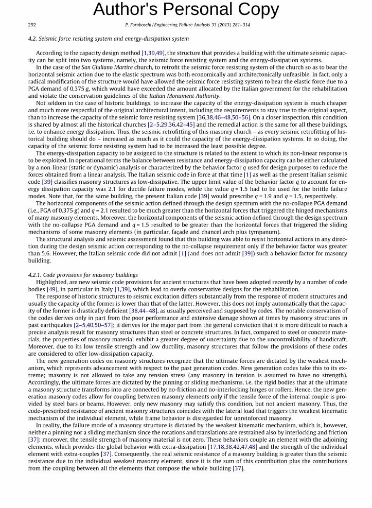
strength of materials, since the portal frame was unstable. In fact, as described above, the restraints of the portal frame weretwo rollers and two hinges, which could not prevent rigid body motions (Fig. 19). Thus, the fraction of the lateral forces thateach portal frame could share was limited by the overturning of the upright post (Fig. 20). Unfortunately, the upright postwas slender, and therefore the lateral resistance of the portal frame was marginal.
The large demand of lateral restraining force was the result of portal frames that provided the lateral resisting systemwith marginal contributions. The greater the lateral strength of the portal frame, the lower the demand for lateral restrainingforce. Thus, the retrofitting design was directed towards turning the portal frame from an unstable to a stable structure. Thegreater the number of reactions to resist the lateral load, the greater the lateral strength of the portal frame. Thus, the designattempted to obtain a fully restrained portal frame.
To this end, the base of each upright post had to be restrained against translation and rotation; moreover, the top of eachupright post had to be restrained against the relative rotation with respect to the crossbeam (Palladian truss). This implied tofix the upright post (i.e., the fictitious pier) at both ends. Accordingly, the base of each column had to be rigidly fixed to theground, and the top of the longitudinal wall had to be rigidly fixed to the end of the truss beam.
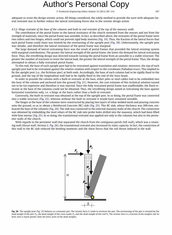
In order to provide the column with a built-in restraint at the base, either piles or steel cables had to be embedded intothe base of the column and anchored into the ground (Fig. 21). However, the cost estimate of this technical solution turnedout to be too expensive and therefore it was rejected. Since the fully restrained portal frame was unaffordable, the fixed re-straint at the base of the columns could not be obtained. Thus, the retrofitting design aimed at restraining the base againsthorizontal translation only, i.e. a hinge at the basis rather than a built-in restraint.
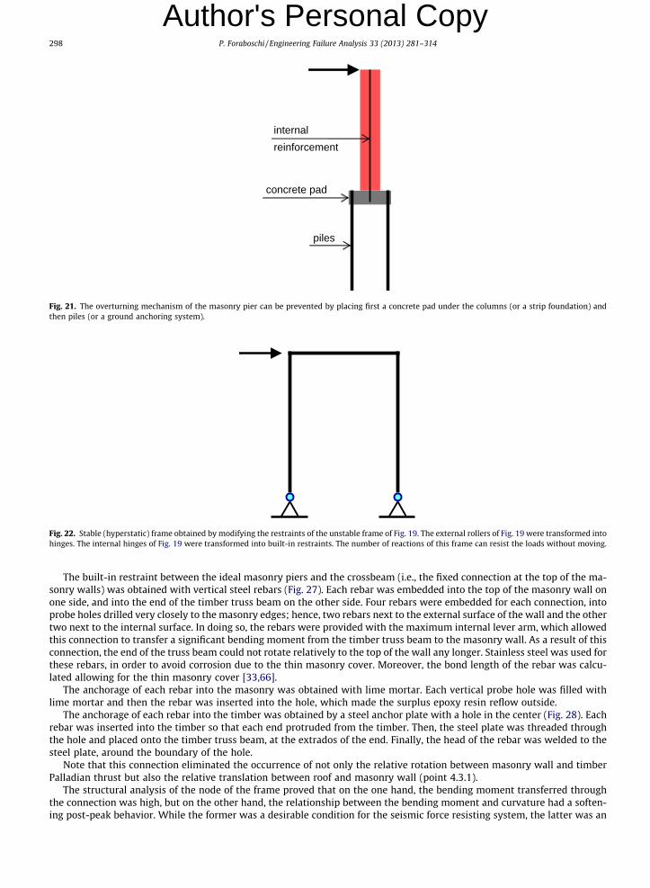
Conversely, the built-in restraint was obtained at the top of the upright post. In so doing, the portal frame was convertedinto a stable structure (Fig. 22), whereas without the built-in restraint it would have remained unstable.
The hinges at the base of the columns were constructed by placing two layers of rebar welded mesh and pouring concreteonto the ground, so as to obtain a Reinforced Concrete (RC) slab (Fig. 23). This RC slab, whose thickness was 200 mm, em-braced the base of the columns (Fig. 24). The slab was connected to the external masonry walls of the church. The connectionwas obtained by embedding the steel rebars of the RC slab into probe holes drilled into the masonry, which had been filledwith lime mortar (Fig. 25). In so doing, the translational restraint was applied not only to the columns but also to the perim-eter walls of the church.
With regards to the perimeter wall that separated the church from the contiguous parish (left wall), which was a retain-ing wall (thrust wall; Section 2; Fig. 26), the translational restraint also increased its static capacity. In fact, the connection ofthis wall to the RC slab reduced the bending moments and the shear forces that the soil thrust induced in the wall.
Fig. 20. The upright post (Fig. 19) behaves as a masonry pier. The seismic force Fs tends to overturn the pier. The overturning of the pier is resisted by thedead weight of the pier Pm, the dead weight of the cross-vaults Pv, and the dead weight of the roof Pc. The seismic force is a fraction of the weights, but itslever arm is much greater than the lever arms of the dead weights.
internal reinforcement
piles
concrete pad
Fig. 21. The overturning mechanism of the masonry pier can be prevented by placing first a concrete pad under the columns (or a strip foundation) andthen piles (or a ground anchoring system).
Fig. 22. Stable (hyperstatic) frame obtained by modifying the restraints of the unstable frame of Fig. 19. The external rollers of Fig. 19 were transformed intohinges. The internal hinges of Fig. 19 were transformed into built-in restraints. The number of reactions of this frame can resist the loads without moving.
298 P. Foraboschi / Engineering Failure Analysis 33 (2013) 281–314
Author's Personal Copy
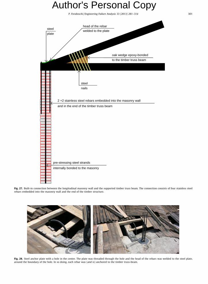
The built-in restraint between the ideal masonry piers and the crossbeam (i.e., the fixed connection at the top of the ma-sonry walls) was obtained with vertical steel rebars (Fig. 27). Each rebar was embedded into the top of the masonry wall onone side, and into the end of the timber truss beam on the other side. Four rebars were embedded for each connection, intoprobe holes drilled very closely to the masonry edges; hence, two rebars next to the external surface of the wall and the othertwo next to the internal surface. In doing so, the rebars were provided with the maximum internal lever arm, which allowedthis connection to transfer a significant bending moment from the timber truss beam to the masonry wall. As a result of thisconnection, the end of the truss beam could not rotate relatively to the top of the wall any longer. Stainless steel was used forthese rebars, in order to avoid corrosion due to the thin masonry cover. Moreover, the bond length of the rebar was calcu-lated allowing for the thin masonry cover [33,66].
The anchorage of each rebar into the masonry was obtained with lime mortar. Each vertical probe hole was filled withlime mortar and then the rebar was inserted into the hole, which made the surplus epoxy resin reflow outside.
The anchorage of each rebar into the timber was obtained by a steel anchor plate with a hole in the center (Fig. 28). Eachrebar was inserted into the timber so that each end protruded from the timber. Then, the steel plate was threaded throughthe hole and placed onto the timber truss beam, at the extrados of the end. Finally, the head of the rebar was welded to thesteel plate, around the boundary of the hole.
Note that this connection eliminated the occurrence of not only the relative rotation between masonry wall and timberPalladian thrust but also the relative translation between roof and masonry wall (point 4.3.1).
The structural analysis of the node of the frame proved that on the one hand, the bending moment transferred throughthe connection was high, but on the other hand, the relationship between the bending moment and curvature had a soften-ing post-peak behavior. While the former was a desirable condition for the seismic force resisting system, the latter was an
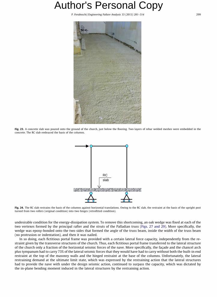
Fig. 23. A concrete slab was poured onto the ground of the church, just below the flooring. Two layers of rebar welded meshes were embedded in theconcrete. The RC slab embraced the basis of the columns.
RC slab
Fig. 24. The RC slab restrains the basis of the columns against horizontal translations. Owing to the RC slab, the restraint at the basis of the upright postturned from two rollers (original condition) into two hinges (retrofitted condition).
P. Foraboschi / Engineering Failure Analysis 33 (2013) 281–314 299
Author's Personal Copy
undesirable condition for the energy-dissipation system. To remove this shortcoming, an oak wedge was fixed at each of thetwo vertexes formed by the principal rafter and the struts of the Palladian truss (Figs. 27 and 29). More specifically, thewedge was epoxy-bonded onto the two sides that formed the angle of the truss beam, inside the width of the truss beam(no protrusion or indentation), and then it was nailed.
In so doing, each fictitious portal frame was provided with a certain lateral force capacity, independently from the re-straint given by the transverse structures of the church. Thus, each fictitious portal frame transferred to the lateral structureof the church only a fraction of the horizontal seismic forces of the nave. More specifically, the façade and the chancel archplus tympanum had to carry 73% of the lateral seismic forces that they would have had to carry without both the built-in endrestraint at the top of the masonry walls and the hinged restraint at the base of the columns. Unfortunately, the lateralrestraining demand at the ultimate limit state, which was expressed by the restraining action that the lateral structureshad to provide the nave with under the design seismic action, continued to surpass the capacity, which was dictated bythe in-plane bending moment induced in the lateral structures by the restraining action.
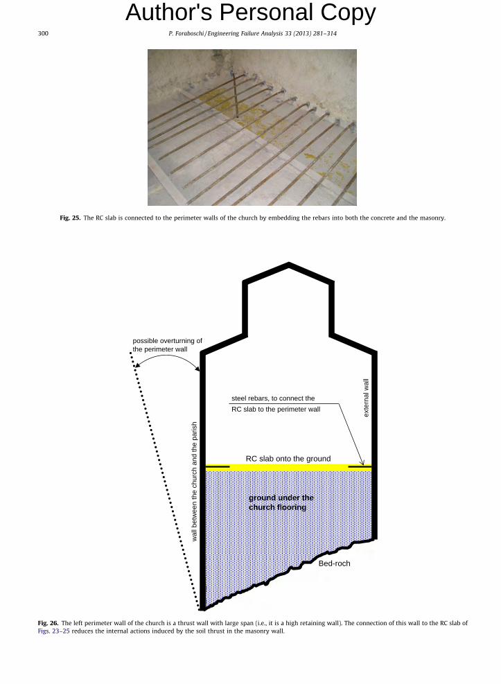
Fig. 25. The RC slab is connected to the perimeter walls of the church by embedding the rebars into both the concrete and the masonry.
RC slab onto the ground
steel rebars, to connect theRC slab to the perimeter wall
possible overturning of the perimeter wall
ground under the church flooring
exte
rnal
wal
l
wal
l bet
wee
n th
e ch
urch
and
the
paris
h
Bed-roch
Fig. 26. The left perimeter wall of the church is a thrust wall with large span (i.e., it is a high retaining wall). The connection of this wall to the RC slab ofFigs. 23–25 reduces the internal actions induced by the soil thrust in the masonry wall.
300 P. Foraboschi / Engineering Failure Analysis 33 (2013) 281–314
Author's Personal Copy
oak wedge epoxy-bonded to the timber truss beam
steelnails
2 +2 stainless steel rebars embedded into the masonry wall
and in the end of the timber truss beam
steel plate
pre-stressing steel strands
internally bonded to the masonry
head of the rebarwelded to the plate
Fig. 27. Built-in connection between the longitudinal masonry wall and the supported timber truss beam. The connection consists of four stainless steelrebars embedded into the masonry wall and the end of the timber structure.
Fig. 28. Steel anchor plate with a hole in the center. The plate was threaded through the hole and the head of the rebars was welded to the steel plate,around the boundary of the hole. In so doing, each rebar was (and is) anchored to the timber truss-beam.
P. Foraboschi / Engineering Failure Analysis 33 (2013) 281–314 301
Author's Personal Copy
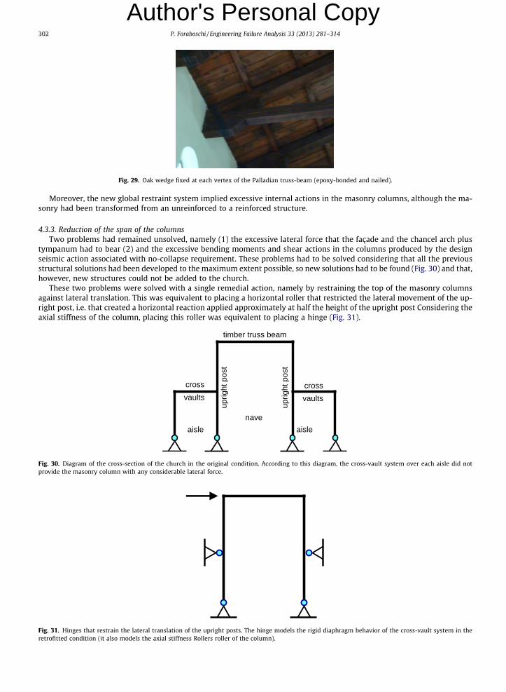
Fig. 29. Oak wedge fixed at each vertex of the Palladian truss-beam (epoxy-bonded and nailed).
302 P. Foraboschi / Engineering Failure Analysis 33 (2013) 281–314
Author's Personal Copy
Moreover, the new global restraint system implied excessive internal actions in the masonry columns, although the ma-sonry had been transformed from an unreinforced to a reinforced structure.
4.3.3. Reduction of the span of the columnsTwo problems had remained unsolved, namely (1) the excessive lateral force that the façade and the chancel arch plus
tympanum had to bear (2) and the excessive bending moments and shear actions in the columns produced by the designseismic action associated with no-collapse requirement. These problems had to be solved considering that all the previousstructural solutions had been developed to the maximum extent possible, so new solutions had to be found (Fig. 30) and that,however, new structures could not be added to the church.
These two problems were solved with a single remedial action, namely by restraining the top of the masonry columnsagainst lateral translation. This was equivalent to placing a horizontal roller that restricted the lateral movement of the up-right post, i.e. that created a horizontal reaction applied approximately at half the height of the upright post Considering theaxial stiffness of the column, placing this roller was equivalent to placing a hinge (Fig. 31).
naveaisleaisle
uprig
ht p
ost
cross vaults
crossvaults
timber truss beam
uprig
ht p
ost
Fig. 30. Diagram of the cross-section of the church in the original condition. According to this diagram, the cross-vault system over each aisle did notprovide the masonry column with any considerable lateral force.
Fig. 31. Hinges that restrain the lateral translation of the upright posts. The hinge models the rigid diaphragm behavior of the cross-vault system in theretrofitted condition (it also models the axial stiffness Rollers roller of the column).
P. Foraboschi / Engineering Failure Analysis 33 (2013) 281–314 303
Author's Personal Copy
The only way to obtain this restraint was to provide the roof of each aisle with the rigid diaphragm behavior [63–65]. Infact, the roof of the aisle was connected to the façade and chancel arch. Therefore, by virtue of the rigid diaphragm behavior,the top of the column was prevented from horizontally translating relatively to the façade and chancel arch (Figs. 31 and 32).In doing so, two favorable effects were obtained.
(1) The restraining forces that the façade and chancel arch plus tympanum transmitted at the height of the aisle roof hadapproximately half the lever arm of the restraining forces that they transmitted at the height of the nave roof. Thus,the former forces induced a much lower bending moment in the façade and chancel arch plus tympanum than thelatter forces. As a result, the lateral structures of the church could tolerate the restraining force.
(2) The bending moments and shear forces induced in the column by the restraining action could be tolerated by themasonry section of the columns.
Hence, owing to the new restraining system, the structures of the church satisfied the provisions of the Italian code [1] forthe no-collapse requirement.
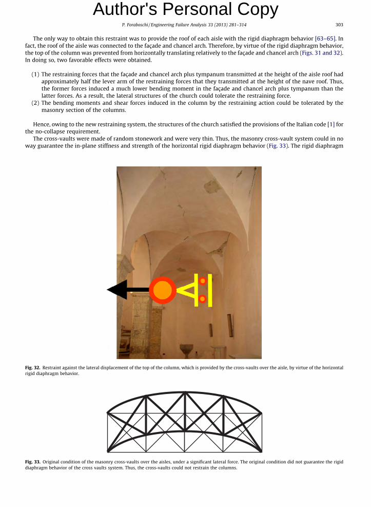
The cross-vaults were made of random stonework and were very thin. Thus, the masonry cross-vault system could in noway guarantee the in-plane stiffness and strength of the horizontal rigid diaphragm behavior (Fig. 33). The rigid diaphragm
Fig. 32. Restraint against the lateral displacement of the top of the column, which is provided by the cross-vaults over the aisle, by virtue of the horizontalrigid diaphragm behavior.
Fig. 33. Original condition of the masonry cross-vaults over the aisles, under a significant lateral force. The original condition did not guarantee the rigiddiaphragm behavior of the cross vaults system. Thus, the cross-vaults could not restrain the columns.
304 P. Foraboschi / Engineering Failure Analysis 33 (2013) 281–314
Author's Personal Copy
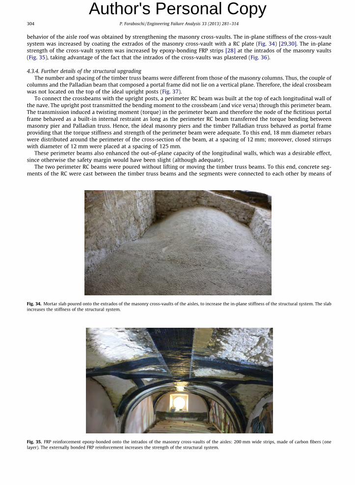
behavior of the aisle roof was obtained by strengthening the masonry cross-vaults. The in-plane stiffness of the cross-vaultsystem was increased by coating the extrados of the masonry cross-vault with a RC plate (Fig. 34) [29,30]. The in-planestrength of the cross-vault system was increased by epoxy-bonding FRP strips [28] at the intrados of the masonry vaults(Fig. 35), taking advantage of the fact that the intrados of the cross-vaults was plastered (Fig. 36).4.3.4. Further details of the structural upgradingThe number and spacing of the timber truss beams were different from those of the masonry columns. Thus, the couple of
columns and the Palladian beam that composed a portal frame did not lie on a vertical plane. Therefore, the ideal crossbeamwas not located on the top of the ideal upright posts (Fig. 37).
To connect the crossbeams with the upright posts, a perimeter RC beam was built at the top of each longitudinal wall ofthe nave. The upright post transmitted the bending moment to the crossbeam (and vice versa) through this perimeter beam.The transmission induced a twisting moment (torque) in the perimeter beam and therefore the node of the fictitious portalframe behaved as a built-in internal restraint as long as the perimeter RC beam transferred the torque bending betweenmasonry pier and Palladian truss. Hence, the ideal masonry piers and the timber Palladian truss behaved as portal frameproviding that the torque stiffness and strength of the perimeter beam were adequate. To this end, 18 mm diameter rebarswere distributed around the perimeter of the cross-section of the beam, at a spacing of 12 mm; moreover, closed stirrupswith diameter of 12 mm were placed at a spacing of 125 mm.
These perimeter beams also enhanced the out-of-plane capacity of the longitudinal walls, which was a desirable effect,since otherwise the safety margin would have been slight (although adequate).
The two perimeter RC beams were poured without lifting or moving the timber truss beams. To this end, concrete seg-ments of the RC were cast between the timber truss beams and the segments were connected to each other by means of
Fig. 34. Mortar slab poured onto the extrados of the masonry cross-vaults of the aisles, to increase the in-plane stiffness of the structural system. The slabincreases the stiffness of the structural system.
Fig. 35. FRP reinforcement epoxy-bonded onto the intrados of the masonry cross-vaults of the aisles: 200 mm wide strips, made of carbon fibers (onelayer). The externally bonded FRP reinforcement increases the strength of the structural system.

Fig. 36. Aisle after the structural work and the plastering of the intrados.
Fig. 37. The timber truss beam did not lie on the vertical plane of the two upright posts. Therefore, the timber truss beams were connected to the masonrypiers by means of a RC beams placed at the top of each perimeter wall.
P. Foraboschi / Engineering Failure Analysis 33 (2013) 281–314 305
Author's Personal Copy
rebars that crossed through the ends of the timber truss beams. The ends of the timber truss beams were protected from theconcrete by enveloping them with PVB sheets.
4.4. Damage limitation state
It is generally recognized that there is a relationship between interstory drift and different levels of damage in structuraland nonstructural elements [13,27,36,38,40–42,62]. In particular, the drift ratio (i.e., the drift divided by the story height be-tween the two floors) is a measure of the distortion of the structure; therefore, it can be used as a measure of expected
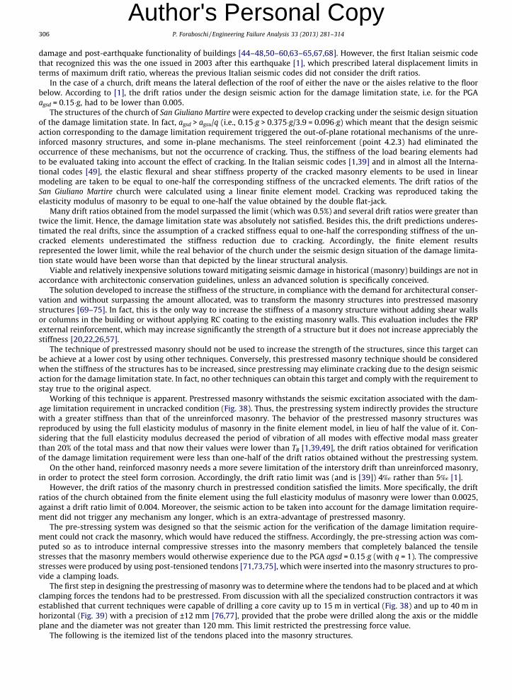
306 P. Foraboschi / Engineering Failure Analysis 33 (2013) 281–314
Author's Personal Copy
damage and post-earthquake functionality of buildings [44–48,50–60,63–65,67,68]. However, the first Italian seismic codethat recognized this was the one issued in 2003 after this earthquake [1], which prescribed lateral displacement limits interms of maximum drift ratio, whereas the previous Italian seismic codes did not consider the drift ratios.In the case of a church, drift means the lateral deflection of the roof of either the nave or the aisles relative to the floorbelow. According to [1], the drift ratios under the design seismic action for the damage limitation state, i.e. for the PGAagsd = 0.15�g, had to be lower than 0.005.
The structures of the church of San Giuliano Martire were expected to develop cracking under the seismic design situationof the damage limitation state. In fact, agsd > agsu/q (i.e., 0.15�g > 0.375�g/3.9 = 0.096�g) which meant that the design seismicaction corresponding to the damage limitation requirement triggered the out-of-plane rotational mechanisms of the unre-inforced masonry structures, and some in-plane mechanisms. The steel reinforcement (point 4.2.3) had eliminated theoccurrence of these mechanisms, but not the occurrence of cracking. Thus, the stiffness of the load bearing elements hadto be evaluated taking into account the effect of cracking. In the Italian seismic codes [1,39] and in almost all the Interna-tional codes [49], the elastic flexural and shear stiffness property of the cracked masonry elements to be used in linearmodeling are taken to be equal to one-half the corresponding stiffness of the uncracked elements. The drift ratios of theSan Giuliano Martire church were calculated using a linear finite element model. Cracking was reproduced taking theelasticity modulus of masonry to be equal to one-half the value obtained by the double flat-jack.
Many drift ratios obtained from the model surpassed the limit (which was 0.5%) and several drift ratios were greater thantwice the limit. Hence, the damage limitation state was absolutely not satisfied. Besides this, the drift predictions underes-timated the real drifts, since the assumption of a cracked stiffness equal to one-half the corresponding stiffness of the un-cracked elements underestimated the stiffness reduction due to cracking. Accordingly, the finite element resultsrepresented the lower limit, while the real behavior of the church under the seismic design situation of the damage limita-tion state would have been worse than that depicted by the linear structural analysis.
Viable and relatively inexpensive solutions toward mitigating seismic damage in historical (masonry) buildings are not inaccordance with architectonic conservation guidelines, unless an advanced solution is specifically conceived.
The solution developed to increase the stiffness of the structure, in compliance with the demand for architectural conser-vation and without surpassing the amount allocated, was to transform the masonry structures into prestressed masonrystructures [69–75]. In fact, this is the only way to increase the stiffness of a masonry structure without adding shear wallsor columns in the building or without applying RC coating to the existing masonry walls. This evaluation includes the FRPexternal reinforcement, which may increase significantly the strength of a structure but it does not increase appreciably thestiffness [20,22,26,57].
The technique of prestressed masonry should not be used to increase the strength of the structures, since this target canbe achieve at a lower cost by using other techniques. Conversely, this prestressed masonry technique should be consideredwhen the stiffness of the structures has to be increased, since prestressing may eliminate cracking due to the design seismicaction for the damage limitation state. In fact, no other techniques can obtain this target and comply with the requirement tostay true to the original aspect.
Working of this technique is apparent. Prestressed masonry withstands the seismic excitation associated with the dam-age limitation requirement in uncracked condition (Fig. 38). Thus, the prestressing system indirectly provides the structurewith a greater stiffness than that of the unreinforced masonry. The behavior of the prestressed masonry structures wasreproduced by using the full elasticity modulus of masonry in the finite element model, in lieu of half the value of it. Con-sidering that the full elasticity modulus decreased the period of vibration of all modes with effective modal mass greaterthan 20% of the total mass and that now their values were lower than TB [1,39,49], the drift ratios obtained for verificationof the damage limitation requirement were less than one-half of the drift ratios obtained without the prestressing system.
On the other hand, reinforced masonry needs a more severe limitation of the interstory drift than unreinforced masonry,in order to protect the steel form corrosion. Accordingly, the drift ratio limit was (and is [39]) 4‰ rather than 5‰ [1].
However, the drift ratios of the masonry church in prestressed condition satisfied the limits. More specifically, the driftratios of the church obtained from the finite element using the full elasticity modulus of masonry were lower than 0.0025,against a drift ratio limit of 0.004. Moreover, the seismic action to be taken into account for the damage limitation require-ment did not trigger any mechanism any longer, which is an extra-advantage of prestressed masonry.
The pre-stressing system was designed so that the seismic action for the verification of the damage limitation require-ment could not crack the masonry, which would have reduced the stiffness. Accordingly, the pre-stressing action was com-puted so as to introduce internal compressive stresses into the masonry members that completely balanced the tensilestresses that the masonry members would otherwise experience due to the PGA agsd = 0.15�g (with q = 1). The compressivestresses were produced by using post-tensioned tendons [71,73,75], which were inserted into the masonry structures to pro-vide a clamping loads.
The first step in designing the prestressing of masonry was to determine where the tendons had to be placed and at whichclamping forces the tendons had to be prestressed. From discussion with all the specialized construction contractors it wasestablished that current techniques were capable of drilling a core cavity up to 15 m in vertical (Fig. 38) and up to 40 m inhorizontal (Fig. 39) with a precision of ±12 mm [76,77], provided that the probe were drilled along the axis or the middleplane and the diameter was not greater than 120 mm. This limit restricted the prestressing force value.
The following is the itemized list of the tendons placed into the masonry structures.
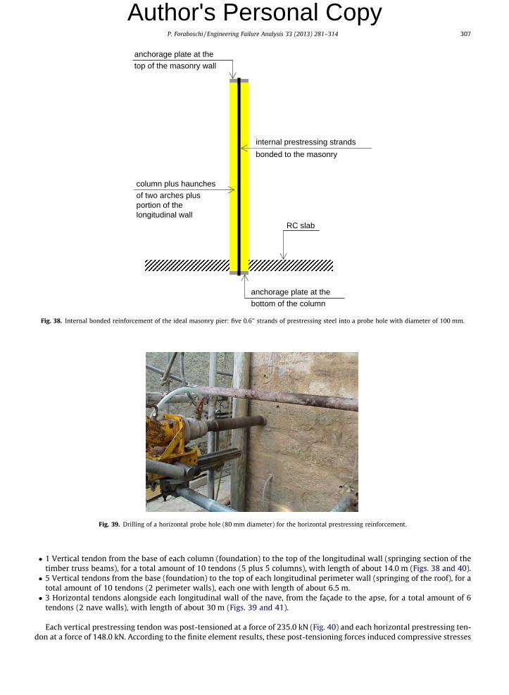
RC slab
internal prestressing strandsbonded to the masonry
anchorage plate at the top of the masonry wall
anchorage plate at the bottom of the column
column plus haunches of two arches plus portion of the longitudinal wall
Fig. 38. Internal bonded reinforcement of the ideal masonry pier: five 0.6’’ strands of prestressing steel into a probe hole with diameter of 100 mm.
Fig. 39. Drilling of a horizontal probe hole (80 mm diameter) for the horizontal prestressing reinforcement.
P. Foraboschi / Engineering Failure Analysis 33 (2013) 281–314 307
Author's Personal Copy
� 1 Vertical tendon from the base of each column (foundation) to the top of the longitudinal wall (springing section of thetimber truss beams), for a total amount of 10 tendons (5 plus 5 columns), with length of about 14.0 m (Figs. 38 and 40).� 5 Vertical tendons from the base (foundation) to the top of each longitudinal perimeter wall (springing of the roof), for a
total amount of 10 tendons (2 perimeter walls), each one with length of about 6.5 m.� 3 Horizontal tendons alongside each longitudinal wall of the nave, from the façade to the apse, for a total amount of 6
tendons (2 nave walls), with length of about 30 m (Figs. 39 and 41).
Each vertical prestressing tendon was post-tensioned at a force of 235.0 kN (Fig. 40) and each horizontal prestressing ten-don at a force of 148.0 kN. According to the finite element results, these post-tensioning forces induced compressive stresses

Fig. 40. Post-tensioned masonry: strands that compose the tendon, circular steel bearing plate, and anchorage system. The jack is tensioning one of the fivestrands that compose the vertical tendon.
Fig. 41. Horizontal prestressing reinforcement: the horizontal tendon is composed of three strands. Circular steel bearing plate.
308 P. Foraboschi / Engineering Failure Analysis 33 (2013) 281–314
Author's Personal Copy
that counterbalanced the tensile stresses due to the design seismic action associated with the damage limitation require-ment. In order to minimize the effects of the loss of prestress, the maximum allowable initial stress was applied to the pre-stressing steel; more specifically, the jacking stress minus initial losses reached 85% of the 0.1% proof-stress of prestressingsteel. Thus, the vertical tendon was designed so that the final value of the prestressing force was 235.0 kN and the horizontaltendon so that the final value was 148.0 kN (after the occurrence of masonry creep, and prestressing steel relaxation). Thisresult was obtained with a vertical tendon composed of 5 strands and a horizontal tendon composed of 3 strands (7-wirestrands having diameter of 0.600 � 15.2 mm and cross-sectional area of 140 mm2).
In order to accommodate the 5-strand tendon, the minimum diameter of the probe hole was 100 mm and in order toaccommodate the 3-strand tendon was 80 mm. Fortunately, these diameters respected the above-described constructionlimit of the probe hole which was of 120 mm. Accordingly, vertical probe holes having diameter of 100 mm and horizontalprobe holes having diameter of 80 mm were drilled along the axis of the columns and along the middle plane of the walls.
In order to avoid damage to the masonry, a rotary drilling machine was used rather a hammer drilling machine, althoughthe latter was faster than the former (Fig. 39). Each vertical probe hole was drilled at a velocity of about 0.75 m/h and eachhorizontal hole was drilled at a velocity of about 0.90 m/h at the beginning and 0.65 m/h at the end. Subsequently, the ver-tical and horizontal prestressing tendons were inserted into the masonry columns (Fig. 40) and walls Fig. 41.
Then, the tendons were tensioned by hydraulic jacks that reacted against the masonry member itself (Fig. 40). The jackwas attached to both ends of the horizontal tendons but only to the top end of the vertical tendons, since the bottom end wasnot easily accessible. More specifically, each strand that composed the tendon was tensioned by the jack, so as to obtain thenecessary fraction of the total prestressing force of the tendon.
The post-tensioning anchorage system that was used worked on the basis of wedge action on the wire ends (Fig. 42).When the strands were stretched by the jack, wedges were put in the wedge plate (cylinder). When the strands were re-leased, they took the wedges inside and were firmly held in position. A bearing plate was provided below each anchorageas the stresses passing through the anchorage were of a very high magnitude (Figs. 40–42). The bearing plate was designed
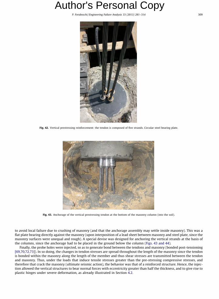
Fig. 42. Vertical prestressing reinforcement: the tendon is composed of five strands. Circular steel bearing plate.
Fig. 43. Anchorage of the vertical prestressing tendon at the bottom of the masonry column (into the soil).
P. Foraboschi / Engineering Failure Analysis 33 (2013) 281–314 309
Author's Personal Copy
to avoid local failure due to crushing of masonry (and that the anchorage assembly may settle inside masonry). This was aflat plate bearing directly against the masonry (upon interposition of a lead sheet between masonry and steel plate, since themasonry surfaces were unequal and rough). A special devise was designed for anchoring the vertical strands at the basis ofthe columns, since the anchorage had to be placed in the ground below the column (Figs. 43 and 44).
Finally, the probe holes were injected, so as to generate bond between the tendons and masonry (bonded post-tensioning[69,70,72,73]). In so doing, the changes in tendon stresses are spread throughout the length of the masonry since the tendonis bonded within the masonry along the length of the member and thus shear stresses are transmitted between the tendonand masonry. Thus, under the loads that induce tensile stresses greater than the pre-stressing compressive stresses, andtherefore that crack the masonry (ultimate seismic action), the behavior was that of a reinforced structure. Hence, the injec-tion allowed the vertical structures to bear normal forces with eccentricity greater than half the thickness, and to give rise toplastic hinges under severe deformation, as already illustrated in Section 4.2.

Fig. 44. Insertion of the bottom anchorage of a vertical prestressing tendon into the ground below the column.
Fig. 45. Façade of the San Giuliano Martire church at the end of the structural work (June 2007), a week after the May-27-2007 earthquake. Note that thecircular steel bearing plates had been modified, in compliance with an architectonic request of the Italian Monument authority.
310 P. Foraboschi / Engineering Failure Analysis 33 (2013) 281–314
Author's Personal Copy
5. 2007-Earthquake and 2011-earthquake: Full-scale verification
As mentioned in the introduction, the construction work began in August of 2005 and finished in June of 2007 (Fig. 45).The church was inaugurated on July 21st, 2007 (Fig. 46).
Two earthquakes have struck the building since the end of the structural work [78]. The first earthquake, registering amagnitude of 3.1 on the Richter scale, struck the building on May 27, 2007, just one and half month before the inaugurationof the church. This earthquake caused no damage to the church and the parish (no cracks), while it damaged almost all theother buildings of San Giuliano di Puglia, although some of them had been subjected to seismic retrofitting.
The second earthquake, registering a magnitude of 3.7, struck the building in 2011. In 2009, seismometers had beenplaced in that area. Thus, the ground motion of the 2011 earthquake was registered. The analysis of the recorded datashowed that this earthquake reached a PGA of 0.19�g, against a design PGA of 0.15�g for the seismic action to be taken intoaccount for the damage limitation requirement in compliance with the code in force at that time [1] and 0.113�g with thepresent code [39]. After this earthquake, the church was inspected and was found to have no damage or any other conditions.In particular, no cracks were found in the masonry walls, columns or vaults. On the contrary, the sacral furniture resting onthe ground suffered from significant damage (the earthquake caused the overturning of the altar).
The response of the San Giuliano Martire church to these two earthquakes proves that to prestress vertical masonry struc-tures is an effective technique for significantly increasing the stiffness of a masonry building.
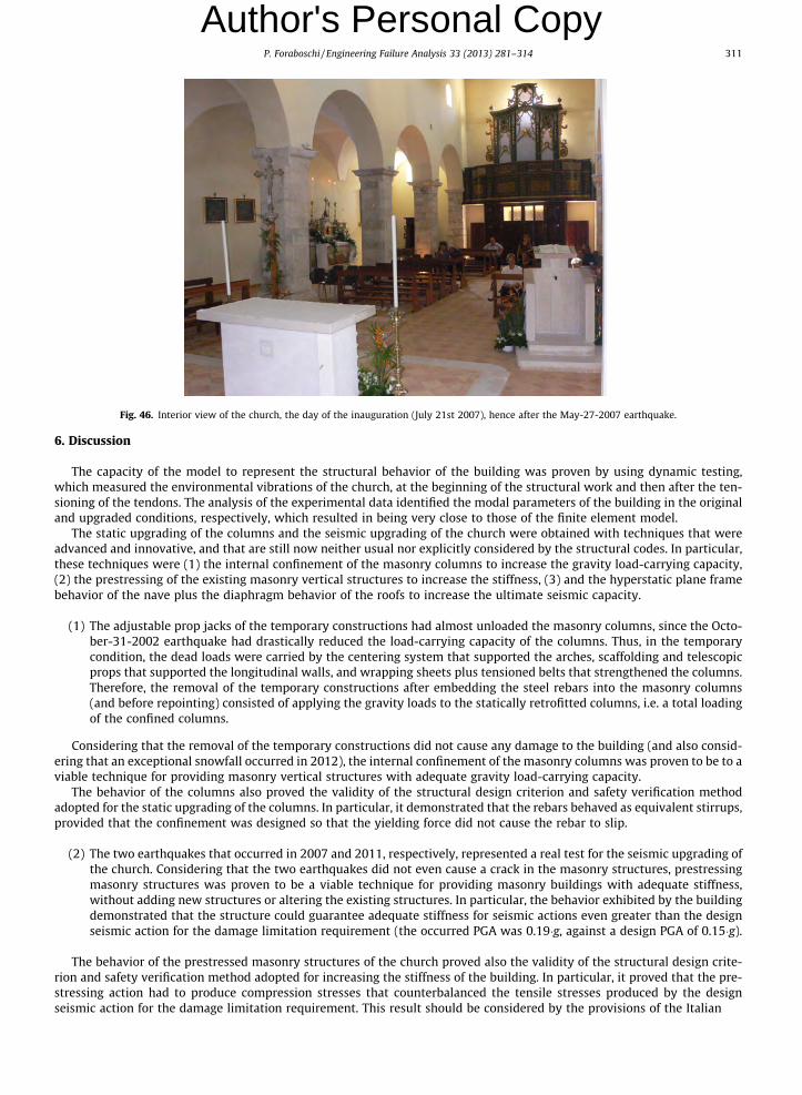
Fig. 46. Interior view of the church, the day of the inauguration (July 21st 2007), hence after the May-27-2007 earthquake.
P. Foraboschi / Engineering Failure Analysis 33 (2013) 281–314 311
Author's Personal Copy
6. Discussion
The capacity of the model to represent the structural behavior of the building was proven by using dynamic testing,which measured the environmental vibrations of the church, at the beginning of the structural work and then after the ten-sioning of the tendons. The analysis of the experimental data identified the modal parameters of the building in the originaland upgraded conditions, respectively, which resulted in being very close to those of the finite element model.
The static upgrading of the columns and the seismic upgrading of the church were obtained with techniques that wereadvanced and innovative, and that are still now neither usual nor explicitly considered by the structural codes. In particular,these techniques were (1) the internal confinement of the masonry columns to increase the gravity load-carrying capacity,(2) the prestressing of the existing masonry vertical structures to increase the stiffness, (3) and the hyperstatic plane framebehavior of the nave plus the diaphragm behavior of the roofs to increase the ultimate seismic capacity.
(1) The adjustable prop jacks of the temporary constructions had almost unloaded the masonry columns, since the Octo-ber-31-2002 earthquake had drastically reduced the load-carrying capacity of the columns. Thus, in the temporarycondition, the dead loads were carried by the centering system that supported the arches, scaffolding and telescopicprops that supported the longitudinal walls, and wrapping sheets plus tensioned belts that strengthened the columns.Therefore, the removal of the temporary constructions after embedding the steel rebars into the masonry columns(and before repointing) consisted of applying the gravity loads to the statically retrofitted columns, i.e. a total loadingof the confined columns.
Considering that the removal of the temporary constructions did not cause any damage to the building (and also consid-ering that an exceptional snowfall occurred in 2012), the internal confinement of the masonry columns was proven to be to aviable technique for providing masonry vertical structures with adequate gravity load-carrying capacity.
The behavior of the columns also proved the validity of the structural design criterion and safety verification methodadopted for the static upgrading of the columns. In particular, it demonstrated that the rebars behaved as equivalent stirrups,provided that the confinement was designed so that the yielding force did not cause the rebar to slip.
(2) The two earthquakes that occurred in 2007 and 2011, respectively, represented a real test for the seismic upgrading ofthe church. Considering that the two earthquakes did not even cause a crack in the masonry structures, prestressingmasonry structures was proven to be a viable technique for providing masonry buildings with adequate stiffness,without adding new structures or altering the existing structures. In particular, the behavior exhibited by the buildingdemonstrated that the structure could guarantee adequate stiffness for seismic actions even greater than the designseismic action for the damage limitation requirement (the occurred PGA was 0.19�g, against a design PGA of 0.15�g).
The behavior of the prestressed masonry structures of the church proved also the validity of the structural design crite-rion and safety verification method adopted for increasing the stiffness of the building. In particular, it proved that the pre-stressing action had to produce compression stresses that counterbalanced the tensile stresses produced by the designseismic action for the damage limitation requirement. This result should be considered by the provisions of the Italian

312 P. Foraboschi / Engineering Failure Analysis 33 (2013) 281–314
Author's Personal Copy
Monument authority [79](3) In masonry structures and especially in prestressed masonry structures, dissipative behavior implies visible damage,since it requires severe deformations that either crack or crush the masonry. The San Giuliano Martire church with-stood the 2007 and 2011 earthquakes without the occurrence of any damage, in particular without developing crack-ing or local crushing (no inelastic behavior). Thus, the structure resisted these earthquakes in the linear range, i.e.without dissipating energy by means of hysteretic behavior or other mechanisms.
The 2011 earthquake reached a PGA of 0.19�g; hence, the structure withstood seismic forces equal to those produced bythe elastic response spectrum with a PGA of 0.19�g. The seismic upgrading was designed to dissipate the fraction 1 � 1/3.9 = 0.74 of the design seismic action corresponding to the no-collapse requirement and to bear the force that derives fromthe elastic response spectrum with a PGA equal to the fraction 0.26 of the design PGA, i.e. the PGA 0.375�g/3.9 = 0.096�g.
Considering that the seismically upgraded structures withstood forces of almost double the forces that it was designed towithstand (0.19/0.096 = 1.98), the hyperstatic plane frame behavior of the nave plus the diaphragm behavior of the roofswere proven to be a viable technique for providing masonry buildings with adequate capacity to resist the ultimate seismicforces, i.e. to increase the capacity of the seismic force resisting system.
Moreover, this also proved the validity of the structural design criterion and safety verification method adopted to obtainhyperstatic frames and diaphragm behavior of the roofs of nave and aisles.
7. Conclusions
Prestressing masonry structures is the only way to increase the stiffness and the load-carrying capacity of a masonrybuilding, without adding new structures (shear walls or columns) or altering the original aspect of the surfaces (no coating).More specifically, high-tensile steel tendons (strands) have to be placed inside probe holes drilled along the axis of the ma-sonry structures, with steel bearing plates that anchor the tendons. Moreover, the probe holes have to be grouted so as tobond the steel tendons to the masonry (bonded pre-stressing reinforcement); in so doing, the masonry structure is also pro-vided with a significant capacity of bearing bending moments and shear forces.
This technique can be enhanced by embedding rebars into the masonry structures of the building. In so doing, the energydissipation capacity of the structure is increased, which decreases the seismic forces that the structure has to tolerate. Theserebars have to be bonded to the masonry using lime mortar (i.e., without cement).
The lateral capacity of historical churches is usually deficient, and the structures that compose the nave cannot survivethe design seismic action that corresponds to the ultimate limit state. The lateral capacity of the nave is dictated by theout-of-plane modes of failure of the masonry structures. In order to provide the nave with the capacity to withstand majorearthquakes, the timber elements of the roof have to be firmly connected to each other so as to obtain the rigid diaphragmbehavior. Moreover, the edges of the roof have to be connected to the façade, tympanum of the chancel arch and masonrywalls of the nave so as to prevent rigid body motions of the longitudinal structures relative to the transverse structures. Byvirtue of the rigid diaphragm behavior of the roof and the connection of the roof to all the vertical structures, the nave isrestrained against lateral translation.
Unfortunately, the façade and the cancel arch cannot usually tolerate the lateral forces transmitted by the nave duringsevere earthquakes, unless the church is small. Moreover, the internal actions in the columns of the nave are usually exces-sive. Nevertheless, there are two remedial actions that allow the structures to satisfy the requirements of the code. The firstremedial action is to connect the rotation of the top of the nave to the roof. In so doing, the horizontal forces transmitted bythe nave to the façade and chancel arch have a lower magnitude. The second remedial action is to also provide the roof of theaisles with the rigid diaphragm behavior. In doing so, the internal actions in the columns have a drastically lower magnitude.Moreover, the nave transmits the horizontal forces to the façade and chancel arch at a lower height, which implies lowerlever arms of the forces that dictate the rotating mechanisms.
These techniques were applied in the pilot design of the seismic repair and upgrading of the San Giuliano Martire church inthe town of San Giuliano di Puglia (Italy). The structural work has been tested by two significant earthquakes, whose demandsurpassed both the seismic action for the damage limitation requirement and the seismic forces for the no-collapse require-ment. Not so much as a crack appeared as a consequence of these earthquakes, which proves that these techniques are viablemeans for the seismic upgrading of historical buildings.
References
[1] OPCM 3274. Preliminary seismic subdivision of the national territories for local hazard definition and design of structures for earthquake resistance [inItalian: Primi elementi in materia di criteri generali per la classificazione sismica del territorio nazionale e di normative tecniche per le costruzioni inzona sismica]. Italy; 08.05.2003.
[2] Apostolopoulos C, Sotiropoulos P. Venetian churches of Lefkada, Greece Construction documentation and seismic behaviour ‘‘Virgin Mary of theStrangers’’. Constr Build Mater 2008;22(4):434–43.
[3] Barrios Padura A, Barrios Sevilla J, García Navarro J. Bearing capacity diagnosis of Santiago church (Jerez de la Frontera, Spain). Constr Build Mater2011;25(5):2519–27.
[4] Brandonisio G, Lucibello G, Mele E, De Luca A. Damage and performance evaluation of masonry churches in the 2009 L’aquila earthquake. Eng Fail Anal;February 9, 2013.

P. Foraboschi / Engineering Failure Analysis 33 (2013) 281–314 313
Author's Personal Copy
[5] Lourenço PB, Trujillo A, Mendes N, Ramos LF. Seismic performance of the St. George of the Latins church: lessons learned from studying masonry ruins.Eng Struct 2012;40:501–18.[6] Bigoni D, Noselli G. Localized stress percolation through dry masonry walls. Part I – Experiments. Eur J Mech A Solids 2010;29(3):291–8.[7] Bigoni D, Noselli G. Localized stress percolation through dry masonry walls. Part II – Modelling. Eur J Mech A Solids 2010;29(3):299–307.[8] Rekik A, Lebon F. Identification of the representative crack length evolution in a multi-level interface model for quasi-brittle masonry. Int J Solids Struct
2010;47(22–23):3011–21.[9] Calderoni B, Cecere G, Cordasco EA, Guerriero L, Lenza P, Manfredi G. Metrological definition and evaluation of some mechanical properties of post-
medieval Neapolitan yellow tuff masonry. J Cultural Heritage 2010;11(2):163–71.[10] Cecchi A. A model for composite brickwork-like materials based on discrete element procedure: sensitivity to different staggered tiers. Compos: Mech
Comput Appl Int J 2012;3(1):19–34.[11] Corradi M, Tedeschi C, Binda L, Borri A. Experimental evaluation of shear and compression strength of masonry wall before and after reinforcement:
deep repointing. Constr Build Mater 2008;22(4):463–72.[12] Marques LM, Chastre C, Vasconcelo G. Modelling the compressive mechanical behaviour of granite and sandstone historical building stones. Constr
Build Mater 2012;28(1):372–81.[13] Najafgholipour MA, Maheri MR, Lourenço PB. Capacity interaction in brick masonry under simultaneous in-plane and out-of-plane loads. Constr Build
Mater 2013;38(1):619–26.[14] Oliveira DV, Lourenço PB, Roca P. Cyclic behaviour of stone and brick masonry under uniaxial compressive loading. Mater Struct 2006;39(2):247–57.[15] Ewing BD, Kowalsky MJ. Compressive behavior of unconfined and confined clay brick masonry. ASCE J Struct Eng 2004;130(4):650–61.[16] Ghiassi B, Soltani M, Tasnimi AA. A simplified model for analysis of unreinforced masonry shear walls under combined axial, shear and flexural loading.
Eng Struct 2012;42:396–409.[17] Medeiros P, Vasconcelos G, Lourenço PB, Gouveia J. Numerical modelling of non-confined and confined masonry walls. Constr Build Mater
2013;41:968–76.[18] Tena-Colunga A, Juárez-Ángeles A, Salinas-Vallejo VH. Cyclic behavior of combined and confined masonry walls. Eng Struct 2009;31(1):240–59.[19] van Zijl G PAG. Modeling masonry shear-compression: role of dilatancy highlighted. ASCE, J Eng Mech 2004;130(11):1289–96.[20] Ascione L, Feo L, Fraternali F. Load carrying capacity of 2D FRP/strengthened masonry structures. Compos B Eng 2005;36(8):619–26.[21] Biolzi L, Ghittoni C, Fedele R, Rosati G. Experimental and theoretical issues in FRP-concrete bonding. Constr Build Mater 2013;41(4):182–90.[22] D’Ambrisi A, Focacci F, Caporale A. Strengthening of masonry-unreinforced concrete railway bridges with PBO-FRCM materials. Compos Struct
2013;102:193–204.[23] Faella C, Martinelli E, Camorani G, Aiello MA, Micelli F, Nigro E. Masonry columns confined by composite materials: design formulae. Compos B Eng
2011;42(4):705–16.[24] Foraboschi P. Shear strength computation of reinforced concrete beams strengthened with composite materials. Compos: Mech Comput Appl Int J
2012;3(3):227–52.[25] Foraboschi P. Predictive multiscale model of delayed debonding for concrete members with adhesively bonded external reinforcement, Compos: Mech
Comput Appl Int J 2012;3(4):307–29.[26] Foraboschi P, Vanin A. New methods for bonding FRP strips onto masonry structures: experimental results and analytical evaluations. Compos: Mech
Comput Appl Int J 2013;4(1):1–23.[27] Gabor A, Bennani A, Jacquelin E, Lebon F. Modelling approaches of the in-plane shear behaviour of unreinforced and FRP strengthened masonry panels.
Compos Struct 2006;74(3):277–88.[28] Muciaccia G, Biolzi L. Thermal degradation of fiber reinforced extruded materials. Fire Saf J 2012;49(4):89–99.[29] Pineda P, Robador MD, Perez-Rodrigue JL. Characterization and repair measures of the medieval building materials of a Hispanic-Islamic construction.
Constr Build Mater 2013;41(4):612–33.[30] Sandoval C, Roca P. Study of the influence of different parameters on the buckling behaviour of masonry walls. Constr Build Mater 2012;35:888–99.[31] D’Ambrisi A, Feo L, Focacci F. Experimental and analytical investigation on bond between Carbon-FRCM materials and masonry. Compos B Eng
2013;46:15–20.[32] Biolzi L. Evaluation of compressive strength of masonry walls by limit analysis. ASCE J Struct Eng 1988;114(10):2179–89.[33] Lin Z, Zhao J, Petersen D. Failure analysis of anchors in shear under simulated seismic loads. Eng Fail Anal 2013;31:59–67.[34] Thanoon WA, Alwathaf AH, Noorzaei J, Jaafar MS, Abdulkadir MR. Nonlinear finite element analysis of grouted and ungrouted hollow interlocking
mortarless block masonry system. Eng Struct 2008;30(6):1560–72.[35] Abrams D, Smith T, Lynch J, Franklin S. Effectiveness of rehabilitation on seismic behavior of masonry piers. ASCE J Struct Eng 2007;133(1):32–43.[36] Bruneau M. State-of-art report on the seismic performance of unreinforced masonry buildings. J Struct Eng, ASCE 1994;120(1):230–51.[37] Foraboschi P. Coupling effect between masonry spandrels and piers. Mater Struct 2009;42(3):279–300.[38] Griffith MC, Vaculik J, Lam NTK, Wilson J, Lumantarna E. Cyclic testing of unreinforced masonry walls in two-way bending. Earthquake Eng Struct
Dynam 2000;29(12):1797–813.[39] DM. New technical standard on constructions [in Italian: nuove Norme Tecniche sulle Costruzioni]; 16.01.2008.[40] Kwon OS, Kim E. Case study: analytical investigation on the failure of a two-story RC building damaged during the 2007 Pisco-Chincha earthquake. Eng
Struct 2010;32(7):1876–87.[41] Lourenço PB, Roque JA. Simplified indexes for the seismic vulnerability of ancient masonry buildings. Constr Build Mater 2006;20(4):200–8.[42] Lourenço PB, Krakowiak KJ, Fernandes FM, Ramos LF. Failure analysis of Monastery of Jerónimos, Lisbon: how to learn from sophisticated numerical
models. Eng Fail Anal 2007;14(2):280–300.[43] Shariq M, Abbas H, Irtaza H, Qamaruddin M. Influence of openings on seismic performance of masonry building walls. Build Environ
2008;43(7):1232–40.[44] Bayraktar A, CoS�kun N, Yalçin A. Damages of masonry buildings during the July 2, 2004 Dogubayazıt (Agrı) earthquake in Turkey. Eng Fail Anal
2007;14(1):147–57.[45] Çakmak AS�, Moropoulou A, Mullen CL. Interdisciplinary study of dynamic behavior and earthquake response of Hagia Sophia. Soil Dynam Earthquake
Eng 1995;14(2):125–33.[46] Klingne RE. Behavior of masonry in the Northridge (US) and Tecomán-Colima (Mexico) earthquakes: lessons learned, and changes in US design
provisions. Constr Build Mater 2006;20(4):209–19.[47] Seible F, Priestley MJN, Kingsley GR, Kürkchübasche AG. Seismic response of full-scale five-story reinforced-masonry building. ASCE J Struct Eng
1994;120(3):925–46.[48] Sucuoglu H, Erberik A. Performance evaluation of a three-storey unreinforced masonry building during the 1992 Erzincan earthquake. Earthquake Eng
Struct Dynam 1997;26(3):319–36.[49] EN1998-1:2004. Design of structures for earthquake resistance. General rules, seismic actions and rules for buildings. Eurocode 8. ISBN 058045872-5;
Committee reference B/525/8. 232 pp.[50] Gonen H, Dogan M, Karacasu M, Ozbasaran H, Gokdemi H. Structural failures in refrofit historical murat masonry arch bridge. Eng Fail Anal, in press
[online March 7, 2013].[51] Marco S. Recognition of earthquake-related damage in archaeological sites: examples from the Dead Sea fault zone. Tectonophysics 2008;453:148–56.[52] Romão X, Costa AA, Paupério E, Rodrigues H, Vicente R, Varum H, Costa A. Field observations and interpretation of the structural performance of
constructions after the 11 May 2011 Lorca earthquake. Eng Fail Anal, in press [online February 9, 2013].
314 P. Foraboschi / Engineering Failure Analysis 33 (2013) 281–314
Author's Personal Copy
[53] Sayın E, Yön B, Calayır Y, Karaton M. Failures of masonry and adobe buildings during the June 23, 2011 Maden-(Elazıg) earthquake in Turkey. Eng FailAnal [online November 5, 2012].[54] Sengel HS, Dogan M. Failure of buildings during Sultandagi Earthquake. Eng Fail Anal, in press [online October 7, 2012].[55] Tapan M, Comert M, Demir C, Sayan Y, Orakcal K, Ilki A. Failures of structures during the October 23, 2011 Tabanlı (Van) and November 9, 2011 Edremit
(Van) earthquakes in Turkey. Eng Fail Anal, in press [online Februray 27, 2013].[56] Tianyi Y, Moon FL, Leon RT, Kahn LF. Analyses of a two-story unreinforced masonry building. ASCE J Struct Eng 2006;132(5):653–62.[57] Willis CR, Yang Q, Seracino R, Griffith MC. Damaged masonry walls in two-way bending retrofitted with vertical FRP strips. Constr Build Mater
2009;23(4):1591–604.[58] Belmouden Y, Lestuzzi P. An equivalent frame model for seismic analysis of masonry and reinforced concrete buildings. Constr Build Mater
2009;23(1):40–53.[59] Branco M, Guerreiro LM. Seismic rehabilitation of historical masonry buildings. Eng Struct 2011;33(5):1626–34.[60] Juhásová E, Sofronie R, Bairrão R. Stone masonry in historical buildings – ways to increase their resistance and durability. Eng Struct
2008;30(8):2194–205.[61] Paret TF, Freeman SA, Searer GR, Hachem M, Gilmartin UM. Using traditional and innovative approaches in the seismic evaluation and strengthening of
a historic unreinforced masonry synagogue. Eng Struct 2008;30(8):2114–26.[62] Lee JS, Pande GN, Kralj B. A comparative study on the approximate analysis of masonry structures. Mater Struct 1998;31(7):473–9.[63] Kim SC, White DW. Nonlinear analysis of a one-story low-rise masonry building with a flexible diaphragm subjected to seismic excitation. Eng Struct
2004;26(14):2053–67.[64] Tena-Colunga A, Abrams DP. Seismic behavior of structures with flexible diaphragms. ASCE J Struct Eng 1996;122(4):439–45.[65] Paquette J, Bruneau M. Pseudo-dynamic testing of unreinforced masonry building with flexible diaphragm and comparison with existing procedures.
Constr Build Mater 2006;20(4):220–8.[66] van der Meer LJ, Martens DRW, Vermeltfoort AT. UPT rectangular and flanged shear walls of high-strength CASIEL-TLM masonry: experimental and
numerical push-over analysis. Eng Struct 2013;49:628–42.[67] Eslami A, Ronagh HR, Mahini SS, Morshed R. Experimental investigation and nonlinear FE analysis of historical masonry buildings – a case study.
Constr Build Mater 2012;35:251–60.[68] Masia MJ, Kleeman PW, Melchers RE. Modeling soil/structure interaction for masonry structures. ASCE J Struct Eng 2004;130(4):641–9.[69] Baqi A, Bhandari NM, Trikha DN. Experimental study of prestressed masonry flexural elements. ASCE J Struct Eng 1999;125(3):245–54.[70] Baqi A, Bhandari NM. Postcracking behavior of prestressed masonry in flexure. ASCE J Struct Eng 2007;133(4):507–18.[71] D’Ambrisi A, Feo L, Focacci F. Masonry arches strengthened with composite unbonded tendons. Compos Struct 2013;98:323–9.[72] Ma R, Jiang L, He M, Fang C, Lian F. Experimental investigations on masonry structures using external pre-stressing techniques for improving seismic
performance. Eng Struct 2012;42(9):297–307.[73] Popehn JRB, Schultz AE, Drake CR. Behavior of slender, posttensioned masonry walls under transverse loading. ASCE J Struct Eng
2007;133(11):1541–50.[74] Wight GD, Ingham JM. Tendon stress in unbonded posttensioned masonry walls at nominal in-plane strength. ASCE J Struct Eng 2008;134(6):938–46.[75] Yang KH, Joo DB, Sim JI, Kang JH. In-plane seismic performance of unreinforced masonry walls strengthened with unbonded prestressed wire rope
units. Eng Struct 2012;45:449–59.[76] Mukherjee D, Rao BN, Prasad AM. Global sensitivity analysis of unreinforced masonry structure using high dimensional model representation. Eng
Struct 2011;33(4):1316–25.[77] Popehn JRB, Schultz AE. Influence of imperfections on the out-of-plane flexural strength of post-tensioned masonry walls. Constr Build Mater
2013;41:942–9.[78] Istituto Nazionale di Geofisica e Vulcanologia. Parametric catalogue of the Italian earthquakes and Italian Seismic database; December 2011 [in Italian:
Catalogo Parametrico dei Terremoti Italiani e DataBase Macrosismico Italiano].[79] DPCM. Instructions for estimating and mitigating the seismic risk of cultural buildings; 26.02.2011 [in Italian: Valutazione e riduzione del rischio
sismico del patrimonio culturale].