p. anjana 1* j. electrical systems 13-1 (2017): 131-142...
TRANSCRIPT
* Corresponding author: Pradeep Anjana, Research Scholar Department of Electrical Engineering, MNIT Jaipur,
India, E-mail: [email protected] 1 Research Scholar, Department of Electrical Engineering, MNIT Jaipur, India 2 Faculty of Electrical Engineering, Department of Electrical Engineering, MNIT Jaipur, India
Copyright © JES 2017 on-line : journal/esrgroups.org/jes
P. Anjana1*
,
A. Kumar1,
N. Gupta2,
V. Gupta2,
H. P. Tiwari2
J. Electrical Systems 13-1 (2017): 131-142
Regular paper
Optimization Based Shunt APF Controller
to Mitigate Reactive Power, Burden of
Neutral Conductor, Current Harmonics
and Improve cosɸ
JES
Journal of Journal of Journal of Journal of Electrical Electrical Electrical Electrical SystemsSystemsSystemsSystems
This paper presents a Modified Gravitational Search Algorithm (MGSA) to improve the performance of PI controller in varying load condition. The proposed approach is capable of mitigating reactive power, neutral current, source current THD and significant improvement in power factor nearly unity (0.997). The DC link voltage across the capacitor is controlled by PI controller which is deciding the performance of shunt APF. Hence, the robust optimization technique based integral time square error (ITSE) with consideration of weight factor (α & β), maximum overshoot (|∆vn|) and setling timet − t, is providing the optimum solution of Kp & Ki. The robustness of proposed objective function and algorithm compared with GSA based three other error criterion techniques. The efficiency of the proposed controller has been tested over nonlinear and unbalance loading condition. The performance of ITSE based MGSA-PI controller is batter then other three error criterion techniques. The values of THD are below the mark of 5% specified in IEEE-519 standard.
Keywords: Modified Gravitational Search Algorithm (MGSA), Integral Time Squared Error (ITSE),
Shunt APF, Unity Power Factor (UPF), Total Harmonic Distortion (THD).
Article history: Received 1 June 2016, Accepted 11 January 2017
1. INTRODUCTION
From the past fifty years, the power quality pollution problem had been observed and
tried to overcome the problem with the implementation of different techniques day-by-day
[1]. At present every consumer is aware of power consumption and loss of power due to
polluting loads. The power electronics based equipment are largely used in the present
distribution system and these equipment are largely used semiconductor switches in the
circuit; hence these switching losses create a problem in electric utility and deviate
sinusoidal waveform. This deviation in sine wave is called as distortion and equipment are
known as a non-linear load which leads to harmonic distortion. The non-linear loads are
adjustable speed drives, arc furnaces, air conditioners, battery chargers, copier machines,
computers, frequency converters, medical equipment, switch-mode power supplies,
printers, uninterrupted power supplies, welding machines and x-ray equipment [2]. These
harmonic currents degraded the quality of power and interact adversely with a wide range
of power system equipment causing additional losses, overheating, overloading,
interference with telecommunication networks and also results in erroneous readings in
watt-hour and demand meters [3].

P. Anjana et al: Optimisation Based Shunt APF Controller to Mitigate Reactive Power...
132
The evolution of different compensation techniques to remove the effect of the
semiconductor switches from utility have been allowing a broader classification of the
passive, active and hybrid power filter in power systems [4]-[7]. The merits and demerits of
these methods are well presented in the literature [8]. One of the cornerstones of the shunt
APF is its control scheme strategy. The popular reference current generation strategies are
as unit template technique (UVT), power balance theory, I cosɸ algorithm, current
synchronous detection, PQ theory, SRF theory etc. One of the techniques is the DC link
voltage control by closed-loop PI controller with UVT which is quite simple and practically
used because of less number of sensors and switches used. The reference signal of the
closed-loop feedback control method could be constant DC voltage which compares with
DC link voltage of the capacitor. The useful information carried by the PI output signal is
its wave shape rather than the place where it comes from.
The PI controller tuning is based on subspace estimation methods and prediction error
estimation methods but they have some merits and demerits [8]. The subspace estimation
methods are discussed as Process Reaction Curve method firstly proposed by Ziegler and
Nichols for open loop and closed loop system [9], Relay method proposed by Astrm and
Hagglund in 1995 [10], Tyreus-Luyben's method is proposed in 1997, Hagglund and
Astrm's Robust tuning method, Skogestad’s Model-based method and Setpoint Overshoot
method etc [11]-[13]. Although these methods are widely used for tuning problems, but the
manual estimation of PI parameters makes false tuning of PI. Others are prediction error
estimation methods which are more popular in a present scenario. These methods are based
on optimization problem. In that optimization series following methods are available
Genetic Algorithm (GA) based PI, Particle Swarm Optimization (PSO) based PI, act colony
optimization (ACO) based PI and fuzzy logic based PI and bacteria foraging optimization
(BFO) based PI tuning etc [14]-[17]. The PSO is also an evolutionary computation
technique that simulates the social behavior of a swarm of birds or school of fish. The main
aspect of this technique is that the size and nonlinearity of the problem do not largely affect
the solution.
In this paper, a modified GSA-PI is executed for gain scheduling of PI controller to
minimize the error between the original DC link signal and the signal reference from the
estimated parameters during the estimation process. The MGSA is presented for real-time
self-tuning parameters, with Integral Time Square Error (ITSE) as an objective function.
The model is simulated to show the performance of the proposed controller whether the
sudden load change in micro grid under load change condition with the aim to study
dynamic performance of the system.
This paper is organized as follows: In section II, proposed shunt APF principle, while
section III describes the MGSA-PI controller. In section IV, the results and analysis with a
component of the system under steady state condition are illustrated. Finally, conclusions
out of the results will be shown in section V.
2. PROPOSED SAPF SCHEME AND ITS PRINCIPLE
The proposed topology of the SAPF is consists of a three-phase four wire based current
controlled voltage-source inverter, a second-order low-pass filter with voltage feedback

J. Electrical Systems 13-1 (2017): 131-142
133
loop as shown in Figure 1. Domestic consumers are using a large number of single-phase
loads which are connected with one of the three-phases with neutral wire, so excessive
neutral current will flow and cause reactive power burden and unbalance in the system. To
overcome these problems four-wire active filters are developed [6]-[7]. They are classified
as capacitor midpoint four-wire, four pole four-wire and three-bridge four-wire shunt active
filter. Figure 1 shows four-pole switch type SAPF consists of four-leg VSI; three-legs are
required to compensate the three-phase currents and one-leg needed to compensate the
neutral current. The four-leg VSI consists eight IGBT switches and an energy storage
capacitor. The indirect process is comparing with the modified controller and concludes the
better feasible solution with practical implementation. The shunt-connected APF shows the
characteristics similar to STATCOM (reactive power compensator of power transmission
system) when used with self-controlled dc bus.
The schematic diagram of SAPF shown in Figure 1, mitigates harmonics from the
current waveform by injecting equal and opposite current component. SAPF operated as
current source injects harmonics generated by load but in phase opposition (i.e 180o phase
shift). As a consequence the current harmonics in the load are canceling out by SAPF. This
principle is considered for all type of non-linear loads. Harmonic distortion is seen in both
types of waveforms due to electronic and non-linear loads. But it is evident that voltage
harmonics are produced due to current harmonics only, so we have to mitigate only current
harmonics from the supply to remove harmonic pollution from the system. That’s why
estimation of reference current is required [18].
3Phase &
1 Phase
Non-Linear
LoadUtility
Lc
Cdc
4 Leg IGBT Module
vavbvc
isa
isb
isc
in
iLa
iLb
iLc
ica
icb
iccicn
PCC
Controller
with
Control Algorithm
is iC
vs
P1
P8
Figure 1. Proposed model of SAPF
For these purposes most applications requiring dynamic performance, pulse width
modulation is the most commonly used for APF. Here hysteresis current controller
technique applied to control the VSI for consists of chopping the dc bus voltage to produce
an AC voltage of an arbitrary waveform. Gyugyi and Strycula [19] first introduced the
concept of shunt active power filter. The controllers of shunt active power filters
determines the compensating reference current in real time and force a power converter to

P. Anjana et al: Optimisation Based Shunt APF Controller to Mitigate Reactive Power...
134
synthesize it correctly so that the filtering can be choosy and adaptive. Harmonic currents
are produced mainly because of nonlinear loads and harmonic voltages in power system.
Figure 2 summarizes the basic principle of SAPF. A non-linear load draws a
fundamental current component I and load harmonic current component I from
the utility. Harmonic currents I flows through the power system, it produces a utility
harmonic voltage drop (V) equal to X. I, that degenerates the load terminal voltage
(V). However, SAPF with shunt current compensation also draws an additional harmonic
current I from the utility. So this I further create a voltage drop X. I to keep the V sinusoidal and equal to V − X. I, hence, the capacitor is charging/discharging and in
this condition, the harmonic voltage components cancel each other, so that V is kept
sinusoidal.
XL
Zapf
(ILF+ISh)pcci
θ
(ISh-ILh)apfi
θ
apfzθ
Vapf apfvθ
PCC
(ILF+ILh)
ILh
ISh
(VSf+VSh)pccv
θ
VSf
Liθ
VT Lvθ
Utility Source SAPF Non-Linear Load
Figure 2. Principle of Shunt Current Compensation
An SAPF can compensate both harmonic currentsI&I when system impedance is
high. However, the principle function of an SAPF is to restrict the load harmonic current at
PCC, hindering its infiltration into the power system. In order to achieve these objectives, a
Unit Vector Template (UVT) based indirect power control method, indirect PQ method is
proposed with and MGSA-PI controller. The three main parameters: L, V, and C are
referred from[20]-[21]. From Figure 2, the instantaneous source currents and source
voltage can be written as
"i t = I + I + Isin ωtand v t = V sin ωt * 1
A study of the nonlinear load has shown that the utility phase current will have a
fundamental component with the presence of harmonic components (in the case of
nonlinear load) which can be represented as:
J. Electrical Systems 13-1 (2017): 131-142
135
"i t = , I-
.-/0 sinnωt + φ-
or = I0 sinωt + φ0 + , I- sinnωt + φ- .
-/4 or = I0 sin ωt . cos φ0 + I0 cos ωt . sin φ0 + , I- sinnωt + φ-.
-/4
67777877779
2
Where I0&I- is the peak value of the fundamental and nth harmonic component of load current φ0&φ- is the phase angle of the fundamental and harmonic component of load current I;t = I0 sin ωt . cos φ0= Active instantaneous fundamental load current I<t = I0 cos ωt . sin φ0= Reactive instantaneous fundamental load current I=t= ∑ I- sinnωt + φ-.-/4 = Harmonic instantaneous load current
The load power can be calculated as
"
pt = v t × i t or= V sin ωt × AI0 sin ωt . cos φ0 + I0 cos ωt . sin φ0
+ , I- sinnωt + φ-.-/4
Bor= VI0 sin4 ωt . cos φ0 + VI0 sin ωt. sin φ0 . cos ωt
+V sin ωt , I- sinnωt + φ-.-/4or= P;t + P<t + P=t
6777778777779
3
Where P;t = VI0 sin4 ωt . cos φ0 = Instantaneous active power drawn by the load P<t = VI0 sin ωt sin φ0 cos ωt = Instantaneous reactive power demand of the load P=t = V sin ωt ∑ I- sinnωt + φ-.-/4 = Instantaneous harmonic power of the load
In the system, the reactive power is circulated between the phases before compensation.
The SAPF compensator provides reactive power compensation. The utility will be liable
only for the real power flow between utility and load [22]. The real power and current
supplied by the utility during the compensation can be expressed as:

P. Anjana et al: Optimisation Based Shunt APF Controller to Mitigate Reactive Power...
136
"P;t = VI0 sin4 ωt . cos φ0 = v t. I0 cos φ0 . sin ωtorI0 cos φ0 = P;tv t sin ωt = VI0 sin4 ωt . cos φ0V sin ωt . sin ωt 689 4
Therefore, the peak value of active fundamental component of utility current is
represented as IFt = I0 cos φ0 5
In a practical scenario, the current controlled VSI is also consumed some power in the
form of switching, conducting and system leakage losses, which has to be supplied by the
utility. So total peak current supplied by utility after compensation is given as iH = IF + I IJKK 6
Where, iH= peak current supplied by utility after compensation and I IJKK= total loss
current of the system supplied by the utility.
After compensation, the flow of the loss component of current is between the utility and
the SAPF, rather than total harmonic and reactive power of the load is supplied by the
SAPF. So there is no harmonic component in the utility current. This makes the utility
current to be in phase with the utility voltage. Therefore, the total instantaneous utility
current including losses after compensation will be: i ∗t = iHsinωt 7
Therefore, the injected current of SAPF will be given as it = I + I + I sinωt − i∗ t 8
So it is necessary to analyze the fundamental component of utility current, to circulate
the information in closed loop control algorithm. Therefore, Power balance concept of the
inverter depends on DC voltage error. This error signal is passed through a first order low
pass filter (for eliminating the ripples) and then controller.
3. PI CONTROLLER TO MAINTAIN DC OFFSET VOLTAGE
The output of PI controller has been considered as DC loss of inverter, which is used to
reduce steady state error of the dc-component and oscillatory component of active power
[21]. The DC loss of inverter is estimated by calculating the peak DC supply current (ı)
through capacitor using Vdc(n)voltage across the capacitor: ı = c dvndt 9
The difference between actual dc bus voltage (vn) and reference dc value (v, ) of
nth sampling instant is expressed as vR n: ∆vn = v, − vn 10
In order to regulate difference between actual dc bus voltage (vn) and reference dc
value (v, ), the error ∆vn is passed through the PI-regulator. ıF = KF∆vn + KU V ∆vndt 11

J. Electrical Systems 13-1 (2017): 131-142
137
The output of controller regulator at nth
sampling instant is known as peak error
reference values ıF and it is used to circulate the information of reactive power
demand/supply between SAPF and load. Hence, it is multiplied with unit sine vector
template U, which is generated by the utility synchronizing angle obtained from zero
crossing detector (ZCD) method, is known as the instantaneous reference current i ∗. The
values of Kp and Ki are decided by suitably considering the overshoot and settling time in
transient response for a step change in dc voltage reference. The gains obtained by
conventional methods are performing poorly during random load variations. Also, the
coefficients of the characteristic equation are changing during load change condition.
Hence, the transient response of the system is highly affected, because of transient response
dependents on damping ratio and natural frequency. So it is necessary to control the
damping ratio and natural frequency by optimizing PI parameter [23]. Therefore, the
evolutionary algorithms are used to find the optimized gains of PI controller in varying load
condition by applying an 18 % load increase and decreases after four cycles.
3.1. Objective Function
In this case, regarding the control objectives, minimization of error integrating functions
are used to minimization DC link error. The four error criterion techniques are implemented
and tested on modified objective function [14]. Those error criterion techniques are as:
Integral Absolute Error (IAE), Integral Square Error (ISE), Integral Time Absolute Error
(ITAE), and Integral Time Squared Error (ITSE) and represent in equation (12).
"X0 = YZ[ = V |∆vn|4\] .
X4 = Y^[ = V|∆vn|\] .
X_ = Y`Z[ = V ] ∗ |∆vn|4\].
Xa = Y`^[ = V ] ∗ |∆vn|\].
6777778777779
12
From the above error, the objective function defined with consideration of weight factor
(α & β), maximum overshoot (|∆vnbcd|) and setling time ]e − ] is use as given
below: f = X ∗ g + 1 − g]e − ]+∝ |∆vnbcd| 13 Where, J is the error function output (J1/J2/J3 or J4). At the first instance, to determine the
optimum values of controller gain, the following parameters are chosen for the application
of MGSA: population size (NP), maximum iteration (T), gravitational constants (G0),
weight factor (α & g) and total number of agents (K0).
3.2. Implementation of MGSA

P. Anjana et al: Optimisation Based Shunt APF Controller to Mitigate Reactive Power...
138
GSA is most commonly used heuristic algorithms based on Newton’s laws of gravity
and motion. All these objects attract each other by the force of gravity and this force causes
a global movement of all objects towards the objects with a heavier mass. Hence masses
co-operate using a direct form of communication through gravitational force. The heavy
masses which correspond to good solution move more slowly than lighter ones, this
guarantees the exploitation step of the algorithm [16]. In GSA, each mass (agent) has four
specifications: position, inertial mass, active gravitational mass, and passive gravitational
mass. The position of the mass corresponds to a solution of the problem and its
gravitational and inertia masses are deter-mined using a fitness function. In other words,
each mass presents a solution and the algorithm is navigated by properly adjusting the
gravitational and inertia masses. By lapse of time, it is expected that masses be attracted by
the heavier mass. This mass will present an optimum solution in the search space. The GSA
could be considered as an isolated system of masses. It is like a small artificial world of
masses obeying the Newtonian laws of gravitation and motion. The basic GSA algorithm
well defines in reference.
3.2.1. Iterative Algorithm for Proposed MGSA
GSA is characterized as a simple concept which is easy to implement and
computationally efficient. In order to improve exploration and exploitation capabilities,
GSA has a flexible and balanced mechanism. More precise search is achieved by assuming
a higher inertia mass which causes a slower motion of agents in the search space. Faster
convergence is obtained by considering a higher gravitational mass which causes a higher
attraction of agents. GSA is a memory-less algorithm but works powerfully like the other
memory-based algorithms. Nature inspired population-based techniques have proved
themselves to be effective solutions to optimization problems control parameters and
objective function are involved in these optimization techniques and appropriate selection
of these parameters is a key point for success. It has been reported that GSA tends to find
the global optimum faster than other algorithms and has a higher convergence rate for
unimodal high-dimensional functions.
The final PI controller parameters corresponding to the minimization of DC link error is
obtained by proposed objective function using values along with the system performance in
terms of settling time, minimum damping ratio. The obtained results of different parameters
are presented in Table 1.
Table 1 Tuned Controller Parameters and Performance Index for each Objective Function.
Objective function Controller parameter Maximum overshoot
(in %) Kp Ki
J1:ISE 0.70 1.5 4.95
J2:IAE 0.37 0.735 6.20
J3:ITSE 0.13 0.85 3.80
J4: ITAE 0.35 0.92 5.90
J. Electrical Systems 13-1 (2017): 131-142
139
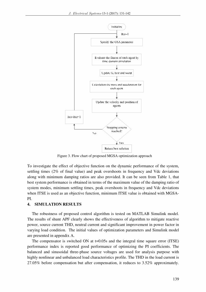
Figure 3. Flow chart of proposed MGSA optimization approach
To investigate the effect of objective function on the dynamic performance of the system,
settling times (2% of final value) and peak overshoots in frequency and Vdc deviations
along with minimum damping ratios are also provided. It can be seen from Table 1, that
best system performance is obtained in terms of the maximum value of the damping ratio of
system modes, minimum settling times, peak overshoots in frequency and Vdc deviations
when ITSE is used as an objective function, minimum ITSE value is obtained with MGSA-
PI.
4. SIMULATION RESULTS
The robustness of proposed control algorithm is tested on MATLAB Simulink model.
The results of shunt APF clearly shows the effectiveness of algorithm to mitigate reactive
power, source current THD, neutral current and significant improvement in power factor in
varying load condition. The initial values of optimization parameters and Simulink model
are presented in appendix A.
The compensator is switched ON at t=0.05s and the integral time square error (ITSE)
performance index is reported good performance of optimizing the PI coefficients. The
balanced and sinusoidal three-phase source voltages are used for analysis purpose with
highly nonlinear and unbalanced load characteristics profile. The THD in the load current is
27.05% before compensation but after compensation, it reduces to 3.52% approximately.
P. Anjana et al: Optimisation Based Shunt APF Controller to Mitigate Reactive Power...
140
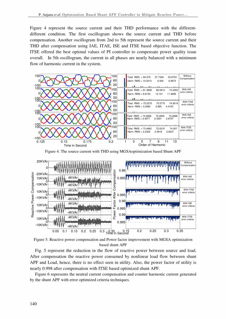
Figure 4 represent the source current and their THD performance with the different-
different condition. The first oscillogram shows the source current and THD before
compensation. Another oscillogram from 2nd to 5th represent the source current and their
THD after compensation using IAE, ITAE, ISE and ITSE based objective function. The
ITSE offered the best optimal values of PI controller to compensate power quality issue
overall. In 5th oscillogram, the current in all phases are nearly balanced with a minimum
flow of harmonic current in the system.
Figure 4. The source current with THD using MGSAoptimization based Shunt APF
Figure 5. Reactive power compensation and Power factor improvement with MGSA optimization
based shunt APF
Fig. 5 represent the reduction in the flow of reactive power between source and load.
After compensation the reactive power consumed by nonlinear load flow between shunt
APF and Load, hence, there is no effect seen in utility. Also, the power factor of utility is
nearly 0.998 after compensation with ITSE based optimized shunt APF.
Figure 6 represents the neutral current compensation and counter harmonic current generated
by the shunt APF with error optimized criteria techniques.
-100
0
100
-100
0
100
-100
0
100
0.125 0.15 0.175 0.2-100
0
100
Time in Second
-100
0
100
1 3 5 7 9 11 13
20
60
100Total RMS = 73.4662 73.0215 74.007
Harm. RMS = 2.2325 2.4818 2.8237
Order of Harmonic
20
60
100Total RMS = 72.6956 72.2605 73.2898Harm. RMS = 2.4577 2.4301 2.6707
20
60
100Total RMS = 75.5375 70.5775 74.9519
Harm. RMS = 3.2992 3.885 4.4103
20
60
100 Total RMS = 81.3828 69.5912 73.4353
Harm. RMS = 8.6152 12.101 11.4699
20
60
100 Total RMS = 84.579 57.7349 33.8704
Harm. RMS = 10.0013 6.934 6.9972
WithoutCompensation
With IAE error criteria
With ITAE error criteria
With ISE error criteria
With ITSE error criteria
-10KVAr0
10KVAr
-10KVAr0
10KVAr
Re
active
Po
we
r C
om
pe
nsa
tio
n
0.05 0.1 0.15 0.2 0.25 0.3 0.35
-10KVAr0
10KVAr
Time in Second
-10KVAr0
10KVAr
-20KVAr
0
20KVAr
0.99
0.995
0.86
0.15 0.2 0.25 0.3 0.35
0.995
0.995
0.99
0.995
Po
we
r F
acto
r A
fte
r C
om
pe
nsa
tio
n
-4KVAr
4KVAr
-4KVAr
4KVAr
-4KVAr
4KVAr
-4KVAr
4KVAr
WithoutCompensation
With IAE error criteria
With ITAE error criteria
With ISE error criteria
With ITSE error criteria

J. Electrical Systems 13-1 (2017): 131-142
141
Figure 6. Neutral Current compensation and Compensating current with GSA based control strategy
for Shunt APF.
Figure 7. DC link voltage with variable load condition.
As represented in Figure 7, the stable point of DC link voltage decreases slightly due to a
sudden connection/removal of the load. The ITSE objective function based PI controller
performance is superior to compensates the load disturbance and the Vdc voltage remains
equal to its reference Vdc. From the responses, it is depicted that the settling time required
by the PI controller is approximately 8 cycles whereas in the case of ITSE optimized
controller is about 6 cycles. The source current THD is reduced near to 4% in case of PI
controller and 2.62% in case of ITSE optimized controller, which is below IEEE standard
with both the controllers.
5. CONCLUSION
The optimization techniques are illustrated for tuning of PI controller in shunt APF. The
objective function of optimization is tested with IAE, ITAE, ISE and ITSE based GSA
optimization technique. Various simulation results are carried out to analyze the
performance of the proposed technique. The performance of ITSE based GSA-PI controller
is better than other error minimization technique. The heuristic modified GSA reported
robust performance to control the power quality problem using shunt APF. The THD of the
source current is below 5%, the harmonics limit imposed by IEEE standard.
References: [1] IEEE Working Group on Power System Harmonics, “Power system harmonics: An overview,” IEEE
Transaction on Power Application Syst., vol. PAS-102, pp. 2455–2460, 1983.
[2] J. S. Subjak and J. S. Mcquilkin, “Harmonics-causes, effects, measurements, analysis: An update,” IEEE
Transactions on Industry Applications, vol. 26, pp. 1034–1042, 1990.
-70Amp
0
70Amp
-70Amp
0
70Amp
Ne
utr
al C
urr
en
t A
fte
r C
om
pe
nsatio
n
0.05 0.1 0.15 0.2 0.25 0.3 0.35
-70Amp
0
70Amp
-70Amp
0
70Amp
-70Amp
0
70Amp
-50
0
50
-50
0
50
0.15 0.2 0.25 0.3 0.35
-500
50
-50
0
50
-6Amp
6Amp
-6Amp
6Amp
-6Amp
6Amp
-6Amp
6Amp
-50
0
50
Co
mp
en
sa
tio
n C
urr
ent
WithoutCompensation
With IAE error criteria
With ITAE error criteria
With ISE error criteria
With ITSE error criteria
0 0.05 0.1 0.15 0.2 0.25 0.3 0.35600
650
700
750
Time in Second
VDCRef
VDC
(IAE)
VDC
(ITAE)
VDC
(ITSE)
VDC
(ISE)

P. Anjana et al: Optimisation Based Shunt APF Controller to Mitigate Reactive Power...
142
[3] T. C. Shuter, H. T. Vollkommer and T.L. Kirkpatrick, “Survey of harmonic levels on the American electric
power distribution system,” IEEE Transaction On Power Delivery, vol. 4, no. 4, pp. 2204–2213, 1989.
[4] H. Akagi, “Trends in active power line conditioners,” IEEE Trans. Power Electronics, vol. 9, no. 3, pp. 263–
268, 1994.
[5] R.S. Herrera, P. Salmeron and H. Kim, “Instantaneous Reactive Power Theory Applied to Active Power
Filter Compensation: Different Approaches, Assessment and Experimental Results,” IEEE Transactions on Industrial Electronics, vol. 55, no. 1, pp. 184-196, 2008.
[6] A. Kumar, H. Tiwari and P. Anjana, “Review of Active Power Filters for Improvement of Power Quality,”
INROADS- An international Journal of Jaipur National University, vol. 5, no. 1s, pp. 135-144, 2016. [7] S. Orts-Grau, F. J. Gimeno-Sales, A. Abellán-García, S. Seguí-Chilet and J. C. Alfonso-Gil, “Improved
Shunt Active Power Compensator for IEEE Standard 1459 Compliance,” IEEE Transactions on Power
Delivery, vol. 25, no. 4, pp. 2692-2701, 2010. [8] R.S. Herrera and P Salmeron, “Instantaneous Reactive Power Theory: A Comparative Evaluation of
Different Formulations,” IEEE Transactions on Power Delivery, vol. 22, no. 1, pp. 595-604, 2007.
[9] J. G. Ziegler and N. B. Nichols, “Optimum Settings for Automatic Controllers,” Journal of Dynamic
Systems, Measurement, and Control, vol. 115, no. 2B, pp. 220-22, 1993.
[10] K. J. Astrom and T. Hagglund, “PID Controllers: Theory, design, and tuning, Research Triangle Park, N.C.
International Society for Measurement and Control, 1995. [11] K.J. Astrom and T. Hagglund, “Automatic tuning of simple regulators with specifications on phase and
amplitude margins,” Automatica, vol 20, no. 5, pp. 645-651, 1984.
[12] S. Skogestad and I. Postlethwaite, “Multivariable feedback control: analysis and design,” vol. 2. New York: Wiley, 2007.
[13] S. Dormido and F. Morilla, “Tuning of PID controllers based on sensitivity margin specification,”
in Proceedings of 5th Asian Control Conference, Melbourne, Australia, vol. 1, pp. 486-491, 2004.
[14] R. K. Sahu , S. Panda and S. Padhan, “A novel hybrid gravitational search and pattern search algorithm for
load frequency control of nonlinear power system,” Applied Soft Computing, vol. 29, pp. 310-327, 2015.
[15] U.K. Rout, R.K. Sahu and S. Panda, “Design and analysis of differential evolution algorithm based automatic generation control for interconnected power system,” Ain Shams Engineering Journal, vol. 4, no.
3, pp. 409-421, 2013.
[16] E. Rashedi, H. Nezamabadi-Pour and S. Saryazdi, “GSA: a gravitational search algorithm,” Information Sciences, vol. 179, no. 13, pp. no. 2232-2248, 2009.
[17] S. Panda, N.K. Yegireddy and S.K. Mahapatra, “Hybrid BFOA-PSO approach for coordi-nated design of
PSS and SSSC-based controller considering time delays,” International Journal of Electrical Power and
Energy Systems, vol. 49, pp. 221–233, 2013.
[18] L.B.G. Campanhol, S.A.O. da Silva and A. Goedtel, “Application of shunt active power filter for harmonic
reduction and reactive power compensation in three-phase four-wire systems.” IET Power Electronics, vol. 7, no. 11, pp. 2825-2836, 2014.
[19] L. Gyugi, and E.C. Strycula, “Active ac power filters”, IEEE IAS Annual Meeting, pp. 529–53, 1976
[20] W.H. Choi, C.S. Lam, M.C. Wong and Y.D. Han, “Analysis of DC-Link Voltage Controls in Three-Phase Four-Wire Hybrid Active Power Filters,” IEEE Transactions on Power Electronics, vol. 28, no. 5, pp. 2180-
2191, 2013.
[21] S.B. Karanki, N. Geddada, M. K. Mishra and B.K. Kumar, “A DSTATCOM Topology With Reduced DC-
Link Voltage Rating for Load Compensation With Nonstiff Source,” IEEE Transactions on Power
Electronics, vol. 27, no. 3, 2012.
[22] R.M. Ciric, A.P. Feltrin and L.F. Ochoa, “Power Flow in Four-Wire Distribution Networks-General Approach,” IEEE Transactions on Power Systems, vol. 18, no. 4, pp. 1283-1290, 2003.
[23] P. Kumar and A. Mahajan, “Soft computing techniques for the control of an active power filter,” IEEE
Transactions on Power Delivery, vol. 24, no. 1, pp. 452-461, 2009. Appendix A
Peak voltage and frequency V 328V,50 Hz
Supply /line inductance ,resistance 0.5mH,0.7 Ω
Coupling inductance 3.5mH
For VS Type Load resistance 26.66 Ω
For CS Type Load resistance, load inductance 26.66 Ω,10 mH
For CS Single phase b/w c and n 36.66 Ω,10mH
Single phase linear load b/w a and n 60 Ω,10mH
Inverter DC( bus voltage and capacitance 685 V, 2200µF
population size NP 30
maximum iteration T 500
gravitational constants G0 30
Weight Factor α = g 10