owners service manual installation, operating and ... · owners service manual installation,...
TRANSCRIPT
Manual 18764 Rev - Page 1
OWNERS SERVICE MANUAL
INSTALLATION, OPERATING AND SERVICING
Model SGMH 781K ABC (AMMONIUM PHOSPHATE BASE)
Model SGMH 783K PK (Potassium Bicarbonate)
RECHARGE FIRE EXTINGUISHERS IMMEDIATELY AFTER ANY USE
Manual 18764 Rev - Page 2
AMEREX CORPORATION DOES NOT SERVICE, MAINTAIN OR RECHARGE FIRE EXTINGUISHERS. THIS MANUAL IS PUBLISHED AS A GUIDE TO ASSIST
QUALIFIED SERVICE PERSONNEL IN THE INSPECTION, MAINTENANCE AND RECHARGE OF AMEREX FIRE EXTINGUISHERS ONLY. NO INSTRUCTION MANUAL CAN ANTICIPATE ALL POSSIBLE MALFUNCTIONS THAT MAY BE ENCOUNTERED IN THE SERVICE OF FIRE EXTINGUISHERS. DUE TO THE
POSSIBILITY THAT PRIOR SERVICE PERFORMED ON THIS EQUIPMENT MAY HAVE BEEN IMPROPERLY DONE, IT IS EXTREMELY IMPORTANT THAT ALL
WARNINGS, CAUTIONS AND NOTES IN THIS MANUAL BE CAREFULLY OBSERVED. FAILURE TO HEED THESE INSTRUCTIONS COULD RESULT IN
SERIOUS INJURY. AMEREX ASSUMES NO LIABILITY FOR SERVICE, MAINTENANCE OR RECHARGE OF FIRE EXTINGUISHERS BY PUBLISHING THIS
MANUAL.
PREPARING YOUR NEW EXTINGUISHER FOR USE
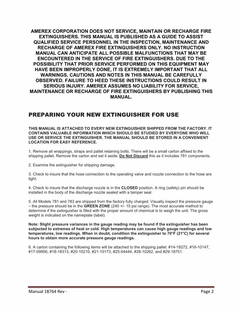
THIS MANUAL IS ATTACHED TO EVERY NEW EXTINGUISHER SHIPPED FROM THE FACTORY. IT CONTAINS VALUABLE INFORMATION WHICH SHOULD BE STUDIED BY EVERYONE WHO WILL USE OR SERVICE THE EXTINGUISHER. THE MANUAL SHOULD BE STORED IN A CONVENIENT LOCATION FOR EASY REFERENCE. 1. Remove all wrappings, straps and pallet retaining bolts. There will be a small carton affixed to the shipping pallet. Remove the carton and set it aside. Do Not Discard this as it includes 781 components. 2. Examine the extinguisher for shipping damage. 3. Check to insure that the hose connection to the operating valve and nozzle connection to the hose are tight. 4. Check to insure that the discharge nozzle is in the CLOSED position. A ring (safety) pin should be installed in the body of the discharge nozzle sealed with a tamper seal. 5. All Models 781 and 783 are shipped from the factory fully charged. Visually inspect the pressure gauge – the pressure should be in the GREEN ZONE (240 +/- 15 psi range). The most accurate method to determine if the extinguisher is filled with the proper amount of chemical is to weigh the unit. The gross weight is indicated on the nameplate (label). Note: Slight pressure variances in the gauge reading may be found if the extinguisher has been subjected to extremes of heat or cold. High temperatures can cause high gauge readings and low temperatures, low readings. When in doubt, condition the extinguisher to 70°F (21°C) for several hours to obtain more accurate pressure gauge readings. 6. A carton containing the following items will be attached to the shipping pallet: #14-19272, #16-10147, #17-09956, #18-18313, #20-10210, #21-10173, #25-04444, #28-10262, and #29-18751.
Manual 18764 Rev - Page 3
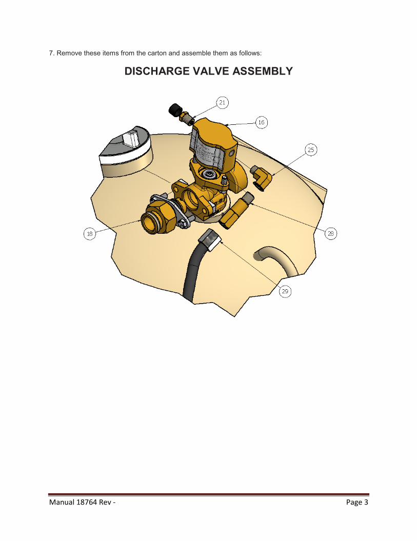
7. Remove these items from the carton and assemble them as follows:
DISCHARGE VALVE ASSEMBLY
Manual 18764 Rev - Page 4
ACTUATION CYLINDER ASSEMBLY
8. Record the date the unit is being placed into service on the inspection tag and attach it to the extinguisher.
DO NOT FUNCTIONALLY TEST THIS FIRE EXTINGUISHER. Testing or any use may cause the extinguisher to gradually lose pressure and become ineffective.
Manual 18764 Rev - Page 5
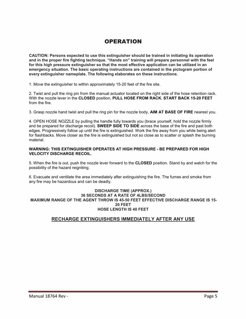
OPERATION
CAUTION: Persons expected to use this extinguisher should be trained in initiating its operation and in the proper fire fighting technique. “Hands on” training will prepare personnel with the feel for this high pressure extinguisher so that the most effective application can be utilized in an emergency situation. The basic operating instructions are contained in the pictogram portion of every extinguisher nameplate. The following elaborates on these instructions.
1. Move the extinguisher to within approximately 15-20 feet of the fire site. 2. Twist and pull the ring pin from the manual actuator located on the right side of the hose retention rack. With the nozzle lever in the CLOSED position, PULL HOSE FROM RACK. START BACK 15-20 FEET from the fire. 3. Grasp nozzle hand twist and pull the ring pin for the nozzle body, AIM AT BASE OF FIRE nearest you. 4. OPEN HOSE NOZZLE by pulling the handle fully towards you (brace yourself, hold the nozzle firmly and be prepared for discharge recoil). SWEEP SIDE TO SIDE across the base of the fire and past both edges. Progressively follow up until the fire is extinguished. Work the fire away from you while being alert for flashbacks. Move closer as the fire is extinguished but not so close as to scatter or splash the burning material. WARNING: THIS EXTINGUISHER OPERATES AT HIGH PRESSURE - BE PREPARED FOR HIGH VELOCITY DISCHARGE RECOIL. 5. When the fire is out, push the nozzle lever forward to the CLOSED position. Stand by and watch for the possibility of the hazard reigniting. 6. Evacuate and ventilate the area immediately after extinguishing the fire. The fumes and smoke from any fire may be hazardous and can be deadly.
DISCHARGE TIME (APPROX.)
36 SECONDS AT A RATE OF 4LBS/SECOND MAXIMUM RANGE OF THE AGENT THROW IS 45-50 FEET EFFECTIVE DISCHARGE RANGE IS 15-
20 FEET HOSE LENGTH IS 40 FEET
RECHARGE EXTINGUISHERS IMMEDIATELY AFTER ANY USE
Manual 18764 Rev - Page 6
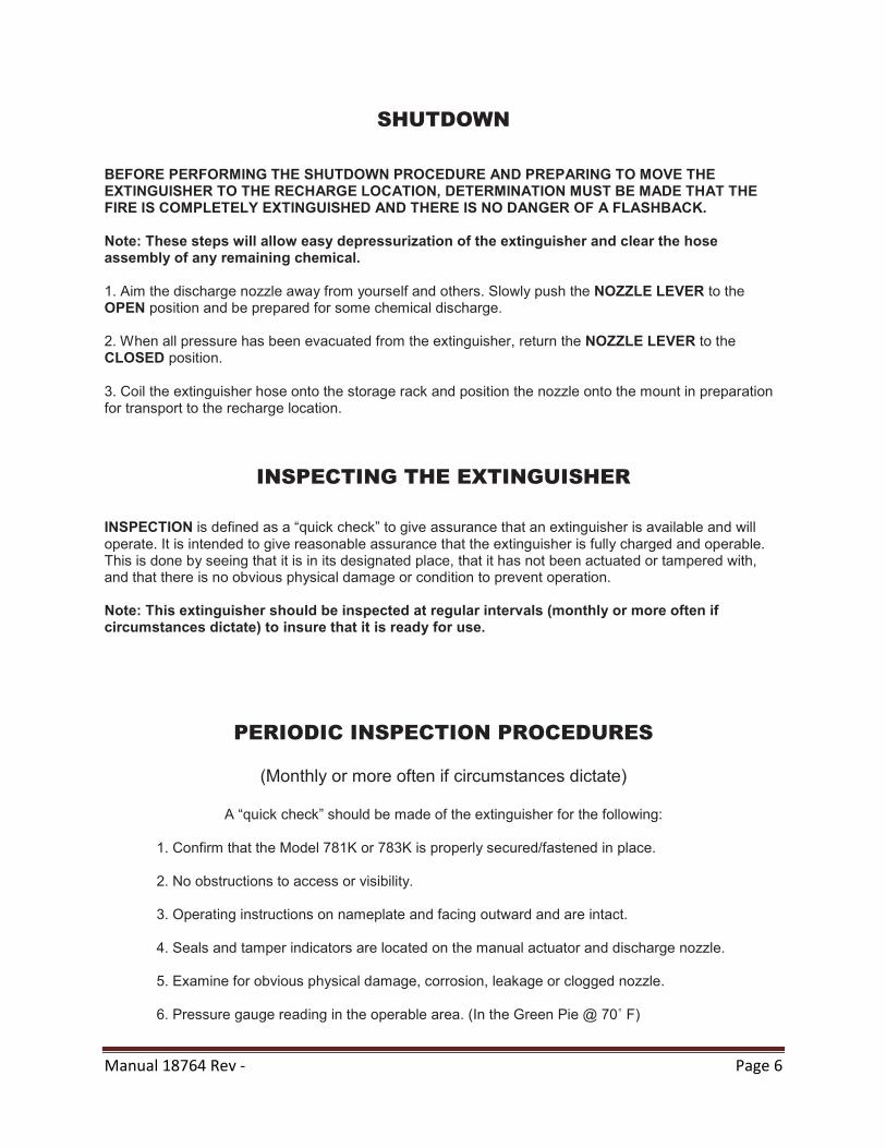
SHUTDOWN BEFORE PERFORMING THE SHUTDOWN PROCEDURE AND PREPARING TO MOVE THE EXTINGUISHER TO THE RECHARGE LOCATION, DETERMINATION MUST BE MADE THAT THE FIRE IS COMPLETELY EXTINGUISHED AND THERE IS NO DANGER OF A FLASHBACK. Note: These steps will allow easy depressurization of the extinguisher and clear the hose assembly of any remaining chemical. 1. Aim the discharge nozzle away from yourself and others. Slowly push the NOZZLE LEVER to the OPEN position and be prepared for some chemical discharge. 2. When all pressure has been evacuated from the extinguisher, return the NOZZLE LEVER to the CLOSED position. 3. Coil the extinguisher hose onto the storage rack and position the nozzle onto the mount in preparation for transport to the recharge location.
INSPECTING THE EXTINGUISHER
INSPECTION is defined as a “quick check” to give assurance that an extinguisher is available and will operate. It is intended to give reasonable assurance that the extinguisher is fully charged and operable. This is done by seeing that it is in its designated place, that it has not been actuated or tampered with, and that there is no obvious physical damage or condition to prevent operation. Note: This extinguisher should be inspected at regular intervals (monthly or more often if circumstances dictate) to insure that it is ready for use.
PERIODIC INSPECTION PROCEDURES
(Monthly or more often if circumstances dictate)
A “quick check” should be made of the extinguisher for the following:
1. Confirm that the Model 781K or 783K is properly secured/fastened in place. 2. No obstructions to access or visibility. 3. Operating instructions on nameplate and facing outward and are intact. 4. Seals and tamper indicators are located on the manual actuator and discharge nozzle. 5. Examine for obvious physical damage, corrosion, leakage or clogged nozzle. 6. Pressure gauge reading in the operable area. (In the Green Pie @ 70˚ F)
Manual 18764 Rev - Page 7
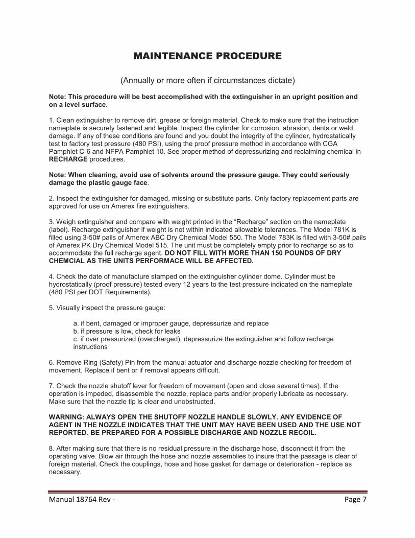
MAINTENANCE PROCEDURE
(Annually or more often if circumstances dictate)
Note: This procedure will be best accomplished with the extinguisher in an upright position and on a level surface. 1. Clean extinguisher to remove dirt, grease or foreign material. Check to make sure that the instruction nameplate is securely fastened and legible. Inspect the cylinder for corrosion, abrasion, dents or weld damage. If any of these conditions are found and you doubt the integrity of the cylinder, hydrostatically test to factory test pressure (480 PSI), using the proof pressure method in accordance with CGA Pamphlet C-6 and NFPA Pamphlet 10. See proper method of depressurizing and reclaiming chemical in RECHARGE procedures. Note: When cleaning, avoid use of solvents around the pressure gauge. They could seriously damage the plastic gauge face. 2. Inspect the extinguisher for damaged, missing or substitute parts. Only factory replacement parts are approved for use on Amerex fire extinguishers. 3. Weigh extinguisher and compare with weight printed in the “Recharge” section on the nameplate (label). Recharge extinguisher if weight is not within indicated allowable tolerances. The Model 781K is filled using 3-50# pails of Amerex ABC Dry Chemical Model 550. The Model 783K is filled with 3-50# pails of Amerex PK Dry Chemical Model 515. The unit must be completely empty prior to recharge so as to accommodate the full recharge agent. DO NOT FILL WITH MORE THAN 150 POUNDS OF DRY CHEMCIAL AS THE UNITS PERFORMACE WILL BE AFFECTED. 4. Check the date of manufacture stamped on the extinguisher cylinder dome. Cylinder must be hydrostatically (proof pressure) tested every 12 years to the test pressure indicated on the nameplate (480 PSI per DOT Requirements). 5. Visually inspect the pressure gauge:
a. if bent, damaged or improper gauge, depressurize and replace b. if pressure is low, check for leaks c. if over pressurized (overcharged), depressurize the extinguisher and follow recharge instructions
6. Remove Ring (Safety) Pin from the manual actuator and discharge nozzle checking for freedom of movement. Replace if bent or if removal appears difficult. 7. Check the nozzle shutoff lever for freedom of movement (open and close several times). If the operation is impeded, disassemble the nozzle, replace parts and/or properly lubricate as necessary. Make sure that the nozzle tip is clear and unobstructed. WARNING: ALWAYS OPEN THE SHUTOFF NOZZLE HANDLE SLOWLY. ANY EVIDENCE OF AGENT IN THE NOZZLE INDICATES THAT THE UNIT MAY HAVE BEEN USED AND THE USE NOT REPORTED. BE PREPARED FOR A POSSIBLE DISCHARGE AND NOZZLE RECOIL. 8. After making sure that there is no residual pressure in the discharge hose, disconnect it from the operating valve. Blow air through the hose and nozzle assemblies to insure that the passage is clear of foreign material. Check the couplings, hose and hose gasket for damage or deterioration - replace as necessary.
Manual 18764 Rev - Page 8
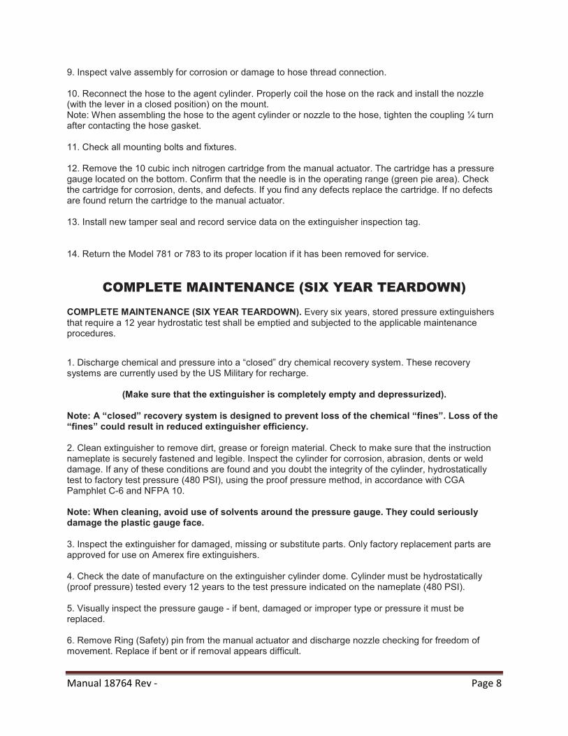
9. Inspect valve assembly for corrosion or damage to hose thread connection. 10. Reconnect the hose to the agent cylinder. Properly coil the hose on the rack and install the nozzle (with the lever in a closed position) on the mount. Note: When assembling the hose to the agent cylinder or nozzle to the hose, tighten the coupling ¼ turn after contacting the hose gasket. 11. Check all mounting bolts and fixtures. 12. Remove the 10 cubic inch nitrogen cartridge from the manual actuator. The cartridge has a pressure gauge located on the bottom. Confirm that the needle is in the operating range (green pie area). Check the cartridge for corrosion, dents, and defects. If you find any defects replace the cartridge. If no defects are found return the cartridge to the manual actuator. 13. Install new tamper seal and record service data on the extinguisher inspection tag. 14. Return the Model 781 or 783 to its proper location if it has been removed for service.
COMPLETE MAINTENANCE (SIX YEAR TEARDOWN) COMPLETE MAINTENANCE (SIX YEAR TEARDOWN). Every six years, stored pressure extinguishers that require a 12 year hydrostatic test shall be emptied and subjected to the applicable maintenance procedures.
1. Discharge chemical and pressure into a “closed” dry chemical recovery system. These recovery systems are currently used by the US Military for recharge.
(Make sure that the extinguisher is completely empty and depressurized). Note: A “closed” recovery system is designed to prevent loss of the chemical “fines”. Loss of the “fines” could result in reduced extinguisher efficiency. 2. Clean extinguisher to remove dirt, grease or foreign material. Check to make sure that the instruction nameplate is securely fastened and legible. Inspect the cylinder for corrosion, abrasion, dents or weld damage. If any of these conditions are found and you doubt the integrity of the cylinder, hydrostatically test to factory test pressure (480 PSI), using the proof pressure method, in accordance with CGA Pamphlet C-6 and NFPA 10. Note: When cleaning, avoid use of solvents around the pressure gauge. They could seriously damage the plastic gauge face. 3. Inspect the extinguisher for damaged, missing or substitute parts. Only factory replacement parts are approved for use on Amerex fire extinguishers. 4. Check the date of manufacture on the extinguisher cylinder dome. Cylinder must be hydrostatically (proof pressure) tested every 12 years to the test pressure indicated on the nameplate (480 PSI). 5. Visually inspect the pressure gauge - if bent, damaged or improper type or pressure it must be replaced. 6. Remove Ring (Safety) pin from the manual actuator and discharge nozzle checking for freedom of movement. Replace if bent or if removal appears difficult.
Manual 18764 Rev - Page 9
7. VERIFY THAT NO PRESSURE REMAINS IN THE EXTINGUISHER (Operating valve and nozzle shutoff in open position and there is no discharge). Remove and inspect the agent fill cap for damage or distortion. 8. Check the nozzle shutoff lever for freedom of movement (open and close several times). If the operation is impeded, disassemble the nozzle, replace parts and/or properly lubricate as necessary. Make sure that the nozzle tip is clear and unobstructed. 9. Disconnect the discharge hose from the operating valve. Blow air through the hose and nozzle assemblies to insure that the passage is clear of foreign material. Check the couplings, hose and hose gasket for damage or deterioration - replace as necessary. 10. Check cylinder mounting assembly for loose nuts, bolts, frame distortion or damage. Check welds for damage or corrosion. Replace damaged parts or make repairs as necessary. 11. Remove operating valve assembly. Inspect for corrosion or damage to hose thread connection. Visually inspect the safety disc assembly on the discharge valve for obstruction or damage. WARNING: VALVE REMOVAL AND/OR VALVE PART REPLACEMENT SHOULD BE MADE ONLY AFTER COMPLETING THE DEPRESSURIZING PROCEDURES LISTED IN STEP 1 OF THE COMPLETE MAINTENANCE PROCEDURES. 13. Complete steps 2 thru 15 of RECHARGE PROCEDURE.
RECHARGE
RECHARGING is the replacement of the extinguishing agent and also includes the expellant gas for this type of extinguisher. WARNINGS: A. BE SURE THE EXTINGUISHER IS COMPLETELY DEPRESSURIZED BEFORE ATTEMPTING TO RECHARGE. B. NEVER HAVE ANY PART OF YOUR BODY OVER THE EXTINGUISHER WHILE REMOVING THE VALVE ASSEMBLY OR FILL CAP. C. USE A PROTECTIVE SHIELD BETWEEN YOU AND THE PRESSURE GAUGE WHILE CHARGING AN EXTINGUISHER. DO NOT STAND IN FRONT OF THE GAUGE IF A SHIELD IS NOT AVAILABLE. D. USE A REGULATED PRESSURIZING SOURCE OF DRY NITROGEN ONLY WITH A MINIMUM DEW POINT OF MINUS 70°F (MINUS 57°C). SET THE REGULATOR TO NO MORE THAN 275 PSI. E. CHECK AND CALIBRATE REGULATOR GAUGE AT FREQUENT INTERVALS. THE REGULATOR GAUGE SHOULD BE USED TO DETERMINE WHEN THE INTENDED CHARGING PRESSURE HAS BEEN REACHED. DO NOT USE THE EXTINGUISHER GAUGE FOR THIS PURPOSE.
Manual 18764 Rev - Page 10
F. NEVER LEAVE AN EXTINGUISHER CONNECTED TO A REGULATOR OF A HIGH PRESSURE SOURCE FOR AN EXTENDED PERIOD OF TIME. A DEFECTIVE REGULATOR COULD CAUSE THE CYLINDER TO RUPTURE DUE TO EXCESSIVE PRESSURE. G. DO NOT MIX TYPES OF DRY CHEMICALS IN EXTINGUISHERS, RECHARGE OR RECOVERY SYSTEMS. MIXING ABC (ACIDIC BASE) WITH REGULAR, PURPLE-K, SUPER-K OR MONNEX (ALKALINE BASE) DRY CHEMICALS MAY RESULT IN A CHEMICAL REACTION CAPABLE OF DEVELOPING A DANGEROUS PRESSURE BUILDUP.
RECHARGING PROCEDURE
1. Perform steps 1 thru 12 of the “COMPLETE MAINTENANCE (SIX YEAR TEARDOWN)” section. 2. Remove down tube, spring and valve stem assembly from the operating valve and thoroughly clean all parts with a soft bristle brush or soft cloth. Blow the valve and down tube out with air or nitrogen. Inspect the collar o-ring, valve stem, spring and down tube assembly - replace parts if worn or damaged. Lubricate the collar o-ring and small o-ring on the valve stem with Visilox V-711 (DO NOT LUBRICATE THE VALVE STEM SEAL). Visilox V-711 is provided as part of the Model 781K Recharge station assembly. 3. Reassemble the valve assembly, including down tube and set aside. 4. Remove agent fill cap and place to the side. Remove any chemical remaining in the cylinder and check the condition. Properly dispose of any chemical that is contaminated or caked. 5. Inspect the interior of the cylinder following CGA Visual Inspection Standard, Pamphlet C-6. 6. Clean cylinder collar o-ring seat and collar threads with a small brush and then wipe off surfaces with a clean damp cloth to remove dust. Lightly brush the collar o-ring seat with Visilox V-711. Install operating valve/down tube assembly HAND TIGHT. 7. Stand the extinguisher upright on an accurate scale of sufficient size and capacity. Use the Amerex Fill Station Assembly to accomplish this process. Fill cylinder through chemical agent fill opening with the correct amount and type of dry chemical specified on the label (nameplate). Use AMEREX chemical (Included with the Model 781K or 783K Recharge Kit) which has been kept free of moisture and contamination. WARNING: FILLING BY EYE ALONE COULD CAUSE POTENTIALLY DANGEROUS OVER-FILLING - ALWAYS USE A SCALE. 8. Remove agent fill cap 0-ring. Clean cap and cylinder threads with a small brush and wipe surfaces with a clean damp cloth to remove dust. Inspect o-ring and replace if damaged or deformed. Install o-ring and lightly brush it and all threads with Visilox V-711. Install agent fill cap HAND TIGHT. 9. Attach the nitrogen charging adapter to the male hose connector on the operating valve. 10. With the extinguisher properly secured in an upright position, connect your nitrogen pressurizing line with a quick connect to the nitrogen charging adapter. Rotate the operating Tee Handle Pressurizing Adaptor valve lever to the OPEN position and pressurize extinguisher with dry nitrogen to 240 psi. When the desired pressure has been reached, rotate the operating lever to the CLOSED position. Shut off nitrogen supply and remove the quick connect.
Manual 18764 Rev - Page 11
11. Remove the nitrogen charging adapter. Check extinguisher for leaks by applying leak detecting fluid or a solution of soapy water to the male hose connector orifice, around the collar o-ring sealing areas of valve and fill cap, cylinder welds and gauge. Remove leak detecting fluid from valve assembly by blowing out with air or nitrogen. Wipe exterior of extinguisher to remove any remaining residue. 12. Reconnect the hose to the operating valve. Properly coil the hose on the rack and install the nozzle (with the lever in a closed position) on the mount. CAUTION: WHEN ASSEMBLING THE HOSE TO THE AGENT CYLINDER OR NOZZLE TO THE HOSE, TIGHTEN THE COUPLING ¼ TURN AFTER CONTACTING THE HOSE GASKET. 13. Install the Ring (Safety) pin and lock wire (tamper) seal in the manual actuator. Record recharge date and attach new recharge tag. 14. Weigh assembled extinguisher and confirm that the total weight is within the allowable tolerances indicated in the “Maintenance” section of the nameplate (label). 15. Return the extinguisher to its proper location. 14. Weigh assembled extinguisher and confirm that the total weight is within the allowable tolerances indicated in the “Maintenance” section of the nameplate (label). 15. Return the extinguisher to its proper location.

Manual 18764 Rev - Page 12
The following installation instructions should be followed to avoid hose twisting and kinking as
the hose is coiled on the retention rack.
Lay the hose straight on the ground The second loop is a “reverse” to its full 40’ length. Start the first loop loop. Note that the hose passes counter-clockwise by placing it over the behind the loop on this coil. retention bracket as shown.
The next loop is a regular “hose in front” Adjust loops so that the nozzle fits loop. Succeeding loops are alternated, into the nozzle mount. Loops should reverse, front, etc. until the hose is installed. be approximately the same length.
Manual 18764 Rev - Page 13
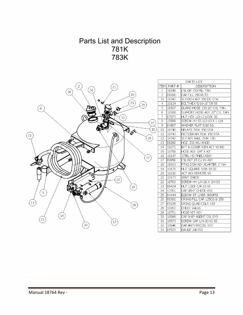
Parts List and Description 781K 783K