owners & installation p36 gas log fireplace
TRANSCRIPT

Models: P36-NG5 P36-LPG5
Owners &Installation
PLEASE KEEP THESE INSTRUCTIONS FOR FUTURE REFERENCE
Man
ual
12/24/13
LISTINGS AND CODE APPROVALS
These gas appliances have been tested in accordance with AS4553-2000, NZS 5262 and have been certifi ed by the Australian Gas Association for installation and operation as described in these Installation and Operating Instructions.
Your unit should be serviced annually by an authorised service person.
918-538d
WARNING: Improper installation, adjustment, alteration, service or maintenance can cause injury or property damage. Refer to this manual. For assistance or additional information consult an authorised installer, service agency or the gas supplier.
FOR YOUR SAFETYDo not store or use gasoline or other fl ammable vapours and liquids in the vicinity of this or any other appliance.Installation and service must be performed by an authorised installer, service agency or the gas supplier.
P36 GAS LOG FIREPLACE
FOR YOUR SAFETYWhat to do if you smell gas: Do not try to light any
appliance Do not touch any electrical
switch: do not use any phone in your building.
Immediately call your gas supplier from a neighbour's phone. Follow the gas supplier's instructions.
If you cannot reach your gas supplier, call the fi re department.

Regency® P36-5 Gas Log Fireplace2
TO THE NEW OWNER:
Congratulations! You are the owner of a state-of-the-art Gas Log Fireplace by FPI FIREPLACE PRODUCTS INTERNATIONAL. The P36 has been designed to provide you with all the warmth and charm of a wood fi replace at the fl ick of a switch. The model P36 has been approved by the Australian Gas Association for both safety and effi ciency. As it also bears our own mark, it promises to provide you with economy, comfort and security for many trouble free years to follow. Please take a moment now to acquaint yourself with these instructions and the many features of your Regency® Fireplace.

Regency® P36-5 Gas Log Fireplace 3
TABLE OF CONTENTS
OPERATING INSTRUCTIONS
Fan ..............................................................................26Fan Removal ...............................................................26Lighting Procedure ......................................................28Normal Operating Sounds Of Gas Appliances ............28Shutdown Procedure ...................................................28First Fire ......................................................................28Copy Of The Lighting Plate Instructions ......................29Maintenance Instructions.............................................29Gold-plated & Brass ....................................................30Louvres OR Trim .........................................................30Log Replacement ........................................................30Thermopile / Thermocouple .........................................30Glass Gasket ...............................................................30Door Glass...................................................................30
MAINTENANCE
Removing Valve ...........................................................31Installing Valve .............................................................31
PARTS LIST
Main Assembly ............................................................32Burner Assembly & Log Set.........................................33Flush Front Accessories ..............................................34Premium Flush Front Assembly...................................35
WARRANTY
Warranty ......................................................................39
DATA BADGE
Data Badge....................................................................4
INSTALLATION
Important Message ........................................................5Before You Start ............................................................5General Safety Information............................................5Installation Checklist ......................................................5Clearances ....................................................................6Locating Your Gas fi replace...........................................6Manufactured Mobile Home Additional Requirements ..6Combustible Mantels .....................................................7Mantel Leg Clearances..................................................8Framing And Finishing ...................................................8Unit Assembly Prior To Installation ................................9Flueing Introduction .......................................................9Exterior Flue Termination Locations ............................10Flueing ......................................................................... 11Simpson Dura-vent Flueing .........................................12Simpson Dura-vent Flueing Components List .............12Flueing Arrangements - Horizontal Terminations .........13Flueing Arrangements - Horizontal Terminations .........14Flueing Arrangements - Vertical Terminations .............15Horizontal terminations ...............................................17Vertical Terminations ...................................................18Gas Line Installation ....................................................20Pilot Adjustment ...........................................................20Aeration Adjustment ....................................................20Gas Pipe Pressure Testing ..........................................20Optional Brick Panels ..................................................21Log Set Installation ......................................................21Standard Flush Door ...................................................23Option 1: Wall Switch ..................................................24Option 2: Remote Control ............................................24Option 3: Wall Thermostat ..........................................24Thermostat Wire Table ................................................24

Regency® P36-5 Gas Log Fireplace4
DATA BADGE
This is a copy of the label that accompanies each P36 Zero Clearance Room Sealed Gas Fireplace. We have printed a copy of the contents here for your review.
DO NO T
DO NO TDO NO T
DO NO T
DO NO TDO NO T
OPERATE THIS APPLIANCE BEFORE READING THEINSTRUCTIONS BOOKLET.PLACE ARTICLES ON OR AGAINST THIS APPLIANCESTORE CHEMICALS OR FLAMMABLE MATERIALS
SPRAY AEROSOLS IN THE VICINITY OF THISAPPLIANCE WHILE IN OPERATION.OPERATE WITH PANELS, COVERS OR GUARDSREMOVED FROM THIS APPLIANCE.ENCLOSE THIS APPLIANCE.MODIFY THIS APPLIANCE.
NEAR THIS APPLIANCE.DO NO T
908-602a
(Australia Only)
The label is located on the front inside base of the unit, visible when the bottom louvre is open.
DATA BADGE NOTE: Regency® units are constantly being improved. Check the label on the unit and if there is a difference, the label on the unit is the correct one.

Regency® P36-5 Gas Log Fireplace 5
INSTALLATION CHECKLIST
1) Locate appliance a) Locate Your Gas Fireplace b) Clearances c) Combustible Mantels d) Framing & Finishing
2) Assemble Top Standoffs and Top Facing Support and Side Nailing Strips, refer to section "Unit Assembly Prior to Installation". (NOTE: must be done before installing unit into fi replace.)
3) Install fl ue (Refer to section "Simpson Dura-vent Flueing").
4) Make gas and electrical connections. Test the pilot. Must be as per diagram. Refer to section "Pilot Adjustment."
5) Install standard and optional features. Refer to the following sections:
a. Brick Panels b. Log Set c. Flush Door d. Premium Flush Front e. Wall Switch f. Remote Control g. Wall Thermostat
6) Final check.
Before leaving this unit with the customer, the installer must ensure that the appliance is fi ring correctly and operation fully explained to customer.
This includes:
1) Clocking the appliance to ensure the correct fi ring rate (rate noted on label ) after burning appliance for 15 minutes.
2) If required, adjusting the primary air to ensure that the fl ame does not carbon. First allow the unit to burn for 15-20 min. to stabilize.
CAUTION: Any alteration to the product that causes sooting or carboning that results in damage is not the responsibility of the manufacturer.
INSTALLATION
IMPORTANT MESSAGESAVE THESE INSTRUCTIONS
The P36-NG or P36-LPG Room Sealed Fireplace must be installed in accordance with AS5601-2004 and NZS 5261 5261 and these instructions. Carefully read all the instructions in this manual fi rst. Consult the "authority having jurisdiction" to determine the need for a permit prior to starting the installation. It is the responsibility of the installer to ensure this fi replace is installed in compliance with manufacturer's instructions and all applicable codes.
BEFORE YOU STARTNOTE: NOT INTENDED AS A FIREPLACE INSERT.
GENERAL SAFETY INFORMATION
1) The appliance shall be installed in accordance with the manufacturer's installation instructions,local gas fi tting regulations, municipal building codes, water supply regulations, electrical wiring regulations, with AS5601-2004 (AGA gas installation code) NZS 5261 (New Zealand)
2) Installation and repair should be done ONLY by an authorised person.
3) THIS APPLIANCE IS NOT INTENDED AS A FIREPLACE INSERT. DO NOT CONNECT TO MASONARY FLUE.
4) This appliance must be connected to the specifi ed fl ue and termination cap to the outside of the building envelope. Never fl ue to another room or inside a building. Make sure that the fl ue is fi tted as per Flueing instructions.
5) Inspect the fl ueing system annually for blockage and any signs of deterioration.
6) Flueing terminals shall not be recessed into a wall or siding.
7) Any safety glass removed for servicing must be replaced prior to operating the appliance.
8) To prevent injury, do not allow anyone who is unfamiliar with the operation to use the fi replace.
9) Wear gloves and safety glasses for protection while doing required maintenance.
10) Be aware of electrical wiring locations in walls and ceilings when cutting holes for termination.
11) Under no circumstances should this appliance be modifi ed. Parts that have to be removed for servicing should be replaced prior to operating this appliance.
12) Installation and any repairs to this appliance should be done by an authorised service person. An authorised service person should be called to inspect this appliance annually. Make it a practice to have all of your gas appliances checked annually.
13) Do not slam shut or strike the glass door.
14) Under no circumstances should any solid fuels (wood, paper, cardboard, coal, etc.) be used in this appliance.
15) The appliance area must be kept clear and free of combustible materials, (gases and other fl ammable vapours and liquids).
INSTALLATION AND REPAIR SHOULD BE DONE BY A AUTHORISED SERVICE PERSON. THE APPLIANCE SHOULD BE INSPECTED BEFORE USE AND AT LEAST ANNUALLY BY AN AUTHORISED SERVICE PERSON. MORE FREQUENT CLEANING MAY BE REQUIRED DUE TO EXCESSIVE LINT FROM CARPETING, BEDDING MATERIAL, ETC. IT IS IMPERATIVE THAT CONTROL COMPARTMENTS, BURNERS AND CIRCULATING AIR PASSAGEWAYS OF THE APPLIANCE BE KEPT CLEAN.
DUE TO HIGH TEMPERATURES, THE APPLIANCE SHOULD BE LOCATED OUT OF TRAFFIC AND AWAY FROM FURNITURE AND DRAPERIES.
WARNING: FAILURE TO INSTALL THIS APPLIANCE CORRECTLY WILL VOID YOUR WARRANTY AND MAY CAUSE A SERIOUS HOUSE FIRE.
CHILDREN AND ADULTS SHOULD BE ALERTED TO THE HAZARDS OF HIGH SURFACE TEMPERATURES, ESPECIALLY THE FIREPLACE GLASS, AND SHOULD STAY AWAY TO AVOID BURNS OR CLOTHING IGNITION.
YOUNG CHILDREN SHOULD BE CAREFULLY SUPERVISED WHEN THEY ARE IN THE SAME ROOM AS THE APPLIANCE.
CLOTHING OR OTHER FLAMMABLE MATERIAL SHOULD NOT BE PLACED ON OR NEAR THE APPLIANCE. DO NOT USE AEROSOLS IN THE VICINITY OF THIS APPLIANCE.
Regency® P36-5 Gas Log Fireplace6
INSTALLATION
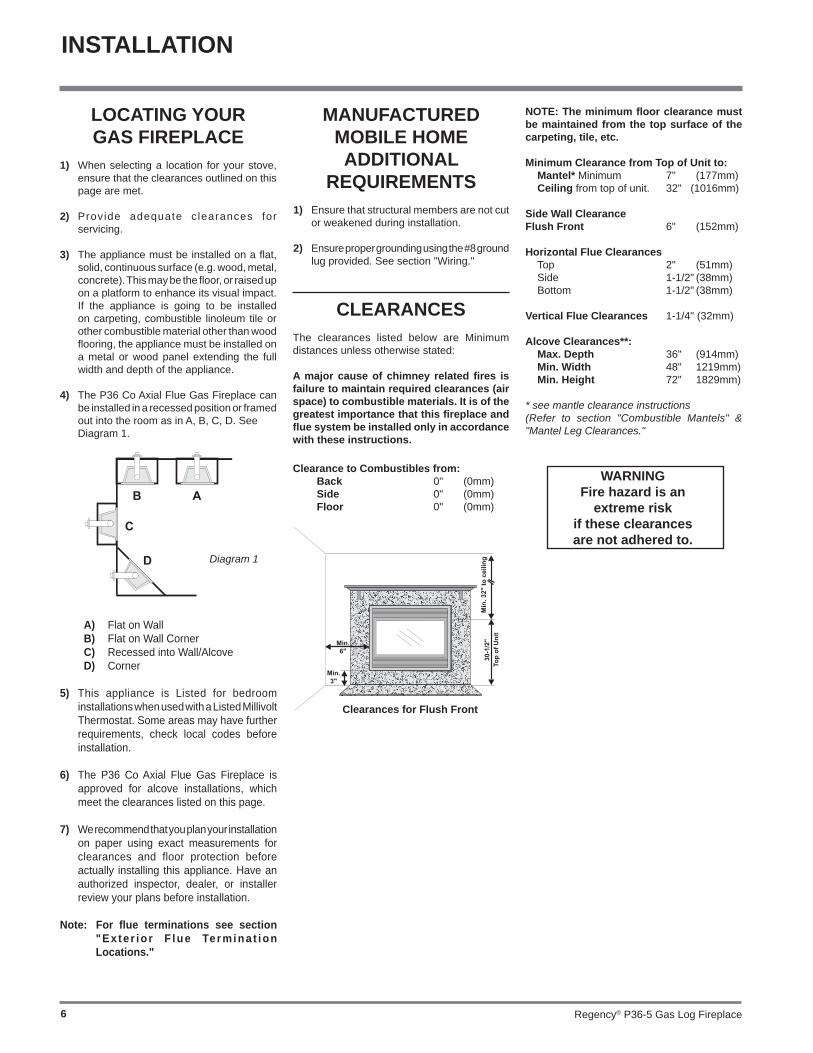
Clearances for Flush Front
NOTE: The minimum fl oor clearance must be maintained from the top surface of the carpeting, tile, etc.
Minimum Clearance from Top of Unit to: Mantel* Minimum 7" (177mm) Ceiling from top of unit. 32" (1016mm)
Side Wall ClearanceFlush Front 6" (152mm) Horizontal Flue Clearances Top 2" (51mm) Side 1-1/2" (38mm) Bottom 1-1/2" (38mm)
Vertical Flue Clearances 1-1/4" (32mm)
Alcove Clearances**: Max. Depth 36" (914mm) Min. Width 48" 1219mm) Min. Height 72" 1829mm)
* see mantle clearance instructions (Refer to section "Combustible Mantels" & "Mantel Leg Clearances."
CLEARANCESThe clearances listed below are Minimum distances unless otherwise stated:
A major cause of chimney related fi res is failure to maintain required clearances (air space) to combustible materials. It is of the greatest importance that this fi replace and fl ue system be installed only in accordance with these instructions.
Clearance to Combustibles from: Back 0" (0mm) Side 0" (0mm) Floor 0" (0mm)
Diagram 1
LOCATING YOUR GAS FIREPLACE
1) When selecting a location for your stove, ensure that the clearances outlined on this page are met.
2) Provide adequate c learances for servicing.
3) The appliance must be installed on a fl at, solid, continuous surface (e.g. wood, metal, concrete). This may be the fl oor, or raised up on a platform to enhance its visual impact. If the appliance is going to be installed on carpeting, combustible linoleum tile or other combustible material other than wood fl ooring, the appliance must be installed on a metal or wood panel extending the full width and depth of the appliance.
4) The P36 Co Axial Flue Gas Fireplace can be installed in a recessed position or framed out into the room as in A, B, C, D. See
Diagram 1.
MANUFACTURED MOBILE HOME ADDITIONAL
REQUIREMENTS1) Ensure that structural members are not cut
or weakened during installation.
2) Ensure proper grounding using the #8 ground lug provided. See section "Wiring."
A) Flat on WallB) Flat on Wall CornerC) Recessed into Wall/AlcoveD) Corner
5) This appliance is Listed for bedroom installations when used with a Listed Millivolt Thermostat. Some areas may have further requirements, check local codes before installation.
6) The P36 Co Axial Flue Gas Fireplace is approved for alcove installations, which meet the clearances listed on this page.
7) We recommend that you plan your installation on paper using exact measurements for clearances and floor protection before actually installing this appliance. Have an authorized inspector, dealer, or installer review your plans before installation.
Note: For fl ue terminations see section "Ex te r io r F lue Termina t ion Locations."
WARNINGFire hazard is an
extreme risk if these clearances are not adhered to.

Regency® P36-5 Gas Log Fireplace 7
Because of the extreme heat this fi replace emits, the mantel clearances are critical.Combustible mantel clearances from top of unit are shown in Diagrams 1.
Note: A non-combustible mantel may be installed at a lower height if the framing is made of metal studs covered with a non-combustible board.
COMBUSTIBLE MANTELS
These drawings are to scale at 1:6 (one inch = 6 inches)Mantel can be installed anywhere in shaded area or higher using the above scale.
Note: Ensure the paint that is used on the mantel and the facing is "heat resistant" or the paint may discolour.
Diagram 1
INSTALLATION

Regency® P36-5 Gas Log Fireplace8
152mm S ide Wall
127mm
51mm
Man
tel l
eg
Man
tel l
egP 36
Fireplace
Allowable mantel legprojection.
76m
m38m
m
INSTALLATION
Note: 40-1/2" (1029mm) is the minimum height for both fl ex termination or Simpson Dura-Vent fl ueing.
Note: The unit does not have to be completely enclosed in a chase. The clearance on top of the unit is 0" to the standoffs so combustible building materials can be laid directly on top of the standoffs. You must maintain 1-1/2" (38mm) clearance from the fl ue to combustible materials for fl ex (1-1/4" for Simpson Dura-Vent ).
5) Use steel studs for framing where the 1-1/2" (38mm) clearance from the fl ue to
combustible material cannot be maintained, e.g. front top header.
MANTEL LEG CLEARANCES
Combustible mantel leg clearances as per diagram below:
FRAMING AND FINISHING
1) Determine the total thickness of facing material (e.g. drywall, timber, plus ceramic tiles) to allow the fi nished surface to be fl ush with the front of the unit. Total facing thickness can vary from 1/2" (13mm) to 1-1/4" (32mm) thick.
Maximum 38mmprojection at 51mm minimum clearance.
3) For exterior walls, insulate the enclosure to the same degree as the rest of the house, apply vapour barrier and drywall, as per local installation codes. (Do not insulate the fi replace itself.)
4) The top of the unit must not be closer than 32" (813mm) to the ceiling.
2) Frame in the enclosure for the unit with framing material.
Install Side Nailing Strips, Top Facing Support, and Top Standoffs before unit is slipped into position. See "Unit Assembly Prior to Installation" section for assembly details.
IMPORTANT:When using the Premium Flush Front option, a fi nishing trim (962mm cover) needs to be installed to cover the spacers. See premium fl ush front spacer installation in this manual.
Maintain a physical gap between lining and spacers 2-5mm. (5mm clearance to framing each side).
STANDARD FRAMING DIMENSIONS A B C D 36-1/4" 36-1/4" 12-3/4" 46"* 921mm 921mm 324mm 1126mm*
FRAMING DIMENSIONS WITHPREMIUM FLUSH FRONT OPTION
A B C D 37-1/4" 37-1/4" 17-3/8" 46-1/2"* 944mm 946mm 432mm 1182mm*
* 'D' is Minimum height to combustible mate-rials including the Minimum 2" (51mm) Top clearance to the Horizontal Flue, see fl ue clearances in section "Clearances."
Premium Flush Front Framing
Do not use combustible material as lining (eg. timber) around the fi replace as shown in the shaded area in the diagram below.ie: No plaster board. Must use material such as concrete board/cemetn board in the shaded areas.

Regency® P36-5 Gas Log Fireplace 9
INSTALLATION
Before the unit is slid into position, install the provided spacers to the side of the fi replace as follows;
1) Align the screw locations on spacer with screw locations on the side of the fi rebox and secure in place using 3 screws.
2) Repeat for other side.
NOTE: The side nailing strips are to be in-stalled to the spacer after the spacer is attached to the unit.
Spacer
Left Side Shown
Premium Flush FrontSpacer Installation
FLUEING INTRODUCTION
The P36 uses the "balanced fl ue" technology Co Axial system. The inner liner fl ues products of combustion to the outside while the outer liner draws outside combustion air into the combustion chamber thereby eliminating the need to use heated room air for combustion and losing warm room air up the chimney.
Note: These flue pipes must not be connected to any other appliance.
The gas appliance and fl ue system must be fl ued directly to the outside of the building, and never be attached to a chimney serving a separate solid fuel or gas burning appliance. Each Co Axial Flue gas appliance must use it's own separate fl ue system. Common fl ue systems are prohibited.
SideNailing Strips
"C" Screw Position:For a facing material depth of 1-1/4" (32mm), the top facing support must be reversed.
UNIT ASSEMBLY PRIOR TO
INSTALLATIONThe Top Facing Support, the Side Nailing Strips and the 2 Top Standoffs must be correctly positioned and attached to the top before unit is slipped into position.
Top Standoff Assembly
The top standoffs are shipped in a fl at position and must be folded into shape and attached.
1) Remove the standoffs from the fi replace top.
2) Take each standoff and bend into the correct shape. Bend up at the bend lines until the screw holes in the standoff and the pre-punched screw holes on the fi replace top line up.
3) Attach the standoff securely to the top with 2 screws per standoff (on opposite corners).
Top Facing Support Side Nailing Strips
Determine the total thickness of facing material (e.g. drywall plus ceramic tiles) to allow the fi nished surface to be fl ush with the front of the unit. Total facing thickness can vary from 1/2" (13mm) to 1-1/4" (32mm) thick.
The Top Facing Support can be mounted in 3 different positions depending on the thickness of the facing material.
2) Fold out the two nailing strips on each side.
Screw Position
Facing Material Depth
A 1/2" / 13mm
B 7/8" / 22mm
C* 1-1/4" / 32mm
* For "C" screw position the top facing support is reversed.
1) Mount Top Facing Support using the 3
supplied screws into the three pre-punched screw holes on the top front of the unit. Use hole positions A, B, or C depending on your facing depth.
Regency® P36-5 Gas Log Fireplace10
INSTALLATION
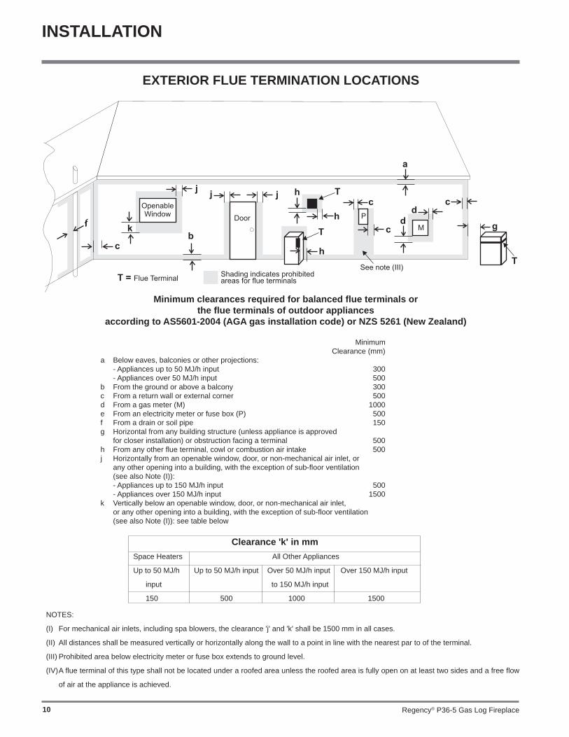
EXTERIOR FLUE TERMINATION LOCATIONS
Minimum clearances required for balanced fl ue terminals or the fl ue terminals of outdoor appliances
according to AS5601-2004 (AGA gas installation code) or NZS 5261 (New Zealand)
Minimum Clearance (mm)a Below eaves, balconies or other projections: - Appliances up to 50 MJ/h input 300 - Appliances over 50 MJ/h input 500b From the ground or above a balcony 300c From a return wall or external corner 500d From a gas meter (M) 1000e From an electricity meter or fuse box (P) 500f From a drain or soil pipe 150g Horizontal from any building structure (unless appliance is approved for closer installation) or obstruction facing a terminal 500h From any other fl ue terminal, cowl or combustion air intake 500j Horizontally from an openable window, door, or non-mechanical air inlet, or any other opening into a building, with the exception of sub-fl oor ventilation (see also Note (I)): - Appliances up to 150 MJ/h input 500 - Appliances over 150 MJ/h input 1500k Vertically below an openable window, door, or non-mechanical air inlet, or any other opening into a building, with the exception of sub-fl oor ventilation (see also Note (I)): see table below
NOTES:
(I) For mechanical air inlets, including spa blowers, the clearance 'j' and 'k' shall be 1500 mm in all cases.
(II) All distances shall be measured vertically or horizontally along the wall to a point in line with the nearest par to of the terminal.
(III) Prohibited area below electricity meter or fuse box extends to ground level.
(IV) A fl ue terminal of this type shall not be located under a roofed area unless the roofed area is fully open on at least two sides and a free fl ow
of air at the appliance is achieved.
Clearance 'k' in mmSpace Heaters All Other Appliances
Up to 50 MJ/h Up to 50 MJ/h input Over 50 MJ/h input Over 150 MJ/h input
input to 150 MJ/h input
150 500 1000 1500

Regency® P36-5 Gas Log Fireplace 11
INSTALLATION
FLUEINGRegency® Direct Vent System (Flex)
Horizontal Terminations Only
These fl ueing systems, in combination with the P36 Room Sealed Gas Fireplace, have been tested and listed as a Direct Vent type fl ue system by the Australian Gas Association. The location of the termination cap must conform to the requirements in the Flue Terminal Locations diagram in section "Exterior Flue Termination Locations."
Regency® Direct Vent (Flex) System Termination Kit (Part # 946-515) includes all the parts needed to install the P36 with a maximum run of 1200mm.
1) 175mm dia. fl exible liner (1200mm length)2) 100mm dia. fl exible liner (1200mm length)3) spring spacers (4)4) thimble (2)5) AstroCap termination cap (1)6) screws (12)7) tube of Mill Pac (1)8) plated screws (8)9) screws #8 x 1-1/2" Drill Point, Stainless Steel (4)
If longer runs are needed, the Regency® Direct Vent system (Flex) # 946-516 includes all the parts needed to install the P36 with a maximum 3.0m run.
1) 175mm dia. fl exible liner (3.0m length)2) 100mm dia. fl exible liner (3.0m length)3) spring spacers (7)4) thimble (2)5) AstroCap termination cap (1)6) screws (12)7) tube of Mill Pac (1)8) plated screws (8)9) screws #8 x 1-1/2" Drill Point, Stainless Steel (4)
Notes: 1) Liner sections should be continuous without any joints or seams.
2) Only Flex pipe purchased from Regency® may be used for Flex installations.
3) If you are installing the P36 into a Regency® Mantel Kit, use the minimum horizontal vent height (centre-line of 1029mm). Remember to include the mantel base in your calculations and to maintain the 32mm clearance (38mm with Flex) to the underside of the mantel top.
6-7/8"(173mm)
dia. Flue pipe
4" (102mm)dia. flue pipe
spring spacer
Termination Cap(Part# 946-578/P)
AstroCap
(patented)
Wall Thimble
Regency® P36-5 Gas Log Fireplace12
INSTALLATION
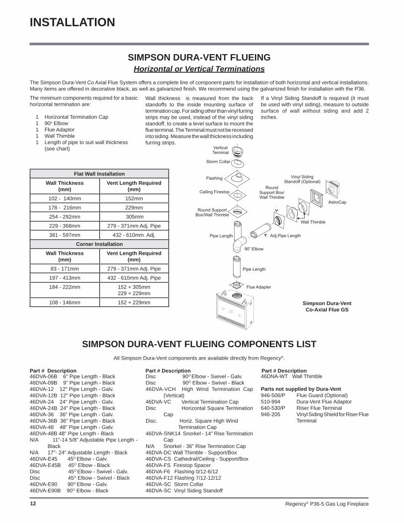
Simpson Dura-VentCo-Axial Flue GS
SIMPSON DURA-VENT FLUEING COMPONENTS LISTAll Simpson Dura-Vent components are available directly from Regency®.
Part # Description Part # Description Part # Description
SIMPSON DURA-VENT FLUEINGHorizontal or Vertical Terminations
The Simpson Dura-Vent Co Axial Flue System offers a complete line of component parts for installation of both horizontal and vertical installations. Many items are offered in decorative black, as well as galvanized fi nish. We recommend using the galvanized fi nish for installation with the P36.
The minimum components required for a basic horizontal termination are:
1 Horizontal Termination Cap 1 90o Elbow 1 Flue Adaptor 1 Wall Thimble 1 Length of pipe to suit wall thickness (see chart)
46DVA-06B 6" Pipe Length - Black 46DVA-09B 9" Pipe Length - Black 46DVA-12 12" Pipe Length - Galv.46DVA-12B 12" Pipe Length - Black 46DVA-24 24" Pipe Length - Galv.46DVA-24B 24" Pipe Length - Black 46DVA-36 36" Pipe Length - Galv. 46DVA-36B 36" Pipe Length - Black 46DVA-48 48" Pipe Length - Galv.46DVA-48B 48" Pipe Length - Black N/A 11"-14 5/8" Adjustable Pipe Length -
Black N/A 17"- 24" Adjustable Length - Black 46DVA-E45 45O Elbow - Galv.46DVA-E45B 45O Elbow - Black Disc 45O Elbow - Swivel - Galv.Disc 45O Elbow - Swivel - Black 46DVA-E90 90O Elbow - Galv.46DVA-E90B 90O Elbow - Black
Disc 90O Elbow - Swivel - Galv.Disc 90O Elbow - Swivel - Black 46DVA-VCH High Wind Termination Cap
(Vertical)46DVA-VC Vertical Termination CapDisc Horizontal Square Termination
CapDisc. Horiz. Square High Wind Termination Cap46DVA-SNK14 Snorkel - 14" Rise Termination
CapN/A Snorkel - 36" Rise Termination Cap46DVA-DC Wall Thimble - Support/Box 46DVA-CS Cathedral/Ceiling - Support/Box46DVA-FS Firestop Spacer46DVA-F6 Flashing 0/12-6/1246DVA-F12 Flashing 7/12-12/1246DVA-SC Storm Collar46DVA-SC Vinyl Siding Standoff
46DNA-WT Wall Thimble
Parts not supplied by Dura-Vent946-506/P Flue Guard (Optional)510-994 Dura-Vent Flue Adaptor640-530/P Riser Flue Terminal946-205 Vinyl Siding Shield for Riser Flue
Terminal
If a Vinyl Siding Standoff is required (it must be used with vinyl siding), measure to outside surface of wall without siding and add 2 inches.
Flat Wall InstallationWall Thickness
(mm)Vent Length Required
(mm)102 - 140mm 152mm
178 - 216mm 229mm
254 - 292mm 305mm
229 - 368mm 279 - 371mm Adj. Pipe
381 - 597mm 432 - 610mm Adj.
Corner InstallationWall Thickness
(mm) Vent Length Required
(mm)83 - 171mm 279 - 371mm Adj. Pipe
197 - 413mm 432 - 610mm Adj. Pipe
184 - 222mm 152 + 305mm229 + 229mm
108 - 146mm 152 + 229mm
Wall thickness is measured from the back standoffs to the inside mounting surface of termination cap. For siding other than vinyl furring strips may be used, instead of the vinyl siding standoff, to create a level surface to mount the fl ue terminal. The Terminal must not be recessed into siding. Measure the wall thickness including furring strips.

Regency® P36-5 Gas Log Fireplace 13
INSTALLATION
FLUEING ARRANGEMENTS - HORIZONTAL TERMINATIONSSIMPSON DURA-VENT DIRECT VENT GS SYSTEM and
REGENCY® DIRECT VENT SYSTEM (FLEX)(LPG & NG)
The diagram shows all allowable combinations of vertical runs with horizontal terminations, using one 90o elbow (two 45o elbows equalone 90o elbow).
Note: Must use optional fl ue adapter (Part # 510-994) when using Simpson Dura-Vent pipe.
Simpson Dura-Vent4" (102mm) inner diameter6-5/8" (168mm) outer diameter
Regency® Flex Vent4" (102mm) inner diameter6-7/8" (175mm) outer diameter
• Maintain clearances to combustibles as listed in section "Clearances."• Horizontal fl ue must be supported every 3 feet (0.9 meters).• Firestops are required at each fl oor level and whenever passing through a wall.
A fl ue guard should be used whenever the termination is lower than the specifi ed minimum or as per local codes.
Note: Regency® Co Axial Flue System (Flex) is only approved for horizontal terminations.

Regency® P36-5 Gas Log Fireplace14
FLUEING ARRANGEMENTS - HORIZONTAL TERMINATIONSSIMPSON DURA-VENT DIRECT FLUE SYSTEM and
REGENCY® CO AXIAL FLUE SYSTEM (FLEX)(LPG & NG)
The diagram below shows examples of horizontal termination arrangements using two 90o elbows (two 45o elbows equal one 90o elbow).
Note: 1) A maximum of two 90o elbows are permitted. 2) A minimum of 6 ft. (1.8m) vertical from base of unit is required if two 90o elbows are used. 3) Minimum distance between elbows is 2 ft. (0.6m). 4) Determine the permitted range of horizontal termination arrangements by using chart in section "Simpson Dura-vent Flueing." and deducting 3 ft. (0.9m) from the maximum horizontal distance for the second 90o elbow.
Simpson Dura-Vent4" (102mm) inner diameter6-5/8" (159mm) outer diameter
• Maintain clearances to combustibles as listed in section "Clearances."
• Horizontal fl ue must be supported every 3 feet (0.9 meters).
• Firestops are required at each fl oor level and whenever passing through a wall.
A fl ue guard should be used whenever the termination is lower than the specifi ed minimum or as per local codes.
If length "B" is increased, length "A" must be decreased by a corresponding amount.
INSTALLATION

Regency® P36-5 Gas Log Fireplace 15
INSTALLATION
FLUEING ARRANGEMENTS - VERTICAL TERMINATIONSSIMPSON DURA-VENT CO AXIAL FLUE SYSTEM (LPG & NG)
The P36 is approved for a 23 ft. (7.0m) vertical, with a maximum 12 ft. (3.7m) horizontal offset using two 90o elbows (two 45o elbows equal one 90o elbow) with Simpson Dura-Vent Co Axial Flue GS fl ue systems for LPG and NG, as per diagram 1.
The P36 is approved for a 37 ft. (11.3m) straight vertical, including a 20" (0.5m) horizontal offset using two 90o elbow (two 45o elbows equal one 90o elbow) with Simpson Dura-Vent Co Axial Flue GS fl ue systems for LPG and NG, as per the diagram 2.
• Flue must be supported at offsets• Maintain clearances to combustibles as listed in section "Clearances."
Note: Must use optional fl ue adapter when using Simpson Dura-Vent pipe (Part # 510-994).Note: Regency® Co Axial Flue System (Flex) is only approved for horizontal
terminations.
Diagram 1 Diagram 2

Regency® P36-5 Gas Log Fireplace16
The P36 is approved for a 37 ft. (11.3m) straight vertical, with Simpson Dura-Vent Co Axial Flue GS fl ue systems for LPG and NG, as per the diagram 3.
The shaded area in the diagram 3 shows all allowable combinations of straight vertical and offset to vertical terminations with Simpson Dura-Vent Co Axial Flue GS fl ue systems for LPG and NG. Maximum two 45o elbows allowed.
• Flue must be supported at offsets• Firestops are required at each fl oor level and whenever passing
through a wall.• Maintain clearances to combustibles as listed in section
"Clearances."
Diagram 3
INSTALLATION

Regency® P36-5 Gas Log Fireplace 17
INSTALLATION
Diagram 5
8) Slide the appliance and fl ue assembly towards the wall carefully inserting the fl ue pipe into the fl ue cap assembly. It is important that the fl ue pipe extends into the fl ue cap suffi cient distance so as to result in a minimum pipe overlap of 1-1/4 inches. Secure the connection between the fl ue pipe and the fl ue cap by attaching the two sheet metal strips extending from the fl ue cap assembly into the outer wall of the fl ue pipe. Use the two sheet metal screws provided to connect the strips to the pipe section. See Diagram 4.
9) Install wall thimble in the center of the 10" square and attach with wood screws (Diagram 5).
HORIZONTAL TERMINATIONS
Install the fl ue system according to the manufacturer's instructions included with the components.
1) Set the unit in its desired location. Check to determine if wall studs or roof rafters are in the way when the fl ueing system is attached. If this is the case, you may want to adjust the location of the unit. Rough in the gas preferably on the right side of the unit and the electrical (junction block is on the left side) on the left.
2) Co Axial Flue pipe and fi ttings are designed with special twist-lock connections to connect the fl ueing system to the appliance fl ue outlet. A twist-lock appliance adaptor is an available option that must be used in conjunction with the Simpson Dura-Vent Co Axial Flue GS system.
3) Put a bead of silicone inside the outer section of the adapter and a bead of Stove Mate on the inner collar. Slip the adapter over the existing inner and outer fl ue collar and fasten to the outer collar only with the 3 supplied screws (drilling pilot holes will make this easier). Level the fi replace and fasten it to the framing using nails or screws through the nailing strips.
4) Assemble the desired combination of pipe and elbows to the appliance adaptor and twist-lock for a solid connection.
Note: a) Twist-lock procedure: Four indentations,
located on the female ends of pipes and fi ttings, are designed to slide straight onto the male ends of adjacent pipes and fi ttings, by orienting the four pipe indentations so they match and slide in to the four entry slots on the male ends, Diagram 1. Push the pipe sections completely together, then twist-lock one section clockwise approximately one-quarter turn, until the two sections are fully locked. The female locking lugs will not be visible from the outside, on the Black Pipe or fi ttings. They may be located by examining the inside of the female ends.
Diagram 1
b) Horizontal runs of fl ue must be supported every three feet. Wall straps are available for this purpose.
5) Mark the wall for a 10" x 10" square hole. The center of the square hole should line up with the centerline of the horizontal pipe. Cut and frame the 10 inch square hole in the exterior wall where the fl ue will be terminated. If the wall being penetrated is constructed of non-combustible material, i.e. masonry block or concrete, a 7"(178mm) dia. (7-1/2"(191mm) dia. for fl ex) hole is acceptable.
Diagram 2
Note:
a) The horizontal run of fl ue must be level, or have a 1/4 inch rise for every 1 foot of run towards the termination. Never allow the fl ue to run downward. This could cause high temperatures and may present the possibility of a fi re.
b) The location of the horizontal flue termination on an exterior wall must meet all local and national building codes, and must not be blocked or obstructed. For External Flue Terminal Locations, see diagram in section "Exterior Flue Termination Locations."
6) The arrow on the flue cap should be pointing up. Insure that the 1-1/2" clearances to combustible materials are maintained. Install the termination cap, diagram 5.
The four wood screws provided should be replaced with appropriate fasteners for stucco, brick, concrete, or other types of sidings.
Note: If installing termination on a siding covered wall, a vinyl siding standoff or furring strips must be used to ensure that the termination is not recessed into the siding.
7) Before connecting the horizontal run of
fl ue pipe to the fl ue termination, slide the Wall Thimble (Part # 620-926) over the fl ue pipe.
Note: Apply sealant "Mill-Pac" to inner pipe and high temperature silicone sealant to outer pipe on every
twist-lock joint.
Note: With Dura-Vent , the minimum h e i g h t i s achieved by installing a 90 o e lbow directly to the fl ue adaptor.
Diagram 4
Diagram 3
Regency® P36-5 Gas Log Fireplace18
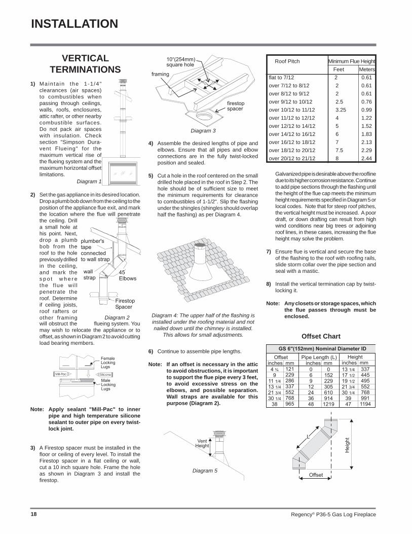
Offset Chart
Galvanized pipe is desirable above the roofl ine due to its higher corrosion resistance. Continue to add pipe sections through the fl ashing until the height of the fl ue cap meets the minimum height requirements specifi ed in Diagram 5 or local codes. Note that for steep roof pitches, the vertical height must be increased. A poor draft, or down drafting can result from high wind conditions near big trees or adjoining roof lines, in these cases, increasing the fl ue height may solve the problem.
7) Ensure fl ue is vertical and secure the base of the fl ashing to the roof with roofi ng rails, slide storm collar over the pipe section and seal with a mastic.
8) Install the vertical termination cap by twist-locking it.
Note: Any closets or storage spaces, which the fl ue passes through must be enclosed.
Diagram 3
Diagram 5
Diagram 1
Diagram 2
Note: Apply sealant "Mill-Pac" to inner pipe and high temperature silicone sealant to outer pipe on every twist-lock joint.
VERTICAL TERMINATIONS
1) Ma in ta in the 1 -1 /4" clearances (air spaces) to combustibles when passing through ceilings, walls, roofs, enclosures, attic rafter, or other nearby combustible surfaces. Do not pack air spaces with insulation. Check section "Simpson Dura-vent Flueing" for the maximum vertical rise of the fl ueing system and the maximum horizontal offset limitations.
2) Set the gas appliance in its desired location. Drop a plumb bob down from the ceiling to the position of the appliance fl ue exit, and mark the location where the fl ue will penetrate the ceiling. Drill a small hole at his point. Next, drop a plumb bob from the roof to the hole previously drilled in the ceiling, and mark the s p o t w h e r e the f lue wi l l penetrate the roof. Determine if ceiling joists, roof rafters or other framing
3) A Firestop spacer must be installed in the fl oor or ceiling of every level. To install the Firestop spacer in a fl at ceiling or wall, cut a 10 inch square hole. Frame the hole as shown in Diagram 3 and install the fi restop.
4) Assemble the desired lengths of pipe and elbows. Ensure that all pipes and elbow connections are in the fully twist-locked position and sealed.
5) Cut a hole in the roof centered on the small drilled hole placed in the roof in Step 2. The hole should be of suffi cient size to meet the minimum requirements for clearance to combustibles of 1-1/2". Slip the fl ashing under the shingles (shingles should overlap half the fl ashing) as per Diagram 4.
Roof Pitch Minimum Flue Height Feet Metersfl at to 7/12 2 0.61over 7/12 to 8/12 2 0.61over 8/12 to 9/12 2 0.61over 9/12 to 10/12 2.5 0.76over 10/12 to 11/12 3.25 0.99over 11/12 to 12/12 4 1.22over 12/12 to 14/12 5 1.52over 14/12 to 16/12 6 1.83over 16/12 to 18/12 7 2.13over 18/12 to 20/12 7.5 2.29over 20/12 to 21/12 8 2.44
Diagram 4: The upper half of the fl ashing is installed under the roofi ng material and not nailed down until the chimney is installed.
This allows for small adjustments.
6) Continue to assemble pipe lengths.
Note: If an offset is necessary in the attic to avoid obstructions, it is important to support the fl ue pipe every 3 feet, to avoid excessive stress on the elbows, and possible separation. Wall straps are available for this purpose (Diagram 2).
will obstruct the fl ueing system. You may wish to relocate the appliance or to offset, as shown in Diagram 2 to avoid cutting load bearing members.
INSTALLATION
Regency® P36-5 Gas Log Fireplace 19
Conversion Kit #513-968 from NG to LPG
THIS CONVERSION MUST BE DONE BY A QUALIFIED GAS FITTER IF IN DOUBT DO NOT DO THIS CONVERSION !!
1) Shut off the gas supply.
2) Remove the louvers (and bay door if it is installed).
3) Open the fl ush door and remove the door.
4) Remove the logs and embers (if used).
5) Remove the 2 screws holding the Burner
Remove the 2 screws, push Burner Assembly to the left and lift out.
6) Pull off the pilot cap to expose the pilot orifi ce.
7) Unscrew the pilot orifi ce with the allen key; then replace with the LPG pilot orifi ce and the pilot cap, provided in the kit.
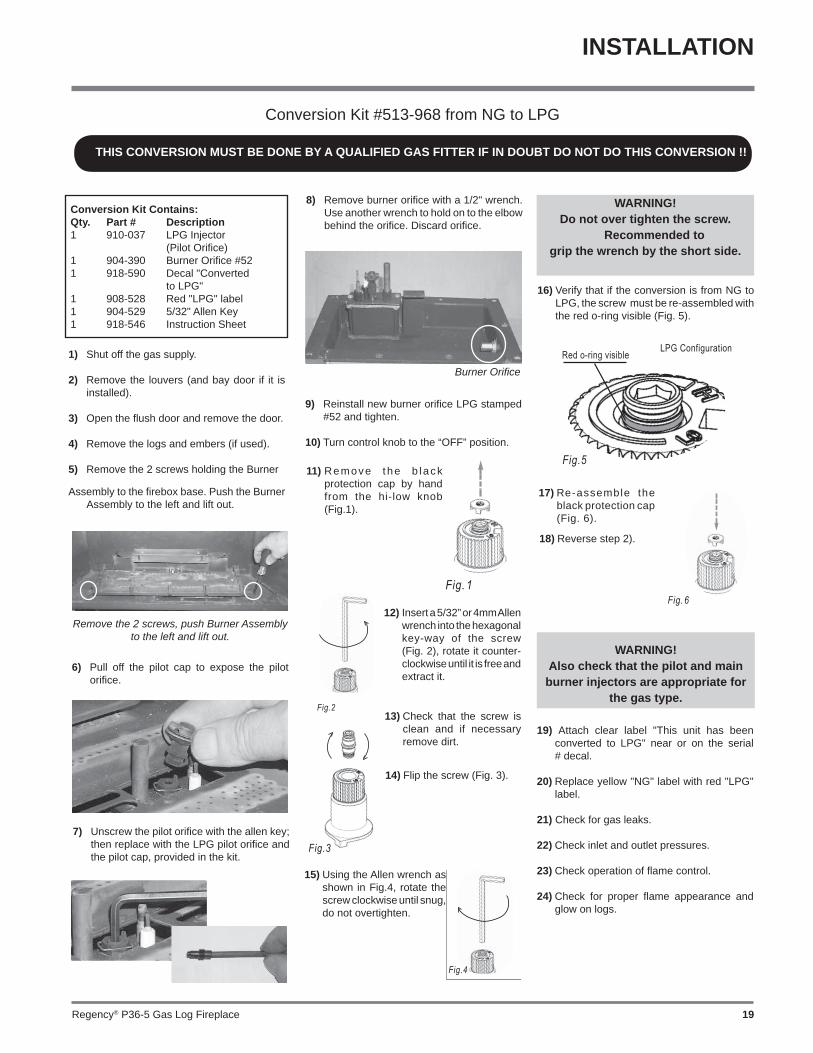
8) Remove burner orifi ce with a 1/2" wrench. Use another wrench to hold on to the elbow behind the orifi ce. Discard orifi ce.
Burner Orifi ce
9) Reinstall new burner orifi ce LPG stamped #52 and tighten.
10) Turn control knob to the “OFF” position.
Fig. 1
11) Remove the b lack protection cap by hand from the hi-low knob (Fig.1).
Fig.2
14) Flip the screw (Fig. 3).
Fig.4
Fig.3
15) Using the Allen wrench as shown in Fig.4, rotate the screw clockwise until snug, do not overtighten.
12) Insert a 5/32” or 4mm Allen wrench into the hexagonal key-way of the screw (Fig. 2), rotate it counter-clockwise until it is free and extract it.
13) Check that the screw is clean and if necessary remove dirt.
Conversion Kit Contains:Qty. Part # Description1 910-037 LPG Injector (Pilot Orifi ce)1 904-390 Burner Orifi ce #521 918-590 Decal "Converted to LPG"1 908-528 Red "LPG" label1 904-529 5/32" Allen Key1 918-546 Instruction Sheet
Assembly to the fi rebox base. Push the Burner Assembly to the left and lift out.
WARNING!Do not over tighten the screw.
Recommended togrip the wrench by the short side.
16) Verify that if the conversion is from NG to LPG, the screw must be re-assembled with the red o-ring visible (Fig. 5).
LPG ConfigurationRed o-ring visible
Fig.5
17) Re-assemble the black protection cap (Fig. 6).
Fig. 6
WARNING!Also check that the pilot and main
burner injectors are appropriate for the gas type.
19) Attach clear label "This unit has been converted to LPG" near or on the serial # decal.
20) Replace yellow "NG" label with red "LPG" label.
21) Check for gas leaks.
22) Check inlet and outlet pressures.
23) Check operation of fl ame control.
24) Check for proper fl ame appearance and glow on logs.
18) Reverse step 2).
INSTALLATION

Regency® P36-5 Gas Log Fireplace20
GAS PIPE PRESSURE TESTING
The appliance must be isolated from the gas supply piping system by closing its individual manual shut-off valve during any pressure testing of the gas supply piping system at test pressures equal to or less than 1/2 psig. (3.45 kPa). Disconnect piping from valve at pressures over 3.45 kPa.
The manifold pressure is controlled by a regulator built into the gas control, and should be checked at the pressure test point.
Note: To properly check gas pressure, both inlet and manifold pressures should be checked using the valve pressure ports on the valve.
1) Make sure the valve is in the "OFF" position.
2) Loosen the "IN" and/or "OUT" pressure tap(s), turning counterclockwise with a
1/8" wide fl at screwdriver.
3) Attach manometer to "IN" and/or "OUT" pressure tap(s) using a 5/16" ID hose.
P36-NG System Data
For 0 to 4500 feet altitudeBurner Inlet Orifi ce Sizes: #37( 2.65mm) Max. Input Rating 33 mjMin. Input Rating 20 mj Supply Pressure min.1.25 kPa Manifold Pressure (High) 0.9 kPa Electrical: 240 V A.C. System.Circulation Fan: variable speed 130 CFM.Log Set: Ceramic fi bre, 7 per set.Flue System: Simpson Dura-Vent Direct Flue System or Regency® Direct Flue System (Flex)
P36-LPG System Data
For 0 to 2000 feet altitude
Burner Inlet Orifi ce Sizes: #52 (1.6 mm) Max. Input Rating 31 mjMin. Input Rating 18 mj
For 0 to 4500 feet Altitude:
Supply Pressure min 2.75 kPa
Manifold Pressure (High) 2.7 kPa
Electrical: 240 V A.C. System.Circulation Fan: variable speed 130 CFM.Log Set: Ceramic fi bre, 7 per set.Flue System: Simpson Dura-Vent Co Axial Flue System
PILOT ADJUSTMENTPeriodically check the pilot fl ames. Correct fl ame pattern has three strong blue fl ames: 1 fl owing around the thermopile, 1 around the thermocouple and 1 fl owing across the burner (it does not have to be touching the burner).
Note: If you have an incorrect fl ame pattern, contact your Regency® dealer for further instructions.
Incorrect fl ame pattern will have small, probably yellow fl ames, not coming into proper contact with the rear burner or thermopile or thermocouple.
AERATION ADJUSTMENT
The air shutter can be adjusted by moving the adjusting wire up or down. The wire is accessed through the bottom louvre opening. Open the air shutter for a blue fl ame or close for a yellower fl ame. The burner aeration is factory set but may need adjusting due to either the local gas supply or altitude. This adjustment is performed by the gas fi tter.
Minimum Air Shutter Opening: 8 mm NG Full Open LPG
CAUTION: Carbon will be produced if air shutter is closed too much.
Note: Any damage due to carboning resulting from improperly setting the aeration controls is NOT covered under warranty.
Closed - Tall yellowOpen - Short Blue
GAS LINE INSTALLATION
The gas line can be brought through either the right or the left side of the appliance. The gas valve is situated on the right hand side of the unit and the gas inlet is on the right hand side of the valve.
Note: If the gas line is being installed from the left side, be sure to leave room to accommodate servicing of the fan.
The gas line connection may be made of rigid pipe, copper pipe or an approved fl ex connector. (If you are using rigid pipe, ensure that the valve can be removed for servicing.) Since some municipalities have additional local codes it is always best to consult with your local authorities and the AS5601-2004 or NZS 5261 installation code.
When using copper or fl ex connectors use only approved fi ttings. Always provide a union so that gas lines can be easily disconnected for servicing. Flare nuts for copper lines and fl ex connectors are usually considered to meet this requirement.
Important: Always check for gas leaks with a soap and water solution or gas leak detector. Do not use open fl ame for leak testing.
INSTALLATION

Regency® P36-5 Gas Log Fireplace 21
OPTIONAL BRICK PANELS
1) Undo the bottom 2 door latches and open and remove glass door. Remove logs.
Note: The logs must not be in the unit.
2) Insert the back brick panel fi rst by carefully slipping it between the back wall of the fi rebox and the rear log bracket.
4) Light the pilot and turn the valve to "ON" position.
5) The pressure check should be carried out with the unit burning and the setting should be within the limits specifi ed on the safety label.
6) When fi nished reading manometer, turn off the gas valve, disconnect the hose and tighten the screw (clockwise) with a 1/8" fl at screwdriver. Note: Screw should be snug, but do not over tighten.
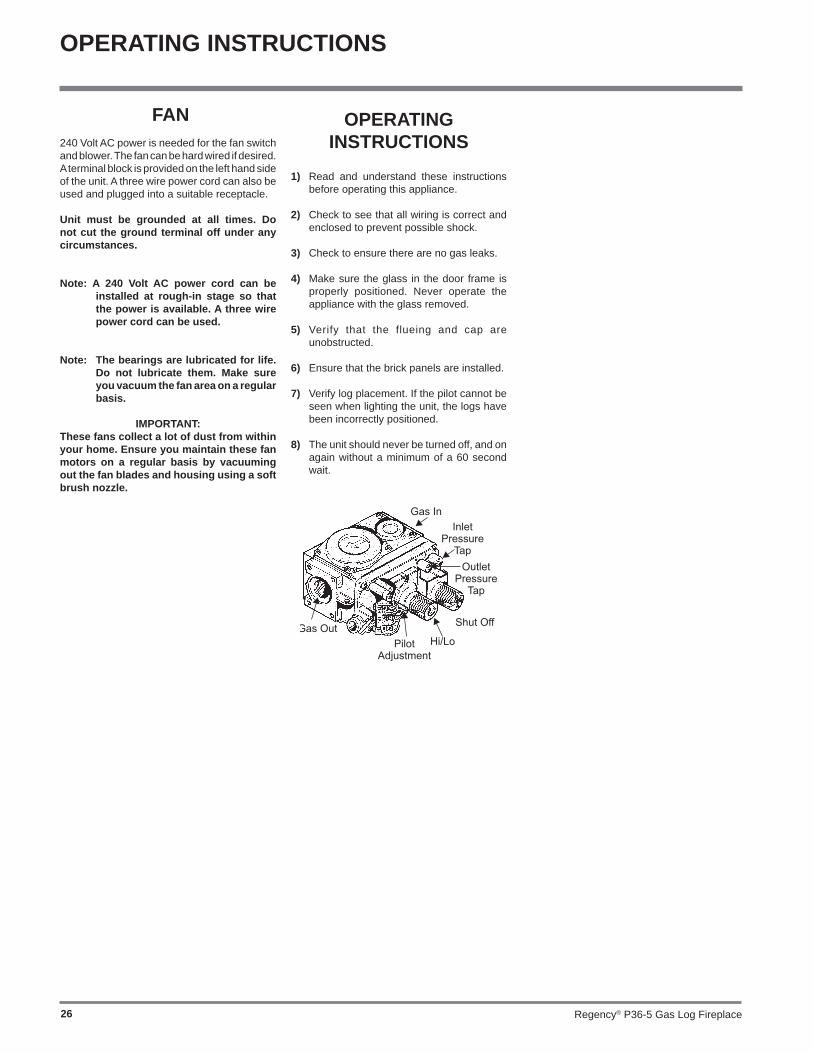
S.I.T. VALVE DESCRIPTION
1) Gas on/off knob2) Manual high/low adjustment3) Pilot Adjustment4) Thermocouple Connection - option5) Outlet Pressure Tap6) Inlet Pressure Tap7) Pilot Outlet8) Main Gas Outlet9) Alternative TC Connection Point
3) Put the side panels in next. Slide them in from the front and push them fl at up against the wall. Be very careful not to scratch them on the fi rebox hardware.
4) Install the 2 brick retaining clips, one on each side.
LOG SET INSTALLATION
Read the instructions below carefully and refer to the diagrams. If logs are broken do not use the unit until they are replaced. Broken logs can interfere with the pilot operation.
The gas log kit (Part # 512-930) contains the following pieces:
a) 02-49 Rear Log b) 02-55 Middle Left Log c) 02-50 Front Left Log d) 02-53 Center Left Log e) 02-51 Front Bottom Log f) 02-54 Center Right Log g) 02-52 Middle Right Log h) Embers 902-156i) Vermiculite 902-179
NOTE: If you will be installing the optional Brick Panels, install the Brick Panels prior to installing the logs.
1) Carefully remove the logs from the box and unwrap them. The logs are fragile, handle with care - do not force into position.
2) Sprinkle the vermiculite around the fi rebox base.
Vermiculite Vermiculite Vermiculite
The "02" refer numbers (i.e. 02-49) are molded into the rear of each log.
3) Place the Log 02-49 on the rear log support pins with the fl at side to the back.
INSTALLATION

Regency® P36-5 Gas Log Fireplace22
9) Place Log 02-52 between Logs 02-51 and 02-49 and on the indentation on Log 02-54. The bottom right end sits behind the rear grate tab.
Log indentation
Photo shows rear grate tab. Log 02-51 was removed to show
the positioning of Log 02-52.
RearGrate Tab
02-52
02-49
02-5102-54
02-52
02-54
5th Grate Tab
Rear Bracket
Front Brackets
Notch
02-55
02-50
02-54
5) Position Log 02-53 across the cutouts in Logs 02-49 and 02-51 with the notch on the left side of the log fi tting into the 2nd grate tab.
Cutouts2nd Grate Tab
02-53
02-49
02-51
02-49
02-5102-53
02-49
02-5102-53
02-55
02-53
02-50
02-55
02-53
02-50
02-55
02-53
02-49
02-51
02-5302-51 02-54
NotchBracketBracket
02-49
02-51
02-49
02-51
4) Place Log 02-51 on the front right side of the burner. Push the back of the log against the 2 brackets with the notch on the bottom right side of the log fi tting into the right side of the grate.
6) Place the bottom left front edge of Log 02-55 against the rear bracket on the burner
tray and rest the log on the cutout on Log 02-53.
7) Sit Log 02-50 on the front left side of the burner. Push the back of the log against the 2 front brackets with the notch on the bottom of the log fi tting into the fi rst grate tab.
8) Position Log 02-54 across the cutouts in Logs 02-51 and 02-53. The notch in the bottom right end fi tting against the 5th grate tab.
INSTALLATION

Regency® P36-5 Gas Log Fireplace 23
STANDARD FLUSH DOOR
Diagram 3
Use the hook to pull the spring out until you can put the hook into the slot on the bottom door bracket. Repeat for 2nd spring. See diagram 3.
Diagram 2
The standard fl ush door comes with a black frame. To install the frame, simply hook the top door fl ange onto the top of the unit and swing the door towards the unit, diagram 1.
Be careful that the glass gasket does not roll up; there must be a gap between the gasket and the door lip to ensure that the door sits securely on the unit. Diagram 2.
Diagram 1 To remove the fl ush door, reverse the above steps.
Optional Flush Trim
Attach the round magnets to the back of the top trim piece and to the bottom trim piece, then attach trim to the top and bottom of Flush door.
Flush Louvres / Premium Flush Front
1) Install the top louvre by sliding the two bracket clips into the brackets located underneath the top of the fi rebox.
2) The bottom louvre has a hinge that is attached (2 screws per hinge) to the lip on bottom of the unit.
Note: Top and bottom louvres are different.
10) Place the embers on the front of the burner tray in the places shown on the photo.
11) Test fi re to ensure proper light off (make sure fl ame fl ows smoothly from one end of burner to the other). If there is any fl ame hesitation, check that area for any blockage of the burner ports.
12) Install fl ush glass and bay glass (if used) as per instructions in this manual.
Place embers in these 3 locations on the burner tray.
Embers
02-50
02-55
02-49
02-5302-51
02-54
02-52
INSTALLATION
Note: If the optional premium fl ush front is used, the fan must run at
minimum speed to prevent the unit from over heating. Over heating will cause automatic shutdown via the thermodisc safety switch.

Regency® P36-5 Gas Log Fireplace24
Option 1: WALL SWITCH
1) Run supplied 15' of wire through the right or left side gas inlet opening. Be careful not to damage wire.
Note: We recommend a maximum of 15' of wire but if you wish to go with a longer run, use the Thermostat Wire Table.
2) Connect wire to supplied wall switch and install into the receptacle box.
Option 3: WALL THERMOSTAT
A wall thermostat may be installed if desired, connect the wires as per the wiring diagram. Use chart below to determine the maximum wire length.
Note: Preferable if the thermostat is installed on an interior wall.
Regency® offers a programmable thermostat but any CSA, UCL or UL approved millivolt thermostat, 250-750 millivolt rated non-anticipator type thermostat may be used.
Option 2: REMOTE CONTROL
Use the Regency® Remote Control Kit approved for this unit. Use of other systems may void your warranty.
The remote control kit comes with a hand held transmitter, a receiver and a wall mounting plate.
1) Choose a convenient location on the wall to install the receiver and the receptacle box (protection from extreme heat is very important). Run wires from the fi replace to that location. Use Thermostat Wire Table.
2) Connect the two wires to the gas valve. See diagram below.
3) Install 4 AA batteries in the receiver and 4 AA batteries into the transmitter hand held. Install the receiver and its cover in the wall. Switch the hand held remote transmitter to "remote" mode. The remote control is now ready for operation. Thermostat Wire Table
14 GA.16 GA.18 GA.20 GA.22 GA.
15.24 m9.75 m6.10 m3.66 m2.71 m
Recommended Maximum Lead Length (Two-Wire) When Using Wall Thermostat (CP-2 System)
Wire Size Max. Length
INSTALLATION
CAUTIONDo not connect millivolt
wall switch wires for gas appliance to a 240V power
supply.
CAUTIONDo not connect millivolt
wall switch wires for gas appliance to a 240V power
supply.
CAUTIONDo not connect millivolt
wall switch wires for gas appliance to a 240V power
supply.

Regency® P36-5 Gas Log Fireplace 25
STANDARD WIRING
INSTALLATION
WARNING: Electrical Grounding InstructionsThis appliance is equipped with a three pronged (grounding) plug for your protection against shock hazard and should be plugged directly into a properly grounded three-prong receptacle. Do not cut or remove the grounding prong from this plug.
CAUTION: Label all wires prior to disconnection when servicing controls. Wiring errors can cause improper and dangerous operation.
This heater does not require a 240V A.C. supply for the gas control to operate. A 240V A.C. power supply is needed for the fan/blower operation.
Caution: Ensure that the wires do not touch any hot surfaces and are away from sharp edges.
Note: If the optional premium fl ush front is used, the fan must run at
minimum speed to prevent the unit from over heating. Over heating will cause automatic shutdown via the thermodisc safety switch.
Regency® P36-5 Gas Log Fireplace26
OPERATING INSTRUCTIONS
OPERATING INSTRUCTIONS
1) Read and understand these instructions before operating this appliance.
2) Check to see that all wiring is correct and enclosed to prevent possible shock.
3) Check to ensure there are no gas leaks.
4) Make sure the glass in the door frame is properly positioned. Never operate the appliance with the glass removed.
5) Verify that the flueing and cap are unobstructed.
6) Ensure that the brick panels are installed.
7) Verify log placement. If the pilot cannot be seen when lighting the unit, the logs have been incorrectly positioned.
8) The unit should never be turned off, and on again without a minimum of a 60 second wait.
FAN240 Volt AC power is needed for the fan switch and blower. The fan can be hard wired if desired. A terminal block is provided on the left hand side of the unit. A three wire power cord can also be used and plugged into a suitable receptacle.
Unit must be grounded at all times. Do not cut the ground terminal off under any circumstances.
Note: A 240 Volt AC power cord can be installed at rough-in stage so that the power is available. A three wire power cord can be used.
Note: The bearings are lubricated for life. Do not lubricate them. Make sure you vacuum the fan area on a regular basis.
IMPORTANT:These fans collect a lot of dust from within your home. Ensure you maintain these fan motors on a regular basis by vacuuming out the fan blades and housing using a soft brush nozzle.

Regency® P36-5 Gas Log Fireplace 27
OPERATING INSTRUCTIONS
During the fi rst few fi res, a white fi lm may develop on the glass front as part of the curing process. The glass should be cleaned or the fi lm will bake on and become very diffi cult to remove. Use a non-abrasive cleaner and NEVER clean the glass while it is hot.
NORMAL OPERATING SOUNDS OF GAS
APPLIANCESIt is possible that you will hear some sounds from your gas appliance. This is perfectly normal due to the fact that there are various gauges and types of steel used within your appliance. Listed below are some examples. All are normal operating sounds and should not be considered as defects in your appliance.
Blower: Regency® gas appliances use high tech blowers to push heated air farther into the room. It is not unusual for the fan to make a "whirring" sound when ON. This sound will increase or decrease in volume depending on the speed setting of your fan speed control.
Burner Tray: The burner tray is positioned directly under the burner tube(s) and logs and is made of a different gauge material from the rest of the fi rebox and body. Therefore, the varying thicknesses of steel will expand and contract at slightly different rates which can cause "ticking" and "cracking" sounds. You should also be aware that as there are temperature changes within the unit these sounds will likely re-occur. Again, this is normal for steel fi reboxes.
Blower Thermodisc: When this thermally activated switch turns ON it will create a small "clicking" sound. This is the switch contacts closing and is normal.
Pilot Flame: While the pilot fl ame is on it can make a very slight "whisper" sound.
Gas Control Valve: As the gas control valve turns ON and OFF, a dull clicking sound may be audible, this is normal operation of a gas regulator or valve.
Unit Body/Firebox: Different types and thicknesses of steel will expand and contract at different rates resulting in some "cracking" and "ticking" sounds will be heard throughout the cycling process.
1) Push in gas control knob slightly and turn to “PILOT” position.
2) Push in control knob all the way and hold in until the pilot lights up. Continue to hold the control knob in for about 20 seconds after the pilot is lit. Release knob.
3) Push in gas control knob slightly and turn to "ON" position.
4) Turn ON the fl ame switch.
SHUTDOWN PROCEDURE
1) Turn OFF the fl ame switch.
2) Push in gas control knob slightly and turn to "OFF" position.
Gas Inlet
FIRST FIREThe fi rst fi re in your stove is part of the paint curing process. To ensure that the paint is properly cured, it is recommended that you burn your fi replace, on high, for at least four (4) hours the fi rst time you use it - with the fan off.
When fi rst operated, the unit will release an odour caused by the curing of the paint, the burning off of any oils remaining from manufacturing. Smoke detectors in the house may go off at this time. Open a few windows to ventilate the room for a couple of hours.
The glass panel may require cleaning after the unit has cooled down.
DO NOT ATTEMPT TO CLEAN THE GLASS WHILE IT IS HOT.
Note: When the glass is cold and the appliance is lit, it may cause condensation and fog the glass. This condensation is normal and will disappear in a few minutes as the glass heats up.
DO NOT BURN THE APPLIANCE WITHOUT THE GLASS FRONT IN PLACE.
LIGHTING PROCEDURE

Regency® P36-5 Gas Log Fireplace28
MAINTENANCE INSTRUCTIONS
1) Always turn off the gas valve before cleaning. For relighting, refer to lighting instructions. Keep the burner and control compartment clean by brushing and vacuuming at least once a year. When cleaning the logs, use a soft clean paint brush as the logs are fragile and easily damaged.
2) Clean appliance and door with a damp cloth (never when unit is hot). Never use an abrasive cleaner. The glass should be cleaned with a gas fi replace glass cleaner. The glass should be cleaned when it starts looking cloudy.
3) The heater is fi nished in a heat resistant paint and should only be refi nished with heat resistant paint. Regency® uses StoveBright Paint - Metallic Black #6309.
4) Make a periodic check of burner for proper position and condition. Visually check the fl ame of the burner periodically, making sure the fl ames are steady; not lifting or fl oating. If there is a problem, call an authorized service person.
5) The appliance and fl ueing system must be inspected before use, and at least annually, by an authorized fi eld service person, to ensure that the fl ow of combustion and ventilation air is not obstructed.
Note: Never operate the appliance without the glass properly secured in place.
6) Do not use this appliance if any part has been under water. Immediately call an authorized service technician to inspect the appliance and to replace nay part of the control system and any gas control which has been under water.
7) Verify operation after servicing.
General Flue Maintenance
Conduct an inspection of the fl ueing system semi-annually. Recommended areas to inspect as follows:
1) Check the Flueing System for corrosion in areas that are exposed to the elements. These will appear as rust spots or streaks, and in extreme cases, holes. These components should be replaced immediately.
2) Remove the Cap, and shine a fl ashlight down the Flue. Remove any bird nests, or other foreign material.
COPY OF THE LIGHTING PLATE INSTRUCTIONS
OPERATING INSTRUCTIONS
���������������� ����
�������������������������� �����
������������� ������������������������������������������������������������������������������� !��"#�$�%%&'��(��������)��"*+,��%,,�������$����)��$"�*%+�-
�� ����� � �� � ���� � �������
�� ����� ��������������� ������������������ ����� ��� ��� ��������
��������� ������������ �������� ������������������ ����� ���� ���!����"��� ������ ����#�������$���%��� ���!��$"���� ���%!���������$� �����&��$������!"����'����������� �(���'�������$��� ��������� ��� ������ ��� ��� ���� ��� ��$ ����� ��! ��� ��� ������������ ��!����������
������������������
!������ � ����� � ���� �� ����� ���������� � � ����� �� ��� ������ "� ���������� �� � ����#� ������� �� � ������������� $������
%�%&'&�()*+�),*��� ��������������� �� ����� ��� �����������% ���� ��� �� ��� � $�� ��� �� � ������ � ���� ��� � ���� ��� � �-� �� ����� ���� �������� � ��� � � ��� �� � ������
"+!����.�)�/0�12&((�*!13 .������ ���� ��� ������ ����� ����� 3 .���������������� � ������������#��������� ����� ��� � ����������������
3 )�� ���� ��� ����� ����� ���� �� �� ������ �� � ��������� ��� �� ������� � ���� �� �� �4�� �������������
3 )�� ���� ������� � ���� ����� ����� �� �#� ����� �� � ��� � � ���� ���
5�0� ������������������� ���� ������ ������ �������������������, - ���� �������)�� �� ��������������� ���� ������ �����������#� ���4�� ���� ��� � ���� ��#� ����� �6������ �� � �-�� � � ���������� ��� � ����� � � �� � ���� ���� � ����� ��� �� ��� ��� $ �������
.�.�� ���� �� � ����� � ����� � ��� ���� ������� � �� ��� �� ��� ��� � )�� ���� ������� �� 6������ �� � �-�� � � ��������� ����� ��� �� � � ����� � ���� ��� � ��� ���� ��������� ������������� ������������� �������� ������ ���� � �� ��� ���� ��
����� � ����� � � ��� �� ��� ���� ���� ��� � ����������������� �������� ������� � �� � ��-������� ���� �� 6��� � �������������� - ���������� ����
��������������� ��� ��������������
)�*���+ �" �� $� �� "����� ���� ��� ��� ���� �,�� � % � "��� ���,��������� ����� ������!������ $���!�%����������-�� �������"��"������������� ���� ���%�$-�� ��� %�� ��� ���%������������� ����������������-�� �������� $���!��*�"�� � �������.���"���� ��������� �����$�$ �� � ��� ���������� /�� ����� ���� �� �$$� �������"���� ��������� �&����"��$��� �����%��������!��� ��!�����������
7�83�9:�
/��� ���� ����� ���� �� � ����� ������� ������ �� ���� �� � ������ ��� ���� �- � �� ��
1��;� ' ��� �� � ��� ��� ������������ ���- � ��� ����� ��� ��
�� ����� ��� ���� �������� ����� ��������� ���� ����� ��� <�)(�=� ��������
�� ��������������������������� ������������������������� � ������������� ���5������ ���������� ����������������������������>�� ��������� ���� � �������������' � �� �����
:� ����� ��� ���� �������� ����� ��������� �������� ��� �,�� ��������
?� ����� ,� �� � ���� � �������
Gas Inlet

Regency® P36-5 Gas Log Fireplace 29
OPERATING INSTRUCTIONS
3) Check for evidences of excessive condensation, such as water droplets forming in the inner liner, and subsequently dripping out the joints, Continuous condensation can cause corrosion of caps, pipe, and fi ttings. It may be caused by having excessive lateral runs, too many elbows, and exterior portions of the system being exposed to cold weather.
4) Inspect joints, to verify that no pipe sections or fi ttings have been disturbed, and consequently loosened. Also check mechanical supports such as Wall Straps, or plumbers' tape for rigidity.
GOLD-PLATED & BRASS
LOUVRES OR TRIM
The 24 carat gold plated or brass fi nish on the trim requires little maintenance, and need only be cleaned with a damp cloth. DO NOT use abrasive materials or chemical cleaners, as they may harm the fi nish and void the warranty. Clean any fi ngerprints off before turning the unit on. If the top louvres start to discolour, check the door gasket seal and replace if necessary.
LOG REPLACEMENTThe unit should never be used with broken logs. Turn off the gas valve and allow the unit to cool before opening door and carefully remove the logs. (The pilot light generates enough heat to burn someone.) If for any reason a log should need replacement, you must use the proper replacement log. The position of these logs must be as shown in the diagrams under Log Installation.
Note: Improper positioning of logs may create carbon build-up and will severely alter the unit's performance which is not covered under warranty.
THERMOPILE / THERMOCOUPLE
1) Open the bottom louvres.
2) Loosen the thermocouple or thermopile with a 7/16" spanner.
3) Disconnect thermocouple by loosening nut from the valve with a 9mm spanner. Disconnect thermopile by loosening 2 screws marked TP on the valve.
4) Drop the thermocouple or thermopile down from the bracket and pull it out of the unit.
5) Reinstall the new ones in reverse order.
GLASS GASKET If the glass gasket requires replacement use a tadpole glass gasket for the Flush Front (Part # 936-155).
DOOR GLASSYour Regency® fi replace is supplied with high temperature, 5 mm Neoceram ceramic glass that will withstand the highest heat that your unit will produce. If your glass requires cleaning, we recommend using an approved glass cleaner available at all authorized dealers. Do not use abrasive materials. Do not clean the glass when hot.
In the event that you break your glass by impact, purchase your replacement from an authorized Regency® dealer only, and follow our step-by-step instructions for replacement.
WARNING: Do not operate the appliance with the glass panels removed, cracked or broken. Replacement of the glass panels should be done by a licensed or qualifi ed service person.
Caution: Wear gloves when removing damaged or broken glass.
Flush Glass Replacement
Remove the fl ush door front (as per instructions in section "Standard Flush Door"). Remove the 4 glass clips from each corner. Slide in the new replacement glass. Push the 4 glass clips back onto the frame. The glass must have a gasket around it.
Regency® P36-5 Gas Log Fireplace30
MAINTENANCE
FAN REMOVAL
1) Shut the power off.
2) Open the bottom louvre door.
3) Remove the screen door
4) Remove the fl ush glass door (see p 23).
5) Remove 2 phillips screws located in the lower left of the unit - to release the spill switch (see Diagrams 1 & 2).
5) Remove 2 phillips screws located near the base of the burner and fan on/off switch (see Diagram 3).
6) Move burner/fan to access and unclip wire harness (see Diagram 4).
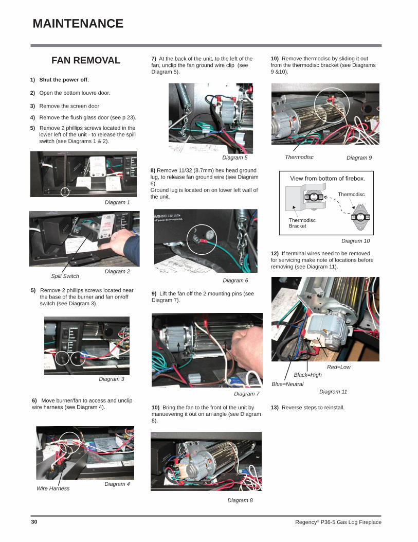
7) At the back of the unit, to the left of the fan, unclip the fan ground wire clip (see Diagram 5).
9) Lift the fan off the 2 mounting pins (see Diagram 7).
10) Bring the fan to the front of the unit by manuevering it out on an angle (see Diagram 8).
10) Remove thermodisc by sliding it out from the thermodisc bracket (see Diagrams 9 &10).
12) If terminal wires need to be removed for servicing make note of locations before removing (see Diagram 11).
13) Reverse steps to reinstall.
8) Remove 11/32 (8.7mm) hex head ground lug, to release fan ground wire (see Diagram 6).Ground lug is located on on lower left wall of the unit.
Spill SwitchDiagram 2
Diagram 1
Diagram 3
Wire HarnessDiagram 4
Diagram 5
Diagram 6
Diagram 7 Diagram 11Blue=Neutral
Black=HighRed=Low
Diagram 8
Diagram 9Thermodisc
Diagram 10
Regency® P36-5 Gas Log Fireplace 31
10) Undo the pilot tube from the valve with a 7/16" spanner.
11) Undo the quick drop out thermocouple nut on the valve with a 9mm (metric) spanner.
12) Remove the Piezo igniter wire and push button assembly.
13) Undo the "gas out" fl are nut with a 13/16" spanner.
14) Undo the "gas out" fl are fi tting with an 11/16" spanner.
15) Remove the 4 Phillips head screws from the sides of the valve bracket and remove valve.
Hint: If you are using black pipe, ensure that there is a union by the valve, otherwise removal will be almost impossible.
INSTALLING VALVE1) Attach the valve to the valve bracket with
the 4 (m5x8 metric) screws provided.
2) Reconnect the "gas out" fl are fi tting with an 11/16" spanner.
3) Reconnect the "gas out" fl are nut with a 13/16" spanner.
4) Install piezo ignitor push button assembly and reconnect wire.
5) Reconnect the quick drop out thermocouple nut with a 9mm spanner.
6) Reconnect the pilot tube nut with a 7/16" spanner.
7) Scrape off the old gasket from the fl oor of the fi rebox and from the valve tray assembly.
8) Install a new gasket and reinstall the valve tray assembly.
Note: Failure to install a new gasket may severely affect the appliance performance.
9) Reinstall the 10 hold down screws.
10) Hook up the 2 TP and 2 TH wires to the appropriate connections on the valve.
11) Reinstall the front log stand.
12) Install Burner/grate assembly
13) Hook up the gas line and check for gas leaks with a soap and water solution or a gas leak detector. (Do not use open fl ame for leak testing.)
14) Fire up the unit temporarily
15) Check the manifold pressure.
16) Reinstall the logs and brick panels as needed.
17) Close the door and replace the louvres.
18) Fire up the unit again and check for proper fl ame appearance and glow on logs.
REMOVING VALVE1) Shut off the gas supply.
2) Remove the louvres (and bay door if it is on).
3) Open the fl ush door and remove the door.
4) Remove the logs.
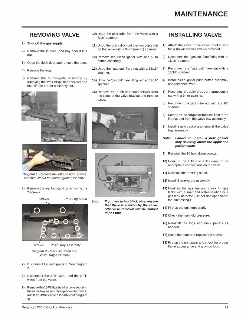
5) Remove the burner/grate assembly by removing the two Phillips head screws and then lift the burner assembly out.
Diagram 1: Remove the left and right screws and then lift out the burner/grate assembly.
6) Remove the rear log stand by removing the 2 screws.
Diagram 2: Rear Log Stand andValve Tray Assembly
screws Valve Tray Assembly
Rear Log Standscrews
7) Disconnect the inlet gas line. See diagram 2.
8) Disconnect the 2 TP wires and the 2 TH wires from the valve.
9) Remove the 10 Phillips head screws securing the valve tray assembly in place (diagram 2) and then lift the entire assembly out diagram 3).
MAINTENANCE

Regency® P36-5 Gas Log Fireplace32
34
BRICK PANEL SET
31
30
20
14
22
24
28
27
43
76
8
23
23
30
17
DOORS & LOUVERS PLEASE
33
35REFER SEPARATE SECTION
1142
15
37
36
24
10
9
PARTS LIST
MAIN ASSEMBLY
Part # Description
1) 910-142 Thermodisc-Fan Auto ON/OFF2) * Thermodisc Bracket3) 948-045 Chain4) 948-025 Spring6) 510-125 Terminal Block Housing7) 910-006 Terminal Block8) 510-126 Terminal Block Cover9) 910-140 Fan Switch HIGH/OFF/LOW10) 910-246 Burner Switch ON/OFF12) 910-169/P Fan Motor 910-520 Wire Harness 910-714 Power Cord (240 V)
14) 510-026 Hinge Bracket - Left/Right15) 948-253 Door Handle17) * Wire Holder Clip20) 510-033 Top Nailing Strip22) 510-153 Baffl e Plate23) 510-011 Standoff - Top24) 511-044 Standoff - Side/Back27) * Outer Flue Collar28) * Inner Flue Collar Assembly30) * Gasket for Flue Collar31) * Flue Mounting Plate
513-901 Brick Panel Set - Standard Brown 513-902 Brick Panel Set - Standard Red 513-903 Brick Panel Set - Herringbone Brown 513-904 Brick Panel Set - Herringbone Red33) * Brick Panel - Back34) * Brick Panel - Left35) * Brick Panel - Right
36) 910-073 Spark Generator Battery Holder37) 910-074 Spark Generator Switch c/w Wire
511-031 Brick Clip (each)
918-538 Manual 513-968 Conversion Kit - NG to LPG
*Not available as a replacement part.

Regency® P36-5 Gas Log Fireplace 33
BURNER ASSEMBLY & LOG SET
Part # Description
PARTS LIST
513-560/P Valve Assy - NG 513-562/P Valve Assy - LPG52) * Valve Tray -NG53) 430-055 Gasket - Valve Access Plate54) 910-421 Pilot ON/OFF 3" Extension Knob55) 910-422 HI/LOW 3" Extension Knob57) 910-478 S.I.T. Valve - NG/LPG58) * Valve Bracket59) * Firebox Base65) * Pilot Bracket66) 910-038 Pilot Assy-NG 3 way fl ame-S.I.T. 910-039 Pilot Assy-LPG 3 way fl ame-S.I.T. 904-240 Orifi ce #37 - NG (Burner) 904-390 Orifi ce #52 - LPG (Burner) 910-036 Pilot Orifi ce - NG 910-037 Pilot Orifi ce - LPG 936-170 Orifi ce Gasket67) * Pilot Holder68) W840470 Pilot Assembly Gasket
79) 514-535 Burner Assy - NG82) 511-030 Burner Grate Assy84) * Rear Log Support Assy85) 512-930 Log Set86) 910-386 Thermocouple87) 910-341 Thermopile88) 910-096 Pilot Hood (3-way)
92) * Rear Log93) * Middle Right Log94) * Front Left Log95) * Center Left Log96) * Center Right Log97) * Front Bottom Log98) * Middle Left Log
*Not available as a replacement part.
92
93
95 96
97
9894

Regency® P36-5 Gas Log Fireplace34
FLUSH FRONT ACCESSORIES
Part # Description
PARTS LIST
132) 512-518 Flush Door Assembly135) 940-090/P Glass (Flush)136) 936-155 Glass Gasket (Tadpole) 904-691 U-Clip (each)
510-920 Flush Louvres - Gold/Black 510-921 Flush Louvres - Brass/Black 510-922 Flush Louvres - Black 510-923 Flush Louvres - Steel/Black138) * Flush Louvre Assy-Top139) * Flush Louvre Assy-Btm
510-932 Flush Glass Trim - Gold (2/Set)
150) * Flush Glass Trim-Gold
904-196 Magnet (1" round)
510-947 Flush Glass Trim - Steel (2/Set)152) * Flush Glass Trim-Brass 904-196 Magnet (1" round) 510-986 Finishing Trim (3 piece) - Black 510-909 Finishing Trim (3 piece) - Steel 510-910 Finishing Trim (4 piece) - Steel157) * Finishing Trim Left 158) * Finishing Trim Top159) * Finishing Trim Right 160) * Finishing Trim Bottom
161) 513-949 Flush Door Screen Pkg.
*Not available as a replacement part.
Regency® P36-5 Gas Log Fireplace 35
PARTS LIST
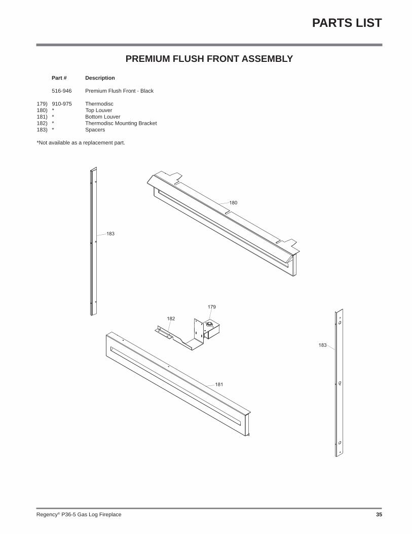
PREMIUM FLUSH FRONT ASSEMBLY
Part # Description
516-946 Premium Flush Front - Black 179) 910-975 Thermodisc 180) * Top Louver181) * Bottom Louver182) * Thermodisc Mounting Bracket183) * Spacers
*Not available as a replacement part.

Regency® P36-5 Gas Log Fireplace36
NOTES
________________________________________________________________________________________________________________________________________________________________________________________________________________________________________________________________________________________________________________________________________________________________________________________________________________________________________________________________________________________________________________________________________________________________________________________________________________________________________________________________________________________________________________________________________________________________________________________________________________________________________________________________________________________________________________________________________________________________________________________________________________________________________________________________________________________________________________________________________________________________________________________________________________________________________________________________________

Regency® P36-5 Gas Log Fireplace 37
NOTES
________________________________________________________________________________________________________________________________________________________________________________________________________________________________________________________________________________________________________________________________________________________________________________________________________________________________________________________________________________________________________________________________________________________________________________________________________________________________________________________________________________________________________________________________________________________________________________________________________________________________________________________________________________________________________________________________________________________________________________________________________________________________________________________________________________________________________________________________________________________________________________________________________________________________________________________________________

Regency® P36-5 Gas Log Fireplace38
NOTES
________________________________________________________________________________________________________________________________________________________________________________________________________________________________________________________________________________________________________________________________________________________________________________________________________________________________________________________________________________________________________________________________________________________________________________________________________________________________________________________________________________________________________________________________________________________________________________________________________________________________________________________________________________________________________________________________________________________________________________________________________________________________________________________________________________________________________________________________________________________________________________________________________________________________________________________________________

Regency® P36-5 Gas Log Fireplace 39
WARRANTY
Regency® Fireplace Products are designed with reliability and simplicity in mind. In addition, our internal Quality Assurance Team carefully inspects each unit thoroughly before it leaves our door. FPI is pleased to extend this limited lifetime warranty to the original purchaser of a Regency® Product.
The Warranty: LifetimeCovered under the agreement are the following components: Combustion chamber, heat exchanger, burner tubes, logs, embers, glass (thermal breakage) and all gold plating against defective manufacture.
The above will be covered for parts and labour for the fi rst fi ve years and parts only thereafter.
Electrical components such as blowers, switches, wiring, thermodiscs, remote control, thermopiles, thermocouples and gas valves are covered for one year from the date of purchase. Coverage for labour is one year.
The warranty on brass parts is for one year, no labour. The brass is not warranted against tarnishing.
Conditions:All installations must be performed by a qualifi ed gas fi tter and installed according to all applicable local and national codes. Also, all service work must be carried out by a qualifi ed gas service person provided by the selling dealer. It is the responsibility of the installer to ensure that the appliance is fi ring as per rating plate. Any part or parts of this unit which in our judgement show evidence of such defect will be repaired or replaced at Regency®'s option, through an accredited distributor or agent provided that the defective part be returned to the distributor or agent Transportation Prepaid, if requested. In areas where there is not an approved service agent or the closest approved service agent is situated more than thirty (30) kilometres from the installation, Regency Fireplace Products, are not obliged to arrange warranty repairs and travel and/or additional labour charges will apply.
Exclusions:This limited Lifetime Warranty does not extend to or include paint, door or glass gasketing or trim. It does not cover installation and operational related problems such as over-fi ring, downdrafts or spillage caused by environmental conditions, nearby trees, buildings, hilltops, mountains, inadequate fl ueing or ventilation, excessive offsets, negative air pressures caused by insuffi cient make up air, mechanical systems such as furnaces, fans, clothes dryers etc.
The warranty does not extend to any part or parts which show evidence of misuse or abuse, neglect, accident, lack of maintenance, or improper installation.
Products made by other manufacturers and used in conjunction with the operation of this appliance without authorization from Regency®, may nullify your warranty on this product.
Regency Fireplace Products, shall in no event be liable for any special, indirect consequential damages of any nature whatsoever which are in excess of the original purchase price of the product. Any alteration to the unit which causes sooting or carboning that results in damage to the exterior facia is not the responsibility of Regency Fireplace Products.
General:It is essential that all submitted claims provide all of the necessary information including purchase date, serial #, type of unit and part or parts requested.
SUBJECT TO CHANGE.
DISTRIBUTORS: Western Australia Eastern Australia
Air Group Australia Fireplace Products Australia PTY. Ltd.
28-30 Division St. 1-3 Conquest Way
Welshpool, WA 6106 Hallam, VIC 3803
08 9350 2200 03 9799 7277
NOTE: PLEASE RETAIN YOUR INVOICE AS PROOF OF PURCHASE FOR WARRANTY VERIFICATION
INCORRECT INSTALLATION OR GAS PRESSURE SETTINGS ARE NOT COVERED BY WARRANTY
A SERVICE OR CALLOUT FEE WILL BE CHARGED IN THESE CIRCUMSTANCES.

Printed in Canada© Copyright 2014, FPI Fireplace Products International Ltd. All rights reserved.
Installer: Please complete the following information
Dealer Name & Address: ______________________________________________
___________________________________________________________________
Installer: ___________________________________________________________
Phone #: ___________________________________________________________
Date Installed: ______________________________________________________
Serial No.: __________________________________________________________
Register your Regency® warranty onlinewww.regency-fi re.com.au
Reasons to register your product online today!
• View and modify a list of all your registered products.• Request automatic email notifi cation of new product updates.• Stay informed about the current promotions, events, and special
offers on related products.• Help assure you get the most out of your warranty.• Eliminate confusion and frustration if warranty** service is required in
the future.** Proof of purchase required at time of warranty request.