owner’s manual - snoway.com wire harness - control box "b"..... 29 w3 wire harness ......
TRANSCRIPT

OWNER’SMANUAL
28 SERIES SNOW PLOWFOR PLOW SERIAL NUMBERS AFTER
28D101329
97100438C

1
INTRODUCTION ........................................................................................................ 2
SAFETY ...................................................................................................................... 3
THEORY OF OPERATION......................................................................................... 4
PLOWING OPERATION............................................................................................. 5Operating Classes ............................................................................................ 5Before The Season Begins .............................................................................. 5Transporting Vehicle With Blade Attached..................................................... 5Plowing Like A Pro ........................................................................................... 6Using The Down Pressure Hydraulic System ................................................ 6Plowing Roadways ........................................................................................... 6Clearing Parking Lots....................................................................................... 6Mounting Snow Plow To Vehicle ..................................................................... 7Installing The Cylinder Lock Clamp................................................................ 9Removing Snow Plow From Vehicle ............................................................... 9Plow Storage ................................................................................................... 11
TROUBLE SHOOTING GUIDE................................................................................ 12
MAINTENANCE ....................................................................................................... 17General ............................................................................................................ 17Periodic Inspection......................................................................................... 17Special Fasteners Torques and Requirements ............................................ 17Hydraulic Cylinders ........................................................................................ 18Electrical Quick Disconnect Plugs................................................................ 18Service Intervals ............................................................................................. 18Fluid Requirements ........................................................................................ 18Changing Oil and Cleaning Filter Screen ..................................................... 18Disk Shoe Adjustment.................................................................................... 20Float Limiter Adjustment ............................................................................... 22Pivot Assembly Pivot Screws ........................................................................ 23Cutting Edge ................................................................................................... 23Trip Spring Adjustment .................................................................................. 24
TORQUE SPECIFICATIONS.................................................................................... 25
HYDRAULIC SCHEMATIC....................................................................................... 26
WIRING SCHEMATIC .............................................................................................. 28
WIRING HARNESSES
W1 Wire Harness - Vehicle ............................................................................. 29W2 Wire Harness - Control Box "B".............................................................. 29W3 Wire Harness - Control Box "A".............................................................. 30W4 Wire Harness - Vehicle End Control ....................................................... 30W5 Wire Harness - Vehicle End ..................................................................... 31W6 Wire Harness - Pump End Control.......................................................... 31W7 Wire Harness - Pump End Main .............................................................. 32W8 Wire Harness (No Longer Used) ............................................................. 33W9 Wire Harness - Battery Power ................................................................. 33W10 Wire Harness - Battery Ground............................................................. 33W11 Wire Harness - Solenoid Switch Power ................................................ 33W12 Wire Harness - Jackstand Switch Jumper ........................................... 33W13 Wire Harness - Jackstand Switch Jumper ........................................... 33W14 Wire Harness - Control Box Jumper (2 Req.)....................................... 33
WARRANTY................................................................................... Inside Back Cover
TABLE OF CONTENTSPage

2
DEALER
NAME
PHONE ( ) –
ADDRESS
CITY STATE ZIP
(FILL IN)
NAME PLATE DATA
POWER PACK MODEL NUMBER
LEFT WING SERIAL NUMBER
PUMP SERIAL NUMBER
(FILL IN)
POWER PACK SERIAL NUMBER
CONTROLLER SERIAL NUMBER
BLADE MODEL NUMBER
(Located on Blade Frame)
(Located on A-Frame of Power Pack)
ORIGINAL PURCHASER
NAME
PHONE ( ) –
ADDRESS
CITY STATE ZIP
(FILL IN)
RIGHT WING SERIAL NUMBER(Located on Blade Frame)
This manual was written for the assembly, installation andmaintenance of your new Sno-Way Plow. Mostimportantly, this manual provides an operating plan forsafe use. Refer to the Table of Contents for an outline ofthis manual.
Please keep this manual with your machine at all times asreference material and so it can be passed on to the nextowner if the machine is sold.
We require that you read and understand the contents ofthis manual COMPLETELY, especially the chapter onSAFETY, before attempting any procedure contained inthis manual.
The Society of Automotive Engineers has adoptedthis SAFETY ALERT SYMBOL to pinpoint character-istics that, if NOT carefully followed, can create asafety hazard. When you see this symbol in this man-ual or on the machine itself, BE ALERT!, your per-sonal safety and the safety of others, is involved.
• Defined in the next column, are the SAFETY ALERT messages and how they will appear in this manual.
NOTE: Additional information concerning the equipment or the procedure that may or may not be contained elsewhere in this manual.
BE AWARE! It is illegal to remove, deface or other-wise alter the safety decals mounted on this equip-ment.
WARNING
FAILURE TO HEED CAN RESULT IN SERIOUS INJURY OR DEATH.
CAUTION
Information, that if not carefully followed, cancause minor injury or damage to equipment!
Record the Power Pack Model Number, Power PackSerial Number, Controller Serial Number, Blade ModelNumber, Blade Serial Number and the Pump SerialNumber in the space provided below as a handy recordfor quick reference. The Power Pack Serial Number islocated on the A-Frame of the Power Pack. The BladeSerial Numbers are located on one of the middle ribs ofeach Wing. These plates contain information that yourDealer needs to answer questions or to orderreplacement parts, if needed, for your unit.
We reserve the right to make changes or improve thedesign or construction of any part(s) without incurring theobligation to install such parts or make any changes onany unit previously delivered.
Sno-Way snow plow Service Parts Manuals are availablefor purchase from your authorized Sno-Way dealer. Sno-Way snow plow Service Parts Manuals may also beordered from the address on the back of this manual byrequesting part number 97100465.
INTRODUCTION

SAFETY
BEFORE ATTEMPTING ANY PROCEDURE IN THISBOOK, READ AND UNDERSTAND ALL THE SAFETYINFORMATION CONTAINED IN THIS SECTION. INADDITION, ENSURE ALL INDIVIDUALS WORKINGWITH YOU ARE ALSO FAMILIAR WITH THESESAFETY PRECAUTIONS.
For your safety Warning and Information Decals havebeen placed on this product to remind the operatorto take safety precautions. It is important that thesedecals are in place and are legible before operationbegins. New decals can be obtained from Sno-Way oryour local dealer.
REMEMBER The careful operator is the bestoperator. Most accidents are caused by human error.Certain precautions must be observed to prevent thepossibility of injury to operator or bystanders and/ordamage to equipment.
NEVER operate Plow when under the influence ofalcohol, drugs or other medications that could hamperyour judgement and reactions. An accident may result inserious injury or death to other persons or yourself.
ALWAYS operate vehicle in a well-ventilated area. Thecarbon monoxide in exhaust gas is highly toxic and cancause serious injury or death.
NEVER allow hands, hair or clothing to get near anymoving parts such as fan blades, belts and pulleys. Neverwear neckties or loose clothing when working on thevehicle.
NEVER wear wrist watches, rings or other jewelry whenworking on the vehicle or individual equipment. Thesethings can catch on moving parts or cause an electricalshort circuit that could result in serious personal injury.
ALWAYS wear safety goggles when working on thevehicle to protect your eyes from battery acid, gasoline,and dust or dirt from flying off of moving engine parts.
ALWAYS be aware of and avoid contact with hotsurfaces such as engine, radiator, and hoses.
ALWAYS wear safety glasses with side shields whenstriking metal against metal! In addition, it isrecommended that a softer (non-chipable) metal materialbe used to cushion the blow. Failure to heed could resultin serious injury to the eye(s) or other parts of the body.
NEVER allow children or unauthorized person tooperate this unit.
NEVER exceed 45 m.p.h. when snow plow is attachedto vehicle. Braking distances may be reduced andhandling characteristics may be impaired at speedsabove 45 m.p.h.
ALWAYS lock the vehicle when unattended to preventunauthorized operation of the plow.
ALWAYS check the job site for terrain hazards,obstructions and people.
NEVER exceed 10 m.p.h. when plowing. Excessivespeed may cause serious injury and damage ofequipment and property if an unseen obstacle isencountered while plowing.
ALWAYS position blade so it does not block path ofheadlamps beam. Do not change blade positions whiletraveling. An incorrect plow position blocking headlampbeam may result in an accident.
ALWAYS check surrounding area for hazardousobstacles before operating this unit.
ALWAYS inspect the unit periodically for defects. Partsthat are broken, missing or plainly worn must be replacedimmediately. The unit, or any part of it should not bealtered without prior written approval of the manufacturer.
ALWAYS insert the cylinder lock when plow is not inuse. If the cylinder lock is not installed, the plow bladecould inadvertently drop and cause serious injury.
ALWAYS shut off the vehicle engine, place thetransmission in Neutral or Park, turn the ignition switch tothe “OFF” position and firmly apply the parking brake ofthe vehicle before attaching or detaching the blade fromthe vehicle or when making adjustments to the blade.
ALWAYS inspect lift system bolts and pins wheneverattaching or detaching the plow, and before traveling.Worn or damaged components could result in the plowdropping to the pavement while driving, causing anaccident.
ALWAYS keep hands and feet clear of blade and A-Frame when attaching or detaching plow.
NEVER place fingers in A-frame or mount lug holes tocheck alignment when attaching snow plow. Suddenmotion of the plow could severely injure a finger.
NEVER stand between the vehicle and blade or directlyin front of blade when it is being raised, lowered orangled. Clearance between vehicle and blade decreasesas blade is operated and serious injury or death canresult from blade striking a body or dropping on hands orfeet.
NEVER work on the vehicle without having a fullyserviced fire extinguisher available. A 5 lb or larger CO2
or dry chemical unit specified for gasoline, chemical orelectrical fires, is recommended.
NEVER smoke while working on the vehicle. Gasolineand battery acid vapors are extremely flammable andexplosive.
NEVER use your hands to search for hydraulic fluidleaks; escaping fluid under pressure can be invisible andcan penetrate the skin and cause a serious injury! If anyfluid is injected into the skin, see a doctor at once!Injected fluid MUST BE surgically removed by a doctorfamiliar with this type of injury or gangrene may result.
REMEMBER it is the owner’s responsibility forcommunicating information on the safe use andproper maintenance of this machine.
3

4
Hydraulic Power UnitThe Hydraulic Power Unit consists of a 12VDC Motor, aHydraulic Pump rated at 1.9 GPM @ 1650 PSI, and aValve Body containing Seven (7) Electric Solenoids, three(3) Pressure Switches and five (5) Pressure Relief Valves.The fluid supply line for the pump is submerged in a 2.0quart capacity Reservoir and is equipped with a fine meshIntake Filter.The Valve Body directs hydraulic fluid to operate fivehydraulic circuits, raise, lower, angle left side, angle rightside, and down pressure. The angle and lift circuitsreceive fluid under pressure. Normally the lower circuit isun-powered, however, a slight pressure is generated inthis circuit as fluid returns to the reservoir.This unit is equipped with a DOWN PRESSURE systemthat allows the operator to selectively switch the system toprovide additional Hydraulic force to the lowering of theplow.The angle left side or angle right side hydraulic circuitsreceive priority over the raise hydraulic circuit. If the raisecircuit is operated while angling the blade wings, the bladewill angle but will not raise until the Angle Switches arereleased. Angling the blade wings while lowering theblade will still allow the wings to angle and to lowerbecause hydraulic pressure is not needed to lower theblade.
IMPORTANT: The electric coils, which operate thesolenoid valves, require a minimum of 9-1/2 volts DCfor proper operation. Lower Voltage will cause erraticoperation, or failure to operate.
Raise Mode Of OperationOperating the Raise Switch energizes the 12VDC Motorand de-energizes the Raise/Lower Solenoid. Hydraulicfluid under pressure is then directed through a one wayCheck Valve to the raise side of the lift cylinder. Releasing the Raise switch de-energizes the 12 VDCmotor. The raise circuit is protected by a pressure reliefvalve set to relieve system pressure at approximately2100 PSI. Typically, pressure is relieved when thehydraulic lift cylinder reaches the full UP position.
Lower Mode Of OperationOperating the Lower Switch energizes the Raise/LowerSolenoid (if down pressure system is off), lowers theblade and establishes a Float Circuit. The Float Circuitallows fluid to enter and exit the Raise Cylinder allowingthe blade to follow the contours of the ground.
IMPORTANT: The lower valve is closed by springpressure. If it does not close completely against thevalve seat, the plow can slowly lower after the raiseswitch is released. If this occurs, cycle the plowthrough a raise and lower cycle a few times to flushout anything that may be between the valve and seat,this also allows the valve and valve seat to mate andseal.
Wing Angling Mode Of OperationEach Wing can be angled forward or rearwardindependently by operating the Wing Angle Switch foreither the Right or Left Wing. Operating the Wing AngleSwitch energizes the 12 VDC Motor and either the Extendor Retract Solenoid for the Wing, which directs hydraulicfluid, under pressure, to either the base end (Extend) orrod end (Retract) of the Wing Cylinder, which then movesthe Wing forward or rearward. Each Wing Angling Circuitis protected by a crossover Relief Valve set at 1500 psi aswell as the System Relief Valve set at 2100 psi and aWing Cylinder Relief Valve set at 2150 psi.
Down Pressure SystemCurrent to the Down Pressure Rocker Switch is suppliedthrough the lower position of the Raise/Lower Switch.Positioning the Down Pressure Rocker Switch to ONsupplies power to the Indicator Light, energizes the Four-way Solenoid Valve, supplies power to the PressureSwitch and de-energizes the Raise/lower Solenoid Valve.The Four-way Solenoid Valve, when energized, directsfluid flow to the down side of the Lift Cylinder. When de-energized, hydraulic pressure is equalized in the LiftCylinder allowing the Plow to float and follow the contourof the ground.The Pressure Switch senses hydraulic pressure in thedown side of the Lift Cylinder. When pressure falls currentis supplied to the DC Motor and hydraulic pressure issupplied to the down side of the Lift Cylinder. Whenpressure increases the Pressure Switch opens and stopscurrent flow to the DC Motor.
DC Motor Start SolenoidCurrent to energize the DC Motor is supplied through theDC Motor Start Solenoid. Current to activate the StartSolenoid comes from the Raise/lower Switch, left andright Wing Angle Switches, or the down pressure systemPressure Switch.
Controls And Indicators
Raise/Lower Switch:
Used to raise or lower the blade.
Left Wing Angle Switch:
Used to angle the left wing forward and rearward.
Right Wing Angle Switch:
Used to angle the right wing forward and rearward.
Down Pressure Rocker Switch:
Used to activate the down pressure system. Must be in offposition for float system to operate.
Down Pressure On Indicator Light:
Comes on when down pressure switch is turned on. Thelight indicates switch position only, it does not indicateproper system operation.
THEORY OF OPERATION
5
Operating Classes
28 SeriesThe 28 Series Sno-Way Plow is specifically designed forheavy duty Snow Plowing with full size 1/2, 3/4 and 1 ton4x4’s.
NOTE: The loaded vehicle, including any ballast weight and optional equipment, must not exceed the Gross Vehicle Weight (GVW) or front or rear Gross Axle Weight (GAW) ratings specified on the Safety Compliance Certification Label located on the driver’s side door opening.
NOTE: All vehicles that are equipped with Sno-Way Snow Plows should be equipped with all vehicle manufacturer’s recommended options for snow plowing.
For additional information, refer to your dealer and theSno-Way Application Guide for proper vehicleapplications.
Before The Season Begins1. Inspect vehicle safety equipment for proper
operation; brakes, headlights, plowing lights, windshieldwipers, flashers, etc.
2. Inspect the plow, plow frame and all attaching hard-ware for wear and corrosion. Replace worn or damagedparts and clean and repaint exposed metal parts with ahigh quality, corrosion resistant enamel.
3. Inspect all fasteners to insure that they are properlytightened. If any fasteners are loose, re-tighten to theproper torque (refer to the Torque Specification Chart inthis manual) and carefully inspect the adjacent area fordamage or wear as well as carefully inspecting all adja-cent fasteners for proper torque.
4. Apply a small amount of light oil to the Hitch Pins andpivots, to Pivot Pins between the A-Frame and CenterBlade Assembly, between Lift and Swing Cylinder PivotPins and the Lift Linkage Pivots.
5. Check the Wing Pivots for free movement of thewings on the Pivot Shafts. Lubricate the Wing PivotShafts with a good quality light weight HP Lithium basedgrease.
6. For extremely cold weather plowing, continuous subZero operation, an alternative is to remove the grease fit-tings and fill the grease cavity with SAE 140 Gear Oil,and then replace the grease fitting.
7. Check the reservoir oil level (see maintenanceinstructions) and repair any oil leaks and worn hoses.
8. Install auxiliary and flashing lights (if not equipped).Ensure auxiliary lights are aimed properly (with plow infull UP position).
9. If ballast is required position ballast behind rearwheels for optimum performance.
Transporting Vehicle With Blade Attached
1. Always install the cylinder lock clamp when the plowblade is raised and the operator is not engaged inplowing operations.
NOTE: If Cylinder Lock Clamp is not installed during transport equipment failure or inadvertent operation of the control switches while driving could allow the plow blade to fall.
2. Always transport the plow with the wings fully foldedto the rear to keep the transport width to a minimum.
3. DO Not exceed 45 m.p.h. when driving with the SnowPlow attached. Braking distance is increased and han-dling is impaired dramatically at speeds above 45 m.p.h.
4. Reduce speed when crossing railroad tracks or whenroad conditions deteriorate.
5. Never change blade angle or height while driving.
WARNING
Ensure ignition switch is OFF before installing or removing the cylinder lock clamp. Equipment failure or inadvertent operation of the control switches could allow the plow blade to fall,
resulting in serious injury.
FAILURE TO HEED CAN RESULT IN SERIOUS INJURY OR DEATH.
CAUTION
Remove the plow when driving extendeddistances at temperatures above 40° F, the plowblocks enough airflow to the vehicle’s radiator tocause it to overheat at temperatures above 40° F.
PLOWING OPERATION

6
6. Position the blade out of the beam path of the head-lights before driving.
7. Inspect plow and plow attaching hardware for wear ordamage before transporting and beginning plow opera-tions.
Plowing Like A Pro
1. Become familiar with the area to be plowed and markpotential hazards before the snow falls. Many immovableobjects cannot be seen when covered with snow.Developing a plan early can save valuable time andequipment damage. Allow sufficient room to pile snow,out of the traffic area, with enough space for snow whenthe next storm comes.
2. Plow with the storm. The “Pros” are out early remov-ing only several inches of snow at a time. Allowing snowto accumulate to unmanageable levels can cause difficultremoval problems and can be costly in terms of “wearand tear” on equipment. The plow is not a “Ram or Bull-dozer”, if used properly, it will give you many years of safeand reliable service.
3. Research municipal ordinances for restrictions on thedisposal of snow. Many municipalities do not allow snowto be placed in roads or throughway.
Using The Down Pressure Hydraulic SystemThe Down pressure system was designed for removinghard packed snow from hard surfaces that have had trafficon them prior to being plowed.
The system should be turned OFF when plowing surfacessuch as gravel, dirt, sand, etc., to prevent cutting into thesurface being plowed.
Activating the system applies Down Pressure to the downside of the hydraulic lift cylinder. This down pressure willforce the blade through the hard-packed snow and downto the pavement. If down pressure decreases, (results if avalley or low spot is encountered by the blade), moredown pressure is applied to lower side of the lift cylinderand the blade will follow the contour of the valley. When ahill or a high spot is encountered by the blade, the downpressure will be relieved on the down side of the liftcylinder, this will allow the blade to follow the contour ofthe hill without lifting the front of the vehicle off the ground.
Plowing RoadwaysA roadway covered with unpacked snow that is not over4-6" deep can be plowed by angling the Plow Wings tomove the snow all to one side.
If the roadway is covered with deep and/or hard packedsnow, position the Plow Wings in a "V"-position to movesnow equally to each side to open the first path throughthe roadway. The roadway can then be widened bymaking successive passes on each side of the first path,with the wings angled to move snow to one side.
Clearing Parking Lots1. Plow a single path, with the Plow in a "V" position,
through the lot at right angle to the side of the lot whereyou want to “stack” the snow.
2. With the plow angled to one side, widen the path untilthe snow piled to the side of the path is large enough fora full “scoop” to be moved to the edge of the lot for stack-ing.
3. With the blade in “scoop” position, push the snowplowed to the edge of the path to the edge of the lot and“stack” it in a pile.
4. If the snow plowed to the edge of the path is too largeto push the entire pile to the edge of the lot, fill the blade,in “scoop” position, and then push the pile over into thecleared path and then to the edge of the lot. Then return,and with the blade in “scoop” position, push the remain-ing row of plowed snow to the edge of the lot.
5. When “stacking” snow, pushing the plow filled withsnow into the existing pile will usually cause the plow toraise somewhat as it goes into the pile allowing the“stack” to be built higher. If necessary, raise the plow asthe snow is pushed in the stack to help build the pilehigher.
6. If the snow in the lot is deep and/or hard packed,plow all the paths through the lot with the blades in the"V" position. This will put less sideload on the vehicle andwill make plowing the paths easier.
WARNING
• Never exceed 10 m.p.h. when plowing! Seriouspersonal injury can result, as well as damage toequipment and property, if an unseen obstruc-tion is encountered while plowing.
• Never plow with your head protruding from thevehicle side window. Serious head or neck inju-ries can result from sudden stops or cominginto contact with tree branches, signs or otherstationary objects.
FAILURE TO HEED CAN RESULT IN SERIOUS INJURY OR DEATH.
WARNING
Wear your seat belt! Contact with a hidden obstruction can cause serious personal injury from bodily contact within the vehicle cab or
whiplash from sudden stops.
FAILURE TO HEED CAN RESULT IN SERIOUS INJURY OR DEATH.
7
Mounting Snow Plow To Vehicle
1. Move the vehicle to the Snow Plow and position it so that the mounting points at the rear of the A-Frame arewithin 3-4 inches of the lower mounting points of theSubframe on the vehicle (It is much easier to move thevehicle instead of the plow).
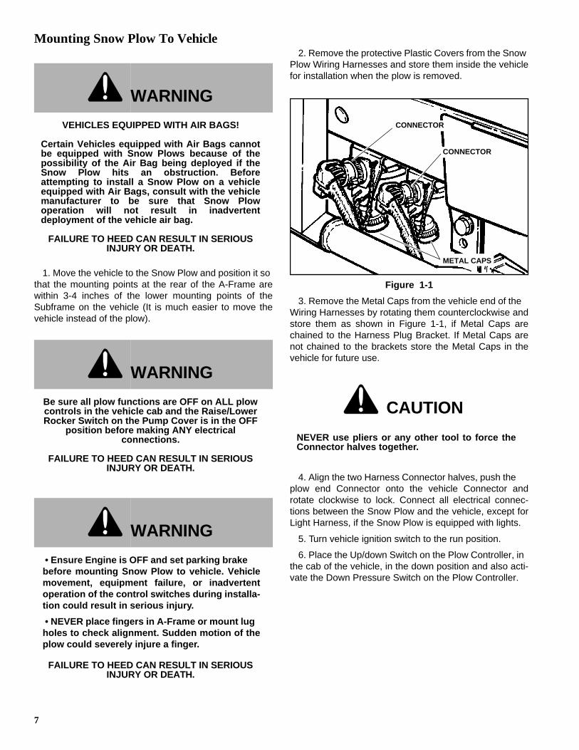
2. Remove the protective Plastic Covers from the Snow Plow Wiring Harnesses and store them inside the vehiclefor installation when the plow is removed.
Figure 1-1
3. Remove the Metal Caps from the vehicle end of the Wiring Harnesses by rotating them counterclockwise andstore them as shown in Figure 1-1, if Metal Caps arechained to the Harness Plug Bracket. If Metal Caps arenot chained to the brackets store the Metal Caps in thevehicle for future use.
4. Align the two Harness Connector halves, push the plow end Connector onto the vehicle Connector androtate clockwise to lock. Connect all electrical connec-tions between the Snow Plow and the vehicle, except forLight Harness, if the Snow Plow is equipped with lights.
5. Turn vehicle ignition switch to the run position.
6. Place the Up/down Switch on the Plow Controller, in the cab of the vehicle, in the down position and also acti-vate the Down Pressure Switch on the Plow Controller.
WARNING
VEHICLES EQUIPPED WITH AIR BAGS!
Certain Vehicles equipped with Air Bags cannotbe equipped with Snow Plows because of thepossibility of the Air Bag being deployed if theSnow Plow hits an obstruction. Beforeattempting to install a Snow Plow on a vehicleequipped with Air Bags, consult with the vehiclemanufacturer to be sure that Snow Plowoperation will not result in inadvertentdeployment of the vehicle air bag.
FAILURE TO HEED CAN RESULT IN SERIOUS INJURY OR DEATH.
WARNING
Be sure all plow functions are OFF on ALL plow controls in the vehicle cab and the Raise/Lower Rocker Switch on the Pump Cover is in the OFF
position before making ANY electrical connections.
FAILURE TO HEED CAN RESULT IN SERIOUS INJURY OR DEATH.
WARNING
• Ensure Engine is OFF and set parking brake before mounting Snow Plow to vehicle. Vehiclemovement, equipment failure, or inadvertentoperation of the control switches during installa-tion could result in serious injury.
• NEVER place fingers in A-Frame or mount lug holes to check alignment. Sudden motion of theplow could severely injure a finger.
FAILURE TO HEED CAN RESULT IN SERIOUS INJURY OR DEATH.
CAUTION
NEVER use pliers or any other tool to force theConnector halves together.
METAL CAPS
CONNECTOR
CONNECTOR

8
7. Raise the rear of the A-Frame (using the RockerSwitch on the pump cover) to ensure that the A-Frame ishigher than the Subframe mounting points. The plow canthen be manually moved into position for connecting thelower Hitch Pins. Move the plow manually by graspingone end of the blade and moving one side and then theother side. Again, if the plow is more than 3-4 inches fromproper alignment, move the vehicle - it’s easier. Butremember to disconnect the electrical connectionsBEFORE backing away from the plow to avoid stretchingand damaging the electrical Wiring Harness. (See Figure1-2)
Figure 1-2
WARNING
When using the raise/lower Rocker Switch on thePump Cover to raise or lower the Plow A-Framebe especially careful of the movement of thelight bar, if equipped, which occurs duringraising and lowering of the A-Frame on theJackstand.
FAILURE TO HEED CAN RESULT IN SERIOUS INJURY OR DEATH.
CAUTION
NEVER move vehicle while plow is connectedelectrically.
ROCKER SWITCH
JACKSTAND
SPRING PIN
8. Lower the A-Frame into alignment with the lowerHitch Pin mounting holes of the vehicle Subframe andinstall the two lower Hitch Pins. Secure with Lynch Pins.(See Figure 1-4)
Figure 1-3
NOTE: If the plow and vehicle are not level with each other, install one lower Hitch Pin and then, using the Rocker Switch on the pump cover, (See Figure 1-3) adjust the A-Frame height to allow installation of the second lower Hitch Pin.
9. After the lower Hitch Pins and Lynch Pins have beeninstalled, place the Rocker Switch in the lower position toallow the Jackstand to be raised off the ground. Thenrotate the Jackstand forward and upward and latch it inthe transport storage position with the Spring Pin. (SeeFigure 1-2)
IMPORTANT: The end of the Spring Pin fits into ashort tube on the side of the Bellcrank assembly. Ifthe Pin is not retained in this tube, the Jackstandmay become loose and fall down during plowing ortransport.
10. Raise the Lift Link and Light Bar manually to align theupper Hitch Pin mounting lugs and slide the upper HitchPin into place. Install the Lynch Pin to retain the HitchPin. (See Figure 1-4)
LYNCH PIN
HITCH PIN

9
Figure 1-4
11. Connect the Snow Plow Light Harness to the vehiclelight harness.
12. Move the Rocker Switch on the Pump Cover to the“lower” position to allow normal Snow Plow operation.
Installing The Cylinder Lock Clamp
1. Raise the plow to the full UP position and fully extendLeft Wing.
2. Turn ignition switch OFF and apply the emergencybrake.
3. Remove the Pins from the Cylinder Lock Clamp andspread it apart.
4. Position the Cylinder Lock Clamp around theexposed (chrome) portion of the Lift Cylinder and installthe Pins. Install the Hairpin Cotters Into the Pins. (See Figure 1-5)
Figure 1-5
Removing Snow Plow From VehicleChoose a location for plow storage which will allow theplow to be removed from the vehicle and not moved afterremoval. Also, choose a location which will not allow thestand to sink into the ground during storage.
1. Drive vehicle to the desired Snow Plow storage area.It is recommended that the plow be stored in a dryprotected area.
NOTE: Plow should be thoroughly cleaned of all grime and road salt before it is put into storage
2. Retract wings to a "V" position and lower the plow tothe ground.
3. Put vehicle in park and turn off engine.
WARNING
• Always install the Cylinder Lock Clamp when the plow blade is raised and the operator is notengaged in plowing operations. Equipment fail-ure or inadvertent operation of the controlswitches while driving could allow the plowblade to fall, resulting in serious injury.
• Ensure Engine is OFF and set parking brakebefore installing the Cylinder Lock Clamp. Vehi-cle movement, equipment failure, or inadvertentoperation of the control switches during installa-tion could allow the plow blade to fall, resultingin serious injury.
FAILURE TO HEED CAN RESULT IN SERIOUS INJURY OR DEATH.
HITCH PIN
LYNCH PIN
WARNING
• Ensure engine is OFF and parking brake is setbefore removing Snow Plow from vehicle. Vehi-cle movement, equipment failure, or inadvertentoperation of the control switches during removalcould result in serious injury.
• Ensure all personnel are clear of the area sur-rounding the blade storage location beforeangling or lowering the blade to prevent seriousinjury.
FAILURE TO HEED CAN RESULT IN SERIOUS INJURY OR DEATH.
HAIRPIN COTTERS
CYLINDER CLAMP
10
4. Turn vehicle ignition switch to run position only.
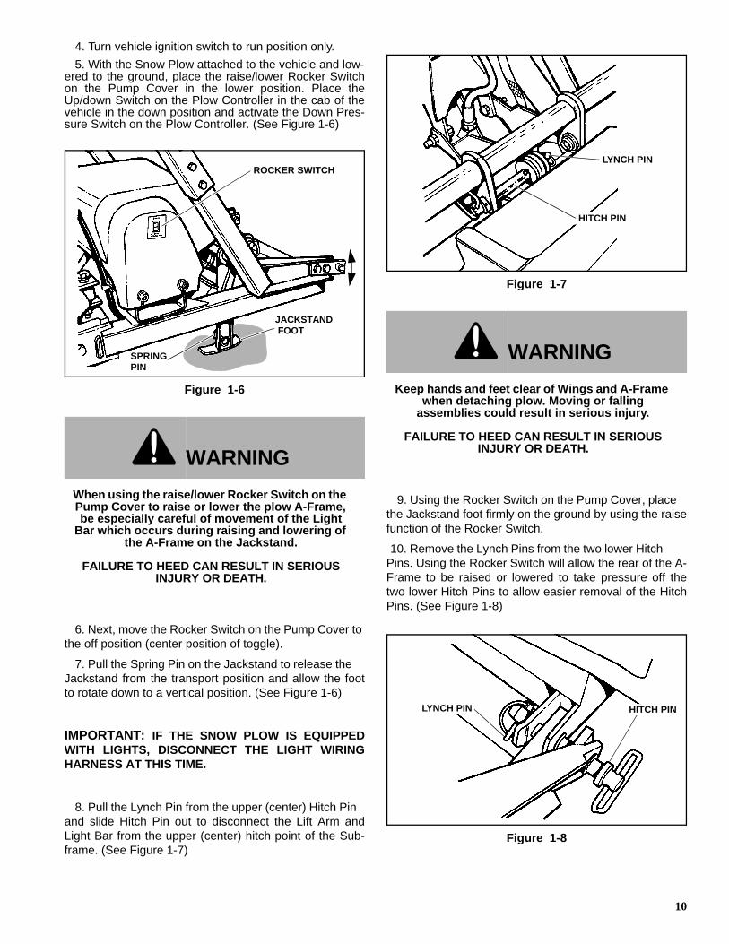
5. With the Snow Plow attached to the vehicle and low-ered to the ground, place the raise/lower Rocker Switchon the Pump Cover in the lower position. Place theUp/down Switch on the Plow Controller in the cab of thevehicle in the down position and activate the Down Pres-sure Switch on the Plow Controller. (See Figure 1-6)
Figure 1-6
6. Next, move the Rocker Switch on the Pump Cover tothe off position (center position of toggle).
7. Pull the Spring Pin on the Jackstand to release theJackstand from the transport position and allow the footto rotate down to a vertical position. (See Figure 1-6)
IMPORTANT: IF THE SNOW PLOW IS EQUIPPEDWITH LIGHTS, DISCONNECT THE LIGHT WIRINGHARNESS AT THIS TIME.
8. Pull the Lynch Pin from the upper (center) Hitch Pinand slide Hitch Pin out to disconnect the Lift Arm andLight Bar from the upper (center) hitch point of the Sub-frame. (See Figure 1-7)
Figure 1-7
9. Using the Rocker Switch on the Pump Cover, placethe Jackstand foot firmly on the ground by using the raisefunction of the Rocker Switch.
10. Remove the Lynch Pins from the two lower HitchPins. Using the Rocker Switch will allow the rear of the A-Frame to be raised or lowered to take pressure off thetwo lower Hitch Pins to allow easier removal of the HitchPins. (See Figure 1-8)
Figure 1-8
WARNING
When using the raise/lower Rocker Switch on the Pump Cover to raise or lower the plow A-Frame, be especially careful of movement of the Light
Bar which occurs during raising and lowering of the A-Frame on the Jackstand.
FAILURE TO HEED CAN RESULT IN SERIOUS INJURY OR DEATH.
ROCKER SWITCH
JACKSTAND FOOT
SPRING PIN
WARNING
Keep hands and feet clear of Wings and A-Frame when detaching plow. Moving or falling
assemblies could result in serious injury.
FAILURE TO HEED CAN RESULT IN SERIOUS INJURY OR DEATH.
LYNCH PIN
HITCH PIN
LYNCH PIN HITCH PIN

11
11. After the lower Hitch Pins are removed, raise the rearof the A-frame (using the raise function of the RockerSwitch) to allow the A-Frame to clear the lower mountingpoints of the Subframe.
12. After the plow is positioned satisfactorily for storage,disconnect the electrical connections between the SnowPlow and vehicle.
13. Rotate the outer collars of the electrical quick discon-nect plugs counterclockwise to unlock, then pull SnowPlow end of plugs out of connectors.
Figure 1-9
NOTE: Place protective Metal Caps on the vehicle half of the quick disconnects and place the plastic storage Covers (normally kept in the vehicle) on the Snow Plow half of the wiring harness connectors. Tuck the Snow Plow end of the plugs in an area of the Snow Plow where they are not exposed to potential damage such as crushing or corrosion.
14. After all mechanical and electrical connections havebeen disconnected, back the vehicle away from the SnowPlow.
Plow Storage1. If the plow will not be stored on a firm surface (i.e.
concrete or asphalt), place a board or piece of plywood,etc. under the Jackstand to prevent the Jackstand footfrom sinking into the ground.
2. Place a support under the rear of the A-frame duringstorage to prevent any inadvertent movement of the plowfrom tipping the stand allowing the rear of the A-frame tofall.
3. To avoid corrosion during storage, coat the exposed(chrome) portion of the lift and angle cylinders with a lightgrease.
4. Grease all pivot points.
5. Top off Hydraulic reservoir to minimize trapped air.
6. Make sure that protective Caps are on all electricalconnections. A small amount of dielectric grease may beused to insure a moisture proof seal on the Caps.
7. Check and replace any worn and/or damaged com-ponent, such as cutting edges or deflectors. Performingpreventative maintenance tasks in the spring when plowis stored will ensure that you will be ready to plow in thefall.
CAUTION
Never use pliers or any other tool to separate thewiring harness connector halves.
COVER
Metal Caps
CONNECTOR
CONNECTOR

12
IntroductionWhenever service is necessary, your local dealer knowsyour plow best and is interested in your completesatisfaction. Return your Snow Plow to your local dealerfor Maintenance service or any other assistance you mayrequire. If you are unable to do so, this Trouble ShootingGuide should help you determine the problem. Also, thereare Repair Manuals available from your local dealer.However, before attempting the servicing of your plow,you should possess good mechanical abilities and a totalunderstanding of the mechanism.
PLEASE: Before calling parts and service personnel becertain that:
1. You have read this guide carefully and are certainthat all of the suggestions pertaining to your problemhave been attempted.
2. You have the following information available.
A. Date Snow Plow was originally installed.B. Power Pack Model Number.C. Power Pack Serial Number.D. Controller Serial Number.E. Blade Model Number.F. Blade Serial Numbers.G. Pump Serial Number.
This information should be recorded on page 2 of thisOwners Manual.
Trouble Shooting-Quick Reference General
1. Check to see that vehicle ignition switch is “on” or in“run” position.
2. Check, and replace if necessary, accessory fuse invehicle fuse panel.
3. Check all wiring to be sure that battery terminals areclean and connections to battery, circuit breaker, sole-noid, switches and all connectors on plow harness areclean and tight.
4. Check oil level in hydraulic system reservoir.
5. Check for external leakage at cylinders, hoses andpower unit.
6. Check the voltage at the coils which operate the sole-noid valves to be sure that the voltage at the coils is aminimum of 9-1/2 volts DC.
CAUTION
First read all warning instruction, the safetymessages, and directions before attempting anyadjustments or repairs to your unit!
TROUBLE SHOOTING GUIDE

13
TROUBLESHOOTING
PROBLEM PROBABLE CAUSE CORRECTIVE ACTION
Plow will not lift (Motor runs) Hydraulic fluid level low See Maintenance Section
Defective Raise/Lower Switch Refer to Dealer
Improper main pressure relief valve pressure setting, debris
causing valve to stick
Refer to Dealer
Breather cap plugged See Maintenance Section
Faulty raise/lower solenoid coil Refer to Dealer
Raise/lower solenoid valve stuck in lower position
Refer to Dealer
Raise/lower cylinder frozen or binding
Refer to Dealer
Defective or sticking Down Pressure Solenoid Valve
Refer to Dealer
Diode in vehicle harness defective or missing
Refer to Dealer
Pick-up tube filter plugged See Maintenance Section
Pick-up tube is not submerged in fluid
See Maintenance Section
Machine failure Refer to Dealer
Motor continues to run and will not shut-off
Motor Solenoid defective Refer to Dealer
Machine defective Refer to Dealer
Plow lifts slowly Hydraulic fluid level low See Maintenance Section
Breather cap plugged See Maintenance Section
Improper main relief pressure setting, debris causing valve to
stick
Refer to Dealer
Pick-up tube filter plugged See Maintenance Section
Improper oil viscosity for outside air temperature, unit not at normal
operating temperature
See Maintenance Section
Defective Lift Cylinder Refer to Dealer
Machine failure Refer to Dealer

14
Fluid leaking at Pump Assembly
Hydraulic fittings not torqued properly (too tight, too loose)
Refer to Dealer
O-Rings between valve block and endhead are worn or not seating
properly
Refer to Dealer
O-Rings between endhead and reservoir worn or not seating
properly
Refer to Dealer
Reservoir over-full See Maintenance Section
O-Ring on solenoids or pressure switches defective
Refer to Dealer
Endhead cracked Refer to Dealer
Valve body cracked Refer to Dealer
Unit lifts but does not hold - first action
Dirt in check valve or lower solenoid valve
Cycle raise and lower system to flush debris
Lower solenoid valve sticking Cycle raise and lower system to un-stick valve
Unit lifts but does not hold - second action
Dirt or debris in check valve Refer to Dealer
Check valve spring broken Refer to Dealer
Raise/lower solenoid valve sticking
Refer to Dealer
Seals O-Ring(s) on raise/lower solenoid valve or down pressure
solenoid valve damaged
Refer to Dealer
Current available at raise/lower solenoid without switch function
Refer to Dealer
Raise /lower ram defective allowing movement in one
direction only
Refer to Dealer
Machine failure Refer to Dealer
Unit will not lower
NOTE: Only in Non- down pressure mode
Plugged breather cap See Maintenance Section
Low or no current available at raise/lower Solenoid
Refer to Dealer
Raise/lower solenoid valve sticking
Refer to Dealer
Raise/lower solenoid coil defective
Refer to Dealer
Raise lower ram defective allowing movement in one
direction only
Refer to Dealer
Machine failure Refer to Dealer
TROUBLESHOOTING
PROBLEM PROBABLE CAUSE CORRECTIVE ACTION

15
Unit will not lower
NOTE: In down pressure mode only
See all above conditions Refer to Dealer
Raise lower ram defective allowing movement in one
direction only
Refer to Dealer
Defective down pressure switch in Control Box
Refer to Dealer
Defective down pressure solenoid Refer to Dealer
Machine failure Refer to Dealer
Motor will not run Motor brushes worn/commutator worn or dirty
Refer to Dealer
Seal between motor and pump defective allowing oil to enter
motor housing
Refer to Dealer
Defective Start Solenoid Refer to Dealer
Motor seized Refer to Dealer
Machine failure Refer to Dealer
Blade wing moves in one direction only
Solenoid valve sticking or defective
Refer to Dealer
Crossover relief valve defective or sticking
Refer to Dealer
Low or no current available at extend or retract solenoid valve
Refer to Dealer
Crossover relief valve pressure setting too low
Refer to Dealer
Angle cylinder defective allowing movement in one direction only
Refer to Dealer
Machine failure Refer to Dealer
Blade wing will not move Hydraulic fluid level low See Maintenance Section
Crossover pressure relief valve setting too low
Refer to Dealer
Solenoid valve sticking or defective
Refer to Dealer
Low or no current available at solenoid valve
Refer to Dealer
Wing cylinder binding or frozen Refer to Dealer
Pick up tube not submerged in fluid
See Maintenance Section
Machine failure Refer to Dealer
TROUBLESHOOTING
PROBLEM PROBABLE CAUSE CORRECTIVE ACTION

16
Blade wing will not move, but plow raises when trying to
move wings
Main power solenoid defective or sticking
Refer to Dealer
Low or no current available at main power solenoid valve
Refer to Dealer
Blade wing moves very slowly Hydraulic fluid level low See Maintenance Section
Crossover Relief Valve defective or sticking
Refer to Dealer
Crossover Relief Valve pressure setting to low
Refer to Dealer
Improper oil viscosity for outside air temperature, unit not at normal
operating temperature
See Maintenance Section
Defective Wing Cylinder Refer to Dealer
Dirt or debris in Solenoid Valve Refer to Dealer
Blade wings will not hold position (fold rearward)
Defective or dirt/debris in Wing Relief Valve
Refer to Dealer
Defective or sticking Solenoid Valve
Refer to Dealer
Dirt or debris in Solenoid Valve Refer to Dealer
Defective Wing Cylinder Refer to Dealer
TROUBLESHOOTING
PROBLEM PROBABLE CAUSE CORRECTIVE ACTION
17
General• Before operating, perform a thorough visual
inspection of the equipment. Look for fluid leaks,cracked, bent or broken components, loose nuts,bolts or attachments and proper fluid levels.
• A clean hydraulic system is essential to long pump life and proper performance.
• When adding oil to the reservoir, wipe the areaaround the filler port clean before removing thebreather cap. Use clean oil and a clean funnel, (DONOT use a cloth or rag to strain the oil).
IMPORTANT: Hydraulic unit comes from factorycharged with Type 5606. If additional oil is added itmust be compatible with Type 5606. If another type ofoil has been used in the system the same type of oilmust be used for topping off system. Improperhydraulic fluid can cause operating problems in coldweather.
• The operational environment for Snow Plows is anextremely harsh and corrosive one.
• Ensure all electrical connections are clean andtight.
• To prevent rust from forming, clean and repaintexposed metal surfaces.
• NEVER operate the equipment with the protectivecovers or guards removed.
Periodic InspectionAfter approximately every 20 hours of operation performthe following inspections procedures:
1. Inspect the plow assembly including the Subframeassembly for any damage or excessive wear. Alsoinspect all fasteners to insure that they are properlytightened. If any fasteners are loose re-tighten to theproper torque (Refer to the Torque Specification chart inthis manual). Also carefully inspect adjacent area fordamage or wear as well as carefully inspecting alladjacent fasteners for proper torque.
2. Apply a small amount of light oil to the Hitch Pins andpivots, to Pivot Pins between the Center Blade Assemblyand the Intermediate Pivot Assembly, between Lift andSwing Cylinder pivot Pins and the Lift Linkage Pivots.
3. Lubricate the Wing Pivot Shafts with a good qualityHP Lithium based grease.
NOTE: For extremely cold weather plowing, continuous sub Zero operation, an alternative is to remove the grease fittings and fill the grease cavity with SAE 140 Gear Oil, and then replace the grease fitting.
Special Fasteners Torques and Requirements
IMPORTANT: Incorrectly securing fasteners mayresult in incorrect operation, excessive wear, andearly failure of plow components. It may also voidyour warranty.
• ALWAYS check to make sure you are using thecorrect Torque specification for the fastener you areusing.
• DO NOT use any lubricants on the threads of anyfastener unless specifically called for in theassembly or maintenance story for that component.
• NEVER use liquid locking materials, such asLocktite™ or Threadmaker™, on any fastenersunless specifically called for in an assembly ormaintenance story for that component.
Standard Fasteners:
The Torque Specifications Chart on page 25 of thismanual should be used as the guide for fastener Torquerequirements for most standard fasteners used on theplow.
Standard fasteners with special Torque requirements willbe noted in assembly or service stories pertaining to thespecific piece of equipment.
Hydraulic Fittings:
Hydraulic fittings with lock nuts should be assembled withat least three full turns of the fitting in the port and then thelock nut should be tightened to 27 lb.-ft.
Wing Cylinder Attaching Fasteners:
Base end and Rod end attachment cap screws are alwaysassembled with the cap screw head UP.
Always use a Nylock nut and only Torque the nut to 25 to30 lb.-ft. DO NOT overtighten these fasteners.Overtightening of wing cylinder attachment fasteners maybind cylinder and cause excessive cylinder wear and/orrestrict wing movement.
Bellcrank Assembly to Lift Arm Assembly Fasteners:
Apply Locktite 242™ (Blue) to the threads of the capscrews and tighten the jam nut to 70 lb.-ft. Then place thelock nut on the cap screw and tighten to 70 lb.-ft.
MAINTENANCE

18
Pivot Frame Assembly:
Install the 1" Slotted Nut on the threaded end of theSpecial Screw and tighten finger tight. Then tighten thenut another 2/3 to 1 full turn and line up a slot in the nutwith the cross hole in the Special Screw. Install the3/16"x2" Cotter Pin in the Special Screw and spread theends of the Cotter Pin.
Hydraulic CylindersTo avoid corrosion during storage, coat the exposed(chrome) portion of the lift and angle cylinders with a lightgrease.
Electrical Quick Disconnect PlugsInstall protective Caps on quick disconnect ends toprevent corrosion from forming on terminal ends duringstorage or when plow is disconnected from vehicle.
Service IntervalsIt is recommended to change the fluid in the hydraulicsystem once a season.
Fluid Requirements
IMPORTANT: Hydraulic unit comes from factorycharged with Type 5606. If additional oil is added itmust be compatible with Type 5606.
NOTE: when Type 5606 is not available Exxon UNIVIS J13 or equivalent may be used.
Changing Oil and Cleaning Filter Screen
NOTE: We recommend cleaning the filter screen and magnet at every oil change, this will help ensure maximum life and maximum performance from the pump assembly.
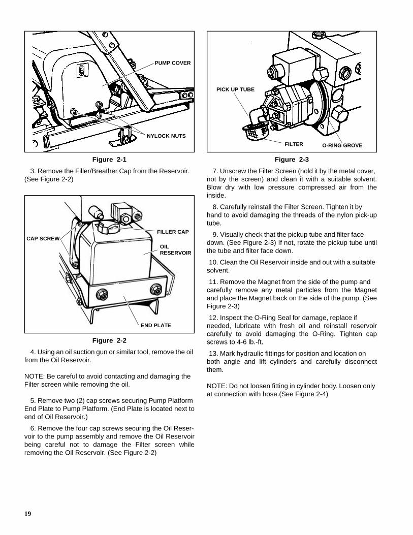
1. Lower plow assembly to ground, put vehicle in parkand turn off engine.
2. Loosen four Nylock Nuts attaching Pump Cover toframe. Remove the pump cover taking care not to discon-nect wires to Rocker Switch mounted in Pump Cover.
CAUTION
• Using the proper oil increases the life expect-ancy of the most critical part of your plow; theHydraulic power unit.
• Failure to use the proper oil can cause extensive damage to the power unit, seals and hydraulicrams.
• Improper oil can cause operating problems and poor performance in cold weather.
CAUTION
Using the proper oil increases the lifeexpectancy of the most critical part of your unit;the Hydraulic power unit.
WARNING
• Allow the system to cool down before drainingoil or handling system components. Seriousburns can result from contact with hot oil.
• Never disconnect any hydraulic line or fittingwith the unit in the raised position. Always lowerthe unit and relieve pressure before removingany lines or caps.
FAILURE TO HEED CAN RESULT IN SERIOUS INJURY OR DEATH.
WARNING
Ensure Engine is OFF and set parking brake before working on Plow. Vehicle movement,
equipment failure or inadvertent operation of the control switches during maintenance could
result in serious injury
FAILURE TO HEED CAN RESULT IN SERIOUS INJURY OR DEATH.
19
Figure 2-1
3. Remove the Filler/Breather Cap from the Reservoir.(See Figure 2-2)
Figure 2-2
4. Using an oil suction gun or similar tool, remove the oilfrom the Oil Reservoir.
NOTE: Be careful to avoid contacting and damaging the Filter screen while removing the oil.
5. Remove two (2) cap screws securing Pump PlatformEnd Plate to Pump Platform. (End Plate is located next toend of Oil Reservoir.)
6. Remove the four cap screws securing the Oil Reser-voir to the pump assembly and remove the Oil Reservoirbeing careful not to damage the Filter screen whileremoving the Oil Reservoir. (See Figure 2-2)
Figure 2-3
7. Unscrew the Filter Screen (hold it by the metal cover,not by the screen) and clean it with a suitable solvent.Blow dry with low pressure compressed air from theinside.
8. Carefully reinstall the Filter Screen. Tighten it byhand to avoid damaging the threads of the nylon pick-uptube.
9. Visually check that the pickup tube and filter facedown. (See Figure 2-3) If not, rotate the pickup tube untilthe tube and filter face down.
10. Clean the Oil Reservoir inside and out with a suitablesolvent.
11. Remove the Magnet from the side of the pump andcarefully remove any metal particles from the Magnetand place the Magnet back on the side of the pump. (SeeFigure 2-3)
12. Inspect the O-Ring Seal for damage, replace ifneeded, lubricate with fresh oil and reinstall reservoircarefully to avoid damaging the O-Ring. Tighten capscrews to 4-6 lb.-ft.
13. Mark hydraulic fittings for position and location onboth angle and lift cylinders and carefully disconnectthem.
NOTE: Do not loosen fitting in cylinder body. Loosen only at connection with hose.(See Figure 2-4)
NYLOCK NUTS
PUMP COVER
FILLER CAPCAP SCREW
OIL RESERVOIR
END PLATE
PICK UP TUBE
O-RING GROVEFILTER

20
Figure 2-4
14. Manually work the two Angle and Lift Cylindersthrough their entire range of motion in order to drain thefluid remaining in the Cylinders.
15. Reconnect hydraulic fittings in their correct positionand Torque to 20-25 lb.-ft. If unit utilizes O-Ring and jamnut type connectors tighten jam nut to 15-20 lb.-ft.
16. Fill the hydraulic Oil Reservoir until the fluid level reg-isters full on Oil Level Mark on Oil Reservoir.
NOTE: Vehicle must be parked on level ground, Plow must be in the lowered position, and Wings must be folded rearward ("V") in order to properly check the oil level. Checking oil level with plow elevated or with Wings straight or folded forward will give wrong reading.
17. Refer to plow operation instructions and operate theplow to purge all air from the hydraulic system.
18. Replenish the fluid in the reservoir until the fluid levelregisters full on Oil Level Mark on Oil Reservoir.
19. Operate system and check for leaks, repair or tightenas necessary.
Disk Shoe Adjustment
IMPORTANT: This Plow is equipped with three (3)Disk Shoes. Two Disk Shoes are located at theoutboard end of each Wing. The third Disk Shoe islocated under the Trip Springs on the Center PlowAssembly. All three Disk Shoes must be adjustedequally.
IMPORTANT: To ensure the best function of thisSnow plow, it is a requirement that all three DiskShoes be used at ALL times.
1. Drive the vehicle, with Snow Plow mounted, onto asmooth, level surface. Park the vehicle, move the PlowWings until the Wings are straight out on each side andlower the Plow to the ground.
2. Turn ignition switch OFF and apply the emergencybrake.
3. Inspect both Float Limiter Screws and be sure thatthe hex head of the screws are not contacting the wearplate underneath the hex head of the screw. If necessary,adjust each screw upward so that the screw head is notcontacting the wear plate when the pivot tubes are verti-cal.
NOTE: After Disk Shoe Adjustment is completed, the Float Limiter Adjustment must be made. See “Float Limiter Adjustment on page 22
4. Place a level against the front of the Wing PivotTubes and pull or push the top of the Center Section untilthe level indicates that the Pivot Tubes are vertical (Nottipped either forward or rearward.
5. Determine whether the Center Disk Shoe or the Cen-ter Wearstrip is off the ground and measure the amountthat it is off the ground. (See Figure 2-5)
CAUTION
Do Not use Teflon® tape or Pipe Dope onhydraulic fittings. These can dislodge and jamvalves in the hydraulic system.
LOOSEN HERE ONLY

21
Figure 2-5
NOTE: Gap may be measured by sliding shims or washers between the ground and/or the Center Disk Shoe or the Center Wearstrip, then measuring the shim/washer stack. The Center Disk Shoe will need to be adjusted until the Disk Shoe and Center Wearstrip both contact the ground at the same time.
• If the Center Disk Shoe was off the ground - Washersmust be ADDED below the Disk Shoe Mounting Tube.
• If the Center Wearstrip was off the ground - Washersmust be REMOVED from below the Disk Shoe Mount-ing Tube.
IMPORTANT: If Washers must be added, add oneWasher LESS than the amount the Disk Shoe was offthe ground. If Washers must be removed, remove oneWasher MORE than the amount the Wearstrip was offthe ground.
6. Raise Plow and place suitable blocking under thePlow to allow at least eight inches (8") of clearance fromthe bottom of the Center Disk Shoe to the ground.
7. Lower Plow onto blocking.
8. Adjust Center Disk Shoe assembly by removing theDisk Shoe Mounting Pin and adding or subtracting Wash-ers on the top or bottom of the Disk Shoe MountingBracket as required according to measurements taken instep #4.
9. After the Center Disk Shoe position is properlyadjusted, place washers on the Disk Shoe Stem - abovethe Disk Shoe Mounting Bracket, and below the Retain-ing Pin - to remove all up and down movement of the DiskShoe in the Bracket. Failure to do this will result in exces-sive wear of the holes in the Disk Shoe Mounting Bracketand will also result in bending the Disk Shoe Stem.
10. After the Center Disk Shoe adjustment is completed,lower the Plow to the ground. If this Disk Shoe adjust-ment is correct, the Center Disk Shoe and the CenterWearstrip will both be on the ground and the Wing Tubeswill be vertical (Recheck the Wing Tubes with a level). IfWing Tubes are not vertical, repeat steps #3 to #9 untilWing Tubes are vertical.
NOTE: If assembling and mounting a Snow Plow for the first time, the adjustment of the Center Disk Shoe can be done with just the Center Section Mounted on the vehicle, prior to assembling the Wings onto the Center Section of the Plow.
11. With each Wing extended straight out to each side,measure the amount the Wing Shoes are off the ground,or if they are on the ground, measure the amount that theWearstrip is off the ground (measured in front of the DiskShoe Bracket).
12. Raise Plow and place suitable blocking under thePlow to allow at least six inches (6") of clearance from thebottom of the Wing Disk Shoes to the ground.
13. Lower Plow onto blocking.
LEVEL
WASHERS
CENTER
EQUAL DISTANCE
CENTERWEARSTRIP
DISK SHOE
WARNING
Keep hands and feet clear of Wings and Center Section when setting blocking and lowering
Plow. Moving or falling assemblies could result in serious injury.
FAILURE TO HEED CAN RESULT IN SERIOUS INJURY OR DEATH.

22
14. Adjust each Disk Shoe assembly by removing DiskShoe mounting Pin and adding or subtracting Washerson the top or bottom of the Disk Shoe Mounting Bracketas required according to measurements taken in step#11 (See Figure 2-6)
Figure 2-6
15. After the Disk Shoe position is properly adjusted,place washers on the Disk Shoe Stem - above the DiskShoe Mounting Bracket, and below the Retaining Pin - toremove all up and down movement of the Disk Shoe inthe Bracket. Failure to do this will result in excessive wearof the holes in the Disk Shoe Mounting Bracket and willalso result in bending the stem of the Disk Shoe.
16. After the Wing Disk Shoe adjustment is complete,lower the Plow to the ground. If this Disk Shoe adjust-ment is correct, the Shoes and the Wearstrips will all beon the ground at the same time, if not, repeat steps #11to #15.
17. Move the Wings forward and rearward. If the WingWearstrips and the Center Wearstrips are not on theground at all times recheck the position of the Wing PivotTubes. The Tubes must be Vertical, if they are not verti-cal, the Center Disk Shoe will need to be adjusted.
Float Limiter Adjustment
IMPORTANT: The Disk Shoes must be properlyadjusted prior to adjusting the Float Limiter. If theshoes are not properly adjusted, the Float LimiterAdjustment cannot be properly made.
1. With the vehicle and Snow Plow on a smooth, levelsurface move the Wings forward into the “Scoop” positionand lower the Plow to the ground.
Figure 2-7
2. Loosen the 5/8" Jam Nut on the top of the float limiterAdjusting Screw.
3. Using the screwdriver slot in the top of the Float Lim-iter Adjusting Screw, turn the Adjusting Screw down untilthe hex head of the Adjusting Screw touches the surfaceof the replaceable Wear Plate.
4. Turn the Adjusting Screw up two turns to provide agap between the wear plate and the head of the Adjust-ing Screw for proper float allowance.
5. While holding the Adjusting Screw driver slot, to pre-vent turning of the Adjusting Screw, tighten the 5/8” JamNut to lock the Adjusting Screw and prevent turning of theAdjusting Screw during operation.
WARNING
Keep hands and feet clear of Wings and Center Section when setting blocking and lowering
Plow. Moving or falling assemblies could result in serious injury.
FAILURE TO HEED CAN RESULT IN SERIOUS INJURY OR DEATH.
WASHERS
PIN
JAM NUT
ADJUSTING SCREW
REPLACEABLEWEAR PLATE

23
Pivot Assembly Pivot Screws
Figure 2-8
1. The hex head of the Pivot Screw must be seatedwithin the hex opening of the Retainer Plate.
Figure 2-9
2. Install the special 1/4" Thick Washer on the threadedend of the Pivot Screw and install the 1" Slotted Nut fin-ger tight. Then tighten the nut an additional 2/3 to 1 fullturn and line up a slot in the nut with the cross hole in thePivot Screw. Install a 3/16"x2" Cotter Pin through the slotin the Slotted Nut and the cross hole in the Pivot Screwand spread both Cotter Pin ends.
Cutting Edge
NOTE: Cutting Edge must be replaced when it is worn to the bottom edge of the frame.
1. Raise the Plow to the full UP position.
2. Place suitable blocking under A-Frame of plow toallow at least 6" of clearance from the Blade to theground.
IMPORTANT: Make sure to position blocking awayfrom Cutting Edge so that when plow is lowered ontoblocking Cutting Edges do not rest on blocking.
3. Lower Plow onto blocking.
4. Remove mounting bolts holding old Center CuttingEdge and Short Inner Wing Cutting Edges to Blade. Dis-card old Cutting Edges and hardware.
IMPORTANT: Do not remove Long Wing CuttingEdges at this time. Short Inner Cutting Edges mustbe installed before removal of Long Wing CuttingEdges.
PIVOT SCREW
RETAINER PLATE
PIVOT SCREW
THICK WASHER
SLOTTED NUT
WARNING
Keep hands and feet clear of Wings and A-Frame when setting blocking and lowering blade.
Moving or falling assemblies could result in serious injury.
FAILURE TO HEED CAN RESULT IN SERIOUS INJURY OR DEATH.
CAUTION
Cutting Edges may be sharp. Always weargloves and handle Cutting Edges with care toavoid injury.

24
Figure 2-10
5. Install new Short Inner Cutting Edges using newhardware.
NOTE: The Blade Skin must be retained prior to removing the Long Wing Cutting Edges. This can be accomplished by using a 6" C-Clamp located at the center of the curved portion of the Blade Skin at the outer end of the Wing. The Short Inner Cutting Edges will retain the inner end of the Blade Skin.
6. Remove the mounting bolts holding the old LongWing Cutting Edges to the Blade Wings. Discard old Cut-ting Edges and hardware.
7. Install new Long Wing Cutting Edges using new hard-ware.
8. Install new Center Cutting Edge and secure with newMounting Strip and new hardware. Torque the three Cen-ter Cutting Edge fasteners to 50 lb.-ft.
Trip Spring Adjustment
NOTE: The Trip Springs are factory installed and adjusted, but adjustment should be checked during Plow Set-Up and installation.
The Springs are properly adjusted when the coils begin toseparate.
If readjustment is required:
1. Raise the plow to transport position and placeblocking under the plow to prevent the plow frominadvertently dropping.
2. Turn off the vehicle ignition, apply the parking brakeand remove the vehicle ignition key.
3. Check to make sure that the Spring is installed asillustrated with open end of top loop facing vehicle. (SeeFigure 2-11)
4. Using a 15/16" socket wrench through the holes inthe Bottom Plate of the Main Frame, loosen the two (2)5/8" Nuts on the Trip Spring Eyebolts. (See Figure 2-11)
5. After the two lower nuts have been loosened, the twoupper nuts can be rotated on the eye bolts to allow theTrip Springs to be shortened or lengthened.
6. While holding the two upper nuts, re-tighten the twolower nuts and then re-check the spring adjustment.
NOTE: Springs are properly adjusted when two or more coils allow a 0.010" feeler gauge to just pass between the separated coils. (A 3 x 5 post card is approximately the same thickness.)
Figure 2-11
CENTER CUTTING EDGE
SHORT INNER WING
SHORT INNER WING CUTTING EDGE
CUTTING EDGE
MOUNTING STRIP
CAUTION
• Do not overtighten springs. If more than 0.015"(1/64") gap appears between coil with plow atrest damage could occur to equipment duringplowing.
• Spring must be installed with open end of toploop facing vehicle. Bottom loop position willvary.
0.015 (1/64") GAP
INSTALL WITH OPEN END OF LOOP FACING VEHICLE
JAM NUTS
MAXIMUM

25
TORQUE SPECIFICATIONS
DO NOT use these values if a different torque value or tightening procedure is given for a specific application.
Fasteners should be replaced with the same or higher grade. If higher grade fasteners are used, these should only be tightened to the strength of the original. a "Lubricated" means coated with a lubricant such as engine oil, or fasteners with phosphate and oil coatings. b "Dry" means plain or zinc plated without any lubrication
* Values with asterisk are in lb-in.
Grade 1 Grade 2 Grade 5, 5.1 or 5.2 Grade 8 or 8.2
Lubricateda Dryb Lubricateda Dryb Lubricateda Dryb Lubricateda Dryb
SIZE lb-ft lb-ft lb-ft lb-ft lb-ft lb-ft lb-ft lb-ft
8-32 14* 19* 22* 30* 31* 42*
10-24 21* 27* 32* 43* 45* 60*
1/4 2.8 3.5 4.5 5.5 7 9 10 12.5
5/16 5.5 7 9 11 15 18 21 26
3/8 10 13 16 20 26 33 36 46
7/16 16 20 26 32 41 52 58 75
1/2 25 31 39 50 63 80 90 115
9/16 36 45 56 70 90 115 130 160
5/8 50 62 78 100 125 160 160 225
3/4 87 110 140 175 225 280 310 400
7/8 140 175 140 175 360 450 500 650
1 210 270 210 270 540 675 750 975
1 or 2
2
5 5.1 5.2
5
8 8.2
8
No Marks
No Marks
SAEGradeand NutMarkings
SAEGradeand HeadMarkings

26
HYDRAULIC SCHEMATIC
Port ADirectional ControlCoil/Valve
Port ELeft RetractCoil/Valve Port G
Down PressureCoil/Valve
1 2
M
12 11 9 810 47 5 6 3 13 14 15 16
System Relief2100 PSI
Port 14Orifice0.063 in.
Port HCheckValve
IntakeFilter
NC
Port FLeft ExtendCoil/Valve
Port CRight ExtendCoil/Valve
Port BDownCoil/Valve
Down PressureRelief Valve600-640 PSI
Left Wing CrossoverRelief Valve1500 PSI
Left WingRelief2150 PSI
Right WingRelief2150 PSI
Right Wing CrossoverRelief Valve1500 PSI
Port NPort JPort KPort LPort M
Cyl3CylinderRaise/Lower
Cyl2CylinderRight Angle
Cyl1CylinderLeft Angle
DownPressureSwitch525 PSI
2Yel
13Tan
8Org9Vio
1Blu
6Grn 5Red
10Brn 7Blu/Wht
Port DRight RetractCoil/Valve

27
M
B CA D
ASolenoidMain Power
CSolenoidRight Extend
DSolenoidRight Retract
ESolenoidLeft Retract
FSolenoidLeft Extend
GSolenoidDown Press
S1SwitchJackstand
11B
lu
12Ye
l
11B
lu11
Blu
12Ye
l12
Yel
13Ta
n13
Tan
13Ta
n
5Red
6Grn
7Blk
11B
lu
2Red
0Blk
0Blk
5Red
6Grn
7Blu
/Wht
2Red
0Blk
0Blk
12Ye
l
13Ta
n
Plow Frame Ground
2Yel
3Tan
0Blk
9Vio8Org
10Brn
13Tan14Gra
7Blk6Grn5Red
2Red
10Brn7Blu/Wht
10Brn
11Blu
14Gra
7Blu/Wht
12Yel
M1Motor12VDC C5
PackardConnector
C6DeutschConnector
DOWN
MOM
9Vio
5Red
6Grn
8Org
1Blu
0Blk
0Blk
2Yel
7Blu
/Wht
10B
rn
0Blk0Blk
1Blu
0Blk
2Red
2Red
2Red
R7
R14
11B
lu
12Ye
l
10B
rn
7Blu
/Wht
14G
ra
10B
rn
7Blu
/Wht
11B
lu
12Ye
l
14G
ra
C3BulletConnector1 2 43 65
12Yel
3Tan
1Blu
R S U Y ZXT WV
BSolenoidDown

28
WIRING SCHEMATICRocker Switch Style
234
0Blk
2Red
0Blk2Red
BATTERY
CONTROL BOX
LIGHT
9Vio
8Org
1 2 43 65
0Blk
5Red
1Red
/Blk
6Grn
8Org
9Vio
10B
rn
9Vio
8Org
9Vio
8Org
10B
rn
5Red
9Vio
8Org
10B
rn
5Red
6Grn
7Blu/Wht
5Red
6Grn
7Blk
P3
Pressure Switch
525 PSI
P
10B
rn
1Red
/Blk
6Grn
CAB VEHICLE
2Yel
3Tan
0Blk
9Vio8Org10Brn
13Tan14Gra7Blk6Grn
2Red
2Red
10Brn7Blu/Wht
10Brn
11Blu
14Gra
7Blu/Wht
12Yel
14Gra
10Brn
10B
rn
9Vlt
8Org
C2DeutschConnector
C1PackardConnector
C7BulletConnector
RAISE
LOWER
EXT
RET
EXT
RET
OF
F
ON
GROUND
B CA DC4PackardConnector
2Red
0Blk
13Tan
D1Diode
2Yel3Tan
P6
R3
C9
C8
R1K1SolenoidSwitch
K2CircuitBreaker
R4
R8
R9
R10
R11
R5
R2
R12
R13
0Blk
0Blk
Pnk
Pnk
NOTE: The ground terminal of the lightedDown Pressure Rocker Switch has a brasscolored rivet (Different color than the otherterminals). The black No.’0’ wire must attachto this terminal.
A
A
R S U Y ZXT WV
2Red
R3
5Red
2Red
1
Plow Frame Ground
R15
0Blk
0Blk
0Blk
0Blk
0Blk0Blk
Ignition

29
W1 Wire Harness - Vehicle
C
D A
B
C1Four Terminal Molded Connector
C4Packard Connector
C5Packard Connector
C3Bullet Connector
C7Bullet Connector
W2 Wire Harness - Control Box "B"
R1#10 Ring Terminal
R20.250 Ring Terminal
C8Packard Connector
C9Packard Connector
10Brn 1Red
/Blk
0Blk
13Ta
n14G
ra
C3 1 - 11Blu2 - 12Yel3 - 10Brn4 - 7Blu/Wht5 - 14Gra6 - Blank
C7 1 - 0Blk2 - 5Red3 - 1Red/Blk4 - 6Grn5 - 8Org6 - 9Vio
C1 1 - Blank2 - 8Org3 - 9Vio4 - 10Brn
C5 A - 11BluB - 12YelC - 13TanD - Plug
C4 A - 5RedB - 6GrnC - 7Blu/WhtD - Plug
D
C B
A
5
6 1
2
4 3
2
1 6
5
3 4
Ignition
1 4
32
(S.N. 97100800 & After)
C3Bullet Connector
F1 Flag Connector
F5 Flag Connector
F2 Flag Connector
F3 Flag Connector
F4 Flag Connector
F6 Flag Connector
F7 Flag Connector
F8 Flag Connector
C3 1 - 11Blu2 - 12Yel3 - 10Brn4 - 7Blu/Wht5 - 14Gra6 - Blank
14Gra
10Brn
10Brn
10Brn
10Brn
12Yel
7Blu/Wht
11Blu
5
6 1
2
4 3
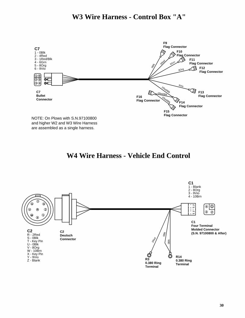
NOTE: On Plows with S.N.97100800 and higher W2 and W3 Wire Harness are assembled as a single harness.
30
W3 Wire Harness - Control Box "A"
W4 Wire Harness - Vehicle End Control
C2Deutsch Connector
R30.380 Ring Terminal
C1Four Terminal Molded ConnectorC2
R - 2RedS - 0BlkT - Key PinU - 0BlkV - 8OrgW - 10BrnX - Key PinY - 9VioZ - Blank
2Red
RV
UT
S
YX
W
Z
C1 1 - Blank2 - 8Org3 - 9Vio4 - 10Brn
4 1
3 2
R140.380 Ring Terminal
0Blk
0Blk
NOTE: On Plows with S.N.97100800 and higher W2 and W3 Wire Harness are assembled as a single harness.
(S.N. 97100800 & After)
C7Bullet Connector
F9 Flag Connector
F10 Flag Connector
F11 Flag Connector
F12 Flag Connector
F13 Flag Connector
F14 Flag Connector
F15 Flag Connector
F16 Flag Connector
C7 1 - 0Blk2 - 4Red3 - 1Red/Blk4 - 6Grn5 - 8Org6 - 9Vio 0B
lk 5Red
6Grn
8Org
9Vio1Red/Blk1Red/Blk1Red/Blk
2
1 6
5
3 4
31
RV
UT
S
YX
W
Z
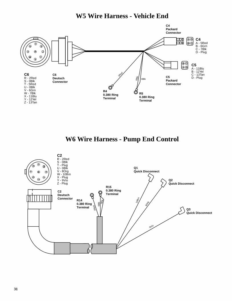
W5 Wire Harness - Vehicle End
C6Deutsch Connector
C4Packard Connector
C5Packard Connector
R40.380 Ring Terminal
R50.380 Ring Terminal
C5 A - 11BluB - 12YelC - 13TanD - Plug
C4 A - 5RedB - 6GrnC - 7BlkD - Plug
C6 R - 2RedS - 0BlkT - 5RedU - 0BlkV - 6GrnW - 7BlkX - 11BluY - 12YelZ - 13Tan
2Red
0Blk
0Blk
A
B C
D
B
A D
C
W6 Wire Harness - Pump End Control
C2Deutsch Connector
Q1 Quick Disconnect
Q2 Quick Disconnect
Q3 Quick Disconnect
10B
rn
8Org
9Vio
RZ
ST
U WX
Y
V
C2 R - 2RedS - 0BlkT - PlugU - 0BlkV - 8OrgW - 10BrnX - PlugY - 9VioZ - Plug
R140.380 Ring Terminal
R150.380 Ring Terminal
2Red 0B
lk 0Blk

32
W7 Wire Harness - Pump End Main
C6Deutsch Connector
R60.310 Ring Terminal
R70.310 Ring Terminal
Q4 Quick Disconnect
Q5 Quick Disconnect
Q6 Quick Disconnect
Q7 Quick Disconnect
Q8 Quick Disconnect
Q9 Quick Disconne
Q10 Quick Disconnect
Q11 Quick Disconnect
Q12 Quick Disconnect
Q13 Quick Disconnect
P3Push-On Connector
P4Push-On Connector
P5Push-On Connector
P6Push-On Connector
C6 R- 2RedS- 0BlkT- 5RedU- 0BlkV- 6GrnW- 7Blu/WhtX- 11BluY- 12YelZ - 13Tan
2Red
0Blk
11B
lu
0Blk
7Blu/Wht
12Ye
l
13Ta
n
6Grn
5Red
13Ta
n
0Blk
0Blk
0Blk
0Blk
0Blk
0Blk0Blk
0Blk
RZ
ST
U WX
Y
V

33
W9 Wire Harness - Battery Power
R80.380 Ring Terminal
R90.250 Ring Terminal
2Red
W10 Wire Harness - Battery Ground
R120.380 Ring Terminal
R13#10 Ring Terminal
0Blk
W11 Wire Harness - Solenoid Switch Power
R100.380 Ring Terminal
R110.250 Ring Terminal
2Red
W12 Wire Harness - Jackstand Switch Jumper
1Blu
S9 Slip OnConnector
Q14 Quick Disconnect
W13 Wire Harness - Jackstand Switch Jumper
2Yel
W14 Wire Harness - Control Box Jumper (2 Req.)
Pnk
S10 Slip OnConnector
F17 Flag Connector
F18 Flag Connector
S11 Slip OnConnector
W8 Wire Harness (No Longer Used)

SNO-WAY PLOWS
LIMITED ONE-YEAR WARRANTYSNO-WAY Warrants to the original retail purchaser for a period of one (1) year from the date ofdelivery from an authorized SNO-WAY Dealer that your new SNO-WAY Plow is free fromdefects in materials and workmanship if properly set up and operated in accordance with therecommendations set forth in SNO-WAY’s Set-up and Operator’s Manuals. This warranty doesnot cover normal wear items. Normal wear items include, but are not exclusive to, shoes, wearstrips,markers, pins, and bushings.
SNO-WAY Plows used by a dealer as a demonstrator shall be warranted only for the period ofone (1) year from the date of delivery to said dealer and the first subsequent purchaser shallbe entitled to the remaining warranty protection.
This warranty shall not apply to any item of equipment which has been repaired or alteredoutside the SNO-WAY factory or authorized SNO-WAY dealership or which has been subjectto misuse, negligence or accident: neither shall it apply to equipment which has not beenoperated in accordance with SNO-WAY printed instructions or has been operated beyond theSNO-WAY’S recommended snow plow operating class.
To validate this warranty, your dealer and you must complete the enclosed WarrantyRegistration Card at time of purchase of the plow and return the Factory copy to SNO-WAYInternational, Inc. within ten (10) days following delivery of your new Plow.
To obtain warranty service, promptly return your Plow or any defective part at your expense toany authorized SNO-WAY dealer during the warranty period. Replacement or repair ofdefective or inadequate parts shall be performed without charge for labor or materials by suchdealer at his regular place of business during regular business hours after inspection anddetermination that the warranty applies.
EXCLUSIONS OF WARRANTY
Except as otherwise expressly stated herein, SNO-WAY makes no representation of warrantyof any kind expressed or implied, including merchantability or fitness for particular purpose inrespect to the equipment.
SNO-WAY shall not be liable for incidental or consequential damages for any breach ofwarranty, including but not limited to loss of use, inconvenience, rental or replacementequipment, loss of profits or other commercial loss.
No agent, employee or representative of SNO-WAY has any authority to bind SNO-WAY to anyaffirmation, representation or warranty concerning its equipment except as specifically setforth herein.
Certain limitations expressed herein are excludable in accordance with provisions of local law.Such limitations shall be deemed struck if such local law is applicable. All other limitations andprovisions shall continue to apply.
SNO-WAY INTERNATIONAL, INC.

SNO-WAY® INTERNATIONAL, INC.
©2000 Sno-Way® International