owner’s manual - national vacuum...
TRANSCRIPT

National Vacuum Equipment
Owner’s Manual
607 Challenger Series Rotary Vane Vacuum Pumps
MADEIN USA
Visit our web site to download pump setup guides, brochures and other technical information.

2 | 607 Challenger Series www.natvac.com | 800.253.5500
© 2012 National Vacuum Equipment, Inc.Revision: 4 (Release) March 2012
No part of this manual may be reproduced without the written permission of National Vacuum Equipment, Inc.
607 Challenger
Owner’s Record Date of Purchase: _________________________ Purchased from: __________________________ Serial Number: ____________________________

607 Challenger Series | 3www.natvac.com | 800.253.5500
Counter ClockwiseRotation
ClockwiseRotation
IMPORTANT INFORMATION FOR INSTALLING PUMP
607 CHALLENGER SERIES PUMPS AERIAL VIEW
SHADED AREA MUST BE KEPT CLEAR FOR SERVICING THE FILTER

4 | 607 Challenger Series www.natvac.com | 800.253.5500
ContentsIntroduction 5 General Information .........................................................5
Limited Warranty 6 Warranty ..........................................................................6
607 Challenger 9 Application .......................................................................9 PumpSpecifications ........................................................9 System Requirements ...................................................10 Drive System ................................................................11 Factory Settings .............................................................11 Adjusting Factory Oil Settings .......................................12
Operating Instructions 13 Normal Operation .........................................................13 Recommended Lubricant ..............................................14 Maintenance ..................................................................15 Cold Weather Operation ................................................16
Troubleshooting 17 Pump overheats ............................................................17 Pump uses too much oil ................................................17 Pump doesn’t turn .........................................................17 No vacuum ....................................................................18 System Troubleshooting ................................................18 Making a vacuum tester ................................................19
Parts Breakdown 20 607 Challenger Series Vacuum Pumps Parts List .........20 607 Fan Cooled Parts Diagram .....................................23 607 Liquid Cooled Parts Diagram ..................................24 607 SV Parts Diagram ...................................................25 607 Fan Cooled Parts Oil Line Routing .........................26 607 Liquid Cooled Oil Line Routing ...............................27 Automatic Oil Pump Parts List (Three Outlet) ...............28 Automatic Oil Pump Parts Diagram (Three Outlet) .......29 Automatic Oil Pump Parts List (Four Outlet) .................30 Automatic Oil Pump Parts Diagram (Four Outlet) .........31

607 Challenger Series | 5www.natvac.com | 800.253.5500
IntroductionGeneral Information
About National Vacuum EquipmentCongratulations! You now own a quality vacuum/pressure pump proudly manufactured in the U.S.A. by National Vacuum Equipment, Inc. You havenotonlyacquiredasuperiorpieceofequipmentfromaqualifieddealer, you have hired a team of vacuum experts. We stand ready to work with your dealer to answer your questions and provide you with the information necessary to keep your equipment in peak working condition.
Thank you for using National Vacuum Equipment.
Our MissionWe are dedicated to the manufacture and wholesale distribution of quality vacuum system products at a reasonable price, on a timely basis. We are a “one-stop shop” for manufacturers and distributors of vacuum equip-ment.
Our HistoryNational Vacuum Equipment, Inc. was founded in 1980 by Bruce Luoma. The Company started as a retailer of vacuum pumps. Soon after it started, the Company secured the rights to exclusive distribution of the Battioni vacuum pumps in North America. This helped the Company to evolve into its current status as a wholesale supplier.
To reach the goal of becoming a full service supplier of vacuum system components, the Company began fabrication its own line of componen-try, purchased and developed its own line of vacuum pumps, and began purchasing for resale various valves and accessories.
Today, NVE has full service machine, fabrication and powder-coating shops complete with CNC-controlled production equipment designed for close tolerance work. The company has a highly trained staff all of whom are dedicated to quality.

6 | 607 Challenger Series www.natvac.com | 800.253.5500
Warranty
National Vacuum Equipment, Inc.
Guarantees that the product it provides is free of manufactur-er’s defects, including materials and workmanship. Properly installed and maintained product is warranted for a period of one (1) year subject to the following conditions:
1. A properly completed warranty registration card must be received by us within 30 days of sale to end user for pump sales to be considered warrantable. All pumps received for warranty consideration must retain the original NVE serial number tag.
2. The one (1) year period shall begin the day the product is shipped from our warehouse, unless we are provided with an authentic copy of the original resale invoice, in which case the one (1) year period shall begin at such invoice date.
3. The covered product must be used in an application for which it was intended. We do not recommend our product for particular uses or applications.
4. Vane breakage, or damage caused by vane breakage, is not warrantable.
5. Damage caused by improper use or lack of proper maintenance is not warrantable.
6. Manufacturer’s liability under this or any other warranty, whether express or implied, is limited to repair of or, at the manufacturer’s option, replacement of parts which are shown to have been defective when shipped
Limited Warranty
607 Challenger

607 Challenger Series | 7www.natvac.com | 800.253.5500
7. Manufacturer’s liability shall not be enforceable for any product until National Vacuum Equipment, Inc. has been paid in full for such product.
8. Except to the extent expressly stated herein, manufacturer’s liability for incidental and consequential damage is hereby excluded to the full extent permitted by law.
9. Manufacturer’s liability as stated herin cannot be altered exceptinwritingsignedbyanofficerofNationalVacuum Equipment, Inc.
10. Certain products provided by National Vacuum Equipment, Inc. are covered by their respective manufacturer’s warran-ties (e.g., engines used in the NVE engine drive packages). These products are not covered by the National Vacuum Equipment, Inc. Manufacturer’s Warranty.
11. Final assemblers responsibility. NVE goes to great lengths to insure the quality and proper functionality of the products it supplies. Many products we supply are purchased for resale or are impossible or impractical to test prior to the in-stallation of the item in a vacuum system. It is therefore the responsibilityofthefinalassemblertothoroughlytestthevacuum system and components supplied to the assembler byNVEpriortothedeliveryofthefinalproducttotheenduser.
12. Not responsible for pump coupling tightness or alignment. Customer needs to inspect periodically to ensure proper alignment and to check tightness of set screws.
Any items found to be defective after delivery to the end user that should have been discovered prior to deliver will qualify replace-ment of the defective part only with absolutely no compensation for outside labor or travel expenses. Any subsequent damage to other components caused by the defective part will be the sole responsi-bility of the assembler.

8 | 607 Challenger Series www.natvac.com | 800.253.5500
____________________________________________________Warranty Procedures
Should a potential warranty situation arise, the following procedures must be followed:
•Contact your dealer or NVE immediately upon the occurrence of the event and within the warranty period.
•Customer must receive a return goods authorization (RGA) before returning product.
•All serial-numbered products must retain the NVE serial numbertagtobequalifiedforwarranty.
•Product must be returned to NVE intact for inspection before warranty will be honored.
•Product must be returned to NVE freight prepaid in the most economical way.
•Credit will be issued for material found to be defective upon our inspection, based upon prices at the time of purchase.

607 Challenger Series | 9www.natvac.com | 800.253.5500
Application
Designed for extended operation
•Duty cycle will vary depending on several factors, such as altitude, RPM & ambient temperature.
•The 607 Challenger is a severe duty vacuum pump, designed to be used in liquid waste pumping systems where extended operation is desired.
•Proven applications are:
-Oilfield -Septic - Restaurant Grease - Industrial Waste
Pump Specifications
607 Calculated Flow Data
607 Challenger
Model-Specific Information
RPM
Pressure (PSI) Free Flow Vacuum (in Hg)
20 15 10 5 0 5 10 15 20 25 27
**1500Hp 34 32 29 27 23 23 22 21 20 19 19
CFM 282 291 301 331 357 348 338 331 310 282 244
*1250Hp 29 27 24 23 20 20 19 16 15 14 14
CFM 229 237 244 269 290 282 275 269 252 229 198
1000Hp 26 23 20 18 15 15 14 14 13 12 12
CFM 178 184 190 209 226 220 214 209 196 178 155
* 1250 RPM Recommended range.
** 1500 RPM Intermittent use only
10 | 607 Challenger Series www.natvac.com | 800.253.5500
System Requirements High Quality Components•The 607 Challenger is a high performance vacuum pump and requires compatible, high quality components as manufactured by NVE.
Shutoffs•We recommend an 8” cage and a 6” S.S. ball which is standard in all of our primary and secondary shutoffs.
Hose•Use 3” or larger hose to plumb your system. We recommend you use a hose that can withstand high temperatures such as hot tar-asphalt hose.
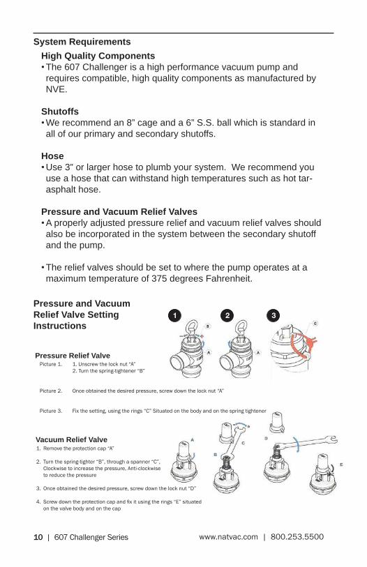
Pressure and Vacuum Relief Valves•A properly adjusted pressure relief and vacuum relief valves should also be incorporated in the system between the secondary shutoff and the pump.
•The relief valves should be set to where the pump operates at a maximum temperature of 375 degrees Fahrenheit.
1. Remove the protection cap “A”
2. Turn the spring-tighter “B”, through a spanner “C”, Clockwise to increase the pressure, Anti-clockwise to reduce the pressure
3. Once obtained the desired pressure, screw down the lock nut “D”
4. Screw down the protection cap and fix it using the rings “E” situated on the valve body and on the cap
1 2 3
Picture 1. 1. Unscrew the lock nut “A” 2. Turn the spring-tightener “B”
Picture 2. Once obtained the desired pressure, screw down the lock nut “A”
Picture 3. Fix the setting, using the rings “C” Situated on the body and on the spring tightener
Pressure and Vacuum Relief Valve Setting Instructions
Vacuum Relief Valve
Pressure Relief Valve

607 Challenger Series | 11www.natvac.com | 800.253.5500
Drive System
•The pump should be mounted on a level, horizontal surface, secured with grade 8 fasteners.
•The drive system should be sized to supply the required horsepower to the pump plus a reserve to insure long life.
•The P.T.O. must be slowly engaged or it will damage the pump and drive components.
•Make certain that all shafts, pulleys or turning parts are properly guarded.
•Check the ratio of the drive system prior to installation to verify that the pump will be turning at the proper speed.
Direction of Rotation
•The direction of rotation and RPM are marked on the front of the pump.
•The direction of rotation required by your drive system should be determined prior to ordering the pump. Please payspecialattentiontotheorientationofthefinalfilter,which varies with rotation.
Factory Settings
•The automatic lubrication pumps are set at the factory during pump testing and should require no further adjustment during pump installation. The pump should consume 12 oz. - 15 oz. of oil per hour. Please contact us if oil usage is outside of these parameters.
•It is the responsibility of the installer to ensure proper vacuum and pressure settings and RPM.
12 | 607 Challenger Series www.natvac.com | 800.253.5500
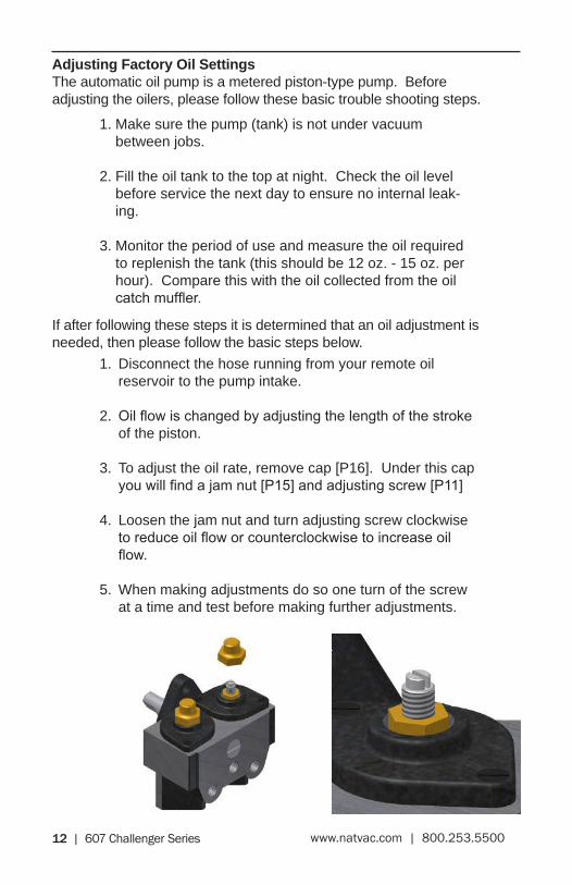
Adjusting Factory Oil SettingsThe automatic oil pump is a metered piston-type pump. Before adjusting the oilers, please follow these basic trouble shooting steps.
If after following these steps it is determined that an oil adjustment is needed, then please follow the basic steps below.
1. Make sure the pump (tank) is not under vacuum between jobs.
2. Fill the oil tank to the top at night. Check the oil level before service the next day to ensure no internal leak-ing.
3. Monitor the period of use and measure the oil required to replenish the tank (this should be 12 oz. - 15 oz. per hour). Compare this with the oil collected from the oil catchmuffler.
1. Disconnect the hose running from your remote oil reservoir to the pump intake.
2. Oilflowischangedbyadjustingthelengthofthestrokeof the piston.
3. To adjust the oil rate, remove cap [P16]. Under this cap youwillfindajamnut[P15]andadjustingscrew[P11]
4. Loosen the jam nut and turn adjusting screw clockwise toreduceoilfloworcounterclockwisetoincreaseoilflow.
5. When making adjustments do so one turn of the screw at a time and test before making further adjustments.

607 Challenger Series | 13www.natvac.com | 800.253.5500
Operating Instructions
607 Challenger
Normal Operation
Oil Reservoir• Checkoilreservoirdailyandfillasrequired.
• Drain and clean periodically depending on service.
Temperature• Check exhaust temperature. It must not exceed 375 degrees
Fahrenheit at any time.
Recommended RPM• Do not operate the pump faster than the recommended rpm of
1250. 1500 RPM is for intermittent use only.
• Too low of an RPM can cause the vanes to clatter (inconsistent contact with the housing) causing wear.
Suction Valve• To operate the suction valve, move the handle in the appropriate
direction for either vacuum or pressure; center is neutral.
Vacuum Levels• Do not operate your pump for extended periods of time at
vacuum levels which cause the pump to exceed 375 degrees Fahrenheit exhaust gas temperature.
Guards• Make certain all guards are in place prior to running your pump.
Think Safety!

14 | 607 Challenger Series www.natvac.com | 800.253.5500
Recommended Lubricant
• We recommend that turbine oil be used in our pumps. Turbine oil is much more resistant to breakdown due to heat than normal motor oil, thereby avoiding the prob-lems associated with motor oil such as lacquering and excessive wear.
•Acceptable oils include:
1. *NVE ISO 68 Oil
2. Penzoil Penzabell 68 T.O.
3. Shell Turbo 68
4. Mobil D.T.E. Heavy - Medium
5. Texaco Regal R & O 68
* NVE ISO 68 Oil is our recommended pump oil for the Challenger series vacuum pumps. Challenger Vacuum Pump Oil is sold by the case, six 1 gallon containers of oil per case.

607 Challenger Series | 15www.natvac.com | 800.253.5500
Maintenance
Washing• Periodically wash the mud and dirt off of your pump as it
must be clean to allow heat to radiate from it.
FlushingWerecommendperiodicflushingofyourpump.Todothis:
1. Connectthehosetotheflushvalvelocatedonthesideofthe inlet port.
2. Put the end of the hose in a one pint container of diesel fuel. Start your pump and run as slow as possible.
3. With the suction valve in the vacuum position, monitor the dieselflowtoyourpump.
4. When the diesel fuel is gone, switch the suction valve to neutral and run the pump for 2 minutes.
5. Speed the pump up to normal RPM, switch the suction valve to vacuum.
6. Remove the hose and close the valve.
7. Properlydisposeofusedoilandflushingfluid.
Checking Vane Wear• We recommend checking vane wear at least every 12
months.
• Anewvaneisflushwiththeoutsidediameteroftherotor.
• Remove the plug from the vane check port, insert a rod to rotor O.D., rotate rotor until the rod falls into one of the vane slots. If the rod falls more than a 1/4” into any of the 7 vane slots, it’s time to replace the vanes.
• Vanes should be replaced in sets and it is always a good idea to have an extra set of vanes on hand for emergen-cies.

16 | 607 Challenger Series www.natvac.com | 800.253.5500
Cold Weather Operation
Confirm pump is not frozen.• Priortoengagingthepump,turnbyhandtoconfirmitis
not frozen.
If pump is frozen, thaw it.• If the pump is frozen, thaw it out by moving the truck into
a heated building.
Avoid freezing problems• You can avoid freezing problems by putting a small
amount of diesel fuel into the pump at the end of the day.
607 Challenger Series | 17www.natvac.com | 800.253.5500
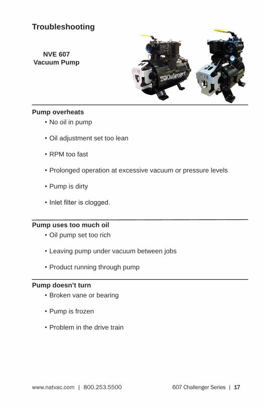
Troubleshooting
NVE 607 Vacuum Pump
Pump overheats
•No oil in pump
•Oil adjustment set too lean
•RPM too fast
•Prolonged operation at excessive vacuum or pressure levels
•Pump is dirty
•Inletfilterisclogged.
Pump uses too much oil
•Oil pump set too rich
•Leaving pump under vacuum between jobs
•Product running through pump
Pump doesn’t turn
•Broken vane or bearing
•Pump is frozen
•Problem in the drive train

18 | 607 Challenger Series www.natvac.com | 800.253.5500
No vacuum
•Suction valve is in neutral
•Worn seals or vanes
•Pump is not turning fast enough
•Check valve or suction valve is clogged
•Leakinthetankorfittings
•Collapsed hose between the pump and shutoffs
•Inletfilterclogged
System Troubleshooting Locating the source of the trouble
If you notice a decrease in pump performance, start troubleshooting at the pump.
• Remove the suction and discharge hoses at the pump.
• Start the pump and run it in vacuum only at its normal rpm
• Check the vacuum level at the pump inlet. The 607 Challenger in new condition will develop 27-28.5” hg.
• If the pump checks out ok, check the vacuum level at the secondary, then the primary shutoff. Keep working your waybackuntilyoufindtheproblem.
For rebuild instructions please visit our website atwww.natvac.com or call us at 800-253-5500

607 Challenger Series | 19www.natvac.com | 800.253.5500
Making a vacuum tester
1. Procureaflangetomountonyour4-wayvalve,ashort 3” pipe nipple, a 3” pipe cap and a vacuum gage.
2. Drill and tap a 1/4” N.P.T. thread in the pipe cap.
3. Assembletheflange,nipple,pipecapand vacuum gage.
4. Removeaflangefromthefour-wayvalveonyourpump.
5. Startthepumpandconfirmthelocationyouhavechosen to test from is at vacuum.
6. UsingtheexistingO-ring,fastenthetestingflangeto your pump.
7. Start your pump and read the vacuum level on the gauge.
20 | 607 Challenger Series www.natvac.com | 800.253.5500
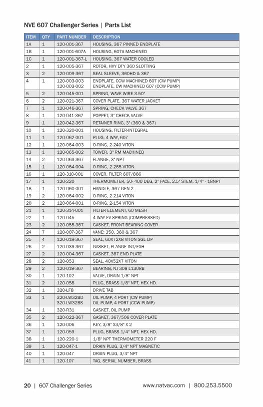
ITEM QTY PART NUMBER DESCRIPTION1A 1 120-001-367 HOUSING, 367 PINNED ENDPLATE1B 1 120-001-607A HOUSING, 607A MACHINED1C 1 120-001-367-L HOUSING, 367 WATER COOLED2 1 120-005-367 ROTOR, HVY DTY 360 SLOTTING3 2 120-009-367 SEAL SLEEVE, 360HD & 3674 1 120-003-003
120-003-002ENDPLATE, CCW MACHINED 607 (CW PUMP)ENDPLATE, CW MACHINED 607 (CCW PUMP)
5 2 120-045-001 SPRING, WAVE WIRE 3.50"6 2 120-021-367 COVER PLATE, 367 WATER JACKET7 1 120-046-367 SPRING, CHECK VALVE 3678 1 120-041-367 POPPET, 3" CHECK VALVE9 1 120-042-367 RETAINER RING, 3" (360 & 367)10 1 120-320-001 HOUSING, FILTER-INTEGRAL11 1 120-062-001 PLUG, 4-WAY, 60712 1 120-064-003 O-RING, 2-240 VITON13 1 120-065-002 TOWER, 3" RM MACHINED14 2 120-063-367 FLANGE, 3" NPT15 1 120-064-004 O-RING, 2-265 VITON16 1 120-310-001 COVER, FILTER 607/86617 1 120-220 THERMOMETER, 50- 400 DEG, 2" FACE, 2.5" STEM, 1/4" - 18NPT18 1 120-060-001 HANDLE, 367 GEN 219 2 120-064-002 O-RING, 2-214 VITON20 2 120-064-001 O-RING, 2-154 VITON21 1 120-314-001 FILTER ELEMENT, 60 MESH22 1 120-045 4-WAY FV SPRING (COMPRESSED)23 2 120-055-367 GASKET, FRONT BEARING COVER24 7 120-007-367 VANE: 350, 360 & 36725 4 120-018-367 SEAL, 60X72X8 VITON SGL LIP26 2 120-039-367 GASKET, FLANGE INT/EXH27 2 120-004-367 GASKET, 367 END PLATE28 2 120-053 SEAL, 40X52X7 VITON29 2 120-019-367 BEARING, NJ 308 L1308B30 1 120-102 VALVE, DRAIN 1/8" NPT31 2 120-058 PLUG, BRASS 1/8" NPT, HEX HD.32 1 320-LF8 DRIVE TAB33 1 320-LW32BD
320-LW32BSOIL PUMP, 4 PORT (CW PUMP)OIL PUMP, 4 PORT (CCW PUMP)
34 1 320-R31 GASKET, OIL PUMP35 2 120-022-367 GASKET, 367/506 COVER PLATE36 1 120-006 KEY, 3/8" X3/8" X 237 1 120-059 PLUG, BRASS 1/4" NPT, HEX HD.38 1 120-220-1 1/8" NPT THERMOMETER 220 F39 1 120-047-1 DRAIN PLUG, 3/4" NPT MAGNETIC40 1 120-047 DRAIN PLUG, 3/4" NPT41 1 120-107 TAG, SERIAL NUMBER, BRASS
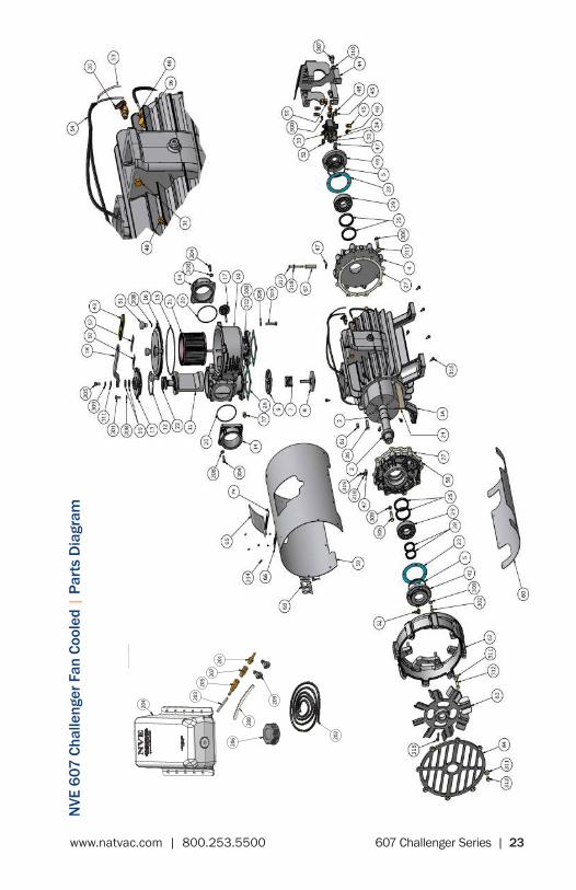
NVE 607 Challenger Series | Parts List
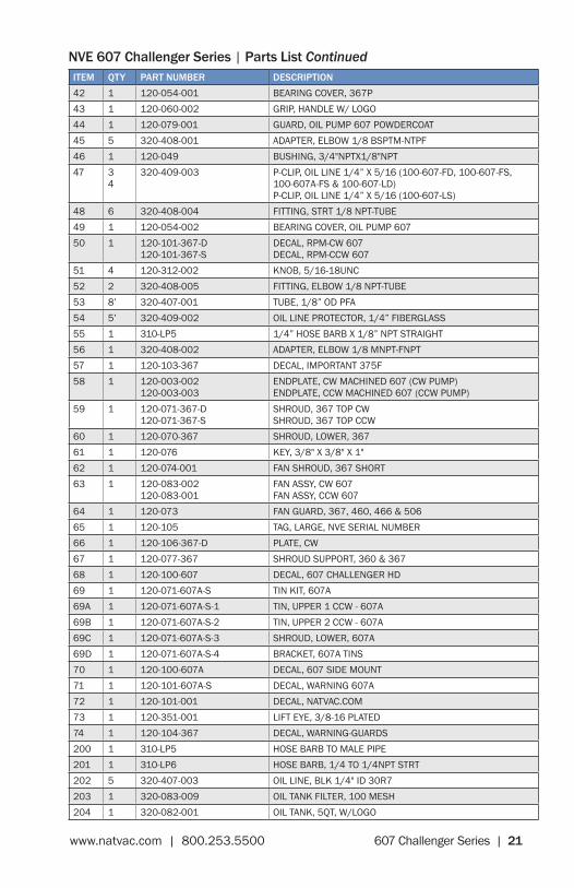
607 Challenger Series | 21www.natvac.com | 800.253.5500
NVE 607 Challenger Series | Parts ListITEM QTY PART NUMBER DESCRIPTION42 1 120-054-001 BEARING COVER, 367P43 1 120-060-002 GRIP, HANDLE W/ LOGO44 1 120-079-001 GUARD, OIL PUMP 607 POWDERCOAT45 5 320-408-001 ADAPTER, ELBOW 1/8 BSPTM-NTPF46 1 120-049 BUSHING, 3/4"NPTX1/8"NPT47 3
4320-409-003 P-CLIP, OIL LINE 1/4” X 5/16 (100-607-FD, 100-607-FS,
100-607A-FS & 100-607-LD)P-CLIP, OIL LINE 1/4” X 5/16 (100-607-LS)
48 6 320-408-004 FITTING, STRT 1/8 NPT-TUBE49 1 120-054-002 BEARING COVER, OIL PUMP 60750 1 120-101-367-D
120-101-367-SDECAL, RPM-CW 607DECAL, RPM-CCW 607
51 4 120-312-002 KNOB, 5/16-18UNC52 2 320-408-005 FITTING, ELBOW 1/8 NPT-TUBE53 8’ 320-407-001 TUBE, 1/8” OD PFA54 5’ 320-409-002 OIL LINE PROTECTOR, 1/4” FIBERGLASS55 1 310-LP5 1/4” HOSE BARB X 1/8” NPT STRAIGHT56 1 320-408-002 ADAPTER, ELBOW 1/8 MNPT-FNPT57 1 120-103-367 DECAL, IMPORTANT 375F58 1 120-003-002
120-003-003ENDPLATE, CW MACHINED 607 (CW PUMP)ENDPLATE, CCW MACHINED 607 (CCW PUMP)
59 1 120-071-367-D 120-071-367-S
SHROUD, 367 TOP CWSHROUD, 367 TOP CCW
60 1 120-070-367 SHROUD, LOWER, 36761 1 120-076 KEY, 3/8" X 3/8" X 1"62 1 120-074-001 FAN SHROUD, 367 SHORT63 1 120-083-002
120-083-001FAN ASSY, CW 607FAN ASSY, CCW 607
64 1 120-073 FAN GUARD, 367, 460, 466 & 50665 1 120-105 TAG, LARGE, NVE SERIAL NUMBER66 1 120-106-367-D PLATE, CW67 1 120-077-367 SHROUD SUPPORT, 360 & 36768 1 120-100-607 DECAL, 607 CHALLENGER HD69 1 120-071-607A-S TIN KIT, 607A69A 1 120-071-607A-S-1 TIN, UPPER 1 CCW - 607A69B 1 120-071-607A-S-2 TIN, UPPER 2 CCW - 607A69C 1 120-071-607A-S-3 SHROUD, LOWER, 607A69D 1 120-071-607A-S-4 BRACKET, 607A TINS70 1 120-100-607A DECAL, 607 SIDE MOUNT71 1 120-101-607A-S DECAL, WARNING 607A72 1 120-101-001 DECAL, NATVAC.COM73 1 120-351-001 LIFT EYE, 3/8-16 PLATED74 1 120-104-367 DECAL, WARNING-GUARDS200 1 310-LP5 HOSE BARB TO MALE PIPE201 1 310-LP6 HOSE BARB, 1/4 TO 1/4NPT STRT202 5 320-407-003 OIL LINE, BLK 1/4" ID 30R7203 1 320-083-009 OIL TANK FILTER, 100 MESH204 1 320-082-001 OIL TANK, 5QT, W/LOGO
NVE 607 Challenger Series | Parts List Continued

22 | 607 Challenger Series www.natvac.com | 800.253.5500
ITEM QTY PART NUMBER DESCRIPTION303 4 HHCS - 5/16-18 UNC X 2 FT HHCS - 5/16-18 UNC X 2 FULL THREAD304 8 SHCS - 5/16-18 UNC X 1 SHCS - 5/16-18 UNC X 1305 1 HHCS - 3/8-16 UNC x 0.75 HHCS - 3/8-16 UNC X 0.75306 10 HHCS - 3/8-16 UNC X 1.75 HHCS - 3/8-16 UNC X 1.75307 4 HHCS - 1/2-13 UNC X 1.00 HHCS - 1/2-13 UNC X 1.00308 36 LW - 5/16 LOCK WASHER, 5/16309 3 LW - 3/8 LOCK WASHER, 3/8"310 4 LW - 1/2 LOCK WASHER, 1/2311 23 FW - 3/8 FLAT WASHER, 3/8"312 6 HHCS - 3/8-16 UNC X 2.25 HHCS - 3/8-16 UNC X 2.25313 8 HHCS - 3/8-16 UNC X 0.50 HHCS - 3/8-16 UNC X 0.50314 4 RVT 1/8 D X 1/8L BLIND RIVET, 1/8 DIA X 1/8 GRIP, ALUM315 1 SHCS - 5/16-24 UNF X 1.25 SHCS - 5/16-24 UNF X 1.25316 14 TAPSCR - 1/4-14 X 0.75 HEX HEAD SELF TAPPING SCREW 1/4-14317 1 HHCS 1/4-20 UNC X 2.75 HHCS 1/4-20 UNC X 2.75318 2 FW - 1/4 USS FLAT WASHER - 1/4" USS319 1 BHCS - 1/4-20 UNC X 0.50 BHCS - 1/4-20 UNC X 0.50320 1 HEX NUT - 3/8 UNC HEX NUT - 3/8 UNC
NVE 607 Challenger Series | Parts List Continued
607 Challenger Series | 23www.natvac.com | 800.253.5500
NVE 607 Challenger Series | Parts List ContinuedN
VE 6
07 C
halle
nger
Fan
Coo
led
| Pa
rts
Dia
gram
204
206 20
2
208
203
205
207
201
209

24 | 607 Challenger Series www.natvac.com | 800.253.5500
NVE
607
Cha
lleng
er L
iqui
d Co
oled
| P
arts
Dia
gram
204
206 20
2
208
203
205
207
201
209

607 Challenger Series | 25www.natvac.com | 800.253.5500
NVE
607
SV
Chal
leng
er F
an C
oole
d |
Part
s D
iagr
am
204
206 20
2
208
203
205
207
201
209

26 | 607 Challenger Series www.natvac.com | 800.253.5500
607
Cha
lleng
er -
Fan
Coo
led
- Oil
Line
Rou
ting
SECT
ION
B-B
SCAL
E 1
/ 4
SECT
ION
E-E
SCAL
E 1
/ 4
SECT
ION
F-F
SCAL
E 1
/ 4
MO
UN
TIN
G H
OLE
LO
CATI
ON
SVI
EW G
-GSC
ALE
1 /
4
1 1
2 2
3 3
4 4
5 5
6 6
7 7
8 8
AA
BB
CC
DD
NVE
Nat
iona
lVa
cuum
Eq
uipm
ent,
Inc
.26
70 A
ero
Park
Driv
e, T
rave
rse
City
, MI
4968
6Ph
one:
(23
1) 9
41-0
215
F
ax:
(231
) 94
1-23
54
TO
LE
RA
NC
ES
UN
LE
SS
OT
HE
R W
ISE
SP
EC
IFIE
D
On
e p
lace
(.X
)
±.1
Tw
o p
lace
s (.
XX
)
±.0
3T
hre
e p
lace
s (.
XX
X)
±.01
5A
ng
les
±1°
All
mac
hin
ed s
urf
aces
125
RM
S m
ax.
Rem
ove
all
bu
rrs
and
sh
arp
ed
ges
.C
AD
dra
win
g -
NO
man
ual
ch
ang
es.
All
dim
ensi
on
s in
inch
es u
nle
ss s
pec
ifie
d.
Th
is d
ocu
men
t m
ay c
on
tain
co
nfi
den
tial
tra
de
secr
et in
form
atio
n w
hic
h is
th
e ex
clu
sive
pro
per
ty o
f N
atio
nal
Vac
uu
m E
qu
ipm
ent.
An
yin
form
atio
n o
n t
his
dra
win
g is
no
t to
be
dis
clo
sed
to
an
yon
e n
ot
hav
ing
a "
Nee
d t
oK
no
w."
Th
e in
form
atio
n c
on
tain
ed h
erei
n is
to
be
use
d o
nly
in a
cco
rdan
ce w
ith
th
e b
est
inte
rest
s o
f N
atio
nal
Vac
uu
m E
qu
ipm
ent.
PA
RT
NA
ME
:
607
CHAL
LEN
GER
, FAN
CO
OLE
DM
AT
ER
IAL
:
DR
AW
N B
Y:
SC
AL
E:
CH
EC
KE
D B
Y:
DA
TE
:
RP
TB
OB
PA
RT
NO
.S
HE
ET
2 10
0-60
7-F
(D &
S)
2 o
f1:4SE
E B
OM
APPR
OX.
WT.
CAD
FIL
E LO
CATI
ON
: P:
\Dat
a\CA
D -
Pro
duct
ion\
100-
607-
FD &
S.id
w
SHEE
T SI
ZED 39
8 LB
S
BB
E E
F F
GG
100-
607-
FD (
CLO
CKW
ISE)
100-
607-
FS (
COU
NTE
R C
LOCK
WIS
E)
(14.
925)
(6.5
49)
(28.
918)
(3.1
97)
(8.1
52)
(18.
609)
(23.
669)
(4.0
00)
3" F
EMAL
E N
PT
(28.
911)
(14.
925)
(8.1
52)
(18.
609)(2
3.66
9)
(4.0
00)
3" F
EMAL
E N
PT
(3.3
15)
B) F
RO
NT
BEAR
ING
B) F
RO
NT
BEAR
ING
D)
BORE
- FR
ON
T
A) R
EAR B
EARIN
G
B) F
RO
NT
BEAR
ING
B) F
RO
NT
BEAR
ING
D)
BORE
- FR
ON
TA)
REA
R B
EARIN
GREV
ISIO
N H
ISTO
RY
REV
DAT
ED
ESCR
IPTI
ON
APPR
OVE
DZO
NE
D3/
24/2
010
UPD
ATED
OIL
LIN
E LE
NG
THS
AND
EFF
ECTI
VE S
/NEC
N 1
122
-
E4/
28/2
010
UPD
ATED
OIL
PU
MP
GU
ARD
ECN
112
6-
F9/
8/20
10U
PDAT
ED O
P BE
ARIN
G
COVE
R A
ND
FIL
TER L
IDE
ECN
115
5-
G10
/25/
201
0U
PDAT
ED O
IL P
UM
P G
UAR
D
AND
SH
T 2
TEXT
ECN
118
3-
OIL
LIN
E RO
UTI
NG
: 10
0-60
7-FD
DES
IGN
ATIO
ND
ESCR
IPTI
ON
TYPE
PART
NU
MBE
RLE
NG
TH (
IN
AR. B
EARIN
GO
IL L
INE
320-
407-
001-
607F
D1
320-
409-
002-
607F
D1
7.25
5.25
BF.
BEA
RIN
GO
IL L
INE
PRO
TECT
OR
320-
407-
001-
607F
D2
320-
409-
002-
607F
D2
28.2
526
.00
CBO
RE
- REA
RO
IL L
INE
PRO
TECT
OR
320-
407-
001-
607F
D3
320-
409-
002-
607F
D3
11.0
09.
00
DBO
RE
- FR
ON
TO
IL L
INE
PRO
TECT
OR
320-
407-
001-
607F
D4
320-
407-
002-
607F
D4
22.7
520
.75
OIL
LIN
E RO
UTI
NG
: 10
0-60
7-FS
DES
IGN
ATIO
ND
ESCR
IPTI
ON
TYPE
PART
NU
MBE
RLE
NG
TH (
IN)
AR. B
EARIN
GO
IL L
INE
PRO
TECT
OR
320-
407-
001-
607F
S132
0-40
9-00
2-60
7FS1
7.25
5.25
BF.
BEA
RIN
GO
IL L
INE
PRO
TECT
OR
320-
407-
001-
607F
S232
0-40
9-00
2-60
7FS2
28.2
526
.00
CBO
RE-
REA
RO
IL L
INE
PRO
TECT
OR
320-
407-
001-
607F
S332
0-40
9-00
2-60
7FS3
15.0
013
.00
DBO
RE-
FRO
NT
OIL
LIN
EPR
OTE
CTO
R32
0-40
7-00
1-60
7FS4
320-
409-
002-
607F
S422
.75
20.7
5
( 1.
499)
(.37
5)(.
375)
(1.
499)
(.37
5)
(.37
5)
C) B
ORE
- REA
R
D)
BORE
- FR
ON
TC)
BO
RE
- REA
R
C) B
ORE
- REA
RD
) BO
RE
- FR
ON
T
C) B
ORE
- REA
R
NO
TE P
-CLI
P O
NBE
ARIN
G C
OVE
R NO
TE P
-CLI
P O
NBE
ARIN
G C
OVE
R
(5.7
50)
(11.
500)
(8.8
93)
(13.
500)
(5.5
16)
(8.9
56)
(13.
375)
(11.
032)
.6
88
SECT
ION
B-B
SCAL
E 1
/ 4
SECT
ION
E-E
SCAL
E 1
/ 4
SECT
ION
F-F
SCAL
E 1
/ 4
MO
UN
TIN
G H
OLE
LO
CATI
ON
SVI
EW G
-GSC
ALE
1 /
4
1 1
2 2
3 3
4 4
5 5
6 6
7 7
8 8
AA
BB
CC
DD
NVE
Nat
iona
lVa
cuum
Eq
uipm
ent,
Inc
.26
70 A
ero
Park
Driv
e, T
rave
rse
City
, MI
4968
6Ph
one:
(23
1) 9
41-0
215
F
ax:
(231
) 94
1-23
54
TO
LE
RA
NC
ES
UN
LE
SS
OT
HE
R W
ISE
SP
EC
IFIE
D
On
e p
lace
(.X
)
±.1
Tw
o p
lace
s (.
XX
)
±.0
3T
hre
e p
lace
s (.
XX
X)
±.01
5A
ng
les
±1°
All
mac
hin
ed s
urf
aces
125
RM
S m
ax.
Rem
ove
all
bu
rrs
and
sh
arp
ed
ges
.C
AD
dra
win
g -
NO
man
ual
ch
ang
es.
All
dim
ensi
on
s in
inch
es u
nle
ss s
pec
ifie
d.
Th
is d
ocu
men
t m
ay c
on
tain
co
nfi
den
tial
tra
de
secr
et in
form
atio
n w
hic
h is
th
e ex
clu
sive
pro
per
ty o
f N
atio
nal
Vac
uu
m E
qu
ipm
ent.
An
yin
form
atio
n o
n t
his
dra
win
g is
no
t to
be
dis
clo
sed
to
an
yon
e n
ot
hav
ing
a "
Nee
d t
oK
no
w."
Th
e in
form
atio
n c
on
tain
ed h
erei
n is
to
be
use
d o
nly
in a
cco
rdan
ce w
ith
th
e b
est
inte
rest
s o
f N
atio
nal
Vac
uu
m E
qu
ipm
ent.
PA
RT
NA
ME
:
607
CHAL
LEN
GER
, FAN
CO
OLE
DM
AT
ER
IAL
:
DR
AW
N B
Y:
SC
AL
E:
CH
EC
KE
D B
Y:
DA
TE
:
RP
TB
OB
PA
RT
NO
.S
HE
ET
2 10
0-60
7-F
(D &
S)
2 o
f1:4SE
E B
OM
APPR
OX.
WT.
CAD
FIL
E LO
CATI
ON
: P:
\Dat
a\CA
D -
Pro
duct
ion\
100-
607-
FD &
S.id
w
SHEE
T SI
ZED 39
8 LB
S
BB
E E
F F
GG
100-
607-
FD (
CLO
CKW
ISE)
100-
607-
FS (
COU
NTE
R C
LOCK
WIS
E)
(14.
925)
(6.5
49)
(28.
918)
(3.1
97)
(8.1
52)
(18.
609)
(23.
669)
(4.0
00)
3" F
EMAL
E N
PT
(28.
911)
(14.
925)
(8.1
52)
(18.
609)(2
3.66
9)
(4.0
00)
3" F
EMAL
E N
PT
(3.3
15)
B) F
RO
NT
BEAR
ING
B) F
RO
NT
BEAR
ING
D)
BORE
- FR
ON
T
A) R
EAR B
EARIN
G
B) F
RO
NT
BEAR
ING
B) F
RO
NT
BEAR
ING
D)
BORE
- FR
ON
TA)
REA
R B
EARIN
GREV
ISIO
N H
ISTO
RY
REV
DAT
ED
ESCR
IPTI
ON
APPR
OVE
DZO
NE
D3/
24/2
010
UPD
ATED
OIL
LIN
E LE
NG
THS
AND
EFF
ECTI
VE S
/NEC
N 1
122
-
E4/
28/2
010
UPD
ATED
OIL
PU
MP
GU
ARD
ECN
112
6-
F9/
8/20
10U
PDAT
ED O
P BE
ARIN
G
COVE
R A
ND
FIL
TER L
IDE
ECN
115
5-
G10
/25/
201
0U
PDAT
ED O
IL P
UM
P G
UAR
D
AND
SH
T 2
TEXT
ECN
118
3-
OIL
LIN
E RO
UTI
NG
: 10
0-60
7-FD
DES
IGN
ATIO
ND
ESCR
IPTI
ON
TYPE
PART
NU
MBE
RLE
NG
TH (
IN
AR. B
EARIN
GO
IL L
INE
320-
407-
001-
607F
D1
320-
409-
002-
607F
D1
7.25
5.25
BF.
BEA
RIN
GO
IL L
INE
PRO
TECT
OR
320-
407-
001-
607F
D2
320-
409-
002-
607F
D2
28.2
526
.00
CBO
RE
- REA
RO
IL L
INE
PRO
TECT
OR
320-
407-
001-
607F
D3
320-
409-
002-
607F
D3
11.0
09.
00
DBO
RE
- FR
ON
TO
IL L
INE
PRO
TECT
OR
320-
407-
001-
607F
D4
320-
407-
002-
607F
D4
22.7
520
.75
OIL
LIN
E RO
UTI
NG
: 10
0-60
7-FS
DES
IGN
ATIO
ND
ESCR
IPTI
ON
TYPE
PART
NU
MBE
RLE
NG
TH (
IN)
AR. B
EARIN
GO
IL L
INE
PRO
TECT
OR
320-
407-
001-
607F
S132
0-40
9-00
2-60
7FS1
7.25
5.25
BF.
BEA
RIN
GO
IL L
INE
PRO
TECT
OR
320-
407-
001-
607F
S232
0-40
9-00
2-60
7FS2
28.2
526
.00
CBO
RE-
REA
RO
IL L
INE
PRO
TECT
OR
320-
407-
001-
607F
S332
0-40
9-00
2-60
7FS3
15.0
013
.00
DBO
RE-
FRO
NT
OIL
LIN
EPR
OTE
CTO
R32
0-40
7-00
1-60
7FS4
320-
409-
002-
607F
S422
.75
20.7
5
( 1.
499)
(.37
5)(.
375)
(1.
499)
(.37
5)
(.37
5)
C) B
ORE
- REA
R
D)
BORE
- FR
ON
TC)
BO
RE
- REA
R
C) B
ORE
- REA
RD
) BO
RE
- FR
ON
T
C) B
ORE
- REA
R
NO
TE P
-CLI
P O
NBE
ARIN
G C
OVE
R NO
TE P
-CLI
P O
NBE
ARIN
G C
OVE
R
(5.7
50)
(11.
500)
(8.8
93)
(13.
500)
(5.5
16)
(8.9
56)
(13.
375)
(11.
032)
.6
88
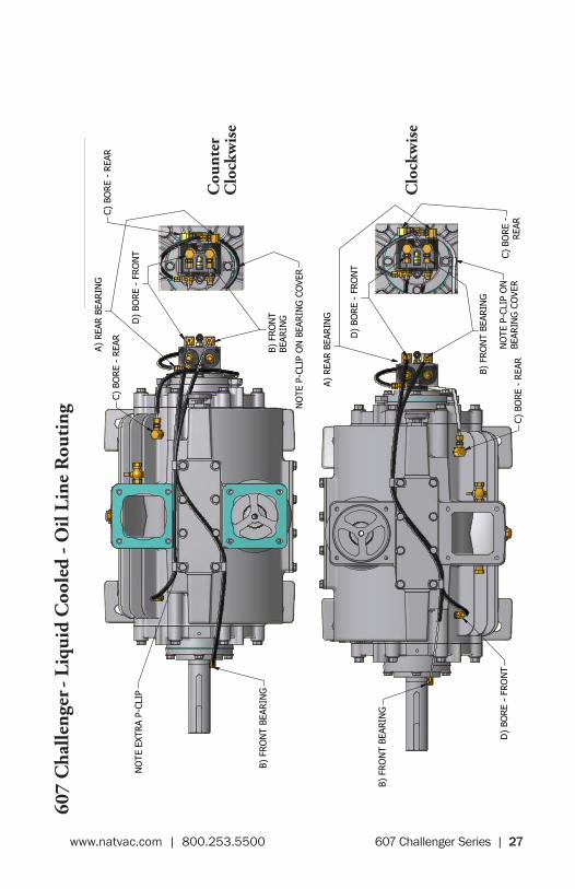
Cou
nter
C
lock
wis
e
Clo
ckw
ise
607 Challenger Series | 27www.natvac.com | 800.253.5500
607
Cha
lleng
er -
Liqu
id C
oole
d - O
il Li
ne R
outi
ng
SECT
ION
B-B
SCAL
E 1/
4
SECT
ION
D-D
SCAL
E 1
/ 4
SECT
ION
E-E
SCAL
E 1
/ 4
MO
UN
TIN
G H
OLE
LO
CATI
ON
SVI
EW F
-FSC
ALE
1 /
4
1 1
2 2
3 3
4 4
5 5
6 6
7 7
8 8
AA
BB
CC
DD
NVE
Nat
iona
lVa
cuum
Eq
uipm
ent,
Inc
.26
70 A
ero
Park
Driv
e, T
rave
rse
City
, MI
4968
6Ph
one:
(23
1) 9
41-0
215
F
ax:
(231
) 94
1-23
54
TO
LE
RA
NC
ES
UN
LE
SS
OT
HE
R W
ISE
SP
EC
IFIE
D
On
e p
lace
(.X
)
±.1
Tw
o p
lace
s (.
XX
)
±.0
3T
hre
e p
lace
s (.
XX
X)
±.01
5A
ng
les
±1°
All
mac
hin
ed s
urf
aces
125
RM
S m
ax.
Rem
ove
all
bu
rrs
and
sh
arp
ed
ges
.C
AD
dra
win
g -
NO
man
ual
ch
ang
es.
All
dim
ensi
on
s in
inch
es u
nle
ss s
pec
ifie
d.
Th
is d
ocu
men
t m
ay c
on
tain
co
nfi
den
tial
tra
de
secr
et in
form
atio
n w
hic
h is
th
e ex
clu
sive
pro
per
ty o
f N
atio
nal
Vac
uu
m E
qu
ipm
ent.
An
yin
form
atio
n o
n t
his
dra
win
g is
no
t to
be
dis
clo
sed
to
an
yon
e n
ot
hav
ing
a "
Nee
d t
oK
no
w."
Th
e in
form
atio
n c
on
tain
ed h
erei
n is
to
be
use
d o
nly
in a
cco
rdan
ce w
ith
th
e b
est
inte
rest
s o
f N
atio
nal
Vac
uu
m E
qu
ipm
ent.
PA
RT
NA
ME
:
607
LIQ
CO
OLE
D C
HAL
LEN
GER
MA
TE
RIA
L:
DR
AW
N B
Y:
SC
AL
E:
CH
EC
KE
D B
Y:
DA
TE
:
RP
TB
OB
PA
RT
NO
.S
HE
ET
2 10
0-60
7-L
(D &
S)
2 o
f1:4SE
E B
OM
APPR
OX.
WT.
CAD
FIL
E LO
CATI
ON
: P:
\Dat
a\CA
D -
Pro
duct
ion\
100-
607-
LD &
S.id
w
SHEE
T SI
ZED
B B
DD
EE
F
F
REV
ISIO
N H
ISTO
RY
REV
DAT
ED
ESCR
IPTI
ON
APPR
OVE
DZO
NE
E4/
28/2
010
UPD
ATE
OIL
PU
MP
GU
ARD
ECN
112
6-
F9/
8/20
10U
PDAT
ED F
ILTE
R L
ID A
ND
OP
BEAR
ING
CO
VER
ECN
115
5-
G10
/22/
2010
REM
OVE
D D
IMS
FOR E
ND
PLAT
E PI
LOT
8.49
8 SH
T 2
ECN
117
9A4 C7
D)
BORE
- FR
ON
T
D)
BORE
- FR
ON
T
B) F
RO
NT
BEAR
ING
(8.1
52)
(1.
499)
(.37
5)
(23.
857)
7.
250
B.C.
1/2-
13 U
NC
- 2B
1.00
0 D
EEP
A) R
EAR B
EARIN
G
3" F
NPT
3/4"
FN
PT3/
4" F
NPT
(7.7
50)
(4.0
63)
4.06
3
(8.1
52)
(28.
918)
(28.
940)
(14.
725)
(14.
725)
(7.7
50)
(23.
857)
(4.0
00)
(18.
797)
(4.0
00)
(18.
797)
3" F
NPT
( 1.
499)
(.37
5)
(.37
5)
(.37
5)
7.
250
B.C.
1/2-
13 U
NC
- 2B
1.00
0 D
EEP
B) F
RO
NT
BEAR
ING
B) F
RO
NT
BEAR
ING
A) R
EAR B
EARIN
G
D)
BORE
- FR
ON
T
B) F
RO
NT
BEAR
ING
100-
607-
LD (
CLO
CKW
ISE)
100-
607-
LS (
COU
NTE
R C
LOCK
WIS
E)
OIL
LIN
E RO
UTI
NG
: 10
0-60
7-LD
DES
IGN
ATIO
ND
ESCR
IPTI
ON
TYPE
PART
NU
MBE
RLE
NG
TH (
IN)
AR. BE
ARIN
GO
IL L
INE
PRO
TECT
OR
320-
407-
001-
607L
D1
320-
409-
002-
607L
D1
7.25
5.25
B F.
BEA
RIN
GO
IL L
INE
PRO
TECT
OR
320-
407-
001-
607L
D2
320-
409-
002-
607L
D2
30.2
528
.25
CBO
RE
- REA
RO
IL L
INE
PRO
TECT
OR
320-
407-
001-
607L
D3
320-
409-
002-
607L
D3
11.0
09.
00
DBO
RE
- FR
ON
TO
IL L
INE
PRO
TECT
OR
320-
407-
001-
607L
D4
320-
409-
002-
607L
D4
25.5
023
.50
OIL
LIN
E RO
UTI
NG
: 10
0-60
7-LS
DES
IGN
ATIO
ND
ESCR
IPTI
ON
TYPE
PART
NU
MBE
RLE
NG
TH (
IN)
AR. B
EARIN
GO
IL L
INE
PRO
TECT
OR
320-
407-
001-
607L
S132
0-40
9-00
2-60
7LS1
7.25
5.25
BF.
BEA
RIN
GO
IL L
INE
PRO
TECT
OR
320-
407-
001-
607L
S232
0-40
9-00
2-60
7LS2
31.2
529
.25
CBO
RE
- REA
RO
IL L
INE
PRO
TECT
OR
320-
407-
001-
607L
S332
0-40
9-00
2-60
7LS3
15.0
013
.00
DBO
RE
- FR
ON
TO
IL L
INE
PRO
TECT
OR
320-
407-
001-
607L
S432
0-40
9-00
2-60
7LS4
25.5
023
.50
NO
TE E
XTRA
P-CL
IP
NO
TE P
-CLI
P O
NBE
ARIN
G C
OVE
R
NO
TE P
-CLI
P O
N B
EARIN
G C
OVE
R
C) B
ORE
-REA
RC)
BO
RE
- REA
R
C) B
ORE
- REA
RC)
BO
RE
- REA
R
(11.
032)
(11.
500)
(5.5
16)
(5.7
50)
(8.9
85)
(13.
375)
(13.
500)
(8.9
22)
.6
88
SECT
ION
B-B
SCAL
E 1/
4
SECT
ION
D-D
SCAL
E 1
/ 4
SECT
ION
E-E
SCAL
E 1
/ 4
MO
UN
TIN
G H
OLE
LO
CATI
ON
SVI
EW F
-FSC
ALE
1 /
4
1 1
2 2
3 3
4 4
5 5
6 6
7 7
8 8
AA
BB
CC
DD
NVE
Nat
iona
lVa
cuum
Eq
uipm
ent,
Inc
.26
70 A
ero
Park
Driv
e, T
rave
rse
City
, MI
4968
6Ph
one:
(23
1) 9
41-0
215
F
ax:
(231
) 94
1-23
54
TO
LE
RA
NC
ES
UN
LE
SS
OT
HE
R W
ISE
SP
EC
IFIE
D
On
e p
lace
(.X
)
±.1
Tw
o p
lace
s (.
XX
)
±.0
3T
hre
e p
lace
s (.
XX
X)
±.01
5A
ng
les
±1°
All
mac
hin
ed s
urf
aces
125
RM
S m
ax.
Rem
ove
all
bu
rrs
and
sh
arp
ed
ges
.C
AD
dra
win
g -
NO
man
ual
ch
ang
es.
All
dim
ensi
on
s in
inch
es u
nle
ss s
pec
ifie
d.
Th
is d
ocu
men
t m
ay c
on
tain
co
nfi
den
tial
tra
de
secr
et in
form
atio
n w
hic
h is
th
e ex
clu
sive
pro
per
ty o
f N
atio
nal
Vac
uu
m E
qu
ipm
ent.
An
yin
form
atio
n o
n t
his
dra
win
g is
no
t to
be
dis
clo
sed
to
an
yon
e n
ot
hav
ing
a "
Nee
d t
oK
no
w."
Th
e in
form
atio
n c
on
tain
ed h
erei
n is
to
be
use
d o
nly
in a
cco
rdan
ce w
ith
th
e b
est
inte
rest
s o
f N
atio
nal
Vac
uu
m E
qu
ipm
ent.
PA
RT
NA
ME
:
607
LIQ
CO
OLE
D C
HAL
LEN
GER
MA
TE
RIA
L:
DR
AW
N B
Y:
SC
AL
E:
CH
EC
KE
D B
Y:
DA
TE
:
RP
TB
OB
PA
RT
NO
.S
HE
ET
2 10
0-60
7-L
(D &
S)
2 o
f1:4SE
E B
OM
APPR
OX.
WT.
CAD
FIL
E LO
CATI
ON
: P:
\Dat
a\CA
D -
Pro
duct
ion\
100-
607-
LD &
S.id
w
SHEE
T SI
ZED
B B
DD
EE
F
F
REV
ISIO
N H
ISTO
RY
REV
DAT
ED
ESCR
IPTI
ON
APPR
OVE
DZO
NE
E4/
28/2
010
UPD
ATE
OIL
PU
MP
GU
ARD
ECN
112
6-
F9/
8/20
10U
PDAT
ED F
ILTE
R L
ID A
ND
OP
BEAR
ING
CO
VER
ECN
115
5-
G10
/22/
2010
REM
OVE
D D
IMS
FOR E
ND
PLAT
E PI
LOT
8.49
8 SH
T 2
ECN
117
9A4 C7
D)
BORE
- FR
ON
T
D)
BORE
- FR
ON
T
B) F
RO
NT
BEAR
ING
(8.1
52)
( 1.
499)
(.37
5)
(23.
857)
7.
250
B.C.
1/2-
13 U
NC
- 2B
1.00
0 D
EEP
A) R
EAR B
EARIN
G
3" F
NPT
3/4"
FN
PT3/
4" F
NPT
(7.7
50)
(4.0
63)
4.06
3
(8.1
52)
(28.
918)
(28.
940)
(14.
725)
(14.
725)
(7.7
50)
(23.
857)
(4.0
00)
(18.
797)
(4.0
00)
(18.
797)
3" F
NPT
( 1.
499)
(.37
5)
(.37
5)
(.37
5)
7.
250
B.C.
1/2-
13 U
NC
- 2B
1.00
0 D
EEP
B) F
RO
NT
BEAR
ING
B) F
RO
NT
BEAR
ING
A) R
EAR B
EARIN
G
D)
BORE
- FR
ON
T
B) F
RO
NT
BEAR
ING
100-
607-
LD (
CLO
CKW
ISE)
100-
607-
LS (
COU
NTE
R C
LOCK
WIS
E)
OIL
LIN
E RO
UTI
NG
: 10
0-60
7-LD
DES
IGN
ATIO
ND
ESCR
IPTI
ON
TYPE
PART
NU
MBE
RLE
NG
TH (
IN)
AR. BE
ARIN
GO
IL L
INE
PRO
TECT
OR
320-
407-
001-
607L
D1
320-
409-
002-
607L
D1
7.25
5.25
B F.
BEA
RIN
GO
IL L
INE
PRO
TECT
OR
320-
407-
001-
607L
D2
320-
409-
002-
607L
D2
30.2
528
.25
CBO
RE
- REA
RO
IL L
INE
PRO
TECT
OR
320-
407-
001-
607L
D3
320-
409-
002-
607L
D3
11.0
09.
00
DBO
RE
- FR
ON
TO
IL L
INE
PRO
TECT
OR
320-
407-
001-
607L
D4
320-
409-
002-
607L
D4
25.5
023
.50
OIL
LIN
E RO
UTI
NG
: 10
0-60
7-LS
DES
IGN
ATIO
ND
ESCR
IPTI
ON
TYPE
PART
NU
MBE
RLE
NG
TH (
IN)
AR. B
EARIN
GO
IL L
INE
PRO
TECT
OR
320-
407-
001-
607L
S132
0-40
9-00
2-60
7LS1
7.25
5.25
BF.
BEA
RIN
GO
IL L
INE
PRO
TECT
OR
320-
407-
001-
607L
S232
0-40
9-00
2-60
7LS2
31.2
529
.25
CBO
RE
- REA
RO
IL L
INE
PRO
TECT
OR
320-
407-
001-
607L
S332
0-40
9-00
2-60
7LS3
15.0
013
.00
DBO
RE
- FR
ON
TO
IL L
INE
PRO
TECT
OR
320-
407-
001-
607L
S432
0-40
9-00
2-60
7LS4
25.5
023
.50
NO
TE E
XTRA
P-CL
IP
NO
TE P
-CLI
P O
NBE
ARIN
G C
OVE
R
NO
TE P
-CLI
P O
N B
EARIN
G C
OVE
R
C) B
ORE
-REA
RC)
BO
RE
- REA
R
C) B
ORE
- REA
RC)
BO
RE
- REA
R
(11.
032)
(11.
500)
(5.5
16)
(5.7
50)
(8.9
85)
(13.
375)
(13.
500)
(8.9
22)
.6
88 Cou
nter
C
lock
wis
e
Clo
ckw
ise

28 | 607 Challenger Series www.natvac.com | 800.253.5500
Detail - Key # 26
Automatic Oil Pump
Three Outlet Type
Part # 320 - LW32AD ClockwisePart # 320 - LW32AS Counterclockwise
See Parts Diagram Opposite.
Parts List – Automatic Oil Pump
Part # Description
320-P3CW Pump Body (Clockwise)320-P3CCW Pump Body (Counterclockwise)320-P5 Driven Gear (Clockwise)320-PA5 Driven Gear (Counterclockwise)320-P6 Spring320-P7 Driving Gear (Clockwise)320-P7CCW Driving Gear (Counterclockwise)320-P8 Seal320-P9 Plug320-P10 Retainer320-P11 Adjusting Screw320-P12 Gasket320-P13 Lid320-P14 Screw320-P15 Jam Nut320-P16 Cap*
*
National Vacuum Equipment | 800.253.5500 | www.natvac.com
* CW WormCCW Worm
L on 3 Port CW R on 3 Port CW
L on 3 Port CCW R on 3 Port CCW
2 PortSide
1 PortSide
2 PortSide
1 PortSide
320-P5 and 320-PA5 Details

607 Challenger Series | 29www.natvac.com | 800.253.5500
Detail - Key # 26
Automatic Oil Pump
Three Outlet Type
Part # 320 - LW32AD ClockwisePart # 320 - LW32AS Counterclockwise
See Parts Diagram Opposite.
Parts List – Automatic Oil Pump
Part # Description
320-P3CW Pump Body (Clockwise)320-P3CCW Pump Body (Counterclockwise)320-P5 Driven Gear (Clockwise)320-PA5 Driven Gear (Counterclockwise)320-P6 Spring320-P7 Driving Gear (Clockwise)320-P7CCW Driving Gear (Counterclockwise)320-P8 Seal320-P9 Plug320-P10 Retainer320-P11 Adjusting Screw320-P12 Gasket320-P13 Lid320-P14 Screw320-P15 Jam Nut320-P16 Cap*
*
National Vacuum Equipment | 800.253.5500 | www.natvac.com
* CW WormCCW Worm
L on 3 Port CW R on 3 Port CW
L on 3 Port CCW R on 3 Port CCW
2 PortSide
1 PortSide
2 PortSide
1 PortSide
320-P5 and 320-PA5 Details

30 | 607 Challenger Series www.natvac.com | 800.253.5500
Detail - Key # 26
Automatic Oil PumpFour Outlet Type
Part # 320 - LW32BD ClockwisePart # 320 - LW32BS Counterclockwise
Parts List – Automatic Oil Pump
Part # Description
320-P4CW Pump Body (Clockwise)320-P4CCW Pump Body (Counterclockwise)320-P5 Driven Gear (Clockwise)320-PA5 Driven Gear (Counterclockwise)320-P6 Spring320-P7 Driving Gear (Clockwise)320-P7CCW Driving Gear (Counterclockwise)320-P8 Seal320-P9 Plug320-P10 Retainer320-P11 Adjusting Screw320-P12 Gasket320-P13 Lid320-P14 Screw320-P15 Jam Nut320-P16 Cap*
*
National Vacuum Equipment | 800.253.5500 | www.natvac.com
* CW WormCCW Worm
L and R on 4 Port CW
L and R Gear on 4 Port CCW
2 PortGear
See Parts Diagram Opposite.This oil pump is in all pumps with a Serial # that is 31845 or above.
320-P5 and 320-PA5 Details
2 PortGear

607 Challenger Series | 31www.natvac.com | 800.253.5500
Detail - Key # 26
Automatic Oil PumpFour Outlet Type
Part # 320 - LW32BD ClockwisePart # 320 - LW32BS Counterclockwise
Parts List – Automatic Oil Pump
Part # Description
320-P4CW Pump Body (Clockwise)320-P4CCW Pump Body (Counterclockwise)320-P5 Driven Gear (Clockwise)320-PA5 Driven Gear (Counterclockwise)320-P6 Spring320-P7 Driving Gear (Clockwise)320-P7CCW Driving Gear (Counterclockwise)320-P8 Seal320-P9 Plug320-P10 Retainer320-P11 Adjusting Screw320-P12 Gasket320-P13 Lid320-P14 Screw320-P15 Jam Nut320-P16 Cap*
*
National Vacuum Equipment | 800.253.5500 | www.natvac.com
* CW WormCCW Worm
L and R on 4 Port CW
L and R Gear on 4 Port CCW
2 PortGear
See Parts Diagram Opposite.This oil pump is in all pumps with a Serial # that is 31845 or above.
320-P5 and 320-PA5 Details
2 PortGear

32 | 607 Challenger Series www.natvac.com | 800.253.5500

607 Challenger Series | 33www.natvac.com | 800.253.5500
National Vacuum Equipment
MADEIN USA
Vane Replacement &Complete Rebuild Manual
Challenger Series Rotary Vane Vacuum Pumps
34 | 607 Challenger Series www.natvac.com | 800.253.5500
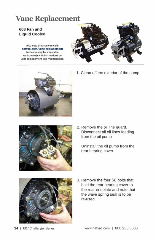
1. Clean off the exterior of the pump
2. Remove the oil line guard. Disconnect all oil lines feeding from the oil pump
Uninstall the oil pump from the rear bearing cover.
3. Remove the four (4) bolts that hold the rear bearing cover to the rear endplate and note that the wave spring seal is to be re-used.
Vane Replacement608 Fan and Liquid Cooled
Also note that you can visit: natvac.com/vane-replacement
to view a step by step video walkthrough with instructions on
vane replacement and maintenance.

607 Challenger Series | 35www.natvac.com | 800.253.5500
4. Remove the oil pump drive key from the end of the rotor.
6. Remove the top two endplate bolts and replace with two (2) 3/8-16 stud/dowels (or de-headed bolts), and then remove the remaining bolts.
5. (Fan Cooled Only) Remove the fan shroud supports connecting the shroud “tin” to the rear endplate.
7. Remove the rear endplate with a gentle “wiggle”, clean gasket surface and remove the vanes for inspection.

36 | 607 Challenger Series www.natvac.com | 800.253.5500
8. Inspect the original vanes for any delamination, chipping or other damage.
If any of the vanes are worn more than 1/4”, are chipped or delaminated they should be replaced.
We highly recommend replacing vanes in sets. Apply a liberal amount of lubricant to the vanes before installing in the rotor slots.
It is always a good idea to have a spare set of replacement vanes on hand to reduce pump downtime.
9. Install one (1) new endplate gasket between the housing and the endplate, do not use any gasket sealer.
Carefully guide the endplate onto the rotor and threaded dowel pins
(Fan Cooled Only) Reinstall the eleven (11) self-tapping screws and holding the fan shroud to the rear end-plate. Fasten the upper fan shroud tin to the fan shroud support on the rear endplate.
607 Challenger Series | 37www.natvac.com | 800.253.5500
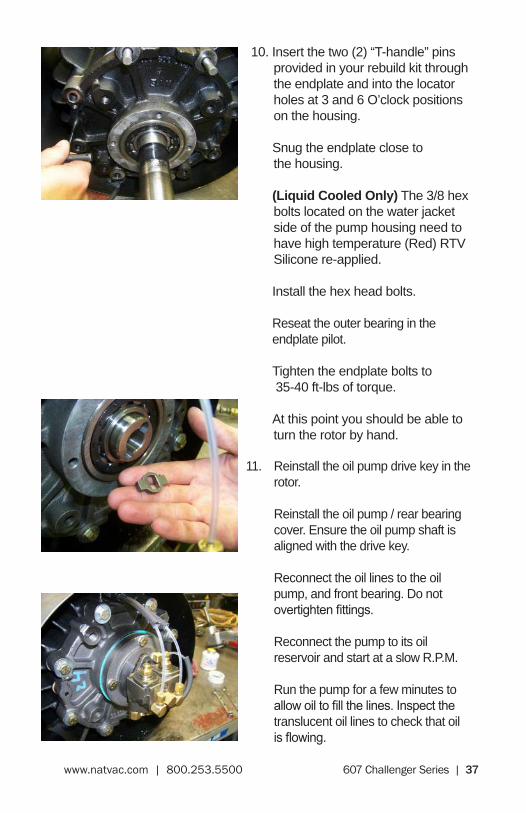
10. Insert the two (2) “T-handle” pins provided in your rebuild kit through the endplate and into the locator holes at 3 and 6 O’clock positions on the housing.
Snug the endplate close to the housing.
(Liquid Cooled Only) The 3/8 hex bolts located on the water jacket side of the pump housing need to have high temperature (Red) RTV Silicone re-applied.
Install the hex head bolts.
Reseat the outer bearing in the endplate pilot.
Tighten the endplate bolts to 35-40 ft-lbs of torque.
At this point you should be able to turn the rotor by hand.
11. Reinstall the oil pump drive key in the rotor.
Reinstall the oil pump / rear bearing cover. Ensure the oil pump shaft is aligned with the drive key.
Reconnect the oil lines to the oil pump, and front bearing. Do not overtightenfittings.
Reconnect the pump to its oil reservoir and start at a slow R.P.M.
Run the pump for a few minutes to allowoiltofillthelines.Inspectthetranslucent oil lines to check that oil isflowing.

38 | 607 Challenger Series www.natvac.com | 800.253.5500
Complete Rebuild608 Fan and Liquid Cooled
1. Clean off the exterior of the pump
2. Remove the oil line guard. Disconnect all oil lines feeding from the oil pump
Uninstall the oil pump from the rear bearing cover.
3. Remove the four (4) bolts that hold the rear bearing cover to the rear endplate and remove the rear bearing cover.
Also note that you can visit: natvac.com/vane-replacement
to view a step by step video walkthrough with instructions on
vane replacement and maintenance.

607 Challenger Series | 39www.natvac.com | 800.253.5500
4. Remove the oil pump drive key from the end of the rotor.
6. Remove the top two (2) bolts that hold the rear endplate to the pump housing and replace with two (2) 3/8-16 threaded dowels. Once in place, remove the lower six (6) 3/8 hex bolts.
5. (Fan Cooled Only) Remove the eleven (11) self-tapping screws that fasten the fan shroud “tin” to the pump. Remove the fan shroud support connecting the fan shroud “tin” to the rear endplate.
7. Remove the rear endplate, gasket, and vanes.
40 | 607 Challenger Series www.natvac.com | 800.253.5500
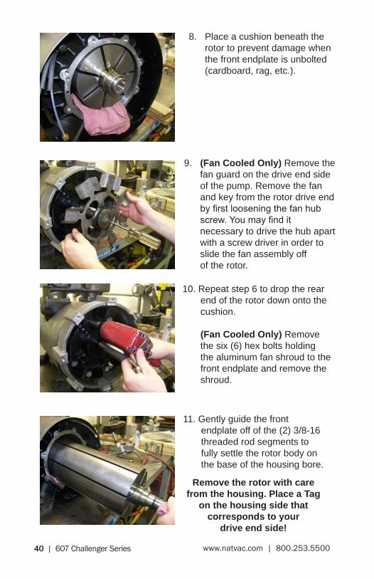
8. Place a cushion beneath the rotor to prevent damage when the front endplate is unbolted (cardboard, rag, etc.).
9. (Fan Cooled Only) Remove the fan guard on the drive end side of the pump. Remove the fan and key from the rotor drive end byfirstlooseningthefanhubscrew.Youmayfindit necessary to drive the hub apart with a screw driver in order to slide the fan assembly off of the rotor.
10. Repeat step 6 to drop the rear end of the rotor down onto the cushion.
(Fan Cooled Only) Remove the six (6) hex bolts holding the aluminum fan shroud to the front endplate and remove the shroud.
11. Gently guide the front endplate off of the (2) 3/8-16 threaded rod segments to fully settle the rotor body on the base of the housing bore.
Remove the rotor with care from the housing. Place a Tag
on the housing side that corresponds to your
drive end side!

607 Challenger Series | 41www.natvac.com | 800.253.5500
12. Remove the four-way assembly, gaskets, and check valve assembly. Carefully turn the housing upside down so that the pump feet are facing the ceiling.
13. Inspect the housing for wear or damage. If the housing needs to be bored or honed, remove only as much material as is necessary to give a smooth clean bore.
The maximum overbore we recommend is 0.060 inches. A new housing has a bore of 7.875 inches.
If you bore or hone the housing, remove all connected accessories, including the fan shroud, 4-way valve, gaskets, etc.
14. Clean the housing of any debris and apply a liberal amount of lubrication to the housing bore.
15. (Optional) If there is damage evident to the bearings, they will need to be replaced. Once the rotor is removed, start by cutting off the old bearing inner race on both ends of the rotor. Be sure to line up the cutting wheel with one of the vane slots so as not to damage the rotor or seal sleeve.

42 | 607 Challenger Series www.natvac.com | 800.253.5500
16. Clean the rotor and rotor slots and inspect the rotor for wear or damage.
Place the clean rotor inside the housing with the drive end in the same orientation it originally was. This will be the side you tagged in step 11 of this procedure.
17. (Continuation of Step 15)Remove the two (2) inner races from the replacement bearings provided in your repair kit.
Place the inner races onto a hot plate and get them hot. Do not leave them on the plate so long that they become discolored.
Use a welding glove to take the hot inner race from the hot plate and slide it onto the rotor shaft.
The bearing race shoulder should be tight against the seal sleeve.
Install on both sides of the rotor.
Allow ample time for the inner races to cool and set onto the rotor before continuing.

607 Challenger Series | 43www.natvac.com | 800.253.5500
19. Shift the housing so that the intake (Square port) is hanging slightly off of the rebuild work surface.
Place one of the 0.007” shims between the rotor and rotor bore so that the shim is within the housing and will not interfere with the endplate when they are reinstalled.
Divert the pull wire into the housing cavity and out through the intake port.
Repeat for both ends of the rotor.
18. Inspect the original vanes for any delamination, chipping or other damage.
Anewvaneisflushwiththeoutside diameter of the rotor.
If any of the vanes are worn more than 1/4”, chipped or delaminated they should be replaced.
We highly recommend replacing vanes in sets. Apply a liberal amount of lubricant to the vanes before installing in the rotor slots.
It is always a good idea to have a spare set of replacement vanes on hand to reduce pump downtime.

44 | 607 Challenger Series www.natvac.com | 800.253.5500
20. Remove the seals from the endplates. Inspect for damage, the seals should be soft and pliable.
Clean the endplate as needed. Apply new lubricant along the seal pilot in each of the endplates.
The seals need to be installed back to back. The faces without the oil groove should be touching.
We recommend using a seal driver tool to properly seat the seals in the endplate. Drive the seals into the endplate.
Repeat for both endplates.
22. Install two (2) 3/8-16 threaded dowels so that they can support the weight of the endplate for installation.
Install one (1) new endplate gasket between the housing and the endplate, do not use any gasket sealer.
Carefully guide the endplate onto the rotor and threaded rod segments
21. Lubricate the roller bearing pilot in the endplate. Using a bearing driver, seat the roller bearing into the endplate.
Repeat for both endplates.

607 Challenger Series | 45www.natvac.com | 800.253.5500
23. Insert one (1) of the dowel pin “T-handles” into either of the dowel pin holes on the endplate through into the housing.
Snug the endplate close to the housing and install the 3/8 hex head bolts.
(Liquid Cooled Only) The 3/8 hex bolts located on the waterjacket side of the pump housing need to have high temperature (Red) RTV Silicone re-applied.
Tighten the endplate bolts to 35-40 ft-lbs of torque.
Repeat the process for the opposite endplate, but make sure to install the “T-handle” dowel pin on the same side of the housing as the other endplate, so as to prevent the rotor from twisting when the endplates are fully bolted into place
Rotate the housing right side up again, so the pump feet are on the work station.
24. Grasp the shim pull wires hanging out of the inlet, and gently pull to remove the 0.007” shims.
You may need to rotate your pump and pull the wires simultaneously to get them to release.
25. Reinstall the bearing cover gaskets, lubricate along the rotor bearing cover interface, reinstall the bearing covers (with wave washers installed)
46 | 607 Challenger Series www.natvac.com | 800.253.5500
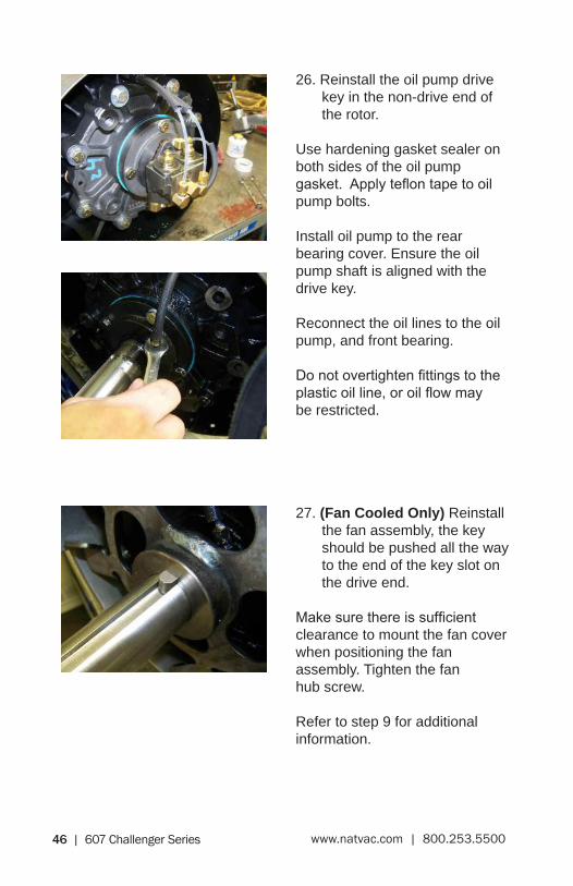
27. (Fan Cooled Only) Reinstall the fan assembly, the key should be pushed all the way to the end of the key slot on the drive end.
Makesurethereissufficientclearance to mount the fan cover when positioning the fan assembly. Tighten the fan hub screw.
Refer to step 9 for additional information.
26. Reinstall the oil pump drive key in the non-drive end of the rotor.
Use hardening gasket sealer on both sides of the oil pump gasket.Applyteflontapetooilpump bolts.
Install oil pump to the rear bearing cover. Ensure the oil pump shaft is aligned with the drive key.
Reconnect the oil lines to the oil pump, and front bearing.
Donotovertightenfittingstotheplasticoilline,oroilflowmay be restricted.

607 Challenger Series | 47www.natvac.com | 800.253.5500
28. Install two (2) four-way gaskets to the housing interface.
Reinstall the four way manifold, making sure to line up the square port on the housing with the square port on the four way manifold.
Replace any gaskets / O-rings as needed.
29. We highly recommend pressure testing your pump for leaks before putting it to work. We test our pumps at 20 psi of pressure.
Put a 3” Male NPT plug in the exhaust port and a similar adapter that can connect to a controlled pressurized air supply in the inlet.
Spraying your pump with soapy water while pressurized will expose any bubbling air leaks in your vacuum pump.
30. Reconnect the pump to its oil reservoir and start at a slow R.P.M.
Run the pump for a few minutestoallowoiltofillthelines. Inspect the translucent oil linestocheckthatoilisflowing.
The pump is now ready to go to work!
48 | 607 Challenger Series www.natvac.com | 800.253.5500
P.O. Box 685Traverse City, MI 49685 USA
231.941.0215 Phone231.941.2354 Fax
National Vacuum Equipment, Inc.