owner’s guide model 3203 - produktkatalogepdf.ampire.de/viper_le.pdf · congratulations...
TRANSCRIPT

O W N E R’ S G U I D E M O D E L
3203
© 2009 Directed Electronics. All rights reserved. G3203V 2009-11
The company behind Viper® Auto Security Systems
is Directed Electronics.
Since its inception, Directed Electronics has had one
purpose, to provide consumers with the finest vehicle
security and car stereo products and accessories
available. The recipient of nearly 100 patents and
Innovations Awards in the field of advanced electronic
technology, Directed Electronics is ISO 9001 registered.
Quality Directed Electronics products are sold and serviced
throughout North America and around the world.
Call (800) 876-0800 for more information about our
products and ser vic es.
Vista, CA 92081www.viper.com
Directed Electronics is an ISO 9001 registered company.
Directed Electronics is committed to delivering world class quality products and services that excite and delight our customers.
NO ONE DARES COME CLOSE
Congratulations Congratulations on the purchase of your state-of-the-art security system. Reading this owner’s guide prior to using your system will help maxi-mize the use of your system and its many features. For more informa-tion please visit the below website:
http://www.viper.com – For general and additional guide infor-mation.
For any additional questions please contact your authorized Directed dealer or contact Directed at 1-800-753-0600.
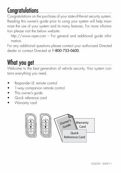
What you getWelcome to the best generation of vehicle security. Your system con-tains everything you need.
Responder LE remote control1-way companion remote controlThis owner’s guideQuick reference cardWarranty card
AUX AUX
Warranty Card
Owner’s
Guide
QuickReference Card
G3203V 2009-11

Important information
Your WarrantyYour system comes with a warranty. Please make sure you receive the warranty registration card and proof of purchase from your dealer indicating the product was installed by an authorized Directed dealer. Your product warranty must be validated within 10 days of purchase. You can validate it online at www.prodregister.com/directed or com-plete and return the warranty registration card.
Quick Reference CardCarry this card with you to reference your system’s many features.
Replacement Remote ControlsIf additional remote controls are desired, please see your authorized dealer or visit us at www.directedstore.com to order. Part numbers are: 7251V for Responder LE 2-way remote control and 7153V for the 1-way companion remote control.

Contents
Getting Started .................................................................................................... 3Keys to using this manual ...................................................................... 3
Responder LE 2-Way ........................................................................................... 4Using your System ............................................................................................... 6
Commands and Confirmations .............................................................. 6Performing Commands ......................................................................... 6Remote Control Command table ............................................................ 7
Basic Commands (Direct Access) .......................................................................... 8Arm ................................................................................................... 8Disarm ............................................................................................... 8Remote Start /AUX1/AUX4 .................................................................. 9AUX/Trunk .......................................................................................... 9
Advanced Commands: (Level 1) ......................................................................... 10Silent Arm ......................................................................................... 10AUX 1 .............................................................................................. 10
Advanced Commands: (Level 2) ......................................................................... 11Sensor Bypass ................................................................................... 11Remote Valet .................................................................................... 11AUX 2 .............................................................................................. 12Arm Status ........................................................................................ 12
Advanced Commands: (Level 3) ......................................................................... 13Sensor Silent Arm* ............................................................................ 13AUX 3 .............................................................................................. 13
Advanced Commands: (Level 4) ......................................................................... 14Full Silent Arm* ................................................................................. 14AUX 4 .............................................................................................. 14
Remote Control Configuration ............................................................................ 15Remote Programming ......................................................................... 15Pairing a 1-way or 2-way remote control ............................................. 15Remote Features ............................................................................... 16Car 2 ............................................................................................... 18Remote Beep ..................................................................................... 19Sensor Adjust .................................................................................... 19
Alarm Features ................................................................................................. 20Normal Arm Protection ....................................................................... 20Sensor Silent Arm protection ............................................................... 20Full Silent Arm Protection .................................................................... 21Sensor Warn-away ........................................................................... 21Full Trigger ........................................................................................ 21Emergency Override .......................................................................... 21

Trigger Zone Fault Report.................................................................... 22Alarm Report ..................................................................................... 22Nuisance Prevention (NPC) ................................................................. 23
Remote and System Operations .......................................................................... 24Passive Arming* ................................................................................ 24Auto Re-arming* ................................................................................ 24Valet Mode ....................................................................................... 25Power Save ....................................................................................... 25Rapid Resume ................................................................................... 25Automatic Remote Updates ................................................................. 25Out of Range .................................................................................... 26No Remote Output ............................................................................. 26Car Select ......................................................................................... 26Vehicle Recovery System (VRS) ............................................................ 27
System Expansion Options ................................................................................. 28Battery Information ............................................................................................ 30
Low Battery ....................................................................................... 30Battery Life ........................................................................................ 30Battery Disposal ................................................................................ 32
Glossary of Terms .............................................................................................. 33Government Regulations .................................................................................... 34Additional Information ....................................................................................... 35
Interference ....................................................................................... 35Upgrades ......................................................................................... 35Water/Heat Resistance ...................................................................... 35
Limited lifetime consumer warranty ..................................................................... 36

3© 2009 Directed Electronics. All rights reserved.
Getting Started
Keys to using this manualSpecific actions (in bold type) and style conventions are used consis-tently throughout this manual, they are as follows:
Press: implies pushing in and releasing a button.Hold: is used after “press” actions when a button needs to be held in position for an extended period of time, typically several seconds.Italicized words denote section/sub headings in this guide and can be located through the table of contents.An asterisk (*) when used after a word or phrase denotes that additional details can be found in related sections usually noted at the bottom of the page or end of the section.Ghost LED’s are identified by the command/function button they are associated with.

4 © 2009 Directed Electronics. All rights reserved.
Responder LE 2-Way
TransmitLED
InternalAntenna
GhostLED’s
CommandButtons
FunctionButton
AUX
Feature Description
Internal Antenna Used for transmitting and receiving* information
Command Buttons (4) Used to perform arming, disarming, and auxiliary channel commands.
Function Button Used to access function levels for commands, configuration menus for programming, and car selection.
Ghost LED’s ** Each button has an associated LED next to it that are active during related operations. These LED’s are labeled respec-tively as:
arm LED, disarm LED, rs/aux LED, aux LED, and LED
* 2-way communication is only applicable to the Responder LE remote control
** Term denotes that these LED’s are only visible when on (Ghost LED’s are only applicable to the Responder LE remote control).

5© 2009 Directed Electronics. All rights reserved.
Control Center
Control CenterButton
Control Center LED
The control center, typically located on the upper part of the front windshield sends and receives commands or messages to and from your system. It consists of:
The In-vehicle system antenna, for 2 way communication. The control center LED, as a visual indicator of the system’s sta-tus. The control center button, for placing the system into valet mode* and to perform the emergency override** operation.
* See Remote and System Operations section for details.** See Alarm Features for details.

6 © 2009 Directed Electronics. All rights reserved.
Using your System
Commands and ConfirmationsCommands, basic or advanced, are used to activate system features and are performed by pressing one of the command buttons. Ba-sic commands control the most often used security features while ad-vanced commands control more specialized features.
Confirmations for basic or advanced commands are indicated first by siren chirps and parking light flashes, and then by illuminated Ghost LED’s and beeps or tones on the remote control. A description of each feature confirmation is found in the Basic Commands and Advanced Commands sections.
Performing CommandsPerform basic commands by pressing a command button (Ghost LED’s are off).Perform advanced commands by first accessing Levels 1-4 using the
button and then by pressing a command button while within a Level (Levels are indicated by illuminated ghost LED’s after pressing
button).
Advanced Command example: Silent ArmPress1. the button once to access function level 1, the LED turns on.Press2. the button while the LED is still on to perform the silent arm command.The Arm LED will illuminate to confirm when the silent arm mes-3. sage from the system is received.

7© 2009 Directed Electronics. All rights reserved.
Remote Control Command table
Button
Level Direct Access x 1
LEVEL 1
x 2
LEVEL 2
x 3
LEVEL 3
x 4
LEVEL 4
Arm/Lock
(Panic)
Silent Arm Sensor
Bypass
Sensor Silent
Arm
Full Silent
Arm
Disarm/Unlock Silent Disarm Remote Valet Car Finder
Remote Start*/
Aux 1/4**
AUX Aux/Trunk AUX 1 AUX 2 AUX 3 AUX 4
Advance Level,
Change Car
(3 sec), Enter
programming
(8 sec)
Arm
Status ***
* Available only with optional remote start module installation** This button can command either aux 1 or aux 4 if turned on by
an authorized Directed dealer.*** Not available for the 1-way companion remote control.
8 © 2009 Directed Electronics. All rights reserved.
Basic Commands (Direct Access)No ghost LED’s on
ArmPress and release
The alarm arms, doors lock (if connected), and the siren chirps and parking lights flash once. The arm LED and beeps play to confirm. If valet mode* is on, the doors lock and the arm LED, LED and a fault tone plays. Exit valet mode to arm the alarm normally.
If a trigger zone fault is detected the siren chirps once again and the remote will emit a trigger zone fault report**, the arm LED, LED and a fault tone plays.
To Arm and PanicPress and hold The alarm arms (or locks in valet) and, after 2 seconds, sounds the siren and flashes the parking lights. The ghost LED’s flash and siren tones play to confirm. Press the or button to stop the output.
DisarmPress and release
The alarm disarms, doors unlock (if connected), and the siren chirps and parking lights flash twice. The disarm LED and beeps play to confirm. If valet mode* is on, the doors unlock and the disarm LED,
LED and fault tones play.

9© 2009 Directed Electronics. All rights reserved.
An alarm report** will replace the disarm output if the alarm was trig-gered; the siren will chirp 4 or 5 times, and the disarm LED, LED and 4 or 5 fault tones play to alert of the report.
Remote Start /AUX1/AUX4Press and release
Remote Start***Activates (or if on, deactivates) the remote starter. The engine and parking lights turn on or off accordingly. The rs/aux LED and on tones play, or the rs/aux LED and off tones play to confirm.
AUX1/AUX4****Activates (or if on, deactivates) the aux 1or aux 4 output. The aux LED and on tones or off tones play to confirm.
AUX/TrunkPress and hold AUX
The Trunk opens (if connected) when this button is pressed for 2 sec-onds. The Aux LED and tones play to confirm.
* See Remote and System Operations for details.** See Alarm Features for details.*** Available only with optional Remote Start module installation.**** This feature must be turned on by an authorized Directed dealer.

10 © 2009 Directed Electronics. All rights reserved.
Advanced Commands: (Level 1)Press and release the button 1 time. The LED illuminates indicat-ing Level 1Note: The transmit LED on the 1-way remote will flash in groups of 1 to indicate level 1.
Silent ArmPress and release
The alarm arms, doors lock (if connected), and the parking lights flash once. The arm LED turns on to confirm. valet mode* or trigger zone fault report** messages may be received.
Silent DisarmPress and release
The alarm disarms, doors unlock (if connected), and the parking lights flash twice. The disarm LED turns on to confirm. The silent disarm out-put may be replaced by the alarm report**.
AUX 1Press and release AUX
Activates (or if on, deactivates) the aux 1 output. The aux LED and on tones or off tones play to confirm.
* See Remote and System Operations section for details.** See Alarm Features for details.
11© 2009 Directed Electronics. All rights reserved.
Advanced Commands: (Level 2)Press and release the button 2 times. The and aux LED’s illumi-nate indicating Level 2Note: The transmit LED on the 1-way remote will flash in groups of 2 to indicate level 2.
Sensor BypassPress and release
Performing the sensor bypass command will incrementally bypass sen-sor operations and be confirmed as follows:
Warn-away Bypass: The parking lights flash 2 times. The arm LED, 1 beep and 1 fault tone play to confirm. Sensors will be activated for full trigger levels of impact only.Warn-away & Full Trigger Bypass: The parking lights flash 3 times. The arm LED, 1 beep and 2 fault tones play to confirm. Sensors will not be activated for any level of impact.Sensor Bypass Off: The parking lights flash 1 time. The arm LED and 1 beep play to confirm. Sensors are fully operational.
Note Sensor bypass can only be performed when the system is armed. The LED and a long fault tone plays as an alert when performing sensor bypass when the system is disarmed. Perform arm command any time to turn sensor bypass off.
Remote Valet Press and release
Enters (or if on, exits) valet mode. The control center LED turns on and
12 © 2009 Directed Electronics. All rights reserved.
off accordingly. The disarm LED and valet beeps play (1 for on, 2 for off) to confirm.
AUX 2Press and release AUX
Activates (or if on, deactivates) the aux 2 output. The aux LED and on tones or off tones play to confirm.
Arm StatusPress and hold the button
The remote will generate an output to display the systems arm status since its last update message or command operation. It will report status via ghost LED’s, beeps, and tones as described in this section for arm, disarm, valet mode arm, valet mode disarm, sensor silent arm, full silent arm.

13© 2009 Directed Electronics. All rights reserved.
Advanced Commands: (Level 3)Press and release the button 3 times. The , aux and rs/auxLED’s illuminate indicating Level 3.Note: The transmit LED on the 1-way remote will flash in groups of 3 to indicate level 3.
Sensor Silent Arm*Press and release
The alarm arms, doors lock, and the siren chirps and parking lights flash 3 times. The arm LED, 1 beep and 3 fault tones play to con-firm.
Car finderPress and release
The siren emits one long chirp and the parking lights flash for 10 sec-onds. The disarm LED and 1 beep play to confirm. The parking light flashes stop if armed or disarmed while car finder is in progress.
AUX 3Press and release AUX
Activates (or if on, deactivates) the aux 3 output. The aux LED and on tones or off tones play to confirm.
* See Alarm Features for more details.

14 © 2009 Directed Electronics. All rights reserved.
Advanced Commands: (Level 4)Press and release the button 4 times. The , aux, rs/aux and disarm LED’s illuminate indicating Level 4Note: The transmit LED on the 1-way remote will flash in groups of 4 to indicate level 4.
Full Silent Arm*Press and release
The alarm arms, doors lock, and the siren chirps and parking lights flash 4 times. The arm LED, 1 beep and 4 fault tones play to con-firm.
AUX 4Press and release AUX
Activates (or if on, deactivates) the aux 4 output. The aux LED and on tones or off tones play to confirm.
* See Alarm Features for more details.

15© 2009 Directed Electronics. All rights reserved.
Remote Control Configuration
Remote ProgrammingThe Responder LE and 1-way companion remote controls have opera-tions that can be configured to a user’s personal preferences. The fol-lowing instruction will direct you through the available programming options for both remote controls.
To enter programming, press and hold the button for 8 seconds, the remote emits one long beep and the transmit LED turns on to indi-cate the main menu is accessed.
To exit programming or go back to a previous menu, press and re-lease the button. 1 short and 1 long beep is emitted for each step back and when programming is exited the transmit LED turns off.
Note: The 1-way remote does not emit any confirmation beeps.
Pairing a 1-way or 2-way remote control Note: The remote control may or may not emit sounds during this operation.
Prepare the vehicleOpen1. a door. Turn2. the ignition On. Press3. and release then press and hold the control center button. The control center LED flashes and siren chirps one time to con-firm the system is prepared.Release4. the button and proceed below.
Note: Begin pairing within 60 seconds or the system will exit (indi-cated by a long siren chirp) and need to be prepared again.

16 © 2009 Directed Electronics. All rights reserved.
Prepare the remote controlSelect the desired car 1 (default) or car 2 operation before proceed-ing.
Press1. and hold the button of the remote control for 8 seconds until the transmit LED turns on, and then release it (If programmed to operate two systems, ignore the Transmit LED flashes at 3 sec-onds).Press2. and hold the button until the transmit LED flashes off and on three times. Press3. and hold the button until the siren emits one long chirp to confirm Pairing. Note: 2-way remote controls MUST also emit a sequence of chimes to confirm pairing is successful. If not heard, make sure the system is still prepared and repeat step 3 until successful.
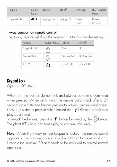
Remote Features Press the button to access the remote operation features, 2 trans-mit LED flashes and 2 beeps indicate the remote features menu is accessed. Press the buttons indicated in the tables below to set the feature option.
Responder LEThe ghost LED’s next to the button indicate the feature settings. Feature Button
PressLED on LED off LED Flash LED Double
Flash
Keypad Lock Auto Off
Remote Beeps Beeps On Beeps Off Triggers only
Car 2 Car 2 On Car 2 Off
17© 2009 Directed Electronics. All rights reserved.
Feature Button Press
LED on LED off LED Flash LED Double Flash
Page Mode AUX Paging On Paging Off Power Save1
Power Save 2
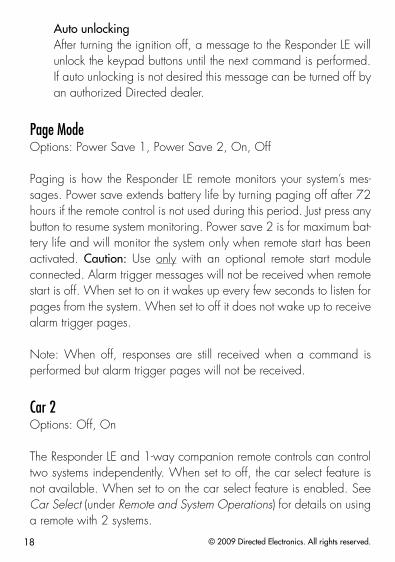
1-way companion remote controlThe 1-way remote will flash the transmit LED to indicate the setting.
Feature Button Press LED on LED off
Keypad Lock Auto Off
No function No function No function
Car 2 Car 2 On Car 2 Off
Keypad LockOptions: Off, Auto
When off, the buttons do not lock and always perform a command when pressed. When set to auto, the remote buttons lock after a 20 second lapse between buttons presses to prevent unintentional opera-tions. If a button is pressed when locked the LED and a fault tone play as an alert. To unlock the buttons, press the button followed by the button. The ghost LEDs flash and tones play to confirm unlocking.
Note: When the 1-way remote keypad is locked, the remote control appears to be non-operational. It will not transmit a command or il-luminate the transmit LED and needs to be unlocked to resume normal operation.
18 © 2009 Directed Electronics. All rights reserved.
Auto unlockingAfter turning the ignition off, a message to the Responder LE will unlock the keypad buttons until the next command is performed. If auto unlocking is not desired this message can be turned off by an authorized Directed dealer.
Page Mode Options: Power Save 1, Power Save 2, On, Off
Paging is how the Responder LE remote monitors your system’s mes-sages. Power save extends battery life by turning paging off after 72 hours if the remote control is not used during this period. Just press any button to resume system monitoring. Power save 2 is for maximum bat-tery life and will monitor the system only when remote start has been activated. Caution: Use only with an optional remote start module connected. Alarm trigger messages will not be received when remote start is off. When set to on it wakes up every few seconds to listen for pages from the system. When set to off it does not wake up to receive alarm trigger pages.
Note: When off, responses are still received when a command is performed but alarm trigger pages will not be received.
Car 2Options: Off, On
The Responder LE and 1-way companion remote controls can control two systems independently. When set to off, the car select feature is not available. When set to on the car select feature is enabled. See Car Select (under Remote and System Operations) for details on using a remote with 2 systems.
19© 2009 Directed Electronics. All rights reserved.
Remote BeepOptions: On, Off, Triggers Only
The Responder LE will emit a beep as confirmation of button presses and command responses. When set to off, beeps are not emitted for any operations except programming. For triggers only, beeps will only be emitted for full trigger messages.
Sensor AdjustThe button is used for sensor adjustment, to avoid unintended alarm triggers; it is recommended that an authorized Directed dealer performs all sensor adjustments.

20 © 2009 Directed Electronics. All rights reserved.
Alarm Features
Normal Arm ProtectionControl center LED: The control center LED flashes as a visual indicator that your vehicle’s security system is active.
Starter Kill: The Failsafe starter kill relay prevents the engine from starting
Note May require additional parts and installation
Sensor triggers: The onboard shock sensor can distinguish minor im-pacts from major impacts to the vehicle exterior. Minor impacts cause the system to emit a Warn-away output by chirping the siren and flashing the parking lights for 3 seconds. Major impacts caused for example by a forcible entry attempt, results in a Full Trigger output. The siren sounds and the parking lights flash for 30 seconds or longer. Full Triggers send a message to the remote control.
Point of entry triggers: Opening the hood or trunk causes a Full Trig-ger output, while opening a Door or turning on the Ignition causes the the siren to chirp 3 seconds before beginning the Full Trigger output. This 3 second delay allows time to disarm and silence the siren in case of accidental trigger. The Full Trigger message is still sent to the remote.
Sensor Silent Arm protectionSensor Warn-away and Sensor Full Trigger activations only send mes-sages to the Responder LE remote control, while the parking light flash and siren outputs are defeated. Point of entry triggers will activate the parking light flash, siren, and send messages normally.
21© 2009 Directed Electronics. All rights reserved.
Full Silent Arm ProtectionSensor Warn-away, Sensor Full Trigger and Point of Entry activations will only send messages to the Responder LE remote control, with park-ing light flash and siren outputs defeated.
Sensor Warn-away When the system sensors detect a Warn-away trigger the siren chirps and parking lights flash for 3 seconds. No messages are sent to the Responder LE remote control for Warn-away triggers.
Full TriggerAn alarm Full Trigger will sound the siren and flash the parking lights for 30 seconds while sending a Full Trigger message to the remote control. The ghost LED’s flash and siren tones play for 30 seconds followed by an alert that consists of 1 long beep per minute for 10 minutes.To stop the output and alert, press a command button to perform a command, or Press the button.
Emergency OverrideThe following procedure disarms the system when a programmed re-mote is not available. Number of presses__________
Turn1. the ignition On. Press2. the control button on the Control Center the correct number of times (the default is 1 press). After a few seconds the siren output ceases and the system 3. is disarmed.
Note As a precaution, if programmed for Passive Arming or Auto re-arming the system should be placed into Valet Mode until a remote is available .
22 © 2009 Directed Electronics. All rights reserved.
Trigger Zone Fault ReportWhen armed by remote command the system runs a status check of the alarm trigger zones. Faulty zones (usually caused by dome light delay or open trunk) are bypassed and reported via the control center LED and remote, while all other trigger zones remain active and are monitored to protect the vehicle. Should a faulty zone self correct (dome light turns off) it becomes active and is then monitored normally. The siren chirps once again a few seconds following the arming chirps as an audible alert, the control center LED flashes in groups to indicate the zone number.
Alarm ReportIf the alarm was triggered while armed, it will be reported when the alarm is disarmed via the remote control, siren chirps, parking light and control center LED flashes. The siren chirps 4 times (or 5 times if NPC On*), the parking lights flash 3 times, and the control center LED flashes in groups to indicate the last two zones that were triggered (see Table of Zones). The report output will repeat for each disarm operation until the ignition is turned on.
* See Nuisance Prevention (NPC) for more details.

23© 2009 Directed Electronics. All rights reserved.
Table of Zones
Zone # (led flashes) Zone Name
1 Trunk
2 Shock Sensor
3 Door
4 Sensor 2
5 Ignition
6 Hood
7 Sensor 3
Nuisance Prevention (NPC)NPC monitors all alarm zones and, if any are triggered excessively, bypasses them until corrected. If a point of entry (trunk, hood, door) is left open following a forced entry, it is bypassed. It becomes active again only after being closed.Bypassed sensors automatically reset after one hour and after the ve-hicle is driven. Disarming then re-arming the alarm does not reset bypassed sensors.
24 © 2009 Directed Electronics. All rights reserved.
Remote and System Operations
Passive Arming*Park and exit the vehicle, after the doors are closed the Passive arming countdown begins. The control center LED flashes quickly and upon reaching 20 seconds the siren then chirps once. At 30 seconds the system arms itself.Anytime before the system arms you can re-enter the vehicle or open the trunk to load or unload items and, after closing passive arming resumes.To stay secure in case of accidental disarming of the system, if a door is not opened within 30 seconds the system re-arms itself and locks the doors.
Auto Re-arming*Auto re-arm ensures the vehicle stays protected if it is not entered after disarming by remote control. After disarming by remote, the alarm automatically re-arms itself (and locks the doors if programmed on) in 30 seconds. Open any point of entry to stop the re-arm until the next disarm by remote.
Onetime Bypass*Turn the ignition on for one to three seconds and then off. The siren chirps once to confirm one-time bypass is enabled.One-time bypass can be used to temporarily bypass the Passive arm-ing operation for one cycle. It also bypasses the comfort closure and auxiliary channel outputs programmed to activate when arming. After the next disarm all operations return to normal.
* These features must be turned on by an authorized Directed dealer.
25© 2009 Directed Electronics. All rights reserved.
Valet ModeValet mode can be entered and exited by performing the remote valet command or manually using the vehicle key and the control button. When entered, the alarm functions are defeated while the conve-nience features still operate normally. Arm and disarm commands lock and unlock the doors. The Responder LE emits the arm in valet and disarm in valet output as described for arm and disarm in the Basic Commands section.
Use the following steps to manually enter and exit valet mode:Turn1. the ignition switch on and then offImmediately 2. press and release the control button onceThe control center LED turns on when entering and off when exit-3. ing.
Power SaveTo reduce power consumption the control center LED modifies its out-put if the vehicle is parked for an extended period. If armed, the flashing is reduced after 24 hours. When valet mode is on the control center LED will turn off after1 hour and will reset each time the ignition is turned off.
Rapid ResumeIf power is ever disconnected by a mechanic or thief, the system will resume the state it was in at the time of disconnection, when power is reconnected.
Automatic Remote UpdatesThe system sends a silent message to all remote controls after any major action has occurred. When the remote receives this message it updates the arm status.
26 © 2009 Directed Electronics. All rights reserved.
Out of RangeEach time a command is performed the Responder LE will expect a command confirmation from the system. If a command confirmation is not received the and transmit LED’s flash and a long fault tone plays as an alert.
No Remote OutputOccasionally when a command is performed the remote may not generate a command confirmation output or out of range output. This indicates that the system received the command but it was an incom-plete command (e.g. aux button pressed too short to activate the trunk release) or it was an illegal message (e.g. the command was cor-rupted due to local RF interference). These are temporary normal func-tions of the system and remote, perform the command again within 10 seconds to return to normal operation.
Car SelectCar 2 must first be turned on (See Remote Control Configuration sec-tion to turn on).
Press1. and hold the button for 3 seconds. The remote flashes the transmit LED and beeps once or twice to indicate the selected car is 1 or 2.Release2. the button, then press and release while the transmit LED and beeps continue to perform car select. Once the car is selected a command can be performed by pressing one of the command buttons.
Note: The 1-way remote does not emit any indication beeps. The transmit LED flashes once or twice to indicate car one or car two.
27© 2009 Directed Electronics. All rights reserved.
Vehicle Recovery System (VRS)In case your vehicle is stolen or carjacked, VRS sounds the siren and flashes the parking lights to persuade the thief to abandon the vehicle, and when the ignition is turned off, activates the starter kill to prevent the engine from restarting.
To arm VRS, perform the silent arm command while driving, or while the ignition is turned on. The siren chirps and parking lights flash once to confirm arming. The arm LED and beeps play to confirm arming. If valet mode is on, the LED and fault tone plays, exit valet mode before arming VRS.
Once armed, VRS triggers if any door is opened then closed while the ignition remains on, and if the vehicle is parked while armed, VRS triggers when driving resumes. See trigger description below.
When triggered, the control center LED begins flashing after fifteen seconds. Within 45 seconds perform the silent arm command to dis-arm VRS. If not disarmed, the siren begins chirping for 60 seconds and then becomes a constant siren blast with flashing parking lights for several minutes. This output will continue and be repeated each time the ignition is turned on until VRS is disarmed.
To disarm, perform the silent disarm command anytime before VRS has been triggered, or within one minute after it has triggered and be-fore the siren begins to chirp. If not disarmed before the siren begins to chirp, the emergency override procedure must be used to disarm VRS.

28 © 2009 Directed Electronics. All rights reserved.
System Expansion Options
Controlling Two Vehicles (Car Select)The Responder LE and 1way companion remote can control systems in two different vehicles saving the need for multiple remote controls. This feature also allows for customized system configurations on each vehicle that has more than one driver. See following Owner Recogni-tion for details.
Owner RecognitionThe system can be configured to recognize the remote used when disarming and change selected features to match the remote users preferences. Memory seat adjustment, siren chirps, passive arming, remote button auto unlocking, alarm output duration can all be custom set for each remote user at the time of installation.
Comfort ClosureComfort closure emulates turning the key in the door cylinder or hold-ing the lock button of an OEM keyless entry. It will automatically close the windows and sunroof on vehicles with this type of OEM conve-nience feature.
Alarm Output DurationThe length of time the siren sounds can be adjusted from 1 to 180 seconds at the time of installation.
Arming and Warn-away Chirp ControlThe system arm, disarm and sensor warn-away chirps can be config-ured for those that prefer a custom silent alarm operation.
29© 2009 Directed Electronics. All rights reserved.
Driver Door Priority UnlockingThe door unlocking operation can be configured to emulate an OEM style of driver priority unlocking for added security during disarming.
30 © 2009 Directed Electronics. All rights reserved.
Battery Information
The Responder LE remote is powered by 2 batteries (PN CR-2016) and the 1-way companion remote by 1 battery (PN CR-2032), that can be purchased at most retailers. When the battery begins to weak-en, the operating range will be reduced. The information and precau-tions in this section can help maximize your battery’s life and usage in providing your Responder LE and 1-way companion remote controls with many years of trouble free operation.
Low BatteryAfter a command is performed the Responder LE and 1way com-panion remote controls check their battery level and, when the level requires attention, will begin generating alerts. Once the alerts begin, the remote controls will remain operational for several days but the battery/batteries should be replaced at the earliest opportunity or failure to control the system may occur.
Low Battery AlertsWhen disarming the system using a remote with a low battery the siren will emit one additional chirp as an alert. If confirmation chirps are programmed off, the system will still emit one chirp as an alert when disarming. After performing a command, several beeps play on the Responder LE remote to indicate the battery/batteries need replacing.
Battery LifeThe Responder LE remote control has many features that make it one of the most unique remote controls on the market today. The default fea-ture settings provide for excellent battery life. However, to maximize this battery life, the following suggestions will help:

31© 2009 Directed Electronics. All rights reserved.
Turn Paging off: The remote will not wake up to check for mes-sages with paging off in the setup remote menu. Note: The remote will not receive trigger messages from the sys-tem.Turn Beeps off: The button beeps can be turned off in the setup remote menu. The command beeps still play normally.
Responder LE Battery Replacement
BatteryCover
BatteryClip
Rear View
+
1 21. Slide the battery cover up by ap-plying equal pressure at its top and bottom (the arrow on the cover indi-cates the direction), remove the cover from the remote control housing.
2. Gently pry up on the battery (or batteries) to remove it from the holder. Insert a new battery (or batteries) into
the holder and under the clip with the positive (+) side up. Replace the battery cover. The remote control is now ready for use.
1-way Battery Replacement
Using a small 1. flathead screwdriver, insert into slot located at the bottom of the keypad and carefully pry the front of the unit open.

32 © 2009 Directed Electronics. All rights reserved.
Turn both the unit 2.
front and circuit board over, remove battery from clip and replace while observing the correct po-larity.
With the front and circuit board still turned over, turn back portion 3. of unit onto both parts, reposition all parts and snap together.
Battery DisposalDirected Electronics cares about the environment. If you need to dispose of the battery, please do so in accordance with your municipal requirements for battery disposal.
+
+

33© 2009 Directed Electronics. All rights reserved.
Glossary of Terms
Document Terminology
Control Module The “brain” of your system. Usually hidden underneath the dash area of the vehicle. It houses the microprocessor which monitors your vehicle and controls all of the system’s func-tions.
Responder LE (2-way Remote Control)
A hand-held, remote control which operates the various func-tions of your system and receives messages and pages from the system.
Companion Remote (1-way Remote Con-trol)
A hand-held, remote control which operates the various func-tions of your system but does not provide message display.
Control Center The control center contains the system’s radio-frequency anten-na, the control center button and LED. For maximum remote-control range, the control center is usually located at the top of the windshield, centered near the rear-view mirror.
Control Center LED A light used to indicate the status of your system. It is located on your system’s control center.
Control Center Button A small push button located on your system’s control center. It is used to override (disarm) the alarm when a remote is not available or to enter or exit valet mode.
34 © 2009 Directed Electronics. All rights reserved.
Government RegulationsThis device complies with Part 15 of FCC rules. Operation is subject to the fol-lowing two conditions: (1) This device may not cause harmful interference, and (2) This device must accept any interference received, including interference that may cause undesirable operation.
This equipment has been tested and found to comply with the limits for a class B digital device, pursuant to Part 15 of the FCC Rules. These limits are designed to provide reasonable protection against harmful interference in a residential installation. This equipment generates and can radiate radio frequency en-ergy and, if not installed and used in accordance with the instruction manual, may cause harmful interference to radio communications. However, there is no guarantee that interference will not occur in a particular installation. If this equipment does cause harmful interference to radio or television, which can be determined by turning the equipment OFF and ON, the user is encouraged to try to correct the interference by one or more of the following measures:
the receiver is connected.
This device complies with the Industry Canada Radio Standards Specification RSS 210. Its use is authorized only on a no-interference, no-protection basis; in other words, this device must not be used if it is determined that it causes harmful interference to services authorized by IC. In addition, the user of this device must accept any radio interference that may be received, even if this interference could affect the operation of the device.
WARNING! Changes or modifications not expressly approved by the party responsible for compliance could void the user’s authority to operate this de-vice.

35© 2009 Directed Electronics. All rights reserved.
Additional Information
InterferenceAll radio devices are subject to interference which could affect proper performance.
UpgradesAny upgrades to this product must be performed by an authorized Directed dealer. Do not attempt to perform any unauthorized modifica-tions to this product.
Water/Heat ResistanceThis product is not designed to be water and/or heat-resistant. Please take care to keep this product dry and away from heat sources. Anydamage from water or heat will void the warranty.

36 © 2009 Directed Electronics. All rights reserved.
Limited lifetime consumer warrantyDirected Electronics. (“Directed”) promises to the original purchaser to repair or replace (at Directed’s election) with a comparable reconditioned model any Directed unit (hereaf-ter the “unit”), excluding without limitation the siren, the remote transmitters, the associated sensors and accessories, which proves to be defective in workmanship or material under reasonable use during the lifetime of the vehicle provided the following conditions are met: the unit was purchased from an authorized Directed dealer, the unit was profession-ally installed and serviced by an authorized Directed dealer; the unit will be professionally reinstalled in the vehicle in which it was originally installed by an authorized Directed dealer; and the unit is returned to Directed, shipping prepaid with a legible copy of the bill of sale or other dated proof of purchase bearing the following information: consumer’s name, telephone number and address; the authorized dealers name, telephone number and address; complete product description, including accessories; the year, make and model of the vehicle; vehicle license number and vehicle identification number. All com-ponents other than the unit, including without limitation the siren, the remote transmitters and the associated sensors and accessories, carry a one-year warranty from the date of purchase of the same. ALL PRODUCTS RECEIVED BY DIRECTED FOR WARRANTY REPAIR WITHOUT PROOF OF PURCHASE WILL BE DENIED. This warranty is non-transferable and is automatically void if: the original purchaser has not completed the warranty card and mailed it within ten (10) days from the date of purchase to the address listed on the card; the unit’s date code or serial number is defaced, missing or altered; the unit has been modified or used in a manner contrary to its intended purpose; the unit has been damaged by accident, unreasonable use, neglect, improper service, installation or other causes not arising out of defects in materials or construction. The warranty does not cover damage to the unit caused by installation or removal of the unit. Directed, in its sole discretion, will determine what constitutes excessive damage and may refuse the return of any unit with excessive damage.
TO THE MAXIMUM EXTENT ALLOWED BY LAW, ALL WARRANTIES, INCLUDING BUT NOT LIMITED TO EXPRESS WARRANTY, IMPLIED WARRANTY, WARRANTY OF MERCHANTABILITY, FITNESS FOR PARTICULAR PURPOSE AND WARRANTY OF NON-INFRINGEMENT OF INTELLECTUAL PROPERTY, ARE EXPRESSLY EXCLUDED; AND DIRECTED NEITHER ASSUMES NOR AUTHORIZES ANY PERSON OR ENTITY TO ASSUME FOR IT ANY DUTY, OBLIGATION OR LIABILITY IN CONNECTION WITH ITS PRODUCTS. DIRECTED DISCLAIMS AND HAS ABSOLUTELY NO LIABILITY FOR ANY AND ALL ACTS OF THIRD PARTIES INCLUDING ITS AUTHORIZED DEALERS OR INSTALLERS. DIRECTED SECURITY SYSTEMS, INCLUDING THIS UNIT, ARE DETERRENTS AGAINST POSSIBLE THEFT. DIRECTED IS NOT OFFERING A GUARANTEE OR INSURANCE AGAINST VANDALISM, DAMAGE OR THEFT OF THE AUTOMOBILE, ITS PARTS OR CONTENTS; AND HEREBY EXPRESSLY DISCLAIMS ANY

LIABILITY WHATSOEVER, INCLUDING WITHOUT LIMITATION, LIABILITY FOR THEFT, DAMAGE AND/OR VANDALISM. THIS WARRANTY DOES NOT COVER LABOR COSTS FOR MAINTENANCE, REMOVAL OR REINSTALLATION OF THE UNIT OR ANY CONSEQUENTIAL DAMAGES OF ANY KIND. IN THE EVENT OF A CLAIM OR A DISPUTE INVOLVING DIRECTED OR ITS SUBSIDIARY, THE VENUE SHALL BE SAN DIEGO COUNTY IN THE STATE OF CALIFORNIA. CALIFORNIA STATE LAWS AND APPLICABLE FEDERAL LAWS SHALL APPLY AND GOVERN THE DISPUTE. THE MAXIMUM RECOVERY UNDER ANY CLAIM AGAINST DIRECTED SHALL BE STRICTLY LIMITED TO THE AUTHORIZED DIRECTED DEALER’S PURCHASE PRICE OF THE UNIT. DIRECTED SHALL NOT BE RESPONSIBLE FOR ANY DAMAGES WHATSOEVER, INCLUDING BUT NOT LIMITED TO, ANY CONSEQUENTIAL DAMAGES, INCIDENTAL DAMAGES, DAMAGE TO VEHICLE, DAMAGES FOR THE LOSS OF TIME, LOSS OF EARNINGS, COMMERCIAL LOSS, LOSS OF ECONOMIC OPPORTUNITY AND THE LIKE. NOTWITHSTANDING THE ABOVE, THE MANUFACTURER DOES OFFER A LIMITED WARRANTY TO REPLACE OR REPAIR THE CONTROL MODULE SUBJECT TO THE CONDITIONS AS DESCRIBED HEREIN. THIS WARRANTY IS VOID IF THE UNIT HAS NOT BEEN PURCHASED FROM DIRECTED, OR AN AUTHORIZED DIRECTED DEALER, OR IF THE UNIT HAS BEEN DAMAGED BY ACCIDENT, UNREASONABLE USE, NEGLIGENCE, ACTS OF GOD, NEGLECT, IMPROPER SERVICE, OR OTHER CAUSES NOT ARISING OUT OF DEFECT IN MATERIALS OR CONSTRUCTION.
Some states do not allow limitations on how long an implied warranty will last or the exclusion or limitation of incidental or consequential damages. This warranty gives you specific legal rights and you may also have other rights that vary from State to State. This warranty is only valid for sale of product(s) within the United States of America. Product(s) sold outside of the United States of America are sold “AS-IS” and shall have NO WARRANTY, express or implied. This product may be covered by a Guaranteed Protection Plan (“GPP”). See your authorized Directed dealer for details of the plan or call Directed Customer Service at 1-800-876-0800. Make sure you have all of the following information from your authorized Directed dealer:
A clear copy of the sales receipt, showing the following:Date of purchaseYour full name and addressAuthorized dealer’s company name and addressType of alarm installedYear, make, model and color of the automobileAutomobile license numberVehicle identification numberAll security options installed on automobileInstallation receipts
920-0003 06-06

Responder LE ModelsViper
CliffordPython
Security SystemInstallation Guide
This product is intended for installation by a professional installer only! Attempts to install this product by a per-son other than a trained professional may result in severe damage to a vehicle’s electrical system and components.
© 2009 Directed Electronics, Vista, CA N3203 2009-12

Bitwriters with a date code of 6a or older require an IC upgrade (p/n 998M). Some bitwriters with a date code of 6B do not require the IC upgrade, refer to tech tip # 1112 for more information.
Bitwriter®, Code Hopping™, Doubleguard®, ESP™, Fail-Safe®, Ghost Switch™, Learn Routine™, Nite-Lite®, Nuisance Prevention® Circuitry, Revenger®, Silent Mode™, Soft Chirp®, Stinger®, Valet®, Vehicle Recovery System®, VRS®, and Warn Away® are all Trademarks or Registered Trademarks of Direct-ed Electronics.
The Bitwriter® (p/n 998U) requires chip version 2.7 or newer to program this unit.
Contents
Warning! Safety First ....................................................................................................................... 4Wiring Diagram ............................................................................................................................. 4Wiring Connections ........................................................................................................................ 5
Main Harness (H1), 12-pin connector .......................................................................................... 5Door Lock Harness (H2), 8-pin connector ..................................................................................... 5Auxiliary Harness (H3) 7-pin connector ........................................................................................ 5Starter Kill Harness, 3-pin connector ............................................................................................ 5GWA Mux Harness, 3-pin connector ........................................................................................... 6
Adjusting the Shock Sensor .............................................................................................................. 6Pairing a 1-way or 2-way Remote Control .......................................................................................... 6Programming System Features .......................................................................................................... 7Feature Menus ................................................................................................................................ 8
Menu 1 .................................................................................................................................... 8Menu 2 .................................................................................................................................. 11
Bitwriter - Only Options ................................................................................................................. 14Basic Remote Functions .................................................................................................................. 16Reset and Deletion ........................................................................................................................ 16Long Term Event History ................................................................................................................. 16Table of Zones .............................................................................................................................. 17Troubleshooting: Alarm .................................................................................................................. 17
4 © 2009 Directed Electronics. All rights reserved.
Warning! Safety First
The following safety warnings must be observed at all times:Due to the complexity of this system, installation of this product must only be performed by an authorized •Directed Electronics dealer.
The following precautions are the sole responsibility of the user; however, authorized Directed Electronics dealers should:
Never use a test light or logic probe when installing this unit. Always use a multimeter. •
Use of this product in a manner contrary to its intended mode of operation may result in property damage, personal injury, or death.
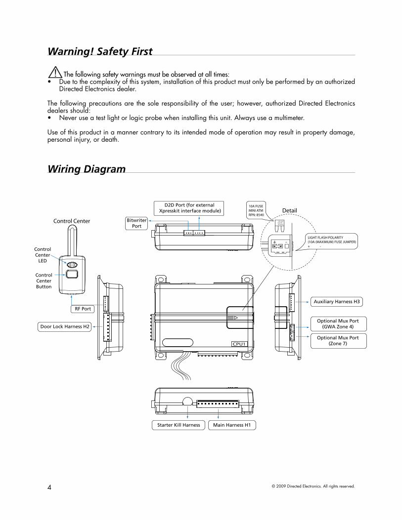
Wiring Diagram
CPU1
+ -LIGHT FLASH POLARITY (10A (MAXIMUM) FUSE JUMPER) + -
BitwriterPort
D2D Port (for external Xpresskit interface module) Detail
Control Center
Optional Mux Port(GWA Zone 4)
Optional Mux Port(Zone 7)
RF Port
Auxiliary Harness H3
ControlCenterButton
ControlCenter
LED
10A FUSEMINI ATM
RPN: 8540
10A FUSE MINI ATM RPN: 8540
1
1
1 8
71
1 3
10
12
Door Lock Harness H2
Main Harness H1Starter Kill Harness

5© 2009 Directed Electronics. All rights reserved.
Wiring ConnectionsMain Harness (H1), 12-pin connector
10A
FU
SEM
INI A
TMRP
N: 8
540
LIG
HT
FLA
SH P
OLA
RITY
(10A
(MAX
IMU
M) F
USE
JUM
PER)
+
-
09
11
10
06
08
0722
66
88
77 11
1 10
11
1 1099
55
1
2
1
244 33
ELECTRONICS
R
31
42
TACH LEARN THREASHOLDJMP1 OFF ON
CPU1
NOTE: Pin 1 is on the leftTACH threshold OFF:
TACH threshold ON:
BitwriterPort
Neutral SafetySwitch
RemoteStart In
Status LED
ValetPort
Door Lock/Unlock Output
Relay OutPort
H2 Port
110 9 8 7 6
12345
1
1 8
51
1 3
10
12
To changejumpersettings
1 12
H1/1 RED/WHITE (-) 200mA AUX/TRUNK OUTPUT
H1/2 RED (+)12VDC CONSTANT INPUT
H1/3 BROWN (+) SIREN OUTPUT
H1/4 WHITE/BROWN PARKING LIGHT ISOLATION WIRE - PIN 87a of onboard relay
H1/5 BLACK (-) CHASSIS GROUND
H1/6 VIOLET (+) DOOR TRIGGER INPUT
H1/7 BLUE (-) TRUNK PIN/ INSTANT TRIGGER INPUT (N/C OR N/O)
H1/8 GREEN (-) DOOR TRIGGER INPUT (N/C* OR N/O)
H1/9 BLACK/WHITE (-) 200mA DOME LIGHT SUPERVISION/FLEX RELAY (Programmable) OUTPUT
H1/10 WHITE/BLUE 200 mA AUX 1 OUTPUT
H1/11 WHITE PARKING LIGHT OUTPUT
H1/12 ORANGE (-) 500mA GROUND WHEN ARMED OUTPUT
*When using the normally closed setting, this wire only covers one door. Use auxiliary outputs 2, 3 or 4 (as necessary) programmed as N/C door switch inputs (wired to each individual door of the vehicle) to cover the other doors. The auxiliary outputs are also programmable as N/O door switch inputs so you can connect multiple doors without the use of diodes.When the auxiliaries are programmed for these types of circuits and connected to the vehicle, the alarm reports a door violation when triggered.
Door Lock Harness (H2), 8-pin connector
CPU1
+ -LIGHT FLASH POLARITY (10A (MAXIMUM) FUSE JUMPER) + -
BitwriterPort
Not Used
D2D Port (for external Xpresskit interface module) Detail
Control Center
Optional Mux Port(GWA Zone 4)
Optional Mux Port(Zone 7)
RF Portfor IVU
10A FUSEMINI ATM
RPN: 8540
10A FUSE MINI ATM RPN: 8540
1
1
1 8
71
1 3
10
12
H2/1 VIOLET* UNLOCK #87 NORMALLY OPEN (INPUT)
H2/2 BLUE/BLACK UNLOCK #30 COMMON (OUTPUT)
H2/3 BROWN/BLACK UNLOCK #87a NORMALLY CLOSED
H2/4 VIOLET/BLACK* LOCK #87 NORMALLY OPEN (INPUT)
H2/5 GREEN/BLACK LOCK #30 COMMON (OUTPUT)
H2/6 WHITE/BLACK LOCK #87a NORMALLY CLOSED
H2/7 WHITE/VIOLET FLEX RELAY #87 NORMALLY OPEN (INPUT)**
H2/8 WHITE/BROWN FLEX RELAY #87a NORMALLY CLOSED**
* Violet and Violet/Black are common at the fuse holder.** These wires work in conjunction with the Black/white H1/9 wire. The white/violet determines what the polarity of the H1/9 wire will be and the white/brown will only be used if a five wire circuit is required.
Auxiliary Harness (H3) 7-pin connector
CPU1
+ -LIGHT FLASH POLARITY (10A (MAXIMUM) FUSE JUMPER) + -
BitwriterPort
Not Used
D2D Port (for external Xpresskit interface module) Detail
Control Center
Optional Mux Port(GWA Zone 4)
Optional Mux Port(Zone 7)
RF Portfor IVU
10A FUSEMINI ATM
RPN: 8540
10A FUSE MINI ATM RPN: 8540
1
1
1 8
71
1 3
10
12
H3/1 ORANGE/BLACK (-) 200mA AUX 4 OUTPUT
H3/2 WHITE/BLACK (-) 200mA AUX 3 OUTPUT
H3/3 VIOLET/BLACK (-) 200mA AUX 2 OUTPUT
H3/4 LIGHT GREEN/BLACK (-) 200mA FACTORY ALARM DISARM OUTPUT
H3/5 YELLOW (+) IGNITION INPUT
H3/6 BROWN (-) 200mA HORN HONK OUTPUT
H3/7 GREY (-) HOOD PIN INPUT (N/C OR N/O)
Starter Kill Harness, 3-pin connector
10A
FU
SEM
INI A
TMRP
N: 8
540
LIG
HT
FLA
SH P
OLA
RITY
(10A
(MAX
IMU
M) F
USE
JUM
PER)
+
-
09
11
10
06
08
0722
66
88
77 11
1 10
11
1 1099
55
1
2
1
244 33
ELECTRONICS
R
31
42
TACH LEARN THREASHOLDJMP1 OFF ON
CPU1
NOTE: Pin 1 is on the leftTACH threshold OFF:
TACH threshold ON:
BitwriterPort
Neutral SafetySwitch
RemoteStart In
Status LED
ValetPort
Door Lock/Unlock Output
Relay OutPort
H2 Port
110 9 8 7 6
12345
1
1 8
51
1 3
10
12
To changejumpersettings
1 12
1 GREEN/WHITE STARTER - COMMON (KEY SIDE)
2 GREEN STARTER - NORMALLY OPEN (MOTOR SIDE)
6 © 2009 Directed Electronics. All rights reserved.
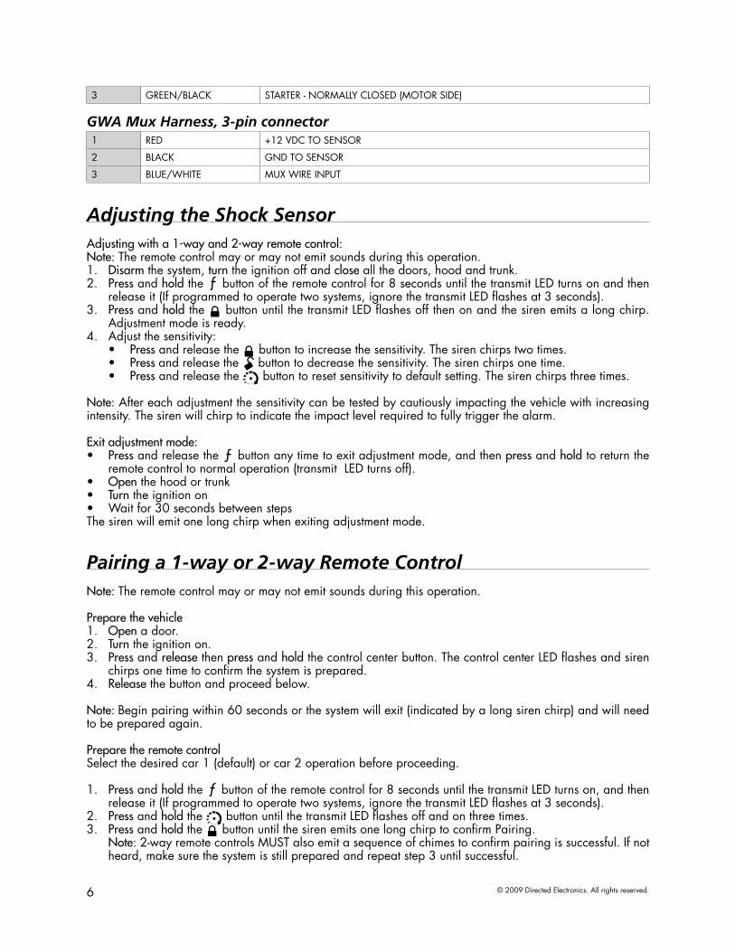
3 GREEN/BLACK STARTER - NORMALLY CLOSED (MOTOR SIDE)
GWA Mux Harness, 3-pin connector1 RED +12 VDC TO SENSOR
2 BLACK GND TO SENSOR
3 BLUE/WHITE MUX WIRE INPUT
Adjusting the Shock SensorAdjusting with a 1-way and 2-way remote control:Note: The remote control may or may not emit sounds during this operation.
Disarm1. the system, turn the ignition off and close all the doors, hood and trunk.Press2. and hold the
AUX
button of the remote control for 8 seconds until the transmit LED turns on and then release it (If programmed to operate two systems, ignore the transmit LED flashes at 3 seconds).Press3. and hold the
AUX
button until the transmit LED flashes off then on and the siren emits a long chirp. Adjustment mode is ready.Adjust the sensitivity:4.
Press• and release the AUX
button to increase the sensitivity. The siren chirps two times.Press • and release the
AUX
button to decrease the sensitivity. The siren chirps one time.Press• and release the AUX button to reset sensitivity to default setting. The siren chirps three times.
Note: After each adjustment the sensitivity can be tested by cautiously impacting the vehicle with increasing intensity. The siren will chirp to indicate the impact level required to fully trigger the alarm.
Exit adjustment mode:Press• and release the
AUX
button any time to exit adjustment mode, and then press and hold to return the remote control to normal operation (transmit LED turns off).Open• the hood or trunkTurn• the ignition onWait for 30 seconds between steps•
The siren will emit one long chirp when exiting adjustment mode.
Pairing a 1-way or 2-way Remote ControlNote: The remote control may or may not emit sounds during this operation.
Prepare the vehicleOpen1. a door. Turn2. the ignition on. Press3. and release then press and hold the control center button. The control center LED flashes and siren chirps one time to confirm the system is prepared.Release4. the button and proceed below.
Note: Begin pairing within 60 seconds or the system will exit (indicated by a long siren chirp) and will need to be prepared again.
Prepare the remote controlSelect the desired car 1 (default) or car 2 operation before proceeding.
Press1. and hold the
AUX
button of the remote control for 8 seconds until the transmit LED turns on, and then release it (If programmed to operate two systems, ignore the transmit LED flashes at 3 seconds).Press2. and hold the AUX button until the transmit LED flashes off and on three times. Press3. and hold the
AUX
button until the siren emits one long chirp to confirm Pairing. Note: 2-way remote controls MUST also emit a sequence of chimes to confirm pairing is successful. If not heard, make sure the system is still prepared and repeat step 3 until successful.

7© 2009 Directed Electronics. All rights reserved.
To exit Pairing mode:Turn off the ignition, the siren will emit one long chirp. 1. Press and hold the 2.
AUX
button on the remote and then press and hold to return the remote control to normal operation (transmit LED turns off).
Programming System FeaturesThe System Features Learn Routine dictates how the unit operates. It is possible to access and change most of the feature settings using the Control button.
Open1. a door. Turn2. the ignition on, then off. Select3. a Menu. Press and hold the Control button. The number of siren chirps indicates the menu num-ber. 1 chirp indicates menu 1, 2 chirps for menu 2.When the desired menu chirps are heard, 4. release the Control button.Select5. a Feature. Press and release the Control button the number of times corresponding to the feature you wish to change. Then press and hold one more time to select the features.Program6. the Feature. While holding the Control button, you can program the feature using the remote control.
For features with only two options; AUX
= option 1 while AUX
= option 2. For features with more than two options;
AUX
selects the options in ascending order, while AUX
selects them in descending order.
Note: Pressing AUX button resets the feature to the factory default.
Once a feature is programmed:Other features can be programmed within the same menu•Another menu can be selected•The learn routine can be exited if programming is complete•
To access another feature in the same menu:Press1. and release the Control button the number of times necessary to advance from the feature you just programmed to the next one you want to program.Then 2. press the Control button once more and hold it.
To select another menu:Press1. and hold the Control button.After 3 seconds, the unit advances to the next menu and the siren chirps, indicating which menu has been 2. accessed.
The learn routine exits if any of the following occurs:The open door is closed•The ignition is turned On•There is no activity for 30 seconds•The Control button is pressed too many times•
8 © 2009 Directed Electronics. All rights reserved.
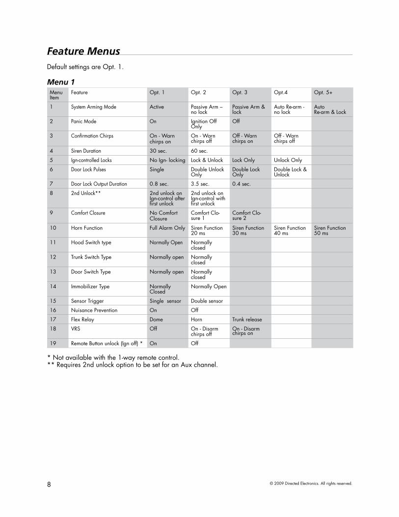
Feature MenusDefault settings are Opt. 1.
Menu 1Menu Item
Feature Opt. 1 Opt. 2 Opt. 3 Opt.4 Opt. 5+
1 System Arming Mode Active Passive Arm – no lock
Passive Arm & lock
Auto Re-arm - no lock
Auto Re-arm & Lock
2 Panic Mode On Ignition Off Only
Off
3 Confirmation Chirps On - Warn chirps on
On - Warn chirps off
Off - Warn chirps on
Off - Warn chirps off
4 Siren Duration 30 sec. 60 sec.
5 Ign-controlled Locks No Ign- locking Lock & Unlock Lock Only Unlock Only
6 Door Lock Pulses Single Double Unlock Only
Double Lock Only
Double Lock & Unlock
7 Door Lock Output Duration 0.8 sec. 3.5 sec. 0.4 sec.
8 2nd Unlock** 2nd unlock on Ign-control after first unlock
2nd unlock on Ign-control with first unlock
9 Comfort Closure No Comfort Closure
Comfort Clo-sure 1
Comfort Clo-sure 2
10 Horn Function Full Alarm Only Siren Function 20 ms
Siren Function 30 ms
Siren Function 40 ms
Siren Function 50 ms
11 Hood Switch type Normally Open Normally closed
12 Trunk Switch Type Normally open Normallyclosed
13 Door Switch Type Normally open Normallyclosed
14 Immobilizer Type Normally Closed
Normally Open
15 Sensor Trigger Single sensor Double sensor
16 Nuisance Prevention On Off
17 Flex Relay Dome Horn Trunk release
18 VRS Off On - Disarm chirps off
On - Disarm chirps on
19 Remote Button unlock (Ign off) * On Off
* Not available with the 1-way remote control.** Requires 2nd unlock option to be set for an Aux channel.

9© 2009 Directed Electronics. All rights reserved.
1. System Arming modeActive: the transmitter must be used to arm the system1. Passive Arm w/o lock: after exiting the vehicle the system will automatically arm. The doors will not 2. lockPassive Arm w/lock: after exiting the vehicle the system will automatically arm and lock the doors3. Auto re-arm w/o lock: if the vehicle is not entered after receiving a disarm command, the system will 4. automatically re-arm. The doors will not lockAuto re-arm w/lock: if the vehicle is not entered after receiving a disarm command, the system will 5. automatically re-arm and lock the doors
2. Panic ModeOn: the Panic output can be activated at any time1. Ign Off Only : the Panic output can be activated only when the ignition is off2. Off: the Panic output is defeated3.
3. Confirmation ChirpsOn w/Warn Chirps On: arm, disarm, and sensor warn-away chirps are active1. On w/Warn Chirps Off: arm and disarm chirps are active, warn-away chirps are defeated2. Off w/Warn Chirps On: arm and disarm chirps are defeated, warn-away chirps are active3. Off w/Warn Chirps Off: arm, disarm, and sensor warn-away chirps are defeated4.
4. Siren Duration30sec: the siren output for full trigger activations and Panic mode is 30 seconds1. 60sec: the siren output for full trigger activations and Panic mode is 60 seconds2.
5. Ign-controlled LocksNo Ign-locking: the door lock/unlock outputs will not activate when ignition is turned on/off1. Lock & Unlock: the door lock & unlock output will activate when ignition is turned on & off2. Lock Only: the door lock output will activate when ignition is turned on3. Unlock Only: the door unlock output will activate when ignition is turned off4.
6. Door Lock PulsesSingle: the door lock & unlock outputs will pulse once1. Double Unlock only: the unlock output only will pulse twice2. Double Lock Only: the lock output only will pulse twice3. Double Lock & Unlock: the lock & unlock outputs will pulse twice4.
7. Door Lock Output Duration0.8sec.: the door lock output pulses will be 800ms in duration1. 3.5sec.: the door lock pulses will be 3.5 seconds in duration2. 0.4 sec.: the door lock pulses will be 400ms in duration3.
8. Ignition Controlled 2nd UnlockAfter first unlock: for Ign-controlled unlocking, the 2nd unlock will activate 800ms after the first (driver 1. door) unlockWith first unlock: for Ign-controlled unlocking, the 2nd unlock will activate at the same time as the first 2. (driver door) unlock
9. Comfort ClosureNo comfort Closure: Comfort Closure is defeated when arming1. Comfort Closure 1: the door lock pulse (or 2nd pulse for double pulses) will remain on for 20 sec-2. onds.Comfort Closure 2: 800mS following the end of the door lock pulse (or 2nd pulse for double pulses); 3. the door lock output will turn on again for 20 seconds.
10. Horn FunctionFull Alarm Only: the horn output will pulse only during full trigger events.1. Siren Function 20/30/40/50ms: The horn output will emulate the siren output with selectable chirp 2. output timing to compensate for OEM horn inefficiency.
10 © 2009 Directed Electronics. All rights reserved.
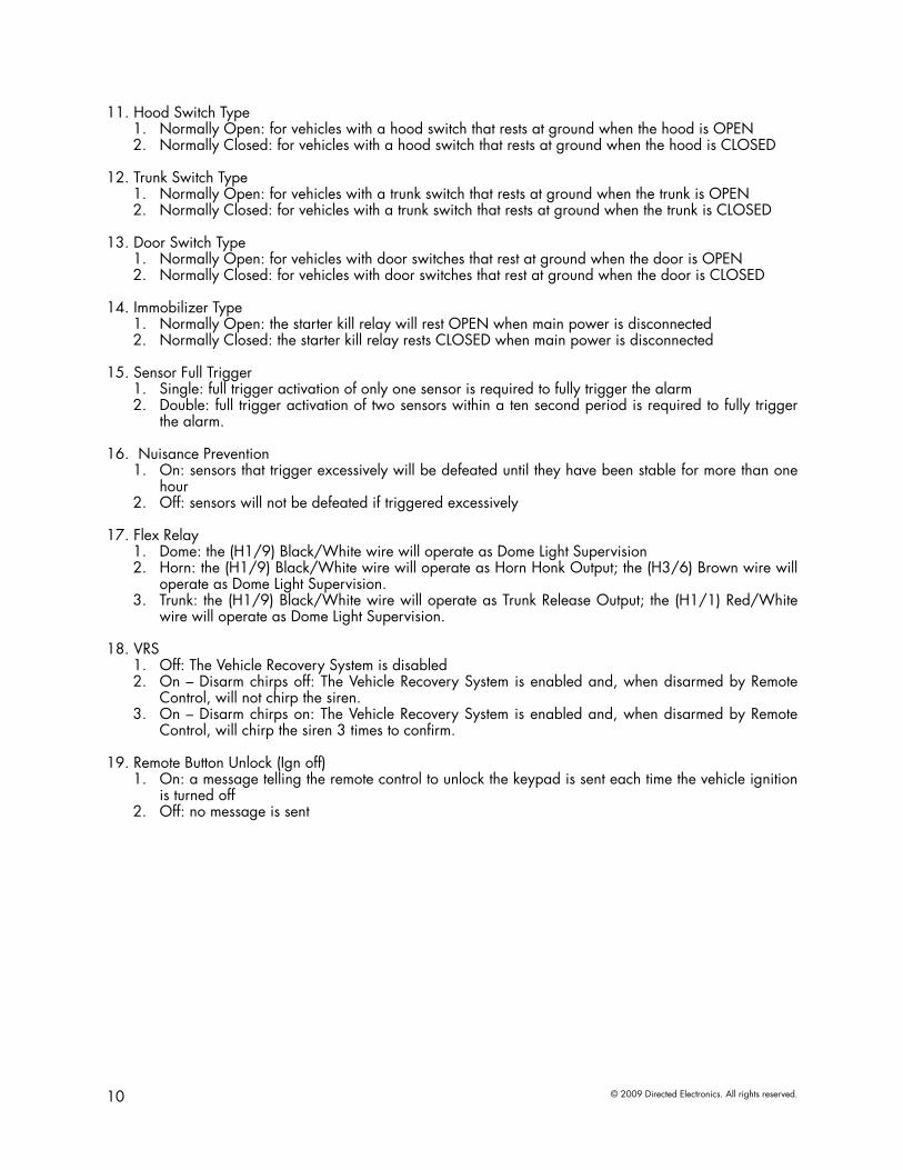
11. Hood Switch TypeNormally Open: for vehicles with a hood switch that rests at ground when the hood is OPEN1. Normally Closed: for vehicles with a hood switch that rests at ground when the hood is CLOSED2.
12. Trunk Switch TypeNormally Open: for vehicles with a trunk switch that rests at ground when the trunk is OPEN1. Normally Closed: for vehicles with a trunk switch that rests at ground when the trunk is CLOSED2.
13. Door Switch TypeNormally Open: for vehicles with door switches that rest at ground when the door is OPEN1. Normally Closed: for vehicles with door switches that rest at ground when the door is CLOSED2.
14. Immobilizer TypeNormally Open: the starter kill relay will rest OPEN when main power is disconnected1. Normally Closed: the starter kill relay rests CLOSED when main power is disconnected2.
15. Sensor Full TriggerSingle: full trigger activation of only one sensor is required to fully trigger the alarm1. Double: full trigger activation of two sensors within a ten second period is required to fully trigger 2. the alarm.
16. Nuisance PreventionOn: sensors that trigger excessively will be defeated until they have been stable for more than one 1. hourOff: sensors will not be defeated if triggered excessively2.
17. Flex RelayDome: the (H1/9) Black/White wire will operate as Dome Light Supervision 1. Horn: the (H1/9) Black/White wire will operate as Horn Honk Output; the (H3/6) Brown wire will 2. operate as Dome Light Supervision. Trunk: the (H1/9) Black/White wire will operate as Trunk Release Output; the (H1/1) Red/White 3. wire will operate as Dome Light Supervision.
18. VRSOff: The Vehicle Recovery System is disabled1. On – Disarm chirps off: The Vehicle Recovery System is enabled and, when disarmed by Remote 2. Control, will not chirp the siren.On – Disarm chirps on: The Vehicle Recovery System is enabled and, when disarmed by Remote 3. Control, will chirp the siren 3 times to confirm.
19. Remote Button Unlock (Ign off)On: a message telling the remote control to unlock the keypad is sent each time the vehicle ignition 1. is turned offOff: no message is sent2.
11© 2009 Directed Electronics. All rights reserved.
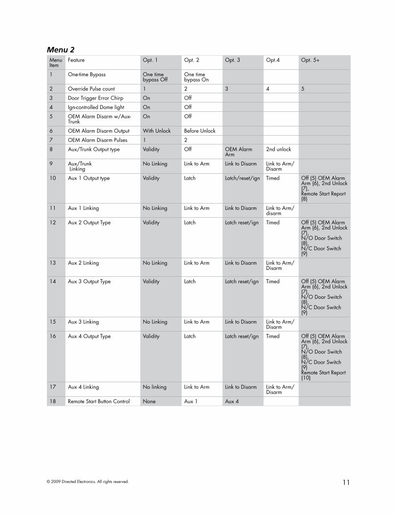
Menu 2Menu Item
Feature Opt. 1 Opt. 2 Opt. 3 Opt.4 Opt. 5+
1 One-time Bypass One time bypass Off
One time bypass On
2 Override Pulse count 1 2 3 4 5
3 Door Trigger Error Chirp On Off
4 Ign-controlled Dome light On Off
5 OEM Alarm Disarm w/Aux-Trunk
On Off
6 OEM Alarm Disarm Output With Unlock Before Unlock
7 OEM Alarm Disarm Pulses 1 2
8 Aux/Trunk Output type Validity Off OEM Alarm Arm
2nd unlock
9 Aux/Trunk Linking
No Linking Link to Arm Link to Disarm Link to Arm/Disarm
10 Aux 1 Output type Validity Latch Latch/reset/ign Timed Off (5) OEM Alarm Arm (6), 2nd Unlock (7), Remote Start Report (8)
11 Aux 1 Linking No Linking Link to Arm Link to Disarm Link to Arm/disarm
12 Aux 2 Output Type Validity Latch Latch reset/ign Timed Off (5) OEM Alarm Arm (6), 2nd Unlock (7), N/O Door Switch (8), N/C Door Switch (9)
13 Aux 2 Linking No Linking Link to Arm Link to Disarm Link to Arm/Disarm
14 Aux 3 Output Type Validity Latch Latch reset/ign Timed Off (5) OEM Alarm Arm (6), 2nd Unlock (7), N/O Door Switch (8), N/C Door Switch (9)
15 Aux 3 Linking No Linking Link to Arm Link to Disarm Link to Arm/Disarm
16 Aux 4 Output Type Validity Latch Latch reset/ign Timed Off (5) OEM Alarm Arm (6), 2nd Unlock (7), N/O Door Switch (8),N/C Door Switch (9) Remote Start Report (10)
17 Aux 4 Linking No linking Link to Arm Link to Disarm Link to Arm/Disarm
18 Remote Start Button Control None Aux 1 Aux 4

12 © 2009 Directed Electronics. All rights reserved.
1. One-time BypassOff: One-Time Bypass is not available1. On: the One-Time Bypass feature will defeat Passive Arming once and, if Armed by remote control, 2. will defeat Comfort Closure and Aux outputs linked to Arming
2. Override Pulse Count1-5: sets the number of presses (1-5) on the Control Button required to override the alarm system•
3. Door Trigger error ChirpOn: if the door trigger is active when arming, the siren will emit a chirp and a message will be sent 1. to the 2way remote control as an alertOff: an active door trigger when arming will not create an alert output2.
4. Ign-controlled Dome lightOn: the dome light output will activate when the ignition is turned off1. Off: the dome light output will not activate when the ignition is turned off2.
5. OEM Alarm Disarm w/Aux/Trunk On: the OEM Alarm Disarm wire will pulse as programmed when the Aux/Trunk output is activated1. Off: the OEM Alarm Disarm wire will not pulse when the Aux/Trunk output is activated2.
6. OEM Alarm Disarm Output With Unlock: the OEM Alarm Disarm wire will pulse as programmed at the same time as the unlock 1. (Blue) wireBefore Unlock: the OEM Alarm Disarm wire will pulse as programmed before the unlock wire2.
7. OEM Alarm Disarm Pulses 1: the OEM Alarm Disarm wire will pulse once per operation1. 2: the OEM Alarm Disarm wire will pulse twice per operation2.
8. Aux/Trunk Output TypeRefer to Aux 1 Output Type descriptions1.
9. Aux/Trunk LinkingRefer to Aux 1 Linking descriptions1.
10. Aux 1 Output Type Validity: when the Aux command is received the wire will turn on and remain on until the command 1. ceasesLatch: when the Aux command is received the wire will turn on and remain on until the command is 2. received againLatch/reset/Ignition: when the Aux command is received the wire will turn on and remain on until the 3. command is received again or the ignition is turned on/off Timed: when the Aux command is received the wire will turn on for the programmed time duration 4. (default 30sec)Off: the output will not activate for a remote control command, use this option when the Aux com-5. mand controls an external device such as a garage door module OEM alarm arm: the output will not activate for a remote control command, it will pulse when the 6. system arms to activate the OEM alarm system.2nd unlock: the wire will operate as 2nd unlock and will not activate for remote control commands7. Remote start report: the output will pulse once to activate an add-on remote start module and the 8. Trunk Pin wire (H1/7) will be monitored for a ground input to confirm remote start activation.
11. Aux 1 LinkingNo Linking: the Aux output will not activate for a remote control command1. Link to Arm: the Aux output will activate for the Arm command2. Link to Disarm: the Aux output will activate for the Disarm command3. Link to Arm/Disarm: the Aux output will activate for the Arm & Disarm commands4.
5.
13© 2009 Directed Electronics. All rights reserved.
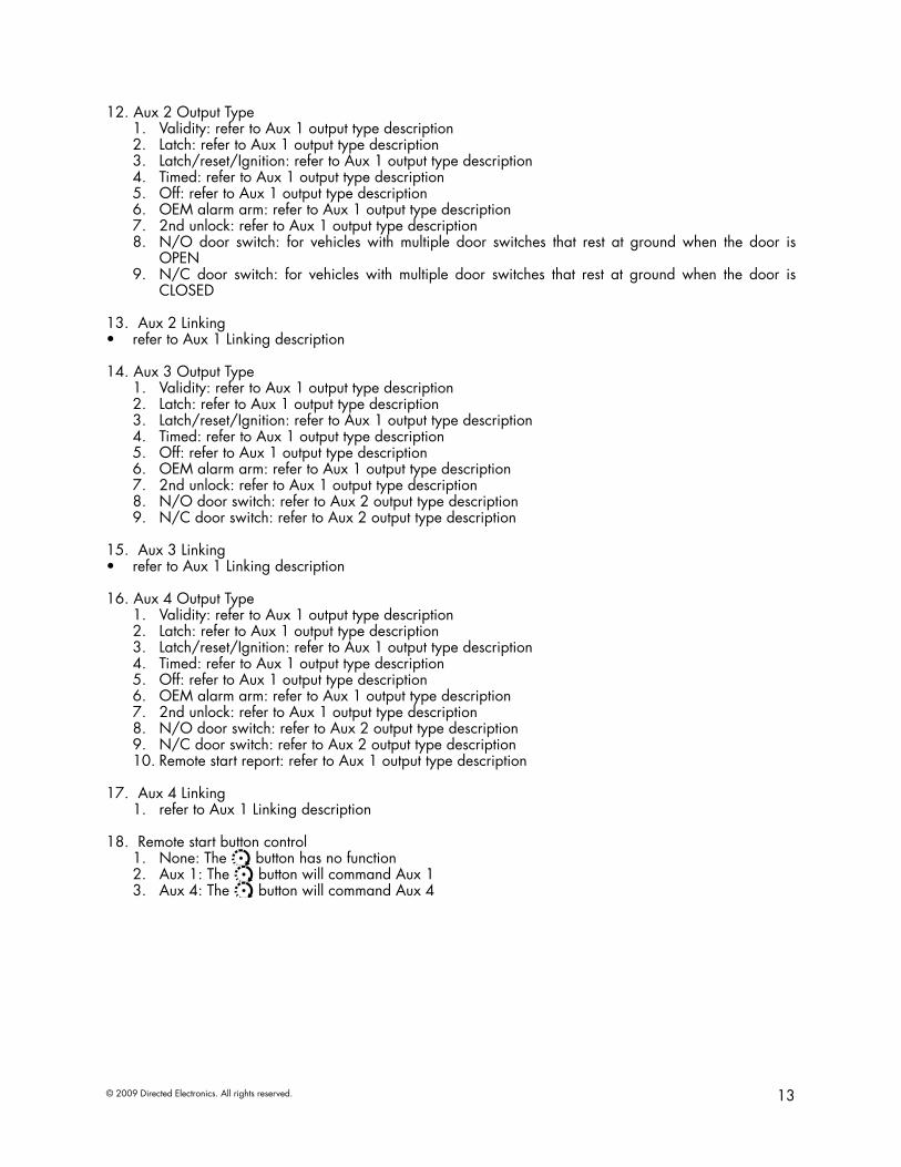
12. Aux 2 Output Type Validity: refer to Aux 1 output type description1. Latch: refer to Aux 1 output type description2. Latch/reset/Ignition: refer to Aux 1 output type description3. Timed: refer to Aux 1 output type description4. Off: refer to Aux 1 output type description5. OEM alarm arm: refer to Aux 1 output type description6. 2nd unlock: refer to Aux 1 output type description7. N/O door switch: for vehicles with multiple door switches that rest at ground when the door is 8. OPENN/C door switch: for vehicles with multiple door switches that rest at ground when the door is 9. CLOSED
13. Aux 2 Linkingrefer to Aux 1 Linking description•
14. Aux 3 Output Type Validity: refer to Aux 1 output type description1. Latch: refer to Aux 1 output type description2. Latch/reset/Ignition: refer to Aux 1 output type description3. Timed: refer to Aux 1 output type description4. Off: refer to Aux 1 output type description5. OEM alarm arm: refer to Aux 1 output type description6. 2nd unlock: refer to Aux 1 output type description7. N/O door switch: refer to Aux 2 output type description8. N/C door switch: refer to Aux 2 output type description9.
15. Aux 3 Linking
refer to Aux 1 Linking description•
16. Aux 4 Output Type Validity: refer to Aux 1 output type description1. Latch: refer to Aux 1 output type description2. Latch/reset/Ignition: refer to Aux 1 output type description3. Timed: refer to Aux 1 output type description4. Off: refer to Aux 1 output type description5. OEM alarm arm: refer to Aux 1 output type description6. 2nd unlock: refer to Aux 1 output type description7. N/O door switch: refer to Aux 2 output type description8. N/C door switch: refer to Aux 2 output type description9. Remote start report: refer to Aux 1 output type description10.
17. Aux 4 Linkingrefer to Aux 1 Linking description1.
18. Remote start button controlNone: The 1. AUX button has no functionAux 1: The 2. AUX button will command Aux 1Aux 4: The 3. AUX button will command Aux 4

14 © 2009 Directed Electronics. All rights reserved.
Bitwriter - Only OptionsIf programming with the Bitwriter®, the learn routine can be locked or unlocked. If the learn routine has previously been locked, it must be unlocked with Bitwriter® - this cannot be done manually with the Control button.
The Bitwriter® gives you access to a wider range of system options. These features and the adjustments that may be programmed are described in the table below.
Menu Item
Feature Default Opt. 2 Opt. 3 Opt.4 Opt. 5+
1 Siren Duration(Seconds)
30 sec. Options: 1 to 180 sec.
2 Shock Sensor Level 7 Options: 0 to 15 in increments of 1
3 Zone 4 Sensor Icon Type* None Shock Field Distur-bance
Tilt Sensor Glass Break/Ultra-sonic/Sensor
4 Zone 7 Sensor Icon Type* None Shock Field Distur-bance
Tilt Sensor Glass Break/Ultra-sonic/Sensor
5 Aux/TrunkIcon type*
Trunk Windows Sunroof Audio Lights/Left dr/ Right dr /Rear Hatch
6 Aux 1Timed Output(Seconds)
30 sec. Options: 1 to 90 sec.
7 Aux 1 Icon type*
Pulsed Trunk Window Sunroof Audio/Lights/Left dr/ Right dr /Rear Hatch/ Timed/ Latched
8 Aux 2Timed Output(Seconds)
30 sec. Options: 1 to 90 sec.
9 Aux 2Icon type*
Pulsed Trunk Window Sunroof Audio/Lights/Left dr/ Right dr /Rear Hatch/ Timed/ Latched
10 Aux 3Timed Output(Seconds)
30 sec. Options: 1 to 90 sec.
11 Aux 3Icon type*
Pulsed Trunk Window Sunroof Audio/Lights/Left dr/ Right dr /Rear Hatch/ Timed/ Latched
12 Aux 4Timed Output(Seconds)
30 sec. Options: 1 to 90 sec.
13 Feature Programming Unlocked Locked
14 Transmitter Programming Unlocked Locked
* Not available with the Responder LE or 1-way remote control.

15© 2009 Directed Electronics. All rights reserved.
Siren Duration: sets the Full Trigger output duration in 1 second intervals up to 180 seconds.1. Sensor 1 level: directly sets the sensor level of the on-board shock sensor2. Zone 4 Sensor Icon Type: sets the Zone 4 (Sensor 2) name to be displayed in the Text Field for Warn-3. away and Full Trigger activationsZone 7 Sensor Icon Type: sets the Zone 7 (Sensor 3) name to be displayed in the Text Field for Warn-4. away and Full Trigger activationsAux/Trunk Icon Type: sets the name to be displayed in the text field when the Aux/Trunk output is acti-5. vated/de-activatedAux 1 Timed Output: sets the output duration in 1 second intervals up to 90 seconds for Aux 16. Aux 1 Icon Type: sets the Accessory name to be displayed in the text field when the Aux 1 output is ac-7. tivated/de-activatedAux 2 Timed Output: sets the Aux 2 “Timed” output in 1 second intervals up to 90 seconds8. Aux 2 Icon Type: sets the Accessory name to be displayed in the text field when the Aux 2 output is ac-9. tivated/de-activatedAux 3 Timed Output: sets the Aux 3 “Timed” output in 1 second intervals up to 90 seconds10. Aux 3 Icon Type: sets the Accessory name to be displayed in the text field when the Aux 3 output is ac-11. tivated/de-activatedAux 4 Timed Output: sets the Aux 4 “Timed” output in 1 second intervals up to 90 seconds12. Feature Programming: locks and unlocks the user’s ability to enter the feature menus and manually 13. change the main unit programming using the Control CenterTransmitter Programming: locks and unlocks the user’s ability to enter the remote control/Reset menu and 14. manually change any functions using the Control Center

16 © 2009 Directed Electronics. All rights reserved.
Basic Remote FunctionsSee Owner’s guide for functionality details on both the LE and 1-way companion remote control.
Reset and DeletionIf a feature needs to be reset or the remote controls need to be deleted, use the following procedure.
Open a door.1. Turn the ignition to the ON position.2. Within 10 seconds, press and release the Control button: 2 times if you want to delete remotes or 3 times 3. to reset features. These function steps are described next.
Delete remotes: This feature erases all remotes from the memory of the security system. This is useful in cases when a customer’s remote is lost or stolen.Note: This does not reset the programmed features of the security system. Reset Features: This resets all features of the security system to the factory default settings. Note: This feature does not delete the remotes from the security system.
Once you have selected the function step, press the Control button once more and hold it. The LED flashes 4. and the siren chirps to confirm the selected functional step. Do not release the Control buttonWhile holding the control button, press the 5.
AUX
button on the remote control. The unit chirps to confirm that the feature has been successfully reset.
Once the feature is reset, the Control button can be released.
Note: For step 1, the + or - Door Trigger Input wire needs to be connected unless using an interface module that supplies the door trigger through D2D.
Long Term Event HistoryThe system stores the last six full triggers in memory. These are not erasable. To access long term event his-tory:
With the ignition Off, 1. press and hold the Control button (on Control Center).Turn2. the ignition On.Release3. the Control button.Within 5 seconds, 4. press and release the Control button. The status LED flashes in groups indicating the last six zones that triggered the unit for 1 minute or until the ignition is turned off (indicated in the order of most recent first to oldest last). Refer to Table of Zones.
Note: The Warn Away triggers are not stored to memory and is not reported.

17© 2009 Directed Electronics. All rights reserved.
Table of ZonesA zone is represented by the number of status LED flashes used by the system to identify a particular type of input.
Zone Description Input Description
1 Trunk Pin H1/7 Blue wire
2 Instant trigger: a heavier impact detected by the onboard shock sensor
On board shock sensor.
3 Door switch trigger H1/8 Green or H1/6 Violet wire
4 Instant trigger: For optional sensors 3 pin optional GWA MUX port
5 Ignition trigger H3/5 Yellow wire
6 Hood Pin H3/7 Grey wire
7 Instant trigger: For optional sensors 4 pin optional MUX port
Troubleshooting: AlarmShock sensor doesn’t trigger the alarm:
Was the onboard shock sensor adjusted before the brain was mounted? If so re-adjust the sensor.1. Has the onboard shock sensor been turned off? The sensor has the ability to be turned off when 2. adjusting.Has the NPC® system been triggered? If so, you hear 5 chirps when disarming. To check this, turn the 3. ignition key on and off to clear the NPC® memory, and then retest the shock sensor. For a detailed description of NPC®, see Nuisance Prevention Circuitry section of the owners guide.
Door input does not immediately trigger full alarm. Instead, chirps are heard for the first 3 seconds:That’s how the progressive two-stage door input works! This is a feature of this system even if the door •is instantly closed again, the progression from chirps to constant siren continues.
Closing the door triggers the system, but opening the door does not:Have you correctly identified the type of door switch system? This happens often when the wrong •door input has been used.
System does not passively arm until it is remotely armed and then disarmed:Is passive arming programmed ON?1. Are the door inputs connected? Is the H1/7 blue wire connected to the door trigger wire in the ve-2. hicle? Either the H1/8 green or the H1/6 violet should be used instead.
Door input does not respond with the progressive trigger, but with immediate full alarm:Does the Status LED indicate that the trigger was caused by the shock sensor? (See • Table of Zones sec-tion of this guide.) The shock sensor, if set to extreme sensitivity, may be detecting the door unlatching before the door switch sends its signal. Reducing the sensitivity can solve this problem.

© 2008 Directed Electronics. All rights reserved.
Assembly Guide: Viper Responder LE Case Below are instructions for disassembly and assembly of the Viper Responder LE, and for thecompanion 1-way remotes. This guide applies to remote controls with Replacement Part Number (RPN) 7251V or 7152V.
1
2
3
12 3 4 5
6
Parts Illustration
Disassembly instructions
Turn the remote control over and remove the bat-1. tery door. Remove the coin cell battery or batteries.2.
Remove Back Housing. The Back Housing is 3. held in place by tabs along its edge. Insert a small slotted screwdriver into gap between Back Housing and Outer Bezel. a. Start in the middle and pry the case up. b. Move the screwdriver along the edge to care fully pry up the tabs at the bottom of the remote. c. Then insert the screwdriver towards the top of the case to pry up the tab. d. Remove Back Housing.
Note: Care must be taken so that the Elastomer contact does not fall out.
Remove the PCB, Printed Circuit Board.4.
Remove Keypad assembly.5.
Assembly instructions (not illustrated) Insert Keypad assembly into Front Housing and 6. Outer Bezel.Insert PCB assembly into Front Housing and 7. Outer BezelInspect Back Housing Assembly to be sure Elas-8. tomer Contact is in place. Assemble the Back Housing to Front Housing 9. and Outer Bezel by snapping tabs in place. Insert coin cell battery or batteries. For 7251V 10. the remote emits beep tones. Install Battery door.11.
Finding the RPN, replacement part numberTurn your remote control over and remove the battery door. With the door removed read the silk-screen on the back case to find the RPN, as shown below.
1-800-274-0200 1-800-274-0200RPN 7251V RPN 7152IC:1513A -7251 IC: 1513A-7152FCC D:EZSDEI7251 FCC ID: EZSDEI7152BATTERY: CR2016 BATTERY: CR2032
Assembly parts: 1. Front housing assembly 2. Outer bezel3. Keypad assembly4. Printed Circuit Board (PCB)5. Back housing assembly6. Elastomer contact7. Battery door
7
3a.
b. c.
d.
4.
5.
ASSY-LE-CASE-VIPER 2008-11
500-10114
Elastomer contact