lionel trainmaster command control upgrade kit owner’s manual · 2004-04-12 · congratulations!...
TRANSCRIPT

72-2960-2501/04
LionelTrainMaster Command
Control Upgrade KitOwner’s Manual

Congratulations!
Congratulations on your purchase of the Lionel TrainMaster Command Control Upgrade Kit!This kit allows you upgrade a Lionel locomotive that has been specifically designated as
“Command upgradeable.” These locomotives were first offered in the 1998 Lionel Catalog.
The Lionel TrainMaster Command Control Upgrade Kit is composed of electroniccircuit boards that are extremely sensitive to static electricity. Please avoid allphysical contact with the chips and handle the boards by their edges only.
To upgrade the Platinum Ghost F-3 (6-38150), the Santa Fe FT (6-18157), the NewYork Central FT (6-18163), or the Baltimore & Ohio FT (6-18169), follow theupgrade instructions in the Owner’s Manual for the particular locomotive.
The Hudson locomotive with the Conventional RailSounds sound system (6-21988)must also have an upgrade to the full RailSounds sound system (Upgrade Kit 6-22963) for proper operation.
2
Note!
Note!
Caution!
The following Lionel marks may be used throughout this instruction manual and are protected under law.All rights reserved.
Lionel®, TrainMaster®, Odyssey®, RailSounds®, CrewTalk™, TowerCom™, DynaChuff™,StationSounds™, Pullmor®, ElectroCoupler™, Magne-Traction®, CAB-1 Remote Controller®,PowerMaster®, Lionel ZW®, ZW®, PowerHouse®, TMCC®, Lionelville™, Lockon®
The name FasTrack® is used with permission from Pitsco, Inc.

Table of contents
Steam locomotive upgrades 4-7
Early Hudson and Pacific locomotive modifications 8-12
Diesel locomotive upgrades 13-14
Reprogramming your locomotive 15
The TrainMaster Command Control environment 16
Running your locomotive in the TrainMaster Command Control environment 17
CAB-1 Remote Controller command for your locomotive 17
Assigning your locomotive a new ID# 18
Notes 19
Limited Warranty/Lionel Service 20
3

Steam locomotive upgrades
Follow these steps to upgrade all steam locomotives, with the exception of the early versionsof the upgradeable Hudson and Pacific locomotives (6-18082, 6-18083, 6-18084, 6-18085,
6-18086, 6-18087, 6-18088, and 6-28000). These exceptions are discussed in the next section.
1. Remove the body screws that secure the locomotive body to the frame and lift away the body.Refer to your locomotive’s manual for the location of these screws.
2. Locate and unplug the 104E circuit board from the motherboard. Refer to Figure 1.
4
Figure 1. Replacing the 104E circuit board
104E circuit board
R2LC circuit board
Make sure that the circuitboard is seated on bothrows of pins.
Note!

Steam locomotive upgrades (continued)
3. Install the R2LC circuit board from the TrainMaster Command Control upgrade kit in theposition made available in Step 2.
4. As illustrated in Figure 2, move the jumper marked JP1 to the next position, leaving theopposite pin open.
5
Figure 2. Changing the jumper location
JP1

Steam locomotive upgrades (continued)
5. Install the locomotive’s body back on the frame, making sure that no wires are pinched.
6. Remove the tender body screws and lift away the body. Refer to the locomotive’s manual forthe locations of the screws.
7. Follow the tether cable to the end of the black insulation and locate the green wire.
8. Determine if the green wire is connected to the four-pin connector. If the wire is connected,reinstall the tender body. The upgrade is complete. Proceed to page 15 to reprogram your locomotive for use in the TrainMaster Command Control environment. If the green wire is notattached, continue with this procedure. Refer Figure 3.
6
Figure 3. Tether cable
Green wire
Tether cable

Steam locomotive upgrades (continued)
9. Pull the black insulating sleeve off the end of the loose green tether wire.
10. Grasp the white housing of the four-pin connector and pull it straight up and off the circuitboard.
11. As illustrated in Figure 4, insert the connector pin at the end of the green wire into theempty fourth position on the connector.
If you are also adding a RailSounds sound system upgrade, install the RailSoundssound system circuit boards as discussed in the RailSounds sound system upgrademanual.
7
12. Replace the body, making sure that the wires are not pinched between the body and theframe.
13. Reprogram the R2LC for your specific locomotive. Refer to page 15.
Note!
Figure 4. Connecting the green wire
Green wire
Metalprojections
Tab
Greenwire
Fourthposition

Early Hudson and Pacific locomotive modifications
Follow these steps to upgrade early versions of the upgradeable Hudson and Pacificlocomotives (6-18082, 6-18083, 6-18084, 6-18085, 6-18086, 6-18087, 6-18088, and
6-28000).
1. Remove the body screws that secure the locomotive to the frame and lift away the body. Referto your locomotive’s manual for the location of these screws.
2. Locate and remove the jumper marked JUMP FOR EUNIT on the motherboard. This positionis to remain open. Refer to Figure 5.
3. As illustrated in Figure 5, move the jumper marked RADIO(FL)/EUNIT to the next position,leaving the opposite pin open.
8
Figure 5. JUMP FOR EUNIT jumper position
Front
Remove jumper atJump for EUNIT
Move jumper atRADIO (FL)/EUNIT
Early Hudson and Pacific locomotive modifications (continued)
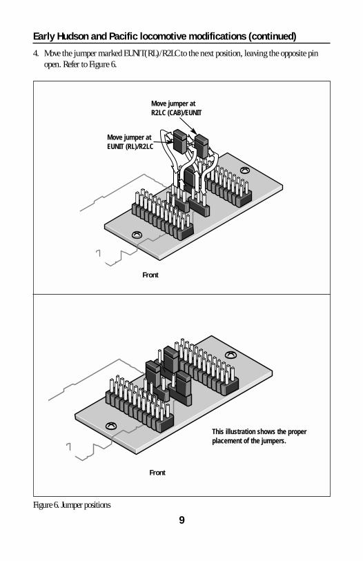
4. Move the jumper marked EUNIT(RL)/R2LC to the next position, leaving the opposite pinopen. Refer to Figure 6.
9Figure 6. Jumper positions
Front
Front
Move jumper atR2LC (CAB)/EUNIT
Move jumper atEUNIT (RL)/R2LC
This illustration shows the properplacement of the jumpers.

Early Hudson and Pacific locomotive modifications (continued)
5. Move the jumper marked R2LC(CAB)/EUNIT to the next position, leaving the opposite pinopen. Refer to Figure 6.
6. As illustrated in Figure 7, install the R2LC circuit board into the slot marked RADIO on themotherboard.
10
Figure 7. R2LC circuit board installation
Front
R2LC circuit board
Rear
Make sure that the circuitboard is seated on bothrows of pins.
Note!

Early Hudson and Pacific locomotive modifications (continued)
7. Install the locomotive’s body back on the frame.
8. Remove the tender body screws and lift away the body.
9. Follow the tether cable to the end of the black insulation and locate the green wire. Thegreen wire should not be connected to any terminal or connector.
10. Pull the black insulating sleeve off the end of the loose green tether wire.
11. Grasp the white housing of the four-pin connector and pull it straight up and off the circuitboard.
12. Insert the connector pin at the end of the green wire into the empty fourth position on theconnector and then plug in the connector. Refer to Figure 8.
11
Figure 8. Connecting the green wire
Install the loosegreen wire
Four-pinLeococonnector
Inside the tender
Five-pin Leococonnector
Metalprojections
Tab
Greenwire
Fourthposition

12
Early Hudson and Pacific locomotive modifications (continued)• If you are not adding a RailSounds sound system upgrade, reinstall the body. The
TrainMaster Command Control upgrade is complete.
• If you are also adding a RailSounds sound system upgrade, install the RailSounds soundsystem circuit boards as discussed in the RailSounds sound system upgrade manual.
13. Replace the body, making sure that the wires are not pinched between the body and theframe.
14. Reprogram the circuit board for use in the TrainMaster Command Control environment.Refer to page 15.

Diesel locomotive upgrades
Follow these steps to upgrade all diesel locomotives.
1. Remove the body screws that secure the locomotive body to the frame and lift away the body.Refer to your locomotive’s manual for the location of these screws.
2. As illustrated in Figure 9, locate and unplug the 104E circuit board from the motherboard.
13
Command Control Board
Front/Cab
104 E Unit
Rear
Figure 9. Replacing the 104E circuit board
Be sure that the circuitboard is seated on bothrows of pins.
Note!
14
Diesel locomotive upgrades (continued)
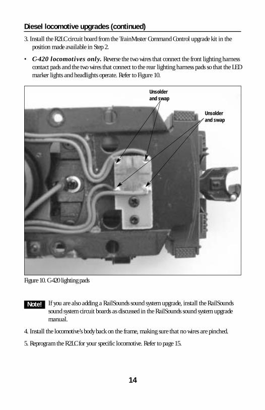
3. Install the R2LC circuit board from the TrainMaster Command Control upgrade kit in theposition made available in Step 2.
• C-420 locomotives only. Reverse the two wires that connect the front lighting harnesscontact pads and the two wires that connect to the rear lighting harness pads so that the LEDmarker lights and headlights operate. Refer to Figure 10.
Note!
Figure 10. C-420 lighting pads
If you are also adding a RailSounds sound system upgrade, install the RailSoundssound system circuit boards as discussed in the RailSounds sound system upgrademanual.
4. Install the locomotive’s body back on the frame, making sure that no wires are pinched.
5. Reprogram the R2LC for your specific locomotive. Refer to page 15.
Unsolderand swap
Unsolderand swap

Reprogramming your locomotive
Before you attempt to operate your locomotive in the TrainMaster Command Controlenvironment, you must reprogram your locomotive’s R2LC circuit board. When you
reprogram the circuit board, you will also assign a unique ENG ID#.
Be sure that no other locomotive is assigned the same ENG ID#.
1. Slide the RUN/PROGRAM switch on your locomotive to the PROGRAM position. Refer toyour locomotive’s instructions for the location of the switch.
2. Plug in the Command Base.
3. Place the locomotive on the track.
4. Turn on track power.
5. On your CAB-1 Remote Controller, press ENG and enter a unique ID# for your locomotive.
Choose any number from 1 to 99.
6. Press the SET button under the front panel of the CAB-1 Remote Controller.
7. Press the AUX1 button, then enter the appropriate reprogramming number for yourlocomotive. See Table 1 below.
8. Turn off track power and wait ten seconds.
9. Remove your locomotive from the track and slide the RUN/PROGRAM switch back to theRUN position.
10. Place the locomotive back on the track, power up, and address your locomotive by pressingENG and entering the unique ID#. You are ready to start TrainMaster Command Controloperations.
Number Locomotive
5 Diesel with Strobe Light (GP-7, GP-9, GP-20)
6 Diesel with Cab Light (FT, F-3)
8 All Diesels with Smoke
34 All Upgradeable Steam Locomotives
Table 1. Reprogramming codes
15
Note!
Note!

16
The TrainMaster Command Control environment
TrainMaster Command Control is the advanced model railroad control system from Lionel.TrainMaster Command Control gives you the power to operate multiple Command-equipped
locomotives on the same track, at the same time. To operate in Command mode, you need a Command Base (6-12911) and a
CAB-1 Remote Controller (6-12868). Find them both at your authorized Lionel retailer.
Place your locomotive on Lionel or Lionel-compatible track.
22Address your locomotive using your CAB-1 RemoteController.
• Press ENG and 1 on the numeric keypad of your CAB-1 RemoteController. This command is sent by your CAB-1 Remote Controller to theCommand Base, which then translates your command into digital code.That code is sent around your railroad’s outside rails in the form of a digital“halo.” All Command-equipped Lionel locomotives listen to this digitalcommunication, but they do not respond until they hear their individual IDnumber—in this case, “1.”
• The digital language of TrainMaster Command Control—andnot track power—controls the actions of Command-equippedLionel engines. Track power is simply like gasoline in the tank of yourcar—it gives you the power to go places, but it doesn’t tell you where to goor how fast to get there.
All Command locomotives come factory-programmed with anID# of “1.” To change the ID# of your locomotive, see page 17.
33Move ‘em out!
• Throttle up or press any command button on the CAB-1Remote Controller. Your locomotive will respond to your everycommand.
11• Make sure track power is OFF before placing on the track.• Make sure your Lionel Command Base is plugged-in and its
communications wire is connected to the COMMON post on your Lioneltransformer or the U terminal on any of your installed PowerMasters or TPC units.
• Once positioned on the track, increase track voltage to FULL (no more than19 volts). On PowerMasters, slide the CMD/CONV switch to CMD. Program TPCunits for Command operation.
Note!
17
Running your locomotive in the TrainMaster Command Controlenvironment
Y our Command-equipped locomotivecomes factory-programmed with an
ID# of “1.” To get your locomotive inaction, set PowerMasters to CMD,program all TPC units for Commandoperation, or set all power supplies onfull (no more than 19 volts). Press ENGand 1 on your CAB-1 Remote Controller.Turn the throttle or press any commandbutton, and your locomotive is ready forCommand operations.
Address Locomotive #1
Set PowerMaster to CMD ortraditional power supplies to fullthrottle (no more than 19 volts)
Press ENG
Press 1 (the ID#)
Throttle up/press any commandbutton
Example
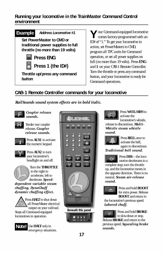
CAB-1 Remote Controller commands for your locomotive
Tender rear couplerreleases. Couplerrelease sounds.
Press AUX2 to turnyour locomotive’sheadlight on and off.
Press WSTL/HRN to activate thelocomotive’s whistle,
release to discontinue. Multi-Whistle steam whistlesound.
Press DIR—the loco-motive decelerates to a
complete stop; turn the throttleup, and the locomotive moves inthe opposite direction. There is noneutral. Steam air-releasesound.
Press BELL once to activate the bell,again to discontinue.
Traditional bell sound.
Press HALT to shut downall PowerMaster electricaloutput on your railroad.
Stops all Command-equippedlocomotives in operation.
Use HALT only inemergency situations.
Turn the THROTTLEto the right toaccelerate, left to
decelerate. Speed-dependent variable steamchuffing. DynaChuffdynamic chuffing effect.
Press and hold BOOSTfor extra power. ReleaseBOOST and return to
the locomotive’s previous speed.Labored chuff.
Press and hold BRAKEto slow down or stop.
Release BRAKE and return to theprevious speed. Squealing brakesounds.
RailSounds sound system effects are in bold italic.
Press AUX1 to activatethe numeric keypad.
Coupler releasesounds.
Note!SET L M H
Beneath this panel

18
Assign a new ID# to yourCommand-equippedlocomotive
Set the Command reverse unit switch toPROGRAM
Command Base plugged inPlace the locomotive on trackPowerMasters set to CMD, program TPC
units for Command operation, ortraditional power supplies ON FULL (nomore than 19 volts)
Turn track power on (PowerMaster’s orTPC unit’s):
Press TR
Enter the PowerMaster’s or TPCunits ID#
Press BOOST
Program the locomotive with a new ID#:
Press ENG
Press a number you choose (the ID#)
Press SET
Set the Command reverse unit switch toRUN
Your locomotive remembers its ID#forever; change it any time with thesesteps
Example
We recommend that you choose an easy toremember ID# for your engine. Some possibilitiesare part of the engine road number, your age, orany two digit number that is not used by anotherengine. Write the number on a small piece of tapeand put this on the bottom of the frame to aid inremembering.
A s your fleet of Command-equippedLionel locomotives grows, you’ll want
to give your locomotive a moreindividualized number. Choose from anybetween 1 and 99. To make things easy, usea portion of your locomotive’s cab number.
Set the locomotive’s Command reverseunit switch to PROGRAM (see Figure 2 on page 5). Plug in the Command Base andplace the locomotive on track, then powerup. Using your CAB-1 Remote Controller,press ENG, the locomotive ID# that youselect, and then press the SET buttonlocated under your CAB-1 RemoteController’s removable panel. Hear thewhistle blow (or see the headlight flash ifthe RailSounds sound system is off); that’sthe Command reverse unit confirming thenew ID#. Set the Command reverse unitswitch to RUN. Your locomotive is ready foroperations with its all-new ID#.
Assigning your locomotive a new ID#

Notes
19

Limited Warranty/Lionel Service
T his Lionel product, including all mechanical and electrical components, moving parts, motors andstructural components, except for light bulbs, is warranted to the original consumer-purchaser, for one
year against original defects in materials or workmanship when purchased through an authorized Lionelmerchant.
This warranty does NOT cover normal wear and tear, light bulbs, defects appearing in the course ofcommercial use, or damage resulting from abuse or misuse of the product by the purchaser. Transfer of thisproduct by the original consumer-purchaser to another person voids this warranty. Modification of this productvoids this warranty.
Any warranted product which is defective in original materials or workmanship and is delivered by theoriginal consumer-purchaser to Lionel L.L.C. or an authorized Lionel L.L.C. Service Center, together with proof oforiginal purchase will, at the option of Lionel L.L.C., be repaired or replaced, without charge for parts or labor. Inthe event the defective product cannot be repaired, and a replacement is not available, a refund of the originalpurchase price will be granted. Any products on which warranty service is sought must be sent freight or postageprepaid, as transportation and shipping charges are not covered by the warranty.
In no event shall Lionel L.L.C. be liable for incidental or consequential damages.Some states do not allow the exclusion or limitation of incidental or consequential damages, so the above
exclusion may not apply to you.This limited warranty gives you specific legal rights, and you may have other rights which vary from state
to state.
Instructions for Obtaining ServiceIf service for this Lionel L.L.C. product is required, bring the item, along with your dated sales receipt and
completed warranty information to the nearest Authorized Lionel Service Center. Your nearest Lionel ServiceCenter can be found by calling 1-800-4-Lionel, or by accessing our Website at www.lionel.com.
If you prefer to send your product back to Lionel L.L.C. for repair in Michigan, you must first call 586-949-4100 or FAX 586-949-5429, or write to Customer Service, P.O. Box 748, New Baltimore, MI 48047-0748,stating what the item is, when it was purchased and what seems to be the problem. You will be sent a returnauthorization letter and label to ensure your merchandise will be properly handled upon receipt.
Once you have received your return authorization and label, make sure that the item is packed to preventdamage during shipping and handling. We suggest that you use the product’s original packaging. Thisshipment must be prepaid and we recommend that it be insured.
Please make sure you have followed all of the above instructions carefully before returning anymerchandise for service. You may choose to have your product repaired by one of our Authorized Lionel ServiceCenters after its warranty has expired. A reasonable service fee will be charged.
Warranty InformationPlease complete the information below and keep it, along with your dated sales receipt. You must present
this and your dated sales receipt when requesting warranty service.
Name ________________________________________________________________________
Address ______________________________________________________________________
Place of Purchase ________________________________________________________________
Date of Purchase ________________________________________________________________
Product Number ________________________________________________________________
Product Description ______________________________________________________________
©2004 LIONEL L.L.C., CHESTERFIELD, MI 48051-2493UNITED STATES OF AMERICAPRINTED IN U.S.A.