owner’s manual - club car...page 2 2007 turf 252/carryall 252/xrt 900 g/e vehicle owner’s manual...
TRANSCRIPT

2007Turf 252/Carryall 252
XRT 900 VehiclesElectric and Gasoline
Owner’s Manual
Turf 252 G/ECarryall 252 G/E
XRT 900 G/E


NOTICE
The Club Car Limited Warranties and the California Emission Control Warranty Statement appear on the lastpages of this manual. No other warranties, express or implied, are contained herein. Your authorized repre-sentative checked the vehicle before it was delivered to you and will provide you a copy of the completed vehi-cle warranty registration form.Club Car is not liable for errors in this manual or for incidental or consequential damages that result from theuse of the material in this manual.This manual contains proprietary information that is protected by copyright. All rights are reserved. No part ofthis manual may be photocopied, reproduced, or translated to another language without the written consentof Club Car, Inc.The information contained in this document is subject to change without notice.Club Car reserves the right to make design changes to vehicles without obligation to make these changes onunits previously sold.These vehicles do not conform to Federal Motor Vehicle Safety Standards for automobiles or to FMVSS 500for low-speed vehicles, and are not equipped for operation on public streets, roads, or highways.
P. O. Box 204658Augusta, Georgia 30917-4658 USA
Telephone 706-863-3000Service Parts Fax 706-855-7413
www.clubcar.com
Copyright © 2006 Club Car, Inc.Club Car, Carryall, PowerDrive, and ArmorFlexare registered trademarks of Club Car, Inc.This manual effective July 31, 2006.
2007 Turf 252/Carryall 252/XRT 900 G/E Vehicle Owner’s Manual Page 1
FOREWORD
Thank you for choosing Club Car, the name most widely recognized as the industry leader in vehicle efficiencyand long-lasting value. You have chosen the finest utility vehicle on the market. Please protect your invest-ment and ensure that your Club Car vehicle(s) provides years of reliable, superior performance by readingand following the maintenance instructions in this manual.Your comfort and safety are important to us, so we urge you to read and follow the step-by-step operatinginstructions and safety procedures in this manual. These instructions must be followed in order to avoid therisk of severe personal injury. If you rent or loan your vehicle to others, we recommend that you ask them toread this manual before they operate the vehicle.Club Car products are backed by a customer support system designed to offer you fast, courteous service. Inthe event that your Club Car vehicle needs repairs or service, we recommend that your local authorized ClubCar representative perform them. For the name and address of the Club Car representative nearest you,logon to our web site at www.clubcar.com or call 1-800-ClubCar (258-2227). If you would prefer to write to us,direct your letter to: Club Car, Attention: Marketing Services, P.O. Box 204658, Augusta, Georgia 30917-4658USA. Your local authorized Club Car representative can also provide technical advice, parts, and servicemanuals.We hope you will consider this owner’s manual a permanent part of your Club Car vehicle. If you sell the vehi-cle, please include the manual so that the next owner will have the important operating, safety, and mainte-nance information it contains.
REGULAR MAINTENANCE ITEMS PERIODIC MAINTENANCE ITEMS
Engine Oil Filter (286 and 351 cc)CCI P/N 1016467
Battery (gasoline vehicle)CCI P/N 1012328
Engine Air Filter (286 cc and 351 cc)CCI P/N 1015426
Spark Plug O.H.V. (286 cc and 351 cc)CCI P/N 101881101
Engine Fuel Filter (286 cc and 351cc)CCI P/N 102003201
Spring Tune-Up KitCCI P/N 101611003
Battery Terminal Protector SprayCCI P/N 1014305
Battery, 6 Volt Trojan T105 (IQ Plus electric vehicle)CCI P/N 101661601 (wet)
Dry Moly LubeCCI P/N 1012151
Battery, 6 Volt Trojan T145 (IQ Plus electric vehicle)CCI P/N 102764401 (wet)
Page 2 2007 Turf 252/Carryall 252/XRT 900 G/E Vehicle Owner’s Manual
TABLE OF CONTENTS
Safety Details ............................................................................................................................................ 11
General Warnings ...................................................................................................................................... 11
General Information ................................................................................................................................... 13
Model Identification .................................................................................................................................... 14
Controls and Indicators .............................................................................................................................. 14
Neutral Lockout Switch .............................................................................................................................. 21
Pre-Operation and Daily Safety Checklist ................................................................................................. 23
Performance Inspection ............................................................................................................................. 23
Driving Instructions .................................................................................................................................... 25
Bed Latch .................................................................................................................................................. 28
Prop Rod ................................................................................................................................................... 28
Loading and Unloading .............................................................................................................................. 29
Towing with the Vehicle ............................................................................................................................. 30
Transporting on a Trailer ........................................................................................................................... 30
Storage – Electric Vehicles ........................................................................................................................ 31
Storage – Gasoline Vehicles ..................................................................................................................... 32
Maintenance .............................................................................................................................................. 34
Periodic Service Schedules ....................................................................................................................... 35
Periodic Lubrication Schedules ............................................................................................................... 38
Vehicle Controller – Electric Vehicles ........................................................................................................ 40
Batteries – Electric Vehicles ...................................................................................................................... 40
Battery Charger – Electric Vehicle ............................................................................................................. 42
Battery – Gasoline Vehicle ........................................................................................................................ 46
Engine Oil – Gasoline Vehicle ................................................................................................................... 47
Fueling Instructions – Gasoline Vehicle .................................................................................................... 50
Cleaning the Vehicle .................................................................................................................................. 51
Accessories ............................................................................................................................................... 51
Subsequent Owner Registration ................................................................................................................ 51
Vehicle Specifications – Gasoline Vehicles ............................................................................................... 52
Vehicle Specifications – Electric Vehicles ................................................................................................. 54
Rear Fender Installation ............................................................................................................................ 56
Wheel and Tire Installation ........................................................................................................................ 58
2007 Turf 252/Carryall 252/XRT 900 G/E Vehicle Owner’s Manual Page 3

Vehicle Feature Identification
GASOLINE TURF 252/CARRYALL 252
Crush area. Can cause severe injury. Stay clear when closing bed.
LATCH
OPEN
WARNING
CCI 101609401
WARNINGYOUNG DRIVERS INCREASE CHANCE OF DEATH
CCI 102075801• Young drivers may not be able to control vehicle. • No drivers younger than 16 years old.
LOW OIL WARNING LAMP
DRIVER/PASSENGERWARNING DECAL
FUEL GAUGE/ HOUR METER
KEY SWITCH
SERIAL NUMBER
CRUSH AREADECAL
OPERATING INSTRUCTIONS DECAL
BED LATCHWARNING DECAL
VEHICLE LOADING DECAL
BRAKEPEDAL
ACCELERATORPEDAL
PARK BRAKEPEDALDIRECTIONAL
ARROW ON TIRE
BED LOADWARNING DECAL
UNDERAGE WARNING DECAL
LAMPSWITCH
Page 4 2007 Turf 252/Carryall 252/XRT 900 G/E Vehicle Owner’s Manual

Vehicle Feature Identification
GASOLINE TURF 252/CARRYALL 252
CHOKE
FUELSHUT-OFF
VALVE
BED LATCH
ROTATING PARTS ANDHOT MANIFOLD DECAL
(ON STARTER/GENERATORAND ENGINE)
GASOLINE WARNING DECAL(AT FUEL FILL)
FRAME GROUND AND GOVERNOR WARNING DECAL(ON FRAME)
TRAILER HITCHDECAL
(ON SEAT SUPPORT PANEL)
WINCH CABLE WARNING DECAL(FOR VEHICLES WITH WINCH ACCESSORY)
(TOP OF PASSENGER SIDE FENDER)ROTATING PARTS DECAL
FORWARD/REVERSEHANDLE (ON DASH)
NEUTRAL LOCKOUT SWITCH DECAL(ON NEUTRAL LOCKOUT BRACKET UNDER SEAT)
2007 Turf 252/Carryall 252/XRT 900 G/E Vehicle Owner’s Manual Page 5

Vehicle Feature Identification
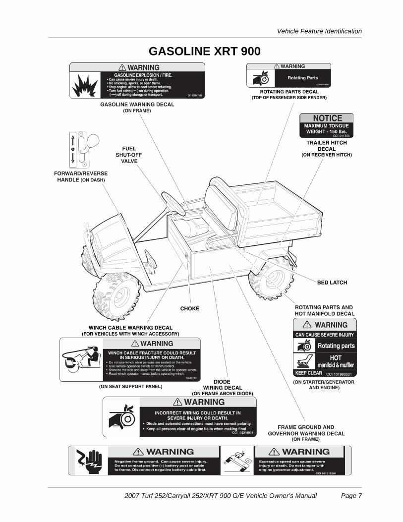
GASOLINE XRT 900
LOW OIL WARNING LAMP
DRIVER/PASSENGERWARNING DECAL
FUEL GAUGE/ HOUR METER
KEY SWITCH
SERIAL NUMBER
CRUSH AREADECAL
OPERATING INSTRUCTIONS
BED LATCHWARNING DECAL
VEHICLE LOADING DECAL
BRAKEPEDAL
ACCELERATORPEDAL
PARK BRAKEPEDALDIRECTIONAL
ARROW ON TIRE
BED LOAD WARNING DECAL
UNDERAGE WARNING DECAL
Page 6 2007 Turf 252/Carryall 252/XRT 900 G/E Vehicle Owner’s Manual
Vehicle Feature Identification
GASOLINE XRT 900
CHOKE
FUEL SHUT-OFF
VALVE
BED LATCH
ROTATING PARTS ANDHOT MANIFOLD DECAL
(ON STARTER/GENERATORAND ENGINE)
GASOLINE WARNING DECAL(ON FRAME)
FRAME GROUND AND GOVERNOR WARNING DECAL
(ON FRAME)
TRAILER HITCHDECAL
(ON RECEIVER HITCH)
(ON SEAT SUPPORT PANEL)
WINCH CABLE WARNING DECAL(FOR VEHICLES WITH WINCH ACCESSORY)
(TOP OF PASSENGER SIDE FENDER)ROTATING PARTS DECAL
DIODE WIRING DECAL
(ON FRAME ABOVE DIODE)
FORWARD/REVERSEHANDLE (ON DASH)
2007 Turf 252/Carryall 252/XRT 900 G/E Vehicle Owner’s Manual Page 7

Vehicle Feature Identification
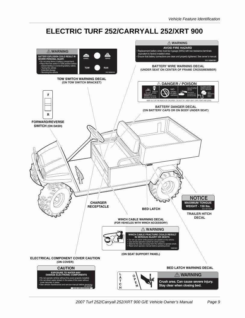
ELECTRIC TURF 252/CARRYALL 252/XRT 900
WARNINGYOUNG DRIVERS INCREASE CHANCE OF DEATH
CCI 102075801• Young drivers may not be able to control vehicle. • No drivers younger than 16 years old.
DRIVER/PASSENGER WARNING DECAL
VEHICLE LOADING DECAL
CRUSH AREADECAL
KEY SWITCH
BED LOAD WARNING DECAL
ACCELERATORPEDAL
BRAKEPEDAL
PARK BRAKEPEDAL
SERIALNUMBER
OPERATING INSTRUCTIONSDECAL
UNDERAGE WARNING DECAL
DIRECTIONALARROWON TIRE
IQDMDIAGNOSTIC
PORT(UNDER DASH)
Page 8 2007 Turf 252/Carryall 252/XRT 900 G/E Vehicle Owner’s Manual
Vehicle Feature Identification
ELECTRIC TURF 252/CARRYALL 252/XRT 900
WINCH CABLE WARNING DECAL(FOR VEHICLES WITH WINCH ACCESSORY)
TRAILER HITCH DECAL
BED LATCH
BATTERY DANGER DECAL(ON BATTERY CAPS OR ON BODY UNDER SEAT)
CHARGERRECEPTACLE
BED LATCH WARNING DECAL
TOW SWITCH WARNING DECAL(ON TOW SWITCH BRACKET)
BATTERY WIRE WARNING DECAL(UNDER SEAT ON CENTER OF FRAME CROSSMEMBER)
FORWARD/REVERSESWITCH (ON DASH)
ELECTRICAL COMPONENT COVER CAUTION(ON COVER)
• Do not operate vehicle without this cover properly installed.• Do not direct water stream in the area of the cover without cover securely in place.• See vehicle maintenance and service manual before servicing.
CCI 102518301
CAUTIONEXPOSURE TO WATER MAY
DAMAGE ELECTRONIC COMPONENTS
(ON SEAT SUPPORT PANEL)
2007 Turf 252/Carryall 252/XRT 900 G/E Vehicle Owner’s Manual Page 9

PROPOSITION 65 - STATE OF CALIFORNIA
This product contains or emits chemicals or substances that have been determined by the state of California to cause cancer and birth defects or other reproductive harm.
! WARNING
Rotating Parts
Practice Safety
Safety signs like you see above may at first seem shocking, but their impact is mild compared with the reality of severe personal injury.Your safety and satisfaction are of the utmost importance to Club Car. That is why before operating the vehicle, we urge you to review the information in this manual. Understand and become familiar with the DANGER, WARNING and CAUTION statements and procedures it contains, along with the safety decals that are affixed to your vehicle. Take time to understand the language of safety. It is a language that can save your life.
Page 10 2007 Turf 252/Carryall 252/XRT 900 G/E Vehicle Owner’s Manual
Safety Details
SAFETY DETAILS
ý WARNING
• This owner’s manual should be read completely before attempting to drive or service thevehicle. Failure to follow the instructions in this manual could result in property damage,severe personal injury, or death.
It is important to note that some vital statements throughout this manual and on the decals affixed to the vehi-cle are preceded by the words DANGER, WARNING, or CAUTION. For your protection, we recommend thatyou take special notice of these safety precautions. Safety precautions are essential and must be followed.
If any of the operation or safety decals on the vehicle become damaged, have been removed, or cannot beeasily read, they should be replaced immediately to avoid possible property damage, personal injury, ordeath. Contact your Club Car distributor/dealer.
ý DANGER
• A DANGER indicates an immediate hazard that will result in severe personal injury or death.
ý WARNING
• A WARNING indicates an immediate hazard that could result in severe personal injury or death.
ý CAUTION
• A CAUTION with the safety alert symbol indicates a hazard or unsafe practice that couldresult in minor personal injury.
CAUTION
• A CAUTION without the safety alert symbol indicates a potentially hazardous situation thatcould result in property damage.
GENERAL WARNINGS
The following safety statements must be heeded whenever the vehicle is being operated, repaired, or ser-viced. Vehicle feature identification is also included beginning on page 4. Other specific safety statementsappear throughout this manual and on the vehicle.
ý DANGER
• Battery – Explosive gases! Do not smoke. Keep sparks and flames away from the vehicle andservice area. Ventilate when charging or operating vehicle in an enclosed area. Wear a fullface shield and rubber gloves when working on or near batteries.
• Gasoline – Flammable! Explosive! Do not smoke. Keep sparks and flames away from thevehicle and service area. Service only in a well-ventilated area.
• Do not operate gasoline vehicle in an enclosed area without proper ventilation. The engineproduces carbon monoxide, which is an odorless, deadly poison.
DANGER CONTINUED ON NEXT PAGE...
2007 Turf 252/Carryall 252/XRT 900 G/E Vehicle Owner’s Manual Page 11
General Warnings
ý DANGER
• A Club Car vehicle will not provide protection from lightning, flying objects, or other storm-related hazards. If caught in a storm while driving a Club Car vehicle, exit the vehicle and seekshelter in accordance with applicable safety guidelines for your location.
ý WARNING
• Follow the procedures exactly as stated in this manual, and heed all DANGER, WARNING, andCAUTION statements in this manual as well as those on the vehicle and battery charger.
• Do not leave children unattended on vehicle.• Prior to leaving the vehicle unattended or servicing the vehicle, set the park brake, place the
Forward/Reverse handle or switch in the NEUTRAL position, turn the key switch to the OFFposition, and remove the key. Chock the wheels when servicing the vehicle.
• Improper use of the vehicle or failure to properly maintain it could result in decreased vehicleperformance, severe personal injury, or death.
• Any modification or change to the vehicle that affects the stability or handling of the vehicle,or increases maximum vehicle speed beyond factory specifications, could result in severepersonal injury or death.
• Check the vehicle for proper location of all vehicle safety and operation decals and make surethey are in place and are easy to read.
• For vehicles with cargo beds, remove all cargo before raising the bed or servicing the vehicle.If the vehicle is equipped with a prop rod, ensure that it is securely engaged while bed israised. Do not close bed until all persons are clear of cargo bed area. Keep hands clear of allcrush areas. Do not drop cargo bed; lower gently and keep entire body clear. Failure to heedthis warning could result in severe personal injury or death.
• Only trained technicians should service or repair the vehicle or battery charger. Anyone doingeven simple repairs or service should have knowledge and experience in electrical andmechanical repair. The appropriate instructions must be used when performing maintenance,service, or accessory installation.
Gasoline vehicles only:• To avoid unintentionally starting the vehicle:
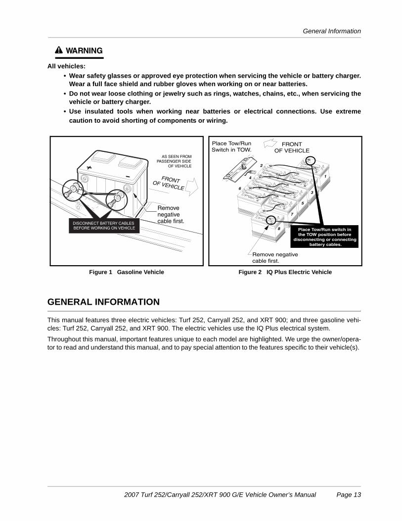
- Disconnect battery cables, negative (–) cable first (Figure 1).- Disconnect the spark plug wire from the spark plug.
• Frame ground – Do not allow tools or other metal objects to contact frame whendisconnecting battery cables or other electrical wiring. Do not allow a positive wire to touchthe vehicle frame, engine, or any other metal component.
Electric vehicles only:• Ensure battery connections are clean and properly tightened. See Battery Care on page 41.• To avoid unintentionally starting the vehicle, disconnect the batteries as shown (Figure 2,
Page 13).• After disconnecting the batteries, wait 90 seconds for the controller capacitors to discharge. • Place Tow/Run switch in the TOW position before disconnecting or connecting the batteries.
Failure to heed this warning could result in a battery explosion or severe personal injury.• Use only 4-gauge (AWG) wires with low-resistance terminals to replace battery wires on IQ
Plus models.WARNING CONTINUED ON NEXT PAGE...
Page 12 2007 Turf 252/Carryall 252/XRT 900 G/E Vehicle Owner’s Manual
General Information
ý WARNING
All vehicles:• Wear safety glasses or approved eye protection when servicing the vehicle or battery charger.
Wear a full face shield and rubber gloves when working on or near batteries.• Do not wear loose clothing or jewelry such as rings, watches, chains, etc., when servicing the
vehicle or battery charger.• Use insulated tools when working near batteries or electrical connections. Use extreme
caution to avoid shorting of components or wiring.
GENERAL INFORMATION
This manual features three electric vehicles: Turf 252, Carryall 252, and XRT 900; and three gasoline vehi-cles: Turf 252, Carryall 252, and XRT 900. The electric vehicles use the IQ Plus electrical system.Throughout this manual, important features unique to each model are highlighted. We urge the owner/opera-tor to read and understand this manual, and to pay special attention to the features specific to their vehicle(s).
Figure 1 Gasoline Vehicle Figure 2 IQ Plus Electric Vehicle
FRONTOF VEHICLE
AS SEEN FROMPASSENGER SIDE
OF VEHICLE
Removenegativecable first.DISCONNECT BATTERY CABLES
BEFORE WORKING ON VEHICLE
1
3
5
7
8
2
4
6
TOW
RUN
WARNING
FRONTOF VEHICLE
Remove negativecable first.
Place Tow/Run switch in the TOW position before
disconnecting or connecting battery cables.
Place Tow/RunSwitch in TOW.
2007 Turf 252/Carryall 252/XRT 900 G/E Vehicle Owner’s Manual Page 13

Model Identification
MODEL IDENTIFICATION
The serial number of the vehicle is printed on a bar code decal (1) mounted on the frame directly above theaccelerator pedal (Example: EG0601-123456) (Figure 3). There is also a second serial number decalmounted on the front body frame behind the center dash panel. The center dash panel must be removed toview this decal. See following NOTE.
NOTE: Have the vehicle serial number available when ordering parts or making inquiries.
CONTROLS AND INDICATORS
See General Warnings on page 11.
ý WARNING
• Before allowing anyone to drive the vehicle, make sure the driver is familiar with all controlsand operating procedures.
• Pedal-start vehicles: Do not shift the Forward/Reverse handle or switch while the vehicle is inmotion. To avoid injury to an unsuspecting passenger or damage to the vehicle, always bringthe vehicle to a full stop before shifting the handle or switch.
• Key-start vehicles: Stop the vehicle before shifting the Forward/Reverse handle. Engine mustbe at idle before shifting the Forward/Reverse handle. Failure to do so may result in injury toinattentive passengers and (or) damage to the vehicle.
• Release the accelerator pedal and then press the brake pedal firmly until the vehicle stops. Toavoid unintentionally starting or rolling the vehicle, set the park brake, place the Forward/Reverse handle or switch in the NEUTRAL position, turn the key switch to the OFF position,and remove the key when leaving the vehicle.
• Gasoline vehicles only: Do not tamper with the governor. Doing so will void the warranty, aswell as damage the engine and other components, and could result in property damage,personal injury, or death due to unsafe speeds.
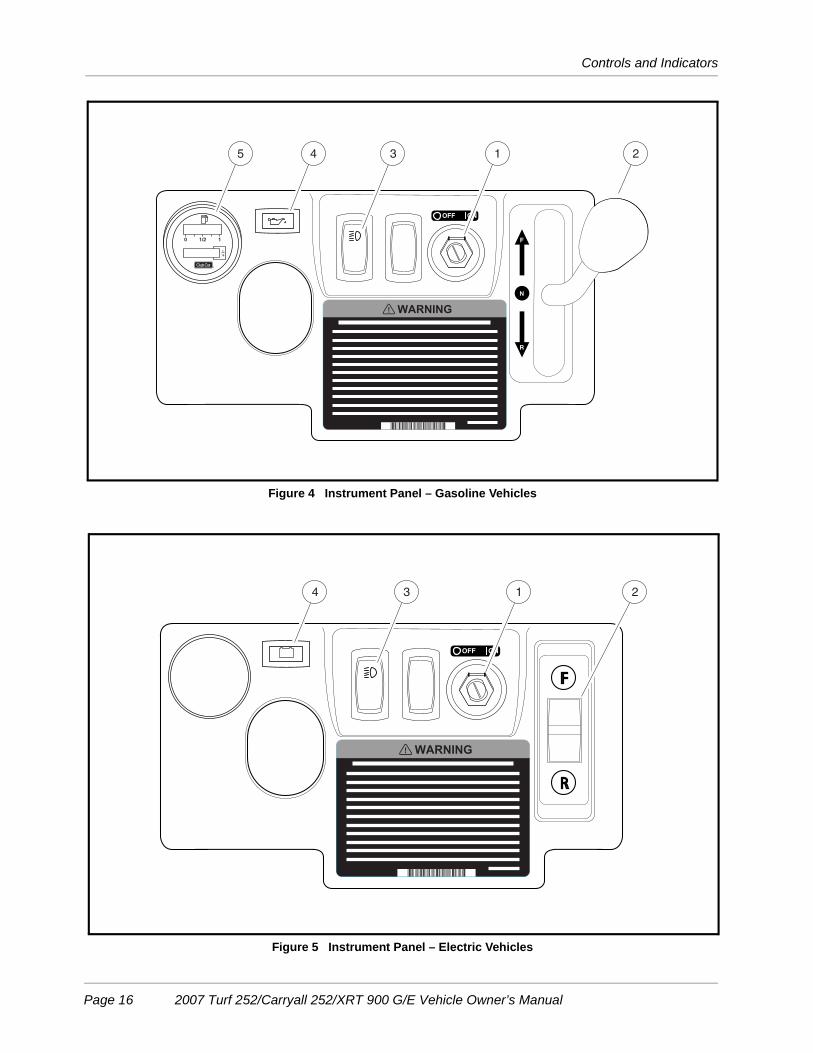
KEY SWITCHThe key switch (1) is mounted on the dash to the right of the steering column (Figure 4 or Figure 5).Each vehicle is equipped with either a two-position key switch or a three-position key switch. Vehiclesequipped with a two-position key switch are referred to as “pedal-start” and vehicles equipped with a three-
Figure 3 Serial Number Decal
This vehicle is covered by one or more of thefollowing U.S. Patents as applicable: D271008D292899, 4343503, 4539162, 4637270, 48218274826467, 5042519, 5083736 and otherpatents pendings.
SERIAL NUMBER
EG0601-123456P O BOX 204658AUGUSTA GA 30917
Club CarR
1
Page 14 2007 Turf 252/Carryall 252/XRT 900 G/E Vehicle Owner’s Manual

Controls and Indicators
position key switch are referred to as “key-start”. All electric vehicles are equipped with a two-position (“pedal-start”) key switch.
• Pedal-start vehicle: The key switch has two positions, OFF and ON, which are clearly labeled.
• Key-start vehicle: The key switch has three positions, OFF, ON and START. To start the vehicle, turnthe key past the ON position to the START position and hold until the engine is running smoothly.Release the key and it will return to the ON position and the engine should idle.
ý WARNING
• Moving parts! Keep clear of the engine compartment while the engine is running.
CAUTION
• Do not “rev” the engine for long periods of time while the Forward/Reverse handle is in theNEUTRAL position. Failure to heed this caution could result in damage to the unitizedtransaxle.
• Do not shift the Forward/Reverse handle while the accelerator pedal is pressed. Shift thehandle only when the vehicle is at a complete stop. Failure to heed this caution could result indamage to the unitized transaxle.
NOTE: The key can be removed only when the key switch is in the OFF position.
FORWARD/REVERSE CONTROL
Gasoline Vehicles
The Forward/Reverse handle (2) is located on the right-hand side of the instrument panel (Figure 4). Thehandle has three distinct positions: F (FORWARD), N (NEUTRAL), and R (REVERSE). Push the handle up tooperate the vehicle in the forward direction, or pull the handle down to operate the vehicle in reverse.
• Pedal-start vehicle: The engine will not run when the handle is in the NEUTRAL position.
• Key-start vehicle: The engine will idle while in the NEUTRAL position. The engine must be at idlebefore shifting the Forward/Revers handle. See WARNING and CAUTION on page 15.
Club Car vehicles operate at reduced speed in reverse. The reverse buzzer will sound as a warning when theForward/Reverse handle is in the REVERSE position.
Electric Vehicles
The Forward/Reverse rocker switch (2) is located on the right-hand side of the instrument panel (Figure 5).The F (FORWARD) and R (REVERSE) positions are clearly marked. Press the FORWARD side of the switchto operate the vehicle in the forward direction, or press the REVERSE side of the switch to operate the vehiclein reverse. When the rocker switch is positioned in NEUTRAL, with neither side down, the vehicle will notoperate if the accelerator pedal is pressed. The reverse buzzer will sound as a warning when the Forward/Reverse switch is in the REVERSE position.
2007 Turf 252/Carryall 252/XRT 900 G/E Vehicle Owner’s Manual Page 15
Controls and Indicators
Figure 4 Instrument Panel – Gasoline Vehicles
Figure 5 Instrument Panel – Electric Vehicles
0 1/2 1
1
10
1345 2
134 2
Page 16 2007 Turf 252/Carryall 252/XRT 900 G/E Vehicle Owner’s Manual

Controls and Indicators
HEADLIGHT CONTROL
Vehicles with HeadlightsThe headlight switch (3) is located on the instrument panel to the right of the steering column (Figure 4 orFigure 5). Press the side of the switch with the headlight symbol to turn the headlights on and press the otherside to turn the headlights off.
NOTE: Gasoline vehicles: Using the headlights for extended periods of time without the engine running,or with the engine idling will discharge the battery.
LOW OIL WARNING LIGHT
Gasoline Vehicles OnlyThe gasoline vehicle is equipped with a low oil warning light (4), located on the instrument panel just abovethe steering column (Figure 4). If the warning light comes on, oil should be checked and added to the engineas necessary before continuing to use the vehicle. The vehicle should never be driven when the low oil warn-ing light remains on. If the warning light goes on and off, the vehicle may be driven, but oil should be addedat the first opportunity. If the oil level is correct and the warning light stays on, have a trained technician checkthe vehicle.
CAUTION
• Failure to add oil immediately when the low oil warning light stays on may result in permanentengine damage.
FUEL GAUGE/HOUR METER
Gasoline Vehicles OnlyThe gasoline vehicle is equipped with a fuel gauge/hour meter (5), located on the instrument panel (Figure 4).The fuel gauge allows the operator to monitor the fuel level in the vehicle. The hour meter should be used bythe trained technician to track vehicle usage and determine when periodic service procedures are required.See Periodic Service Schedule on page 37.
BATTERY WARNING LIGHT
Electric Vehicles OnlyElectric vehicles feature a dash mounted warning light (4) (above steering column) that, when the vehicle isin operation, indicates low battery voltage or, when the vehicle is being charged, indicates a charging problem(Figure 5). The battery warning light is controlled by the onboard computer.
When the vehicle is in operation, the warning light will illuminate and remain illuminated if:
• Batteries’ voltage drops below 48 when there is no load on the batteries (the vehicle is stopped andthere are no accessories on).
• Batteries have discharged to less than 25% of rated capacity.
If the warning light illuminates when the vehicle is operating, there will be enough power remaining to drive thevehicle for approximately 30 minutes. However, the vehicle should be charged at the first opportunity. If thewarning light illuminates and the vehicle is unable to operate for 30 minutes, have your Club Car distributor/dealer check the vehicle for a possible battery or electrical system problem.
2007 Turf 252/Carryall 252/XRT 900 G/E Vehicle Owner’s Manual Page 17

Controls and Indicators
When the batteries receive an incomplete charge because 1) the DC power cord is disconnected, 2) ACpower to the charger is interrupted, 3) automatic charger shut-off occurs after 16 hours of operation, 4) thecharger malfunctions, or 5) the wrong charger is used, the warning light will indicate as follows:
• The warning light will not come on if the charge is 90% or more complete. The onboard computer willretain in memory the amount of charge needed to fully replenish the batteries and will complete thecharge during the next charge cycle.
• When the charger is unplugged, the warning light will illuminate and remain illuminated for 10 secondsif the charge is less than 90% complete but the vehicle has enough power for approximately 30 min-utes of operation. This will alert the operator that the vehicle may be used, but that it must be chargedto completion as soon as possible.
• The warning light will repeatedly illuminate for 10 seconds, with 4 second intervals if the charger timesout at 16 hours and the batteries are not sufficiently charged. See battery charger owner’s manual.This indicates an abnormal charge cycle. The charger and batteries should be checked by your ClubCar distributor/dealer.
• The warning light will repeatedly illuminate for 10 seconds, with 4 second intervals during a chargecycle (DC plug is still connected) if AC power to the charger is interrupted. The light will go out whenAC power is restored.
LED light: In addition to the warning light, there is an infrared LED in the dash light assembly, which transmitsan infrared signal from the onboard computer (OBC). This signal is received by the optional CommunicationDisplay Module, which provides information on the condition of the vehicle and batteries.
BATTERY CONDITION INDICATOR
Electric Vehicles OnlyThe battery condition indicator features a 10-bar LED display that, when the vehicle is in operation, displaysthe level of battery capacity, measuring battery voltage over a period of time.
When batteries are fully charged, all indicator lights will be on. When battery voltage drops below 75% of fulldischarge, the last two indicator lights will flash alternately. Continued use of vehicle after indicator lightsbegin flashing without recharging could result in decreased vehicle performance. See following NOTE.
NOTE: If battery condition indicator moves rapidly (approximately 45 minutes) from full charge display toempty, there may be a problem with the wiring or with a battery cell. If indicator display does notreset back to full after recharging, there may be a problem with the battery charger or with one of thebatteries. In either case the vehicle should be checked by a Club Car dealer or a trained technician.
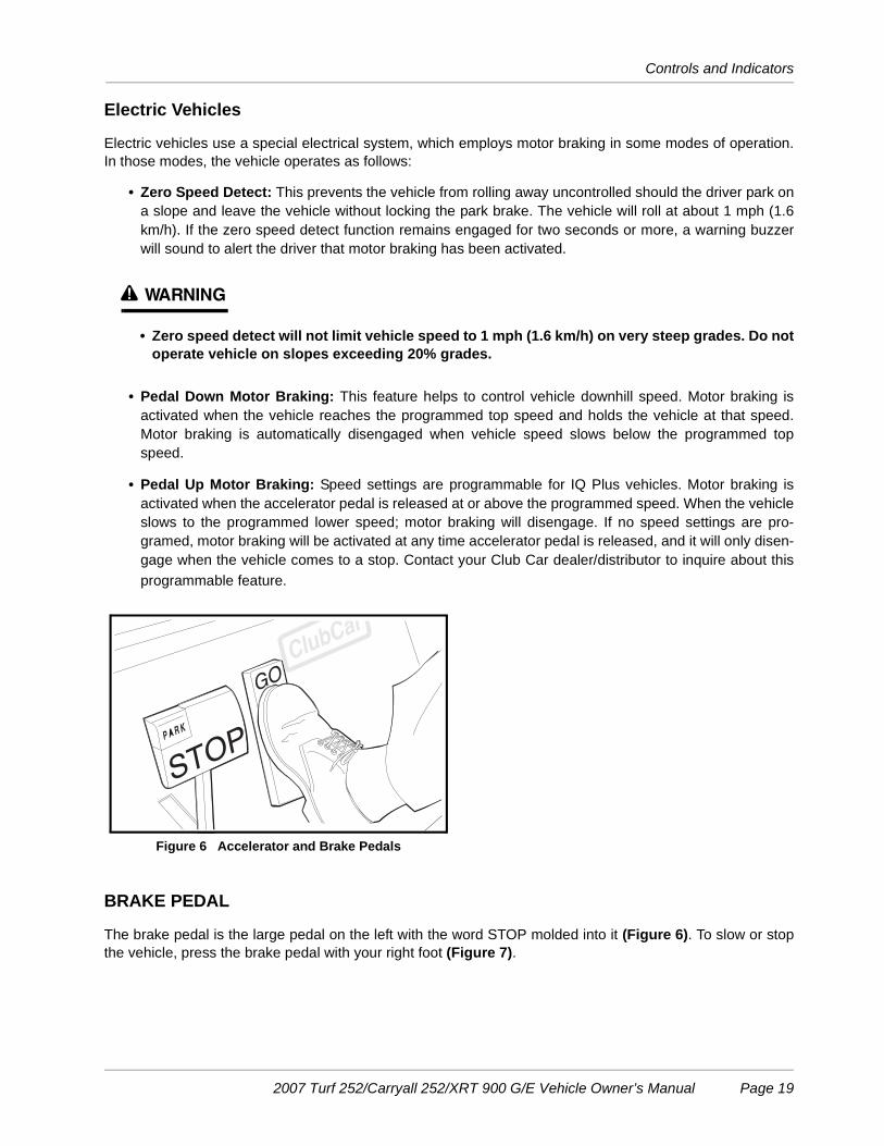
ACCELERATOR PEDALThe accelerator pedal is the pedal on the right, with the word GO molded into it (Figure 6). The operation ofthe accelerator pedal differs from that of an automobile:
• Pedal-start vehicle: When the key switch is in the ON position, and the Forward/Reverse handle orswitch is in either the FORWARD or REVERSE position, pressing the accelerator pedal will automati-cally release the park brake and start the vehicle moving in the direction selected (forward or reverse).When the accelerator is released, power will be cut off and the motor or engine will stop running.
• Key-start vehicle: The engine must first be running before shifting the Forward/Reverse handle andpressing the accelerator pedal. As the accelerator pedal is pressed, speed will increase until full speedis reached. When the accelerator is released, the engine will idle. See WARNING and CAUTION onpage 15.
Page 18 2007 Turf 252/Carryall 252/XRT 900 G/E Vehicle Owner’s Manual
Controls and Indicators
Electric Vehicles
Electric vehicles use a special electrical system, which employs motor braking in some modes of operation.In those modes, the vehicle operates as follows:
• Zero Speed Detect: This prevents the vehicle from rolling away uncontrolled should the driver park ona slope and leave the vehicle without locking the park brake. The vehicle will roll at about 1 mph (1.6km/h). If the zero speed detect function remains engaged for two seconds or more, a warning buzzerwill sound to alert the driver that motor braking has been activated.
ý WARNING
• Zero speed detect will not limit vehicle speed to 1 mph (1.6 km/h) on very steep grades. Do notoperate vehicle on slopes exceeding 20% grades.
• Pedal Down Motor Braking: This feature helps to control vehicle downhill speed. Motor braking isactivated when the vehicle reaches the programmed top speed and holds the vehicle at that speed.Motor braking is automatically disengaged when vehicle speed slows below the programmed topspeed.
• Pedal Up Motor Braking: Speed settings are programmable for IQ Plus vehicles. Motor braking isactivated when the accelerator pedal is released at or above the programmed speed. When the vehicleslows to the programmed lower speed; motor braking will disengage. If no speed settings are pro-gramed, motor braking will be activated at any time accelerator pedal is released, and it will only disen-gage when the vehicle comes to a stop. Contact your Club Car dealer/distributor to inquire about thisprogrammable feature.
BRAKE PEDAL
The brake pedal is the large pedal on the left with the word STOP molded into it (Figure 6). To slow or stopthe vehicle, press the brake pedal with your right foot (Figure 7).
Figure 6 Accelerator and Brake Pedals
2007 Turf 252/Carryall 252/XRT 900 G/E Vehicle Owner’s Manual Page 19

Controls and Indicators
PARK BRAKE PEDAL
The park brake pedal is the small raised portion in the upper left corner of the brake pedal. It has the wordPARK molded into it and the words PARK BRAKE marked on top of it (Figure 6). To set the park brake, pressthe brake pedal firmly and tilt the park brake portion of the pedal forward with your foot (Figure 8). See fol-lowing WARNING.
ý WARNING
• The park brake will release automatically when either the accelerator or brake pedal ispressed. The park brake has multiple locking positions and should be firmly pressed andlocked to prevent the vehicle from rolling.
TOW/RUN SWITCH
Electric Vehicles Only
ý WARNING
• Place Tow/Run switch in the TOW position before disconnecting or connecting the batteries.Failure to heed this warning could result in a battery explosion or severe personal injury.
• When the Tow/Run switch is in the TOW position, all motor braking functions, including zero-speed detect, are disabled.
Electric vehicles are equipped with a Tow/Run switch (1), located on the seat support panel under the seat(Figure 9). The switch must be in the RUN position in order to operate the vehicle. When the switch is in theTOW position, power to the vehicle electrical components is turned off and the vehicle will not operate. Seefollowing NOTE.
NOTE: After placing the Tow/Run switch in the TOW position, allow 10 seconds to elapse before switchingback to the RUN position.
After placing the Tow/Run switch in RUN position, allow 10 seconds to elapse before operating thevehicle.
Figure 7 Brake Pedal Figure 8 Park Brake
Page 20 2007 Turf 252/Carryall 252/XRT 900 G/E Vehicle Owner’s Manual

Neutral Lockout Switch
The Tow/Run switch should be placed in the TOW position under the following conditions:
• Before Towing the Vehicle: Place the Tow/Run switch in the TOW position to disable all motor brakingfunctions, thus preventing possible damage that could occur to the vehicle or electrical components ifthe vehicle is towed while the Zero-Speed Detect motor braking function is operating.
• Before Disconnecting or Connecting Battery Cables: Place the Tow/Run switch in the TOW posi-tion to turn off power to the vehicle electrical system, thus preventing severe arcing and possible bat-tery explosion as the battery cables are disconnected.
• For Long Term Storage: Place the Tow/Run switch in the TOW position to turn off power to the vehicleelectrical system, thus preventing vehicle electrical components from discharging the batteries.
CIRCUIT BREAKER
IQ Plus Electric Vehicles Only
IQ Plus vehicles are equipped with a circuit breaker (2), located next to the Tow/Run switch (Figure 9). If thecircuit breaker has been tripped, a series of rapid beeps will sound and vehicle speed will slow to aproximatelyone-half of its top programmed speed. In the event of a tripped circuit breaker, bring the vehicle to a completestop, remove seat, and push the breaker to reset. If the circuit breaker trips again when vehicle operation isresumed, contact a local Club Car distributor/dealer.
NEUTRAL LOCKOUT SWITCH
Gasoline Pedal-start Vehicles Only
For the convenience of the trained technician, there is a neutral lockout switch located on the seat supportpanel under the seat (Figure 10). The neutral lockout switch has two positions, MAINTENANCE and OPER-ATE, which are clearly marked.
• When the switch is in the MAINTENANCE position, it will allow the technician to run the engine in theNEUTRAL position to perform certain maintenance and/or repair functions. With the switch in this posi-tion, the vehicle will not operate if the Forward/Reverse handle is placed in either the FORWARD orREVERSE position.
Figure 9 Tow/Run Switch – IQ Plus
1
2
2007 Turf 252/Carryall 252/XRT 900 G/E Vehicle Owner’s Manual Page 21

Neutral Lockout Switch
ý WARNING
• With the switch in the MAINTENANCE position and the engine running, the vehicle may movesuddenly if the Forward/Reverse handle is shifted or accidentally bumped. To prevent this,chock the front and rear wheels and firmly set the park brake before servicing or leaving thevehicle.
NOTE: Be sure to return the switch to the OPERATE position after servicing the vehicle, or it will not runwith the Forward/Reverse handle in either the FORWARD or REVERSE position.
CHOKEGasoline Vehicles OnlyThe choke is located on the seat support panel below and to the left of the driver’s left knee. If the vehicle ishard to start in cool or cold temperatures, activate the choke:
• Pull out the choke cable. Hold choke cable out during start-up and release it after the engine starts andruns smoothly (Figure 11).
Figure 10 Neutral Lockout Switch
Figure 11 Cable Choke
Page 22 2007 Turf 252/Carryall 252/XRT 900 G/E Vehicle Owner’s Manual

Pre-Operation and Daily Safety Checklist
PRE-OPERATION AND DAILY SAFETY CHECKLIST
Each Club Car vehicle has been thoroughly inspected and adjusted at the factory; however, upon receivingyour new vehicle(s), you should become familiar with its controls, indicators, and operation. Carefully inspecteach vehicle to ensure that it is in proper working condition before accepting delivery.
Use the following checklist as a guide to inspect the vehicle. This checklist should be used daily to ensure thatthe vehicle is in proper working condition and in conjunction with the Periodic Service Schedules on page 35.Any problems should be corrected by a Club Car distributor/dealer or a trained technician.
• General: All the parts should be in place and properly installed. Be sure that all nuts, bolts, and screwsare tight. On gasoline vehicles, check all hose clamps for tight fit as well as the starter belt for tightness.
• Safety and information decals: Check to ensure that all safety and information decals are in place.See pages 4 through 9.
• Tires: Check for proper tire pressure. Visually inspect for wear, damage, and proper inflation on a dailybasis. See Vehicle Specifications – Gasoline Vehicles on page 52 or Vehicle Specifications –Gasoline Vehicles on page 52.
• Battery(ies): Check electrolyte to ensure that it is at its proper level (Figure 19, Page 41 or Figure 24,Page 46). Check battery posts. Wires should be tight and free of corrosion. On electric vehicles,charge batteries fully before first use of vehicle.
• Charger cord, plug, and receptacle (electric vehicles): Visually inspect for cracks, loose connec-tions, and frayed wiring. See Plug and Receptacle on page 45.
• Engine (gasoline vehicles): Check for proper engine oil level. See Engine Oil – Gasoline Vehicleon page 47.
• Fuel (gasoline vehicles): Check fuel level. See Fueling Instructions – Gasoline Vehicle onpage 50. Check fuel tank, lines, cap, pump, fuel filters, and carburetor for fuel leakage on a daily basis.
• Exhaust system (gasoline vehicles): Check for leaks.
ý WARNING
• Be sure the plastic has been removed from the seat bottom before operating the vehicle.Failure to do so may result in a fire, property damage, personal injury, or death.
PERFORMANCE INSPECTION
After you have familiarized yourself with the vehicle controls and have read and understood the drivinginstructions, take the vehicle for a test drive.
Use the following checklist as a guide to inspect the vehicle and check daily for proper operation. Any prob-lems should be corrected by a Club Car distributor/dealer or a trained technician.
All Vehicles• Forward/Reverse control: Check for proper operation. See Controls and Indicators on page 14.
• Brakes: Be sure the brakes function properly. When brake pedal is fully pressed under moderate pres-sure, it should not go more than halfway to the floor, and vehicle should come to a smooth, straightstop. If the brake pedal goes more than halfway to the floor, or if the vehicle swerves or fails to stop,have the brake system checked and adjusted as required. Brake adjustment must be maintained sothat the brake pedal cannot be pressed to the floor under any circumstance.
2007 Turf 252/Carryall 252/XRT 900 G/E Vehicle Owner’s Manual Page 23

Performance Inspection
• Park brake: When latched, the park brake should lock the wheels and hold the vehicle stationary (onan incline of 20% or less). It should release when either the accelerator or brake pedal is pressed.
• Reverse buzzer: The reverse buzzer should sound as a warning when the Forward/Reverse handle orswitch is in the REVERSE position.
• Steering: The vehicle should be easy to steer and should not have any play in the steering wheel.
• General: Listen for any unusual noises such as squeaks or rattles. Check the vehicle ride and perfor-mance. Have a Club Car distributor/dealer or a trained technician investigate anything unusual.
Electric Vehicles• Accelerator: With the key switch in the ON position and the Forward/Reverse switch in the FOR-
WARD position, as the accelerator pedal is pressed, the motor should start and the vehicle shouldaccelerate smoothly to full speed. Club Car vehicles operate at reduced speed in reverse. When thepedal is released, it should return to the original position and the motor should rotate freely or go intomotor braking mode. See Pedal Up Motor Braking below.
• Zero Speed Detect: With the vehicle parked on level ground and the park brake disengaged, place theTow/Run switch in the RUN position and attempt to push the vehicle. Motor braking should engage andcause resistance to rolling (moving at no more than 1 to 3 mph) (1.5 to 4.8 km/h) with the Forward/Reverse switch in any position. When zero speed detect motor braking is engaged, the reverse buzzershould emit a distinct pattern of beeps. See following WARNING.
ý WARNING
• Zero-speed detect will not limit vehicle speed to 1 mph (1.6 km/h) on very steep grades. Donot operate vehicle on slopes exceeding 20% grades.
• Pedal Up Motor Braking: Accelerate the vehicle to full speed and then release the accelerator pedal.Motor braking should quickly and smoothly slow the vehicle. Motor braking will disengage when vehicleslows to the programmed speed for IQ Plus vehicles. This feature is programmable for IQ Plus vehi-cles. Contact your local Club Car dealer/distributor to inquire about this adjustable feature.
• Pedal Down Motor Braking: Accelerate down an incline with the accelerator pedal pressed. When thevehicle reaches maximum designed speed, motor braking should engage and limit the vehicle to itsmaximum designed speed. On very steep grades, the vehicle may slightly exceed its maximumdesigned speed, requiring use of the brake pedal.
Gasoline Vehicles• Accelerator for pedal-start vehicle: With the key switch in the ON position and the Forward/Reverse
handle in the FORWARD position, as the accelerator pedal is pressed, the engine should start and thevehicle should accelerate smoothly to full speed. When the pedal is released it should return to theoriginal position and the engine should stop. Club Car vehicles operate at reduced speed in reverse.
• Accelerator for key-start vehicle: After starting the engine with the key switch and placing the For-ward/Reverse handle in the FORWARD position, the vehicle should accelerate smoothly to full speedas the accelerator pedal is pressed. When the accelerator pedal is released it should return to the orig-inal position and the engine should idle.
• Governor: Check maximum speed of the vehicle. The gasoline Turf 252 and Carryall 252 should oper-ate at 15-17 mph (24-27 km/h) on a level surface. The gasoline XRT 900 should operate at 17-19 mph(27-31 km/h) on a level surface.
Turf 252 and Carryall 252 electric vehicles should operate at a standard speed of 15-17 mph (24-27km/h) on a level surface. They can be adjusted to a maximum speed of 17-19 mph (27-31 km/h) on a
Page 24 2007 Turf 252/Carryall 252/XRT 900 G/E Vehicle Owner’s Manual
Driving Instructions
level surface. XRT 900 electric vehicles can be set at the factory to operate at either 15-17 mph (24-27km/h) or to 17-19 mph (27-31 km/h) on a level surface.
DRIVING INSTRUCTIONS
ý WARNING
• Only licensed drivers should be allowed to drive the vehicle.• Before allowing anyone to drive the vehicle, make sure the driver is familiar with all controls
and operating procedures.• No one under the age of 16 years should be allowed to drive the vehicle.• No more than two people should be on the vehicle at one time.• Do not allow riders in the cargo bed.• The vehicle is not specially equipped for handicapped persons:
- Be sure all persons can properly operate the vehicle prior to allowing them to drive thevehicle.
- Be sure all passengers are capable of securing themselves in a vehicle before allowingthem to ride in one.
• For night use, the vehicle must be equipped with headlights, taillights, and reflectors.• Stop the vehicle before shifting the Forward/Reverse handle or switch. Failure to do so may
result in injury to inattentive passengers and (or) damage to the vehicle.• Do not leave children unattended on vehicle.• To help avoid being struck, do not stand in front of or behind the vehicle.• Operate the vehicle from the driver seat only.• To help prevent falls from the vehicle, remain seated in a moving vehicle and hold on to hand
holds or handrails at all times. Driver should keep both hands on the steering wheel when thevehicle is in motion.
• To help prevent the possibility of serious injury, keep entire body inside the vehicle.• To help prevent overturning the vehicle, drive slowly in turns.• To help prevent overturning the vehicle, drive slowly straight up and down slopes. Avoid
driving the vehicle on slopes exceeding 20% incline.• Avoid stopping a loaded vehicle on a hill. If a loaded vehicle must be stopped on a hill, avoid
sudden starts or rolling backwards and stopping suddenly. Failure to heed this warning couldresult in overturning the vehicle.
• To help avoid possible injury to inattentive passengers and (or) damage to the vehicle, avoidsudden starts, sudden stops, and abrupt turns.
• To help avoid the possibility of losing control of or overturning the vehicle, reduce speed foradverse driving conditions such as wet grass or rough terrain.
• Do not use the vehicle on public roads. It is neither designed nor intended for street use andshould not be licensed for use on public roads.
• The vehicle should be driven in only specified areas by trained drivers.• Do not drive while under the influence of alcohol, drugs, or medications.• Use brakes to reduce speed when coasting downhill.• Never attempt jumps.
2007 Turf 252/Carryall 252/XRT 900 G/E Vehicle Owner’s Manual Page 25
Driving Instructions
No one should drive the vehicle without first being instructed in the proper operation and use of the vehicle’scontrols. An experienced operator should accompany each first-time driver on a test drive before allowingthem to operate the vehicle alone.
To ensure safe operation of the vehicle, follow exactly and in order, all of the following procedures. Read andunderstand all instructions prior to driving the vehicle.
STARTING THE VEHICLE1. Make sure load is secure.
2. Make sure everyone is seated and holding onto hand holds or handrails. Driver should have both handson the steering wheel.
3. Make sure wheels are turned in desired direction and that nothing is obstructing vehicle’s path.
4. Start the vehicle:
Electric and pedal-start gasoline vehicles:4.1. Turn the key to the ON position.4.2. Select direction by placing the Forward/Reverse handle or switch in the desired position (F = for-
ward or R = reverse). A buzzer will sound as a warning when the Forward/Reverse handle or switchis in the REVERSE position.
4.3. Slowly press the accelerator pedal. The park brake will release automatically and the vehicle willstart to move. As the accelerator pedal is pressed, speed will increase until full speed is reached.See following WARNING and NOTE.
Key-start gasoline vehicles:4.4. Make sure the Forward/Reverse handle is in the NEUTRAL position.4.5. Press and hold brake pedal. 4.6. Turn the key all the way to the START position and release after the engine has started. The engine
will idle with the Forward/Reverse handle in the NEUTRAL position.4.7. Keeping brake engaged, place the Forward/Reverse handle in desired position (F = forward or R =
reverse). Engine must be at idle before moving the shift handle. A buzzer will sound as a warningwhen the vehicle is in the REVERSE position.
4.8. Release brake pedal and slowly press accelerator pedal. The park brake will release automaticallyand the vehicle will start to move. As the accelerator pedal is pressed, speed will increase until fullspeed is reached. See following WARNING and NOTE.
ý WARNING
• Operator must control vehicle speed when going downhill.
Electric vehicles only: • Pedal down or pedal up motor braking may be used to help control speed when going
downhill; however, steep terrain or other conditions may require that pedal braking be used inconjunction with motor braking.
Gasoline vehicles only: • Do not shift the vehicle out of FORWARD while going downhill. If you do you will not be able
to shift into REVERSE or back into FORWARD until stopped.• Press the brake pedal as necessary and partially press the accelerator when descending a
hill. With the accelerator pedal partially pressed, the governor will cause the engine to assistthe brakes in controlling downhill speed.
Page 26 2007 Turf 252/Carryall 252/XRT 900 G/E Vehicle Owner’s Manual

Driving Instructions
NOTE: Pedal-start vehicle: If the Forward/Reverse handle or switch is shifted into the NEUTRAL posi-tion, power will be cut off and the engine will stop running.
Key-start vehicle: If the Forward/Reverse handle is shifted from the FORWARD to REVERSE posi-tion while the accelerator pedal is pressed, power will be cut off and the engine will stop running. Tokeep engine running, the accelerator pedal must be released completely before shifting the vehicle.
STOPPING THE VEHICLE
ý WARNING
• Driving through water may affect the brakes. After driving through water, check effectivenessof the brakes by gently pressing the brake pedal. If the vehicle does not slow down at thenormal rate, continue to press the brake pedal until the brakes dry out and normalperformance returns.
ý CAUTION
• When stopped on a hill, use the brake pedal to hold your position. Do not use the acceleratorpedal.
To stop vehicle, release the accelerator pedal and press the brake pedal until vehicle comes to a completestop.
PARKING AND LEAVING THE VEHICLE1. After coming to a complete stop, firmly press the park brake pedal until it locks. This will prevent the vehi-
cle from rolling.
2. Turn the key switch to the OFF position and place the Forward/Reverse handle or switch in the NEU-TRAL position. Remove the key when the vehicle is not in use.
• Electric vehicles only: When the Tow/Run switch is in the RUN position (with the Forward/Reverseswitch or key switch in any position), the zero speed detect function will prevent the vehicle from rollingat more than 1 to 3 mph (1.5 to 4.8 km/h) unless the accelerator is pressed. This prevents the possibilityof a parked vehicle (with the park brake disengaged) rolling away too fast to be overtaken on foot.
• Gasoline vehicles only: Turn the fuel shut-off valve to the closed (OFF) position when the vehicle isnot in use.
2007 Turf 252/Carryall 252/XRT 900 G/E Vehicle Owner’s Manual Page 27
Bed Latch
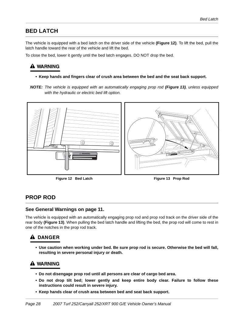
BED LATCH
The vehicle is equipped with a bed latch on the driver side of the vehicle (Figure 12). To lift the bed, pull thelatch handle toward the rear of the vehicle and lift the bed.
To close the bed, lower it gently until the bed latch engages. DO NOT drop the bed.
ý WARNING
• Keep hands and fingers clear of crush area between the bed and the seat back support.
NOTE: The vehicle is equipped with an automatically engaging prop rod (Figure 13), unless equippedwith the hydraulic or electric bed lift option.
PROP ROD
See General Warnings on page 11.The vehicle is equipped with an automatically engaging prop rod and prop rod track on the driver side of therear body (Figure 13). When pulling the bed latch handle and lifting the bed, the prop rod will come to rest inone of the notches in the prop rod track.
ý DANGER
• Use caution when working under bed. Be sure prop rod is secure. Otherwise the bed will fall,resulting in severe personal injury or death.
ý WARNING
• Do not disengage prop rod until all persons are clear of cargo bed area.• Do not drop tilt bed; lower gently and keep entire body clear. Failure to follow these
instructions could result in severe injury.• Keep hands clear of crush area between bed and seat back support.
Figure 12 Bed Latch Figure 13 Prop Rod
LATCH
0PEN
Page 28 2007 Turf 252/Carryall 252/XRT 900 G/E Vehicle Owner’s Manual
Loading and Unloading
To lower the bed, lift the bed so that the prop rod is no longer supported in one of the track notches. Push theprop rod toward the front of the vehicle to free it from the track notch and gently lower the bed. DO NOT dropthe bed.
LOADING AND UNLOADING
ý WARNING
• Firmly engage the park brake before loading the vehicle.• Do not allow riders in the cargo bed.• Do not exceed the rated capacity of the vehicle. Rated capacity is for level surfaces only.• Overloading can affect vehicle handling or cause component failure, resulting in loss of
control of vehicle and possible severe personal injury.• Reduce vehicle load and speed when driving up or down slopes or on uneven terrain. • Reduce speed and avoid sudden stops when backing up. Failure to do so may cause the
vehicle to overturn or flip over backwards.• Avoid stopping on a hill when loaded. If you must stop on a hill, avoid sudden starts, or rolling
backwards and stopping suddenly. Failure to heed this warning may cause vehicle tooverturn, possibly resulting in severe personal injury.
• Do not load the tailgate. The tailgate should be in the upright position and latched securelywhile the vehicle is in motion.
• To help avoid shifting the vehicle load and possibly overturning the vehicle, avoid suddenstarts, sudden stops, and abrupt turns.
• The cargo’s center of gravity may affect the handling, steering, and braking of the vehicle.When the vehicle is loaded, reduce speed and drive slowly in turns.
• To help prevent cargo from shifting and possibly injuring a passenger or affecting thevehicle’s handling, make sure cargo is well secured.
• Avoid top-heavy loads. The center of gravity of a load should never exceed 15 inches (38 cm)above the bottom of the cargo bed.
• Unload cargo bed before raising vehicle with a lift, hoist, or jack.
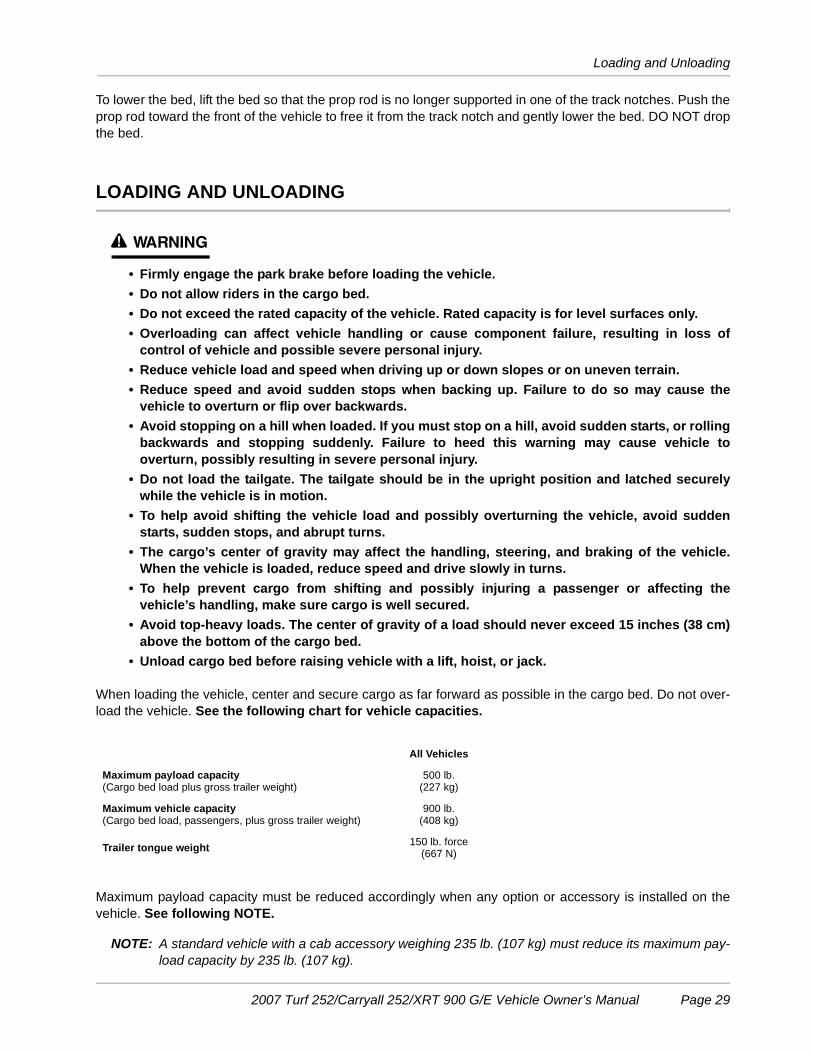
When loading the vehicle, center and secure cargo as far forward as possible in the cargo bed. Do not over-load the vehicle. See the following chart for vehicle capacities.
Maximum payload capacity must be reduced accordingly when any option or accessory is installed on thevehicle. See following NOTE.
NOTE: A standard vehicle with a cab accessory weighing 235 lb. (107 kg) must reduce its maximum pay-load capacity by 235 lb. (107 kg).
All Vehicles
Maximum payload capacity(Cargo bed load plus gross trailer weight)
500 lb.(227 kg)
Maximum vehicle capacity (Cargo bed load, passengers, plus gross trailer weight)
900 lb.(408 kg)
Trailer tongue weight 150 lb. force(667 N)
2007 Turf 252/Carryall 252/XRT 900 G/E Vehicle Owner’s Manual Page 29

Towing with the Vehicle
TOWING WITH THE VEHICLE
ý WARNING
• Do not tow a vehicle or trailer on public streets or highways.• Normal vehicle operating speed should be reduced when towing.• Extreme caution should be used when towing.• Total vehicle capacity, including the tow vehicle load rating and the gross weight of the
vehicle or trailer being towed should not exceed the weight previously specified.• Do not allow riders in the vehicle or trailer being towed.• Avoid sudden starts, sudden stops, and tight turns when towing.• Avoid stopping on a hill when towing. If you must stop on a hill, avoid sudden starts or rolling
backwards and stopping suddenly. Failure to heed this warning could cause the vehicle tooverturn, possibly resulting in severe personal injury.
Because towing a vehicle or trailer can have an adverse effect on vehicle handling, be especially cautiouswhen towing with a Club Car vehicle. See the preceding chart for vehicle capacities.Parking the vehicle with a trailer on a hill should be avoided. If you must park on a hill, apply the brakes andhave someone chock the tires of the trailer. Brakes should be released to allow the chocks to absorb the loadof the trailer. After the tires have been chocked, engage the park brake.
TRANSPORTING ON A TRAILER
ý WARNING
• Do not allow riders in the trailer being towed.• Avoid sudden starts, sudden stops, and tight turns when towing.• Avoid stopping on a hill when towing. If you must stop on a hill, avoid sudden starts or rolling
backwards and stopping suddenly. Failure to heed this warning could cause the vehicle tooverturn, possibly resulting in severe personal injury.
• For use on public roads, the trailer must meet all federal, state, and local requirements suchas taillights, brake lights, etc.
• Reduce normal driving speed when transporting a Club Car vehicle on a trailer.• Do not tow a Club Car vehicle behind a passenger vehicle or truck on a public road unless it is
on an approved trailer.• The vehicle to be transported should be tied securely to the trailer, with the Forward/Reverse
handle or switch in the NEUTRAL position, the key switch in the OFF position, and the parkbrake firmly pressed and locked.
• Because of the added length of the trailer, use caution when making turns.• Do not transport the vehicle on a trailer with a load in the vehicle cargo bed.• Remove the vehicle windshield and secure the seat bottom before transporting on a trailer.• Gasoline vehicles only: Turn the fuel shut-off valve to the closed (OFF) position (Figure 14).
If the vehicle must be transported over long distances or on public highways, it should be transported on anapproved trailer that has a load rating of at least 2000 lb. (909 kg) per vehicle being transported:
Page 30 2007 Turf 252/Carryall 252/XRT 900 G/E Vehicle Owner’s Manual
Storage – Electric Vehicles
NOTE: A two-car trailer should be rated at 2 x 2000 lb. = 4000 lb. (2 x 909 kg = 1818 kg).
STORAGE – ELECTRIC VEHICLES
See General Warnings on page 11.
ý WARNING
• Turn the key switch to the OFF position, remove the key, and leave the Forward/Reversehandle or switch in the NEUTRAL position during storage. This is to prevent unintentionallystarting the vehicle or a fire hazard. Place Tow/Run switch in the TOW position.
• Do not attempt to charge frozen batteries or batteries with bulged cases. Discard the battery.Frozen batteries can explode.
ý CAUTION
• Batteries in a low state of charge will freeze at low temperatures.• To avoid exposing electrical components to moisture and subsequent damage, do not use
any type or pressure washing or steam cleaning equipment to wash the vehicle.
PREPARING THE ELECTRIC VEHICLE FOR EXTENDED STORAGE1. Unload the vehicle so that tires are supporting only the weight of the vehicle.
2. Fully charge batteries. See Charging Batteries on page 44.3. Batteries should be clean and free of corrosion. Wash tops and terminals of batteries with a solution of
baking soda and water (1 cup (237 mL) baking soda per 1 gallon (3.8 L) of water). Rinse solution off bat-teries. Do not allow this solution to enter the batteries. Be sure terminals are tight. Let the terminals dryand then coat them with Battery Terminal Protector Spray (CCI P/N 1014305).
4. Store vehicle in a cool, dry place. This will minimize battery self-discharge.
5. Adjust tires to recommended tire pressure. See Vehicle Specifications – Gasoline Vehicles onpage 52.
6. Perform semiannual periodic lubrication. See Periodic Lubrication Schedules on page 38.7. Thoroughly clean front body, rear body, seats, cargo bed, battery compartment, and underside of vehicle.
8. Do not engage the park brake. Chock the wheels to prevent the vehicle from rolling.
9. Keep batteries fully charged during storage.
• Leave battery chargers plugged in during storage. The onboard computer will automatically activatethe charger when necessary. If charger cannot remain plugged in, or AC power will not be availableduring extended storage, disconnect the batteries for storage (Figure 2, Page 13).
CAUTION
• Be sure to check the batteries and charger monthly to maintain correct battery water level andensure the charger is operating correctly during storage.
RETURNING THE STORED ELECTRIC VEHICLE TO SERVICE1. If necessary, connect batteries and tighten terminals to 110 in-lb (12.4 N·m).
2007 Turf 252/Carryall 252/XRT 900 G/E Vehicle Owner’s Manual Page 31
Storage – Gasoline Vehicles
2. Fully charge batteries.
3. Adjust tires to recommended tire pressure. See Vehicle Specifications – Gasoline Vehicles onpage 52.
4. Perform the Pre-Operation and Daily Safety Checklist on page 23 and the Performance Inspection onpage 30.
STORAGE – GASOLINE VEHICLES
See General Warnings on page 11.
ý DANGER
• Do not attempt to drain gasoline when the engine is hot or while it is running.
• Be sure to clean up any spilled gasoline before operating the vehicle.
• Store gasoline in an approved gasoline container only. Store in a well-ventilated area awayfrom sparks, open flames, heaters, or heat sources.
• Keep gasoline out of the reach of children.
• Do not siphon gasoline from the vehicle.
ý WARNING
• Turn the key switch to the OFF position, remove the key, and leave the Forward/Reversehandle in the NEUTRAL position during storage. This is to prevent unintentionally starting thevehicle or a fire hazard.
• Turn the fuel shut-off valve to the closed (OFF) position (Figure 14).
• Do not attempt to charge frozen batteries or batteries with bulged cases. Discard the battery.Frozen batteries can explode.
ý CAUTION
• Batteries in a low state of charge will freeze at low temperatures.
PREPARING THE GASOLINE VEHICLE FOR EXTENDED STORAGE
1. Unload the vehicle so that tires are supporting only the weight of the vehicle.
2. Store vehicle in a cool, dry place. This will minimize battery self-discharge. If the battery appears to beweak, have it charged by a trained technician. Use an automotive-type 12-volt battery charger rated at10 amps or less.
3. Drain carburetor and seal the fuel tank.
3.1. Pedal-start vehicles: Place the Forward/Reverse handle in the NEUTRAL position and the neutrallockout switch in the MAINTENANCE position. Turn the fuel shut-off valve to the closed (OFF) posi-tion (Figure 14) and run the engine until fuel remaining in the carburetor and fuel lines is depleted
Page 32 2007 Turf 252/Carryall 252/XRT 900 G/E Vehicle Owner’s Manual

Storage – Gasoline Vehicles
and the engine stalls. Return the neutral lockout switch to the OPERATE position.
3.2. Key-start vehicles: Place the Forward/Reverse handle in the NEUTRAL position. Turn the fuelshut-off valve to the closed (OFF) position (Figure 14) and run the engine until fuel remaining in thecarburetor and fuel lines is depleted and the engine stalls.
3.3. Loosen, but do not remove, the carburetor drain screw and drain fuel remaining in bowl into a small,clean container, then pour the fuel from the container into vehicle fuel tank. Tighten the carburetordrain screw.
3.4. Fill fuel tank to about 1 inch (2.5 cm) from top of fuel tank and, following manufacturer’s directions,add a commercially available fuel stabilizer (such as Sta-Bil®).
3.5. Disconnect fuel vent line from fuel tank vent nipple.3.6. Plug the fuel tank vent nipple so that it is air tight. We recommend using a slip-on vinyl cap.
4. Disconnect the battery cables, negative (–) cable first.
5. Batteries should be clean and free of corrosion. Wash tops and terminals of batteries with a solution ofbaking soda and water (1 cup (237 mL) baking soda per 1 gallon (3.8 L) of water). Rinse solution off bat-teries. Do not allow this solution to enter the batteries. Be sure terminals are tight. Let the terminals dryand then coat them with Battery Terminal Protector Spray (CCI P/N 1014305).
6. To protect the engine, remove spark plug and pour 1/2 ounce (14.2 mL) of SAE 10 weight oil into theengine through the spark plug hole. Rotate engine crankshaft by hand several times and then install thespark plug.
7. Adjust tires to recommended tire pressure. See Vehicle Specifications – Gasoline Vehicles onpage 52.
8. Perform semiannual periodic lubrication. See Periodic Lubrication Schedules on page 38.
9. Thoroughly clean front body, rear body, seats, cargo bed, engine compartment, and underside of vehicle.
10. Do not engage the park brake. Chock the wheels to prevent the vehicle from rolling.
RETURNING THE STORED GASOLINE VEHICLE TO SERVICE1. Restore fuel system to operation.
1.1. Remove plug from the fuel tank vent (Figure 30, Page 50). 1.2. Connect vent tube to fuel tank vent.
Figure 14 Fuel Shut-off Valve – Closed Position
CLOSED (OFF) POSITION(SELECTOR IS ALIGNED
WITH OFF MARKINGS ON THE SIDES OF VALVE)
OFFOFF
VIEWED FROM SELECTOR SIDE OF VALVE
2007 Turf 252/Carryall 252/XRT 900 G/E Vehicle Owner’s Manual Page 33
Maintenance
2. Connect battery cables, positive (+) cable first, and tighten terminals to 12 ft-lb (16 N·m).
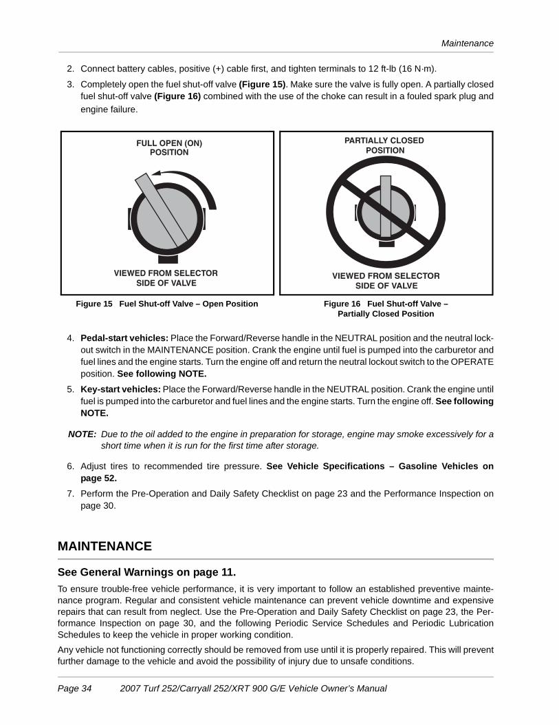
3. Completely open the fuel shut-off valve (Figure 15). Make sure the valve is fully open. A partially closedfuel shut-off valve (Figure 16) combined with the use of the choke can result in a fouled spark plug andengine failure.
4. Pedal-start vehicles: Place the Forward/Reverse handle in the NEUTRAL position and the neutral lock-out switch in the MAINTENANCE position. Crank the engine until fuel is pumped into the carburetor andfuel lines and the engine starts. Turn the engine off and return the neutral lockout switch to the OPERATEposition. See following NOTE.
5. Key-start vehicles: Place the Forward/Reverse handle in the NEUTRAL position. Crank the engine untilfuel is pumped into the carburetor and fuel lines and the engine starts. Turn the engine off. See followingNOTE.
NOTE: Due to the oil added to the engine in preparation for storage, engine may smoke excessively for ashort time when it is run for the first time after storage.
6. Adjust tires to recommended tire pressure. See Vehicle Specifications – Gasoline Vehicles onpage 52.
7. Perform the Pre-Operation and Daily Safety Checklist on page 23 and the Performance Inspection onpage 30.
MAINTENANCE
See General Warnings on page 11.To ensure trouble-free vehicle performance, it is very important to follow an established preventive mainte-nance program. Regular and consistent vehicle maintenance can prevent vehicle downtime and expensiverepairs that can result from neglect. Use the Pre-Operation and Daily Safety Checklist on page 23, the Per-formance Inspection on page 30, and the following Periodic Service Schedules and Periodic LubricationSchedules to keep the vehicle in proper working condition.Any vehicle not functioning correctly should be removed from use until it is properly repaired. This will preventfurther damage to the vehicle and avoid the possibility of injury due to unsafe conditions.
Figure 15 Fuel Shut-off Valve – Open Position Figure 16 Fuel Shut-off Valve –Partially Closed Position
VIEWED FROM SELECTOR SIDE OF VALVE
FULL OPEN (ON)POSITION
VIEWED FROM SELECTOR SIDE OF VALVE
PARTIALLY CLOSEDPOSITION
Page 34 2007 Turf 252/Carryall 252/XRT 900 G/E Vehicle Owner’s Manual
Periodic Service Schedules
Contact your local Club Car distributor/dealer to perform all repairs and semiannual and annual periodic ser-vice.
ý WARNING
• If any problems are found during scheduled inspection or service, do not operate the vehicleuntil repairs are made. Failure to make necessary repairs could result in fire, propertydamage, severe personal injury, or death.
• Hot! Do not attempt to service hot engine, motor, or exhaust system. Attempting to do socould cause severe burns.
• Do not work on vehicle powertrain or under the cargo bed when it is loaded.• Do not wear loose clothing or jewelry, such as rings, watches, chains, etc., when servicing the
vehicle.• Turn the key switch to OFF, remove the key, place the Forward/Reverse handle or switch in the
NEUTRAL position, and chock tires prior to servicing.• Be sure all persons are clear of the vehicle when lifting a cargo bed equipped with a tailgate
ramp.• Do not remove prop rod or close bed until all persons are clear of the bed area. Lower the bed
gently, keeping entire body clear. do not drop the bed. Failure to follow these instructionscould result in severe personal injury.
• A hydraulic bed lift system is under pressure. Wear a face shield and use extreme cautionwhen servicing it.
Gasoline vehicles only:• Moving parts: Do not attempt to service gasoline vehicle while the engine is running.• Turn the fuel shut-off valve to the closed (OFF) position (Figure 14, Page 33).• To avoid unintentionally starting the vehicle, before servicing always disconnect the battery,
negative (–) cable first (Figure 1, Page 13) and disconnect the spark plug wire from the spark plug.
• Frame ground – Do not allow tools or other metal objects to contact frame whendisconnecting batteries or other electrical wiring. Never allow a positive wire to touch thevehicle frame, engine, or other metal component.
PERIODIC SERVICE SCHEDULES
See General Warnings on page 11.
ý WARNING
• Service, repairs, and adjustments must be made per instructions in the maintenance andservice manual.
NOTE: If the vehicle is constantly hauling heavy loads or hauling a trailer, these preventive maintenanceprocedures should be performed more often than recommended in the Periodic Service Schedule.
Both the Periodic Service Schedules and the Periodic Lubrication Schedules must be followed tokeep vehicle in optimum operating condition.
2007 Turf 252/Carryall 252/XRT 900 G/E Vehicle Owner’s Manual Page 35

Periodic Service Schedules
PERIODIC SERVICE SCHEDULE – ELECTRIC VEHICLES
REGULAR INTERVAL SERVICE
Daily service by owner Batteries Charge batteries (after each use only).
Brake System Check brakes per Performance Inspection on page 23. Adjust brakes as required.
Weekly service by owner Batteries Check electrolyte level. Add water if necessary. See page 41.
Monthly service by owneror trained technician Batteries Wash battery tops and clean terminals
with baking soda/water solution.
TiresCheck air pressure and adjust if necessary. See Vehicle Specifications – Gasoline Vehicles on page 52.
General vehicle Wash battery compartment and underside of vehicle.
Semiannual service by trained technician only(or every 50 hours of operation, whichever comes first)
Brake system
Check brake shoes; replace if necessary or adjust as required.See Section 6 – Wheel Brake Assemblies in the appropriate maintenance and service manual.
Lubricate brake slides per Lubrication Schedule. See Section 6 – Wheel Brake Assemblies in the appropriate maintenance and service manual.
Check brake cables for damage; replace if necessary.
Electrical wiring and connections Check for tightness and damage.
Forward/Reverse switchCheck condition of contacts and wire connections; make sure connections are tight.
Front wheel alignment and camber
Check and adjust as required. See Section 7 – Steering and Front Suspension in the appropriate maintenance and service manual.
Motor Controller Output Regulator (MCOR)
Check for loose hardware, cracks, or other damage.
Annual service bytrained technician only(or every 100 hours of operation, whichever comes first)
BatteriesIf batteries are not performing as expected, see Section 13 – Batteries in the maintenance and service manual.
Page 36 2007 Turf 252/Carryall 252/XRT 900 G/E Vehicle Owner’s Manual

Periodic Service Schedules
PERIODIC SERVICE SCHEDULE – GASOLINE VEHICLES
REGULAR INTERVAL SERVICE
Daily service by owner Brake System Check brakes per Performance Inspection on page 23. Adjust brakes as required.
Monthly service by owneror trained technician
Engine
Check engine oil level; change if necessary. See Periodic Lubrication Schedules on page 38. Dispose of used oil properly.
Check engine cooling air intake; visually inspect unshrouded area around engine exhaust for grass and debris, and clean if necessary.
TiresCheck air pressure and adjust if necessary. See Vehicle Specifications – Gasoline Vehicles on page 52.
General vehicle Wash engine compartment and undersideof vehicle. Do not wash engine when hot.
Semiannual service by trained technician only(or every 50 hours of operation, whichever comes first)
BatteryClean terminals and wash dirt from casing; check electrolyte level.See page 46.
Front wheel alignment and camber
Check and adjust if necessary.See Section 7 – Steering and Front Suspension in the appropriate maintenance and service manual.
Electrical wiring and connections Check for tightness and damage.
Brake system
Check brake shoes; replace if necessary or adjust as required.See Section 6 – Wheel Brake Assemblies in the appropriate maintenance and service manual.
Lubricate brake slides per Lubrication Schedule. See Section 6 – Wheel Brake Assemblies in the appropriate maintenance and service manual.
Check brake cables for damage; replace as required.
Annual service bytrained technician only(or every 100 hours of operation, whichever comes first)
Engine
Check for leaks around gaskets, fill plugs, etc.
Inspect, clean and gap spark plug; replace if necessary.
Engine air intake system
Check air filter element; clean or replace if necessary.
Check clamps for tightness; check hose for cracks.
General vehicle Check for loose hardware and tighten if necessary.
Two year service by trained technician only(or every 200 hours of operation, whichever come first)
Fuel filters Replace. Dispose of used filters properly.
2007 Turf 252/Carryall 252/XRT 900 G/E Vehicle Owner’s Manual Page 37

Periodic Lubrication Schedules
ý WARNING
• If any problems are found during scheduled inspection or service, do not operate the vehicleuntil repairs are made. Failure to make necessary repairs could result in fire, propertydamage, severe personal injury, or death.
PERIODIC LUBRICATION SCHEDULES
PERIODIC LUBRICATION SCHEDULE – ELECTRIC VEHICLES
REGULAR INTERVAL SERVICE LUBRICATIONPOINTS RECOMMENDED LUBRICANT
Semiannually by owneror trained technician (or every 50 hours of operation, whichevercomes first)
Brake pedal shaft bearings Dry Moly Lube (CCI P/N 1012151)
Brake linkage and pivots Dry Moly Lube (CCI P/N 1012151)
Accelerator pivot rod supports Dry Moly Lube (CCI P/N 1012151)
Brake slides Dry Moly Lube (CCI P/N 1012151)
Front suspension (5 fittings) Chassis Lube – EP NLGI Grade 2
Annually by trainedtechnician only (or every 100 hours of operation, whichevercomes first)
Check/fill transaxle to plug level 22 oz. (0.67 liters) SAE 30 WT. API Class SE, SF, or SG Oil (or higher)
Inspect front wheel bearings(Repack as necessary) Chassis Lube – EP NLGI Grade 2
Figure 17 Lubrication Points – Electric Vehicles
1
2
3
5
6
7
8
FLOORBOARD
**
13
1
6 6
8
8
7
32
6
6
2 6
5
55
5
4
Page 38 2007 Turf 252/Carryall 252/XRT 900 G/E Vehicle Owner’s Manual

Periodic Lubrication Schedules
PERIODIC LUBRICATION SCHEDULE – GASOLINE VEHICLES
REGULAR INTERVAL SERVICE LUBRICATIONPOINTS RECOMMENDED LUBRICANT
Semiannually by owneror trained technician(or every 50 hours of operation, whichever comes first)
Brake pedal shaft bearings Dry Moly Lube (CCI P/N 1012151)
Brake linkage and pivots Dry Moly Lube (CCI P/N 1012151)
Accelerator pivot rod supports and shifter cable pivots Dry Moly Lube (CCI P/N 1012151)
Front suspension (5 fittings) Chassis Lube (EP NLGI Grade 2)
Brake slides Dry Moly Lube (CCI P/N 1012151)
Annually by trainedtechnician only (or every 100 hours of operation, whichever comes first)
Check/fill unitized transaxle to plug level
27 oz. (.8 liters) 80-90 WT. API Class GL-3 or 80-90 WT. AGMA Class EP Gear Lube
Inspect front wheel bearings(Repack as necessary) Chassis Lube – EP NLGI Grade 2
First change 100 hours –additional change every 200 hours of operation or annually, whichever comes first
Change engine oil and oil filter32 oz. (.95 liters) without filter; 38 oz. (1.12 liters) with filter. (Figure 29, Page 49)
Figure 18 Lubrication Points – Gasoline Vehicles
1
2
3
4
5
6
7
8
4
4
4
2
2
1
1
7
74
3
86
3
FLOORBOARD
4
3
5
53
5
5
2007 Turf 252/Carryall 252/XRT 900 G/E Vehicle Owner’s Manual Page 39

Vehicle Controller – Electric Vehicles
VEHICLE CONTROLLER – ELECTRIC VEHICLES
The Club Car electric vehicle is equipped with a solid state speed controller. In order to properly service andmaintain the solid state controller vehicle, it is necessary to understand the electrical circuitry and the func-tions of all components in the system. Therefore, if any repair or servicing needs to be performed, we recom-mend that it be performed by an authorized Club Car distributor/dealer using Club Car OEM parts.
BATTERIES – ELECTRIC VEHICLES
See General Warnings on page 11.
ý DANGER
• Battery – Explosive gases! Do not smoke. Keep sparks and flames away from the vehicle andservice area. Ventilate when charging or operating vehicle in an enclosed area. Wear a fullface shield and rubber gloves when working on or near batteries.
• Charge batteries in a well-ventilated area only. Batteries emit hydrogen while being charged.Hydrogen is an explosive gas and must never exceed a level of 2% of the air.
• Battery – Poison! Contains acid! Causes severe burns. Avoid contact with skin, eyes, orclothing. Antidotes:- External: Flush with water. Call a physician immediately.- Internal: Drink large quantities of milk or water followed with milk of magnesia or vegetable
oil. Call a physician immediately.- Eyes: Flush with water for 15 minutes. Call a physician immediately.
ý WARNING
• Wear safety glasses or approved eye protection when servicing the vehicle or battery charger.Wear a full face shield and rubber gloves when working on or near batteries.
• Use insulated tools when working near batteries or electrical connections. Use extremecaution to avoid shorting of components or wiring.
• Ensure battery connections are clean and properly tightened. See Battery Care on page 41.• Use only 4-gauge (AWG) wires with low-resistance terminals to replace battery wires on IQ
Plus models.
CAUTION
• Turn off all accessories before charging batteries.
NOTE: Recycle or dispose of discarded batteries in accordance with local, state, and federal regulations.
Club Car electric vehicles use deep-cycle batteries. Automotive batteries should never be used in electricvehicles.
New batteries will not deliver their full capabilities until they have been discharged and recharged 20 to 50times. To obtain maximum service life from new batteries, restrict the use of vehicles with new batteries to onehour of operation between charges for the first two months vehicle is in service. Batteries should be fullycharged before first use of new vehicle, before first use of a vehicle after storage, and before releasing vehiclefor use each day.
Page 40 2007 Turf 252/Carryall 252/XRT 900 G/E Vehicle Owner’s Manual
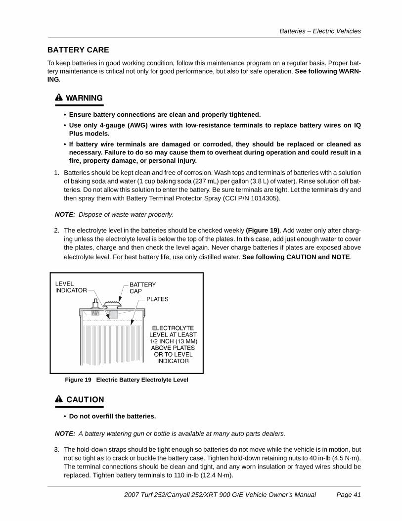
Batteries – Electric Vehicles
BATTERY CARETo keep batteries in good working condition, follow this maintenance program on a regular basis. Proper bat-tery maintenance is critical not only for good performance, but also for safe operation. See following WARN-ING.
ý WARNING
• Ensure battery connections are clean and properly tightened.• Use only 4-gauge (AWG) wires with low-resistance terminals to replace battery wires on IQ
Plus models.• If battery wire terminals are damaged or corroded, they should be replaced or cleaned as
necessary. Failure to do so may cause them to overheat during operation and could result in afire, property damage, or personal injury.
1. Batteries should be kept clean and free of corrosion. Wash tops and terminals of batteries with a solutionof baking soda and water (1 cup baking soda (237 mL) per gallon (3.8 L) of water). Rinse solution off bat-teries. Do not allow this solution to enter the battery. Be sure terminals are tight. Let the terminals dry andthen spray them with Battery Terminal Protector Spray (CCI P/N 1014305).
NOTE: Dispose of waste water properly.
2. The electrolyte level in the batteries should be checked weekly (Figure 19). Add water only after charg-ing unless the electrolyte level is below the top of the plates. In this case, add just enough water to coverthe plates, charge and then check the level again. Never charge batteries if plates are exposed aboveelectrolyte level. For best battery life, use only distilled water. See following CAUTION and NOTE.
ý CAUTION
• Do not overfill the batteries.
NOTE: A battery watering gun or bottle is available at many auto parts dealers.
3. The hold-down straps should be tight enough so batteries do not move while the vehicle is in motion, butnot so tight as to crack or buckle the battery case. Tighten hold-down retaining nuts to 40 in-lb (4.5 N·m).The terminal connections should be clean and tight, and any worn insulation or frayed wires should bereplaced. Tighten battery terminals to 110 in-lb (12.4 N·m).
Figure 19 Electric Battery Electrolyte Level
ELECTROLYTELEVEL AT LEAST1/2 INCH (13 MM)ABOVE PLATESOR TO LEVELINDICATOR
PLATES
LEVEL INDICATOR
BATTERYCAP
2007 Turf 252/Carryall 252/XRT 900 G/E Vehicle Owner’s Manual Page 41
Battery Charger – Electric Vehicle
4. After use, the batteries should be placed on charge. The batteries should never be left discharged anylonger than absolutely necessary (do not leave batteries discharged overnight).
BATTERY CHARGER – ELECTRIC VEHICLE
ý DANGER
• The charging area must be ventilated. Hydrogen level in the air must never exceed 2%. Thetotal volume of air in the charging area must be changed five times per hour. Exhaust fansshould be located at the highest point of the roof. Contact a local HVAC engineer.
• Do not charge the vehicle batteries with the vehicle covered or enclosed. Any enclosure orcover should be removed or unzipped and pulled back when batteries are being charged. Anaccumulation of hydrogen gas could result in an explosion.
ý WARNING
• Only trained technicians should repair or service the charger. Contact a Club Car distributor/dealer.
• Each charger should have its own dedicated 15 or 20 ampere separately protected (circuitbreaker or fuse) single phase branch circuit, in accordance with all applicable electrical codesfor the location.
• Be sure wire connections at the receptacle and fuse link are clean and tight.• Have worn, cut, or damaged power cords or wires replaced immediately.• Do not expose to rain or any liquid. Keep the charger dry.• Do not use near fuels, grain dust, solvents, thinners, or other flammables. Chargers can ignite
flammable materials and vapors.• Connect the charger AC supply cord to a properly grounded, three-wire outlet of the proper
voltage and frequency as shown on the charger.• Do not use an adapter to plug the charger with a three-prong plug into a two-prong outlet.
Improper connection of the equipment-grounding conductor can result in a fire or anelectrical shock.
• An extension cord or electrical outlet must accept a three-prong plug. Extension cord shouldbe a three-wire No. 12 AWG (American Wire Gauge) or No. 14 SWG (British Standard WireGauge) and be as short as possible. The use of improper extension cord could result in fire oran electrical shock.
• Do not operate the charger if it has received a sharp blow, was dropped, or otherwisedamaged in any way.
• Do not push objects of any kind into the charger through cabinet slots. They may touchdangerous voltage points or cause an electrical short circuit that could result in fire orelectrical shock.
• Do not connect a stationary charger to the receptacle if the charger cord, plug, or the vehiclereceptacle is broken, damaged in any manner, or does not make a good electrical connection.Fire or personal injury can result. Have a qualified technician repair or replace it immediately.
• When using a stationary charger, do not pull on the DC cord (Figure 21, Page 44). Do not twist,rock, or bend the plug. To disconnect the plug from the receptacle, grasp the plug, not thecord, and slowly pull it straight out of the receptacle (Figure 20, Page 44).
WARNING CONTINUED ON NEXT PAGE...
Page 42 2007 Turf 252/Carryall 252/XRT 900 G/E Vehicle Owner’s Manual

Battery Charger – Electric Vehicle
ý WARNING
• When the charger is ON, the charger DC cord may be disconnected from the vehiclereceptacle slowly. Jerking or pulling the DC cord out quickly could cause arcing and burningthat could damage the plug and receptacle and could cause batteries to explode.
• Do not use a charger if:- The plug is too loose or does not make a good connection.
- The plug and receptacle feel hotter than normal during charge.
- The plug pins or contacts are bent or corroded.
- The plug, receptacle or cords are cut, worn, have any exposed wires, or are damaged in anyway.
• Using a charger with any of the above symptoms could result in fire, property damage,personal injury, or death.
• Do not block or cover the charger ventilation slots. The slots provide ventilation and preventthe charger from overheating.
• Do not allow clothing, blankets, or other material to cover the charger.• Do not allow the charger to operate for more than 30 minutes at 19 or more amperes.• Install surge arrestors on incoming AC power lines. Surge arrestors will help protect electrical
components in the charger and on the vehicle from all but direct or close lightning strikes.
NOTE: Because the vehicle’s onboard computer (OBC) has a storage charge feature that automaticallychecks and recharges the batteries as necessary every 15 days, the charger can remain pluggedto a vehicle throughout the storage period.
At one hour and at two hours into the charge cycle, the charger will shut off in order to run a self-diag-nostic program (ammeter will drop to zero). Charging will resume in a few moments (ammeterreturns to previous rate of charge).
Each electric vehicle is supplied with either a fully automatic, stationary battery charger as standard equip-ment. The AC cord from the charger should be connected to a source capable of supplying 15 amperes min-imum per charger.
To reduce the risk of electric shock, the battery charger must be grounded. The charger is equipped with anAC electric cord having an equipment-grounding conductor and a grounding type plug. The AC plug must beconnected to an appropriate receptacle that is properly installed and grounded in accordance with theNational Electrical Code and all local codes and ordinances. See the owner’s manual supplied with thecharger for specific operating instructions before using the charger.
The use of an extension cord with the charger should be avoided. If an extension cord must be used, use athree-conductor no. 12 AWG (American Wire Gauge) or no. 14 SWG (British Standard Wire Gauge), heavy-duty cord with ground, properly wired and in good electrical condition. Keep it as short as possible (no morethan 12 feet (3.7 m)). Place all cords so they will not be stepped on, tripped over, or otherwise subject to dam-age or stress.
Ensure that the charger ventilation slots are unobstructed and that there is adequate ventilation.
ý WARNING
• Vehicles with a charger receptacle: Never modify wiring to bypass the gray sense lead fuse(Figure 22, Page 45).
2007 Turf 252/Carryall 252/XRT 900 G/E Vehicle Owner’s Manual Page 43
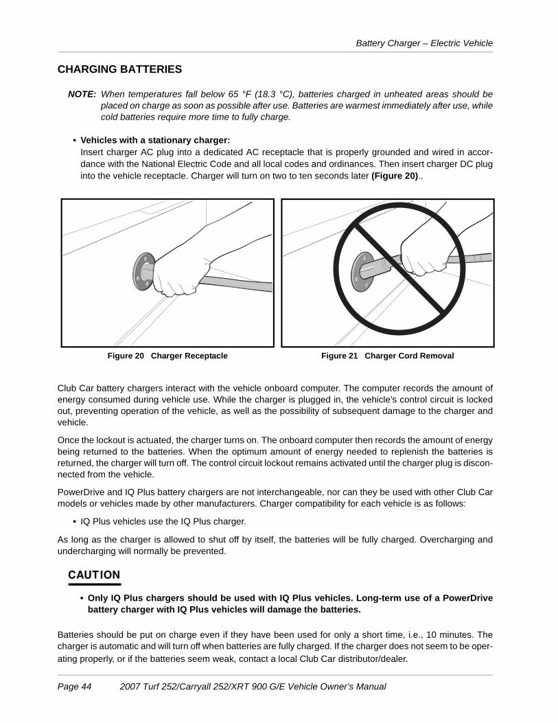
Battery Charger – Electric Vehicle
CHARGING BATTERIES
NOTE: When temperatures fall below 65 °F (18.3 °C), batteries charged in unheated areas should beplaced on charge as soon as possible after use. Batteries are warmest immediately after use, whilecold batteries require more time to fully charge.
• Vehicles with a stationary charger:Insert charger AC plug into a dedicated AC receptacle that is properly grounded and wired in accor-dance with the National Electric Code and all local codes and ordinances. Then insert charger DC pluginto the vehicle receptacle. Charger will turn on two to ten seconds later (Figure 20)..
Club Car battery chargers interact with the vehicle onboard computer. The computer records the amount ofenergy consumed during vehicle use. While the charger is plugged in, the vehicle’s control circuit is lockedout, preventing operation of the vehicle, as well as the possibility of subsequent damage to the charger andvehicle.
Once the lockout is actuated, the charger turns on. The onboard computer then records the amount of energybeing returned to the batteries. When the optimum amount of energy needed to replenish the batteries isreturned, the charger will turn off. The control circuit lockout remains activated until the charger plug is discon-nected from the vehicle.
PowerDrive and IQ Plus battery chargers are not interchangeable, nor can they be used with other Club Carmodels or vehicles made by other manufacturers. Charger compatibility for each vehicle is as follows:
• IQ Plus vehicles use the IQ Plus charger.
As long as the charger is allowed to shut off by itself, the batteries will be fully charged. Overcharging andundercharging will normally be prevented.
CAUTION
• Only IQ Plus chargers should be used with IQ Plus vehicles. Long-term use of a PowerDrivebattery charger with IQ Plus vehicles will damage the batteries.
Batteries should be put on charge even if they have been used for only a short time, i.e., 10 minutes. Thecharger is automatic and will turn off when batteries are fully charged. If the charger does not seem to be oper-ating properly, or if the batteries seem weak, contact a local Club Car distributor/dealer.
Figure 20 Charger Receptacle Figure 21 Charger Cord Removal
Page 44 2007 Turf 252/Carryall 252/XRT 900 G/E Vehicle Owner’s Manual
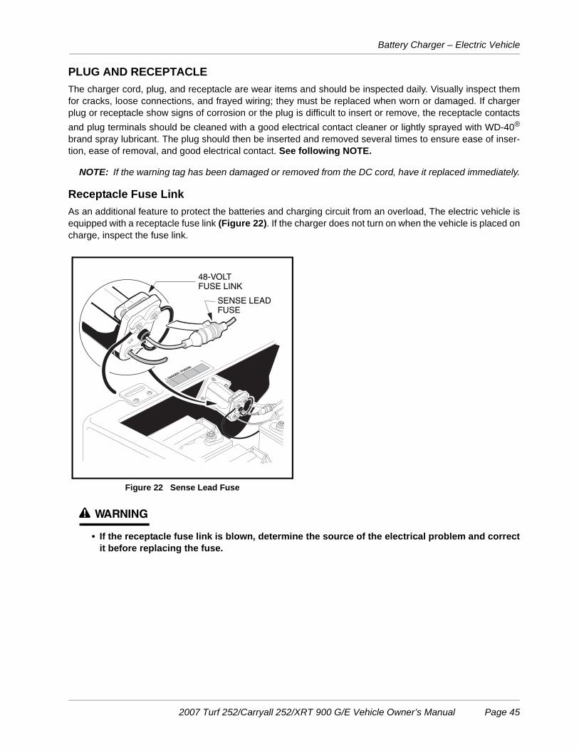
Battery Charger – Electric Vehicle
PLUG AND RECEPTACLEThe charger cord, plug, and receptacle are wear items and should be inspected daily. Visually inspect themfor cracks, loose connections, and frayed wiring; they must be replaced when worn or damaged. If chargerplug or receptacle show signs of corrosion or the plug is difficult to insert or remove, the receptacle contactsand plug terminals should be cleaned with a good electrical contact cleaner or lightly sprayed with WD-40®
brand spray lubricant. The plug should then be inserted and removed several times to ensure ease of inser-tion, ease of removal, and good electrical contact. See following NOTE.
NOTE: If the warning tag has been damaged or removed from the DC cord, have it replaced immediately.
Receptacle Fuse LinkAs an additional feature to protect the batteries and charging circuit from an overload, The electric vehicle isequipped with a receptacle fuse link (Figure 22). If the charger does not turn on when the vehicle is placed oncharge, inspect the fuse link.
ý WARNING
• If the receptacle fuse link is blown, determine the source of the electrical problem and correctit before replacing the fuse.
Figure 22 Sense Lead Fuse
DANGER / POISON
!
SENSE LEADFUSE
48-VOLT FUSE LINK
2007 Turf 252/Carryall 252/XRT 900 G/E Vehicle Owner’s Manual Page 45

Battery – Gasoline Vehicle
BATTERY – GASOLINE VEHICLE
See General Warnings on page 11.
ý DANGER
• Battery – Explosive gases! Do not smoke. Keep sparks and flames away from the vehicle andservice area. Ventilate when charging or operating vehicle in an enclosed area. Wear a fullface shield and rubber gloves when working on or near batteries.
• Follow all instructions carefully when working with batteries.• Charge battery in a well-ventilated area only.• Battery – Poison! Contains acid! Causes severe burns. Avoid contact with skin, eyes, or
clothing. Antidotes:- External: Flush with water. Call a physician immediately.- Internal: Drink large quantities of milk or water followed with milk of magnesia or vegetable
oil. Call a physician immediately.- Eyes: Flush with water for 15 minutes. Call a physician immediately.
ý WARNING
• Do not jump-start a dead battery using another battery and jumper cables.
The battery in a Club Car gasoline vehicle is a 12-volt, low-maintenance battery that requires infrequentwatering (Figure 23).
Any corrosion around the positive (+) or negative (–) terminals should be washed off with a solution of bakingsoda and water (1 cup (237 mL) per gallon (3.8 L) of water). Rinse solution off the battery. Do not allow thissolution to get into the battery. Be sure terminals are tight (battery terminals should be tightened to 144 in-lb(16 N·m)). Let the terminals dry and then spray them with Battery Terminal Protector Spray (CCI 1014305).See following WARNING.
ý WARNING
• If battery wire terminals are damaged or corroded, they should be replaced or cleaned asnecessary. Failure to do so may cause them to overheat during operation and could result in afire, property damage, or personal injury.
Figure 23 Battery Figure 24 Gasoline Battery Electrolyte Level
ELECTROLYTE LEVEL AT LEAST 1/2 INCH (13 MM)
ABOVE PLATES OR TO LEVEL
INDICATOR
PLATESLEVEL
INDICATOR
BATTERYCAP
Page 46 2007 Turf 252/Carryall 252/XRT 900 G/E Vehicle Owner’s Manual

Engine Oil – Gasoline Vehicle
Be sure battery clamp is properly tightened. Tighten to 144 in-Ib (16 N·m). A loose clamp may allow the bat-tery to become damaged from vibration or jarring.
If battery appears weak, have it charged by a trained technician. The battery should never be left dischargedany longer than absolutely necessary (do not leave discharged overnight).
ENGINE OIL – GASOLINE VEHICLE
Even though the low oil warning light on the dash should illuminate if oil level becomes low, engine oil levelshould be checked monthly. Vehicle should be on a level surface when checking oil. Do not overfill with oil.
ENGINE OIL LEVEL CHECK1. Remove the oil level dipstick from the oil filler tube, and wipe oil off dipstick (1) (Figure 25). See follow-
ing CAUTION.
CAUTION
• Do not remove dipstick while engine is running.
2. Check oil by fully inserting the dipstick into the oil filler tube (2) and immediately removing it.
3. If the oil level is at or below the low level mark on the dipstick gauge, add oil until the level is betweenlow and full levels (safe level) (3).
4. Insert the dipstick into the oil filler tube. See following NOTE.
NOTE: Properly recycle or dispose of used oil in accordance with local, state, and federal regulations.
ENGINE OIL AND FILTER CHANGEEngine oil and oil filter should be changed after the first 100 hours of operation. After that, they should bechanged every 200 hours of operation or annually, whichever comes first.
1. Turn the key switch to the OFF position, then remove the key. Place the Forward/Reverse handle in theneutral POSITION. Chock the front wheels.
2. Access the engine compartment.
Figure 25 Engine Oil Level Check
LowLevel
SafeLevel
FullLevel
1
2
3
2007 Turf 252/Carryall 252/XRT 900 G/E Vehicle Owner’s Manual Page 47
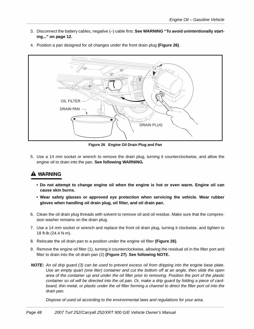
Engine Oil – Gasoline Vehicle
3. Disconnect the battery cables, negative (–) cable first. See WARNING “To avoid unintentionally start-ing...” on page 12.
4. Position a pan designed for oil changes under the front drain plug (Figure 26).
5. Use a 14 mm socket or wrench to remove the drain plug, turning it counterclockwise, and allow theengine oil to drain into the pan. See following WARNING.
ý WARNING
• Do not attempt to change engine oil when the engine is hot or even warm. Engine oil cancause skin burns.
• Wear safety glasses or approved eye protection when servicing the vehicle. Wear rubbergloves when handling oil drain plug, oil filter, and oil drain pan.
6. Clean the oil drain plug threads with solvent to remove oil and oil residue. Make sure that the compres-sion washer remains on the drain plug.
7. Use a 14 mm socket or wrench and replace the front oil drain plug, turning it clockwise, and tighten to18 ft-lb (24.4 N·m).
8. Relocate the oil drain pan to a position under the engine oil filter (Figure 26).
9. Remove the engine oil filter (1), turning it counterclockwise, allowing the residual oil in the filter port andfilter to drain into the oil drain pan (2) (Figure 27). See following NOTE.
NOTE: An oil drip guard (3) can be used to prevent excess oil from dripping into the engine base plate.Use an empty quart (one liter) container and cut the bottom off at an angle, then slide the openarea of the container up and under the oil filter prior to removing. Position the port of the plasticcontainer so oil will be directed into the oil pan. Or, make a drip guard by folding a piece of card-board, thin metal, or plastic under the oil filter forming a channel to direct the filter port oil into thedrain pan.
Dispose of used oil according to the environmental laws and regulations for your area.
Figure 26 Engine Oil Drain Plug and Pan
OIL FILTER
DRAIN PAN
DRAIN PLUG
Page 48 2007 Turf 252/Carryall 252/XRT 900 G/E Vehicle Owner’s Manual

Engine Oil – Gasoline Vehicle
10. Use a clean rag and wipe the oil filter mounting bracket surface clean where the oil filter gasket seats.
11. Install a new oil filter (CCI P/N 1016467) onto the engine oil filter port. Apply a light coat of white lithiumNLGI Number 2 grease (Dow Corning® BR2-Plus or equivalent) or new engine oil to the rubber sealaround the outside surface of the filter before attaching it to the oil filter port (Figure 28). This will helpseal the filter to the oil mounting bracket.
NOTE: Use only Club Car oil filters (CCI P/N 1016467) designed for this engine.
12. Tighten the oil filter by hand until tight. Do not use a band wrench or channel lock plier to tighten.
13. Remove the dipstick and add engine oil into the dipstick port. Use a funnel or pour spout to direct the oilinto the dipstick port. With filter change, the engine requires 38 ounces (1.12 liters) of oil per change.Refer to oil viscosity guidelines for selection of oil grade (Figure 29). Replace the dipstick.
14. Connect the battery cables, positive (+) cable first, and tighten terminals to 12 ft-lb (16 N·m). Coat ter-minals with Battery Terminal Protector Spray (CCI P/N 1014305).
Figure 27 Remove Engine Oil Filter
Figure 28 Coat Oil Filter Rubber Seal Figure 29 Oil Viscosity Chart
1
2
3
SAE 5W-30
SAE 10W-30/ SAE 10W-40
SAE 30
SAE 40
2007 Turf 252/Carryall 252/XRT 900 G/E Vehicle Owner’s Manual Page 49

Fueling Instructions – Gasoline Vehicle
15. With the Forward/Reverse handle in the NEUTRAL position, start and run the engine for a few minutes.Observe both the drain plug and the oil filter from under the vehicle and watch for oil leaks. If leaksappear, begin with step 1 and repeat the appropriate step for either or both items to correct the problem.
16. Remove the dip stick and check the engine oil as a final step. Replace the dip stick.
FUELING INSTRUCTIONS – GASOLINE VEHICLE
See General Warnings on page 11.
ý DANGER
• Turn the key switch to the OFF position before fueling.• Do not pour gasoline into the fuel tank when the engine is hot or while it is running.• To avoid electric arc caused by static electricity, the fuel storage/pumping device must be
grounded. If the pump is not grounded, the vehicle must be grounded to the pump before andduring the fueling operation.
• If the vehicle has an all-weather enclosure installed, be sure the fuel tank is properly vented asshown (Figure 30).
• To avoid the possibility of fire, clean up any spilled gasoline before operating the vehicle.
ý CAUTION
• To allow for expansion, do not fill higher than one inch from top of the fuel tank. Avoid spilling fuel.
NOTE: Whenever possible, avoid using oxygenated fuels and fuels that are blended with alcohol. Vehiclesto be stored for extended periods should be prepared for storage as instructed. See Preparing theGasoline Vehicle for Extended Storage on page 32.
1. Remove the fuel cap located on the passenger-side side panel and fill the fuel tank with fresh unleadedgasoline only. See preceding CAUTION and NOTE.
2. Replace fuel cap on tank. Ensure cap is tightened securely.
Figure 30 Fuel Tank
FUELSHUT-OFFVALVE
TO CARBURETOR
VENT TUBES
FUEL TANK
VENT
Page 50 2007 Turf 252/Carryall 252/XRT 900 G/E Vehicle Owner’s Manual

Cleaning the Vehicle
CLEANING THE VEHICLE
The vehicles are equipped with an ArmorFlex® front body, an all-aluminum rear body, and either an aluminumor powder-coated steel cargo bed. Use only commercially available automotive cleaners with a sponge or softcloth for normal cleaning. A garden hose at normal residential water pressure is adequate. To remove oxida-tion or discoloration from aluminum, use a commercially available aluminum cleaner paste and fine grade(No. 00) steel wool.
Club Car does not recommend any type of pressure washer or steam cleaning. Such a process will exposeelectrical components to moisture. Moisture entering electrical components can result in water damage andsubsequent component failure.
Use non-abrasive wax products. Battery acid, fertilizers, tars, asphalt, creosote, paint, or chewing gum shouldbe removed immediately to prevent possible stains.
The seats of the vehicle will last longer with proper cleaning. Use a solution of 10% liquid soap and warmwater applied with a soft cloth. For imbedded dirt, a soft bristle brush may be used. For heavy soiling, difficultstains or scratches, blemishes, or other body damage, see Section 4 of the Turf/Carryall Maintenance andService Manual.
NOTE: Dispose of waste water properly.
ACCESSORIES
There is a complete line of accessory equipment available from Club Car and our dealers/distributors. Youcan obtain the name and phone number of your closest Club Car contact by visiting our web site at www.club-car.com and clicking the “Dealer Locator” link.
Care should be taken that these accessories are properly installed by trained technicians, and they are usedin the manner for which they were designed. See following WARNING.
ý WARNING
• Custom cab assemblies, weatherproof enclosures, door kits, and tinted windshields will notprotect occupants from flying objects.
• If the vehicle has a portable refreshment center option installed in the bed, it must be removedbefore unlatching and lifting the bed.
• If the vehicle is equipped with an electric powered lift bed, remove the bed before servicingthe bed lift system.
SUBSEQUENT OWNER REGISTRATION
In the event a vehicle is bought as a used vehicle, we strongly urge the new owner to register the vehicle withClub Car. This will enable us to contact you if the need arises. Please send your name, address, and serialnumber(s) of the vehicle(s) to Club Car, Inc., P.O. Box 204658, Augusta, Georgia 30917-4658, Attention:Vehicle Registration.
2007 Turf 252/Carryall 252/XRT 900 G/E Vehicle Owner’s Manual Page 51

Vehicle Specifications – Gasoline Vehicles
VEHICLE SPECIFICATIONS – GASOLINE VEHICLES
SPECIFICATIONS XRT 900Gasoline
Turf 252Carryall 252
Gasoline
POWER SOURCE
Engine: 4 cycle, OHV, 351 cc, 11.5 maximum hp @ 3600 rpm (per SAE J 1940/1349), single cylinder, air cooled, with pressure lubrication system • •
Fuel system: Side-draft carburetor with float bowl, fixed jets, fuel filters, and impulse fuel pump • •
Governor: Automatic ground-speed sensing, internally geared in unitized transaxle • •
Ignition: Transistor electronic ignition with electronic RPM limiter • •
Unitized transaxle: Fully synchronized forward and reverse with neutral (11.8:1 forward, 17.1:1 reverse) • •
Electrical system: 12 volt, 500 cca at 0 °F (–17.8 °C), 650 at 32 °F (0 °C). 105-minute reserve capacity and 35-amp charging capacity • •
Torque converter: Automatic, variable-speed, dry type • •
STEERING/SUSPENSION/BRAKES
Steering: Self-adjusting rack and pinion • •
Suspension: Front and rear multi-leaf springs with dual hydraulic shocks • •
Brakes: Mechanical brake cable system to manually adjusted drum brakes on each wheel withautomatic-release park brake • •
BODY/CHASSIS
Frame/Chassis: Twin I-Beam welded aluminum • •
Side and rear body: All aluminum with a powder-coated steel box bed •
Side and rear body: All aluminum •
Front body: ArmorFlex® • •
Front body finish: Matched paint finish over molded-in color • •
Tires: Heavy Duty All Terrain: tubeless, 6-ply rated Turf: tubeless, 4-ply rated
22 x 11.00 x 10 in.23 x 10.50 x 12 in.
DIMENSIONS/WEIGHT
Overall length 120.4 in. (305 cm)
Overall width 51.3 in. (130 cm)
Overall height (at steering wheel) 51.1 in. (129 cm)
Overall height (at light bar) 75.3 in. (191 cm)
Wheelbase 78.5 in. (199 cm)
Ground clearance (under differential) 6.4 in. (16 cm)
Ground clearance (under foot platform) 11.0 in. (27.9 cm)
Front wheel tread 36.5 in. (92 cm)
Rear wheel tread 41.3 in. (104 cm)
Weight (standard vehicle with off-road tires (dry)) 937 lb. (425 kg)
Forward speed 17-19 mph (27-31 km/h) 15-17 mph (24-27 km/h)
Governed RPM 3100 ±30 2900 ±30
Curb clearance circle (diameter) 21 ft.-8 in. (660 cm)
Turning radius (per SAE J 695) 130 in. (330 cm)
Load bed height 29.8 in. (75 cm)
Load bed size (box bed inside dimensions)48.0 x 49.8 x 10.9 in.(121.9 x 126 x 28 cm)
(15.3 cubic feet)
48.8 x 49.8 x 10.9 in.(124 x 126 x 28 cm)
(15.3 cubic feet)
Page 52 2007 Turf 252/Carryall 252/XRT 900 G/E Vehicle Owner’s Manual

Vehicle Specifications – Gasoline Vehicles
Floorboard height 16.0 in. (40 cm)
Seat height (at seat bottom) 28.0 in. (71 cm)
Vehicle rated capacity (level surface only) 900 lb. (408 kg)
Bed load capacity (level surface only) 500 lb. (227 kg)
Standard seating capacity 2
LIQUID CAPACITIES
Engine crankcase without filter 32 oz. (.95 liters)
Engine crankcase with filter 38 oz. (1.12 liters)
Unitized transaxle 27 oz. (.8 liters)
Fuel tank 7 gallons (26.5 liters)
TIRE PRESSURE
Off-road tread 14-18 psi (.97-1.24 Bars)
Turf tread 18-20 psi (1.24-1.38 Bars)
SPECIFICATIONS XRT 900Gasoline
Turf 252Carryall 252
Gasoline
2007 Turf 252/Carryall 252/XRT 900 G/E Vehicle Owner’s Manual Page 53

Vehicle Specifications – Electric Vehicles
VEHICLE SPECIFICATIONS – ELECTRIC VEHICLES
SPECIFICATIONS XRT 900Electric
Turf 252Carryall 252
Electric
POWER SOURCE
Drive motor: Direct drive, 48 volts DC, shunt wound, 3.7 hp • •
Transaxle: Double reduction helical gear with 12.3:1 direct drive axle • •
Electrical system: 48 volts DC, reduced speed reverse • •
Batteries: High capacity, deep cycle, Trojan 6-volt, 160 min. capacity • •
Charger: Automatic, 17 amp; UL and CSA listed • •
STEERING/SUSPENSION/BRAKES
Steering: Self-adjusting rack and pinion • •
Suspension: Front mono-leaf and rear multi-leaf springs with dual hydraulic shocks • •
Brakes: Mechanical brake cable system to manually-adjusted drum brakes on all four wheels. Park brake is automatically released. Self-adjusting multi-latch ratchet and pawl • •
BODY/CHASSIS
Frame/chassis: Twin I-Beam welded aluminum • •
Side and rear body: All aluminum with a powder-coated steel box bed •
Side and rear body: All aluminum •
Front body: ArmorFlex® • •
Front body finish: Matched paint finish over molded-in color • •
Tires: Heavy Duty All Terrain: tubeless, 6-ply rated Turf: tubeless, 4-ply rated • •
DIMENSIONS/WEIGHT
Overall length: Standard flatbed configuration 120.4 in.(305 cm)
Overall width ] 51.3 in.(130 cm)
Overall height: At steering wheel 51.1 in.(129 cm)
Wheelbase 78.5 in.(199 cm)
Ground clearance (under differential) 6.4 in.(16 cm)
Ground clearance (under foot platform) 11.0in.(27.9 cm)
Front wheel tread 36.5 in.(92 cm)
Rear wheel tread 41.3 in.(104 cm)
Weight: Standard electric vehicle 1322 lb. (600 kg) 1322 lb. (600 kg)
Forward speed 17-19 mph(27-31 km/h)
15-17 mph(24-27 km/h)
Curb clearance circle (diameter) 21 ft.-8 in.(660 cm)
Turning radius per SAE J 695 130 in.(330 cm)
Load bed height 31.5 in.(80 cm)
Page 54 2007 Turf 252/Carryall 252/XRT 900 G/E Vehicle Owner’s Manual

Vehicle Specifications – Electric Vehicles
Load bed size (box bed inside dimensions)48.0 x 49.8 x 10.9 in.(121.9 x 126 x 28 cm)
(15.3 cubic feet)
48.8 x 49.8 x 10.9 in.(124 x 126 x 28 cm)
(15.3 cubic feet)
Floorboard height 16.0 in.(40 cm)
Seat height 28.0 in.(71 cm)
Vehicle rated capacity: Level surface only 900 lb.(408 kg)
Bed load capacity (level surface only) 500 lb. (227 kg)
Standard seating capacity 2
LIQUID CAPACITIES
Transaxle 22 oz.(0.67 liters)
TIRE PRESSURE
Off-road tread 14-18 psi (.97-1.24 Bars)
Turf tread 18-20 psi (1.24-1.38 Bars)
SPECIFICATIONS XRT 900Electric
Turf 252Carryall 252
Electric
2007 Turf 252/Carryall 252/XRT 900 G/E Vehicle Owner’s Manual Page 55

Rear Fender Installation
REAR FENDER INSTALLATION
1. Unload the cargo bed.
2. Open the cargo bed and engage the prop rod.
ý WARNING
• Use caution when working under bed. Be sure prop rod is secure. Otherwise the bed couldfall, resulting in severe personal injury or death.
NOTE: The rear fender with the warning decal should be installed on the passenger side of the vehicle.The decal should be plainly visible when the cargo bed is raised.
3. Position a fender in the vehicle, align the hole in the fender with the slot in the frame as shown and installbolt (1), large flat washers (2), and locknut (3) (Figure 31). Finger-tighten only at this time.
Figure 31 Install Hardware in Fender Hole
HOLES TO BE DRILLED
1
3
2
2
Front of
Vehicle
DRIVER SIDE SHOWN
Page 56 2007 Turf 252/Carryall 252/XRT 900 G/E Vehicle Owner’s Manual

Rear Fender Installation
4. Make sure fender is correctly aligned in the vehicle by placing the outer fender rib to the outside of theupper side panel, and as far forward as possible, leaving no gap between the fender and side panel(Figure 32).
5. Drill three 5/16-inch holes through the fender: two through the outside holes in the front mountingbracket, and one through the slotted hole in the top mounting bracket (Figure 32).
6. Loosely install bolts (1), large flat washers (2), small flat washers (4), and locknuts (3) in the front mount-ing bracket holes.
7. Install bolt (1), large flat washer (2), small flat washer (4) and locknut (3) in the top mounting bracket holeas shown (Figure 32).
8. Tighten mounting hardware at both front mounting bracket holes, then both top mounting bracket holes,to 35 in-lb (4.0 N·m).
9. Repeat steps 3-8 for the other rear fender.
10. Lower cargo bed.
Figure 32 Drill Additional Mounting Holes
Front of
Vehicle
DRIVER SIDE SHOWN
2
4
32 1
3 4
1
Before drilling holes, move fender as far forward as possible.
Do not allow any gapbetween fender and side panel.
UPPER SIDE PANEL
TOP MOUNTING BRACKET
FRONT MOUNTING BRACKET
Fender rib tooutside ofside panel
2007 Turf 252/Carryall 252/XRT 900 G/E Vehicle Owner’s Manual Page 57
Wheel and Tire Installation
WHEEL AND TIRE INSTALLATION
NOTE: Upon vehicle delivery, the shipping wheel and tire assemblies must be replaced by the standardwheel and tire assemblies, which are delivered in the vehicle cargo bed.
Do not remove the warning tag attached to the steering wheel until the shipping wheel and tireassemblies have been replaced by standard wheel and tire assemblies.
The front and rear wheels are NOT interchangeable. The rear wheels have a different offset than do the frontwheels; the rear wheels must be installed with the deeper offset facing out.
A rectangular sticker on each wheel designates its correct location on the vehicle.
LF —Left Front (driver side)
RF—Right Front (passenger side)
LR—Left Rear
RR—Right Rear
Standard tires (off-road) are directional and must be installed according to the directional arrow mark on eachtire, (arrow indicates forward rotation of tire) or tread performance will be severely compromised. The optionalturf tire is not directional, and installation is dictated only by correct wheel position, not tire direction.
1. Slightly loosen the lug nuts on all four wheels.
2. Raise one end of the vehicle until the tires are off the ground by approximately six inches. See followingWARNING.
ý WARNING
• Lift only one end of a vehicle at a time. Before lifting, set the park brake when lifting the frontof the vehicle, unload the cargo bed, and chock the wheels that remain on the floor. Use asuitable lifting device (chain hoist or hydraulic floor jack) with 1000 lb. (454 kg) minimumlifting capacity. Do not use lifting device to hold vehicle in raised position. Use approved jackstands of proper weight capacity to support vehicle.
3. Remove the lug nuts and the wheel.
4. Install the correct wheel and tire assembly and tighten lug nuts (using a crisscross pattern) until they aresnug. Arrow indicates forward rotation of tire.
5. Repeat steps 3 and 4 for the other side of the vehicle.
6. Lower the vehicle to the ground and finish tightening lug nuts (using a crisscross pattern) to 55 ft-lb (74.6N·m).
7. Repeat steps 2 through 6 for the other end of the vehicle.
Page 58 2007 Turf 252/Carryall 252/XRT 900 G/E Vehicle Owner’s Manual
CLUB CAR® LIMITED TWO YEAR WARRANTY FOR 2007TRANSPORTATION AND UTILITY VEHICLES
1. WARRANTY: CLUB CAR, INC., (“CLUB CAR”) hereby warrants to the Original Retail Purchaser that its new 2007 Model Transportationand Utility Vehicles purchased from CLUB CAR or an authorized dealer shall be free from defects in material andworkmanship under normal use and service as a transportation or utility vehicle for the periods stated below, subject to theprovisions, limitations and exclusions contained in this limited warranty.
LIMITED TWO YEAR / 2000 HOUR WARRANTY: The engine assembly, unitized transaxle assembly (gasoline vehicle),motor, transaxle assembly (electric vehicle), main frame assembly, box bed hydraulic dump kit, Custom Cab assembly anddoors, and Driving Range Protective Enclosure are warranted with respect to parts and labor against defects in material andworkmanship for a period of two years or 2000 hours of operation, whichever first occurs, from the date of purchase.
LIMITED ONE YEAR / 1000 HOUR WARRANTY: All remaining components of the vehicle not specified otherwise, thePortable Refreshment Center, and all other original equipment options and accessories supplied by CLUB CAR arewarranted with respect to parts and labor against defects in material and workmanship for a period of one year or 1000hours of operation, whichever first occurs, from the date of purchase.
This limited warranty covers material, workmanship and repair labor cost as to those items specifically listed above for theperiods specified. Such repair labor shall be performed only by CLUB CAR, its authorized dealers, or a service agencyapproved by CLUB CAR.
IF THE WARRANTY REGISTRATION FORM IS NOT COMPLETED AND RETURNED TO CLUB CAR AT THE TIME OFTHE ORIGINAL RETAIL SALE, PURCHASER MUST PROVIDE PROOF OF DATE OF PURCHASE WITH ANYWARRANTY CLAIM.
2. EXCLUSIONS:Excluded from any CLUB CAR warranty are all fuses, filters, decals (except safety decals), spark plugs, light bulbs,lubricants, trim pieces, seats, routine wear items such as the charger plug and receptacle, brake shoes, belts, brushes,bushings, engine mounts, mats and pads, maintenance adjustments, cosmetic deterioration, and items which deteriorate orfail due to exposure or ordinary wear and tear. Batteries, battery charger, onboard computer, and solid-state speedcontroller are covered under separate CLUB CAR warranties. Also excluded from any CLUB CAR warranty is damage to avehicle or component resulting from a cause other than a defect including unreasonable or unintended strain or use,improper installation of accessories, installation of parts or accessories that are not original equipment, overloading,accident, alteration, abuse or neglect.
Transportation expenses for warranty services are also excluded from this warranty.
3. VOIDING OF WARRANTY:THIS AND ANY OTHER WARRANTY SHALL BE VOID IF THE VEHICLE IS ABUSED OR USED IN AN UNINTENDEDMANNER OR SHOWS INDICATIONS THAT IT HAS BEEN ALTERED IN ANY WAY, INCLUDING, BUT NOT LIMITED TO,MODIFICATION OF THE SPEED GOVERNOR, BRAKING SYSTEM, STEERING, TRANSAXLE, OR OTHEROPERATING SYSTEMS OF THE VEHICLE TO CAUSE IT TO PERFORM OUTSIDE CLUB CAR SPECIFICATIONS. THEWARRANTY IS LIKEWISE VOID IF THE VEHICLE INVOLVED SHOWS INDICATIONS THAT REASONABLE ORNECESSARY MAINTENANCE AS OUTLINED IN THE OWNER’S MANUAL AND MAINTENANCE AND SERVICEMANUAL WAS NOT PERFORMED AT THE TIME AND IN THE MANNER SPECIFIED IN SUCH MANUALS.
4. SOLE REMEDY:CLUB CAR’s liability under this limited warranty, or in any action whether based upon warranty, contract, negligence, strictproduct liability or otherwise, shall be the repair or replacement, at CLUB CAR’s option, of the vehicle or component thereofthat CLUB CAR deems to be defective. Replacement shall mean furnishing, during the applicable limited warranty period, anew vehicle or factory-reconditioned vehicle or component thereof that is identical or reasonably equivalent to the warrantedproduct or component at no cost to the purchaser. Repair shall mean remedying a defect in the vehicle or componentthereof at no cost to the purchaser during the applicable limited warranty period. If CLUB CAR elects to repair the vehicle, itmay provide factory-reconditioned parts or components. All parts and components replaced under warranty shall becomethe property of CLUB CAR.
5. HOW TO MAKE A WARRANTY CLAIM:To make a warranty claim under this limited warranty, you must present the vehicle or defective component to an authorizedCLUB CAR dealer or send the defective component, freight prepaid, to WARRANTY SERVICES, CLUB CAR, INC., 4125Washington Road, Evans, Georgia 30809, U.S.A., 706-863-3000.
2007 Turf 252/Carryall 252/XRT 900 G/E Vehicle Owner’s Manual Page 59
6. DISCLAIMER:THIS LIMITED WARRANTY IS EXCLUSIVE. CLUB CAR MAKES NO OTHER WARRANTY OF ANY KIND,EXPRESSED OR IMPLIED. ANY IMPLIED WARRANTIES OF MERCHANTABILITY OR FITNESS FOR A PARTICULARPURPOSE WHICH EXCEED THE OBLIGATIONS OR TIME LIMITS STATED IN THIS WARRANTY ARE HEREBYDISCLAIMED BY CLUB CAR AND EXCLUDED FROM THIS WARRANTY. THE PURCHASER AND CLUB CAREXPRESSLY AGREE THAT THE REMEDY OF THE REPLACEMENT OR REPAIR OF THE DEFECTIVE VEHICLE ORCOMPONENT THEREOF IS THE SOLE REMEDY OF THE PURCHASER. CLUB CAR MAKES NO OTHERREPRESENTATION OR WARRANTY OF ANY KIND, AND NO REPRESENTATIVE, EMPLOYEE, OR DEALER OFCLUB CAR HAS THE AUTHORITY TO MAKE OR IMPLY ANY REPRESENTATION, PROMISE OR AGREEMENT,WHICH IN ANY WAY VARIES THE TERMS OF THIS WARRANTY.
7. NO CONSEQUENTIAL DAMAGES:IN NO EVENT SHALL CLUB CAR BE LIABLE FOR ANY INCIDENTAL OR CONSEQUENTIAL DAMAGESINCLUDING, BUT NOT LIMITED TO, LOSS RELATED TO PROPERTY OTHER THAN THE VEHICLE, LOSS OF USE,LOSS OF TIME, INCONVENIENCE, OR ANY OTHER ECONOMIC LOSS.Some states allow neither limitation on the duration of an implied warranty nor exclusions or limitation of incidental orconsequential damages. Therefore, the above limitations or exclusions may not apply to you.
This warranty gives you specific legal rights, and you may also have other rights, which vary from state to state.
8. INFORMATION:For further information contact WARRANTY SERVICES, CLUB CAR, INC., P.O. Box 204658, Augusta, Georgia 30917-4658, U.S.A., 706-863-3000.
9. WARNING:Any modification or alteration of any vehicle beyond factory specifications, including those that affect the weight distribution,stability, or speed of the vehicle, can cause serious personal injury or death.
CLUB CAR® LIMITED FOUR YEAR WARRANTY FOR 2007UTILITY T-105 6-VOLT BATTERIES
CLUB CAR, INC., ("CLUB CAR") hereby warrants to the original retail purchaser that the new "Trojan T-105" 6-Volt Batteryinstalled in its new electric utility vehicle purchased from CLUB CAR or an authorized distributor or dealer will be free fromdefects in material and workmanship and will provide for a period of four years or 18,000 energy units whichever occursfirst, subject to the terms and conditions contained herein.
This limited warranty only covers defects in material and workmanship for a period of four years or 18,000 energy units fromdate of purchase. The terms of this limited four year warranty shall be as follows:
Free replacement with respect to parts and labor within four years or 18,000 energy units, whichever first occurs, from dateof purchase.
The battery should be returned to an authorized CLUB CAR distributor or dealer with evidence of proof of purchase date.CLUB CAR reserves the right to test and recharge any battery returned for adjustment.
LIMITED WARRANTY EXCLUSIONSTHE PROVISIONS OF THIS LIMITED WARRANTY SHALL NOT APPLY TO FAILURE DUE TO:
1) Abuse such as overcharging, undercharging, improper fluid levels, loose wiring, or rusted or corroded hardware;
2) Lack of proper maintenance as outlined in the electric vehicle owner's manual;
3) Damages caused by improper installation of the battery;
4) Neglect, breakage, freezing, fire, explosion, wreckage, the addition of any chemical, or the operation of the battery in anuncharged condition (below half charge - 1,200 specific gravity);
5) A battery damaged by a defective charger.
Without limiting the generality of the foregoing in any way, and as part of its limited warranty exclusion, CLUB CAR does notwarrant that its battery is suitable for use in any application other than in its products. As in the use of any battery, a prudentowner will read and study the charger owner's manual, the electric vehicle owner's manual, the operator instructions, andthe battery warning labels; and will exercise due care in working on or around batteries.
Page 60 2007 Turf 252/Carryall 252/XRT 900 G/E Vehicle Owner’s Manual

Transportation expenses for warranty services are also excluded from this warranty.
WARRANTY LIMITATIONSCLUB CAR's liability under this limited warranty shall be to replace a defective battery. Replacement shall be furnishing anew or used battery with sufficient life to complete the remainder of the warranty term, which is identical or reasonablyequivalent to the warranted product at no cost to the purchaser during the four years or 18,000 energy units warrantyperiod, whichever first occurs. All batteries, which are replaced under this limited warranty, become the property of CLUBCAR.
THIS LIMITED WARRANTY IS EXCLUSIVE. CLUB CAR MAKES NO OTHER WARRANTY OF ANY KIND,EXPRESSED OR IMPLIED. ANY IMPLIED WARRANTIES OF MERCHANTABILITY OR FITNESS FOR APARTICULAR PURPOSE WHICH EXCEED THE OBLIGATIONS OR TIME LIMITS STATED IN THIS WARRANTY AREHEREBY DISCLAIMED BY CLUB CAR AND EXCLUDED FROM THIS WARRANTY. THE PURCHASER AND CLUBCAR EXPRESSLY AGREE THAT THE REPLACEMENT OR REPAIR OF THE DEFECTIVE VEHICLE OR COMPONENTTHEREOF IS THE SOLE REMEDY OF THE PURCHASER. CLUB CAR MAKES NO OTHER REPRESENTATION ORWARRANTY OF ANY KIND AND NO REPRESENTATIVE, EMPLOYEE, DISTRIBUTOR OR DEALER OF CLUB CARHAS THE AUTHORITY TO MAKE OR IMPLY ANY REPRESENTATION, PROMISE OR AGREEMENT, WHICH IN ANYWAY VARIES THE TERMS OF THIS WARRANTY.This battery is intended to be used by persons with training and experience with batteries and only in CLUB CAR electricvehicles. Any other use renders the Limited Warranties expressed herein and all implied warranties null and void and sameare hereby excluded.
ALSO EXCLUDED FROM THIS LIMITED WARRANTY ARE ANY AND ALL INCIDENTAL OR CONSEQUENTIALDAMAGES INCLUDING, BUT NOT LIMITED TO, LOSS OF USE OR REVENUE, LOSS OF TIME, INCONVENIENCE ORANY OTHER ECONOMIC LOSS.Damage not resulting from a defect in material or workmanship or that occurs due to abuse or neglect (including failure toprovide reasonable and necessary maintenance), accident or alteration is excluded from this limited warranty.
Some states allow neither limitation on the duration of an implied warranty nor exclusions or limitations of incidental orconsequential damages. Therefore, the above limitations or exclusions may not apply to you.
This warranty gives you specific legal rights, and you may also have other rights, which vary from states to states.
For further information contact WARRANTY SERVICES, CLUB CAR, INC., P.O. Box 204658, Augusta, Georgia, 30917-4658, U.S.A., 706-863-3000.
CLUB CAR® LIMITED FOUR YEAR WARRANTY FOR 2007UTILITY T-145 6-VOLT BATTERIES
CLUB CAR, INC., ("CLUB CAR") hereby warrants to the original retail purchaser that the new "Trojan T-145" 6-Volt Batteryinstalled in its new electric utility vehicle purchased from CLUB CAR or an authorized distributor or dealer will be free fromdefects in material and workmanship and will provide for a period of four years or 20,000 energy units whichever occursfirst, subject to the terms and conditions contained herein.
This limited warranty only covers defects in material and workmanship for a period of four years or 20,000 energy units fromdate of purchase. The terms of this limited four year warranty shall be as follows:
Free replacement with respect to parts and labor within four years or 20,000 energy units, whichever first occurs, from dateof purchase.
The battery should be returned to an authorized CLUB CAR distributor or dealer with evidence of proof of purchase date.CLUB CAR reserves the right to test and recharge any battery returned for adjustment.
LIMITED WARRANTY EXCLUSIONSTHE PROVISIONS OF THIS LIMITED WARRANTY SHALL NOT APPLY TO FAILURE DUE TO:
1) Abuse such as overcharging, undercharging, improper fluid levels, loose wiring, or rusted or corroded hardware;
2) Lack of proper maintenance as outlined in the electric vehicle owner's manual;
3) Damages caused by improper installation of the battery;
4) Neglect, breakage, freezing, fire, explosion, wreckage, the addition of any chemical, or the operation of the battery in anuncharged condition (below half charge - 1,200 specific gravity);
2007 Turf 252/Carryall 252/XRT 900 G/E Vehicle Owner’s Manual Page 61
5) A battery damaged by a defective charger.
Without limiting the generality of the foregoing in any way, and as part of its limited warranty exclusion, CLUB CAR does notwarrant that its battery is suitable for use in any application other than in its products. As in the use of any battery, a prudentowner will read and study the charger owner's manual, the electric vehicle owner's manual, the operator instructions, andthe battery warning labels; and will exercise due care in working on or around batteries.
Transportation expenses for warranty services are also excluded from this warranty.
WARRANTY LIMITATIONSCLUB CAR's liability under this limited warranty shall be to replace a defective battery. Replacement shall be furnishing anew or used battery with sufficient life to complete the remainder of the warranty term, which is identical or reasonablyequivalent to the warranted product at no cost to the purchaser during the four years or 20,000 energy units warrantyperiod, whichever first occurs. All batteries, which are replaced under this limited warranty, become the property of CLUBCAR.
THIS LIMITED WARRANTY IS EXCLUSIVE. CLUB CAR MAKES NO OTHER WARRANTY OF ANY KIND,EXPRESSED OR IMPLIED. ANY IMPLIED WARRANTIES OF MERCHANTABILITY OR FITNESS FOR APARTICULAR PURPOSE WHICH EXCEED THE OBLIGATIONS OR TIME LIMITS STATED IN THIS WARRANTY AREHEREBY DISCLAIMED BY CLUB CAR AND EXCLUDED FROM THIS WARRANTY. THE PURCHASER AND CLUBCAR EXPRESSLY AGREE THAT THE REPLACEMENT OR REPAIR OF THE DEFECTIVE VEHICLE OR COMPONENTTHEREOF IS THE SOLE REMEDY OF THE PURCHASER. CLUB CAR MAKES NO OTHER REPRESENTATION ORWARRANTY OF ANY KIND AND NO REPRESENTATIVE, EMPLOYEE, DISTRIBUTOR OR DEALER OF CLUB CARHAS THE AUTHORITY TO MAKE OR IMPLY ANY REPRESENTATION, PROMISE OR AGREEMENT, WHICH IN ANYWAY VARIES THE TERMS OF THIS WARRANTY.This battery is intended to be used by persons with training and experience with batteries and only in CLUB CAR electricvehicles. Any other use renders the Limited Warranties expressed herein and all implied warranties null and void and sameare hereby excluded.
ALSO EXCLUDED FROM THIS LIMITED WARRANTY ARE ANY AND ALL INCIDENTAL OR CONSEQUENTIALDAMAGES INCLUDING, BUT NOT LIMITED TO, LOSS OF USE OR REVENUE, LOSS OF TIME, INCONVENIENCE ORANY OTHER ECONOMIC LOSS.Damage not resulting from a defect in material or workmanship or that occurs due to abuse or neglect (including failure toprovide reasonable and necessary maintenance), accident or alteration is excluded from this limited warranty.
Some states allow neither limitation on the duration of an implied warranty nor exclusions or limitations of incidental orconsequential damages. Therefore, the above limitations or exclusions may not apply to you.
This warranty gives you specific legal rights, and you may also have other rights, which vary from states to states.
For further information contact WARRANTY SERVICES, CLUB CAR, INC., P.O. Box 204658, Augusta, Georgia, 30917-4658, U.S.A., 706-863-3000.
CLUB CAR® LIMITED FOUR YEAR WARRANTY FOR 2007 IQ PLUS BATTERY CHARGERS
CLUB CAR, INC., (“CLUB CAR”) hereby warrants to the original retail purchaser that its new IQ Plus Chargers purchasedfrom CLUB CAR or an authorized distributor or dealer will be free from defects in material and workmanship under normaluse and service for a period of four years from the date of purchase, subject to the terms, provisions, limitations, andexclusions contained herein.
The limited warranty with respect to parts and labor only covers defects in material and workmanship for a period of fouryears from the date of purchase. Such repair labor shall be performed only by CLUB CAR or by an authorized distributor ordealer. Purchaser shall be responsible for all freight costs to and from CLUB CAR’s facility.
LIMITED WARRANTY EXCLUSIONSTHE PROVISIONS OF THIS LIMITED WARRANTY SHALL NOT APPLY TO FAILURE DUE TO:
1) Lack of normal maintenance services such as preventive maintenance checks and tightening loose wire connections;
2) Semiconductor parts such as diodes and fuses which are vulnerable to electrical overloads (including lightning) beyondthe control of CLUB CAR;
3) Charger DC cord set with plug, which is a wear item and subject to user abuse.
Page 62 2007 Turf 252/Carryall 252/XRT 900 G/E Vehicle Owner’s Manual

Any warranty service, which includes labor during the first year, must be performed by CLUB CAR or by an authorizeddistributor or dealer. For repairs made by qualified technicians other than CLUB CAR’s factory technicians or an authorizeddistributor or dealer, CLUB CAR will provide only the replacement parts or components.
The IQ Plus Chargers are intended to be used by persons with knowledge of the chargers and proper charging practicesand only on CLUB CAR IQ Plus vehicles. Any other use renders the Limited Warranties expressed herein and any impliedwarranties null and void and same are hereby excluded.
Without limiting the generality of the foregoing in any way, and as part of its limited warranty exclusion, CLUB CAR does notwarrant that the IQ Plus Charger is suitable for use in any application other than its IQ Plus products. As in the use of anyelectrical device, a prudent owner will read and study the charger owner’s manual, the electric vehicle owner’s manual, theoperator instructions, and the battery warning labels; and will exercise due care in working on or around electrical devices.
Transportation expenses for warranty services are also excluded from this warranty.
WARRANTY LIMITATIONSCLUB CAR’s liability under this limited warranty, or in any action whether based upon warranty, contract, negligence, strictproduct liability or otherwise, shall be the replacement or repair of a charger or component thereof that CLUB CAR deemsto be defective. Replacement shall mean furnishing, during the applicable limited warranty period, a new charger orcomponent thereof that is identical or reasonably equivalent to the warranted product or defective component at no cost tothe purchaser. Repair shall mean remedying a defect in the charger or component thereof at no cost to the purchaser duringthe applicable limited warranty period. If CLUB CAR elects to repair the charger, it may provide factory-reconditioned partsor components. All parts and components replaced under warranty shall become the property of CLUB CAR.
THIS LIMITED WARRANTY IS EXCLUSIVE. CLUB CAR MAKES NO OTHER WARRANTY OF ANY KIND,EXPRESSED OR IMPLIED. ANY IMPLIED WARRANTIES OF MERCHANTABILITY OR FITNESS FOR A PARTICULARPURPOSE WHICH EXCEED THE OBLIGATIONS OR TIME LIMITS STATED IN THIS WARRANTY ARE HEREBYDISCLAIMED BY CLUB CAR AND EXCLUDED FROM THIS WARRANTY. THE PURCHASER AND CLUB CAREXPRESSLY AGREE THAT THE REPLACEMENT OR REPAIR OF THE DEFECTIVE VEHICLE OR COMPONENTTHEREOF IS THE SOLE REMEDY OF THE PURCHASER. CLUB CAR MAKES NO OTHER REPRESENTATION ORWARRANTY OF ANY KIND AND NO REPRESENTATIVE, EMPLOYEE, DISTRIBUTOR OR DEALER OF CLUB CARHAS THE AUTHORITY TO MAKE OR IMPLY ANY REPRESENTATION, PROMISE OR AGREEMENT, WHICH IN ANYWAY VARIES THE TERMS OF THIS WARRANTY.IN NO EVENT SHALL CLUB CAR BE LIABLE FOR ANY INCIDENTAL OR CONSEQUENTIAL DAMAGES INCLUDING,BUT NOT LIMITED TO, LOSS RELATED TO PROPERTY OTHER THAN THE BATTERY CHARGER, LOSS OF USE,LOSS OF TIME, INCONVENIENCE, OR ANY OTHER ECONOMIC LOSS.Damage not resulting from a defect that occurs due to unreasonable use, abuse or neglect (including failure to providereasonable or necessary maintenance), accident or alteration is excluded from the limited warranty.
Some states allow neither limitation on the duration of an implied warranty nor exclusions or limitations of incidental orconsequential damages. Therefore, the above limitations or exclusions may not apply to you.
This warranty gives you specific legal rights, and you may also have other rights, which vary from state to state.
For further information contact WARRANTY SERVICES, CLUB CAR, INC., P.O. Box 204658, Augusta, Georgia 30917-4658, U.S.A., 706-863-3000
CLUB CAR® LIMITED FOUR YEAR WARRANTY FOR 2007ONBOARD COMPUTERS AND SOLID STATE SPEED CONTROLLERS
CLUB CAR, INC., (“CLUB CAR”) hereby warrants to the original retail purchaser that the new Onboard Computer and theSolid State Speed Controller, hereinafter called “Computer” and “Controller” respectively, installed in its new electric vehicleequipped with the PowerDrive® System 48™, PowerDrive Plus®, IQ System™, or IQ Plus system and purchased fromCLUB CAR or an authorized distributor or dealer will be free from defects in material and workmanship for a period of fouryears or 800 rounds, whichever first occurs, from the date of purchase subject to the terms and conditions contained herein.
This limited warranty only covers defects in material and workmanship for a period of four years or 800 golf car rounds fromdate of purchase. The terms of this four-year or 800 round limited warranty shall be as follows:
Vehicles used for golf, free replacement with respect to parts and labor within four years or 800 rounds, whichever firstoccurs, from date of purchase.
2007 Turf 252/Carryall 252/XRT 900 G/E Vehicle Owner’s Manual Page 63
Vehicles used for purposes other than golf, free replacement with respect to parts and labor within four years or 16,000energy units as recorded by the Computer, whichever first occurs, from date of purchase.
The Computer or Controller should be returned to an authorized CLUB CAR distributor or dealer with evidence of proof ofpurchase date and number of rounds, freight prepaid. CLUB CAR reserves the right to test any Computer returned forwarranty and to verify number of rounds played by accessing information contained in the Computer.
LIMITED WARRANTY EXCLUSIONS
THE PROVISIONS OF THIS LIMITED WARRANTY SHALL NOT APPLY TO FAILURE DUE TO:
1) Abuse or neglect, such as improper battery fluid levels, loose wiring, or rusted or corroded hardware;
2) Lack of proper maintenance as outlined in the electric vehicle owner’s manual;
3) Damages caused by improper installation of the Computer or Controller;
4) Vehicles charged by systems other than the CLUB CAR PowerDrive Charger.
Without limiting the generality of the foregoing in any way, and as part of its limited warranty exclusion, CLUB CAR does notwarrant that the Computer or Controller is suitable for use in any application other than its PowerDrive System 48,PowerDrive Plus, and IQ System products. As in the use of any battery operated device, a prudent owner will read andstudy the charger owner’s manual, the electric vehicle owner’s manual, the operator instructions, and the battery warninglabels; and will exercise due care in working on or around batteries.
Transportation expenses for warranty services are also excluded from this warranty.
WARRANTY LIMITATIONS:
CLUB CAR’s liability under this limited warranty shall be to replace a defective Computer or Controller. Replacement shallbe furnishing a new or reconditioned Computer or Controller that is identical or reasonably equivalent to the warrantedproduct at no cost to the purchaser during the four-year or 800 round limited warranty period for golf use or 4 years or16,000 energy units for use other than golf, whichever first occurs, except for transportation expenses. All parts andcomponents replaced under this limited warranty become the property of CLUB CAR.
THIS LIMITED WARRANTY IS EXCLUSIVE. CLUB CAR MAKES NO OTHER WARRANTY OF ANY KIND,EXPRESSED OR IMPLIED. ANY IMPLIED WARRANTIES OF MERCHANTABILITY OR FITNESS FOR A PARTICULARPURPOSE WHICH EXCEED THE OBLIGATIONS OR TIME LIMITS STATED IN THIS WARRANTY ARE HEREBYDISCLAIMED BY CLUB CAR AND EXCLUDED FROM THIS WARRANTY. THE PURCHASER AND CLUB CAREXPRESSLY AGREE THAT THE REPLACEMENT OR REPAIR OF THE DEFECTIVE VEHICLE OR COMPONENTTHEREOF IS THE SOLE REMEDY OF THE PURCHASER. CLUB CAR MAKES NO OTHER REPRESENTATION ORWARRANTY OF ANY KIND AND NO REPRESENTATIVE, EMPLOYEE, DISTRIBUTOR OR DEALER OF CLUB CARHAS THE AUTHORITY TO MAKE OR IMPLY ANY REPRESENTATION, PROMISE OR AGREEMENT, WHICH IN ANYWAY VARIES THE TERMS OF THIS WARRANTY.
This computer or controller is intended to be used only in CLUB CAR PowerDrive System 48, PowerDrive Plus, and IQSystem electric vehicles. Any other use renders the Limited Warranties expressed herein and all implied warranties null andvoid and same are hereby excluded.
ALSO EXCLUDED FROM THIS LIMITED WARRANTY ARE ANY AND ALL INCIDENTAL OR CONSEQUENTIALDAMAGES INCLUDING, BUT NOT LIMITED TO, LOSS OF USE OR REVENUE, LOSS OF TIME, INCONVENIENCE ORANY OTHER ECONOMIC LOSS.
Damage not resulting from a defect in material or workmanship or that occurs due to abuse or neglect (including failure toprovide reasonable and necessary maintenance), accident or alteration is excluded from this limited warranty.
Some states allow neither limitation on the duration of an implied warranty nor exclusions or limitations of incidental orconsequential damages. Therefore, the above limitations or exclusions may not apply to you.
This warranty gives you specific legal rights, and you may also have other rights, which vary from state to state.
For further information contact WARRANTY SERVICES, CLUB CAR, INC., P.O. Box 204658, Augusta, Georgia, 30917-4658, U.S.A., 706-863-3000.
Page 64 2007 Turf 252/Carryall 252/XRT 900 G/E Vehicle Owner’s Manual
CALIFORNIA EMISSION CONTROL WARRANTY STATEMENT
Your new Club Car, Inc. ("CLUB CAR") vehicle engine complies with both the U.S. EPA and State of California emission regulations.
YOUR WARRANTY RIGHTS AND OBLIGATIONS:The California Air Resources Board ("CARB") and CLUB CAR are pleased to explain the emission control system warranty on your 2007 vehicle engine. In California, new small off-roadengines (SORE) must be designed, built and equipped to meet the State's stringent anti-smog standards. CLUB CAR must warrant the emission control system on the vehicle engine forthe periods of time listed below provided there has been no abuse, neglect or improper maintenance of your small off-road engine.Your emission control system may include parts such as the carburetor or fuel-injection system, the ignition system, and catalytic converter. Also included may be hoses, belts,connectors and other emission-related assemblies.Where a warrantable condition exists, CLUB CAR will repair your vehicle engine at no cost to you including diagnosis, parts and labor.
MANUFACTURER'S WARRANTY COVERAGE:This emission control system is warranted for two years. If any emission-related part on your equipment is defective, the part will be repaired or replaced by CLUB CAR.
OWNER'S WARRANTY RESPONSIBILITIES:- As the vehicle engine owner, you are responsible for the performance of the required maintenance listed in your owner's manual. CLUB CAR recommends that you retain all receiptscovering maintenance on your vehicle engine, but CLUB CAR cannot deny warranty solely for the lack of receipts or for your failure to ensure the performance of all scheduledmaintenance.- As the vehicle engine owner, you should however be aware that CLUB CAR may deny you warranty coverage if vehicle engine or a part has failed due to abuse, neglect, impropermaintenance or unapproved modifications.- You are responsible for presenting vehicle engine to a CLUB CAR distribution center as soon as a problem exists. The warranty repairs should be completed in a reasonable amount oftime, not to exceed 30 days.If you have any questions regarding your warranty rights and responsibilities, you should contact WARRANTY SERVICES, CLUB CAR, INC., P.O. Box 204658, Augusta, Georgia309017-4658, U.S.A., 1-706-863-3000.
CLUB CAR EXPLANATION OF EMISSION CONTROL WARRANTY:1. WARRANTY:CLUB CAR warrants to the ultimate purchaser and each subsequent purchaser that the SORE or equipment is designed, built and equipped so as to conform with all applicableregulations; and free from defects in materials and workmanship that cause the failure of a warranted part to be identical in all material respects to that part as described in CLUB CARsapplication for certification. The warranty period begins on the date the engine or equipment is delivered to an ultimate purchaser or first placed into service. The warranty period is twoyears.
2. COVERAGE:Subject to certain conditions and exclusions as stated below, the warranty on emission-related parts is as follows:(1) Any warranted part that is not scheduled for replacement as required maintenance in the written instructions supplied, is warranted for the warranty period stated above. If the partfails during the period of warranty coverage, the part will be repaired or replaced by CLUB CAR according to subsection (4) below. Any such part repaired or replaced under warranty willbe warranted for the remainder of the period.(2) Any warranted part that is scheduled only for regular inspection in the written instructions supplied is warranted for the warranty period stated above. Any such part repaired orreplaced under warranty will be warranted for the remaining warranty period.(3) Any warranted part that is scheduled for replacement as required maintenance in the written instructions supplied is warranted for the period of time before the first scheduledreplacement date for that part. If the part fails before the first scheduled replacement, the part will be repaired or replaced by CLUB CAR according to subsection (4) below. Any suchpart repaired or replaced under warranty will be warranted for the remainder of the period prior to the first scheduled replacement point for the part.(4) Repair or replacement of any warranted part under the warranty provisions herein must be performed at a warranty station* at no charge to the owner. (5) Notwithstanding the provisions herein, warranty services or repairs will be provided at all of our distribution centers that are franchised to service the subject engines or equipment.(6) The engine or equipment owner will not be charged for diagnostic labor that is directly associated with diagnosis of a defective, emission-related warranted part, provided that suchdiagnostic work is performed at a warranty station*.(7) CLUB CAR is liable for damages to other engine or equipment components proximately caused by a failure under warranty of any warranted part.(8) Throughout the engine or equipment warranty period stated above, CLUB CAR will maintain a supply of warranted parts sufficient to meet the expected demand for such parts.(9) Any replacement part may be used in the performance of any warranty maintenance or repairs and must be provided without charge to the owner. Such use will not reduce thewarranty obligations of CLUB CAR(10) Add-on or modified parts that are not exempted by the Air Resources Board may not be used. The use of any non-exempted add-on or modified parts by the ultimate purchaser willbe grounds for disallowing a warranty claims. CLUB CAR will not be liable to warrant failures of warranted parts caused by the use of a non-exempted add-on or modified part.*CLUB CAR, its authorized dealers, or a service agency approved by CLUB CAR.
ITEMS COVERED BY THIS WARRANTY:The repair or replacement of any warranted part otherwise eligible for warranty coverage may be excluded from such warranty coverage if CLUB CAR demonstrates that the engine orequipment has been abused, neglected, or improperly maintained, and that such abuse, neglect, or improper maintenance was the direct cause of the need for repair or replacement ofthe part. That notwithstanding, any adjustment of a component that has a factory installed, and properly operating, adjustment limiting device is still eligible for warranty coverage. Thefollowing emission warranty parts list are covered:
SYSTEMS COVERED PARTS DESCRIPTIONFuel Metering Carburetor assembly, fuel injection pump, fuel injection nozzle, fuel regulatorExhaust CatalystAir Induction Air filter housing, air filter*, crankcase breather tubeIgnition Flywheel magneto, ignition pulse generator, ignition coil assembly, ignition control module, spark plug cap, spark plug*Positive Crankcase Ventilation (PCV) System PCV valve, oil filler capMisc. Parts Belts, fuel hose, hosing, tubing, fittings, seals, gasket, and clamps associated with the above systemsEmission-related parts will vary between vehicles; therefore, certain vehicles my not include all of the listed parts or may include equivalent parts.
3. EXCLUSIONS:Excluded from this warranty is damage to a vehicle or component resulting from a cause other than a defect including unreasonable or unintended strain or use, improper installation ofaccessories, installation of parts or accessories that are not original equipment, overloading, accident, alteration, abuse or neglect. This warranty covers only those failures resulting fromdefects in material or workmanship.Transportation expenses for warranty services are also excluded from this warranty.
4. VOIDING OF WARRANTY:THIS AND ANY OTHER WARRANTY SHALL BE VOID IF THE VEHICLE IS ABUSED OR USED IN AN UNINTENDED MANNER OR SHOWS INDICATIONS THAT IT HAS BEENALTERED IN ANY WAY, INCLUDING, BUT NOT LIMITED TO, MODIFICATION OF THE SPEED GOVERNOR, BRAKING SYSTEM, STEERING, TRANSAXLE, OR OTHEROPERATING SYSTEMS OF THE VEHICLE TO CAUSE IT TO PERFORM OUTSIDE CLUB CAR SPECIFICATIONS. THE WARRANTY IS LIKEWISE VOID IF THE VEHICLEINVOLVED SHOWS INDICATIONS THAT REASONABLE OR NECESSARY MAINTENANCE AS OUTLINED IN THE OWNERS MANUAL AND MAINTENANCE AND SERVICEMANUAL WAS NOT PERFORMED AT THE TIME AND IN THE MANNER SPECIFIED IN SUCH MANUALS.
5. NO CONSEQUENTIAL DAMAGES:In no event shall Club Car be liable for any incidental or consequential damages including, but not limited to, loss related to property other than the vehicle, loss of use, loss of time,inconvenience, or any other economic loss. This warranty is applicable only where the California or U.S. EPA emission control system warranty regulation is in effect.
6. HOW TO MAKE A WARRANTY CLAIM:To make a warranty claim under this limited warranty, you must present the vehicle or defective component to an authorized CLUB CAR dealer or send the defective component, freightprepaid, to WARRANTY SERVICES, CLUB CAR, INC., 4125 Washington Road, Evans, Georgia 30809, U.S.A., 706-863-3000.IF THE WARRANTY REGISTRATION FORM IS NOT COMPLETED AND RETURNED TO CLUB CAR AT THE TIME OF THE ORIGINAL RETAIL SALE, PURCHASER MUSTPROVIDE PROOF OF DATE OF PURCHASE WITH ANY WARRANTY CLAIM.
2007 Turf 252/Carryall 252/XRT 900 G/E Vehicle Owner’s Manual Page 65

FUEL AND OIL RECOMMENDATIONS
FuelUse only clean, fresh, unleaded regular grade
gasoline.Octane Rating
The octane rating of a gasoline is a measureof its resistance to “knocking”.Use of a mini-mum of 87 octane of the anti-knock index isrecommended.The anti-knock index is posted onservice station pumps in the U.S.A.
Oxygenated FuelIf you use oxygenated fuel (either ethanol orMTBE added to gasoline), be sure it is unleadedand meets the minimum octane rating require-ment.
The following are the EPA approved percent-ages of fuel oxygenates.
ETHANOL:(Ethyl or Grain Alcohol) You mayuse gasoline containing up to 10% ethanol byvolume.
MTBE:(Methyl Tertiary Butyl Ether) You mayuse gasoline containing up to 15% MTBE byvolume.METHANOL:(Methanol or Wood Alcohol) 5% byvolume.
You may use gasoline containing up to 5%methanol by volume, as long as it also containscosolvents and corrosion inhibitors to protectthe fuel system.Gasoline containing more than5% methanol by volume may cause startingand/or performance problems.It may also dam-age metal, rubber, and plastic parts of your fuelsystem.
Engine OilThe following engine oils are recommended.
API Service Classification:SC, SD, SE, SF,SG, or SH.
Oil ViscosityChoose the viscosity according to the tem-
perature as follows:
Fuel InformationTHIS VEHICLE IS CERTIFIED TO OPER-
ATE ON UNLEADED REGULAR GRADEGASOLINE ONLY.A minimum of 87 octane ofthe anti-knock index is recommended.The anti-knock index is posted on service station pumpsin the U.S.A.Emission Control Information
To protect the environment in which we alllive, Club Car has incorporated crankcase emis-sion (1) and exhaust emission (2) control sys-tems (EM) in compliance with applicable regu-lations of the U.S.Environmental ProtectionAgency and California Air Resources Board.1.Crankcase Emission Control System
A sealed-type crankcase emission controlsystem is used to eliminate blow-by gases.Theblow-by gases are led to the breather chamberthrough the crankcase.Then, it is led to the aircleaner.
Oil is separated from the gases while passingthrough the inside of the breather chamberfrom the crankcase, and then returned back tothe bottom of the crankcase.
2.Exhaust Emission Control SystemThe exhaust emission control system applied
to this engine consists of a carburetor and anignition system having optimum ignition timingcharacteristics.
The carburetors have been calibrated toprovide lean air/fuel mixture characteristicsand optimum fuel economy with a suitable aircleaner and exhaust system.Maintenance and Warranty
Proper maintenance is necessary to ensurethat your engine will continue to have low emis-sion levels.Those items identified by the PeriodicMaintenance Chart are necessary to ensurecompliance with the applicable standards.
The Club Car Limited Emission ControlSystem Warranty requires that you return yourengine to an authorized Club Car Dealer forremedy under warranty.Please read the warrantycarefully, and keep it valid by complying withthe owner’s obligations it contains.Tampering with Emission ControlSystem Prohibited
California State law prohibits the following
acts or the causing thereof:(1) the removal orrendering inoperative by any person other thanfor purposes of maintenance, repair, or replace-ment, of any device or element of design incor-porated into any new engine for the purposes ofemission control prior to its sale or delivery to theultimate purchaser or while it is in use, or (2) theuse of the engine after such device or element ofdesign has been removed or rendered inopera-tive by any person.
Among those acts presumed to constitutetampering are the acts listed below:
Do not tamper with the original emission relat-ed parts:• Carburetor and internal parts• Spark plugs• Magneto or electronic ignition system• Fuel filter element• Air cleaner element• Crankcase• Cylinder head• Breather chamber and internal parts• Intake pipe and tube
EMISSION CONTROL INFORMATION
NOTE
•If “knocking or pinging”occurs, use adifferent brand of gasoline or higheroctane rating.
•Do not mix oil with gasoline.
•Gasoline is extremely flammable andcan be explosive under certain con-ditions.Turn the engine switch OFF.Do not smoke.Make sure the area iswell ventilated and free from anysource of f lame or sparks;thisincludes any appliance with a pilotlight.Never fill the tank so the fuellevel rises into the filler neck.If thetank is overfilled, heat may causethe fuel to expand and overflowthrough the vent in the fuel tank.
•After refueling, make sure the tankcap is closed securely.
•If gasoline is spilled on the fuel tankwipe it off immediately.
CAUTION
WARNING
WARNING
NOTE
•Using multi-grade oils (5W-20, 10W-30, and 10W-40) will increase oilconsumption.Check oil level morefrequently when using them.
°
°
°° ° ° ° °C
° ° ° ° °° °
-20 C -10 C 0 C 10 C 20 C
-4 F F 32 F 68 F 86 F 104 F
SAE 5W-20
SAE 10W-30/SAE 10W-40
SAE 30
SAE 40
30 40
14 50 F
Page 66 2007 Turf 252/Carryall 252/XRT 900 G/E Vehicle Owner’s Manual

Please fax a copy of this page to (706) 228-2662.
Thank You!
Club Car Technical Publication Department
1. Ease of Understanding
2. Ease of Finding Information
3. Clarity of Illustrations
4. Periodic Service and Periodic Lubrication Schedules
Poor Fair Average Good Excellent
Comments/Suggestions
In order to help us better serve you, please rate this publication in the following catgories:
Your Comments Are Appreciated
Please select your category:
Distributor/Dealer
Individual Owner
Club Car Associate/Representative
Technician
Golf Course SuperintendentOther: _____________________
2007 Turf 252/Carryall 252/XRT 900 G/E Vehicle Owner’s Manual Page 67

Club CarR
NOTES


Club Car, Inc.P.O. Box 204658Augusta, GA 30917-4658USA
Web www.clubcar.comPhone 1.706.863.3000
1.800.ClubCarIntl’l +1 706.863.3000Fax 1.706.863-5808
Publication Part Number 103218329Edition Code 1206A00000