owner /service manual - new mexico trikes · owner /service manual wing: combat-t, discus ... empty...
TRANSCRIPT

AEROS NANOLIGHT TRIKE
ANT OWNER /SERVICE MANUAL
Wing: Combat-T, Discus-T, Fox-T Engine: JPX M25 Manufactured by: AEROS Ltd Tel: (380 44) 455 41 20 Post-Volynskaya St.5 Fax: (380 44) 455 41 16 Kiev 03061 E-mail: [email protected] UKRAINE http://www.aeros.com.ua August 2013

2
CONTENTS 1. GENERAL INFORMATION_____________________________________________________________4
2. LIMITATIONS______________________________________________________________________5 3. ULTRALIGHT & SYSTEMS DESCRIPTION________________________________________________7
4. ULTRALIGHT ASSEMBLY PROCEDURES__________________________________________________8 5. PREFLIGHT INSPECTION OF THE WING___________________________________13
6. ATTACHING A WING TO THE TRIKE___________________________________________________13
7. FLIGHT PREPARATION______________________________________________________________15 8. ULTRALIGHT FLYING_______________________________________________________________17
9. LANDING GEAR OPERATION_________________________________________________________20 10. EMERGENCY PROCEDURES_________________________________________________________21
11. ULTRALIGHT DE-RIGGING PROCEDURE_______________________________________________23
12. HANDLING SERVICE AND MAINTENANCE______________________________________________24 13. TRANSPORTATION AND STORAGE___________________________________________________25

3
Introduction
Thank you for purchasing the Aeros ANT nanolight trike. Please read and be sure you thoroughly understand this manual before operating your ANT trike. Be sure
you are thoroughly familiar with the ultralight and the contents of this manual before initial operation.
Regular maintenance is required to keep your ultralight in a safe condition. Maintenance requirements are outlined in the Wing maintenance and Trike maintenance sections of this Manual. Please reference
these sections to ensure your ultralight is maintained correctly. The operating procedures outlined in this Manual are the result of Aeros knowledge and experience
gained since 1991. Aeros data packages will be revised from time to time. It is therefore important that you visit us regularly
at http://www.aeros.com.ua
In case of any doubts or questions contact your local dealers or Aeros. We wish you a safe and enjoyable flying career.
Aeros Ltd.
Symbols Abbreviations and Terminology In this Manual:
Landing Approach Speed means the airspeed that allows control in turbulence, wind gradient or sudden engine failure during landing.
Maneuvering Speed means the indicated airspeed above which the pilot may not make full or abrupt
control movements. Stall Speed means the indicated airspeed at which an uncontrolled downward pitching motion of the
ultralight occurs or the forward control bar limit is reached. Take Off Safety Speed means the airspeed that allows control in turbulence, wind gradient or sudden
engine failure during the climb following take-off. Trim Speed means the indicated airspeed at which the ultralight remains in a stabilized condition
without pilot input.
Trike in this Manual means fuselage of the weight shift controlled powered aircraft with a power plant and a tricycle undercarriage.
Ultralight in this Manual means weight shift controlled powered aircraft with tricycle base (trike) and a flex wing.
Va means design maneuvering speed. This is the speed above which it is unwise to make full application
of any single flight control as it may generate a force greater than the aircraft's structural limitations. VNE means the indicated airspeed that the ultralight is never to exceed.
Definitions Definitions used in this Manual such as WARNING, CAUTION and NOTE are employed in the following context:
WARNING OPERATING PROCEDURES, TECHNIQUES, ETC. WHICH IF NOT FOLLOWED CORRECTLY, MAY
RESULT IN PERSONAL INJURY OR DEATH.
CAUTION OPERATING PROCEDURES, TECHNIQUES, ETC. WHICH IF NOT STRICTLY OBSERVED, MAY RESULT IN DAMAGE TO THE ULTRALIGHT OR ITS INSTALLED EQUIPMENT
NOTE Operating procedures, techniques, etc. which are considered essential to highlight.
4
1. GENERAL INFORMATION
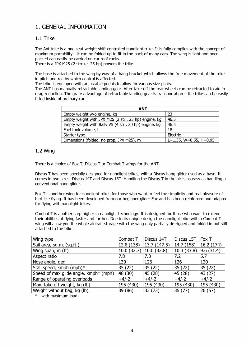
1.1 Trike The Ant trike is a one seat weight shift controlled nanolight trike. It is fully complies with the concept of
maximum portability – it can be folded up to fit in the back of many cars. The wing is light and once packed can easily be carried on car roof racks.
There is a JPX M25 (2 stroke, 25 hp) powers the trike. The base is attached to the wing by way of a hang bracket which allows the free movement of the trike
in pitch and roll by which control is affected. The trike is equipped with adjustable pedals to allow for various size pilots.
The ANT has manually retractable landing gear. After take-off the rear wheels can be retracted to aid in drag reduction. The grate advantage of retractable landing gear is transportation – the trike can be easily
fitted inside of ordinary car.
ANT
Empty weight w/o engine, kg 23
Empty weight with JPX M25 (2 str., 25 hp) engine, kg 46.5
Empty weight with Baily V5 (4 str., 20 hp) engine, kg 46.5
Fuel tank volume, l 18
Starter type Electric
Dimensions (folded, no prop, JPX M25), m L=1.35, W=0.55, H=0.95
1.2 Wing
There is a choice of Fox T, Discus T or Combat T wings for the ANT.
Discus T has been specially designed for nanolight trikes, with a Discus hang glider used as a base. It comes in two sizes: Discus 14T and Discus 15T. Handling the Discus T in the air is as easy as handling a
conventional hang glider.
Fox T is another wing for nanolight trikes for those who want to feel the simplicity and real pleasure of
bird-like flying. It has been developed from our beginner glider Fox and has been reinforced and adapted for flying with nanolight trikes.
Combat T is another step higher in nanolight technology. It is designed for those who want to extend
their abilities of flying faster and farther. Due to its unique design the nanolight trike with a Combat T
wing will allow you the whole aircraft storage with the wing only partially de-rigged and folded in but still attached to the trike.
Wing type Combat T Discus 14T Discus 15T Fox T
Sail area, sq.m. (sq.ft.) 12.8 (138) 13.7 (147.5) 14.7 (158) 16.2 (174)
Wing span, m (ft) 10.0 (32.7) 10.0 (32.8) 10.3 (33.8) 9.6 (31.4)
Aspect ratio 7.8 7.3 7.2 5.7
Nose angle, deg 130 126 126 120
Stall speed, kmph (mph)* 35 (22) 35 (22) 35 (22) 35 (22)
Speed of max glide angle, kmph* (mph) 48 (30) 45 (28) 45 (28) 43 (27)
Range of operating overloads +4/-2 +4/-2 +4/-2 +4/-2
Max. take off weight, kg (lb) 195 (430) 195 (430) 195 (430) 195 (430)
Weight without bag, kg (lb) 39 (86) 33 (73) 35 (77) 26 (57) * - with maximum load

5
1.3 Ultralight
The ANT in combination with any of above mentioned wing has proven to be an excellent combination to feel simplicity and real pleasure of bird-like flying.
The entire aircraft can be de-rigged and stored at home with minimum time and effort without any tools
required.
2. LIMITATIONS 2.1 General The limitations section of this Manual outlines the various operating limitations, instrument function and
placards necessary for the safe operation of the ANT with engine and standard equipment.
2.2 Airspeed Limitations
SPEED km/h mph COMMENTS
Vne (never exceed
speed)
90 56 Do not exceed this speed in any
operation
Va (maximum
maneuvering speed)
70 44 Do not make full or abrupt control
movements above this speed
2.3 Power Plant Limitations 2.3.1 Engine
JPX M25 (2 stroke, 25 hp) with electric starter. The trike can be equipped with other engines with similar characteristics.
WARNING: This is non-certified aircraft engine, the possibility of engine failure exists at all time. Do not operate
this engine over densely populated areas. Do not operate this engine over terrain where a safe, power off landing cannot be performed.
2.3.2 Fuel
The following fuels can be used.
Fuel mixture of premium petrol 95-99 (Ron) Octane unleaded or AVGAS 100LL and oil at 2%. Synthetic top-quality oil for 2-strokes engines.
2.4 Weight limits Maximum take off weight, kg (lb) 195 (430)
Empty weight (with Emergency Rescue System), kg (lb) 87.5 (193)
Permitted range of pilot weight, kg (lb) 55-100 (121-220)
ENGINE PERFORMANCE & LIMITATIONS
Engine speed Take off (Max 5 minutes) 7500-7900 rpm
Maximum (continuous) 6500 rpm
Take off power 25 hp
6
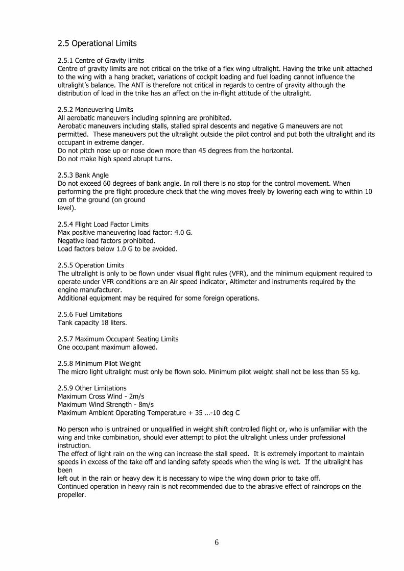
2.5 Operational Limits
2.5.1 Centre of Gravity limits Centre of gravity limits are not critical on the trike of a flex wing ultralight. Having the trike unit attached
to the wing with a hang bracket, variations of cockpit loading and fuel loading cannot influence the
ultralight’s balance. The ANT is therefore not critical in regards to centre of gravity although the distribution of load in the trike has an affect on the in-flight attitude of the ultralight.
2.5.2 Maneuvering Limits
All aerobatic maneuvers including spinning are prohibited. Aerobatic maneuvers including stalls, stalled spiral descents and negative G maneuvers are not
permitted. These maneuvers put the ultralight outside the pilot control and put both the ultralight and its
occupant in extreme danger. Do not pitch nose up or nose down more than 45 degrees from the horizontal.
Do not make high speed abrupt turns.
2.5.3 Bank Angle
Do not exceed 60 degrees of bank angle. In roll there is no stop for the control movement. When performing the pre flight procedure check that the wing moves freely by lowering each wing to within 10
cm of the ground (on ground level).
2.5.4 Flight Load Factor Limits Max positive maneuvering load factor: 4.0 G.
Negative load factors prohibited. Load factors below 1.0 G to be avoided.
2.5.5 Operation Limits
The ultralight is only to be flown under visual flight rules (VFR), and the minimum equipment required to
operate under VFR conditions are an Air speed indicator, Altimeter and instruments required by the engine manufacturer.
Additional equipment may be required for some foreign operations.
2.5.6 Fuel Limitations
Tank capacity 18 liters.
2.5.7 Maximum Occupant Seating Limits One occupant maximum allowed.
2.5.8 Minimum Pilot Weight
The micro light ultralight must only be flown solo. Minimum pilot weight shall not be less than 55 kg.
2.5.9 Other Limitations
Maximum Cross Wind - 2m/s Maximum Wind Strength - 8m/s
Maximum Ambient Operating Temperature + 35 …-10 deg C
No person who is untrained or unqualified in weight shift controlled flight or, who is unfamiliar with the
wing and trike combination, should ever attempt to pilot the ultralight unless under professional instruction.
The effect of light rain on the wing can increase the stall speed. It is extremely important to maintain speeds in excess of the take off and landing safety speeds when the wing is wet. If the ultralight has
been
left out in the rain or heavy dew it is necessary to wipe the wing down prior to take off. Continued operation in heavy rain is not recommended due to the abrasive effect of raindrops on the
propeller.

7
CAUTION MOISTURE ON THE WING CAN INCREASE STALL SPEED AND SHOULD BE REMOVED PRIOR TO TAKE
OFF.
3. ULTRALIGHT & SYSTEMS DESCRIPTION 3.1 General This section provides descriptions of the ultralight and its systems as well as methods of operation where
appropriate. Information on the ultralight flight controls is detailed in this section, but it is mandatory that you receive
professional training prior to any solo flight.
3.2 Ground / Flight Control Ground / flight Controls are as follows: - Push left pedal = Taxi steering right
- Push left toe = Brakes on - Ignition switch forward = Switch on
- Control bar move left = Right turn
- Control bar move right = Left turn
- Control bar push out = Pitch up - Push right toe = Throttle open
3.3. Retractable landing gear The ANT trike is equipped with manually retractable landing gear. After take-off the rear wheels can be retracted to aid in drag reduction. Another advantage of retractable landing gear is transportation – the disassembled trike with landing
gear retracted can be easily fitted in its transportation bag inside of ordinary car.
3.4. Control Panel
The control panel positioned on the left rest arm (Photo 1) and consists of: -tachometer and hour meter,
-key,
-ignition switch, -start button,
-primer.
3.5 Occupant restraint Harness The seat is fitted with a restraint harness system.
Photo 1
3.6 Engine The power unit is a JPX M25 (2 stroke, 25 hp). The engine is fitted with a belt drive, which delivers
smooth thrust via a reduction drive.

8
3.7 Propeller Manufacturer: Helix Type: 2 Blade Composite
Diameter: 1300 mm
The maximum propeller speed occurs when the engine RPM reaches 7900 RPM.
3.8 Brake System A front wheel disk brake system with mechanical drive is used on the ultralight. It is rather effective
especially on the asphalt or concrete runways. It is recommended to brake with caution and do not apply
too much force to the brake pedal. During landing run use the brake in the second part of the run only, pressing on the brake pedal gradually.
CAUTION
THE BRAKE SYSTEM IS RATHER EFFECTIVE ESPECIALLY ON THE ASPHALT AND CONCRETE RUNWAYS. BRAKING AT HIGH SPEED SHARPLY WILL RESULT IN THE BRAKE DISC OVERLOAD AND THE BRAKE
SYSTEM FAIL.
3.9 Emergency Rescue System. The ultralight may be equipped with emergency rescue system. The rescue system provides for landing
in case of emergency without the necessity for the pilot to leave the ultralight in the air.
4. ULTRALIGHT ASSEMBLY PROCEDURES 4.1 Trike Assembly Procedure The trike is easy to de-rig, pack-up and transport in pack-up bags as shown on the photo. It comes in two bags – the trike and the engine, with the propeller, the upper pylon and the front brace (Photo 2, 3).
Photo 2 Photo 3

9
4.1.1 Unzip the bag with the trike (Photo 4, 5).
Photo 4 Photo 5
4.1.2 Extract both landing gear legs (see photo below) and lock them in position with the lock system as
shown on the photo (Photo 6, 7).
Photo 6 Photo 7 4.1.3 Install the front lower beam with the front wheel and fix it with the bolts and butterfly nuts and
secure them with a safety rings as shown on the photo (Photo 8, 9, 10).
Photo 8 Photo 9

10
Photo 10
4.1.4 Open the bag with the engine (Photo 11). Mount the engine on the trike by installing two bolts: upper one and lower one. Tighten butterfly nuts and secure them with safety rings (Photo 12).
Photo 11 Photo 12
4.1.5 Install the throttle rod. It is easier to do after fixing the throttle pedal in its rear position (Photo 13). Feed the throttle rod with the rod end through the rod support and position it in place as shown on the photo (Photo 14).
Photo 13 Photo 14

11
4.1.6 Connect the fuel line with the quick connector (Photo 15) and electric wiring with power connector
(Photo 16).
Photo 15 Photo 16
4.1.7 Mount the control panel by installing the mounting plate in to the corresponding pocket and fixing it with Velcro (Photo 17). Fix the electric wires hose to the side of the seat frame with Velcro straps
(Photo 18).
Photo 17 Photo 18
4.1.8 Install the main upper pylon and fix it with the bolts and butterfly nuts and secure with safety rings as
shown on the photo (Photo 19).
Photo 19

12
4.1.9 Install the front upper brace, attaching it first to the main upper pylon (Photo20) and then to the
front lower beam (Photo 21).
Photo 20 Photo 21
4.1.10 Install the propeller (Photo 22). Tightening torque for the propeller bolts is 22 Nm. Secure all bolts
in pairs with locking wire.
Now your trike is ready for attaching the wing.
Photo 22 4.2 Pedals adjustment The ANT trike has ground adjustable pedals according to the pilot’s size. On the photo 23 pedals are in
fwd position. To move pedals backwards unbolt and remove the front wheel fork and remove the front wheel fairing. In the trike accessories find the rubber insert and install it in the front wheel fearing slot as
shown on the photo (Photo 24). Install the front wheel fork in the rear hole on the lower front brace and
install the front wheel fairing in place, bolt them and tighten the joints.
Photo 23 Photo 24 4.3 Wing Assembly Procedure The wing assembly procedure and all information regarding the wing are written in a wing Manual.
Please read it thoroughly and make sure it is clearly understood.

13
5. PREFLIGHT INSPECTION OF THE WING
Conduct preflight inspection of the wing before attaching it to the trike as written in a wing Manual.
6. ATTACHING A WING TO THE TRIKE
6.1. Check that the ignition switch and the key are in
off position. Position the wing on its control frame, facing into the
wind, with the nose on the ground. Wheel the trike behind the wing (Photo 25), rolling the
front wheel over the control bar. The pylon of the trike
should be held down and the propeller should be positioned horizontal. Remove the rear part of the keel
tube from the wing.
Photo 25 6.2. Lift the nose of the wing up until high enough to connect the universal junction of the trike to the U-
bracket of the wing (Photo 26). Insert the heart bolt, tighten nut firmly and secure with a safety ring. For
Fox-T wing connect the safety loop as shown on the photo (Photo 27). For other wing types simply connect the safety loop over the keel tube.
Photo 26 Photo 27
6.6. Lift nose of the wing to allow the front wheel to
be rolled rearward over the control frame so that the base tube is forward of the cockpit and the rear of the
keel rests on the pylon.
6.7. Install the nose cone of the wing by applying the
top Velcro first then gently tension over the nose plates and attach the Velcro to the undersurface of the
wing (Photo 28).
Photo 28

14
6.8. Attach an auxiliary strap to the pedals as shown on
the photo (Photo 29).
6.9. Go to the nose of the wing. Step on the auxiliary
strap with one foot to prevent the trike from lifting up the front wheel when rising the wing up. With the front
Photo 29 brace tube in one hand and the base tube in the other hand lift the base tube rising the wing up (Photo 30). In
strong winds maintain a firm grip on the base tube.
NOTE Note on the photo 31 the upper bolt of the joint of the vertical pylon removed prior to the wing
attachment, so the upper pylon rotates around the lower bolt in the joint.
Photo 30 Photo 31 6.10. Attach the front brace tube in position using a quick-pin (Photo 32).
Photo 32 Photo 33
6.11. Install the bolt into the pylon’s joint as shown on the picture (Photo 33), tighten it and secure with a safety ring.

15
6.12 Secure the base tube with the safety belt.
Park the ultralight in a crosswind position with
the base tube secured with a safety belt. The wing should be at approx zero angle of attack to
avoid the ultralight to be turned upside down with the wind (Photo 34).
Photo 34
7. FLIGHT PREPARATION
7.1 General Prior each flight depending on the purposes of flight it is necessary to work out the flight task: - prepare flight maps and study the flight conditions;
- study meteorological conditions at the departure airfield, on course and at the arrival airfield; - estimate the possibility of accomplishment the flight task;
- proceed with all necessary formalities which are relative to given flight; - estimate the necessary fuel state;
- conduct complete preflight inspection of the ultralight.
WARNING NO ATTEMPT SHOULD BE MADE TO FLY THE ULTRALIGHT WITHOUT APPROPRIATE ULTRALIGHT FLIGHT TRAINING WITH AN APPROVED INSTRUCTOR.
7.2 Complete Ultralight Pre Flight inspection A full pre-flight inspection should precede every flight you make, not just the first flight of the day. Daily inspections as outlined in the JPX Operator’s Manual should be carried out in conjunction with the follow inspections.
WARNING
ENSURE THAT THE IGNITION SWITCH AND THE KEY ARE OFF PRIOR TO INSPECTION.
7.2.1 Trike Pre-flight Inspection
- No leaks from fuel system and engine.
- Fuel filter clean and operational. - Sufficient fuel for flight.
- No splitting, denting or delaminating of the propeller.
- Propeller hub assembly secure and tie wired. - No cracking in tire treads, or evidence of cracking around the rim. Wheels are secured.
- No bolts bent, fractured or evidence of corrosion. - Electrical system secure and operational.
- Throttle operation, both foot and hand throttle (if available). Verify free and full movement. - Seat belt attachments secure.
- All engine components secure - air filter, muffler, plug leads.
- Mechanical components. Rotate propeller and observe for noise or excessive resistance.
7.2.2 Wing Pre-flight Inspection The complete preflight inspection of the wing is outline in the wing Manual.
16
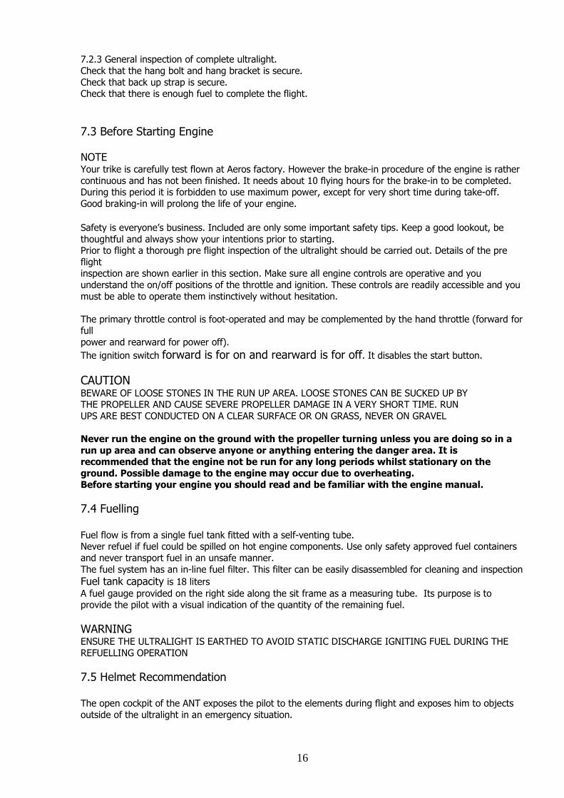
7.2.3 General inspection of complete ultralight.
Check that the hang bolt and hang bracket is secure.
Check that back up strap is secure. Check that there is enough fuel to complete the flight.
7.3 Before Starting Engine NOTE Your trike is carefully test flown at Aeros factory. However the brake-in procedure of the engine is rather
continuous and has not been finished. It needs about 10 flying hours for the brake-in to be completed. During this period it is forbidden to use maximum power, except for very short time during take-off.
Good braking-in will prolong the life of your engine.
Safety is everyone’s business. Included are only some important safety tips. Keep a good lookout, be
thoughtful and always show your intentions prior to starting. Prior to flight a thorough pre flight inspection of the ultralight should be carried out. Details of the pre
flight inspection are shown earlier in this section. Make sure all engine controls are operative and you
understand the on/off positions of the throttle and ignition. These controls are readily accessible and you
must be able to operate them instinctively without hesitation.
The primary throttle control is foot-operated and may be complemented by the hand throttle (forward for full
power and rearward for power off).
The ignition switch forward is for on and rearward is for off. It disables the start button.
CAUTION BEWARE OF LOOSE STONES IN THE RUN UP AREA. LOOSE STONES CAN BE SUCKED UP BY THE PROPELLER AND CAUSE SEVERE PROPELLER DAMAGE IN A VERY SHORT TIME. RUN
UPS ARE BEST CONDUCTED ON A CLEAR SURFACE OR ON GRASS, NEVER ON GRAVEL
Never run the engine on the ground with the propeller turning unless you are doing so in a
run up area and can observe anyone or anything entering the danger area. It is recommended that the engine not be run for any long periods whilst stationary on the
ground. Possible damage to the engine may occur due to overheating. Before starting your engine you should read and be familiar with the engine manual.
7.4 Fuelling Fuel flow is from a single fuel tank fitted with a self-venting tube. Never refuel if fuel could be spilled on hot engine components. Use only safety approved fuel containers
and never transport fuel in an unsafe manner.
The fuel system has an in-line fuel filter. This filter can be easily disassembled for cleaning and inspection
Fuel tank capacity is 18 liters
A fuel gauge provided on the right side along the sit frame as a measuring tube. Its purpose is to provide the pilot with a visual indication of the quantity of the remaining fuel.
WARNING ENSURE THE ULTRALIGHT IS EARTHED TO AVOID STATIC DISCHARGE IGNITING FUEL DURING THE
REFUELLING OPERATION
7.5 Helmet Recommendation The open cockpit of the ANT exposes the pilot to the elements during flight and exposes him to objects
outside of the ultralight in an emergency situation.

17
Helmet and eye protection are recommended to protect the pilot from precipitation, strike by insects.
Helmet is also recommended for risk reduction during an emergency landing of the ultralight. The helmet
recommended for use in the ultralight is that certified for air sports.
8. ULTRALIGHT FLYING
8.1 Starting the engine All controls should be checked with the ignition OFF.
CAUTION REMEMBER TO CLEAR PROP!
The engine should be started with the pilot in the seat.
The follow procedure should be used:
- Brake is in the on position - Hand and foot throttle off
- Turn the key switch on. - Switch ignition ON.
- Press the primer three times (or until the fuel volume is filled) unless the engine is hot.
- Check visually that the propeller area is clear and call “Clear Prop” out loud. - Depress start button. If the engine refuses to start switch off the ignition before investigation.
- When the engine starts, increase the engine RPM to a little above idle. - Warm up the engine.
Keep an ultralight log and enter any unusual engine behavior. Do not fly unless you have corrected a given problem and recorded the correction in the log.
8.2 Taxiing Taxiing in normal conditions is fairly easy.
The control frame should be positioned so that it is in the approximate position for normal trim speed. The pilot’s feet actuate steering on the ground. Left turn occurs when the right footrest is pushed
forward. Right turn occurs when the left footrest is pushed forward.
NOTE Control sense for turning is opposite to that of a conventional three axis ultralight.
When taxiing in strong wind conditions the follow procedures apply: · Head Wind conditions require the nose of the wing to be lowered just below the trim position.
· Down Wind conditions requires the nose of the wing to be raised just above the trim position.
· Cross wind conditions requires the upwind tip to be lowered.
8.3 Before take off Before flight a full-throttle check is to be carried out. During this operation the pilot must be seated in the
cockpit and prepared to switch off the ignition at very short notice if an emergency should arise.
WARNING NEVER LEAVE YOUR ULTRALIGHT UNATTENDED WHILE THE ENGINE IS RUNNING.
CAUTION BEWARE OF LOOSE STONES IN THE RUN UP AREA. LOOSE STONES CAN BE SUCKED UP BY
THE PROPELLER AND CAUSE SEVERE PROPELLER DAMAGE IN A VERY SHORT TIME. RUN UPS ARE BEST CONDUCTED ON A CLEAR SURFACE OR ON GRASS, NEVER ON GRAVEL
18
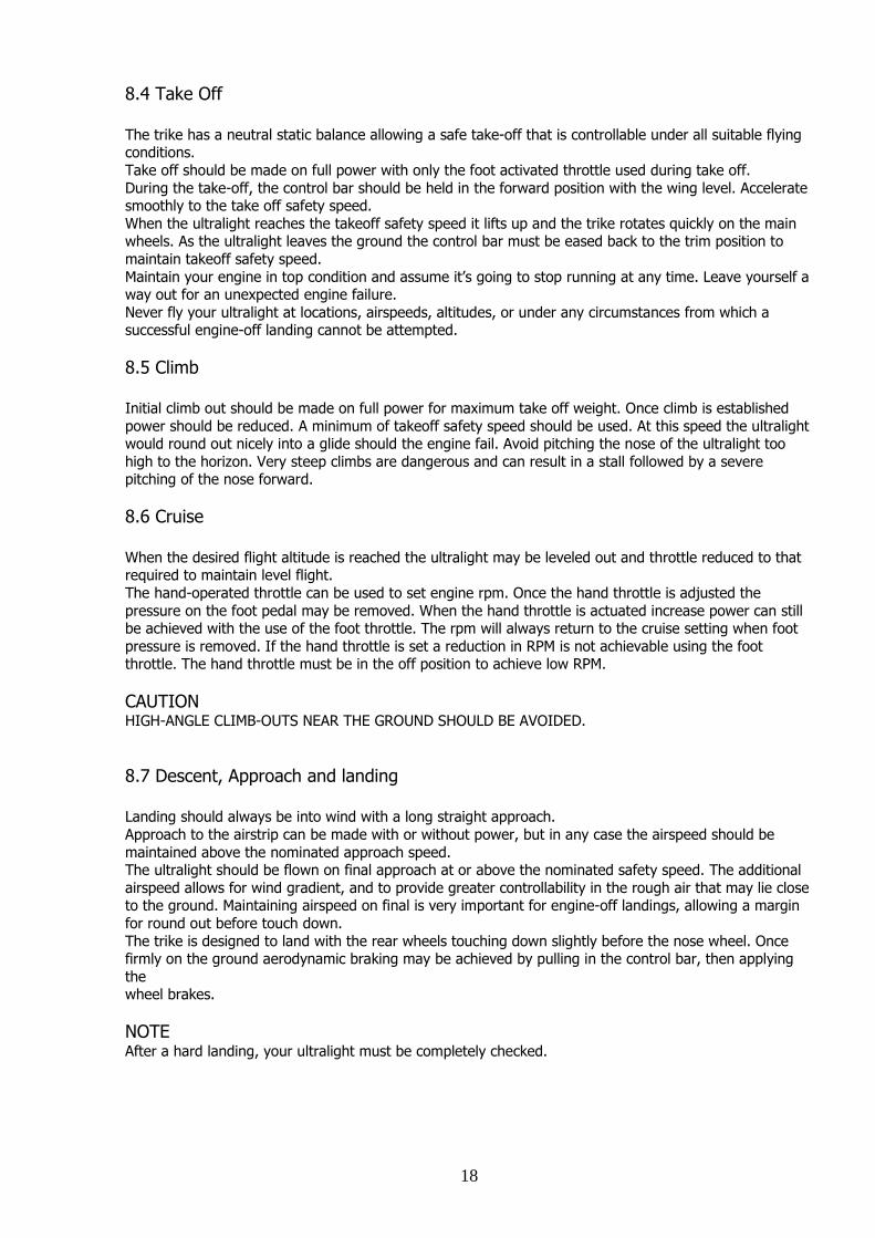
8.4 Take Off The trike has a neutral static balance allowing a safe take-off that is controllable under all suitable flying conditions.
Take off should be made on full power with only the foot activated throttle used during take off.
During the take-off, the control bar should be held in the forward position with the wing level. Accelerate smoothly to the take off safety speed.
When the ultralight reaches the takeoff safety speed it lifts up and the trike rotates quickly on the main wheels. As the ultralight leaves the ground the control bar must be eased back to the trim position to
maintain takeoff safety speed.
Maintain your engine in top condition and assume it’s going to stop running at any time. Leave yourself a way out for an unexpected engine failure.
Never fly your ultralight at locations, airspeeds, altitudes, or under any circumstances from which a successful engine-off landing cannot be attempted.
8.5 Climb Initial climb out should be made on full power for maximum take off weight. Once climb is established
power should be reduced. A minimum of takeoff safety speed should be used. At this speed the ultralight would round out nicely into a glide should the engine fail. Avoid pitching the nose of the ultralight too
high to the horizon. Very steep climbs are dangerous and can result in a stall followed by a severe pitching of the nose forward.
8.6 Cruise When the desired flight altitude is reached the ultralight may be leveled out and throttle reduced to that required to maintain level flight.
The hand-operated throttle can be used to set engine rpm. Once the hand throttle is adjusted the
pressure on the foot pedal may be removed. When the hand throttle is actuated increase power can still be achieved with the use of the foot throttle. The rpm will always return to the cruise setting when foot
pressure is removed. If the hand throttle is set a reduction in RPM is not achievable using the foot throttle. The hand throttle must be in the off position to achieve low RPM.
CAUTION HIGH-ANGLE CLIMB-OUTS NEAR THE GROUND SHOULD BE AVOIDED.
8.7 Descent, Approach and landing Landing should always be into wind with a long straight approach.
Approach to the airstrip can be made with or without power, but in any case the airspeed should be
maintained above the nominated approach speed. The ultralight should be flown on final approach at or above the nominated safety speed. The additional
airspeed allows for wind gradient, and to provide greater controllability in the rough air that may lie close to the ground. Maintaining airspeed on final is very important for engine-off landings, allowing a margin
for round out before touch down.
The trike is designed to land with the rear wheels touching down slightly before the nose wheel. Once firmly on the ground aerodynamic braking may be achieved by pulling in the control bar, then applying
the wheel brakes.
NOTE After a hard landing, your ultralight must be completely checked.

19
8.8 Cross Wind Landing and Take Off Pilots with less experience should avoid landing or taking off with high crosswind components, as skills do not always match the capabilities of the ultralight. Crosswind landing or take off with low wind
components up to 1 m/s are quite safe and controllable, even to the inexperienced pilot.
WARNING NEVER STALL THE ULTRALIGHT WITH THE NOSE PITCHED UP BEYOND 45 DEGREES.
MANOEUVRES BEYOND THIS ARE DANGEROUS AND CAN RESULT IN A TAIL SLIDE FOLLOWED BY A SEVERE TUMBLE. REFER TO SECTION 3.3.12 OF THIS FLIGHT MANUAL FOR DETAILS OF THE
PROCEDURES FOR RECOVERY FROM UNUSUAL ATTITUDES
The nominated approach speed of 51 km/h should be increased to 60 km/h when landing in cross wind conditions of 5m/s or more.
After touchdown in cross wind conditions the relative airflow over the wing will become increasingly span
wise (From tip to tip) as the ultralight slows down. The upwind tip should be lowered slightly (the amount depends on the wind strength), and the undercarriage wheels will retain firm contact with the ground.
Take off procedure is unchanged for the nominated crosswind limit. The upward may need to be lowered at the start of the take off procedure in higher cross winds.
8.9 Go-Around Landing During a situation where a go-around landing is required, normal take off power and procedures should
be used.
8.10 Stopping the Engine To stop the engine after a period of running, the ignition should be switched off at idle. If the engine has
been running under full power, allow the engine to cool at idle before switching off.
8.11 After Landing / Securing After landing and when in the parking switch the ignition off and set the key in off position. The ultralight
should be parked in a crosswind position with the base tube secured to the mast brace. The rescue system safety pin should be inserted before leaving the ultralight.

20
9. LANDING GEAR OPERATION
The ANT trike equipped with manually retractable landing gear. The landing gear retraction and extension is straight forward and easy.
To retract the landing gear on the ground proceed as follows. Lift the rear part of the trike up (ask
someone to help you if necessary), unlock the lock mechanism (Photo 35) and fold the undercarriage one after another forward until it lock in the most forward (retracted) position (Photo 36).
Photo 35 Photo 36 With the landing gear retracted the trike when disassembled in its transportation bag can be easily fitted
inside of ordinary car.
For the landing gear extension pull the landing gear handle (Photo 37) to unlock the landing gear.
Photo 37 Photo 38 Extend the landing gear one after another and fix them in the extended position with the lock mechanism
(Photo 38).
The in-flight landing gear retraction and extension procedures are similar to those described above. The
only difference is that the pilot will be sitting in the seat and piloting the trike which makes it less comfortable to operate the undercarriage.
WARNING
PRIOR ATTEMPTING TO RETRACT THE LANDING GEAR IN FLIGHT, TRAIN DOING THIS ON THE GROUND FROM THE PILOT SEAT. SECURE THE TRIKE IN LIFTED POSITION BEFORE TRAINING.
WARNING DON’T FORGET TO EXTEND THE LANDING GEAR BEFORE LANDING.

21
10. EMERGENCY PROCEDURES
10.1 General This section contains operating procedures for flight and system emergency conditions that are essential
for the continued safe operation of the ultralight. Always maintain correct airspeed and altitudes in the circuit area.
Never fly in uncertain weather conditions and always fly within your proven ability. Be sure only to extend
your capabilities under planned training situations. Carry out safe airmanship whilst flying and be aware of possible emergency landing areas along your
flight path. If possible check these areas from the ground as you enter the airfield or flying site. This technique is for safety reasons as engines are susceptible to stopping, no matter how reliably
manufactured or maintained. Keep a good lookout for other ultralight, always be thoughtful and show your intentions.
Remember that the manufacturer cannot foresee all conceivable circumstances. Particular circumstances
such as multiple or unanticipated emergencies, adverse weather etc may require modification to these procedures. A thorough knowledge of the ultralight and its systems is required to analyze the situation
correctly and to determine the best course of action.
Maximum maneuvering speed is 65 km/h.
Best glide speed (with maximum load) is 50 km/h.
10.2 Engine Failure on Take Off 10.2.1 Engine Failure on Take Off Run
If the engine fails on take off run before the ultralight has lifted off proceed as follows: - pull the control bar in to prevent the ultralight lifting from the ground;
- use pedals to maintain the ground run direction, using the brake at the same time, avoid direct
collision with obstacles; - switch off the ignition.
10.2.2 Engine Failure on Climb Out
If your engine fails on climb out before you have reached 5 meters altitude, land straight ahead. Proceed
as follows: - pull the control bar in further than the trim position to prevent the ultralight from loosing
airspeed; - Land in accordance with section 6.7 of the Manual. Avoid direct collision with obstacles.
- switch the ignition off.
10.3 Engine Failure at Height If the engine stops while operating at cruise or full power when the ultralight is well clear of the ground, check fuel contents and make sure that ignition is on.
If your engine fails in flight, do not attempt to restart the engine unless one of these items is found to be incorrect and is able to be rectified. Relax and maintain control whilst concentrating on correct forced
landing techniques.
10.4 Full Power Engine Shutdown (In Flight) If the throttle should jam full open in flight proceed as follows:
Maintain Control. Get height with engine at full power, adjust height and ground position to improve the outcome of
forced landing.
Increase airspeed to keep the climb angle less than 30 degrees above the horizontal. Switch off ignition.
Prepare for forced landing section 9.5.

22
10.5 Forced Landing Proceed as follows: Maintain control and airspeed - nominated approach speed.
Close the throttle.
Switch the ignition off. Tighten the seat belts.
Carry out final approach and landing as closely as possible to normal power off landing procedure.
10.6 In Air Engine Fire For fire occurring whilst in flight, the initial procedure would be to maintain control of the ultralight and
evaluate the extent of the fire. This emergency is unlikely to occur but to avoid any further problems, use
common sense and land the ultralight safely. Proceed as follows: Maintain Control
Ignition off Forced Landing
After landing release seat belt
Evacuate ultralight.
10.7 On Ground Engine Fire If fire occurring whilst on the ground proceed as follows:
Maintain control and use remaining speed to clear people, others ultralights and buildings. Close the throttle.
Turn the ignition off.
After stopping release seat belt. Evacuate the ultralight.
10.8 Propeller Damage The indication of propeller damage is usually felt by extreme vibration and lack of thrust. Proceed as follows:
Maintain Control and airspeed.
Close the throttle. Turn the ignition off.
Prepare for forced landing. This problem may be avoided if precautions are taken prior to take off. Inspect the airstrip or ground you
are going to use as your take off area for sticks, rocks or any debris that may be flicked up by the tires and sucked
through the propeller.
Ensure that all items carried on board (such as cameras and sunglasses) are secured so they are not able to come loose and pass through the propeller.
10.9 Sail Damage If you encounter damage to the sailcloth during flight, the first procedure is to maintain control of the ultralight. If the sail damage is not changing the flight characteristics of the ultralight, land at the nearest
landing field to inspect the damage.
10.10 Emergency Rescue System The Emergency rescue system is only to be used in emergency situations as a last resort and when you are certain
that: · the ultralight has suffered structural damage to the extent that control is not possible; or
· if the ultralight is in an irrecoverable situation where structural damage is likely to occur.

23
To operate the parachute pull the handle at least twenty centimetres for the parachute rocket projectile
to be activated. The parachute will allow the complete ultralight to be lowered to the ground.
WARNING AT FULL ENGINE RPM THE TIP OF THE PROPELLER IS SPINNING AT SPEEDS IN EXCESS OF 650
KILOMETRES PER HOUR. EVEN SMALL OBJECTS CAN CAUSE SIGNIFICANT DAMAGE TO THE PROPELLER.
WARNING IT IS IMPORTANT TO REALISE THAT WHILST THE PARACHUTE CONTROLS THE RATE OF DESCENT, THE
PILOT WILL HAVE NO CONTROL OVER THE PLACE THE ULTRALIGHT WILL LAND.
For using emergency rescue system proceed as follows:
Close the throttle. Turn the ignition off.
Tighten seat belt. Check that emergency rescue system pin is removed.
Deploy emergency parachute
Prepare for the forced landing.
10.11 Stalls In practice, in level flight it is difficult to induce a nose down stall of the ultralight, although it greatly
depends on the wing type you fly. The beginning of stall is indicated by a significant increase in control bar loads.
Recovery from a mild stall is very gentle, whether power is on or off. Recovery is quick, with height loss of less than 20 meters. A stall would have to be forced violently, to induce a danger.
Never stall with the nose pitched up too high. This is a dangerous maneuver and can result in a tail slide
followed by a severe tumble.
10.12 Spins and Spiral Descents Deliberate spinning is prohibited. A spiral dive may develop after a stall if the bar is maintained at the forward limit and a large roll rate is
allowed to develop. If this condition is not corrected it will lead to large and increasing roll attitudes (beyond the 60 degree limit). Increasing attitude, increasing speeds and large control bar feed back
forces will occur. Incipient spiral dives can be terminated at any time by rolling wing level.
WARNING DO NOT ATTEMPT TO SPIN THE ULTRALIGHT. SPIRAL DIVES SHOULD NOT BE ATTEMPTED.
DURING DESCENDING TURNS ULTRALIGHT ATTITUDE MUST BE KEPT WITHIN PLACARDED PITCH,
ROLL AND AIRSPEED LIMITS.
11. ULTRALIGHT DE-RIGGING PROCEDURE
Careful attention to the recommended rigging and de-rigging sequences will protect the ultralight from the
risk of unnecessary damage. The de-rigging procedure is a direct reversal of the rigging procedure.
11.1 Removing the wing from the Trike See section 6 (Attaching the wing to the Trike) and use reverse procedure:

24
- Remove the upper bolt from the pylon joint.
· Remove the quick-pin from the front support tube.
· Lower the wing until the control bar is on the ground. - Remove the nose cone from the wing.
- Lower the nose of the wing to allow the front wheel to be rolled forward over the control bar. - Detach the back up loop.
· Unbolt the trike from the U Bracket of the wing.
11.2 Wing Break Down Procedure See the appropriate wing Manual for the detailed procedure.
11.3 Trike Disassembling Procedure. The trike disassembling procedure is simply reverse to the trike assembling procedure (See section 4.1 Trike Assembly Procedure).
12. HANDLING SERVICE AND MAINTENANCE
12.1 Introduction This section contains factory recommended procedures for proper ground handling and routine care for Your ANT trike. Included in this section is relevant information required by the operator.
WARNING
IT IS THE PILOTS RESPONSIBILITY TO ENSURE THAT ALL AIRWORTHINESS DIRECTIVES
HAVE BEEN ADDRESSED. IT IS ALSO THE PILOTS RESPONSIBILITY TO ENSURE SERVICING AND MAINTENANCE HAS BEEN PERFORMED.
12.2 Identification Plate
The trike identification plate can be found on the main pylon right side (Photo 39). The Serial
number should be quoted when corresponding
with the factory. For the wing identification plate please refer to
the wing Manual.
Photo 39
12.3 Fuel Sampling There is no drain cock on the fuel tank. To draining fuel from the fuel tank proceed as follow. Open the
filler neck. Lift the front wheel of the trike up until the fuel drain out from the filler neck. It is especially important to remove any water that may have been introduced from the system.

25
The fuel is checked for water and contaminants by draining a sample of the fuel into a clear glass
container. Once a sample has been taken the quality of the fuel can be checked by looking for any water
at the bottom of the glass, and checking for any other visual contaminants. Ensure that there are no ignition sources and that the fuel is disposed of correctly.
If the fuel has been sitting for an extended period without use it may be advisable to replace it with fresh fuel.
12.4 Lubricating Oil Engine lubrication
Mixture lubrication: Super two stroke oil ASTM/CEC standards, API-T classification (e.g. Castrol TTS) mixing ratio 1:50 (2 %).
12.5 Tire Inflation The recommended tire inflation pressures are 2 Bar for both the front and rear tires. When checking the tire pressures the opportunity should be taken to examine the tires for wear, cuts, bruises and other
defects.
12.6 CORS-AIR M 25 Y Engine Maintenance
Every 20 hours: Check the condition and gap (0.7 mm) of the spark plug
Clean the air-filter, the carburettor filter placed at the end of the fuel pipe and the filter of the fuel tank Check the torque of every bolt
Tighten head nuts (in cross order) with a Torque Wrench at 2.2 Kg.m (22Nm) Check the tension and condition of the reduction belt
Check fuel lines
Check the wiring Check that the cord of the starter has no abrasions
Grease the link-sphere between the manifold and the exhaust pipe with lubricating copper-grease suitable for high temperature (up to 1100°). If you can’t find it on the market , please ask to your dealer.
- Every 50 hours Same controls of the 20 hours and furthermore:
Check the torque of the engine’s crankcase nuts Change spark plugs
Change the petals of the reed valve Check the reduction belt and the play of the pulley and change them in case of need
Check the conditions of the starter gears (version with electric start)
Once a year (independently from flight hours) change the diaphragm of the carburettor.
Refer to the CORS-AIR M 25 Y Manual for more information.
13. TRANSPORTATION AND STORAGE With good care and correct maintenance your trike will retain its good conditions for many years.
We recommend that you do not expose your trike to any more direct sunlight than necessary. Do not leave under the sun for long periods of time when you are not flying.
Do not leave your wing on the trike for a long period of time in strong winds. It will decrease the life of
the sail, the hang joint and the frame of your trike. The trike and the engine may be transported in their bags in any vehicle that offers protection from
mechanical damage, soiling and long exposure to rain. It is not recommended that the engine be carried or transported without its bag. During transportation, or when stored on supports, the wing must be supported at its center and at two points not more than one meter from each end.
Supports should be softly padded, and any support systems used for transport, such as roof racks, must

26
use attachment straps that are sufficiently secure to eliminate the possibility of damage from vibration
and movement. Flat straps should be used for tie downs to avoid damage to leading edge Mylar.
Store the trike in a dry room off the ground; air the trike out regularly to avoid mildew, and never store wet.
If you fly at the costal area or your ultralight has been exposed to salt water dismount it and rinse with tap water thoroughly before storage. If you fly frequently at the costal area it is necessary to wash the
ultralight with tap water at least once a month to prevent all aluminum parts from corrosion.
The recommended storage temperature is from –10 to +25 deg. Centigrade.