overview of technical specifications product...
TRANSCRIPT
Page 1 of 14
Safety Interface Solutions Philosophy
Intelliface Flexi Controllers – UE410 Flexi
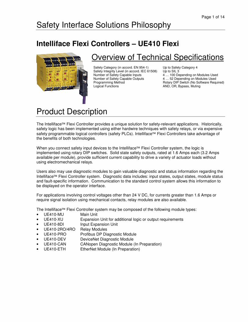
Overview of Technical SpecificationsSafety Category (in accord. EN 954-1) Up to Safety Category 4Safety Integrity Level (in accord. IEC 61508) Up to SIL 3Number of Safety Capable Inputs 4 … 100 Depending on Modules UsedNumber of Safety Capable Outputs 4 … 52 Depending on Modules UsedProgramming Method Rotary DIP Switch (No Software Required)Logical Functions AND, OR, Bypass, Muting
Product DescriptionThe Intelliface Flexi Controller provides a unique solution for safety-relevant applications. Historically,safety logic has been implemented using either hardwire techniques with safety relays, or via expensivesafety programmable logical controllers (safety PLCs). Intelliface Flexi Controllers take advantage ofthe benefits of both technologies.
When you connect safety input devices to the Intelliface Flexi Controller system, the logic isimplemented using rotary DIP switches. Solid state safety outputs, rated at 1.6 Amps each (3.2 Ampsavailable per module), provide sufficient current capability to drive a variety of actuator loads withoutusing electromechanical relays.
Users also may use diagnostic modules to gain valuable diagnostic and status information regarding theIntelliface Flexi Controller system. Diagnostic data includes: input states, output states, module statusand fault-specific information. Communication to the standard control system allows this information tobe displayed on the operator interface.
For applications involving control voltages other than 24 V DC, for currents greater than 1.6 Amps orrequire signal isolation using mechanical contacts, relay modules are also available.
The Intelliface Flexi Controller system may be composed of the following module types:• UE410-MU Main Unit• UE410-XU Expansion Unit for additional logic or output requirements• UE410-8DI Input Expansion Unit• UE410-2RO/4RO Relay Modules• UE410-PRO Profibus DP Diagnostic Module• UE410-DEV DeviceNet Diagnostic Module• UE410-CAN CANopen Diagnostic Module (In Preparation)• UE410-ETH EtherNet Module (In Preparation)

Page 2 of 14
In-system Added ValueThe Intelliface Flexi Controller system consists of a main unit (UE410-MU) and, as required, additionalextension units (UE410-XU, UE410-8DI) followed by one diagnostic module (UE410-DEV, UE410-PRO,UE410-CAN, UE410-ETH). Further, relay modules (UE410-2RO, UE410-4RO) can also be added to thesystem.
Logic is implemented with rotary DIP switches on the front of each module. Logical combinations withmultiple modules are easily set based on how the modules are combined.
A visualization tool has been developed to help simplify module selection and to understand the logicconfiguration possibilities associated with the Intelliface Flexi Controller system. This visualization toolis known as Flexi Configuration Planner and is available at www.ue410flexi.com
Flexi Configuration Planner is an ingenius tool that provides a means for selecting modules, connectingsafety relevant devices and displaying the logic associated with the rotary DIP switch settings. It isimportant to note that this software is not required to configure the logic in the Intelliface FlexiController system, but rather to help understand how the rotary DIP switch settings affect the logic. Anymodification to switch settings after the “teach” process is completed will generate a fault condition.

Page 3 of 14
Ordering InformationMain Unit (UE410-MU)
Number of Inputs Number of SafetyCapable Outputs
Delay Time(Adjustable)
ConnectionType
ModelDesignation
PartNumber
0 s … 5 s UE410-MU3T5 60261360 s … 50 s UE410-MU3T50 6026137
0 s … 300 s
Pluggable screwterminals
UE410-MU3T300 6026138
0 s … 5 s UE410-MU4T5 60326690 s … 50 s UE410-MU4T50 6032670
2 Dual-Channel resp.4 Single-Channel
2 Dual-channel resp.4 Single-channel
0 s … 300 s
Dual levelpluggable springclamp terminals UE410-MU4T300 6032671
Expansion Unit (UE410-XU)Number of Inputs Number of Safety
Capable OutputsDelay Time(Adjustable)
ConnectionType
ModelDesignation
PartNumber
0 s … 5 s UE410-XU3T5 60324700 s … 50 s UE410-XU3T50 6032471
0 s … 300 s
Pluggable screwterminals
UE410-XU3T300 60324720 s … 5 s UE410-XU4T5 6032672
0 s … 50 s UE410-XU4T50 6032673
2 Dual-Channel resp.4 Single-Channel
2 Dual-channel resp.4 Single-channel
0 s … 300 s
Dual levelpluggable springclamp terminals UE410-XU4T300 6032674
Input Expansion Unit (UE410-8DI)Number of SafetyCapable Inputs
Number of SafetyCapable Outputs Connection Type Model
DesignationPart
Number
Pluggable screw terminals UE410-8DI3 60261394 Dual-Channel resp.8 Single-Channel None
Dual level pluggable springclamp terminals UE410-8DI4 6032675
Relay Modules (UE410-2RO/4RO)Number of Normally
Open Contacts 1Number of Normally
Closed Contacts(Diagnostic Output)
Connection Type ModelDesignation
PartNumber
Pluggable screw terminals UE410-2RO3 60261442 x 1 Channel
(2 Channels Total) 1Dual level pluggable spring
clamp terminals UE410-2RO4 6032677
Pluggable screw terminals UE410-4RO3 60261432 x 2 Channel
(4 Channels Total) 2 Dual level pluggable springclamp terminals UE410-4RO4 6032676
Diagnostic Modules (UE410-PRO/DEV/CAN/ETH)
Field bus Protocol ConnectionType
ModelDesignation
PartNumber
PROFIBUS-DP UE410-PRO3 6028407
DeviceNet UE410-DEV3 6032469
CANopen UE410-CAN3 6033111
Ethernet
Pluggable screwterminals
UE410-ETHx3 In Preparation
PROFIBUS-DP UE410-PRO4 6032678
DeviceNet UE410-DEV4 6032679
CANopen UE410-CAN4 6033112
Ethernet
Dual levelpluggable springclamp terminals
UE410-ETHx4 In Preparation
1 See wiring diagram on page 9 for additional information.
Page 4 of 14
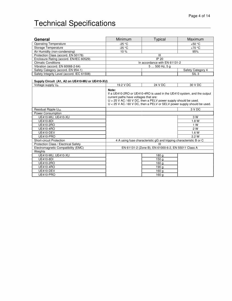
Technical Specifications
General Minimum Typical MaximumOperating Temperature -25 °C +50 °CStorage Temperature -25 °C +70 °CAir Humidity (non-condensing) 10 % 95%Protection Class (accord. EN 50178) IIIEnclosure Rating (accord. EN/IEC 60529) IP 20Climatic Conditions In accordance with EN 61131-2Vibration (accord. EN 60068-2-64) 5 … 500 Hz, 5 gSafety Category (accord. EN 954-1) Safety Category 4Safety Integrity Level (accord. IEC 61508) SIL 3
Supply Circuit (A1, A2 on UE410-MU or UE410-XU)Voltage supply UB 19.2 V DC 24 V DC 30 V DC
Note:If a UE410-2RO or UE410-4RO is used in the UE410 system, and the outputcurrent paths have voltages that are:U > 25 V AC / 60 V DC, then a PELV power supply should be used.U < 25 V AC / 60 V DC, then a PELV or SELV power supply should be used.
Residual Ripple USS 3 V DCPower Consumption UE410-MU, UE410-XU 3 W UE410-8DI 1.8 W UE410-2RO 1 W UE410-4RO 2 W UE410-DEV 1.6 W UE410-PRO 2.2 WShort-circuit Protection 4 A using fuse characteristic gG and tripping characteristic B or CProtection Class / Electrical Safety IIIElectromagnetic Compatibility (EMC) EN 61131-2 (Zone B), EN 61000-6-2, EN 55011 Class AWeights UE410-MU, UE410-XU 180 g UE410-8DI 150 g UE410-2RO 160 g UE410-4RO 190 g UE410-DEV 160 g UE410-PRO 160 g

Page 5 of 14
UE410-MU and UE410-XU Technical SpecificationsGeneral Data Minimum Typical MaximumMaximum Switch-on Time 10 s
Input Circuits (I1-I4, EN, S1-S3)Number of Safety Capable Inputs (I1-I4) 2 Dual-channel resp.
4 Single-channelNumber of Control Inputs (EN, S1-S3) 4Input Voltage HIGH 15 V DC 24 V DC 30 V DCInput Voltage LOW - 5 V DC 0 V DC 5 V DCInput Current HIGH 2.3 mA 3 mA 3.6 mAInput Current LOW - 2.5 mA 0 mA 0.15 mAMinimum Switch ON Time of Signal 70 msMaximum LOW signal at Input Without SwitchingSafety Capable Outputs Q1-Q4. 1 ms
Minimum Switch OFF Time of Signal See Response TimeTeach-in Time of ENTER Button on UE410-MU atPower-up 3 s
Test / Signal Outputs (Control Outputs) (X1-X2)Number of Test / Signal Outputs (X1, X2) 2Output Type PNP Semiconductor, Short-circuit Protected, Cross-Circuit MonitoredOutput Voltage 18 V DC 24 V DC 30 V DCOutput Current 150 mATest Pulse Width Programs 1, 2, 4, 5, 6 12 ms
Program 3.2 52 ms at X1,12 ms at X2
Test Pulse Frequency 5 HzLoad Capacitance 1000 nFLoad Resistance 100 Ω
Safety Capable Output Circuits (Q1-Q4)Number of Safety Capable Outputs 4Output Type PNP Semiconductor, Short-circuit Protected, Cross-Circuit MonitoredOutput Voltage 18 V DC 24 V DC 30 V DCOutput Current per Channel 1.6 AOutput Current per Module 3.2 ATest Pulse Width 300 µsTest Pulse Frequency 5 HzLoad Capacitance 500 nFCable Length (single conductor, ∅ 1.5mm2 ) 100 mAdjustable Delay Settings UE410-MU..T5 or UE410-XU..T5 0 / 0.5 / 1 / 1.5 / 2 / 2.5 / 3 / 3.5 / 4 / 5 s UE410-MU..T50 or UE410-XU..T50 0 / 5 / 10 / 15 / 20 / 25 / 30 / 35 / 40 / 50 s UE410-MU..T300 or UE410-XU..T300 0 / 0.5 / 1 / 1.5 / 2 / 2.5 / 3 / 3.5 / 4 / 5 min

Page 6 of 14
UE410-MU / UE410-XU Program Configuration and Response Time InformationInput Description
Inputs I1/I2 – Dual-channel Equivalent Device with Test Outputs X1, X2Inputs I3/I4 – Dual-channel Equivalent Device with External Test Pulses
Response Time Q1/Q2 Response Time Q3/Q4Program 1 – OR Logic(e.g. Contact Mat OR OSSD) I1/I2 with Contact Mat – 130 ms
I1/I2 with Other Devices – 29 msI3/I4 – 13 ms
Same as Q1/Q2 plus theAdjustable Delay Time Setting
Input DescriptionInputs I1/I2 – Dual-channel Complementary Device with Test Outputs X1, X2 Synchronization Monitoring of 800ms (e.g. RE300 Non-contact Sensor)Inputs I3/I4 – Dual-channel Equivalent Device with External Test Pulses
Response Time Q1/Q2 Response Time Q3/Q4Program 2 – OR Logic(e.g. RE300 OR OSSD)
I1/I2 – 29 msI3/I4 – 13 ms
Same as Q1/Q2 plus theAdjustable Delay Time Setting
Input DescriptionInputs I1/I2 – Dual-channel Equivalent Device with External Test PulsesInputs I3/I4 – Two Single-channel Muting Sensors Time Between Muting Condition & Valid Muting State is 61 ms. Typical Switch OFF Time at Muting Sensors 61 ms. Maximum Switch OFF Time at Muting Sensors 165 ms. Muting Gap Suppression of Inputs I3 / I4 allowed for up to 100ms.
Response Time Q1/Q2/Q3 Response Time Q4
Program 3.1 – Simple Muting(e.g. C4000 Muted with Optical Sensors)
13 ms Same as Q1/Q2/Q3 plus theAdjustable Delay Time Setting
Input DescriptionInputs I1/I2 – IN4000 Inductive Proximity Sensor (I1-X1) or Type 2 Testable Sensor (I2-X2)Inputs I3/I4 – Two Single-channel Muting Sensors Time Between Muting Condition & Valid Muting State is 61 ms. Typical Switch OFF Time at Muting Sensors 61 ms. Maximum Switch OFF Time at Muting Sensors 165 ms. Muting Gap Suppression of Inputs I3 / I4 allowed for up to 100ms.
Response Time Q1/Q2/Q3 Response Time Q4
Program 3.2 – Simple Muting(e.g. IN4000 Muted with Optical Sensors)
I1-X1 to Q1/Q2 – 79 msI2-X2 to Q1/Q2 – 29 ms
Same as Q1/Q2/Q3 plus theAdjustable Delay Time Setting
Input DescriptionInputs I1/I2/I3/I4 – Type IIIC Two Hand Control (Two Dual Channel Complementary Inputs) Synchronization Monitoring of 500 ms
Response Time Q1/Q2 Response Time Q3/Q4Program 4 – Two Hand Control (Type IIIC)
29 ms 29 msInput Description
Inputs I1/I2 – Dual-channel Equivalent Device with Test Outputs X1, X2Inputs I3/I4 – Two Single-channel N.O. Contacts with Test Outputs X1, X2 (Type IIIA THC)
Response Time Q1/Q2 Response Time Q3/Q4Program 5 – AND Logic(e.g. Safety Interlock AND Type IIIA THC)
29 ms 29 msInput Description
Inputs I1/I2 – Dual-channel Equivalent Device with Test Outputs X1, X2Inputs I3/I4 – Dual-channel Equivalent Device with Test Outputs X1, X2
Response Time Q1/Q2/Q3 Response Time Q4Program 6 – AND Logic(e.g. Safety Interlock AND E-Stop)
29 ms Same as Q1/Q2/Q3 plus theAdjustable Delay Time Setting
Input DescriptionInputs I1/I2 – Dual-channel Equivalent Device with External Test PulsesInputs I3/I4 – Dual-channel Equivalent Device with External Test Pulses
Response Time Q1/Q2/Q3 Response Time Q4Program 7 – AND Logic(e.g. C4000 AND S3000)
13 ms Same as Q1/Q2/Q3 plus theAdjustable Delay Time Setting
Input DescriptionInputs I1/I2 – Dual-channel Equivalent Device with External Test PulsesInputs I3/I4 – Dual-channel Equivalent Device with External Test Pulses
Response Time Q1/Q2/Q3 Response Time Q4Program 8 – Independent Outputs(e.g. C4000 Independent of S3000)
13 ms Same as Q3 plus theAdjustable Delay Time Setting
Note: When cascading systems together utilizing the EN (Enable) Input, an additional Response Time of 13 ms must be added to the overall system response time for each cascaded system implemented into the safety chain.
Page 7 of 14
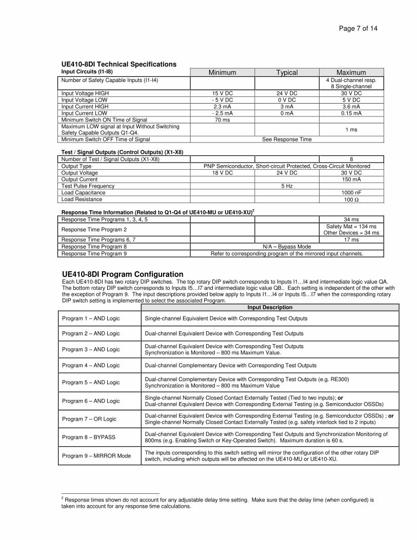
UE410-8DI Technical SpecificationsInput Circuits (I1-I8) Minimum Typical MaximumNumber of Safety Capable Inputs (I1-I4) 4 Dual-channel resp.
8 Single-channelInput Voltage HIGH 15 V DC 24 V DC 30 V DCInput Voltage LOW - 5 V DC 0 V DC 5 V DCInput Current HIGH 2.3 mA 3 mA 3.6 mAInput Current LOW - 2.5 mA 0 mA 0.15 mAMinimum Switch ON Time of Signal 70 msMaximum LOW signal at Input Without SwitchingSafety Capable Outputs Q1-Q4. 1 ms
Minimum Switch OFF Time of Signal See Response Time
Test / Signal Outputs (Control Outputs) (X1-X8)Number of Test / Signal Outputs (X1-X8) 8Output Type PNP Semiconductor, Short-circuit Protected, Cross-Circuit MonitoredOutput Voltage 18 V DC 24 V DC 30 V DCOutput Current 150 mATest Pulse Frequency 5 HzLoad Capacitance 1000 nFLoad Resistance 100 Ω
Response Time Information (Related to Q1-Q4 of UE410-MU or UE410-XU)2
Response Time Programs 1, 3, 4, 5 34 ms
Response Time Program 2 Safety Mat = 134 msOther Devices = 34 ms
Response Time Programs 6, 7 17 msResponse Time Program 8 N/A – Bypass ModeResponse Time Program 9 Refer to corresponding program of the mirrored input channels.
UE410-8DI Program ConfigurationEach UE410-8DI has two rotary DIP switches. The top rotary DIP switch corresponds to Inputs I1…I4 and intermediate logic value QA.The bottom rotary DIP switch corresponds to Inputs I5…I7 and intermediate logic value QB.. Each setting is independent of the other withthe exception of Program 9. The input descriptions provided below apply to Inputs I1…I4 or Inputs I5…I7 when the corresponding rotaryDIP switch setting is implemented to select the associated Program.
Input Description
Program 1 – AND Logic Single-channel Equivalent Device with Corresponding Test Outputs
Program 2 – AND Logic Dual-channel Equivalent Device with Corresponding Test Outputs
Program 3 – AND Logic Dual-channel Equivalent Device with Corresponding Test OutputsSynchronization is Monitored – 800 ms Maximum Value.
Program 4 – AND Logic Dual-channel Complementary Device with Corresponding Test Outputs
Program 5 – AND Logic Dual-channel Complementary Device with Corresponding Test Outputs (e.g. RE300)Synchronization is Monitored – 800 ms Maximum Value
Program 6 – AND Logic Single-channel Normally Closed Contact Externally Tested (Tied to two inputs); orDual-channel Equivalent Device with Corresponding External Testing (e.g. Semiconductor OSSDs)
Program 7 – OR Logic Dual-channel Equivalent Device with Corresponding External Testing (e.g. Semiconductor OSSDs) ; orSingle-channel Normally Closed Contact Externally Tested (e.g. safety interlock tied to 2 inputs)
Program 8 – BYPASS Dual-channel Equivalent Device with Corresponding Test Outputs and Synchronization Monitoring of800ms (e.g. Enabling Switch or Key-Operated Switch). Maximum duration is 60 s.
Program 9 – MIRROR Mode The inputs corresponding to this switch setting will mirror the configuration of the other rotary DIPswitch, including which outputs will be affected on the UE410-MU or UE410-XU.
2 Response times shown do not account for any adjustable delay time setting. Make sure that the delay time (when configured) istaken into account for any response time calculations.

Page 8 of 14
UE410-2RO / UE410-4RO Technical SpecificationsMinimum Typical Maximum
GeneralElectrical Isolation Supply Circuit to Input Circuit No Supply Circuit to Output Circuit Yes Input Circuit to Output Circuit YesElectrical Safety EN 50178 Impulse Voltage Withstand Level (Uimp) 4 kV Overvoltage Category III Pollution Degree 2 Inside, 3 Outside
Output Circuits (13-14, 23-24, 33-34, 43-44)Output Type Positively Guided, Floating Normally Open ContactsNumber of Normally Open (NO) Contacts UE410-2RO (2 x 1 Channel) 2 UE410-4RO (2 x 2 Channel) 4Number of Normally Closed (NC) Contacts UE410-2RO 1 UE410-4RO 2Switching Voltage AC 5 V AC 250 V AC 275 V ACSwitching Voltage DC 5 V DC 230 V DC 275 V DCSwitching Current per Output Channel 10 mA 6 ASwitching Current per Module 12 AOutput Circuit Fusing 6 A using fuse characteristic gG
Utilization CategoryAC-15: Ue 250 V, Ie 3ADC-13: Ue 24 V, Ie 3A
Response Time(UE410-MU / UE410-XU Input to Relay Output)
Response Time of Associated Q1…Q4 Outputof UE410-MU or UE410-XU plus 30 ms
Monitoring Output Circuit (Y14, Y24)Output Type Positively Guided, Non-isolated Normally Open Contact, Current LimitedNumber of Normally Open (NO) Contacts UE410-2RO 1 UE410-4RO 2Switching Voltage DC 18 V DC 24 V DC 30 V DCSwitching Current per Output Channel 75 mALoad Capacitance 200 nF
UE410-DEV / UE410-PRO Technical SpecificationsMinimum Typical Maximum
Output Circuits (X1-X4)Type of Output PNP Semiconductor, Short-circuit ProtectedNumber of Outputs 4Output Voltage 18 V DC 24 V DC 30 V DCOutput Current 100 mALoad Capacitance 100 nFCable Length (single conductor, ∅ 1.5mm2 ) 50 m
Interface - DeviceNetFieldbus DeviceNet (Group 2 Only Server)Interface Level ISO-DIS 11898Connection Technology Open Style Connector, 5-pinSlave Address 0 … 63Baud Rate 125 Kbit/s, 250 Kbit/s, 500 Kbit/s
Interface – PROFIBUS-DPFieldbus PROFIBUS DP V0Interface Level RS-485Connection Technology D-Sub Socket, 9-pinSlave Address 0 … 99Baud Rate Autodetect to 12 Mbit/s
Page 9 of 14
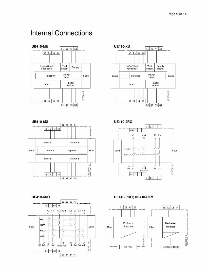
Internal Connections
UE410-MU UE410-XU
UE410-8DI UE410-2RO
UE410-4RO UE410-PRO; UE410-DEV
Page 10 of 14
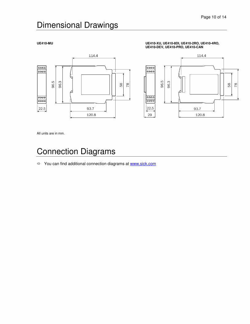
Dimensional Drawings
UE410-MU UE410-XU, UE410-8DI, UE410-2RO, UE410-4RO, UE410-DEV, UE410-PRO, UE410-CAN
All units are in mm.
Connection Diagrams You can find additional connection diagrams at www.sick.com
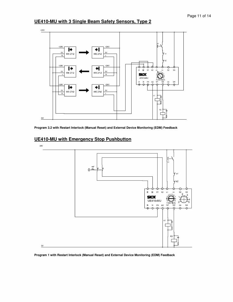
Page 11 of 14UE410-MU with 3 Single Beam Safety Sensors, Type 2
Program 3.2 with Restart Interlock (Manual Reset) and External Device Monitoring (EDM) Feedback
UE410-MU with Emergency Stop Pushbutton
Program 1 with Restart Interlock (Manual Reset) and External Device Monitoring (EDM) Feedback

Page 12 of 14UE410-MU with RE300 Non-Contact Safety Sensor
Program 2 with Restart Interlock (Manual Reset) and External Device Monitoring (EDM) Feedback
UE410-MU with Two-hand Controller (Type IIIC)
Program 4 without Restart Interlock (Automatic Reset) and External Device Monitoring (EDM) Feedback

Page 13 of 14UE410-MU with Two i11 Safety Interlocks – Independently Monitored
Program 8 with Separate Restart Interlocks (Manual Reset) and External Device Monitoring (EDM) Feedback
UE410-MU with Two IN4000 Safety Inductive Sensors
Program 3.2 with Restart Interlock (Manual Reset) and External Device Monitoring (EDM) Feedback

Page 14 of 14UE410-MU with C2000 Safety Light Curtain
Program 7 with Restart Interlock (Manual Reset) and External Device Monitoring (EDM) Feedback
UE410-MU with C4000 Safety Light Curtain and Two Sensor Muting
Program 3.1 with Restart Interlock (Manual Reset) and External Device Monitoring (EDM) Feedback