130177531 3g flexi wcdma flexi multi radio bts ppt
TRANSCRIPT

3G Flexi WCDMA BTS, Overview, Installation, Commissioning & Integration.

Nokia Siemens NetworksFlexi WCDMA BTS OVERVIEW

New way to build your 3G network
• Fits Nokia UltraSite EDGE BTS cabinet – easier site acquisition
• Faster, more economic roll-out
• Modularity with OBSAI - the future proof multi-radio BTS architecture
• Up to 60% lower energy consumption
Fits practically anywhere
• Small size and light weight
• A few module types can meet all site needs
New level of environmental performance
• Less BTS sites required
• Superior energy efficiency
• Safe use of material
Wall installation Pole installation Pile/Floor installation
Multimode Nokia UltraSite EDGE BTS & 19” rack Installation
Nokia Flexi WCDMA Base StationRevolutionary site concept

Wide Area high capacity WCDMA/HSPA BTS in micro BTS size
• Up to 12 carriers, 6 sectors
• Typical 43W output power
• Remote channel capacity upgrade and HSPA activation
Modular structure enables flexible expansions
– Radio and System modules as building blocks
– Optional AC Power supply & back-up and Transmission Hub module
Optimized Antenna Line
• Integrated power feed and control for Mast Head Amplifier and Antenna Tilt
133mm (3U)
447mm (19” rack)Less than 21kg
Outdoor –33 to + 55C, IP55
422/560 mm
2+2+2 BTSLess than 63kg
Nokia Flexi WCDMA Base Station Small and Modular

Modular BTS, installation options
For indoor/outdoor use > IP 55
Installation options:
Floor
Wall, Multiple units on wall
Rack
Stand or pole
Cabinet
Feederless (RAS05.1: 190 m / later: 15km)

Nokia Flexi WCDMA BTS tackles site related costs
OPEX• Power
• Site rent• Remote
capacity provisioningCAPEX
• Site implementation• Site construction
• Transmission
• Antenna system• Power system
How much can you save?
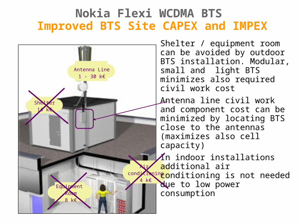
Air conditioning
4 k€Equipment
Room8 k€
Shelter14 k€
Antenna Line1 - 30 k€
Nokia Flexi WCDMA BTS Improved BTS Site CAPEX and IMPEX
Shelter / equipment room can be avoided by outdoor BTS installation. Modular, small and light BTS minimizes also required civil work cost
Antenna line civil work and component cost can be minimized by locating BTS close to the antennas (maximizes also cell capacity)
In indoor installations additional air conditioning is not needed due to low power consumption

RF Module
Optional Front and Back covers

Antenna 1Antenna 2
Antenna 4
Antenna 3
Antenna 1Antenna 2
Antenna 4
Antenna 3
External Interfaces of RF Module (Figure without the Casing)

RF Module Variants
RF Module variants supported in WN3.2
• FRGC: Flexi RF Module 2.1 GHz, Dual 50 WFRGD: Flexi RF Module 2.1 GHz, Single 50 W
• FRIA: Flexi RF Module 1.7/2.1 GHz, Dual 50 WFRIB: Flexi RF Module 1.7/2.1 GHz, Single 50 W
RF Module variants supported in WN3.3
• FRCA: Flexi RF Module 850 MHz, Dual 50 WFRCB: Flexi RF Module 850 MHz, Single 50 W
• FRDA: Flexi RF Module 900 MHz, Dual 50 WFRDB: Flexi RF Module 900 MHz, Single 50 W
• FREA: Flexi RF Module 1700 & 1800 MHz, Dual 50 W
FREB: Flexi RF Module 1700 & 1800 MHz, Single 50 W
• FRFA: Flexi RF Module 1900 MHz, Dual 50 WFRFB: Flexi RF Module 1900 MHz, Single 50 W
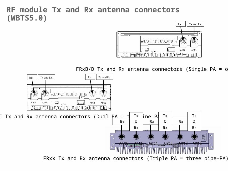
RF module Tx and Rx antenna connectors (WBTS5.0)
Ant 1 Ant 2
Tx and Rx Rx
Ant 1 Ant 2
Tx and Rx Rx
Ant 4 Ant 3
Tx and Rx Rx
FRxB/D Tx and Rx antenna connectors (Single PA = one pipe-PA)
FRxA/C Tx and Rx antenna connectors (Dual PA = two pipe-PA) Rx Rx Rx
Tx
&
Rx
Tx
&
Rx
Tx
&
Rx
Ant6 Ant5 Ant4 Ant3 Ant2 Ant1
FRxx Tx and Rx antenna connectors (Triple PA = three pipe-PA)

Flexi System Module + Transport sub-module

System module
FCM
TRS SubModule
BB Extension I/F
SUM & MUX
WSPCWSPCFSP
Control MCU+ Clock gen.
EAC, Clock I/O, Eth
PowerDistributionAssembly
Power supply module is responsible for the
distribution of 48VDC throughout the BTS
Transmission sub modulefor termination of the
BTS transmission
Control and Clock generation unit and the EAC, clock I/O ethernet
distribution interface
Baseband Extension interfaceto second system module
Summing and Multiplexing unit and up to three signal processing sub
assemblies (FSPA’s). The signal processing units are similar to the
WSPC unit
Three Optical Interface units for RF module interfacing
RF ModI/F
RF ModI/F
RF ModI/F
• Two hardware versions of the system module are available•FSMA – has only one FSPA unit and a processing capacity of 64 channel elements
•FSMB – has three FSPA’s and a processing capacity of 192 channel elements• The units are identical except that the extension module does not require the transmission
module• In extension mode only the baseband processing capacity of the extension module is used

System module - Release 2• Core assembly (new parts in blue)
– 1xFCMD Clock & Control sub-assembly– 1-3xFSPC BB sub-assembly– Core mechanics sub-assembly– 1xFPFB power sub-assembly– 1xFAN sub-assembly (same as rel1)– Connection cards (same as rel1 – except
FPF-FCM connection card)
• 1xCasing: (same as rel1)• 1xFTM: Transmission module (rel1 FTM is
compatible)– New FTM is developed for WBTS5.0 (not in
SM2 program scope)
Three SM R2 variants supported:• FSMC, 1 FSPC, 216 CE (WBTS5.0)• FSMD, 2 FSPC, 432 CE (WBTS5.0)• FSME, 3 FSPC, 648 CE (tentatively in
WBTS5.0)Compatibility• FCMD, FSPC and core mechanics is not
SM1 compatible• SM1 re-used parts, FPFB and FTM is SM1
compatible• SM2 is compatible with RFM1 and RFM2• SM2 HW is LTE capable – same HW for
LTE 1.0 SW release
System Module R2 (FSMC/D/E)
FSMC/D/E Y** and product contains FCMD/FSPC
(FSMC/D/E X** old protos contain FCMC/FSPB)

FlexiTransport Overview
FTPB (RAS05.1)
FTEB (RAS05.1)
FTJA (RAS06)
FTOA (RAS05.1ED
FTIA (RAS05.1)FTFA (RAS05.1)
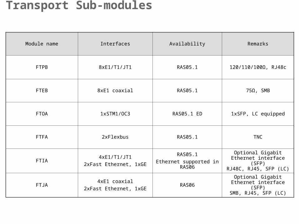
Module name Interfaces Availability Remarks
FTPB 8xE1/T1/JT1 RAS05.1 120/110/100Ω, RJ48c
FTEB 8xE1 coaxial RAS05.1 75Ω, SMB
FTOA 1xSTM1/OC3 RAS05.1 ED 1xSFP, LC equipped
FTFA 2xFlexbus RAS05.1 TNC
FTIA4xE1/T1/JT1
2xFast Ethernet, 1xGE
RAS05.1
Ethernet supported in RAS06
Optional Gigabit Ethernet interface (SFP)
RJ48C, RJ45, SFP (LC)
FTJA4xE1 coaxial
2xFast Ethernet, 1xGERAS06
Optional Gigabit Ethernet interface (SFP)
SMB, RJ45, SFP (LC)
Transport Sub-modules


Flexi Power Module FPMA
Example configuration with:
1 x Flexi Power Module FPMA
• 3 Flexi Power AC/DC sub-modules FPAA (230VAC -> 48VDC)
• 1 Flexi Power Battery FPBA
+-
48VDC output to BTS
AC input
cabling to FPMA
AC feed to FPAA (3pcs)

OBSAI Interface
OBSAI Interface
TransmissionTransport
OB
SA
I Inte
rface
Nokia Flexi WCDMA Base StationModularity is the key
Modularity with open OBSAI compatible interfaces enablesFaster time to market Economies of scaleFuture proofness
ProcessingBase band
OBSAI InterfaceRadio RF
OBSAI Interface Con
trol
Source: OBSAI

OBSAI reference architecture
OBSAI is multistandard (WCDMA/FDD, WCDMA/TDD, GSM/EDGE, …)• RP1: Clocks & Synchronization + Ethernet (control/management)
• RP2: 100M or 1Gbit Ethernet (physically same as RP1 c/m)
• RP3: OBSAI specified protocol, 768/1536/3072Mbps ) serial bus 8B/10B encoded with embedded clock. Frame structure optimized for air interfaces
• 48V power supply for all blocks/units
System module
FPF
FTM
FSP
FCM
FCM
FCM

HW Unit comparison between platforms
RF modules:
• FRxy Flexi RF Module Dual 50 W
• FRxy Flexi RF Module Single 50 W• Frequency variant (x):
C = 850, D= 900, E =1700 or 1800,F = 1900, G=2100, I = 1700/2100
• Number of carriers per RF module (y):A = 2 carriers, dual 50WB = 1 carrier, single 50W
C = 2 carriers, dual 50W / 2100D = 1 carrier, single 50W / 2100
• WAFA/B/I/J/H/G/M/N/T/W
• WPAI/J/C/D/H/K/M, WMPA/C/M
• WTRB/C/D/G
• WICA, WOCA/C
• WFCA/B/C/D, WUCM/A/B
• Bias-T
System modules: Baseband units:
• FSMA System module 1 FSP
• FSMB System module 3 FSP
• WAMA, WSMB, WSCA, WSPC, WMCM, WPSE
Transmission sub-modules: Transmission units:
• FTOA, FTPB, FTEB, FTFA, FTIA, FTJA • AXUA/B, AXCC/D, IFUA, IFUC, IFUD, IFUE, IFUF
Nokia Flexi WCDMA BTS Nokia UltraSite/MetroSite(50) WCDMA BTS

Nokia Flexi WCDMA BTS Build Up by Modules
Optional Outdoor cabinet
BTS SystemModule
Two PA RF Module
Two PA RF Module
Two PA RF Module
OptionalExtension System
Module (RAS05.1 ED)
AC-> DC BBUAC (Optiona
l)
SYSTEM MODULE:- C-plane processing + centralised timing- U-plane processing
+ multiplexing & summing- Ethernet switching
- Transport processing- External interfaces- Power Distribution
RF MODULE:- Modulator
- Channelizer- Analog RF processig
- Power Amplifier (integr.)
- Antenna filter (integr.)
Optical interfaces betweenthe modules

2x50 W RF Module
50 W RF Module
Sector 1
Sector 2
Sector 3
Site upgrade path to 2+2+2 (2nd of 2)
Cost Optimized Configuration COC (WN3.3)
30 W PA
TX1
TX1 & RX1
Div RX1
1+1+1 @ 20 W
30 W PA
Sector 1
30 W PA
TX1
TX3
Sector 2
Sector 3TX1 & RX1
Div RX1
TX1 & RX1
Div RX1
50 W PA
1+1+1 @ 40 W
40 W SW Licence
50 W PA
50 W PA
TX2
TX4
TX2
2+2+2 @ 20 W• 40W Power Licence +
• 2nd Carrier SW
Licence (RAS06)
• 1+1+1 @ 20/40 W
-> 2+2+2 @ 20 W
with minimum 3-sector RF Module configuration
• 2 x 50 W RF Module
• 50 W RF Module
• the same RF cabling
• no site visits
• Tx/Rx Carrier Centre Frequency Spacing = 5MHz
BTS SystemModule

50 W PA
TX1
Carrier TX1
RX1
Div RX1 1+1+1 @ 40 W50 W PA Div RX2
Carrier TX2
RX2
2+2+2 @ 40 W40W Power LicenseTX
3
3+3+3 @ 2x20
1x40 W (WN5.0)
& TX3
& RX3
& RX3
TX2
BTS SystemModule
2x50 W RF Module
2x50W RF Module
2x50 W RF Module
Sector 1
Sector 2
Sector 3
Sector 1 (2 and 3 identical)
Capacity upgrade path to 4+4+4 (2nd of 2)
Upgrade Optimized Configuration UOC (WN5.0)
Optional BB Extension System Module
• 1+1+1 @ 20/40 W
-> 2+2+2 @ 20/40 W
-> 3+3+3 @ 20 W
-> 4+4+4 @ 20 W
• with minimum 3-sector RF Module configuration
• three 2 x 50 W RF Modules
• the same RF cabling
→ no site visits
• Tx/Rx Carriers 1…4 inside 20 MHz sub-band
& RX4
& TX4
& RX4
4+4+4 @ 20 W
• 40W Power License
+
•2nd Carrier License
(WN5.0)
TX4

Nokia Siemens NetworksFlexi WCDMA BTS Installation
Objectives
After the completion of this chapter, the participant will be able to:
• Examine a Nokia Siemens Flexi WCDMA BTS for correct installation

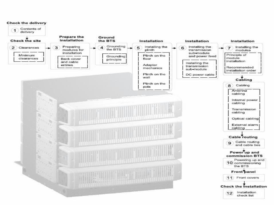
Work Order
Handling the modules and unpacking the
delivery
Preparing the modules for installation
Installing the stand-alone BTS on the
floor
Fixing adapter mechanics to plinth
Mounting the stand-alone BTS on the
wall
Mounting the stand-alone BTS on the
pole
Installing modules inside Nokia cabinet
Installing optional modules
Installing transmission sub-module
Grounding the BTS
Connecting external power feed

Handling the Modules and unpacking delivery
ESD ANTI-STATIC WRIST STRAPS SHOULD BE
WORN WHEN HANDLING ANY UNIT WHICH
DISPLAYS THE ESD LOGO
ESD ANTI-STATIC WRIST STRAPS SHOULD BE
WORN WHEN HANDLING ANY UNIT WHICH
DISPLAYS THE ESD LOGO
When handling the modules, always use the antistatic wrist strap as shown in the Connecting the antistatic wrist strap figure below. The cabinet must be grounded, otherwise the antistatic wrist strap will not work. Refer to Grounding the BTS section.

After mounting the Plinth, attach the site ground.
Handling the Modules and unpacking delivery

Unpack and check the delivery System Module
System Module
Front and Rear covers
External Cable Entry

Front and Rear covers
External Cable EntryRF Module
Unpack and check the delivery RF Module
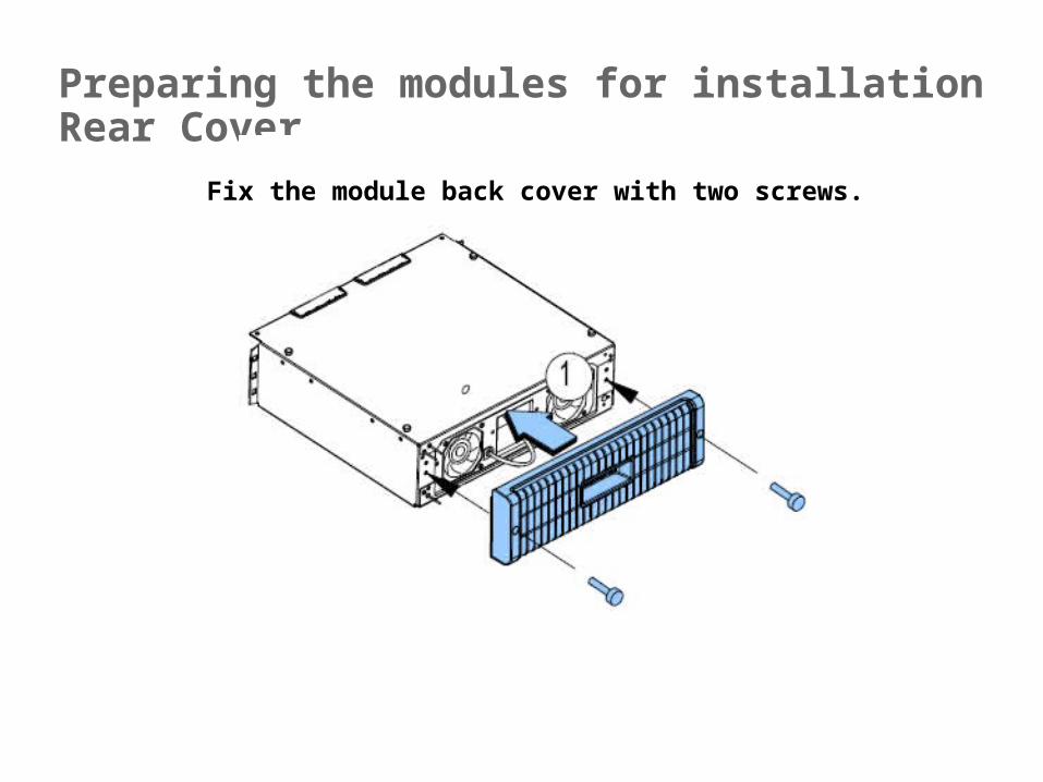
Preparing the modules for installation Rear Cover
Fix the module back cover with two screws.
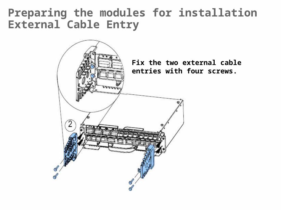
Preparing the modules for installationExternal Cable Entry
Fix the two external cable entries with four screws.

Supported Configurations

Clearances

Anchoring the plinth on the floor
Without maintenance Space With maintenance Space

Recommended installation order
Check that the plinth is installed correctly.
Actual stacking configuration may vary

Installing modules on the floor

Installation example: modules on the floor

Fixing adapter mechanics to plinth
Adapter mechanics brackets are installed on the plinth in wall and pole installations

Mounting the stand-alone BTS on the wall
A plinth is required for mounting the modules on a wall
Check that the plinth adapter mechanics are installed as instructed in Fixing adapter mechanics to plinth section.

Mounting a second plinth on the wall

Mounting the modules on a wall
One mounting plinth per two modules is installed on a wall. Refer to
Mounting the plinth on a wall for plinth installation instructions.

Mounting the stand-alone BTS on the pole
NOTE: There are different lengths of bolts and places for bolts in the bracket.

Mounting the plinth on a pole

Recommended module installation order
• Do not install more than two modules per plinth
• The modules must be installed with front panels facing left or right. Do not install modules so that the front panels face up or down.

Mounting the modules on the wall or pole
1 Tip
Line up the locating marks in the module to help aligning the holes with fixing studs.
4 Tip
Use the markings in the module to help aligning the holes with fixing studs.

Installing modules inside Nokia cabinet
690
1260
Front view
14U
14U
5U
5U
Flexi Outdoor Cabinet FCOA Flexi Indoor Cabinet FCIA

Installing optional modules
Flexi power module (FPMA) consists of connector blocks and four slots for
AC/ DC sub-module (FPAA) or battery sub-module (FPBA).
FPMA can include:
. two FPAAs and two FPBAs
. three FPAAs and one FPBA
. one FPAA and three FPBAs
. one FPAA and three free slots for expansion.


Grounding the BTS
When modules are installed inside a cabinet, separate module grounding is not required.
If the BTS has more than one plinth (for example in wall or pole installations), connect the main ground to one of the plinths and ground all the modules to that plinth.

Nokia Siemens NetworksFlexi WCDMA BTS Commissioning & Integration

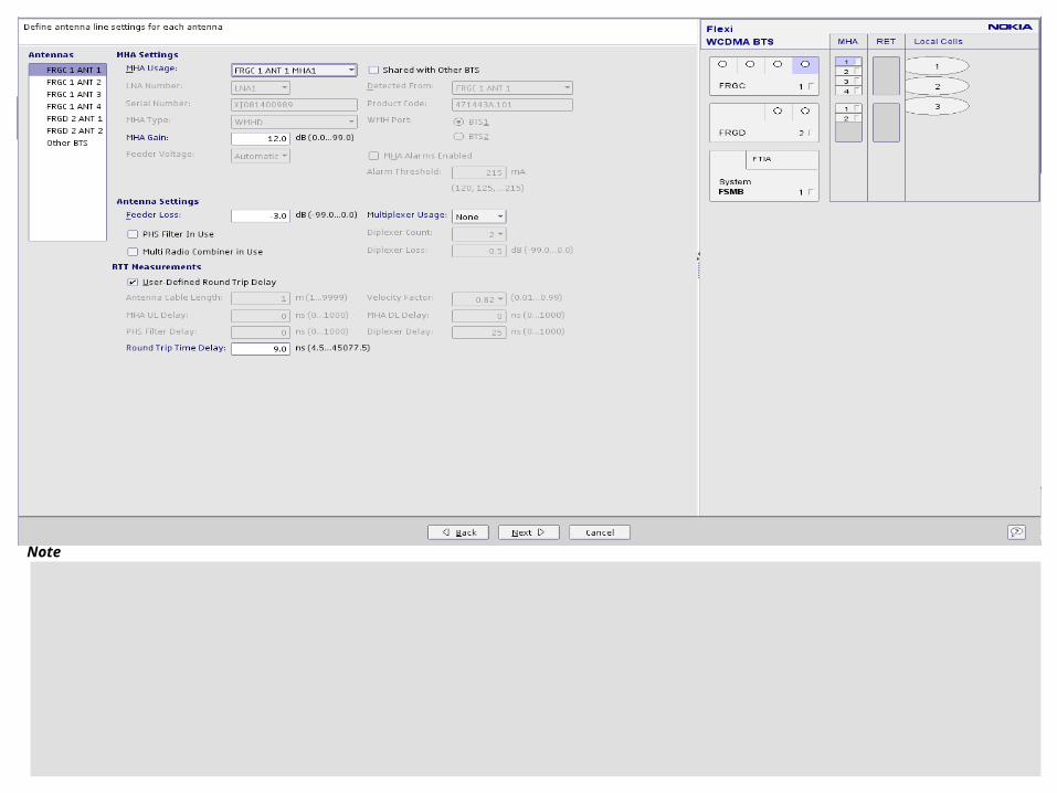
What should be do beforeCommissiong & integration?
What should I have befor Commissioning?


Note

Note

Note

Note

Note

Note

Note

Note

Note

Note

Note

Note

Note

Note

Note

Note
Note

Note

Note

Note

Tests Calls
Note

Thanks !