outfall maintenance and diversion plan
TRANSCRIPT

OUTFALL MAINTENANCE AND DIVERSIONPLAN
DEER ISLAND TREATMENT PLANTBOSTON, MASSACHUSETTS
MWRA CONTRACT NO. 6233TASK ORDER 15
FOR
MASSACHUSETTS WATER RESOURCES AUTHORITY
METCALF & EDDY, INC.WAKEFIELD, MA
AUGUST, 2000
ES-1
DEER ISLAND TREATMENT PLANT
OUTFALL MAINTENANCE AND DIVERSION PLAN
EXECUTIVE SUMMARY
The Deer Island Treatment Plant (DITP) Outfall Maintenance and Diversion Plan contained
herein has been developed in accordance with requirements stated in the final DITP NPDES
Permit No. MA 0103284. This permit requires the MWRA to maintain the existing harbor
outfall system to enable future flow diversion from Outfall TO1, if directed by the
Environmental Protection Agency and the Massachusetts Department of Environmental
Protection. The Outfall Maintenance and Diversion Plan consists of three distinct sections that
provide procedures for flow diversion, maintenance protocols for the existing harbor outfall
system, and shutdown and preservation procedures for Outfall TO1. The three sections of this
Outfall Maintenance and Diversion Plan are summarized below.
Flow Diversion Plan
The Flow Diversion Plan provides procedures for DITP effluent flow diversion from Outfall
TO1 to the existing harbor outfall system. This plan contains advance preparation requirements,
guidelines for the number of harbor outfalls necessary for diversion under various tide and flow
conditions, impact to plant process and support systems, gate line-up in the diversion flow path,
gate opening sequence, and estimated implementation time required to perform these activities.
Two flow diversion procedures are presented. The first procedure is direct diversion, where flow
is diverted in its entirety once required preparation activities have been implemented. The
second procedure is phased diversion that has been developed to support simultaneous capping
of the Outfall TO1 diffuser ports. The phased flow diversion procedure requires that a minimum
flow rate be maintained to Outfall TO1 during capping of the diffuser ports to minimize seawater
intrusion and potential for biofouling associated with a long-term shut down. Close coordination
between diving activities and plant operations is required to implement the phased flow
diversion.

ES-2
The recommended procedure is for direct flow diversion. This procedure reduces complications,
avoids flow monitoring and gate throttling required to maintain a minimum flow to Outfall TO1,
eliminates coordination between plant operations and diving activities for Outfall TO1, requires
a shorter implementation period, and is less costly than the phased flow diversion procedure.
Harbor Outfall System Maintenance Plan
The Harbor Outfall System Maintenance Plan provides maintenance protocols that would allow
for future activation of the existing near shore harbor outfall system in accordance with the
Outfall Maintenance and Diversion Plan. This plan includes short-term and long-term
maintenance protocols for periodic inspecting, equipment exercising, and outfall cleaning as
necessary.
The recommended maintenance protocol includes performing a baseline inspection of both
onshore and offshore system components shortly after this system is shut down. The results of
this inspection will form the benchmark to evaluate future sediment build-up and marine growth.
Annual inspections are recommended for onshore and offshore structures and components.
Results of the annual inspections will indicate the need for equipment maintenance, sediment and
marine growth removal, and additional capital equipment, such as plates or duckbill check valves
for the outfall diffusers.
Outfall TO1 Shutdown and Preservation Plan
The Outfall TO1 Shutdown and Preservation Plan prepared by Parsons Brinckerhoff Quade &
Douglas, Inc. provides procedures for securing and maintaining the deep ocean outfall during
extended idle periods subsequent to flow diversion to the existing harbor outfall system.
Short-term and long-term procedures have been developed to protect the outfall during idle
periods.
The short-term shutdown procedure would maintain Outfall TO1 in a ready mode with the
diffuser ports open. This procedure would allow seawater intrusion and the potential for marine

ES-3
growth inside of the diffusers over time. A dive inspection program would be instituted after an
initial 30-day period to monitor the rate of biofouling. The frequency of dive inspections would
be adjusted based on the rate of marine growth observed. If the dive inspections reveal
significant marine growth blocking an average 10-percent of the diffuser ports, the long-term
shutdown protocol would be enacted.
The long-term shutdown procedure would extend well over 30-days and involve capping the
diffuser ports. The diffuser port capping procedure could be accomplished either under phased
flow diversion or direct flow diversion. Diffuser port capping would prevent seawater exchange
and control the rate of marine growth inside the diffusers and tunnel. Marine growth could be
further controlled with periodic disinfection of the diffusers through chemical injection ports
provided with the port caps. The diving required for capping of the diffusers and chemical
injection would be a significant effort and subject to weather and seasonal constraints.
The recommended Outfall TO1 Shutdown and Preservation Plan is the short-term shutdown
procedure, followed by the long-term shutdown procedure after direct flow diversion to the
harbor outfall system. Due to the complexity and coordination required between diving activities
and plant operations, capping the diffuser ports under phased flow diversion is not
recommended.
TABLE OF CONTENTS
Page
EXECUTIVE SUMMARY....................................................................................................... ES-1
SECTION ONE - INTRODUCTION1.1 BACKGROUND...............................................................................................................1-21.2 OUTFALL SYSTEM CHARACTERISTICS ..................................................................1-21.3 ENVIRONMENTAL IMPLICATIONS...........................................................................1-4
SECTION TWO - FLOW DIVERSION PLAN2.1. ADVANCE PREPARATION ACTIVITIES...................................................................2-22.2. DIRECT FLOW DIVERSION PROCEDURE................................................................2-22.3 PHASED FLOW DIVERSION PROCEDURE................................................................2-62.4 IMPLEMENTATION TIME REQUIRED TO ACHIEVE FLOW DIVERSION .........2-122.5 FLOW DIVERSION RECOMMENDATIONS .............................................................2-13
SECTION THREE HARBOR OUTFALL SYSTEM MAINTENANCE PLAN3.1 EXISTING CONDITIONS...............................................................................................3-13.2 POTENTIAL IMPACTS ON THE HARBOR OUTFALL SYSTEM .............................3-53.3 RECOMMENDATIONS FOR HARBOR OUTFALL MAINTENANCE ......................3-6
SECTION FOUR - OUTFALL TO1 SHUTDOWN AND PRESERVATION PLAN4.1 OUTFALL DESCRIPTION..............................................................................................4-24.2 SHUTDOWN SCENARIOS.............................................................................................4-24.3 INSTALLATION OF DIFFUSER PORT CAPS .............................................................4-64.4 LONG TERM MAINTENANCE OF SEALED DIFFUSER PORTS .............................4-84.5 RECOMMENDATIONS ..................................................................................................4-8
APPENDIX A: Outfall 001 and 002 Duckbill Check Valve Details
APPENDIX B: Outfall TO1 Diffuser Port Cap Details

TABLES
Table 1.1: Deer Island Outfall System ComponentsTable 2.1: Direct Flow Diversion Sequence of Gate ActivationTable 2.2: Phased Flow Diversion Sequence of Gate ActivationTable 2.3: Estimated Implementation TimeTable 2.4: Estimated Implementation TimeTable 3.1: Existing Outfall CharacteristicsTable 3.2: Recommendations For Outfall System Components (October 29, 1993)Table 3.3: Recommendations For On-Shore Outfall Components (9/1/99)Table 3.4: Estimated Time To Design, Fabricate, And Install Plates or Duckbill Check ValvesTable 4.1: Diffuser Port Capping Under Discharge And No Discharge Conditions
FIGURES
Figure 1-1: Deer Island Treatment Plant Flow Percentile AnalysisFigure 1-2: Capacity Of Existing Harbor Outfalls 001 + 002Figure 1-3: Capacity Of Existing Harbor Outfalls 001 + 002 + 004Figure 1-4: Capacity Of Existing Outfalls 001 + 002 + 004 + 005Figure 2-1: Outfall Diversion Flow Path Through DITPFigure 2-2: Existing Outfall System ComponentsFigure 3-1: Existing OutfallFigure 3-2: MWRA Deer Island Related FacilitiesFigure 3-3: Outfall 002 Diffuser SectionFigure 3-4: Plan View of Outfall 002Figure 3-5: Section View of Outfall 002Figure 3-6: Section View of Outfall 002Figure 3-7: Outfall 001 Diffuser SectionFigure 3-8: Outfall 001 Diffuser SectionFigure 3-9: Internal Diameter Varies Between 84 And 42 InchesFigure 3-10: Diffuser Port Detail of Outfall 001Figure 3-11: Terminus Diffuser Detail Outfall 001Figure 3-12: Terminus Detail Outfall 004Figure 3-13: Plant OverflowFigure 3-14: Recommended Approach For Maintenance of Outfalls 001 and 002Figure 4-1: Recommended Approach For Shutdown and Preservation of Outfall TO1

SECTION ONE
INTRODUCTION
The Deer Island Treatment Plant (DITP) Outfall Maintenance and Diversion Plan has been
developed in conjunction with requirements contained in the final DITP NPDES Permit No. MA
0103284. The specific requirements stated in the permit are as follows:
“Prior to the use of outfall TO1, the MWRA shall submit a plan to EPA, MADEP, and OMSAP
for maintaining the physical integrity and capacity of the existing Deer Island outfall system, and
explaining how alternative discharge scenarios (including discharge through existing Deer
Island outfalls, if necessary) could be implemented. These alternative discharge scenarios must
be considered as an option under the MWRA’s contingency plan, within the section that outlines
a process for developing responses to any future problems. The MWRA shall maintain all
facilities in good working order to allow for reestablishment of a discharge through the existing
outfalls if deemed necessary.”
The plan contained herein, provides the protocol required to implement flow diversion if
necessary, maintains the integrity of the existing harbor outfall system, and protects the new
outfall if the MWRA is directed to perform a shutdown. The MWRA notes that EPA and DEP
considered the potential for flow diversion from Outfall TO1 to the existing harbor outfall
system to be remote, as stated in Part I.8.g. of the executive summary to this permit:
“From an environmental perspective, diversion of the discharge back into Boston Harbor would
be an option only if the Boston Harbor outfall provided superior water quality benefits or were
necessary to remedy other environmental harms, for example to prevent harm to protected
species. Because of the benefits provided by the outfall location in Massachusetts Bay in
providing dilution, mixing, and distance to shore, the possibility that diversion of the discharge
back to the Harbor would be environmentally desirable is remote.”
1-2
1.1 BACKGROUND
The location for Outfall TO1 was determined based on a comprehensive environmental impact
study conducted during the facilities planning phase of the Boston Harbor Project. The
statement cited above from the permit is consistent with the following statement made in Volume
V Section 1.3 of the March 31, 1988, Secondary Treatment Facilities Plan Final Report:
“The region represents the optimum mix of characteristics of good outfall sites. It is within the
large-scale circulation patterns of Massachusetts Bay, and therefore provides the most robust
long-term mixing. It is in an area of limited potential sediment accumulation, and thereby
avoids problems associated with concentrating pollutants in bottom sediments. It is located
away from intensely utilized near-shore resources, and thereby avoids the potential for
disruption.”
Outfall siting, sizing, and diffuser arrangements for optimizing dilution were developed and
modeled to provide a configuration with the least environmental impact on the deep ocean
receiving waters of Massachusetts Bay.
In conjunction with the Boston Harbor Project activities, the MWRA has conducted a 7-year,
pre-discharge monitoring program in the Massachusetts Bay receiving waters. This program,
overseen by an independent panel of marine scientists, is the most comprehensive marine
discharge-monitoring program in the United States. Baseline monitoring data will be used to
ensure that any impacts from the outfall are consistent with the small impacts anticipated in
environmental studies.
1.2 OUTFALL SYSTEM CHARACTERISTICS
Characteristics of new Outfall TO1 and the existing harbor outfall system components are
provided in Table 1.1. See Section 3.1 (Existing Conditions) and Section 4.1 (Outfall
Description) for additional detail on the respective outfall system characteristics.

1-3
TABLE 1.1: DEER ISLAND OUTFALL SYSTEM COMPONENTS
CharacteristicNew
Outfall
TO1 Total 001 002 004 005
Capacity, mgda 1270 400b 305b 95b closed closed
Capacity, mgda 1270 700c 242c 75c 383c closed
Capacity, mgda 1270 1100d 235d 73d 376d 415d
Length, ft 49,626 2565 2260 500 135
Diameter, ft 24.25 10 6.29 9.0 4 x 8e
Number of Open Ports 270 47 14 1 1
Port Diameter, ft 0.49-0.64 1.69 1.67 9 9
Port Discharge El, ft 0.00 54.7 54.7 97.8 98
Chamber Invert El., ft -271.0f 98.1 98.1g 98.1 103.2
Maximum Operating El.,ft 140.1f 120.0g 120.0g 120.0g 120.0g
Year Commissioned 1999 1959 1896 1959 1959
Notes:a Existing outfall capacity assumes current operating conditions. Capacity would be affected if the system were
modified or if significant sediment build-up or biofouling occurred once the outfall was inactive.b Outfall capacity at mean high tide (El. 110.5) with Outfalls 001 and 002 operating in parallel.c Outfall capacity at mean high tide (El. 110.5) with Outfalls 001, 002 and 004 operating in parallel.d Outfall capacity at mean high tide with all four existing outfalls operating in parallel. Note that flow diversion
reduces DITP effluent discharge capacity from 1270 mgd to 1100 mgd at this operating condition.
Outfall system capacity indicated would be reduced as tide levels rise above mean high tide (e.g., storm tides).e Existing 4-ft x 8-ft orifice in Chamber A slide gate was used to determine Outfall 005 hydraulic capacity.f New Outfall TO1 chamber elevations refer to Deer Island outfall shaft.g Existing outfall chamber elevations refer to onshore chambers.
The flows from the MWRA north and south systems were introduced to the DITP in January
1995 and July 1998, respectively. Plant operating data were evaluated to provide an indication
of the flow trends from the combined north and south systems over the past several years, and to
1-4
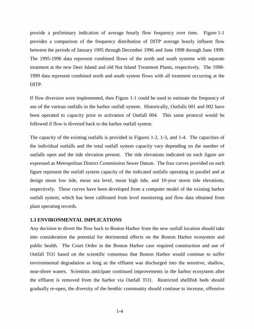
provide a preliminary indication of average hourly flow frequency over time. Figure 1-1
provides a comparison of the frequency distribution of DITP average hourly influent flow
between the periods of January 1995 through December 1996 and June 1998 through June 1999.
The 1995-1996 data represent combined flows of the north and south systems with separate
treatment at the new Deer Island and old Nut Island Treatment Plants, respectively. The 1998-
1999 data represent combined north and south system flows with all treatment occurring at the
DITP.
If flow diversion were implemented, then Figure 1-1 could be used to estimate the frequency of
use of the various outfalls in the harbor outfall system. Historically, Outfalls 001 and 002 have
been operated to capacity prior to activation of Outfall 004. This same protocol would be
followed if flow is diverted back to the harbor outfall system.
The capacity of the existing outfalls is provided in Figures 1-2, 1-3, and 1-4. The capacities of
the individual outfalls and the total outfall system capacity vary depending on the number of
outfalls open and the tide elevation present. The tide elevations indicated on each figure are
expressed as Metropolitan District Commission Sewer Datum. The four curves provided on each
figure represent the outfall system capacity of the indicated outfalls operating in parallel and at
design mean low tide, mean sea level, mean high tide, and 10-year storm tide elevations,
respectively. These curves have been developed from a computer model of the existing harbor
outfall system, which has been calibrated from level monitoring and flow data obtained from
plant operating records.
1.3 ENVIRONMENTAL IMPLICATIONS
Any decision to divert the flow back to Boston Harbor from the new outfall location should take
into consideration the potential for detrimental effects on the Boston Harbor ecosystem and
public health. The Court Order in the Boston Harbor case required construction and use of
Outfall TO1 based on the scientific consensus that Boston Harbor would continue to suffer
environmental degradation as long as the effluent was discharged into the sensitive, shallow,
near-shore waters. Scientists anticipate continued improvements in the harbor ecosystem after
the effluent is removed from the harbor via Outfall TO1. Restricted shellfish beds should
gradually re-open, the diversity of the benthic community should continue to increase, offensive

Figure 1-1: Deer Island Teatment Plant Flow Percentile Analysis
0
100
200
300
400
500
600
700
800
900
1000
1100
0.00% 10.00% 20.00% 30.00% 40.00% 50.00% 60.00% 70.00% 80.00% 90.00% 100.00%
Percentile
Ave
rage
Hou
rly F
low
, mgd
North + South System Hourly Flow Jan 95 - Dec 96
DITP Hourly Flow June 98 - June 99 South System Flow Diverted To DITP in June - 98

Figure 1-2: Capacity of Existing Harbor Outfalls 001 + 002
97
102
107
112
117
122
0 100 200 300 400 500 600 700
Effluent Flow, mgd
Cha
mbe
r B H
GL,
ft Tide El. 100.4 (MLW)Tide El. 105.6 (MSL)Tide El. 110.5 (MHW)Tide El. 114.4 (10-yr storm)Maximum Operating Level
Maximun Operating Level El. 120.0

Figure 1-3: Capacity of Existing Harbor Outfalls 001 + 002 + 004
110
112
114
116
118
120
122
300 500 700 900 1100
Effluent Flow, mgd
Cha
mbe
r B H
GL,
ft Tide El. 100.4 (MLW)Tide El. 105.6 (MSL)Tide El. 110.5 (MHW)Tide El. 114.4 (10-yr storm)Maximum Operating Level
Maximun Operating Level El. 120.0

Figure 1-4: Capacity of Existing Outfalls 001 + 002 +004 + 005
112
113
114
115
116
117
118
119
120
121
122
500 600 700 800 900 1000 1100 1200 1300
Effluent Flow, mgd
Cha
mbe
r B H
GL,
ft Tide El. 100.4 (MLW)Tide El. 105.6 (MSL)Tide El. 110.5 (MHW)Tide El. 114.4 (10-yr storm)Maximum Operating Level
Maximun Operating Level El. 120.0

slicks should disappear and eelgrass could return. Additionally, the potential risk to public
health from any failure of a treatment plant located so close to populated areas, however
unlikely, will be greatly minimized.
Diversion of the effluent discharge into Boston Harbor will threaten the continued recovery of
the ecosystem. One particular concern will be the effect of excess nitrogen on Boston Harbor,
which is presently eutrified and commonly has nuisance algae blooms and decreased water
clarity. Furthermore, a decision to divert must consider that the health of Boston Harbor’s large
estuarine system is integral to the health of the Massachusetts Bay’s ecosystem as a whole.
The decision to divert effluent flow to Boston Harbor must also take into account other
disadvantages of using the existing harbor outfall system instead of Outfall TO1. For example,
due to the greatly reduced chlorine contact time provided by the short outfalls relative to Outfall
TO1, significantly larger amounts of chlorine will be required to provide disinfection in the
harbor outfall system. Additionally the DITP dechlorination facilities that will be used with
Outfall TO1 discharge cannot be used with the existing harbor discharge. Also, the receiving
water dilution factors associated with the harbor outfall system components are significantly less
than those of Outfall TO1. Finally, the discharge capacity of the existing harbor outfall system is
less than the capacity of Outfall TO1, which will result in increased potential for combined sewer
overflows elsewhere in the sewer system.

3-1
SECTION TWO
FLOW DIVERSION PLAN
The Flow Diversion Plan consists of steps necessary to divert Deer Island Treatment Plant
(DITP) effluent flow from outfall TO1 to the existing harbor outfall system. Protocol includes
advance preparation activities, establishing the diversion flow path, identifying the gate line-up
and gate opening sequence, and estimating the implementation time required for flow diversion.
The flow path configuration and gate arrangement described in the flow diversion plan are
shown in Figures 2-1 and 2-2. These figures provide the equipment tag numbers referenced in
the gate line-up and gate opening sequence.
The Flow Diversion Plan would be implemented by the MWRA upon direction from the EPA
and DEP to shut down Outfall TO1. All on-island facilities involved in the flow diversion (e.g.
gates, stop logs, valves, etc.) will be regularly exercised and maintained. The Harbor Outfall
System Maintenance Plan developed to enable future flow diversion is described in Section 3. In
conjunction with the flow diversion, Outfall TO1 would be shut down and preserved for future
use. The Outfall TO1 Shutdown and Preservation Plan is described in Section 4.
The Flow Diversion Plan describes two distinct procedures (direct and phased) to achieve flow
diversion from outfall TO1 to the harbor outfall system. The direct flow diversion procedure
described in Section 2.2, diverts flow from Outfall TO1 to the harbor outfall system in one
continuous step. The phased flow diversion procedure described in Section 2.3, diverts a portion
of the total plant effluent flow to support Outfall TO1 diffuser port capping. Maintaining a
minimum flow rate through Outfall TO1 would minimize the amount of seawater intrusion
during capping of the diffuser ports. Minimizing seawater intrusion would in-turn minimize
marine growth potential within Outfall TO1 once diversion is complete and Outfall TO1 remains
idle for a period of time.

2-2
2.1 ADVANCE PREPARATION ACTIVITIES
Once the MWRA has been directed to divert flow from Outfall TO1 to the harbor outfall system,
necessary advance preparation activities will be initiated. These activities are identified below:
• Conduct a coordination meeting to review activities necessary to implement flowdiversion (e.g., staff and equipment resources, access requirements to align gates,lockout/tagout of gates).
• Review the flow diversion procedure and the associated implementation time required tocomplete each step.
• Perform a walk-through of the gate line-up and flow diversion sequence.
• Review the protocol for plant process and support systems impacted by flow (e.g., W3H,W3L, W6, effluent sampling, effluent disinfection flash mixing, disinfection basin scum,effluent dechlorination in Outfall TO1, outfall bypass conduit dewatering).
• Determine the number of harbor outfalls necessary to initiate the diversion based on tideand flow conditions.
• Check and calibrate the level monitoring equipment at Chamber B that would be used todetermine available outfall capacity and the need for additional outfalls to be placed inservice.
• Disinfect stored water present in the outfall box conduit with chlorine solution injectionsinto Chambers A, B, and C prior to removing isolation gates between chambers andoutfalls. This activity would disinfect the stored water in the isolated on-shore portion ofthe outfall system prior to discharge when the isolation is removed.
2.2 DIRECT FLOW DIVERSION PROCEDURE
The direct flow diversion procedure supports a shutdown of Outfall TO1 in a short time period.
This flow diversion procedure is independent of any Outfall TO1 diffuser port capping activities.
The flow path configuration, gate line-up, and sequence of activation established for direct flow
diversion are provided below.

2-3
Flow Path Established To Enable Direct Flow Diversion
The plant effluent flow path from the DITP to the existing harbor outfall system is shown in
Figures 2-1 and 2-2. This flow path consists of the following flow segments between the
disinfection basin influent channel and the harbor outfalls:
1. Plant flow from the disinfection basin influent channel enters Basins 1 and 2 through theassociated influent sluice gates and flash mixers.
2. Plant flow entering basin 1 passes northward to the end and exits the basin beneath thelaunders through the end sluice gates. The flow from Basin 1 then enters Basin 2 throughthe end sluice gates and passes through Basin 2 in the reverse direction (southward) tothe outfall bypass drop shaft.
3. Plant flow entering Basin 2 from the disinfection basin influent channel short circuitswestward to the outfall bypass drop shaft.
4. From the outfall bypass drop shaft (southwest corner of Basin 2), plant effluent passesthrough a pressure conduit segment to a riser shaft (adjacent to Reactor Battery A).
5. From the riser shaft (adjacent to Reactor Battery A), plant effluent passes southwardthrough an open channel conduit segment to a drop shaft (adjacent to Primary Battery D).
6. From the drop shaft (adjacent to Primary Battery D), plant effluent passes westwardthrough a pressure conduit segment beneath the length of the primary cross gallery.
7. From the primary cross gallery, plant effluent passes southward through a pressureconduit segment beneath Primary Battery D.
8. From beneath Primary Battery D, plant effluent passes westward through a drop shaft andpressure conduit segment to Chamber B.
9. From Chamber B, plant effluent is split between Chambers A and C. Dry weather flowsare discharged through Chamber C. Wet weather flows exceeding the capacity ofChamber C require activation of Chamber A and Outfall 005.
Direct Flow Diversion Gate Line-up and Sequence of Activation
The gate line-up and sequence of activation required to achieve flow diversion from the DITP to
the harbor outfall system are provided in Table 2.1. The gate opening sequence represents the
step-by-step process to be followed in order to implement flow diversion and address impacts on

2-4
TABLE 2.1: DIRECT FLOW DIVERSION SEQUENCE OF GATE ACTIVATIONSTEP ACTION LOCATION
Prepare Harbor Outfall System1 Remove stop logs Chamber B2 Remove stop logs Chamber C in 12 ft x 10 ft box conduit
3 Remove redundant stop logs Between Chamber C and Outfalls 001 and002
4 Check that sluice gate is closed Outfall 0045 Remove stop logs Between Chamber C and Outfall 0046 Remove stop logs Chamber A in 12 ft x 10 ft box conduit7 Remove redundant stop logs Between Chamber A and Outfall 005
8 Check that only one barrier gate remainsfor isolation Each of the four outfalls
9 Check that the liquid level is greater orequal to the centerline
Upstream of barrier gates * Equalpressure on both sides of the barrier gateswill assist in removal and prevent inrushof seawater and debris
10 Open sluice gate to equalize the pressure Outfall 00411 Remove barrier stop logs Outfall 00212 Remove barrier stop logs Outfall 001
13 Check that the flow path is clear and thatflow can be accommodated
From Chamber B to Outfalls 001, 002, and004
Isolate W6 System to Alternate Source and Sink
14 Open sluice gate [CE:W6.SG-2] Between W6 supply line and SecondaryClarifier Battery A effluent channel
15 Open sluice gate [CE:W6.SG-1] Between W6 return line and SecondaryClarifier Battery A effluent channel
16 Close sluice gate [HC:W6.SG-1]Between W6 supply line and plant waterbox adjacent to Disinfection EffluentChannel 2
17 Close sluice gate [HC:W6.SG-2] Between W6 return line and DisinfectionEffluent Channel 2
18 Install stop log sections [CA:BYP.RG-9]to crown elevation 136.0
Downstream end of Secondary Battery Aeffluent channel
Secure Hydropower Facility19 Stop turbines Hydropower Facility
20 Close bulkhead intake gates[DC:HTG.IG-1 and 2] Hydropower Facility
21 Dewater Isolated area of Hydropower FacilitySecure W3 System for Stop Log Removal
22 Open sluice gates[HC:W3.SG-1 and 2]
Between Disinfection Effluent Channel 1and plant water box
23 Open sluice gate[HC:W3.SG-3]
Between the plant water box and theburied 60-inch line to the outfall bypassdrop shaft

2-5
TABLE 2.1: DIRECT FLOW DIVERSION SEQUENCE OF GATE ACTIVATION(Continued)
STEP ACTION LOCATION
24 Close sluice gate[HC:W3.SG-4]
Between the outfall bypass drop shaftburied 60-inch line to the plant water box
25 Stop W3L pumping
* This will interrupt primary sludgedilution water to gravity thickeners, foamspray water to secondary reactors andclarifiers and LOX vaporizer water to theCryogenic Facility
26 Stop hose gate washdown activities ,pipeline pigging and flushing activities
Plantwide
27 Connect hose gates to create a W3Hrecirculation loop
Adjacent to the east side of Reactor A
outfall bypass conduit
28 Reduce W3H demand to one pump andstop remaining W3H pumps
* This will impact service to the hotflushing water, scum flushing water,sampler flushing water, plantwide pipingsystems, plantwide hosegates, andresiduals area polymer systems
29 Close sluice gates[DA:BYP.SG-1 and 2] Outfall bypass conduit
30Monitor W3H drawdown to support
removal of stop logs[CA:BYP.RG-2 and 10]
Bypass conduit between the drop shaft andriser shaft
31 Remove stop log [CA:BYP.RG-2] Bypass conduit32 Remove stop log [CA:BYP.RG-10] Bypass conduit
33 Open sluice gate [HC:W3.SG-4]
Between outfall bypass drop shaft andburied 60-inch line to the plant water box* This will initiate flow through the outfallbypass conduit and the supply W3manifold
34 Start W3H pumps to meet plant demand From PICS35 Start W3L pumps to meet plant demand From PICS
Checkout and Test Outfall Bypass Sampler
36 Test and calibrate final effluent sampler
Primary cross gallery adjacent to PrimaryBattery D. * This location has been usedfor final effluent monitoring for more than4 years
Secure the SBS System - Immediately prior to flow diversion
37Stop sodium bisulfite feed to Outfall T01and protect SBS System from associated
impacts
Disinfection gallery intermediate level andSBS valve chamber east of HydropowerFacility

2-6
TABLE 2.1: DIRECT FLOW DIVERSION SEQUENCE OF GATE ACTIVATION(Continued)
STEP ACTION LOCATIONInitiate Flow Diversion
38 Open sluice gates[DA:EFF.SG-1 and 2] Disinfection Basin 1
39 Open sluice gates[DA:EFF.SG-3 and 4] Disinfection Basin 2
40 Open sluice gates[DA:EFF.SG-9 and 10]
Between Disinfection Effluent Channel 1and Disinfection Effluent Channel 2 * Inorder to lower head in disinfection basinsprior to flow diversion
41 Open sluice gates[DA:BYP.SG-1 and 2]
Between Disinfection Basin 2 and theoutfall bypass drop shaft
42 Close sluice gates[DA:EFF.SG-9 and 10]
Between Disinfection Effluent Channel 1and Disinfection Effluent Channel 2 * Thisisolates flow from Outfall TO1 all flow isnow diverted
plant operation. Figure 2-1 and 2-2 show the equipment tag numbers provided for the gates
indicated in the sequence of activation. Some of the gates or activities included in this list may
constitute existing conditions and require confirmation only. The estimated implementation time
to complete the sequence of activation is provided in Section 2.4. Should plates be installed on
Outfall 001 diffusers, plates would need to be removed prior to start-up of the Outfall 001;
otherwise, flow would not exit the outfall. This will extend the estimated implementation time
of flow diversion.
2.3 PHASED FLOW DIVERSION PROCEDURE
Phased flow diversion to the harbor outfalls is performed to support capping of Outfall TO1
diffuser ports under flowing conditions. This procedure maintains a minimum flow to Outfall
TO1 and diverts the balance to the existing on-island outfalls. Capping of diffuser ports under
flow is an option discussed in Section 4 of this plan to minimize seawater intrusion into Outfall
TO1 during shutdown procedures. Phased flow diversion is dependent upon many factors and
could involve an implementation period of between three and six weeks to complete. Based on
this implementation time, required coordination with plant operations, and the diurnal and

2-7
weather related plant flow conditions, it is recommended that the hydropower facility be taken
off-line prior to flow diversion.
This procedure assumes all plant flow passes through Disinfection Basins 1 and 2 in parallel,
over the basin effluent weir crest El. 141.3, and bypassing the hydropower facility via the
overflow weir crest El. 139.5 to Outfall TO1. Therefore, the overflow weir crest would control
the liquid level in Disinfection Effluent Channel 1.
To initiate phased flow diversion, the connection between Disinfection Effluent Channel 1 and
the outfall bypass conduit would be made via the plant water box and 60-inch W3 line. The W3
sluice gate in the plant water box would be throttled to control the flow diversion and maintain
adequate flow to Outfall TO1 to prevent seawater intrusion. The capacity of the W3 line, is
approximately 130-mgd, corresponding to a 14-foot differential head between Disinfection
Effluent Channel 1 and the outfall bypass conduit adjacent to Reactor Battery A.
As the proportion of flow diverted to the harbor outfall system increases toward the capacity of
the 60-inch W3 line, one of the two 10-foot by 14-foot self-contained sluice gates isolating
Disinfection Basin 2 from the outfall bypass drop shaft could be partially opened. A 2-foot
sluice gate opening would equal the cross-sectional area of the 60-inch W3 line.
Flow Path Established to Enable Phased Flow Diversion
The phased diversion flow path is similar to that presented in Section 2.2 with the following
variations:
1. Plant flow from the disinfection basin influent channel enters Basins 1 and 2 through theassociated influent sluice gates and flash mixers.
2. Plant flow entering Basins 1 and 2 will pass northward to the end and exit the basins viathe effluent weirs at crest El. 141.3. The flow from Disinfection Effluent Channel 1 willenter the plant water box and 60-inch W3 line to the outfall bypass drop shaft.
3. Once the W3 line capacity is reached, one of the two sluice gates isolating DisinfectionBasin 2 from the outfall bypass drop shaft will be partially opened and continue to beadjusted in a controlled manner. This will allow plant flow entering Basin 2 from the

2-8
disinfection basin influent channel to short circuit westward to the outfall bypass dropshaft.
4. From the outfall bypass drop shaft (southwest corner of Basin 2), plant effluent will passthrough a pressure conduit segment to a riser shaft (adjacent to Reactor Battery A).
5. From the riser shaft (adjacent to Reactor Battery A), plant effluent will pass southwardthrough an open channel conduit segment to a drop shaft (adjacent to Primary Battery D).
6. From the drop shaft (adjacent to Primary Battery D), plant effluent will pass westwardthrough a pressure conduit segment beneath the length of the primary cross gallery.
7. From the primary cross gallery, plant effluent will pass southward through a pressureconduit segment beneath Primary Battery D.
8. From beneath Primary Battery D, plant effluent will pass westward through a drop shaftand pressure conduit segment to Chamber B.
9. From Chamber B, plant effluent will split between Chambers A and C. Dry weatherflows will be discharged through Chamber C. Wet weather flows exceeding the capacityof Chamber C would require activation of Chamber A and Outfall 005.
Phased Flow Diversion Gate Line-up and Sequence of Activation
The gate line-up and sequence of activation required to achieve phased flow diversion from the
DITP to the harbor outfall system are provided in Table 2.2. The gate opening sequence
represents the step-by-step process to be followed in order to implement flow diversion and
address impacts to plant operation. The equipment tag numbers provided for the gates indicated
in the sequence of activation are shown on Figures 2-1 and 2-2. Some of the gates or activities
included in this list may constitute existing conditions and require confirmation only. The
implementation time estimated to complete the sequence of activation is provided in Section 2.4.
TABLE 2.2: PHASED FLOW DIVERSION SEQUENCE OF GATE ACTIVATION
STEP ACTION LOCATION
Prepare Harbor Outfall System1 Remove stop logs Chamber B2 Remove stop logs Chamber C in 12 ft x 10 ft box conduit
3 Remove redundant stop logs Between Chamber C and Outfalls 001 and002
4 Check that sluice gate is closed Outfall 0045 Remove stop logs Between Chamber C and Outfall 0046 Remove stop logs Chamber A in 12 ft x 10 ft box conduit7 Remove redundant stop logs Between Chamber A and Outfall 005

2-9
TABLE 2.2: PHASED FLOW DIVERSION SEQUENCE OF GATE ACTIVATION(Continued)
STEP ACTION LOCATION
8 Check that only one barrier gate remainsfor isolation Each of the four outfalls
9 Check that the liquid level is greater orequal to the centerline
Upstream of barrier gates * This willassist in removal and prevent inrush ofseawater and debris
10 Open sluice gate to equalize the pressure Outfall 00411 Remove barrier stop logs Outfall 00212 Remove barrier stop logs Outfall 001
13 Check that the flow path is clear and thatflow can be accommodated
From Chamber B to Outfalls 001, 002, and004
Isolate W6 System to Alternate Source and Sink
14 Open sluice gate [CE:W6.SG-2] Between W6 supply line and SecondaryClarifier Battery A effluent channel
15 Open sluice gate [CE:W6.SG-1] Between W6 return line and SecondaryClarifier Battery A effluent channel
16 Close sluice gate [HC:W6.SG-1]Between W6 supply line and plant waterbox adjacent to Disinfection EffluentChannel 2
17 Close sluice gate [HC:W6.SG-2] Between W6 return line and DisinfectionEffluent Channel 2
18 Install stop log sections [CA:BYP.RG-9]to crown elevation 136.0
Downstream end of Secondary Battery Aeffluent channel
Secure Hydropower Facility19 Stop turbines Hydropower Facility
20 Close bulkhead intake gates[DC:HTG.IG-1 and 2] Hydropower Facility
21 Dewater Isolated area of Hydropower FacilitySecure W3 System for Stop Log Removal
22 Open sluice gates[HC:W3.SG-1 and 2]
Between Disinfection Effluent Channel 1and plant water box
23 Open sluice gate[HC:W3.SG-3]
Between the plant water box and theburied 60-inch line to the outfall bypassdrop shaft
24 Close sluice gate[HC:W3.SG-4]
Between the outfall bypass drop shaftburied 60-inch line to the plant water box

2-10
TABLE 2.2: PHASED FLOW DIVERSION SEQUENCE OF GATE ACTIVATION(Continued)
STEP ACTION LOCATION
25 Stop W3L pumping
* This will interrupt primary sludgedilution water to gravity thickeners, foamspray water to secondary reactors andclarifiers and LOX vaporizer water to theCryogenic Facility
26 Stop hose gate washdown activities ,pipeline pigging and flushing activities
Plantwide
27 Connect hose gates to create a W3Hrecirculation loop
Adjacent to the east side of Reactor A
outfall bypass conduit
28 Reduce W3H demand to one pump andStop remaining W3H pumps
* This will impact service to the hotflushing water, scum flushing water,sampler flushing water, plantwide pipingsystems, plantwide hosegates, andresiduals area polymer systems
29 Close sluice gates[DA:BYP.SG-1 and 2] Outfall bypass conduit
30Monitor W3H drawdown to support
removal of stop logs[CA:BYP.RG-2 and 10]
Bypass conduit between the drop shaft andriser shaft
31 Remove stop log [CA:BYP.RG-2] Bypass conduit32 Remove stop log [CA:BYP.RG-10] Bypass conduit
33 Open sluice gate [HC:W3.SG-4]
Between outfall bypass drop shaft andburied 60-inch line to the plant water box* This will initiate flow through the outfallbypass conduit and the supply W3manifold
34 Start W3H pumps to meet plant demand From PICS35 Start W3L pumps to meet plant demand From PICS
Checkout and Test Outfall Bypass Sampler
36 Test and calibrate final effluent samplerPrimary cross gallery adjacent to PrimaryBattery D. * This location has been usedfor final effluent monitoring for 4 years
Secure the SBS System – Immediately prior to flow diversion
37Stop sodium bisulfite feed to Outfall T01and protect SBS System from associated
impacts
Disinfection gallery intermediate level andSBS valve chamber east of HydropowerFacility

2-11
TABLE 2.2: PHASED FLOW DIVERSION SEQUENCE OF GATE ACTIVATION(Continued)
STEP ACTION LOCATIONInitiate Flow Diversion
With the hydropower facility off-line, the overflow weir crest El. 139.5 controls theliquid level in Disinfection Effluent Channel 1. The head differential created betweenthe plant water box and the outfall bypass conduit high point adjacent to ReactorBattery A allows flow diversion through the 60-inch W3 line. The W3 sluice gate inthe plant water box would be throttled to divert a portion of the flow to the harboroutfall system. A minimum flow of 200-mgd must pass through the Outfall TO1 toprevent seawater intrusion. Note that the W3 gate would need to be throttled to the10% open position when plant flow drops below 200-mgd.
38 Throttle sluice gate [HC:W3.SG-3]Between the plant water box and theoutfall drop shaft through the 60-inch W3line
At the assumed 14-foot differential head condition controlled by the overflow weirs,the sluice gate throttling positions, based on total plant flow, should be as follows:
Total Plant Flow, mgd Throttling Position, % OPEN
0-200 10201-300 20301-400 40401-500 100
Depending on diurnal flow conditions, this will allow capping of up to 50% of theopen diffuser ports.
39 Throttle sluice gate [DA:BYP.SG-1] Between Disinfection Basin 2 and outfallbypass drop shaft
Throttling of sluice gate DA:BYP.SG-1 is based on sluice gate HC:W3.SG-3 at 100%open and the following relationship between total plant flow and percent of diffuserports capped:
Total Plant Flow Diffuser ports Throttling Position Mgd % Capped % OPEN
501-900 25 10901-1000 25 201001-1100 25 30501-700 50 10701-900 50 20901-1000 50 301001-1100 50 50401-500 75 10501-700 75 20701-900 75 30901-1000 75 501001-1100 75 100

2-12
TABLE 2.2: PHASED FLOW DIVERSION SEQUENCE OF GATE ACTIVATION(Continued)
STEP ACTION LOCATION
A portion of the flow will short circuit from Disinfection Basin 2 to the outfall bypassdrop shaft when sluice gate DA: BYP.SG-1 is opened.
40
Close sluice gate [DA:BYP.SG-1] whentotal plant flow drops below 500-mgd andless than 50% of the diffuser ports havebeen capped. If more than 50% of thediffuser ports have been capped, thenthrottle sluice gate [DA:BYP.SG-1]
according to the table provided in Step 39.
Between Disinfection Basin 2 and outfallbypass drop shaft
41 Open sluice gates [DA:EFF.SG-3 and 4]Between Disinfection Basin 2 andDisinfection Effluent Channel 1 toequalize liquid level.
42 Open sluice gates [DA:EFF.SG-1 and 2]Between Disinfection Basin 1 andDisinfection Effluent Channel 1 toequalize liquid level.
43
Once all diffuser ports have been cappedwith Outfall TO1 flow discharging
through port cap nozzles, coordinate finalport cap nozzle closure with SBS carrierwater flowrate through parallel 10-inch
lines in to Outfall TO1.
SBS carrier water flowrate can becontrolled in the range 0-3,100 gpm tosupport final port cap closure.
43 Close sluice gates[DA:BYP.SG-9 and 10]
Between Disinfection Effluent Channel 1and Disinfection Effluent Channel 2* All flow is now diverted and OutfallTO1 is isolated from the plant effluentflow.
2.4 IMPLEMENTATION TIME REQUIRED TO ACHIEVE FLOW DIVERSION
The protocols provided to implement each method of flow diversion involve thorough
preparation and close coordination to carefully align and operate the required equipment. The
estimated duration for these activities for the direct flow diversion and phased flow diversion are
provided in Tables 2.3 and 2.4, respectively. Note that the gate opening sequence under the
phased flow diversion plan is coordinated with concurrent diving and diffuser port capping
activities.

2-13
TABLE 2.3: ESTIMATED IMPLEMENTATION TIME
REQUIRED FOR DIRECT FLOW DIVERSION ACTIVITIES
Activity Duration, days
Advanced Preparation 2 – 3
Gate Line-up 1 – 2
Gate Opening Sequence 2 – 4
Total Duration 5 – 9
TABLE 2.4: ESTIMATED IMPLEMENTATION TIME
REQUIRED FOR PHASED FLOW DIVERSION ACTIVITIES
Activity Duration, days
Advanced Preparation 5 – 10
Gate Line-up 1 – 2
Gate Opening Sequence* 14 – 28
Total Duration 20 – 40
* Concurrent diving and diffuser port capping operation
2.5 FLOW DIVERSION RECOMMENDATIONS
M&E recommends the direct flow diversion procedure to divert flow from Outfall TO1 to the
harbor outfall system based on the following points:
• Less time required to implement and complete compared with the phased flow diversionprocedure.
• Less effort and coordination required with plant operations resources compared with thephased flow diversion procedure.
• Eliminates the need for and difficulty associated with flow monitoring and throttling requiredby the phased flow diversion procedure to support capping activities.
• Less costly to implement compared with the phased flow diversion procedure.

3-1
SECTION THREE
HARBOR OUTFALL SYSTEM MAINTENANCE PLAN
3.1 EXISTING CONDITIONS
Outfall Components
The existing Deer Island Treatment Plant outfall system consists of a series of box
conduits, three junction chambers, and four outfall pipes. Figures 3-1 and 3-2 show the
layout and relative position of the various outfall components. The onshore components
are 12-foot-wide by 10-foot-high reinforced box conduits, which run between Chambers
A, B, and C in lengths of approximately 1,000 feet (A to B) and 1,500 feet (B to C). The
remainder of the system consists of Outfalls 001, 002, and 004 at Chamber C and Outfall
005 at Chamber A. (Outfall 003 was a temporary outfall that has been plugged and
abandoned.) The characteristics of the existing outfall components are shown in Table
3.1.
TABLE 3.1: EXISTING OUTFALL CHARACTERISTICS
Outfall Number
001 002 004 005
Length, feet 2,565 2,260 500 135
Diameter, feet 10.0 6.29 9.0 9.0
Discharge Elevation, feet 54.7 54.7 97.8 98.0
Number of Open Ports 52a 14 1 1
Port Diameter, feet 1.69 1.67 9.00 9.00
Chamber Invert Elevation, feet 98.1 98.1 98.1 103.2
Chamber Overflow Elevation, ft 120.0 120.0 120.0 125.0
Year Constructed 1959 1917b 1959 1959a – Five of the 52 ports are buried
b – Original brick outfall built in 1896; iron section in 1917
3-2
Most Recently Known Conditions
The most recently determined conditions of the existing outfall system are outlined in the
1992 lead design engineer’s Emergency Outfall Study (Metcalf & Eddy), the 1993 DP-38
project design engineer’s Existing Outfall Modifications Report (Sverdrup), the 1994 DP-
38 Outfall Crack Repair Inspection Report (Sverdrup), and the 1997 LDE Unprotected
Outfall Inspection (Metcalf & Eddy). Hydraulic and structural analyses performed
during the 1992 LDE study revealed that the outfall system routinely experienced
overstressing due to internal water pressures and external loadings. The 1992 study
recommended repairs to provide the hydraulic capacity for discharge of the new plant’s
peak flow. A detailed inspection program was then conducted under DP-38 the following
year. An inspection dive was performed on March 3, 1993, in Chambers A, B, and C and
the connecting conduits. Various cracks were discovered, along with concrete spalling,
concrete delamination, and bar support bricks dislodged from the top slab. The cracks
were described as hairline to 1.0-inch, mostly transverse to the tunnel axis and located
mostly on the slab extending down the walls, and between Chambers B and C. The
short- and long-term repair modifications recommended in the 1993 Existing Outfall
Modifications Report are outlined in Table 3.2. Recommendations that have been
implemented to date are shaded.
Repairs were performed on Chambers A, B, and C and their associated conduits between
February 11 and 24, 1994. Crack repairs were accomplished by injection of a
polyurethane chemical grout. The secondary deficiencies (dislodged bricks and concrete
spalling and delamination) were repaired using a polymer repair mortar. All cracks were
sealed, including a large floor crack near Chamber B. All areas of deteriorated concrete
were satisfactorily repaired. Deformation monitoring points for future reference and
inspection were installed at outfall station 10+50 (between stations 10+00 and 11+00, see
Figure 3-2). The 1997 follow-up inspection of the unprotected conduit between
Chambers A and B showed no change from the 1994 repairs.

3-3
TABLE 3.2: RECOMMENDATIONS FOR OUTFALL SYSTEM COMPONENTS (OCTOBER 29, 1993)
Outfall SystemComponent
Recommendations
Short Term (2-3 Years) Long Term (3+ Years)Unprotectedconduit betweenChamber A andChamber B
- Restrict backfill weight to 120 pcf.- Reduce future grade from Elevation 125 tp
Elevation 122- Install deformation monitoring points- Prohibit crane loading within 20 feet- Revise Guard House foundations
- Perform test borings and additional structuralanalysis
- Reinforce structures to sustain loads to moderncode criteria
- Extract concrete cores for testing
Protected conduitbetween ChamberA and Chamber B
- Repair cracks - Perform yearly internal inspections- Extract core samples for testing
Chamber A - Restrict construction loads, trucks and craneswithin 20 feet of structure
- Erect fence around Chamber A
- Reinforce structure to sustain loads to moderncode criteria
Chamber B - None - Modify vent shaftChamber C - Restrict construction loads, trucks, and cranes
within 20 feet of structure- Erect fence around Chamber C
- Construct wall across north side of chamberconnection to abandoned North Metropolitantrunk sewer
- Reinforce structure to sustain loads to moderncode criteria
- Prevent vehicles from passing over the top of thestructure
- Repair Outfall 002 brick manhole
Source: DP-38 Existing Outfall Modifications Report, Sverdrup Civil, Inc., 1993.Shading = recommendations implemented (as of July 1999).

3-4
Inspections of the diffuser sections of Outfalls 001 and 002 were performed between
July 26 and 29, 1994. The diffuser section of Outfall 002 has 13 “elliptical scoop”
diffuser ports of various sizes and one 48-inch terminus diffuser port (see Figures 3-3
through 3-6). This diffuser section was found to be nonfunctional because a 100-foot
section of the outfall conduit had been severed. Although the diffuser section showed no
physical defects, the interruption of effluent flow allowed the deposition of sediment and
marine fouling. The damaged section of Outfall 002 was repaired and the diffuser
section was cleaned out under a 1994 MWRA Sewerage Division contract. The brick
access manhole for Outfall 002, south of Chamber C, contains stop log grooves to isolate
the outfall. The manhole is in poor condition (cracked) and in need of repair and a cover.
In early May 2000, harbor observations in the area of the main Deer Island outfalls
indicated a suspected crack in Outfall 002. Staff proceeded to photograph the surface
waters above the main outfall and based on this information, to hire a contract diver to
inspect the external condition of Outfall 002. It appears from the video diver inspection
that a 3-inch crack (separation) approximately 60 feet long exists in the crown of Outfall
002. The crack is approximately 100 yards from the shoreline. There is effluent
percolating from the ground adjacent to the 60-foot section. This situation strongly
suggests other (below ground) cracks exist. The breached section was constructed in the
late 1800’s and is over 100 years old. This is the same outfall that was breached and
repaired several years ago. This new crack is in a different location on the outfall.
The diffuser section of Outfall 001 is constructed of extra-strength, precast, reinforced-
concrete, subaqueous-pressure pipe and is approximately 240 feet long. The outfall has
52 diffuser ports, 51 of which are 20-inch-diameter ports while the remaining one is a 30-
inch-diameter terminus port (see Figures 3-7 through 3-11). Five of the 20-inch ports
were reported as buried in the sediments at various locations along the length of the
diffuser section. The inspection also included an internal survey of Outfall 001. The
entire diffuser conduit was found to be without structural discrepancies and free of
sediment and debris.

3-5
Recommendations for the diffuser sections of Outfalls 001 and 002 included:
• No further inspection of Outfall 001 at the time of the report (December 1, 1994)
• Verification that the conduit stays buried
Outfalls 004 and 005 (see Figures 3-12 and 3-13) are visible at low tide and were
inspected in 1990 and 1991, respectively. The inspections indicated that the reinforced-
concrete pipes were in good condition and exhibited little marine growth and a small
amount of sedimentation on the invert of the pipe. A small area of Outfall 005 had
exposed rebar approximately 20 feet from the end of the outfall. Outfall 004 is used only
in wet weather and has an electric motor operator on the sluice gate. There is a custom-
fabricated slide gate (by DITP staff) installed at Chamber A, which reduces the flow
opening to direct flow towards Outfalls 001 and 002.
3.2: POTENTIAL IMPACTS ON THE HARBOR OUTFALL SYSTEM
The existing harbor outfalls will be shut down in conjunction with the start-up of Outfall
T1. Shutting off the flow to the harbor outfalls (001,002, 004, and 005) raises several
issues that should be addressed, in addition to the recommendations noted in Table 3.2.
The harbor outfall system must be maintained in the event that a future activation is
required. Biofouling of the diffusers, sediment build-up in the outfall pipes and around
the diffusers are potential causes of reduced capacity within the outfall system. Odor,
corrosion, system inspection and preventative maintenance of equipment are additional
issues that should be addressed. These issues are discussed below in the contexts of
short-term and long-term maintenance.

3-6
3.3 RECOMMENDATIONS FOR HARBOR OUTFALL MAINTENANCE
This section summarizes Metcalf & Eddy’s recommendations for maintenance of the
harbor outfall system. A full inspection of the onshore and offshore components of the
harbor outfall system is recommended as soon as practicable after the transfer of flow to
Outfall TO1 to definitively record the base conditions of the harbor outfall system by
component. The examination should focus on structural integrity and the presence of
biofouling or sediment. Specific recommendations for the onshore and offshore
components are described below.
Recommendations for Onshore Components
Dewatering of the onshore chambers and conduits is recommended prior to the baseline
and any further inspections to facilitate the most thorough evaluation possible of their
condition. Dewatering can be accomplished by installing stop logs into each outfall stop
log chamber to isolate the onshore components. A dewatering sump pump could then be
lowered into the outfall conduit through the access manhole adjacent to the west wall of
Primary Battery D. The onshore conduit system could be dewatered to El. 120.0 by
pumping the contents into Primary Battery D’s influent channel.
The installation of low-leakage, fiberglass stop logs in each outfall stop log chamber is
recommended as soon as practical once flow is diverted from the current outfall system to
the new ocean outfall. These stop logs will minimize the exchange of seawater in the
chambers and conduits and will isolate the onshore components of the outfall system
from the offshore outfall components. Standard wooden stop logs often have significant
leakage and swell when immersed, making them difficult or impossible to remove. DITP
staff recently procured reinforced-fiberglass stop logs with tightly sealing rubber gaskets
under CP-171 for isolation of primary clarifier effluent channels. Experience with this
type of stop log thus far at DITP, and at other installations surveyed, shows that the rate
of leakage is low (comparable to that of a gate). In addition, the installation and removal
of fiberglass stop logs can be accomplished with relative ease, which will be important

3-7
should the harbor outfall need to be brought quickly back on line. Stop logs and
associated stainless steel guides, need to be procured to fit the stop log grooves for each
outfall.
Recommendations for short and long-term maintenance of the onshore components are
included in Table 3.3. Other recommendations for the onshore components include
provisions to maintain the capacity of the existing outfall system. The system capacity
can be reduced by structural damage or by the intrusion of seawater, which can produce
biological growth. Chamber C is equipped with an electrically operated sluice gate for
control of flow to Outfall 004. Chamber A is equipped with an electrically operated slide
plate for control of flow to Outfall 005. This gate, at Chamber A, will be upgraded to an
electronically operated sluice gate as part of this plan. Monthly exercise of these control
elements is recommended. Additionally monthly exercise of the outfall by-pass conduit
effluent sampler and monthly inspection of the ultrasonic level sensors located at
Chambers B and C are recommended.
Recommendations for Offshore Components
Various options were investigated for the maintenance of the offshore components of the
harbor outfall after it has been shutdown. It is uncertain what degree of flow reduction

3-8
TABLE 3.3: RECOMMENDATIONS FOR ON-SHORE OUTFALL COMPONENTS (9/1/99)
On-Shore Outfall Components Short Term (1-2 Years) Long Term (2 Years to Year 2020+)Unprotected conduit between Chamber Aand Chamber B
− Take and record measurements fromformation monitoring points annually
− Perform Internal Inspection annually
− Perform additional structural testingand analysis as required as based uponinspection data
− Reinforce and/or repair existingstructures to sustain loads as regulated
− Perform internal inspections every2 years and when deformation isevidenced
− Perform annual external inspection offinished grade over conduit looking forsettlements or sink holes
Protected Conduit between Chamber Aand Chamber B
− Perform Internal Inspection annually− Repair cracks and other defects
revealed during inspections
− Same as Above
Chamber A − Perform Internal Inspection annually − Same as AboveChamber B − Perform Internal Inspection annually
− Modify vent shaft− Same as Above
Chamber C − Perform Internal Inspection annually − Same as Above− Construct wall across north side of
chamber connections to abandonedNorth Metropolitan Trunk Sewer
− Erect Fence around Chamber C− Repair Outfall 002 brick manhole

3-9
due to biofouling and sedimentation will occur in these outfalls with no action taken.
Careful monitoring will help the MWRA to determine the best course of action in the
future. Possible long-term action plans include no action, periodic cleaning of the
outfalls, or installation of duckbill check valves. The data collected from outfall
inspections will assist MWRA in determining the duration between subsequent
inspections and in evaluating the best long-term alternatives for these outfalls.
As noted above, an inspection of the offshore outfall components is recommended as
soon as practicable after transfer of flow to Outfall TO1 to determine their background
condition. Periodic inspections of the existing outfall pipes should then be performed to
assess any changes in their internal and external condition. Diving inspections should
assess the structural condition, degree of biofouling, and degree of sedimentation build-
up in and around the outfall pipes and support trenches. The diffusers and outfall
terminations should be cleaned and sediment excavated as necessary to maintain the
capacity of the system. Inspections of the internal components of the outfall system are
vital for determining the need for structural repair and sediment removal by mechanical
means such as vacuum removal.
Further recommendations for the offshore components of the harbor outfall system have
been separated into two categories: outfall pipes with a single terminus (004 and 005) and
those with multiple diffusers (001 and 002).
Outfalls 004 and 005
No action is recommended for Outfalls 004 and 005. Outfall 005 is commonly out of
service for durations of many months. Visual inspections of the outfall during these non-
service periods have indicated that little adverse sedimentation or biological growth has
occurred within the pipe. In addition, any accumulated sediment that has collected in the
invert of the pipe terminus has been effectively removed as the pipe was reactivated.
3-10
Annually inspections of Outfalls 004 and 005 are recommended to determine their
structural integrity and the degree of biofouling and sedimentation. If no significant
structural, biofouling, or sedimentation problems are noted in the first few inspections,
then increasing the period of time between adjacent inspections to at least two years is
recommended. Immediate repair of significant structural problems and/or removal of
significant quantities of biofouling or sediment is recommended if noted by inspections.
Outfalls 001 and 002
A multi-step approach is recommended for evaluating the long-term maintenance of
Outfalls 001 and 002. These outfalls are the most frequently used in the current harbor
discharge scheme and would be employed before Outfalls 004 and 005 during a complete
or partial flow diversion from the ocean outfall. Monitoring the structural condition and
degree of biofouling and sedimentation that occurs in Outfalls 001 and 002 after plant
flow has been diverted to the ocean outfall is recommended. Figure 3-14 outlines the
recommended approach for maintaining the flow capacity of these two outfalls.
The installation of plates or check valves is recommended if sedimentation or biofouling
significantly reduces the capacity of outfalls 001 and 002. Plates or check valves will
serve as a physical means of isolating the internal outfall system from the intrusion of
sediment and seawater. Duckbill-type check valves are recommended over the traditional
“flap-valve” tide gates. This approach would be consistent with the Nut Island outfall
contingency design by Montgomery Watson (formerly Havens and Emerson, the CP-152
project design engineer). Some of the advantages of the duckbill check valve are its non-
deteriorating rubber design and its inherent flexibility. Duckbill check valves typically
require only inches of line pressure to begin opening while they can withstand
backpressures greater than 50 feet. Duckbill check valves produce less headloss than
comparable flap-valve tidal gates and are not subject to blockage by debris. Pictures of
some duckbill check valves are shown in Appendix A.

Perform Diving Inspection (12 Months After Background Inspectio
Minor Capacity Reduction Maj
Re-inspect in 12 Months
Minor Capacity Reduction
Re-inspect in 12 Months
Re-inspect in 12 MonthMinor Capacity Reduction
Increase Duration to NextInspection Back to Top
Figure 3-14: Recommended Approach for Flow Capacity Maintenanc
- Minor Capacity Reduction < 20-25 % Above Background Sedimentation/Biofouling Levels- Major Capacity Reduction > 25% Above Background Sedimentation/Biofouling Levels
n)
or Capacity Reduction
Clean Out Pipe
s Install Plates or DuckbillValves
e for Outfalls 001 and 002

3-11
The duckbill-type check valve has been used extensively in sewage and stormwater
outfall applications and is available in sizes up to 108 inches. These valves can be
installed in a variety of orientations (vertical to horizontal). The duckbill valves could be
installed on Outfall 001 at the 30-inch terminus and at the 51 existing 20-inch diffuser
ports, which are oriented at 45-degree angles. The diffuser ports in Outfall 001 have a
9-inch lip on which the duckbill valves could be clamped (see Appendix A).
The “elliptical scoop” diffuser ports on Outfall 002 are irregular in depth and shape and
will require outfall modifications or custom valve configurations, if installation is even
feasible on the 82-year-old cast-iron pipe. Dimensional information for the Outfall 002
diffusers does not exist, and an assessment of the condition of the pipe is necessary to
determine if alterations are possible to accommodate the duckbill check valves. It is
therefore recommended that the initial survey of the outfall system (just after transfer of
flow to Outfall TO1) include collection of dimensional data for the Outfall 002 diffusers
and an assessment of the condition of the pipe. The Red Valve Corporation has provided
a sketch of how the duckbill valves could be installed on these “elliptical scoop” diffusers
(Appendix A). Should duckbill installation be determined to be too costly, evaluate the
use of plates to isolate the outfall. Note however, plate installation will extend the
estimated implementation time of the flow diversion.
If plates or duckbill check valves are to be installed on one or more of the outfalls, then
consideration should be given to the complete cleaning of the outfalls and their related
components prior to installation, as was done at Nut Island.
Once the decision is made to provide plates or duckbill check valves for one or more
outfalls, the design, fabrication, and installation steps would begin. The duration of each
of these steps would vary depending upon which outfall is involved. An average estimate
to complete each of these steps for the various outfalls is provided in Table 3.4.

3-12
TABLE 3.4: ESTIMATED TIME TO DESIGN, FABRICATE, AND INSTALL PLATESOR DUCKBILL CHECK VALVES
Outfalls 001 and 002Design 2-3 weeksFabrication 14-18 weeksInstallation 3 weeksTotal from NTP 19-24 weeks
NTP = Notice to proceed
SECTION FOUROUTFALL TO1 SHUTDOWN AND PRESERVATION PLAN
This section has been prepared by Parsons, Brinckerhoff, Quade and Douglas, Inc. (PB) to
identify the activities that are necessary for the shutdown of Outfall TO1. The shutdown of the
outfall tunnel for any period of time would be a costly and complex operation, and should not be
taken lightly. However, it does appear that the shutdown of the outfall is feasible. The shutdown
will require the diversion of the effluent from the new Massachusetts Bay outfall to the existing
inner harbor outfalls as described in Section 2.
Two distinct types of Outfall T01 shutdown scenarios have been established. The first is a short-
term shut down with the outfall remaining ready to restart and subsequent monitoring programs
to measure the extent of diffuser biofouling over time. The second is a long-term shut down
where the outfall is isolated from the ocean by capping of the diffuser ports. Diffuser port
capping can be accomplished both under effluent flow and no effluent flow conditions. Different
procedures for each type of shut down are included in this report.
An important aspect of this outfall preservation plan is the need for ocean diving. Diving in the
ocean can be very difficult if the weather does not cooperate. The bad weather typically occurs
from mid-October through to the late winter. Bad weather could impact three aspects of this
plan – any diving work in the vicinity of the risers necessary to shut the outfall down, any diving
work to inspect the diffusers once the outfall is shut down, and diving work associated with
outfall re-starting.
Shutdown procedures will vary depending on the duration and the potential for biofouling of the
diffuser ports. Once biofouling reaches a threshold level in a short-term shutdown, then cleaning
and capping of the diffuser ports would proceed. For purposes of this plan, the biofouling
threshold level would be established at a minimum 30-day period or an average 10-percent
blockage of the diffuser ports. If conditions allow, monitoring could be used to determine the
presence of indicator species. If no biofouling is observed that would interfere with the outfall or

4-2
diffuser operation, then this initial shutdown phase without capping of the diffuser ports could be
extended accordingly, pending subsequent monitoring.
Monitoring for biofouling would consist of observational dives to three representative risers to
visually examine the diffuser ports for biofouling. In addition, benthic sampling discs previously
placed by several diffusers could be retrieved to examine for biofouling in a laboratory.
4.1 OUTFALL DESCRIPTION
The new Deer Island outfall, Outfall TO1, is an approximately 50,000-foot long, 24.25-foot
diameter concrete lined tunnel with 55 riser pipes and associated diffusers, extending north-east
from Deer Island into Massachusetts Bay. The tunnel is approximately 240 feet below the sea
floor in the diffuser area. The diffuser portion of the tunnel is approximately 6600-feet long, and
reduces in diameter along its length from 24.25-feet to less than 5-feet at the easternmost end of
the tunnel (Riser locations 1 and 2). This reduction in size is necessary due to hydraulic
considerations of the tunnel. The riser pipes are 30-inch diameter fiberglass pipes encased in
cement grout. Each riser pipe has a diffuser cap located on the sea floor and contains eight
diffuser ports. The diffuser ports range in size from 0.492 to 0.644-feet in diameter (5.90 to 7.73-
inches). Each diffuser port is tapered from the inside to the mouth of the port. A precast concrete
cap and stone riprap protect all diffuser ports. The diffuser port caps are top be retained, cleaned
and stored following the start-up of Outfall TO1. Details of the outfall tunnel and diffusers are
located in Appendix B. (To see a hard copy of Appendix B, please call the MWRA
Environmental Quality Department at 617-788-4700.)
4.2 SHUTDOWN SCENARIOS
Based on the information available and the analysis performed during the design and subsequent
studies made for the startup of the Outfall TO1, the following shutdown scenarios have been
developed.
• Short-term Shutdowns

4-3
• Long -term Shutdowns
Short -Term Shutdown
Once the ocean outfall has ceased its flow, the intrusion of seawater creates a potential for the
fouling of the diffuser riser pipes, ports and eventually the outfall tunnel itself by
microorganisms and other marine growth. The likelihood and extent of biofouling are based on
seasonal considerations and on oxygen levels within the tunnel/riser system. Therefore, a short-
term shutdown scenario was developed based on the effects of seawater intrusion and on
minimizing the potential for fouling of the tunnel system. If it has been determined that the
potential for biofouling has reached a point that it would be detrimental to the maintenance of the
tunnel system, then a long term shutdown would be implemented. This decision would be based
on the monitoring of the site for biofouling.
The duration of the short-term shutdown will be dependent on the amount of seawater inflow and
the resultant potential growth of marine organisms. The process for the short-term shutdown is to
divert the flow from the ocean outfall to the inner harbor outfalls as described in Section 2. This
diversion will result in stagnant conditions in the Outfall TO1 tunnel and riser system. Under
these conditions seawater, which has a higher specific gravity than that of the freshwater
effluent, will flow down the risers and into the tunnel displacing the effluent. Any growth of
marine organisms in the diffuser system would likely take more than 30 days to occur. The
potential for development of marine growth is dependent on the extent of seawater intrusion and
exchange as well as on seasonal variations in the nutrients, dissolved oxygen concentrations,
temperature, and on the presence of colonizing life stages of certain marine organisms in the
seawater. Examples of potential biofouling populations of concern are subtidal species of
barnacles and blue mussels, which tend to form encrusting colonies on hard substrates. PB’s
review of the riser videotapes, showing the condition of the risers from 1992 to the spring of
1999, suggests that neither barnacles nor blue mussels have become established on the nozzle
caps.
A 30-day period has been set as a threshold for short-term shutdown during the most biologically
active time of the year in Massachusetts Bay, typically from April to October. Should the
4-4
shutdown occur after October, then the short-term shutdown scenario could be extended until the
end of March with no additional measures taken.
After the 30-day threshold has been passed during a short-term shutdown, a monitoring program
would be instituted. The monitoring program would investigate the presence of marine
organisms on the diffusers that could potentially reduce the Outfall TO1’s capacity. This
program would be performed, on a periodic basis, by a dive team conducting visual observations
at a representative number of risers. The investigations could also be performed by using a
remotely operated vehicle. Laboratory analyses of growth on benthic sampling discs would also
be used to determine the potential for biofouling. Based on the monitoring results, the decision
to perform the long term capping of the diffusers will be made and the appropriate measures
instituted.
Long -Term Shutdown
The long-term shutdowns would be for an indeterminate period of time, which is at a minimum,
longer than 30 days. A decision by the MWRA to cap the diffusers could follow a few scenarios:
• Immediate capping of the diffuser ports with effluent discharge
• Immediate capping of the diffuser ports with no effluent discharge
• Capping of the diffuser ports with no effluent discharge following a short term shutdown andsubsequent monitoring program
Capping of the diffuser ports while effluent is being discharged would be an option to be
performed at the MWRA’s discretion. The advantage of this method is that marine organisms
would have little opportunity to enter the outfall pipe and diffuser systems. However this method
is complex and requires the assistance of divers to re-install the caps. During some parts of the
year it may not be possible to have a dive team working on the outfall due to weather conditions.
During those times this option may not be available.

4-5
Capping of the diffuser ports with no effluent discharge would be done if the closure was an
extension of the short-term shut-down or if it is not possible to have a dive team on hand due to
bad weather at the required time of shut-down.
There are a total of 440 diffuser port caps, with eight located on each of the 55 diffusers. Each
diffuser is equipped with four types of port caps at the time of initial startup: one with a pressure
relief valve for air release during the charging of the system; one with a pressure gage for
monitoring the pressure rise during tunnel construction, indicating a leak in the riser seals; one
with a 5/16-inch hole drilled in it for backup air release purposes; and the remaining five ports
with solid caps. The exception to this are the port caps for Diffuser No. 1, at the extreme eastern
point of the tunnel, which consist of three pressure relief valves, one pressure gage, one cap with
a 5/16-inch hole drilled in it, and three solid caps.
The modifications to the port caps depend upon the anticipated method of capping the diffuser
ports. The modification of the diffuser caps for the long-term shut down will consist of the
addition of a 4-inch equivolume valve to facilitate the installation of the cap under pressure and
to allow for the long-term injection of chlorine as required. The valve will be capped with a
special cap and quick-disconnect hose connection to allow for water sampling or the periodic
injection of chlorine, if required.
If the diffuser port caps were to be re-installed after a period of shut down, then it would not be
necessary to modify all of the caps. The existing diffuser port caps with the air release valves
and the divers gage will be removed during the initial startup. Both of these types of diffuser
port caps could be modified by removing the existing mounting cups with the air release valve
and divers gage and then fabricating new mounting cups that would include a valve. This valve
could be fitted with a quick connect fitting that would permit the removal of water for testing or
for the injection of chlorine, if required. The diffuser port caps with the 5/16-inch diameter hole
could be sealed by installing a nut and bolt through the hole with sealing washers at each end.
These measures would provide for the outfall to be shut down while providing hydraulic access
to the diffuser, if required.
4-6
All of the diffuser port caps would have a new O-ring gasket installed in the gasket groove. This
is necessary since the existing gasket will have lost its ability to seal, and the reinstallation of the
caps will require a gasket that will allow for the easy compression of the gasket for the
underwater installation. The material chosen for the gasket is swelling polyurethane, a single
component material that will swell to 300-percent after 72 hours of submersion in water. This
gasket material will greatly reduce the time required to install the caps on the diffuser ports.
Details of the diffuser port cap modifications are located in Appendix B. (To see a hard copy of
Appendix B, please call the MWRA Environmental Quality Department at 617-788-4700.)
4.3 INSTALLATION OF DIFFUSER PORT CAPS
The diffuser ports would be sealed by installing caps in order to protect the interior components
of the diffuser, the risers, and the tunnel. The following outlines the procedures to be followed
when sealing the diffuser ports both with and without effluent discharge. If it is anticipated that
the outfall could be subsequently dewatered, then one cap with an air release valve must be
provided on each of the risers with three air release valves being installed on Riser No. 1. The
following typical procedures assumes that an air release valve will be required on each riser:
Sealing of Diffuser Ports with Effluent Discharge
The sealing of the diffuser ports during effluent discharge would be performed in the following
sequence:
• Start at Diffuser No. 55, at the nearshore end, and proceed to the offshore end of the outfalltunnel, at Diffuser No.1.
• Clean each diffuser port of any loose debris and marine growth.
• Install one diffuser port cap with the air release valve on each riser assembly.
• Remove the 4-inch pipe cap and quick disconnect valve; open the equivolume valve.
• Place each diffuser valve over the diffuser port and allow the flow to pass through the openvalve.

4-7
• Twist the cap until it seats and locks into position.
• After all of the diffuser port caps are in place on each diffuser, close all of the equivolumevalves and install the pipe cap and quick disconnect hose connection.
• Proceed to the next diffuser in an easterly direction repeating the same procedure at eachdiffuser to the eastern limit of the diffuser field.
Note: As the diffusers are capped the flow in the outfall must be closely controlled, by balancing
the flow from the outfall to the inner harbor outfalls as described in Section 2. This flow is to be
controlled to reduce pressure at the existing open diffuser ports to allow for placement of caps on
the diffuser ports. The suggested method of controlling the flow is to reduce the inflow to the
outfall in increments to be determined as the diffuser ports are sealed and closed. It is anticipated
that a flow reduction in increments of 10% would facilitate cap installation. By using the caps
with the open valves, the diffuser port capping process can be undertaken during normal Deer
Island flow rates. The number of dive teams required to close the diffuser ports in this manner
depends upon the needed speed to cap the nozzles. If a period of potential bad weather is forcast
then additional dive teams may be needed. Several dive teams will be necessary should it
become necessary to shut the outfall down quickly as a result of some environmental event.
Sealing of the Diffuser Ports with No Effluent Discharge
The sealing of the diffuser ports with no effluent discharge would be performed in the following
sequence:
• Start at Diffuser No. 55, at the nearshore end, and proceed to the offshore end of the outfalltunnel, at Diffuser No.1.
• Clean each diffuser port of any loose debris and marine growth.
• Install one modified diffuser port cap with a valve and an air release valve on each riserassembly.
• Install the other modified port cap with a valve in the closed position and quick disconnectconnection/cap in place.
• Install the remaining diffuser port caps comprised of blank port caps and the port cap sealedby the 5/16th bolt and washer at that riser.
• Proceed to the next riser in an easterly direction, using the same procedure at each riser aswas used at Riser No. 55, finishing at Riser No. 1.

4-8
4.4 LONG TERM MAINTENANCE OF SEALED DIFFUSER PORTS
The sealed diffuser ports would be inspected over the period of the sealed shutdown. This is
accomplished by the use of divers who would inspect the caps and diffusers on a regular
schedule. It is anticipated that the inspections would be on a yearly schedule, unless some event
would require more frequent monitoring.
Depending on the length of time the ocean outfall is shut down, it may be required that periodic
injections of chlorine be performed to minimize any maintenance of the tunnel system due to
biogrowth. The determination of the quantity and frequency of any injection and remedial work
for maintenance would be performed by the Authority.
4.5 RECOMMENDATIONS
This section summarizes PB’s recommendations for the shutdown and preservation of Outfall
TO1. First it is recommended that once the diffuser caps have been removed in conjunction with
the start-up activities of Outfall TO1 that the caps be retained, cleaned and stored for future use.
Additionally, it is recommended that the cap modification required for installation under no flow
conditions be performed before the caps are placed into storage. Modifying the caps ahead of
time will minimize the time required to cap the diffusers if needed.
Due to the level of effort, complexity, and environmental impact to the harbor described in
Sections 1, 2 and 4, Outfall TO1 should only be shut down after careful consideration of the
circumstances. Figure 4-1 outlines the recommended approach for preserving Outfall TO1
during short term and long term shutdowns.
If the outfall is shut down for a short period, then the implementation of a monitoring program is
recommended to determine if biofouling could interfere with the successful subsequent startup
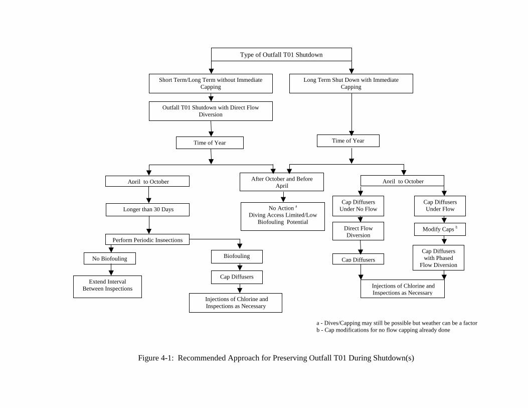
Time of Year
Outfall T01 Shutdown with DirDiversion
April to October
Perform Periodic Inspections
No Biofouling
Extend IntervalBetween Inspections
Biofou
Cap Dif
Injections of CInspections a
Short Term/Long Term without ICapping
Figure 4-1: Recommended Ap
Longer than 30 Days
s
p
ect Flow
After October and BeforeApril
No Action aDiving Access Limited/Low
Biofouling Potential
Time of Year
ling
fusers
hlorine and Necessary
April to October
Cap Diffuserswith Phased
Flow Diversion
Injections of Chlorine andInspections as Necessary
Modify Caps b
Type of Outfall T01 Shutdown
mmediate Long Term Shut Down with ImmediateCapping
roach for Preserving Outfall T01 During Shutdown(s)
Cap DiffusersUnder Flow
Cap DiffusersUnder No Flow
Cap Diffusers
Direct FlowDiversion
a - Dives/Capping may still be possible but weather can be a factorb - Cap modifications for no flow capping already done

4-9
and operation of the outfall. If this monitoring program identifies a significant potential for
biofouling of the system (an average 10-percent blockage of diffuser ports) then cleaning
followed by capping of the diffuser ports is recommended. Diffuser port capping would provide
a positive means to keep chlorinated fresh water in the tunnel and preclude nuisance species of
barnacles and mussels from entering the outfall. Diffuser port capping, after a monitoring
program, would be implemented under a no flow condition due to the fact that the flow has
already been diverted. In addition, if the monitoring program identifies a significant potential for
biofouling of the system, which would necessitate diffuser port capping, then it is recommended
that future shutdowns consider immediate capping of the diffusers to minimize this potential.
If diffuser port capping is to be implemented immediately as in the case of a shutdown with a
known long duration, then direct flow diversion is recommended followed by capping of the
diffusers under a no flow condition. Diffuser port capping under effluent discharge conditions is
not recommended due to the difficulty and complexity of cap modification, close coordination of
diving operations and plant operations required, and length of time required to complete the
diffuser port capping under flow. Table 4.1 summarizes the advantages and disadvantage of
capping the diffusers under effluent flow and no flow conditions.
Table 4.1: Diffuser port capping Under Discharge and No Discharge Conditions
Capping Scenario Advantages Disadvantages
Diffuser port cappingUnder EffluentDischarge Conditions
- Minimal seawater intrusion- Minimal biofouling potential- Reduced cleaning requirement
upon restarting of Outfall TO1
- Long duration to cap- Larger cost/duration for cap
modification- Higher cost of installation- Large coordination effort
required with plant operations
Diffuser port cappingUnder No EffluentDischarge Conditions
- Shorter duration to cap- Smaller cost/duration for cap
modification- Lower installation cost (half as
much)- Independent of plant operations
required
- Some seawater intrusion- Biofouling potential dependent
on season and saltwater exchange- Increased cleaning requirement
dependent on amount ofbiofouling