outer tracker off-detector readout and control discussion john coughlan slhc tracker readout meeting...
TRANSCRIPT

Outer Tracker Off-Detector Readout and ControlDiscussion
John Coughlan
SLHC Tracker Readout Meeting
March 7th 2007
Starting Assumptions
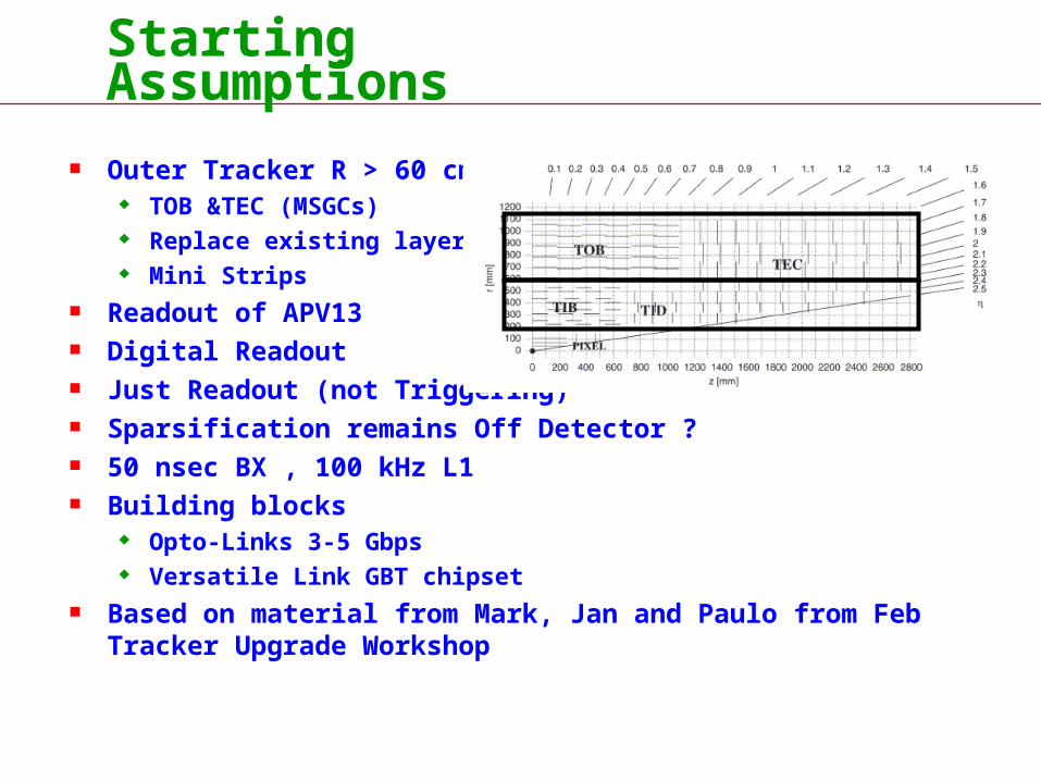
Outer Tracker R > 60 cm TOB &TEC (MSGCs) Replace existing layers Mini Strips
Readout of APV13 Digital Readout Just Readout (not Triggering) Sparsification remains Off Detector ? 50 nsec BX , 100 kHz L1 Building blocks
Opto-Links 3-5 Gbps Versatile Link GBT chipset
Based on material from Mark, Jan and Paulo from Feb Tracker Upgrade Workshop

Readout Channels
R > 60 cm 65% ~ 50 K APV25s ? 10 Luminosity with 50 nsec BX -> 20 x track density x 5 strips -> 4 x occ ~ 4% ~ 50K APV25 -> 250 K APV13

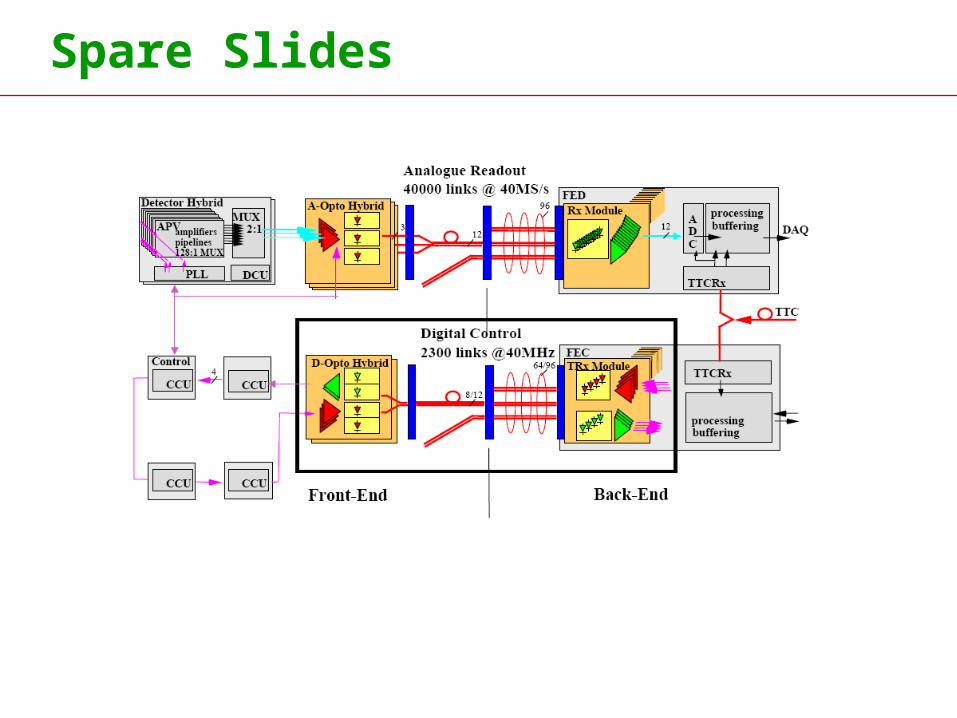
Data Tracker Links
Readout FED & Control FEC decoupled
40 K Uni Dir Pt2Pt links Data ~ 80K APV25 Synchronous System Latency not critical
FED APV

Mark : Further up the readout chain
digital link interface functionalityDAQ Functionmultiplexingencoding and fast serializationsparsification here maybe?
off-detector rate= (no.of FE chips) x 160 Mbits/s
digital header
128 analogue samples
APV O/P Frame
20 Ms/s readout -> 7 s
simple data rate / FE chip calculation
current APV data frame duration 7 sec for 140 samples
digitize at 8 bits -> 1120 bits to shift out in 7 sec => 160 Mbits/sec
e.g. 20 FE chips on one link= 3.2 Gbits/s raw data(no sparsification / no encoding)
if front end sparsification* (or faster links) then FE chips / link can increaseLoss-less Compression ?
160 Mbits/sec (per chip – no sparsification)
seriallinks 16
GBT

Readout Rates : Sparsification Off Detector
3.2 Gbps link @ 80% payload ~ 2.6 Gbps data APV13 128 ch -> 160 Mbps 16 x APV13 per GBT / link = 15 K GBT / links sFED : ORx 12 way x 8 ORx on 8U (feeding 8 x 12 MGBT FPGAs) Input : 96 links/MGBT x 2.6 Gbps ~ 250 Gbps / sFED (cf FED ~ 25 Gbps) Output (~4 x occ?) : / 10 -> 25 Gbps / sFED (cf FED 1.5 Gbps)
Total System ~ 250 K APV13 -> ~ 15 K links ~ 160 sFEDs ~ 10 sFED / ATCA crate -> 16 crates ~ 300 Gbps / crate ~ 2.5 Tbps to Filter Farm (cf FED 0.3 Tbps)
Still a BIG system.

sFED Possible Implementation
FPGASwitch
Off Detector sFED
SDRAMBuffer
SNAP 12
Rear Transition Module
STTC
10G SerialBackplaneDAQCrate Event Builder
12 x 3 Gbps
APV13
ATCA Crate 8U
Cntrl/Mon
PowerORx
FPGAsMGBTsGBT PHYMACSparsification1 per ORx
ORx and FPGA on Mezzanine?
Keep FEC functions separate
FED and FEC modules Communicate across backplane?
ORx
ORx
ORx
ORx
ORx
ORx
ORx
Mezzanine Prototype
GBT

TTC Controls Tracker Links
15 K Pt2Pt GBT links Data ~ 250K APV135 Non-Synchronous System Latency not critical
320 control rings 2,500 Bi Dir TTC + Control/Monitor EC TTC Latency critical
Upgrade 320 x 0.65 x 5 ~ 1,000 rings 8 K links Or bigger rings?
Pt 2 Pt
Pt 2 Pt

Jan : Best of Both Worlds? Broadcast downstream, Broadband upstream
oRxDAQ
FPGA
oTx
oRxeTRx
eTRx
eTRx
eTRx
oTx
oRx
oTx
oRx
oTx
oRx
oRxoRxoRx
oTxsplitter TTCFPGA
oRxprotocol
protocol
protocol
protocol In detectorFED
FEC
Far Fewer Links. Downstream PON. Don’t need upstream PON Every Data Link has dedicated TTC and Control. No more Rings. DAQ links no longer Synchronous (packets shared with EC mon) Couple Readout FED & Control FEC (EC cmds/mons)
Coupling
FE Module
Pt 2 Pt
PON

TTC Controls Tracker Links
15 K Uni Dir Data ~ 250K APV135 No longer Synchronous Data and Monitor EC
PON broadcast to 15K GBT ‘FEC’ has OTx only Each FE Hybrid has TTC/EC No more rings ‘CCU’ to chips via I2C
PON
Pt 2 Pt

Questions
Simplex Pt2Pt Broadband for Data and Monitoring How is this done? Protocols Can we maintain data rates with protocols?
I2C
16 x APVs
FED
FECFPGAs

Questions
Simplex PON for TTC and Control Splitting ratios? How many FEC links.
How to partition FED and FEC functions and inter communications?
What will FE modules look like? Assume Less Variations.
Do we need full FEC logic on Data Links (PD Off Detector?)
Consequences for Partitioning schemes?
What will new TTC system look like?
Assume New Emulators (keep in Global Trigger crate)

sFED/FEC
Integrate FEC functions on FED?
FPGASwitch
Off Detector sFED
SDRAMBuffer
MPT 12
Rear Transition Module
STTCTriggerThrottle
10G SerialBackplaneDAQCrate Event Builder
12 x 3 Gbps
sTTC
FPGAsMGBTsGBT RecvMACZS1 per ORx
APV13Monitor
ORx
ORx
ORx
ORx
ORx
OTx
ATCA Crate 8U
Cntrl/MonEthernet
PowerORx
ORx and FPGA on Mezzanine?

Final System Ideas New sDAQ (sFEDs connected direct to Filter via Super Event
Builder Network) New sTTC (Broadcasting Filter Addresses to FEDs) Crates
Just Mechanics, Power, Cooling. -> Control/Monitoring via Ethernet.
Serial Backplane based crates (Telecom ATCA , VME46?). Less Slots (but wider) Better Power & Cooling ? Better control & monitoring ? FED Event Builder Crate

First steps to sFED Year 1 : with FPGA Development boards Implement GBT receiver functionalities in FPGA fabric (Verilog models?) Channel density vs FPGA resources Fast FPGA Memory interfaces Implement protocols for extracting Data and EC Monitoring packets in
FPGA
Year 2 : Prototype sFED on small form factor Mezzanine? PCB Serial Integrity Issues ; Clock for FPGA MGBT Issues
Year 3 : Aim to instrument for full Tracker Readout chain test?
Learn from existing systems ; ECAL DCC, GCT, Tracker Trigger , other expts
Who else is looking at sFEDs? Common CMS solution? a la FEC
Get some experience with ATCA (other projects)
Other tasks
Front End Modularity?
sFEC module Trigger , Controls
Consider Sparsification On Detector ?

Spare Slides

Jan: Versatile Link: Definitions & GBT
oTx
oRxeTRx protocol

Readout Rates : Sparsification On Detector
/ 5? On Detector
Total System ~ 250 K APV13 ~ 15 K -> ~ 3 K links ~ 160 - > 80 sFEDs (limit of ATCA backplane switch) ~ 8 crates ~ 2.5 Tbps to Filter Farm (cf FED 0.3 Tbps)

Spare Slides (Coexisting) Options:
User interface: Simple parallel bus
User interface: Industrial standard buses
Possible industrial standards:• Ethernet• PCIe (memory mapped bus)• Hyper Transport (memory mapped)• …
Dedicated EC ASICor “Client” ASIC

Control Links :
Present System 320 CCU rings x 2 (redundancy) DOH x 4 links 2,560 links Half Tx and Half Rx @ 40 Mbps? ~ 40 FECs
80K / 320 ~ 250 APV25 / CCU ring 50 K APV25 -> 250 K APV13
Keep sFEC implementation separate from sFED Is there a need to broadcast additional TTC info to FEs?
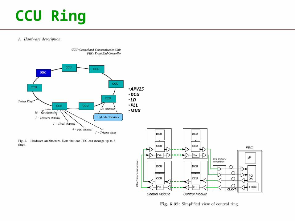
CCU Ring
•APV25•DCU•LD•PLL•MUX

Spare Slides
Spare Slides

Kostas: Tracker Partition
FED
FED
FED
FED
FEC
FEC
FED crate
FEC crate
TTCci
TTCex
FE modules
(xN)(xN)
(xN)
TTCoc
TrackerPartition
TTCoc
FEC
LTC
APVE
FMM
Compact PCI crate
TTC crate
FRLs
DAQ PC
x 9

Kostas: Tracker Partition
FED
FED
FED
FED
FEC
FEC
FED crate
FEC crate
TTCci
TTCex
FE modules
(xN)(xN)
(xN)
TTCoc
TrackerPartition
TTCoc
FEC
LTC
APVE
FMM
Compact PCI crate
TTC crate
FRLs
DAQ PC
x 9
?

CMS Optical Links webcms-opto:ecal-home
CMS Tracker CMS ECALDigital Control
Optical Link

Spare Slides
FPGA