ou-2016-2-1- development of non-proprietary uhpc mix
TRANSCRIPT

OU-2016-2-1- DEVELOPMENT OF NON-PROPRIETARY UHPC MIX
Quarterly Progress Report
For the period ending February 28, 2021
Submitted by:
PI- Royce W. Floyd, P.E., Ph.D.
Co-PI- Jeffery S. Volz, S.E., P.E., Ph.D.
Co-PI- Musharraf Zaman, P.E., Ph.D.
Graduate Student- Yana Dyachkova
Graduate Student- Stephen Roswurm
Graduate Student- Jacob Choate
Graduate Student- Trevor Looney
Graduate Student- Richard Campos
Undergraduate Student- Cole Walker
School of Civil Engineering and Environmental Science
The University of Oklahoma
Norman, OK
Submitted to:
ABC-UTC
Florida International University
Miami, FL

1. Background and Introduction
Ultra-high performance concrete (UHPC) is a relatively recent advancement in cementitious
composite materials with mechanical and durability properties far exceeding those of
conventional concrete, which makes it an ideal material for bridge deck joints. The research
project’s main objective is leverage efforts by all ABC-UTC partner institutions to develop a
non-proprietary UHPC mix design that will be labeled as “ABC-UTC Non-Proprietary UHPC
Mix”. The starting point will be two non-proprietary UHPC mixes developed by partner
universities, mainly at OU, and additional research described in this report is currently underway,
which will lead to development of the “ABC-UTC Non-Proprietary UHPC Mix”. The main
focus of the activity at OU is to investigate the effect of different fiber contents on the material
properties and bond performance of the “ABC-UTC Non-Proprietary UHPC Mix” and to
examine the repeatability of mix designs developed in different parts of the country. The OU
team is coordinating the overall effort of researchers at the five ABC-UTC partner institutions to
investigate material properties, bond strength, shear strength, and full-scale structural
performance of the “ABC-UTC Non-Proprietary UHPC Mix” developed by the partner
institutions working together.
Two mix designs developed by the partner institutions (one at OU and one at ISU) will be shared
with the other partner institutions for comparative testing with other well-established UHPC mix
designs. Fiber content and fiber type will be considered as primary variables for examining
material properties of the mix design. The primary objective is to develop guidance for an
“ABC-UTC Non-Proprietary UHPC Mix” made with local materials that can achieve the
necessary mechanical properties and durability for use in bridge component connections and
other applications, thereby providing an additional option for DOTs. Sharing of information
between the partner institutions allows for consideration of repeatability of the proposed mix
design and the combined efforts of the partner institutions will lead to more significant results
than could be obtained by any of the institutions working individually. Understanding the effect
of fiber type and content on material properties, bond, shear, and overall structural performance
will be used to identify the optimum fiber content required for the “ABC-UTC Non-Proprietary
UHPC Mix” to achieve the properties required for a given application. The study performed by
the OU team and primarily described in this report is focused on evaluation of material
properties and reinforcement bond behavior of the “ABC-UTC Non-Proprietary Mix” and will
synthesize results from the partner institutions to provide a “Guide for ABC-UTC Non-
Proprietary UHPC.” A technology transfer workshop, with participation of all five partner
institutions, is planned at the end of the project to disseminate findings of the proposed study to
the ABC-UTC stakeholders. In addition, the OU team will create a short course focused on
development and use of non-proprietary UHPC.
2. Problem Statement
Deterioration of bridges can often be related to poor performance of longitudinal connections or
transverse deck joints, which can be more frequent when precast panels are used for accelerated
bridge construction. Ultra-high performance concrete (UHPC) is a relatively recent advancement
in cementitious composite materials with mechanical and durability properties far exceeding
those of conventional concrete, which makes it an ideal material for bridge deck joints. It
combines a high percentage of steel fibers with an optimized gradation of granular constituents,
resulting in a compressive strength in excess of 22 ksi, a high post-cracking tensile strength, and

exceptional durability. The short reinforcing bar development lengths and exceptional durability
provided by UHPC lead to great potential for use in accelerated bridge construction and as a
repair material. All ABC-UTC partner institutions are considering the use of UHPC for bridge
deck joints. However, individual institutions are considering a number of other applications for
UHPC including: girder end region repairs (OU and ISU), bridge girder continuity connections
(OU), link slabs and existing joint retrofit (OU and ISU), UHPC shell retrofits for seismic and
non-seismic application and innovative UHPC based solutions (FIU), UHPC elements for
resisting seismic forces (UNR), and bridge deck overlays (ISU and FIU).
Many state DOTs have limited experience working with UHPC and do not have specifications
for non-proprietary UHPC mix designs. Proprietary UHPC formulations have proven
performance but can be very expensive. Guidance for use of UHPC class materials made with
local materials is needed to give state DOTs more options for use of this material in construction
and repair.
3. Objectives and Research Approach
The proposed study will coordinate the efforts of researchers at the five ABC-UTC partner
institutions, with primary focus on mix design, to investigate material properties, bond strength,
shear strength, and full-scale structural performance of non-proprietary UHPC developed by the
partner institutions. The mix design mainly developed at OU will be shared with the other
partner institutions for comparative testing with other well-established UHPC mix designs.
Researchers at ISU will also share their mix design to provide additional data point. The final
“ABC-UTC Non-Proprietary UHPC Mix” developed in this project will be evaluated at OU and
FIU by conducting a series of tests that has been recommended by FHWA for qualifying various
mix designs as UHPC. This report outlines the FHWA recommended material tests to be
conducted by OU and FIU and progress on conducting those tests up to this point.
The steel fibers used in typical UHPC mix designs are the most expensive component of the mix
design, and the high fiber contents typically recommended for UHPC may not be necessary for
every application. Fiber content and fiber type will be considered as primary variables for a
given mix design including consideration of 0%, 1.0%, 2.0%, 4.0% and 6.0% steel fibers by
volume and consideration of synthetic fibers. The primary objective of the project is to develop
guidance for an “ABC-UTC Non-Proprietary UHPC Mix” design made with local materials that
can achieve the necessary mechanical properties and durability for use in bridge component
connections, thereby providing an additional option for DOTs. Sharing of information between
the partner institutions will allow for consideration of repeatability of the “ABC-UTC UHPC
Mix” and the combined efforts of the partner institutions will lead to more significant results
than could be obtained by any of the institutions working individually.
Table 1 summarizes the efforts proposed by each partner institution and Figure 1 shows the
overall organization of the project.

Table 1. Research topics to be examined by each partner institution
Institution PIs Topic 1 Topic 2
University of
Oklahoma (lead)
Royce Floyd,
Jeffery Volz,
Musharraf Zaman
Development of the
final “ABC-UTC Non-
Proprietary UHPC
Mix” design,
conducting FHWA
recommended material
tests on final mix
design, and comparison
with other proprietary
UHPC mixes without
identifying them. Will
include examination of
material properties with
varying fiber content.
Examination of
reinforcing bar bond
strength in UHPC
with different mix
designs and fiber
contents using
pullout and beam
splice tests.
University of
Washington
John Stanton and
Paolo Calvi
Washington shear panel
test to investigate shear
strength of the “ABC-
UTC Non-Proprietary
UHPC Mix”,
considering different
fiber contents
Will test material
properties and send
local materials to OU
and ISU for testing.
Iowa State University Behrouz Shafei Durability of the
“ABC-UTC Non-
Proprietary UHPC
Mix”, with different
fiber types
Examination of
synthetic fibers.
University of Nevada
Reno
Mohamed
Moustafa
Panel joint testing with
the “ABC-UTC Non-
Proprietary UHPC
Mix”, considering
different fiber contents.
Will test material
properties and send
local materials to OU
and ISU for testing.
Florida International
University
Atorod
Azizinamini
Examination of material
properties of “ABC-
UTC Non-Proprietary
UHPC Mix”, with
varying fiber content.

Figure 1. Overall organization of project and information sharing
The UHPC mix design developed at OU is considered the base case for all testing. Researchers
from OU and ISU will provide UHPC mix designs developed at those institutions to the team
members at UNR, UW, and FIU for use in material and structural testing. OU and ISU will also
have the exact cementitious materials, aggregate, and admixtures used for each mixture shipped
to UNR, UW, and FIU so that each institution can exactly recreate the mix designs. OU and ISU
will provide a sufficient quantity of material for one of the proposed structural tests. For the
other tests, researchers at UNR, UW, and FIU will use their own local aggregates and materials.
Researchers at UNR, UW, and FIU will provide sufficient quantities of local cementitious
materials and admixtures to researchers at OU and ISU such that they can investigate the effects
of locally available cementitious materials and admixtures on the “ABC-UTC Non-Proprietary
Mix”. Researchers at OU and ISU will consider flowability, concrete compressive strength, and
modulus of rupture for comparison of the effects of local cementitious materials on mix design
performance. They will also conduct at least one set of bond tests (OU) and durability tests (ISU)
considering local cementitious variations provided by the other partner universities. In all cases,
researchers will obtain the same ½ in. Dramix steel fibers produced by Bekaert for use as the
base fiber case. Institutions sharing the exact materials will allow all institutions to begin their
work at the same time, without needing to wait for additional mix design development.
Each institution will provide a separate progress and final reports. OU researchers are
coordinating the research efforts and will compile a summary connecting the project reports that
can be published as the “Guide for ABC-UTC Non-Proprietary UHPC” at the end of the project.
Each institution will provide information for the Guide relative to their research along with a
short video describing the results of their research. The five institutions are holding bi-monthly
virtual meetings (two completed so far) to discuss project coordination, project progress, and to
resolve issues with using the different mix designs and obtaining constituent materials. A face to
face meeting was held at the Spring 2019 ACI Convention at the same time as the first virtual

meeting. Additional face to face meetings will be held at ACI conventions and ASCE SEI
congress if possible. A technology transfer workshop will be held during the fourth-quarter of
this study as part of the 2019 International Accelerated Bridge Construction Conference
sponsored by ABC-UTC in which each partner institution will share its results with the ABC-
UTC stakeholders. Materials required for teaching a short course focused on development and
use of non-proprietary UHPC will be developed incorporating the results of the project.
4. Description of Research Project Tasks
The following is a description of tasks and worked carried out to date.
Task 1 – Comparison of Local Materials Used in Mix Designs
Effects of UHPC constituent materials locally available to each partner institution and fiber
content on behavior of the “ABC-UTC Non-Proprietary UHPC Mix” will be considered using
material property tests recommended by FHWA for qualification of UHPC mix designs (Table
2). Mixtures will be tested with 0%, 1.0%, 2.0%, 4.0% and 6.0% fibers by volume
The OU research team has provided the final “ABC-UTC Non-Proprietary UHPC Mix” design
to the team members at UNR, UW, and FIU for use in their material property and structural
testing. Researchers at OU and FIU will conduct all tests listed in Table 2 for the “ABC-UTC
Non-Proprietary UHPC Mix” using locally available cementitious material and aggregates and
all fiber contents, while researchers at UNR and UW will perform all tests except for freeze-thaw
and creep tests on the final mix design. All material properties will be tested using a series of at
least three specimens and the methods listed in Table 2, with modifications necessary for UHPC
as specified in ASTM C1856 “Standard Practice for Fabricating and Testing Specimens of Ultra-
High Performance Concrete.” Creep tests will be conducted on 4 in. x 36 in. cylinders due to
capacity limitations of the existing creep frames. Total shrinkage beginning with placement of
the fresh concrete will be measured using a 6 in. x 12 in. cylinder with an embedded vibrating
wire strain gage (VWSG) in addition to drying shrinkage measured using ASTM C157. Direct
tensile strength tests will be conducted based on recommendations made by Graybeal and Baby
(2013) and Haber et al. (2018), but exact methods will be dictated by equipment available at each
partner university.
The OU team will have a quantity of the exact cementitious materials, aggregates and admixtures
used for the mixture constituents shipped to UNR, UW, and FIU so that each institution can
exactly recreate the mix designs for one of their proposed structural tests. For the other tests,
researchers at UNR, UW, and FIU will use their own local materials. Researchers at UNR, UW,
and FIU will provide local cementitious materials and admixtures to researchers at OU, such that
the OU team can investigate the effects of locally available cementitious materials and
admixtures on the “ABC-UTC Non-Proprietary Mix.” Flowability (ASTM C1437), compressive
strength (ASTM C39), and modulus of rupture of concrete (ASTM C78) will be tested by the
OU team for comparison of the effects of local cementitious materials on mix design
performance. The OU team will also conduct at least one set of bond tests considering variations
in local cementitious materials provided by the other partner universities. In all cases, the same ½
in. steel fibers produced by Bekaert will be used for consistency. Institutions sharing the exact
materials for large-scale tests will allow all institutions to begin their work at the same time,
without needing to do additional mix design development.

Table 2. Material property tests recommended by FHWA to be conducted on the “ABC-UTC
Non-Proprietary UHPC Mix”
Property Test Method Institution
Flowability ASTM C1437 All
Compressive Strength ASTM C39
ASTM C109
All
Modulus of Elasticity and
Poisson’s Ratio
ASTM C469 All
Splitting Tensile Strength ASTM C496 All
Flexural Strength ASTM C78 All
Direct Tensile Strength Based on FHWA
(Graybeal and
Baby, 2013, Haber
et al., 2018)
All
Total and Drying Shrinkage Embedded VWSG
ASTM C157
All
Compressive Creep ASTM C512 OU, FIU
Set Time ASTM C403 All
Freeze-Thaw Resistance ASTM C666 OU, FIU
Rapid Chloride Ion
Permeability
ASTM C1202 All
The base mix design for 2% fibers and the sources of all constituent materials used is included in
Table 3. Specimens for flowability, compressive strength, modulus of elasticity, splitting tensile
strength, flexural strength, direct tension strength, total and drying shrinkage, and set time have
been cast for the OU mix design using materials available in Oklahoma and for all fiber contents
(0%, 1%, 2%, 3%, 4%, and 6%). All mixes exhibited adequate flow with minor modifications to
the superplasticizer dosage during trial batching, except for the 6% fiber mix. Even with major
adjustments to the superplasticizer dosage almost zero flow was measured for this mix. The
material was workable in general, however, and could be placed in most specimen forms with
some difficulty. Use of a 6% fiber mix for more than laboratory testing would require more
extensive mixture modification.
Tests of the material property specimens at 28 days and 56 days have been completed for mixes
with Oklahoma materials and all fiber contents. Casting of the material property specimens is
shown in Figure 2, example compressive strength specimens (0% mix) are shown in Figure 3,
compressive strength results are shown in Figure 4, example splitting tensile strength specimens
(0% mix) are shown in Figure 5, and example modulus of rupture specimens (0% mix) are
shown in Figure 6.
Direct tension testing was completed. Three different test methods have been considered
including the FHWA test method and a dogbone type specimen. Proper alignment of the
specimens has been very difficult to achieve with the testing equipment available and several
modifications were required. Direct tension tests were conducted on the non-proprietary UHPC
using a test setup similar to that developed by Graybeal and Baby (2013) and Haber et al. (2018)
for steel fiber contents of 0%, 1%, 2%, 4%, and 6% by volume. Modifications to the test method
included using only two LVDTs to measure deformation instead of four, a load controlled rate,
and hinged grips at each end of the test specimen. A specimen in the testing machine ready for

loading is shown in Figure 7. Specimens with at least 2% steel fibers by volume exhibited some
strain hardening behavior, while specimens with no steel fibers or 1% by volume failed
immediately after the first crack appeared. A comparison of the direct tension testing results to
the splitting tensile strengths and flexural strengths is shown in Figure 8.
Creep specimens have been cast, loaded, and are still being monitored for all fiber contents. An
example loaded creep specimen is shown in Figure 9 and creep strain results out to more than
one year of age are shown in Figure 10. The 6 x 12 cylinder specimens with embedded vibrating
wire strain gages and ASTM C157 shrinkage specimens are being monitored continually. Figure
11 shows shrinkage strain results for the ASTM C157 specimens out to more than one year of
age.
Table 3. Baseline non-proprietary UHPC mix design
Material Quantity Specific Gravity Supplier
Type I Cement, lb/yd3
1179.6 3.15 Ash Grove Chanute,
Kansas
Slag, lb/yd3
589.8 2.97 Holcim,
South Chicago
Silica Fume, lb/yd3
196.6 2.22 Norchem
Ohio
w/cm 0.2 NA NA
Fine Masonry Sand, lb/yd3
1966 2.63 Metro Materials
Norman, OK
Steel Fibers, lb/yd3
255.2
7.85 Bekaert
(Dramix® OL 13/0.2) Steel Fibers, % 2.0
Superplasticizer, oz./cwt 18 1.07 BASF
(Glenium 7920)
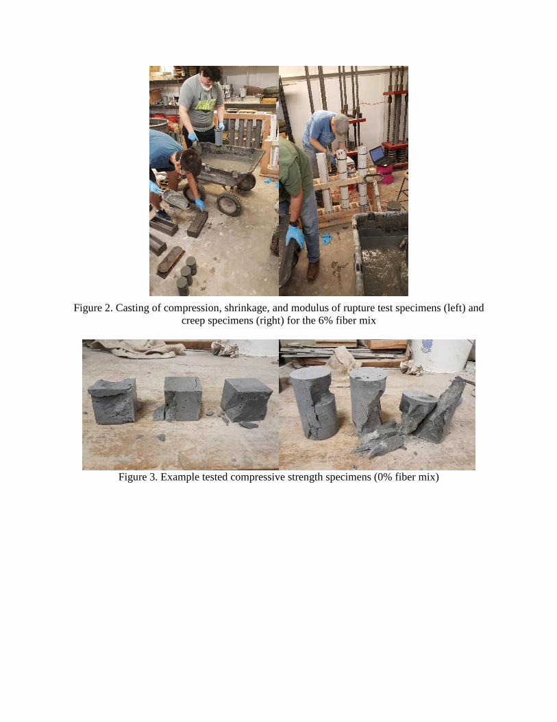
Figure 2. Casting of compression, shrinkage, and modulus of rupture test specimens (left) and
creep specimens (right) for the 6% fiber mix
Figure 3. Example tested compressive strength specimens (0% fiber mix)

Figure 4. Compressive strength results for cylinder specimens with different fiber contents
Figure 5. Example tested splitting tensile strength specimens (0% fiber mix)
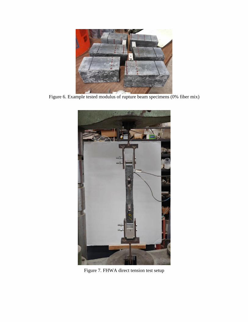
Figure 6. Example tested modulus of rupture beam specimens (0% fiber mix)
Figure 7. FHWA direct tension test setup

Figure 8. Comparison of FHWA direct tension test results to indirect tension tests
Figure 9. Example creep specimen immediately after loading (0% fiber mix)

Figure 10. Creep results for baseline mix design with different fiber contents
Figure 11. Shrinkage for each fiber content measured using ASTM C157
Set time tests were conducted following ASTM C403 for all mixture variations, but the steel
fibers affect the ability of the needle to properly penetrate the UHPC surface. An additional
series of set time tests were conducted using no fibers, but including the required adjustments to
superplasticizer content to determine if the superplasticizer is the controlling factor for set time
rather than fiber content. Figure 12 shows results of the revised set time tests, which indicate that
set time does increase with increase in superplasticizer dosage.
0
200
400
600
800
1000
1200
1400
1600
1800
2000
0 50 100 150 200 250 300 350 400 450 500
Cre
ep
Str
ain
(M
icro
stra
in)
Time (Days)
0% 1% 2% 4% 6%
-1800
-1600
-1400
-1200
-1000
-800
-600
-400
-200
0
0 56 112 168 224 280 336 392 448 504 560
Shri
nka
ge (
Mic
rost
rain
)
Time (Days)
6% Fibers 4% Fibers
2% Fibers 1% Fibers
0% Fibers

Figure 12. Results of ASTM C403 tests for set time with varying superplasticizer dosage
The FIU research team shipped fine sand, local cement, and slag cement to OU for testing. It was
determined that the silica fume and superplasticizer used by both institutions was from the same
source. UHPC mixes using constituent materials received from FIU were tested by the OU
research team. Trial batches to identify the required high range water reducer dosage were
completed first followed by batches for material testing. Flow was tested at time of casting and
compressive strength and flexural tension strength tests were conducted at 28 and 56 days of age.
A comparison of the superplasticizer demand for the different constituent materials and resulting
flow values are shown in Figure 13. The mixes using FIU materials required substantially larger
doses of superplasticizer to achieve the same flow. In general, compressive strength and modulus
of rupture were similar for mixes using materials from each location, as shown in Figure 14.
Figure 13. Comparison of superplasticizer dosage (left) and flow values (right) for mixes with
FIU and OU constituent materials
0
2
4
6
8
10
12
0 1 2 4 6
Flo
w (
in.)
Percent Fibers (%)
Adjusted Flow
OU FIU

Figure 14. Comparison of compressive strength (left) and modulus of rupture (right) for mixes
with FIU and OU constituent materials
Oklahoma constituent materials were shipped to UW for use in shear panel testing, to UNR for
comparative testing associated with slab joint testing, and to FIU for use in the workshop at the
ABC Conference and for limited comparative testing.
Task 2 – Evaluation of Reinforcing Bar Development Length in UHPC
Pullout bond tests on reinforcing bars and beam splice tests will be conducted to examine the
development length of reinforcing bars cast in the “ABC-UTC Non-Proprietary UHPC Mix”
using local materials with 1.0%, 2.0%, 4.0% and 6.0% fibers by volume. A proprietary UHPC
will also be tested for comparison as part of the matching funds project.
Reinforcing bar development length will be examined using a comparative pullout test to
identify the difference between required embedment for No. 3, No. 5, and No. 8 reinforcing bars
cast in the “ABC-UTC Non-Proprietary UHPC Mix” with varying fiber contents. Similar
specimens will be cast using established proprietary UHPC mix designs as part of the matching
funds project. Details for the pullout test specimens and setup used in previous research are
shown in Figure 15 (RILEM 1994). Bond between the reinforcing bar and the concrete occurs
only in the upper half of the concrete block, through the addition of a PVC or foam tube in the
lower portion, significantly reducing the effect of any confinement pressure generated as a result
of friction between the specimen and reaction plate. Data recorded during the test will include
load and free end slip at each end of the reinforcing bar. Since the pullout test is only useful as a
comparative measure, results of the pullout tests will be used to design a flexural beam splice test
to evaluate bond performance in a flexural loading configuration. The beam splice test will use
No. 5 and No. 8 reinforcing bars. Although there are a variety of bond and development length
testing protocols available, the beam splice specimen shown in Figure 16 is generally regarded as
the most realistic test method (ACI 408 2003, Ramirez and Russell 2008). The current AASHTO
LRFD design provisions for development length and splice length are based primarily on data
from this type of test setup (AASHTO 2014). Data recorded during the test will include load,
deflection, and strain in the reinforcing steel at each end of the splice.

Figure 15. Direct reinforcing bar pullout test setup with preliminary dimensions to be evaluated
further
Figure 16. Beam splice test setup with splice region still to be determined.
A trial series of pullout test specimens based on the specimen shown in Figure 15 and using No.
5 bars was cast and tested to evaluate the best embedment to produce a bond failure. The circular
specimens had a nominal 8 in. diameter to obtain a minimum cover of 3db for all bar diameters to
be tested. Embedments examined included 2db, 4db, 6db, 8db, and 10db with a debonded length
equal to the embedment length resulting in a specimen height dependent on the embedment. All
specimens except the 2db embedment specimen exhibited signs of reinforcing bar yielding and
the 2db embedment specimen exhibited a splitting failure, as shown in Figure 17. A set of revised
specimens were cast having a 2db embedment but larger overall specimen depth and resulting
debonded length in an attempt to prevent splitting failure. The revised specimens had the same 8
in. diameter, but total depths of 2.5 in. (2db debonded), 3.5 in. (3.6db debonded), and 5 in. (6db
debonded). Two specimens were cast and tested for each variable combination. All of these tests
resulted in pullout failures, so the final dimensions chosen for the pullout test were an 8 in.
diameter specimen with 2db embedment and 4db debonded length for a total depth of 6db, shown
in Figure 18. This resulted in a 3.75 in. thick specimen for the No. 5 bar tests, a 2.25 in. thick
specimen for the No. 3 bar tests, and a 6 in. thick specimen for the No. 8 bar tests.
Splice Region
4-Point Loading for Uniform Stress State in Splice Region
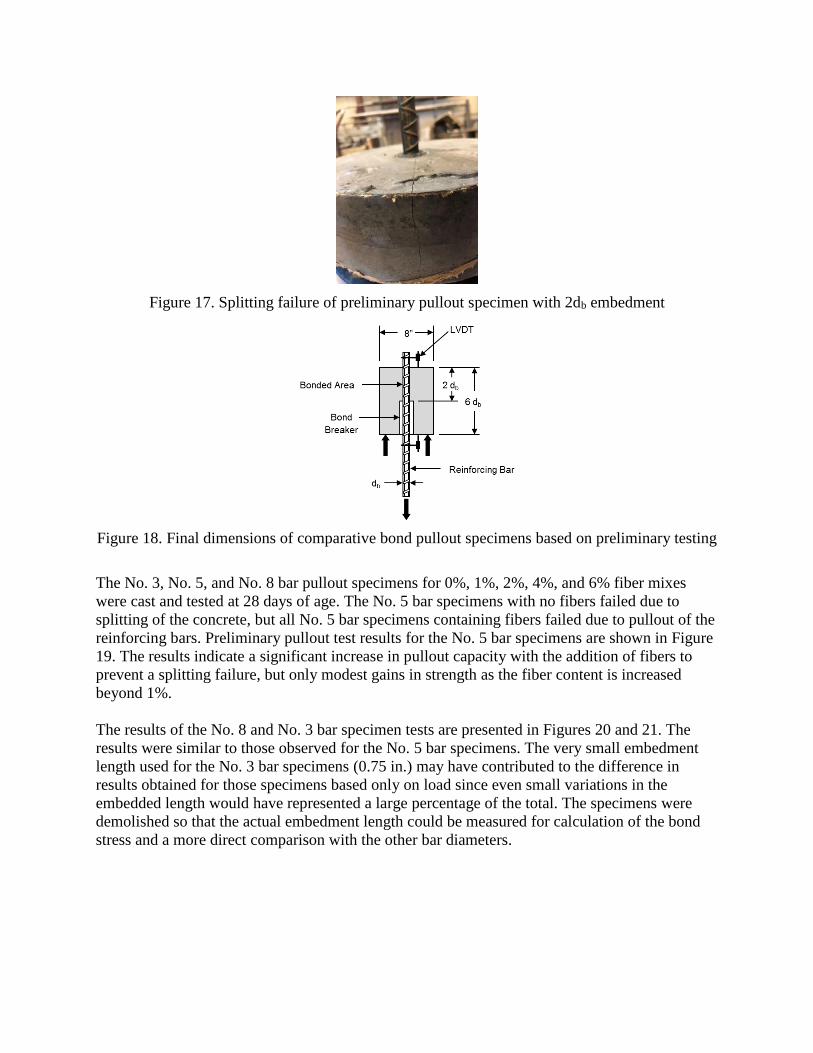
Figure 17. Splitting failure of preliminary pullout specimen with 2db embedment
Figure 18. Final dimensions of comparative bond pullout specimens based on preliminary testing
The No. 3, No. 5, and No. 8 bar pullout specimens for 0%, 1%, 2%, 4%, and 6% fiber mixes
were cast and tested at 28 days of age. The No. 5 bar specimens with no fibers failed due to
splitting of the concrete, but all No. 5 bar specimens containing fibers failed due to pullout of the
reinforcing bars. Preliminary pullout test results for the No. 5 bar specimens are shown in Figure
19. The results indicate a significant increase in pullout capacity with the addition of fibers to
prevent a splitting failure, but only modest gains in strength as the fiber content is increased
beyond 1%.
The results of the No. 8 and No. 3 bar specimen tests are presented in Figures 20 and 21. The
results were similar to those observed for the No. 5 bar specimens. The very small embedment
length used for the No. 3 bar specimens (0.75 in.) may have contributed to the difference in
results obtained for those specimens based only on load since even small variations in the
embedded length would have represented a large percentage of the total. The specimens were
demolished so that the actual embedment length could be measured for calculation of the bond
stress and a more direct comparison with the other bar diameters.

Figure 19. Pullout loads for No. 5 bar specimens with all fiber contents tested
Figure 20. Pullout loads for No. 8 bar specimens with all fiber contents tested

Figure 21. Pullout loads for No. 3 bar specimens with all fiber contents tested
Results of the pull-out tests were used to select the lap splice length used in the beam splice tests.
Beam splice test specimen construction was delayed due to difficulty in obtaining additional
steel fibers. New fibers were finally shipped and were received in March 2020. However, all
research laboratories at OU were shut down due to the COVID-19 pandemic in late March and
were closed until late May 2020. A staged reopening was begun in May, but the students
working on this task were not allowed back into the lab until July, which further delayed
completion of this task. Work began in earnest on these tests in the current quarter.
Splice beams were constructed for No. 5 bars with 1% and 2% steel fiber contents. The beams
had dimensions of 7 in. by 7 in., were 10 ft long, and were reinforced with two No. 5 bars with a
2db splice placed at mid-span. Foil strain gages were placed immediately outside of the splice
length to measure strain in the steel at the point of 2db embedment. The beams were loaded on a
9 ft span with loads placed at the third points as shown in Figure 22. Load was applied in 1 kip
increments up until the first flexural crack appeared and in 0.5 kip increments after the first crack
was observed. In all specimens the steel reached a strain corresponding to more than half of the
specified yield stress, but all beams failed due to bond in the splice region with a single crack
propagating through the entire beam depth at the splice location. The beams exhibited distributed
flexural cracking throughout the constant moment region, as shown in Figure 23.

Figure 22. Splice beam test setup
Figure 23. Cracking pattern for the non-proprietary UHPC splice beams
A comparison series of pullout tests using a proprietary UHPC material with 2% steel fibers was
conducted and the first set of beam splice specimens were cast using the same proprietary
material for comparison with the non-proprietary UHPC results. The proprietary UHPC
specimens had a higher bond stress, even when normalized by the compressive strength. In most
cases the pullout loads for the proprietary UHPC specimens exceeded the specified yield strength
of the bars with the 2db embedment used for the tests. Two splice beam specimens with No. 5
bars and 2% steel fibers were tested for comparison with the non-proprietary UHPC specimens
using the same methods. These beams also failed due to bond, but withstood higher loads and
exhibited fewer flexural cracks during testing. A photo of the beam crack pattern is shown in
Figure 24.

Figure 24. Cracking pattern for the proprietary UHPC splice beams
Figure 25 shows the load deflection curves for each of the six beams that made up the series of
splice beams tested with No. 5 reinforcement. Beams labeled D5 indicate proprietary UHPC with
No. 5 bars and those labeled J5 non-proprietary UHPC with No. 5 bars.
Figure 25. Load-deflection behavior of splice beams
First, it is apparent from Figure 25 that the proprietary UHPC beams reach the highest peak
loads, both attaining moments greater than 16 kip-ft. The non-proprietary UHPC beams with 2%
fibers reached between 12 and 13 kip-ft, and the non-proprietary UHPC beams with 1% fibers
reached the lowest peak moments of between 8 and 11 kip-ft. It is also interesting to note the
shape of the ascending curves towards the peak moments; the proprietary UHPC curves are
steepest, indicating the stiffest response, while the 2% and 1% non-proprietary UHPC beams are
progressively less steep, indicating that they were less stiff, or more compliant to the applied

load. Also of interest are the descending branches of the load deflection curves moving away
from the peaks. The proprietary UHPC beams shed load quickly after the bond failure at the
peak, which indicates an abrupt bond failure, while the non-proprietary UHPC curves roll over
more gently after reaching their maximum capacity. This may indicate that the bars in the non-
proprietary UHPC splices experienced more of a gradual bond slip instead of a sudden failure.
This behavior was noted in the direct pullout testing; whereas the No. 5 bars tended to pull out
suddenly from the proprietary and non-proprietary 2% fiber mixes with an audible sound and
jolt, the non-proprietary 1% fiber mix resulted in gradual pullout for all three specimens with no
audible signs of sudden failure.
Task 3- UHPC Durability Property Testing
In addition to the solid specimens described in Task 1, freeze-thaw testing will be conducted on
composite UHPC/conventional concrete specimens with 1.0%, 2.0%, 4.0% and 6.0% fiber by
volume. Freeze-thaw testing will be conducted according to ASTM C666 (2015) on a minimum
of three rectangular prism specimens for each UHPC fiber content.
As part of the matching funds project, freeze-thaw and permeability testing will be conducted on
both the proprietary UHPC and “ABC-UTC Non-Proprietary UHPC Mix” and the results
compared to the durability properties of conventional concrete. Freeze-thaw tests will be
conducted on each UHPC mix design. Rapid Chloride Ion Permeability (RCIP) tests based on
ASTM C1202 (2017) and freeze-thaw tests will also be conducted on each UHPC and
conventional ODOT Class AA concrete. A minimum of four RCIP specimens will be tested for
each mix design. Specimens will be cut from 4 in. x 8 in. (100 mm x 200 mm) cylinders for
testing at 28 and 90 days of age.
Rapid chloride ion permeability tests were conducted on the base mix design with 0% fibers and
a commercially available UHPC at 28 and 90 days. The steel fibers impede the testing method
and other fiber contents will not be tested. These results indicate similar performance to the
commercially available UHPC with both materials in the “Very Low” or “Negligible” range
specified in ASTM C1202. Freeze-thaw specimens for all fiber contents of the non-proprietary
UHPC mix were tested using ASTM C666 Method A extended to 350 cycles. No degradation of
dynamic modulus was observed as shown in Figure 26.
Figure 26. Results of freeze-thaw testing of the non-proprietary UHPC mix
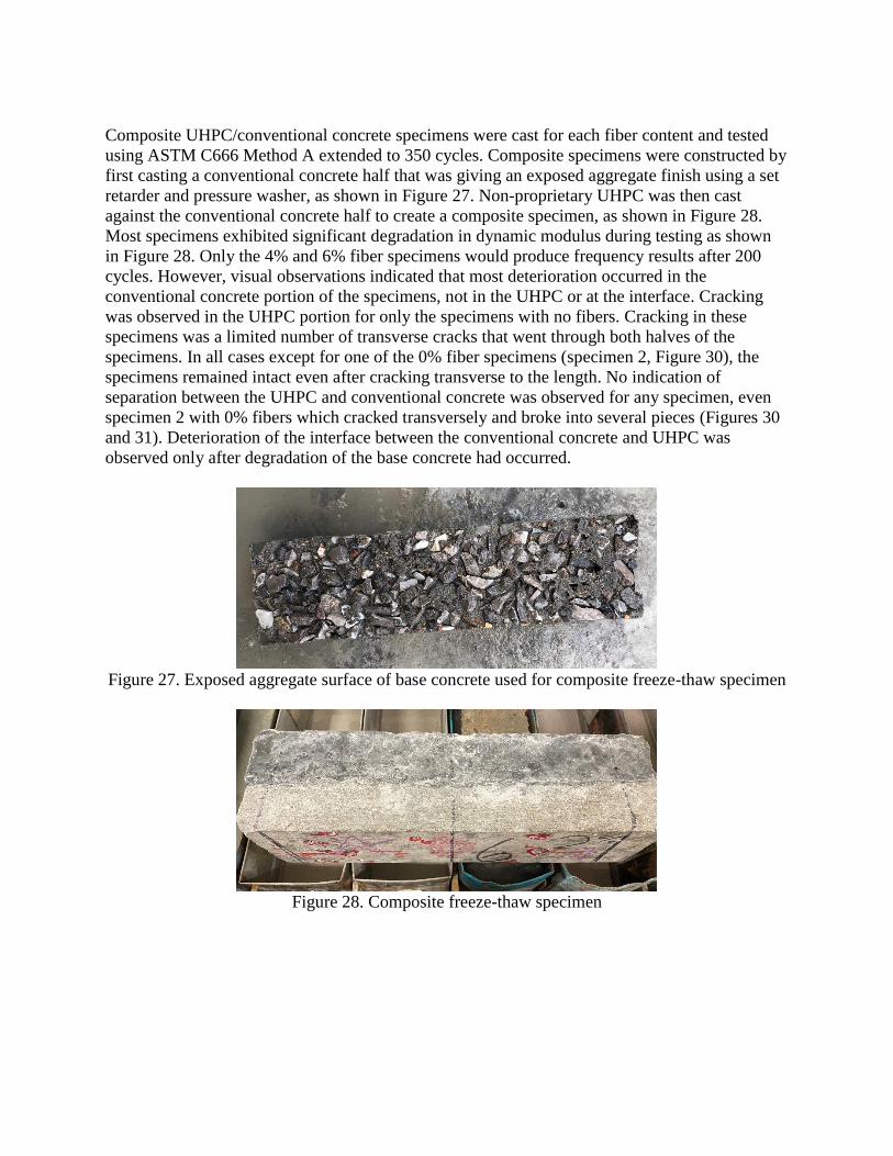
Composite UHPC/conventional concrete specimens were cast for each fiber content and tested
using ASTM C666 Method A extended to 350 cycles. Composite specimens were constructed by
first casting a conventional concrete half that was giving an exposed aggregate finish using a set
retarder and pressure washer, as shown in Figure 27. Non-proprietary UHPC was then cast
against the conventional concrete half to create a composite specimen, as shown in Figure 28.
Most specimens exhibited significant degradation in dynamic modulus during testing as shown
in Figure 28. Only the 4% and 6% fiber specimens would produce frequency results after 200
cycles. However, visual observations indicated that most deterioration occurred in the
conventional concrete portion of the specimens, not in the UHPC or at the interface. Cracking
was observed in the UHPC portion for only the specimens with no fibers. Cracking in these
specimens was a limited number of transverse cracks that went through both halves of the
specimens. In all cases except for one of the 0% fiber specimens (specimen 2, Figure 30), the
specimens remained intact even after cracking transverse to the length. No indication of
separation between the UHPC and conventional concrete was observed for any specimen, even
specimen 2 with 0% fibers which cracked transversely and broke into several pieces (Figures 30
and 31). Deterioration of the interface between the conventional concrete and UHPC was
observed only after degradation of the base concrete had occurred.
Figure 27. Exposed aggregate surface of base concrete used for composite freeze-thaw specimen
Figure 28. Composite freeze-thaw specimen

Figure 29. Results of freeze-thaw testing of the conventional concrete-UHPC interface
specimens
Figure 30. Splitting failure of composite freeze-thaw specimen with no steel fibers after 150
cycles (top) and after 350 cycles (bottom)
4000
4200
4400
4600
4800
5000
5200
5400
5600
5800
6000
0 24 68 106 149 196 241 276 310 359
Ave
rage
Fre
que
ncy (
Hz)
Number of freeze thaw cycles
1 (0%) 2 (0%) 3 (1%) 4 (1%) 5 (2%) 6 (2%) 7 (4%) 8 (4%) 9 (6%) 10 (6%)

Figure 31. UHPC-conventional concrete interface for failed specimen shown in Figure 24
Task 4- Short Course Development
Materials required for teaching a short course focused on development and use of non-
proprietary UHPC will be developed incorporating the results of the project. These materials will
include presentation slides, physical models and demonstrations, a plan for limited laboratory
testing, and assessment exercises. The PI will teach the course once near the end of the project,
but the materials will be designed such that it can be taught for DOTs and other stakeholders
after completion of the project as needed. A fee will be charged to participants to fund execution
of the short course.
An outline of the course topics was completed in conjunction with the development of the
content for the Technology Transfer Workshop described in Task 5. PowerPoint presentations
created for the Technology Transfer Workshop will be used to develop the short course. Short
course materials are being developed to be used as part of a series of future regional workshops
on non-proprietary UHPC presented by ABC-UTC. Input on the proposed outline and topics to
be included was solicited from the other project PIs during the project meeting on May 12, 2020
and additional discussion on the short course was held during a project meeting on October 9,
2020. Work has continued on refining the PowerPoint presentations to be used for the short
course and on identifying information on non-proprietary UHPC work completed by state DOTs.
Task 5- Technology Transfer Workshop
A technology transfer workshop will be held during the fourth-quarter of this study to share
performance of the “ABC-UTC Non-Proprietary UHPC Mix” with the ABC-UTC stakeholders.
It will be coordinated by OU, but will involve presentations by each partner institution. Financial
support for this workshop is included in the budget.
A two-part Technology Transfer Workshop was conducted at the 2019 International Accelerated
Bridge Construction Conference in December 2019. The workshop was split into two, four-hour
blocks. The morning session included presentations on the need for non-proprietary UHPC, mix
proportioning and material selection, material properties of the “ABC-UTC Non-Proprietary
UHPC mix”, durability properties of non-proprietary UHPC, structural performance of non-
proprietary UHPC, and effect of local materials on mixture performance.

The morning session presentations were made by representatives from three of the five ABC-
UTC partner institutions. Dr. Royce Floyd (OU) and Dr. Jeff Volz (OU) presented on material
selection, material properties, durability, and research on non-proprietary UHPC across the
country. Dr. Atorod Azizinamini (FIU) presented on UHPC applications and the need for non-
proprietary UHPC and Dr. David Garber (FIU) presented on the effects of regional materials on
UHPC mix performance. Dr. Mohamed Moustafa (UNR) presented on deck panel joint testing.
More than 50 people attended the morning workshop.
The afternoon session included an interactive mixing, testing, and placement demonstration at
the FIU materials laboratory where the attendees were able to see the non-proprietary UHPC
mixed and tested. Graduate student Trevor Looney (OU) and Dr. Royce Floyd led these sessions
with the support of Dr. David Garber, graduate student Esmail Shahrokhinasab (FIU), FIU
laboratory staff. A photo of the mixing and placement demonstration is shown in Figure 31.
Approximately 30 people attended the afternoon workshop. Attendees provided substantial
constructive and helpful feedback throughout the workshop sessions.
A workshop with very similar content is being planned for 2021 as part of an ODOT sponsored
project.
Figure 31. Placement of non-proprietary UHPC in demonstration formwork during the mixing
and placement demonstration workshop at FIU
Task 6- Assembling Reports and “Guide for ABC-UTC Non-Proprietary UHPC”
Quarterly progress reports and a final report in Microsoft Word and ADA accessible Adobe
Acrobat pdf will be provided at the end of the project year. In addition, recommendations and
guidance for development and splice length of reinforcing bars cast in UHPC for bridge

applications will be provided. A “Guide for ABC-UTC Non-Proprietary UHPC” will be
developed incorporating the results of research performed by all partner institutions and
described in individual proposals that will be submitted to ABC-UTC and prepared by partner
universities. The research team will work with the project Research Advisory Board to identify
next steps for implementation of non-proprietary UHPC and the Guide within state DOTs.
This report is the eighth for the project. Work on the final report and Guide is underway.
Expected completion for the final report is in March 2021.
5. Expected Results and Specific Deliverables
Quarterly progress reports and a final report in Microsoft Word and ADA accessible Adobe
Acrobat pdf will be provided at the end of the project. In addition, recommendations and
guidance for development and splice length of reinforcing bars cast in UHPC for bridge
applications will be provided. A synthesized summary of the ABC-UTC collaborative project
will be included in the final report and a “Guide for ABC-UTC Non-Proprietary UHPC” will be
developed incorporating the results of research performed by all partner institutions. This Guide
will include the recommended “ABC-UTC Non-Proprietary UHPC Mix”, recommendations for
adjusting the Mix for variations in local constituent materials, and recommendations for fiber
content necessary for specific applications.
6. Schedule Progress of tasks in this project is shown in the table below. Restrictions on on-site work at OU
due to the COVID-19 pandemic delayed completion of the last few laboratory items required for
this project until late 2020, but all lab work has been completed. Similar restrictions delayed
work at the other partner institutions. Work is nearing completion at all partner institutions.
Item % Completed
Percentage of Completion of this project to Date 98%
J F M A M J J A S O N D J F M A M J J A S O N D J F M A M
Work Performed
Work to be Performed
4. Short Course Development
5. Technology Transfer Workshop
6. Assemble Reports
2020Research Task 2019 2020
1. Comparative Mix Testing
2. UHPC-Rebar Bond Testing
3. UHPC Durability Testing

7. References
1- AASHTO (2014) AASHTO LRFD Bridge Design Specifications, 5th edition,
Washington, D.C.
2- ACI Committee 408 (2003) “Bond and Development of Straight Reinforcing Bars in
Tension (408R-03),” Technical Documents, American Concrete Institute, Farmington
Hills, MI.
3- ASTM Standard C39 (2016) “Standard Test Method for Compressive Strength of
Cylindrical Concrete Specimens,” ASTM International, West Conshohocken, PA.
4- ASTM Standard C78 (2015) “Standard Test Method for Flexural Strength of
Concrete (Using Simple Beam with Third-Point Loading),” ASTM International,
West Conshohocken, PA.
5- ASTM Standard C109 (2016) “Standard Test Method for Compressive Strength of
Hydraulic Cement Mortars (Using 2-in. or [50 mm] Cube Specimens,” ASTM
International, West Conshohocken, PA.
6- ASTM Standard C157 (2014) “Standard Test Method for Length Change of
Hardened Hydraulic-Cement Mortar and Concrete,” ASTM International, West
Conshohocken, PA.
7- ASTM Standard C469 (2014) “Standard Test Method for Static Modulus of Elasticity
and Poisson’s Ratio of Concrete in Compression,” ASTM International, West
Conshohocken, PA.
8- ASTM Standard C496 (2011) ‘Standard Test Method for Splitting Tensile Strength of
Cylindrical Concrete Specimens,” ASTM International, West Conshohocken, PA.
9- ASTM Standard C512 (2015) “Standard Test Method for Creep of Concrete in
Compression,” ASTM International, West Conshohocken, PA.
10- ASTM Standard C666 (2015) “Standard Test Method for Resistance of Concrete to
Rapid Freezing and Thawing,” ASTM International, West Conshohocken, PA.
11- ASTM Standard C672 (2012) “Scaling Resistance of Concrete Surfaces Exposed to
Deicing Chemicals,” ASTM International, West Conshohocken, PA.
12- ASTM Standard C1202 (2017) “Standard Test Method for Electrical Indication of
Concrete’s Ability to Resist Chloride Ion Penetration,” ASTM International, West
Conshohocken, PA.
13- ASTM Standard C1437 (2015) “Standard Test Method for Flow of Hydraulic Cement
Mortar,” ASTM International, West Conshohocken, PA.
14- ASTM Standard C1583 (2013) “Standard Test Method for Tensile Strength of
Concrete Surfaces and the Bond Strength or Tensile Strength of Concrete Repair and
Overlay Materials by Direct Tension (Pull-off Method), ASTM International, West
Conshohocken, PA.
15- ASTM Standard C1856 (2017) “Standard Practice for Fabricating and Testing
Specimens of Ultra-High Performance Concrete,” ASTM International, West
Conshohocken, PA.
16- Graybeal, B.A. and Baby, F. (2013) “Development of Direct Tension Test Method for
Ultra-High Performance Fiber-Reinforced Concrete,” ACI Materials Journal, 110(2):
117-186.

17- Haber, Z.B., De la Varga, I., Graybeal, B.A., Nakashoji, B., El-Helou, R. (2018)
“Properties and Behavior of UHPC-Class Materials,” FHWA-HRT-19-036, March
2018, 151 pp.
18- Ramirez, J.A. and Russell, B.W. (2008). Splice Length for Strand/Reinforcement in
High-Strength Concrete, NCHRP Project 12-60 Report, Transportation Research
Board, Washington, D.C.
19- RILEM (1994) “RC5: Bond Test for Reinforcing Steel. 1. Pullout test,” RILEM
Technical Recommendations for the Testing and Use of Construction Materials, 7-II-
128, E&FN Spon, London, U.K.…………………..