osm deployment and integration...osm white paper osm deployment and integration a white paper...
TRANSCRIPT
OSM White Paper
OSM Deployment and Integration
A White Paper prepared by the OSM End User Advisory Group
Issue 1
February 2020
ETSI 06921 Sophia Antipolis CEDEX, France Tel +33 4 92 94 42 00 [email protected] www.etsi.org
Deployment and Integration of OSM 2
Contents Contents 2
Authors 3
Summary 4
The Context of OSM and NFV Orchestration 6
Rapid Introduction of New Automated Services 6
Interworking Architecture 7
Standardization and Interfaces in existing BSS/OSS 9
TM Forum 9
MEF 9
Two Use Cases to Illustrate OSM Interworking 11
Business Services Use Case 11
Use case architecture and role of OSM 12
Northbound and East/West bound interactions 15
Matching of information model entities 16
Automated creation of APIs 18
Southbound interfacing with existing management systems 19
5G Network Slicing and MEC Use Case 20
Use case architecture 21
Support of Slicing, Orchestrated Domains, and Federation Between MNOs 22
Support of Proprietary ‘Orchestrated’ Domains 24
Conclusions 25
Deployment and Integration of OSM 3
Authors Editor:
Andy Reid, BT
Contributors:
Antonio Marsico, BT
Ahmed ElSawaf, STC
Gerardo García, Telefónica
Francisco Javier Ramón, Telefónica
Pål Grønsund, Telenor
Saad Sheikh, STC
Deployment and Integration of OSM 4
Summary
The recent development, and current deployment, of a number of technologies in communications service providers (CSPs) networks are making a step change in the levels of process automation. The range of processes where automation can be exploited is very broad and covers the full spectrum, from new service creation, to in-service and network monitoring. The critical enabler for these new levels of automation is a programmable network infrastructure. The growing deployment of network functions virtualisation infrastructure (NFV), along with software defined networking (SDN), provides the required level of programmability. While, in the past, the creation of new capabilities required the deployment of new physical boxes - a manual process - new capabilities can now be deployed by suitable programming of the NFVI/SDN infrastructure.
While the deployment of a programmable infrastructure is a necessary prerequisite for automation, it is not sufficient by itself. Automation can only be achieved if there are suitable software systems that can translate the comparatively simple initial intent of an operational process into the complex programming that is initial intent of an operational process into the complex programming that is needed in the network in order to achieve the initial intent.
The concept of a next generation of business and operational support systems (BSS/OSS) has been widely discussed in the industry with suitable architectures being developed in industry bodies such as the TeleManagement Forum (TMF) and the Metro Ethernet Forum (MEF). Orchestration plays a critical component of this next generation BSS/OSS (NG-BSS/OSS) and the functionality provided by OSM is a key component of this future world of highly automated processes.
However, the development of a completely new and comprehensive NG-BSS/OSS is a highly complex task, and achieving a seamless switchover from a CSP’s current BSS/OSS without interrupting service to end users is perhaps an even more complex task. As a result, for many CSP’s, strategy of progressive deployment of components of NG-BSS/OSS, and interworking them with components of their existing BSS/OSS is a more practical, lower risk, and quicker way of achieving the desired goal of a comprehensive NG-BSS/OSS. For these CSPs, a strategy of evolutionary interworking, rather than a revolutionary comprehensive change-out, is optimal.
OSM fully supports both models of introducing NG-BSS/OSS. As well as the key components of a complete NG-BSS/OSS, OSM can be introduced in an evolutionary way and interwork with existing BSS/OSS.
This paper illustrates how OSM can interwork with a CSP’s existing BSS/OSS and reap many of the process automation benefits by looking at the use case of business services. This use case shows how OSM can interface with existing BSS/OSS through its northbound interface (NBI), so that network services can be orchestrated and managed by OSM can be presented to the customer through an existing BSS and/or integrated with existing business services. In the latter case, the network service orchestrated and managed by OSM can be integrated as a component of a wider service, managed by the existing BSS/OSS. The OSM NBI is designed so that automated tooling, including the Swagger API toolkit and the YANG data modelling toolkit, can largely automate the creation of connectors between the OSM NBI and existing BSS/OSS. Furthermore, the OSM data
Deployment and Integration of OSM 5
model has an implicit abstraction that makes it compatible with the TM Forum SID information model, further assisting the rapid and straightforward creation of connectors.
This implicit abstraction in the OSM data model is also what has enabled the easy inclusion of different forms of network functions beyond virtual network functions (VNFs), notably physical network functions (PNFs) and containerised network functions (CNFs).
Southbound from OSM, OSM has supported from the outset a flexible plugin model which that enables OSM to integrate components which are managed and orchestrated in a wide range of ways. Integrating existing services and capabilities into network services orchestrated and managed by OSM can be readily achieved by adding suitable plugins to the OSM southbound modules (that is, the resource orchestrator (RO), the VNF configuration agent (VCA) and the monitoring module (MON)). All of these plugins are designed to facilitate southbound interworking.
This paper then addresses a second issue of the interworking that may reasonably arise in 5G networks and services, even when they are not burdened with legacy interworking. This is explored by examining the use case of 5G edge networking involving network slicing and multi-access edge computing (MEC), and the interconnection of these with large-scale core 5G VNFs, such as user plane function (UPF) and session management function (SMF). In this use case, orchestration and management does not naturally fall into a single flat layer, and number of layers of hierarchy naturally arise, even in a completely fresh deployment of 5G with exclusive NG-BSS/OSS. The paper shows that the interworking mechanisms that support interworking with existing BSS/OSS also support this layering and heterogeneous orchestration and management environments.
This second use case also illustrates a specific example of hybrid vitualisation with virtual machine based VNFs which themselves comprise containers which are independently orchestrated and managed from the virtual machines VNFs which host the containers.
The conclusion is that OSM provides a flexible platform that can be integrated into existing BSS/OSS, enabling rapid and low-risk automation integration to achieve full-service orchestration that can be exposed to customers exploiting NFV/SDN infrastructure. In addition, it is already showing the value of OSM’s basic architectural choices, as the new features that have emerged, after these choices were made, have been successfully added to OSM. These choices include network slicing, hierarchical network service in network service, CNFs, and heterogeneous network services which consists of PNFs, VNFs, CNFs, and/or cloud native network functions. This creates the confidence that OSM is flexible enough to incorporate other new features, as and when they emerge. At the same time OSM is a fully consistent component of a NG-BSS/OSS. OSM can, therefore, be introduced by a CSP in a way that matches their own current BSS/OSS strategy, and they can feel confident that it is also consistent with their plans for the future.
Deployment and Integration of OSM 6
The Context of OSM and NFV Orchestration
Rapid Introduction of New Automated Services Current communications service providers (CSPs) are undergoing a significant change in their infrastructures, on a journey to becoming digital service providers (DSP). New infrastructure is capable of supporting a new generation of services that underpin many of the developments in 5G, but it is also able to support existing services more cost-effectively. This transformation is not primarily about latest technology at each layer of the infrastructure. Rather it brings automation, openness, and agility to service creation and delivery, as well as allowing intelligent insights into customer and infrastructure behaviour. This transformation will also facilitate new business models and create new opportunities in the evolving value chain of services to end users.
The services ushered in by this wave of new and disruptive technologies is redefining the future shape of the telecoms industry. However, this change cannot have an immediate revolutionary impact on the telecoms industry due to the very nature of telecoms services that provide universal connectivity. This demands interworking with legacy services, infrastructure and systems in order to ensure customers can access these new services at a fast pace using the legacy connectivity they already have in place.
Over time, the old technology can be withdrawn and the interworking is no longer necessary. Only at this point will the ‘target’ architecture, free of legacy, be truly realised. This evolution can take many years, depending on market and use cases, and during this time the interworking is an essential ingredient of the overall architecture. The legacy services should still be available to customers, while the new services are introduced.
A simple example of this was the emergence of the Internet. The Internet emerged into a world where PSTN was the predominant technology. Interworking with PSTN in the form of ‘dial-up’ Internet access was critical to the emergence of the Internet as the ubiquitous global public network it is today. If we see the situation today, where the Internet has become a necessary constituent of life and society at large, one can say that the cost of all the dial-up modems could have been avoided and, in fact, was an unnecessary expense, as the ‘target’ architecture of broadband access does not require them. However, the advantage of early availability and the experience of Internet access using dial-up clearly overshadows any costs, in terms of both material and time required for this interworking.
The introduction of NFV, SDN and cloud infrastructures, fuelled by the idea that services can be delivered in a programmable manner exploiting automation and orchestration, has opened a new direction for the telecoms industry to redefine the future of business and network operational support systems (BSS/OSS), with orchestration as a critical component. Orchestration is vital to the ‘target’ architecture of a next generation BSS/OSS (NG-BSS/OSS). However, it is also fully anticipated that, for many operators, interworking with existing BSS/OSS will be a critical feature for a number of years. OSM fulfils the requirement for orchestration in the target architecture, but also provides for the essential interworking with existing systems in the period before the target architecture can be fully realised.
Deployment and Integration of OSM 7
In this white paper, we examine a number of points where such interworking is likely to be useful, and how OSM can be deployed and achieve the immediate benefits of automated service creation and deployment, without the need for the wholesale change-out of all a CSP’s existing BSS/OSS.
In short, OSM fulfils the requirement for orchestration in the target architecture, and also provides for the essential interworking with existing systems in the period before the target architecture can be fully realised. Importantly, with OSM, CSP’s do not need to wait to change out the rest of the BSS/OSS estate, before gaining the benefits of orchestration.
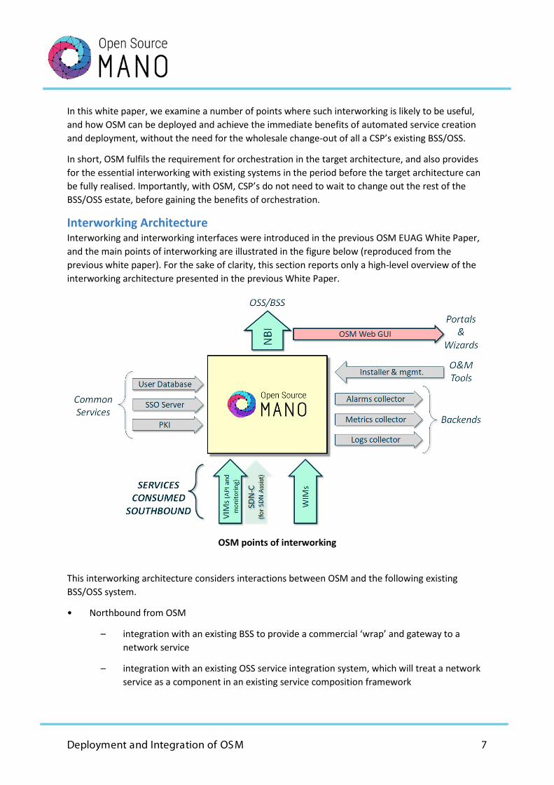
Interworking Architecture Interworking and interworking interfaces were introduced in the previous OSM EUAG White Paper, and the main points of interworking are illustrated in the figure below (reproduced from the previous white paper). For the sake of clarity, this section reports only a high-level overview of the interworking architecture presented in the previous White Paper.
OSM points of interworking
This interworking architecture considers interactions between OSM and the following existing BSS/OSS system.
• Northbound from OSM
– integration with an existing BSS to provide a commercial ‘wrap’ and gateway to a network service
– integration with an existing OSS service integration system, which will treat a network service as a component in an existing service composition framework
Deployment and Integration of OSM 8
• Southbound from OSM
– consumption of existing internal service components that can be treated as virtual links (in principle, this could be extended to treat an existing internal service as a form of network service)
• East/West from OSM
– integration with an existing inventory management system
– integration with an existing fault and performance management system
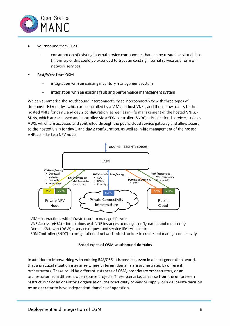
We can summarise the southbound interconnectivity as interconnectivity with three types of domains: - NFV nodes, which are controlled by a VIM and host VNFs, and then allow access to the hosted VNFs for day 1 and day 2 configuration, as well as in-life management of the hosted VNFs; - SDNs, which are accessed and controlled via a SDN controller (SNDC); - Public cloud services, such as AWS, which are accessed and controlled through the public cloud service gateway and allow access to the hosted VNFs for day 1 and day 2 configuration, as well as in-life management of the hosted VNFs, similar to a NFV node.
Broad types of OSM southbound domains
In addition to interworking with existing BSS/OSS, it is possible, even in a ‘next generation’ world, that a practical situation may arise where different domains are orchestrated by different orchestrators. These could be different instances of OSM, proprietary orchestrators, or an orchestrator from different open source projects. These scenarios can arise from the unforeseen restructuring of an operator’s organisation, the practicality of vendor supply, or a deliberate decision by an operator to have independent domains of operation.
Deployment and Integration of OSM 9
• Northbound from OSM
– providing a network service to a domain orchestrated by a different orchestrator
• Southbound from OSM
– consumption of a network service or a VNF from a domain orchestrated by a different orchestrator
Standardization and Interfaces in existing BSS/OSS TM Forum Establishing general characteristics of the existing BSS/OSS of operators is not straightforward, as operators tend to have a wide variety of systems from different generations of technology and have different mixes of solutions from vendors, customised solutions from vendors, and internally developed software.
The TM Forum, working with many operators and vendors, has developed a collection of architecture, interface, and information modelling documents, At a top and abstract level, the TM Forum framework provides a common vocabulary for operators and vendors to discuss a full range of business and operational processes, with associated systems, even where implementations may be very different.
• Also, at this top level, the TM Forum framework allows for a comparison between different operators’ BSS/OSS estates, and also between an operator’s estate and current best practice.
• At the next level, the TM Forum has specified interfaces and information models that are capable of being abstracted to a reasonably high degree. This means that conformance with a specification can be aligned with the broad semantics of the TM Forum specification, even if the details may be different. This can greatly reduce the amount of work needed to implement interworking between systems, as it means that there should be a common understanding of the broad methods being activated and the broad information being exchanged. Some coding may well be necessary to align the details of the interfaces.
Another key feature of the TM Forum’s working method is Catalyst projects. These collaborative projects between operators and vendors demonstrate something of interest to the BSS/OSS community, for example, automation of a key process, or interworking between a number of proprietary systems, using the TM Forum interface and/or information specifications.
In practice, many CSPs have used the TM Forum specifications as the starting point for interfaces within the OSS/BSS, and have added details according to the needs of their specific services and network infrastructures. This means that there are many different detailed implementations of the TM Forum interfaces, both by CSP directly, and by their OSS/BSS vendors. However, they all share the same basic features.
MEF Unlike TM Forum, MEF has historically set itself the objective of defining precise interfaces, with the aim of defining “MEF-compliant” services. Achieving this means that MEF-compliant services can then be consumed by a user in a common manner, irrespective of the CSP supplying the service.
Deployment and Integration of OSM 10
Central to the MEF process is, therefore, first defining a ‘necessary and sufficient’ (as discussed in the first OSM EUAG White Paper) interface specification that covers all the necessary aspects of the service, including data plane formats and performance, as well as the management and control plane, and, second, verifying conformance of the services with the MEF specification.
The scope of MEF specifications started with the essential specifications of carrier Ethernet services. This quickly advanced from the specification of data plane protocol/frame structures to include the technical quality of service parameters, and then to encompass a wide range of automated business-to-business (B2B) automated gateways. MEF has now has established a formal framework that explicitly layers the data plane aspects of service, the control and performance aspects of service, and the commercial aspects of service.
As a result of the availability of programmable NFV and SDN infrastructures, MEF has extended its scope well beyond the original carrier Ethernet services, and the scope of MEF defined services now includes SD-WAN, IP, Carrier Ethernet, Optical Transport, as well as more general applications supported by NFV. In addition, the security aspects of services are in the MEF scope.
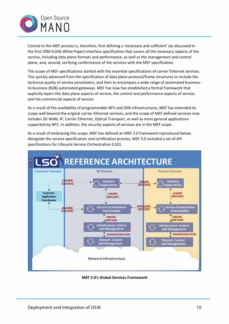
As a result of embracing this scope, MEF has defined an MEF 3.0 framework reproduced below. Alongside the service specification and certification process, MEF 3.0 included a set of API specifications for Lifecycle Service Orchestration (LSO).
MEF 3.0’s Global Services Framework
Deployment and Integration of OSM 11
Two Use Cases to Illustrate OSM Interworking In this white paper, we use two use cases to illustrate OSM interworking.
The first use case illustrates “interworking with legacy BSS/OSS for business services”. CSPs have provided business services for many years, and for most telecoms operators this is a major sector of their overall business. Over the years, both the business services themselves and the BSS/OSS that manage the services have continuously evolved. Business services have always been an example of evolutionary interworking and continue to be so. This use case is therefore informative, as the development of NFV/SDN-based business services is important for most CSPs in its own right, and in addition, it also provides a general illustration of how OSM supports legacy interworking beyond business services.
The second use case is “5G network slicing and multi-access edge computing (MEC)”. This use case is concerned with the inevitably heterogeneous nature of 5G networks and services, and legacy interworking is less relevant. The scope of 5G services will be very much wider than the current CSP services, which is likely to require a basic architecture of largely autonomous modular domains, and this will be particularly the case when the roaming of 5G services between mobile network operators (MNOs) is taken into account. This use case explores likely 5G architectures supporting slicing and MEC, and how OSM is sufficiently flexible for a wide variety of future possibilities.
Business Services Use Case
The services that CSPs supply to business already can be a mixture of connectivity services, customer premises equipment, and cloud services. NFV and SDN, when coupled with orchestration, give the opportunity for these services to be combined in a flexible and agile way, creating unified services covering all of these domains and more.
In a ‘greenfield’ scenario, the NFV, SDN and cloud components, along with the BSS/OSS, would all be new and compatible with an NG-BSS/OSS model. In this greenfield scenario, only new interfaces would be required, and no interworking with existing BSS/OSS would be necessary.
As noted in the introduction, while some industries can contemplate and achieve such a total generational change-out, this is rarely practical or cost-effective for services involving major telecoms components. When telecoms are involved, some level of interworking with existing systems is normally the fastest and most cost-effective way of achieving the services benefits for the customers.
The use case scenario is illustrated in the figure below. The specific example in the use case covers services to a global corporation that has sites around the world. The corporation needs both complex connectivity services between its sites, as well as the hosting of applications that may be in global data centres, regional/national data centres, or on a customer site. These sites can also host VNFs (or CNFs).

Deployment and Integration of OSM 12
Business Service Basic Architecture
Use case architecture and role of OSM If we were to contemplate a completely greenfield scenario, OSM would interface directly northbound to a customer gateway (BSS) system and directly southbound to the three types of infrastructure domains highlighted in the introduction, namely NFV nodes, SDN domains, and public cloud services.
Without any loss of generality, in this use case, we consider a specific example of an infrastructure comprising five domains:
• a customer premises domain with servers and switches sited on the customer premises, organised in a data centre architecture and managed by a virtual infrastructure manager (VIM) (i.e., the customer premises is arranged as an NFV node);
• a local WAN domain (an SDN domain) that provides connectivity between the customer premises and local nodes of the service provider (i.e., an SDN domain);
• a local datacentre (DC) domain that comprises local nodes of the service provider, which have a (normally private) data centre architecture with services and switches and are managed by a VIM (i.e., also arranged as an NFV Node);
• a global WAN domain that provides connectivity between local nodes and major data centre nodes (i.e., an SDN domain);
Deployment and Integration of OSM 13
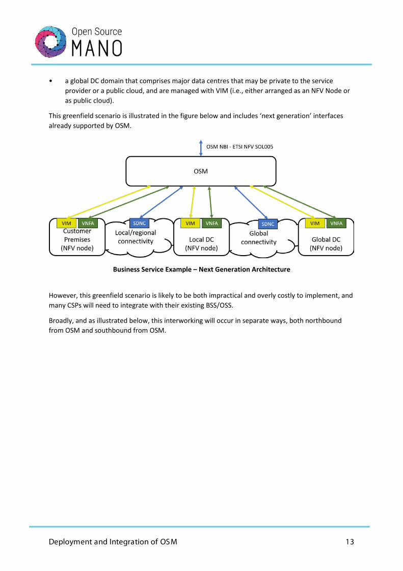
• a global DC domain that comprises major data centres that may be private to the service provider or a public cloud, and are managed with VIM (i.e., either arranged as an NFV Node or as public cloud).
This greenfield scenario is illustrated in the figure below and includes ‘next generation’ interfaces already supported by OSM.
Business Service Example – Next Generation Architecture
However, this greenfield scenario is likely to be both impractical and overly costly to implement, and many CSPs will need to integrate with their existing BSS/OSS.
Broadly, and as illustrated below, this interworking will occur in separate ways, both northbound from OSM and southbound from OSM.
Deployment and Integration of OSM 14
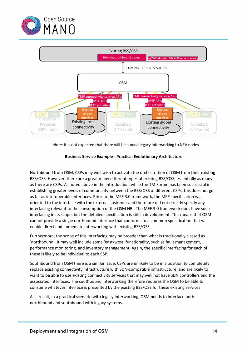
Business Service Example - Practical Evolutionary Architecture
Northbound from OSM, CSPs may well wish to activate the orchestration of OSM from their existing BSS/OSS. However, there are a great many different types of existing BSS/OSS, essentially as many as there are CSPs. As noted above in the introduction, while the TM Forum has been successful in establishing greater levels of commonality between the BSS/OSS of different CSPs, this does not go as far as interoperable interfaces. Prior to the MEF 3.0 framework, the MEF specification was oriented to the interface with the external customer and therefore did not directly specify any interfacing relevant to the consumption of the OSM NBI. The MEF 3.0 framework does have such interfacing in its scope, but the detailed specification is still in development. This means that OSM cannot provide a single northbound interface that conforms to a common specification that will enable direct and immediate interworking with existing BSS/OSS.
Furthermore, the scope of this interfacing may be broader than what is traditionally classed as ‘northbound’. It may well include some ‘east/west’ functionality, such as fault management, performance monitoring, and inventory management. Again, the specific interfacing for each of these is likely to be individual to each CSP.
Southbound from OSM there is a similar issue. CSPs are unlikely to be in a position to completely replace existing connectivity infrastructure with SDN-compatible infrastructure, and are likely to want to be able to use existing connectivity services that may well not have SDN controllers and the associated interfaces. The southbound interworking therefore requires the OSM to be able to consume whatever interface is presented by the existing BSS/OSS for these existing services.
As a result, in a practical scenario with legacy interworking, OSM needs to interface both northbound and southbound with legacy systems.
Deployment and Integration of OSM 15
Northbound and East/West bound interactions The OSM northbound interface presents all the controls allowed by OSM to the variety of OSM users. The OSM NBI is based directly on the ETSI NFV standards (SOL005), which were not specifically developed in the context of a wider BSS/OSS architecture. The context of the ETSI specification was more to simply expose the controls made available by orchestration, irrespective of the system (or person) that wishes to exercise the controls.
The OSM NBI follows this model, but it also allows these controls to be set in a role-based context. The role-based context, however, is oriented towards the security of the OSM system, both from inadvertent misconfiguration and also from malicious access. It is therefore only loosely based on the specific operations of a BSS/OSS, which in any case, are only loosely standardised, even if standards are followed.
It would therefore not be efficient for OSM to either assume one universal standard for northbound interworking of existing BSS/OSS, or to assume the burden of providing a bespoke NBI for every variant that may require interworking with OSM.
The effective interworking solution is for existing BSS/OSS to create a connector to interwork with the OSM NBI. Depending on the architecture, this could be a plugin to an existing system, or it could be a new intermediate ‘connector’ system that can translate between an existing internal set of appropriate APIs and the OSM NBI. The difference between these two (if indeed there is any material difference) will arise from the details of the architecture of the CSP’s existing BSS/OSS, and it would not be efficient or practical for OSM to make a judgement on this.
This arrangement would also cater for all East/West interworking as identified in the previous white paper, as all the OSM functionality is available through the OSM NBI. This interworking gateway is illustrated in the figure below.
Deployment and Integration of OSM 16
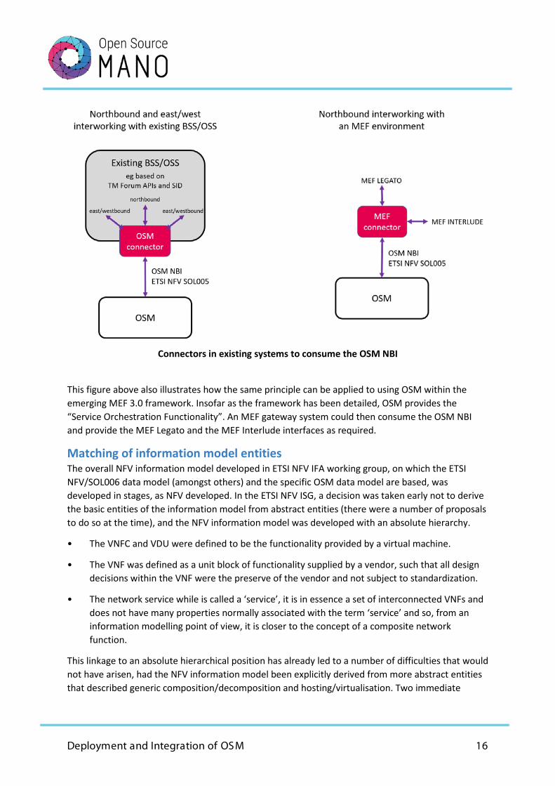
Connectors in existing systems to consume the OSM NBI
This figure above also illustrates how the same principle can be applied to using OSM within the emerging MEF 3.0 framework. Insofar as the framework has been detailed, OSM provides the “Service Orchestration Functionality”. An MEF gateway system could then consume the OSM NBI and provide the MEF Legato and the MEF Interlude interfaces as required.
Matching of information model entities The overall NFV information model developed in ETSI NFV IFA working group, on which the ETSI NFV/SOL006 data model (amongst others) and the specific OSM data model are based, was developed in stages, as NFV developed. In the ETSI NFV ISG, a decision was taken early not to derive the basic entities of the information model from abstract entities (there were a number of proposals to do so at the time), and the NFV information model was developed with an absolute hierarchy.
• The VNFC and VDU were defined to be the functionality provided by a virtual machine.
• The VNF was defined as a unit block of functionality supplied by a vendor, such that all design decisions within the VNF were the preserve of the vendor and not subject to standardization.
• The network service while is called a ‘service’, it is in essence a set of interconnected VNFs and does not have many properties normally associated with the term ‘service’ and so, from an information modelling point of view, it is closer to the concept of a composite network function.
This linkage to an absolute hierarchical position has already led to a number of difficulties that would not have arisen, had the NFV information model been explicitly derived from more abstract entities that described generic composition/decomposition and hosting/virtualisation. Two immediate
Deployment and Integration of OSM 17
examples are the introduction of containers (which does not fit in with the original NFV definition of the VNFC and VDU), and the recursive construction of a network service within a network service (as highlighted in the first OSM EUAG white paper). A further difficultly may arise when a VNF is not provided by a vendor but, for example, by an open source project, and, in this case, there is no clear delineation of the difference between an NS, a VNF and a VNFC.
As set out in the first OSM EUAG white paper, the choices OSM took from the options set out in the NFV MANO architecture already bring about considerable simplification and avoid some of these difficulties. Notably, the OSM data model has made the inclusion of new virtualised entities straightforward, and the decision to avoid the ‘granting’ model of resource assignment control avoids the problem of an orchestrator and a proprietary VNFM duplicate, and the fight over the same resource control function. OSM supports:
• resource control by OSM for entities orchestrated by OSM;
• the domain interface, as recommended by the first OSM EUAG white paper.
These two mechanisms support a full range of integration models but are also consistent with a simple underlying abstract model of composable/decomposable virtual functions. In essence, OSM implicitly created the abstract entities absent from the NFV standards, even if they were not explicitly documented. As a result, OSM has been able to introduce Network Slices, Network Service in Network Service, Physical Network Functions and Containerised Network Functions in a simple and straightforward manner.
Unlike the NFV information model, but in common with the OSM information model, the TM Forum SID information model does have a basic abstract model that describes composition/decomposition. This means that any existing system that has an information model based on the TM Forum SID can be readily mapped to the OSM information model. Had OSM not made the architectural choices it did, such a mapping between the OSM information model and the TM Forum information model would not be so straightforward.
As the TM forum SID has abstract entities, the VNFC, VNF, NS, and Network Slice can all be mapped to the same abstract class, and then each treated as sub-classes of this abstract class. This resolves the two difficulties already noted. When a VNF is built from containers rather than virtual machines, the function provided by the container is simply represented in the information model as an instance of a different sub-class to represent any necessary features arising from the containerisation, but this will still share all the same essential properties of the abstract super-class.
There are two possible candidate abstract classes within the SID that could be considered: a) the resource function, or b) the resource service.
At this stage, there could be a case of either, depending on the details of the information model of the existing system. However, given that OSM does not attempt to present any features associated with any commercial service wrap, it is likely that the resource function is the appropriate abstract entity from the TM Forum SID to map the VNFC, VNF, NS and Network Slice.
Having made this fundamental information model alignment, other entities such as descriptors and packages, follow in a straightforward manner.
Deployment and Integration of OSM 18
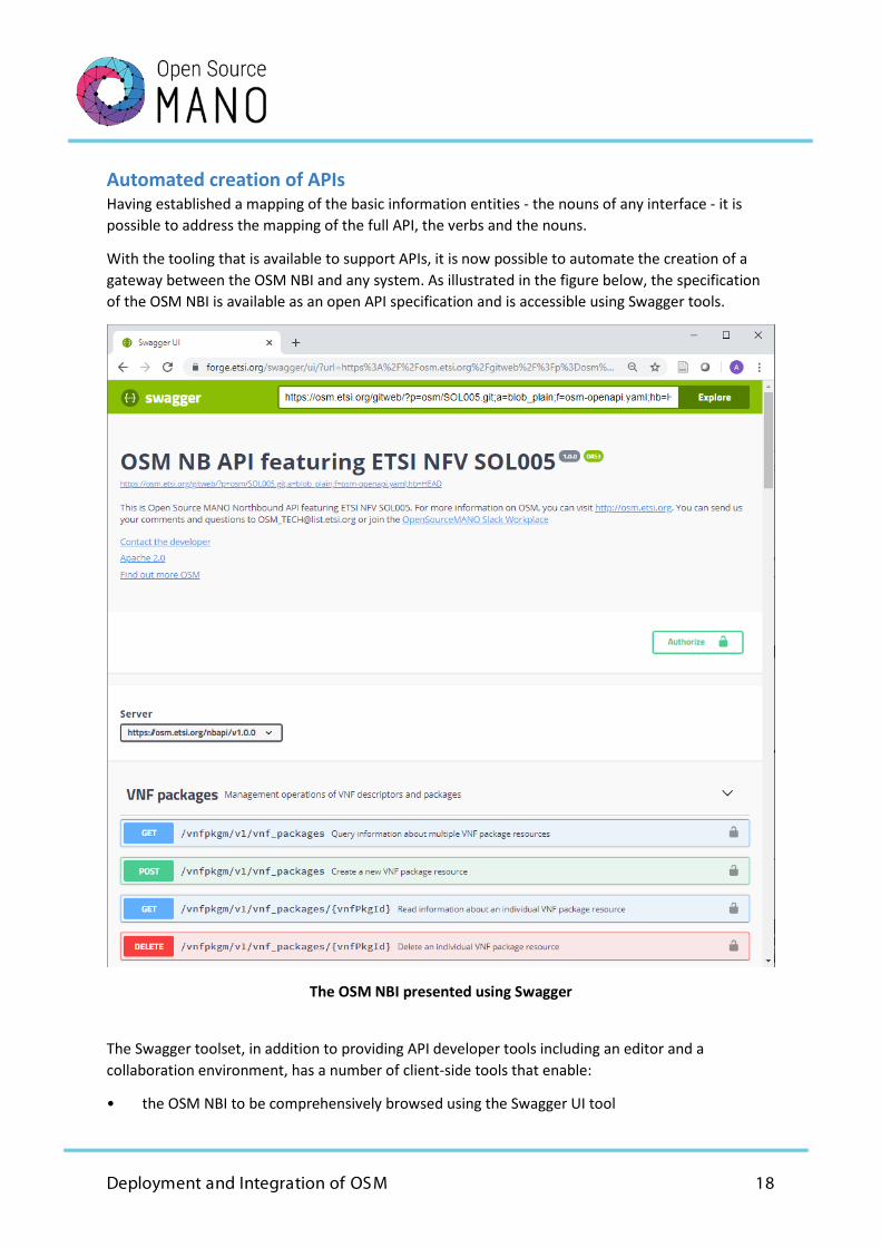
Automated creation of APIs Having established a mapping of the basic information entities - the nouns of any interface - it is possible to address the mapping of the full API, the verbs and the nouns.
With the tooling that is available to support APIs, it is now possible to automate the creation of a gateway between the OSM NBI and any system. As illustrated in the figure below, the specification of the OSM NBI is available as an open API specification and is accessible using Swagger tools.
The OSM NBI presented using Swagger
The Swagger toolset, in addition to providing API developer tools including an editor and a collaboration environment, has a number of client-side tools that enable:
• the OSM NBI to be comprehensively browsed using the Swagger UI tool
Deployment and Integration of OSM 19
• automatic generation of code for a wide variety of environments that will access the OSM NBI using the Swagger Codegen tool
The Codegen tool can simplify the integration of OSM in different OSS/BSS systems, since the definition of its APIs can be compiled for different programming languages. For instance, the implementation of an OSM connector for an OSS/BSS system can rely on the code generated by this tool.
In addition, there are similar YANG automation tools for generating connector code related to the data model, notably pyang and pyangbind, which generate the appropriate Python code.
When taken together, the combination of a) the alignment of fundamental entities between the OSM information model and the TM Forum SID model, b) the Swagger automated tooling, and c) the YANG automated tooling, the generation of a specific connector to meet the needs of a particular CSP’s interworking requirement should be a straightforward task.
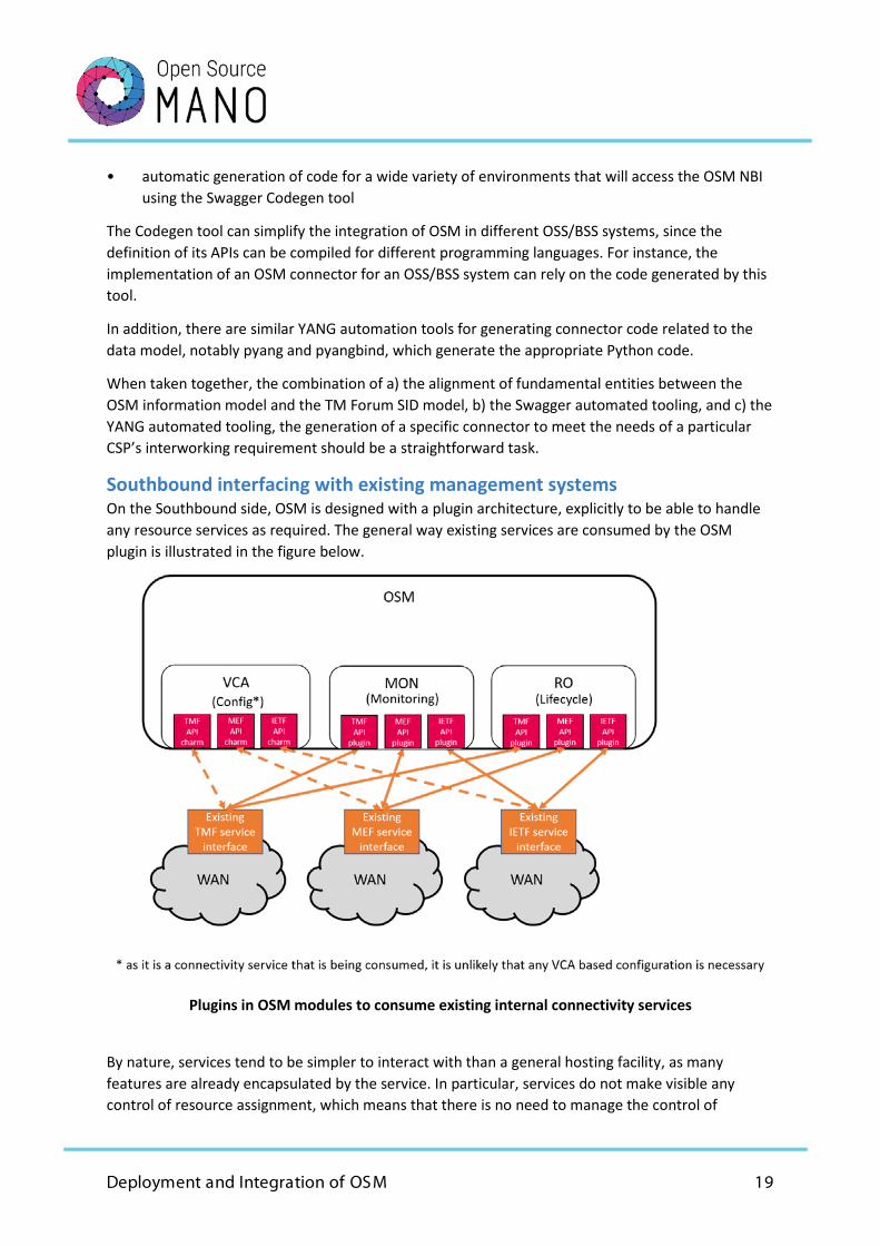
Southbound interfacing with existing management systems On the Southbound side, OSM is designed with a plugin architecture, explicitly to be able to handle any resource services as required. The general way existing services are consumed by the OSM plugin is illustrated in the figure below.
Plugins in OSM modules to consume existing internal connectivity services
By nature, services tend to be simpler to interact with than a general hosting facility, as many features are already encapsulated by the service. In particular, services do not make visible any control of resource assignment, which means that there is no need to manage the control of
Deployment and Integration of OSM 20
resource assignment. In addition, many services have minimal configuration requirements, if any, as the configuration is implicit in the service definition.
While in-life monitoring of a service instance is shown in the figure as being consumed by the OSM MON module, there many be circumstances where some monitoring might be more efficiently implemented through the VCA module or the RO module. This would be determined by the nature of the monitoring parameter and/or the way it is presented by the service API.
5G Network Slicing and MEC Use Case
Within 5G, there has been much discussion on the slicing feature of the 5G architecture and the use of multi-access-edge computing (MEC) capabilities. While the earliest deployments of 5G may be focussed on delivering higher mobile broadband speeds, most mobile operators are expecting to develop 5G applications that go well beyond the scope of mobile broadband.
Importantly, there are some prospective 5G applications that cannot be efficiently supported by the current ‘over-the-top’ model, where the mobile network provides only end-to-end connectivity between the end user’s end device (e.g., a smartphone) and an application server, normally hosted somewhere in a central data centre. GSMA, based on the analysis of a number of likely 5G applications, has been investigating the properties of the edge of the network (i.e., the radio access network, associated backhaul, and edge computing) that are required to support these applications.
As a result, GSMA has defined a generic slice template (GST) that contains the appropriate parameters which can be used to differentiate different slice types. In addition, GSMA has also defined three initial slice types.
• enhanced mobile broadband (eMBB): a slice type to support mobile broadband of a higher capacity than that supported by 4G and oriented to the over-the-top application model.
• ultra-reliable, low-latency connectivity (URLLC): a slice type to support interactive applications that are likely to have edge-computing functionality in addition to any data centre-based functionality.
• mobile Internet of things (mIoT): a slice type to support low-capacity messaging from and to IoT devices.
These slice types form an initial set that may be augmented in the future. They can also be refined and/or further specialised for the more specific needs of a mobile operator. These slice types are largely mirrored by the use of MEC to support local, low-latency application processing, especially for URLLC and mIoT applications.
Another important application of slicing that has been identified by GSMA is the support of roaming between mobile operators. This would allow a mobile operator to extend a 5G application beyond their own network by requesting a slice on a roamed network with the appropriate performance characteristics for that application. Coupled to this, GSMA is in the initial stages of defining the
Deployment and Integration of OSM 21
interconnection and federation of MEC facilities across MNOs to support fully roamed 5G applications.
Use case architecture As with the business services use case, this use case involves significant interworking. In this use case, much of the interworking arises from the need to interconnect domains that are separately administered, even when all these domains might be considered current or future, rather than existing or legacy. The need for interworking and integration arises from the complexity of the overall 5G system, and also from the fact that interworking is needed between different mobile operators.
Clearly, interworking may arise with existing systems as well. However, the focus of this use case is to illustrate how OSM can be integrated into the emerging world required to support 5G applications. Nonetheless, a common requirement in this use case with the interworking with existing systems, as illustrated by the business services use case, is the support of a layered service model. A layered service model allows for different component systems from different domains and with different development and support arrangements to be flexibly integrated.
The use case is set out as a series of architectural developments that follow some of the recent developments in 5G including network slicing, multi-access-edge computing (MEC) and containerised network functions (CNFs).
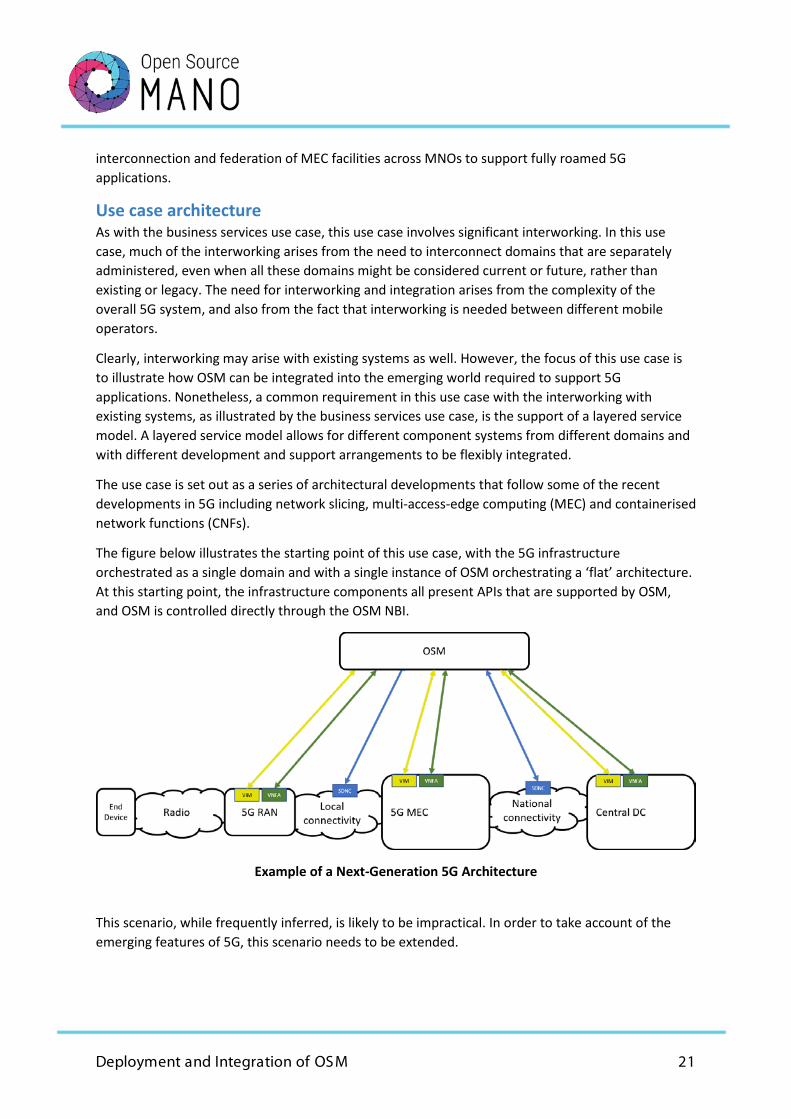
The figure below illustrates the starting point of this use case, with the 5G infrastructure orchestrated as a single domain and with a single instance of OSM orchestrating a ‘flat’ architecture. At this starting point, the infrastructure components all present APIs that are supported by OSM, and OSM is controlled directly through the OSM NBI.
Example of a Next-Generation 5G Architecture
This scenario, while frequently inferred, is likely to be impractical. In order to take account of the emerging features of 5G, this scenario needs to be extended.
Deployment and Integration of OSM 22
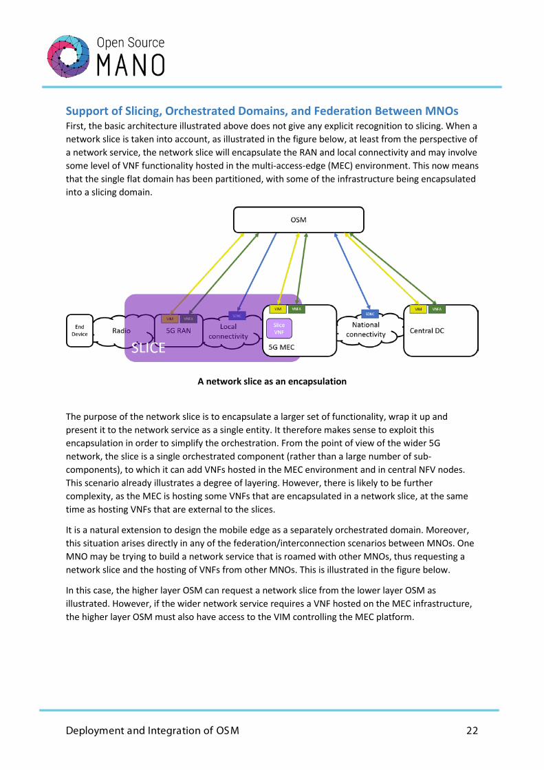
Support of Slicing, Orchestrated Domains, and Federation Between MNOs First, the basic architecture illustrated above does not give any explicit recognition to slicing. When a network slice is taken into account, as illustrated in the figure below, at least from the perspective of a network service, the network slice will encapsulate the RAN and local connectivity and may involve some level of VNF functionality hosted in the multi-access-edge (MEC) environment. This now means that the single flat domain has been partitioned, with some of the infrastructure being encapsulated into a slicing domain.
A network slice as an encapsulation
The purpose of the network slice is to encapsulate a larger set of functionality, wrap it up and present it to the network service as a single entity. It therefore makes sense to exploit this encapsulation in order to simplify the orchestration. From the point of view of the wider 5G network, the slice is a single orchestrated component (rather than a large number of sub-components), to which it can add VNFs hosted in the MEC environment and in central NFV nodes. This scenario already illustrates a degree of layering. However, there is likely to be further complexity, as the MEC is hosting some VNFs that are encapsulated in a network slice, at the same time as hosting VNFs that are external to the slices.
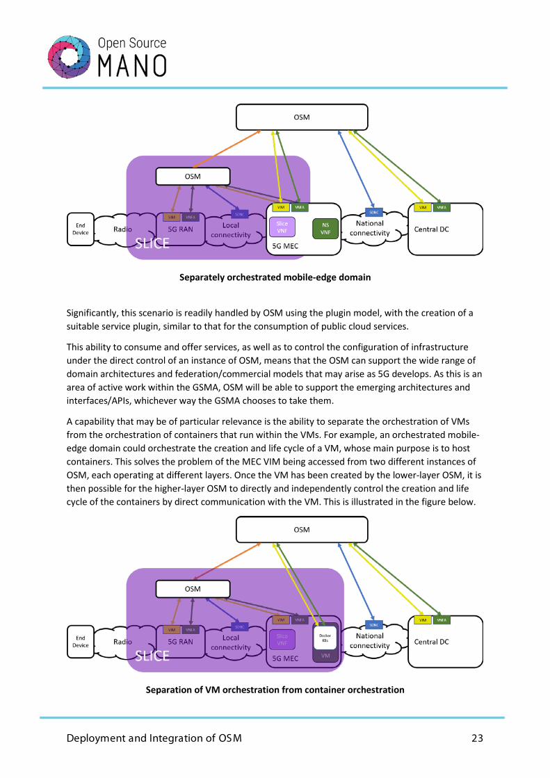
It is a natural extension to design the mobile edge as a separately orchestrated domain. Moreover, this situation arises directly in any of the federation/interconnection scenarios between MNOs. One MNO may be trying to build a network service that is roamed with other MNOs, thus requesting a network slice and the hosting of VNFs from other MNOs. This is illustrated in the figure below.
In this case, the higher layer OSM can request a network slice from the lower layer OSM as illustrated. However, if the wider network service requires a VNF hosted on the MEC infrastructure, the higher layer OSM must also have access to the VIM controlling the MEC platform.
Deployment and Integration of OSM 23
Separately orchestrated mobile-edge domain
Significantly, this scenario is readily handled by OSM using the plugin model, with the creation of a suitable service plugin, similar to that for the consumption of public cloud services.
This ability to consume and offer services, as well as to control the configuration of infrastructure under the direct control of an instance of OSM, means that the OSM can support the wide range of domain architectures and federation/commercial models that may arise as 5G develops. As this is an area of active work within the GSMA, OSM will be able to support the emerging architectures and interfaces/APIs, whichever way the GSMA chooses to take them.
A capability that may be of particular relevance is the ability to separate the orchestration of VMs from the orchestration of containers that run within the VMs. For example, an orchestrated mobile-edge domain could orchestrate the creation and life cycle of a VM, whose main purpose is to host containers. This solves the problem of the MEC VIM being accessed from two different instances of OSM, each operating at different layers. Once the VM has been created by the lower-layer OSM, it is then possible for the higher-layer OSM to directly and independently control the creation and life cycle of the containers by direct communication with the VM. This is illustrated in the figure below.
Separation of VM orchestration from container orchestration
Deployment and Integration of OSM 24
Support of Proprietary ‘Orchestrated’ Domains As a separate issue, some mobile operators may need to integrate into a domain orchestrated by OSM, a large and complex VNF, which comes bundled with extensive functionality to control its scaling and its resource assignment. The vendor may present its functionality as a VNF, and the control API from a proprietary VNFM, which would be consistent with the NFV definition of a VNF. In practice however, the proprietary VNFM is likely to have a large functional overlap with orchestration, especially in the control of scaling and resource management. This led ETSI NFV to develop complex functionality on the NFVO-VNFM reference point to manage this conflicting overlap, such that both sides still think they are in control of resources and scaling through complex protocols of grant requests and grants.
This was discussed in the first OSM EUAG white paper, and that paper concluded that an alternative and better solution, that avoids the competing will to control the details of scaling and resource management, is to treat the VNFM as an orchestrator accepting the control scaling and resource assignment. The network service-level orchestrator can then consume the VNF as a service that encapsulates the scaling and resource assignment. This model also conforms directly with the layered model of the TM Forum SID, as discussed in the business services use case.
In effect, OSM can treat the large VNF as the service of a separately orchestrated domain. When it is treated in this way, it becomes another example of the same architectural feature of layered orchestrated domains that supports the slicing and roaming described above, and the legacy interworking described in the business services use case. It is no longer a special case and the complex granting protocol is redundant.
Another way of describing this architecture is by broadening the concept of ‘resources’ in NFV to ‘functional resources’, as used by the TM Forum in the SID model. In NFV, resources are narrowly defined as virtual machines (and virtual links between them), so resource management is also narrowly defined as managing the resources assigned to virtual machines. Broadening the definition allows the VNFs themselves to be regarded as resources. Therefore, network service orchestration can request a VNF as a service from resource orchestration, which can be passed to a plugin that manages the interface with the domain manager (an orchestrator), which can provide that VNF as a service.
This also implies that OSM can use Juju to configure the VNF, without the need for an additional plugin. An OSM charm can interact with whatever the proprietary domain uses to control the VNF configuration, be it the VNF itself, an element manager (EM) or the proprietary VNFM, and take different types of actions. For instance, if a mobile operator wants to rely on the VNFM for monitoring, this could be achieved by means of Juju Metrics. Juju can retrieve the metrics from the VNFM APIs and use them as input for the OSM MON module.
This exact same model holds true for physical network functions (PNFs). These also, by definition, control there own scaling and resource assignment, but nonetheless can be configured, and the configuration can be controlled by an OSM Juju charm.
This illustrates that there are many ways of describing what is essentially the same basic model - that of layered, independently orchestrated domains. In each case, however, the same simple
Deployment and Integration of OSM 25
mechanism gives a flexible, yet comprehensive and reliable solution. In this case, the same basic model resolves the need for the complex granting model and validates the original OSM design decision to use the generic VNFM model and to avoid granting.
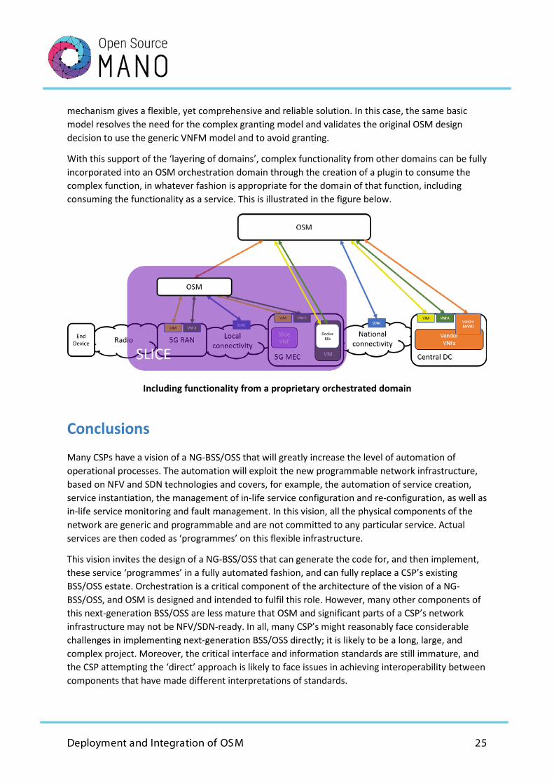
With this support of the ‘layering of domains’, complex functionality from other domains can be fully incorporated into an OSM orchestration domain through the creation of a plugin to consume the complex function, in whatever fashion is appropriate for the domain of that function, including consuming the functionality as a service. This is illustrated in the figure below.
Including functionality from a proprietary orchestrated domain
Conclusions
Many CSPs have a vision of a NG-BSS/OSS that will greatly increase the level of automation of operational processes. The automation will exploit the new programmable network infrastructure, based on NFV and SDN technologies and covers, for example, the automation of service creation, service instantiation, the management of in-life service configuration and re-configuration, as well as in-life service monitoring and fault management. In this vision, all the physical components of the network are generic and programmable and are not committed to any particular service. Actual services are then coded as ‘programmes’ on this flexible infrastructure.
This vision invites the design of a NG-BSS/OSS that can generate the code for, and then implement, these service ‘programmes’ in a fully automated fashion, and can fully replace a CSP’s existing BSS/OSS estate. Orchestration is a critical component of the architecture of the vision of a NG-BSS/OSS, and OSM is designed and intended to fulfil this role. However, many other components of this next-generation BSS/OSS are less mature that OSM and significant parts of a CSP’s network infrastructure may not be NFV/SDN-ready. In all, many CSP’s might reasonably face considerable challenges in implementing next-generation BSS/OSS directly; it is likely to be a long, large, and complex project. Moreover, the critical interface and information standards are still immature, and the CSP attempting the ‘direct’ approach is likely to face issues in achieving interoperability between components that have made different interpretations of standards.
Deployment and Integration of OSM 26
Conversely, many CSPs have an opportunity to move towards this vision of a next-generation BSS/OSS in agile, measured, and low-risk stages, or in evolutionary steps. This is facilitated by the architecture and design of OSM, which allow Northbound connectors to be developed using the OSM NBI and a suite of API-generation tools, including the Swagger API toolkit and YANG data modelling tools. In addition, as the OSM data model is based on an implicit superclass ‘network function’, of which the VNF, PNF, CNF, network service and network slice are all subclasses, this produces close alignment with the TM Forum SID information model, and notably, its ‘resource function’. This greatly simplifies matching the OSM data model with any model based on the TM Forum SID model.
Significantly, OSM now supports containerised network functions (CNFs). The introduction of this support also illustrates the flexibility of OSM and the value of its original architectural choices. OSM is not just able to orchestrate and manage CNFs, it is also able to treat VNFs based on virtual machines and CNFs independently, even to the extent that the VMs can be managed by one instance of OSM and the CNFs by another instance of OSM, a scenario that is made plausible by the GSMA proposals for slicing.
In this white paper, we have described two use cases where OSM orchestration can be introduced in a flexible way and that can interwork with existing BSS/OSS components, as well as making use of existing network infrastructure that is not NFV/SDN-compatible. Nonetheless, all the critical automation from NFV/SDN orchestration can be achieved, and achieved rapidly with much lower overall project risks. While these use cases describe important and useful situations that many CSPs will encounter, they are also illustrative of how many scenarios specific to an individual CSP can be resolved.

ETSI 06921 Sophia Antipolis CEDEX, France Tel +33 4 92 94 42 00 [email protected] www.etsi.org
This White Paper is issued for information only. It does not constitute an official or agreed position of ETSI, nor of its Members. The views expressed are entirely those of the author(s). ETSI declines all res pons ibility for any errors and any los s or damage res ulting from us e of the contents of this White Paper. ETSI als o declines res pons ibility for any infringement of any third party's Intellectual Property Rights (IPR), but will be pleas ed to acknowledge any IPR and correct any infringement of which it is advis ed. Copyright Notification Copying or reproduction in whole is permitted if the copy is complete and unchanged (including this copyright s tatement).
© European Telecommunications Standards Ins titute 2019. All rights res erved. DECT™, PLUGTESTS™, UMTS™, T IPHON™, IMS™, INTEROPOLIS™, FORAPOLIS™, and the T IPHON and ETSI logos are Trade Marks of ETSI, regis tered for the benefit of its Members . 7GPP™ and LTE™ are Trade Marks of ETSI, regis tered for the benefit of its Members and of the 3GPP Organizational P artners . GSM™, the Global Sys tem for Mobile communication, is a regis tered Trade Mark of the GSM As s ociation.