orthographic drawing - style design · pdf fileability to draw plans, ... dimension lines...
TRANSCRIPT
Orthographic Drawing ID1-DFD-OD
Dimension Styles
Ability to draw plans, sections and elevations
Produce schedules
Accuracy and Neatness of final work
Ability to plan a space and communicate ideas through drawings
Module notes and exercises
During the course of the tutorial there are exercises that you will encounter. Each one of these exercises need to be completed before you move onto the next section of work. At the end of each section there will be a cumulative assignment which uses all you new skills to complete. You will need to: * Draw basic a full set of drawings for an internal space. * Fully dimension your own drawings *Present your drawings as per layout learnt in Module 1 *Understand the importance of scheduling within a project. *Fully annotate your drawings
This module continues to teach you the standards involved in architectural drafting as well as introducing you to the main drawings involved in drawing being: Plans, sections, elevations and detailed drawings. The module also shows you the different types of dimensioning available as well as basic dimensioning standards. The module also introduces you to the concept of door, window and finishing schedules.

ID1-DFD-OD
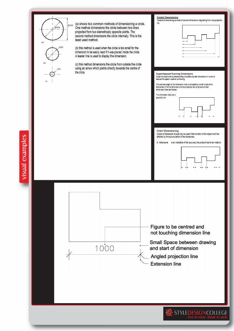
Dimensioned Drawings: All technical drawings need to be dimensioned, meaning that all measurements and sizes of objects, spaces or elements are written on the drawing. This ensures that accurate details to the viewer or manufacturer are conveyed. Horizontal dimensions are always shown on plan and vertical dimensions (heights) are always shown on elevations or sections. Dimensions should never crowd a drawing, and if you require 2 rows of dimensions they must be about 8 – 10mm apart for ease of reading. The overall size of an object should always be the outermost dimension, major elements next and smaller elements closest to the drawing. Dimensions should be drawn with a 0.18mm pen Dimensions are always drawn using continuous thin lines. Dimension lines continue past the outlines and projection lines of the drawing being dimensioned. Intersecting lines extend perpendicular towards the drawing and overlap the dimension line slightly. The two perpendicular projection lines indicate where the dimension starts and finishes. The points of intersection of dimension lines are emphasised by either a small dot or a 45 degree diagonal stroke. Pen sizes for this stroke are 0.5mm pen. Dimension figures are placed immediately above the corresponding horizontal dimension line. On vertical dimensioning they are placed to the left hand side reading upwards. In addition, they should be placed centrally between each intersection marker. Dimension figures should be neatly printed and about 2-3mm in height. These figures must not touch the dimension line. Two pencil guide lines must be ruled for accurate and constant heights to be achieved. Figures should be written in 0.35mm pen. In general units can be omitted from dimensions if a statement of the units is included on your drawing. The general convention is to dimension in millimetres (mm's). The dimension must reflect the true measurement of the object, regardless of the scale of drawing. Dimensions less than 1 should have a leading zero, for example .35 should be written as 0.35. A dimension tolerance is an indication of the accuracy the product has to be made to. It is not possible in practice to manufacture products to the exact figures displayed on a drawing. The accuracy depends largely on the manufacturing process used and the care taken to manufacture a product. A tolerance value shows the manufacturing department the maximum permissible variation from the dimension. Each dimension on a drawing must include a tolerance value.
Interior Design Visual Presentation, Maureen Mitton
Foundations of Interior Design, Susan J. Slotkis
Mastering Perspective, Santiago Arcas
Perspective for Interior Designers, John Pile
Architectural Drafting for Interior Designers, Lydia Cline
ID1-DFD-OD
This can appear either as: * a general tolerance value applicable to several dimensions, for example a note specifying that the General Tolerance +/0.5mm). * A tolerance specific to that dimension There are different types of dimenisoning that one can make use of in a drawing. They are detailed as follows: Parallel Dimensions: Parallel dimensioning consists of several dimensions originating from one projection line. Superimposed Running Dimensions: Superimposed running dimensioning simplifies parallel dimensions in order to reduce the space used on a drawing. The common origin for the dimension lines is indicated by a small circle at the intersection of the first dimension and the projection line. In general all other dimension lines are broken. Chain Dimensioning: Chains of dimension should only be used if the function of the object won't be affected by the accumulation of the tolerances. Dimensioning circles: There are several conventions used for dimensioning circles: *Dimensioning a circle externally: This method dimensions the circle between two lines projected from two diametrically opposite points. *Dimensioning a circle internally: This method is used when the circle is too small for the dimension to be easily read if it was placed inside the circle. A leader line is used to display the dimension: * This method dimensions the circle from outside the circle using an arrow which points directly towards the centre of the circle.

ID1-DFD-OD
Orthographic Drawings: As a designer you will need the manufacturer to understand exactly how to read your drawing. A full set of drawings comprise of: A plan Elevations Sections Details Floor Plans: A floor plan is an aerial plan view that is horizontally cut approximately1200mm above floor height. It is considered the most important architectural drawing that presents significant amount of information on the design and construction. It includes wall, door, window, stair, appliance, equipment, cabinetry, and built-in interior elements. A floor plan is drawn to a suitable scale with different line weights and line types to deliver different levels of information clearly. For instance, dotted/hidden lines are used to indicate the items that are located above the cutting line such as upper cabinets, upper part of stairway, openings, soffits, or other important upper part of the wall or ceiling features. Ceiling changes can be denoted with dashed lines called out for notes in a small project. Cross referencing symbols are used to relate the information on the floor plan to other drawings such as elevation, section, and detail drawings. You will need to include the following information on all Floor Plans which you produce: *Title Panel * Title and scale of the drawing in the title block. * Arrow indicating where North is. * Exterior walls and interior walls. * Outline of external areas such as, patios etc. * All Windows * All Doors *Wall openings, arches, and soffits with dotted/hidden lines. *Directional arrows for stairs *Room labels *All Bathroom fixtures *All appliances *Any built in fittings *Dimensions *Notations

ID1-DFD-OD
Interior Elevation Views: An Interior Elevation is a vertically projected surface inside a building. It provides complimentary information of vertical elements that a plan view cannot describe such as heights of interior elements, vertical materials, and other important vertical information that cannot be shown in other drawings. Elevations are derived from the floor plan; it is drawn as if you are in the room facing head on to the wall. Elevations are 2 dimensional and therefore no perspective is required. A straight line represents the ceiling and floor planes. For presentations the elevations can be rendered in order to represent different materials etc. Separate elevation drawings are required for all different walls since elevations are different in each area. Typical elevations show doors, windows, objects, ceilings and floors. Decorative elements can be added to the elevation to indicate key design features. By adding people you can achieve a sense of scale and make the elevation look more realistic. Your plan needs to show which elevation you are drawing and should be cross referenced to the plan and under the elevation in the drawing title. You will need to include the following information on all Elevations which you produce: *Title Panel * Title and scale of the drawing in the title block. *Interior walls and ceiling * All Windows, doors, openings etc. *All vertical components such as appliances, equipment, artworks etc. * All window, door and cabinetry devices *Room labels *People to indicate scale Elevation Symbol Elevation marks are used to indicate which direction and from which point on the floor plan is drawn. The elevation mark consists of a circle, an arrow that indicates the direction of sight, and a number. This number represents the elevation number or name. Elevation markers are placed at the start and end of an elevation. Each elevation drawings will need to be called by the label given to it in the elevation marker.

ID1-DFD-OD
Interior Section Drawings: A section drawing is a cut through of a space or object. Typical section drawings can be drawn of an entire building or an object such as a built in cupboard. Sections of interior drawings are sometimes confused with interior elevations or details. Interior sections may display similar items as elevations; their difference is that they display the construction of the floor, walls, ceilings etc. Sections aim to show the relationships of how different parts are constructed together in a space rather than the items attached to the walls. When sections are cut through small portions of a space or object they are often referred to as section details or details. Detail drawings are not only drawn in section and may include an enlarged drawing of the floor plan or elevation. You will need to include the following information on all Sections which you produce: *Title Panel * Title and scale of the drawing in the title block. *All Notations * All Windows, doors, openings etc. *All construction detailing, slabs, floors etc. * All window, door and cabinetry devices *Wall openings, arches, and soffits with dotted/hidden lines. *Room labels *People to indicate scale Section symbols are used to indicate where sections are cut. The section mark consists of a circle, an arrow that indicates the view direction of sight which is filled solid black, and a number. This number communicates the name of the section and corresponds with the title under the specific section. Generally a section call-out is composed of two same section marks, one on each end of the cutting plane line. Sections are differentiated from other drawings by the use of hatching. Hatching is used to show that an element has been cut through. There is a standard hatch for each material which is used across the world. When you are hatching an object or material which has been cut through, you always use a continuous, thick line for the outline and a thin line for the hatching work (0.18mm pen).


ID1-DFD-OD
Interior Detail Drawings: Interior detail drawings illustrate small portions of a space or object at a large scale. They are intended to show materials and construction application. Details drawings may be an enlarged portion of the floor plan, elevation or section detail. Section details provide information on the location and construction of different parts, the relationships of these parts to the surroundings, and the juncture of materials. Details are referenced from plan, elevation and section drawings. Detail Symbol: Detail drawings are identified by a detail mark composed of a circle and a number. The number represents the name of the detail and must be reflected under the detail drawing as the title. The feature that needs a detail drawing is enclosed in a large circle and connected to the circle of the detail mark with a leader. Detail symbols are used on not only floor plan but also elevation or section drawings. Workbook Exercise: You are to use the images supplied on the following page and sketch in your sketch pad the following drawings, based on the picture images: *Plan View *Front Elevation *Side Elevation *Section * Detail Please note, these drawings are sketches only, you are merely conceptualizing what the object would look like in each view as to ensure your understanding of the above mentioned drawings. Your sketches can be in pencil, and not to scale. You have to give each drawing a title.
McMurrough, J. 2006. Materials, Structures, and Standards. Beverly Massachusetts: Rockport Publishers


ID1-DFD-OD
Schedules: Interior Design drawings contain huge amounts of information that is needed for other people in the project such as consultants, contractors and builders. Sometimes the information that is needed to be illustrated is hard to convey on a drawing, and so sometimes extra information is best communicated in the form of specifications and other schedules. A schedule refers to a tabular form with rows and columns of data to effectively organise information. Schedules must be clear and easy to understand, although some formats may vary from different companies, typically they are presented as a table with lettering of approximately 3mm in height. Common types of schedules include finishes schedules, door schedules, window schedules and Furniture and Fitting schedules. Door Schedules: Doors are identified on plan view with a door number symbol. A door number symbol is a circle with a number within it, The number indicates either door type or door number, depending on the project. The number is then referenced in the Door Schedule. The Door schedule is made up of 2 parts, the first is in table form and the second is in graphic form, where picture images are shown for each door type. Typically doors are not labelled according to the number of doors, but rather the type of doors. For instance a door marked as a number 1, means that the door is type 1, there can be more than 1 type 1 doors in a single project. A typical door schedule is in a table format and contains the door type, quantity of doors, size of door, material of door and any other comments. It is commonly followed by a graphic representation of door types such as door elevations. Doors drawn in elevation need to be fully dimensioned and are usually supplied by the manufacturer. Window Schedule: Windows are identified on plan view with a window letter symbol. A window letter symbol is a circle with a letter within it, The letter indicates either window type or window number, depending on the project. The letter is then referenced in the Window Schedule. Window schedules are similar to door schedules in terms of organization and layout. Windows are identified by a letter indicated on the floor plan. These are referenced to a window schedule that contains more detailed information about each window. Window schedules also consist of 2 parts. The first part is a table format, and the second part a graphic representation of each window type. The Graphic representation is usually drawn in elevation format showing dimensions supplied by the manufacturer.

ID1-DFD-OD
The items in a window schedule include the identifying letter, number, unit size, opening size, type of window, material, glazing and any other relevant comments. Interior Finishes Schedule: An Interior Finish schedule provides information on the finish materials to be applied to each wall, ceiling and floor surface. Interior finish schedules are usually in table format and include the area name, floor material, wall material, ceiling material, ceiling height and any other relevant comments. Furnishing, Furniture and Equipment Schedules: Specifying, ordering and placing Furniture, Fittings and Equipment (FF&E) is an important aspect of an Interior Designer’s job. The larger the job the more important the organization becomes, and therefore a schedule can be required. The schedule would correspond to the plan drawing as a code, such as T1 for table type 1, 1C for chair type 1 etc. The schedule would be in a table format and have information such as area, supplier, name of product, code and any other relevant comment. Workbook Exercise: You are to formulate templates for the following schedules: *Door Schedule *Window Schedule * FF&E Schedule This is to be done in word or excel format. The table needs to unpopulated, but have the following headings (if applicable to specific schedule). This table will be used in your final assignment: *Reference Number / Letter / Code *Area of item *Size of item *Quantity required *Material *Finish *Glazing
