lettering - prog.lmu.edu.ng · values less than 1 should be prefixed with) ... matric number title...
TRANSCRIPT

3.5 LETTERING
The arabic letters are formed by straight lines and or curves. Single stroke upright letters are of then preferred to slanting letters as they are easier to read and gives better legibility, uniformity and ease of reproduction.
Capital letters should be used for headings and in tittle blocks. Smaller capital letters and lower case letters are best for details dimensions, sub-headings and notes.
Lettering should be done free hand between a pair of faint guide lines. Although a straight edge can be used to write straight line letters they are Often slow and tedious.
The letter should be evenly spaced, with consistent height and width. when writing long words the space should be well planned to avoid over shooting the available space.
Fig. 3.3 Double - Stroke instruments italic gothic lettering (7:4)
3.6 DIMENSIONING. Dimension is the specification of the size of a figure. Drawing should
properly dimensioned to correctly describe the figure

UNITS OF DIMENSIONS
Dimension in Technical/Engineering drawing should be in mm irrespective
of their magnitude and small m should be used.
Values less than 1 should be prefixed with)O.i.eO. 5.
Dimensions of more than four figures should be divided by a space between
every three digits counting from the right or from decimal point if any.
12000.5
1125375
The unit of mm should not be written on all dimensions but stated on
the title block by the note: All dimensions in mm.
The various rules and conventions which govern dimensioning must
be learnt by every students of Technical/Engineering Drawing. Drawings in
various Engineering Drawing textbooks must be studied in order to grasp
the technique of dimensioning.
Dimensioning involves the correct drawing, lettering and positioning of the
dimensions on a drawing, besides, it involves the selection of dimensions to
ensure the correct functioning of the part, and to enable the workman to make
it without having to calculate any size.
DIMENSIONING TECHNIQUES/RULES.
(i) Dimensions should be placed outside the outline of the view whenever
possible.
(ii) Always ensure there is a small gap between the outline and the start of
the projection line,
(iii) Projection line should continue a short distance beyond the dimension
line.
(iv)The dimension line arrow heads must just touch the projection line.
Arrow heads are about 3mm long at each end.
(v) Dimensions must never be cramped.
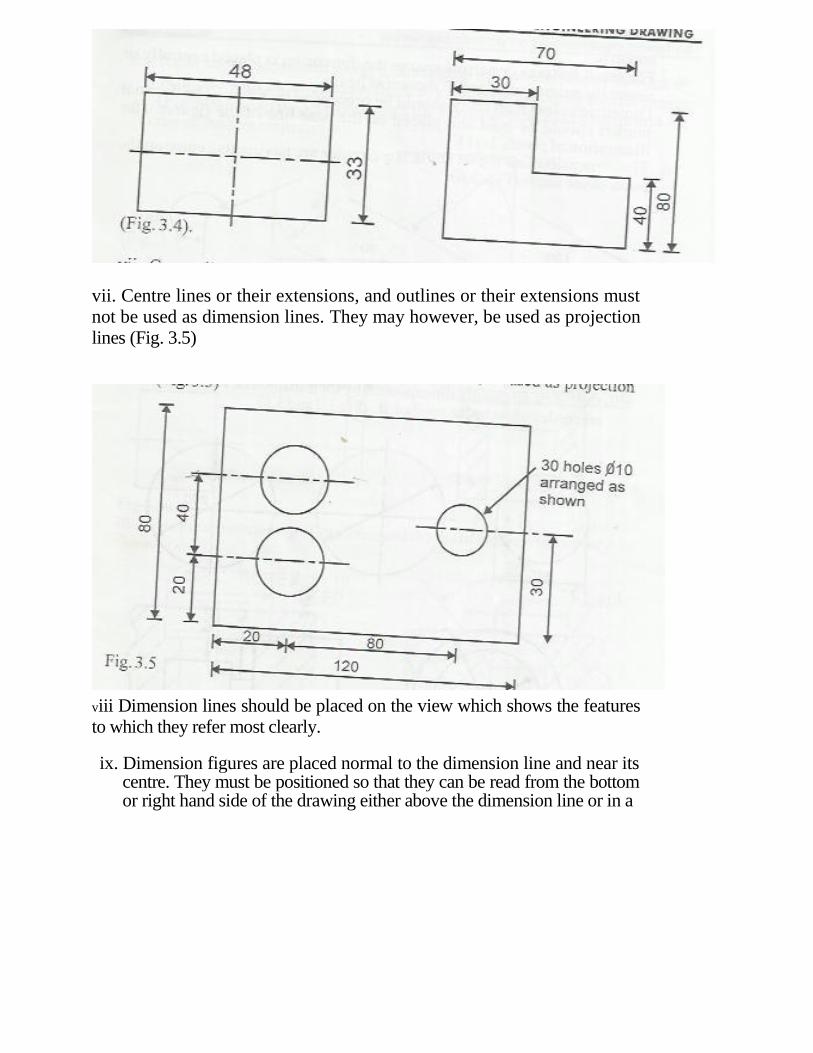
(vi) Smallest dimension should be placed nearest the outline to avoid
dimension and projection lines crossing (Fig. 3.4)
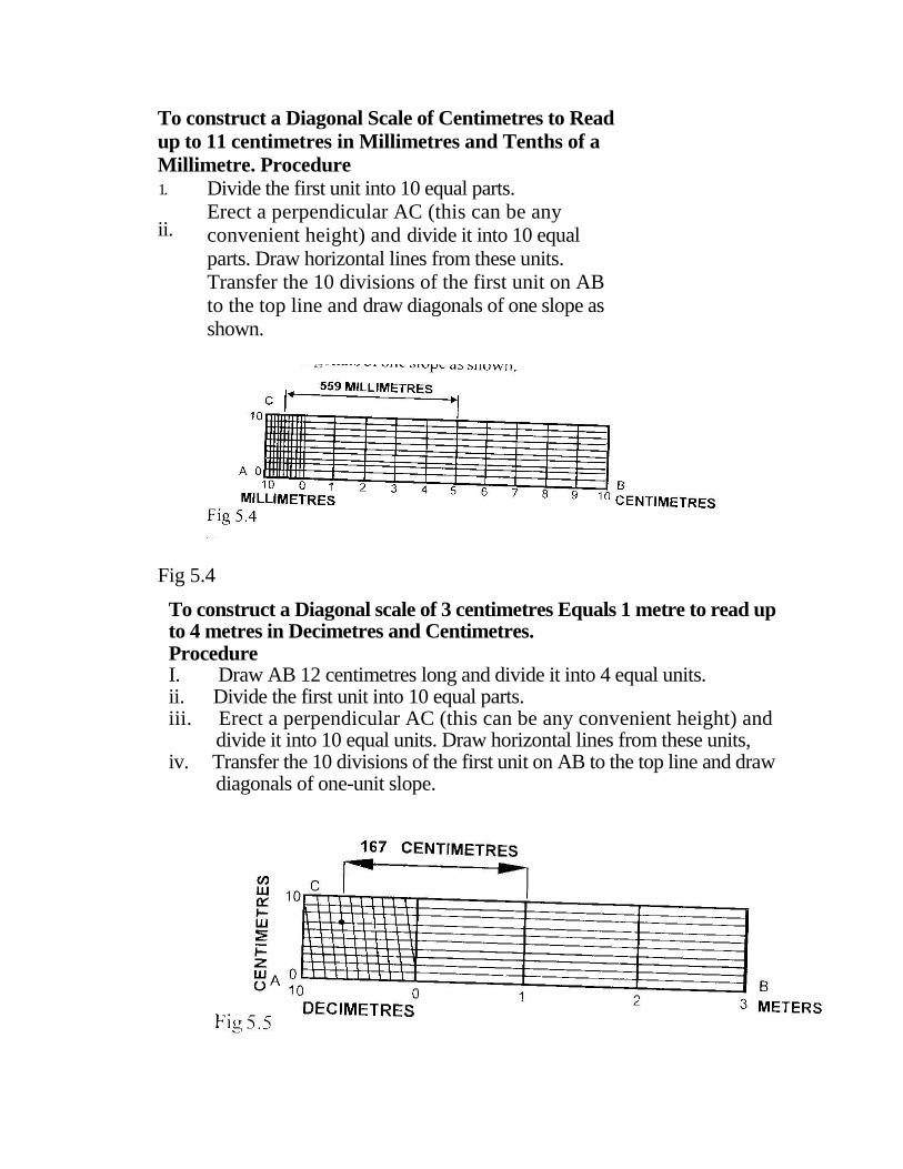
vii. Centre lines or their extensions, and outlines or their extensions must not be used as dimension lines. They may however, be used as projection lines (Fig. 3.5)
viii Dimension lines should be placed on the view which shows the features to which they refer most clearly.
ix. Dimension figures are placed normal to the dimension line and near its centre. They must be positioned so that they can be read from the bottom or right hand side of the drawing either above the dimension line or in a

gap in it. x. For small features or narrow spaces the dimension is placed centrally or
above the extension of one of the arrow heads, xi Dimensions less than unity should be preceeded by a zero. The decimal
marker should be bold and placed on the base line of the figures, (for
illustration of points 1-11). xii. The dimension line for an angle is a circular arc having its centre on the
point of the angle (Fig. 3.6)
xiii. Complete circles are dimensioned by their diameters, the dimension is
preceded using by the symbol 0. (Fig3.7and3.8)
Fig. 3.7
Fig. 3.8

xiv. Radii are dimensioned using a dimension line which passes through or is in line with the arc centre, the abbreviation R precedes the dimension (Fig 3.9) Fig 3.10-3.11 illustrates the dimensioning of chamfers and the use of leaders respectively.

3.7 MARGIN, BORDER LINES AND TITLE BLOCK
MARGIN
A margin is provided around the sheet by drawing margin lines. The provision of margin lines will enable prints to be trimmed along margin lines. Prints after trimming would be of recommended sizes of sheets. The margin for different sizes of different sizes of drawing sheet is shown in 3.14 & 3.15

•BORDER LINES
The clear working space on the drawing sheet is obtained by drawing border lines. In general practice, more space is kept on the left side for filing or binding when necessary.
TITLE BLOCK
Title block is an important feature in drawing because it gives all the
information of the prepared drawing. It is provided at the right hand bottom
corner of the sheet. All the blocks should contain at least the following
information. Name of firm/institution, your name, Matriculation Number,
Scale, Dimension, title of drawing, Drawing Number, Date/symbol
denoting the method of projection. (See table 2.3)
160mm
80m
LANDMARK UNIVERSITY OMU ARAN
NAME
MATRIC NUMBER
TITLE OF DRAWING
DRAWING NUMBER
DIMENSION
SCALE/SYMBOL
DATE

CHAPTER 4
4.0 LINES AND ANGLES
4.1 CONSTRUCTION OF ANGLES
To construct an Angle of 60°
Procedure
1. Draw a line AB.
2. Indicate point C anywhere on AB
3. With centre C and any convenient radius draw an arc to cut AB at D
4. with centre D and the same radius draw an arc to cut the previous one
at E.
5. Draw a line from C through E (line CF). FCB is the required 60°
angle.

Fig 4.1

To construct an Angle of 30° (See Fig 4.2)
Procedure
i. Construct an angle of 60 , as in Fig 4.1
ii. Bisect the 60 angle.
iii. Angle ABC is the required 30° angle.
Fig. 4.2 B
To construct an Angle of 15° (See Fig 4.3) Procedure
i. Construct an angle of 30°, as above
ii. Bisect the 30° angle.
iii. Angle 1,2,3 is the required 15° angle.
Fig. 4.3

To construct an Angle 45
Procedure
1. Construct a right angle BAC 2. Bisect the right angle to obtain a 45 angle.
Fig. 4.4
Construction of angle 90° using compasses
(Fig. 4.5)
Given: (i) Let line AB be a given line with point C at which the right angle 90° is to
be drawn, (ii) With centre C and any convenient radius, draw the semi-circle touching
the line AB at D and E. (iii) With centres D and E and radius DE draw two arcs which intersect at F.
Join F to C. (iv) Angles FC A and FCB are each 90° F
F
A D C E B
(Fig. 4.5)

To Construct a paralle line Fig(4.6)
Procedure. i. Draw the line AB. Mark points 1 and 3 near to the ends of the line and
point 2 about the centre of the line, ii With centres 1,2,3, and a radius equal to the distance away from the
required parallel line draw an arc. iii. A line drawn across the tops of the arcs is the required parallel line.
To construct a perpendicular at a Given point on a straight line (Fig 4.6)
To Construct a perpendicular at a given point on a straight line (Fig 4.7)
Procedure
i. Draw the given line AB ii Mark the given point C
iii With Centre C and any convenient radius draw the Semi Circle DE iv. With centres D and E and any convenient radius draw arcs to intersect at F. v. A line drawn from C through the intersection of the arcs is the perpendicular.

To bisect a Given line (Fig 4.8)
Procedure
i. Draw the given line AB
ii. With centre A and any radius greater than half AB, draw arcs above and
below the line
iii. With Centre c draw arc of the same radius to cut the previous ones iv. The line drawn through the intersections of the arcs will bisect the given
line AB at C.
Division of a line into number of equal part (Fig 4.9)
Construction: To divide a given straight line into a number of equal parts.
Procedure:
i. Draw the given line AB
ii. From one end of the line (Say A) draw AC at any convenient angle. iii. Mark off from A on AC the required number of equal parts using a scale
(you can choose any suitable length. iv. Join the last point to B on the given line, v. Through the other points, draw parallels to this line to cut the given line.

CHAPTER 5
5.0 SCALE DRAWING
5.1 IMPORTANCE OF SCALES IN DRAWING
Generally, it is easier to produce and understand drawings if they represent the true size of the object. This of course not always possible and it is often necessary to draw enlargements of very small objects and reductions of very large ones. Drawing are also printed by methods which can enlarge or reduce the actual productions, so knowledge of the true size of the subject matter on the drawings is most desirable.
All drawings should be drawn in proportions, that is to a uniform scale, and the scale used should be stated on the drawing as a ration. Normally, scale multiples and divisors 2,5,10 are recommended.
5.2 TYPES OF SCALE
There are two types of scale
i. Plain/simple scale ii. ii Diagonal scale
PLAIN SCALE. An object is often too large to be drawn full size on paper, so a
convenient scale is used. If an object is drawn half size, the scale is said to be half full size. The fraction ½ is known as the representative fraction, R.F.
The representative fraction (R.F)
distance drawn
distance represented
Also, length of scale=R.F x Maximum length

POINTS TO DRAW SCALE
In every scale, the following Key points should be remembered while constructing a scale.
1. Find the representative fraction (R. F.), If not given 2. Find the length of scale=R. F. X actual length of the object 3. The mark O (Zero) should be placed at the end of the first main
division 4. The main units should be numbered to the right and it's sub-units to
the left from the zero mark. 5. The scale or its R F. Should be mentioned along with the figure 6. The name of main unit and its sub-units should be mentioned either
below or at the respective ends of the scale.
To construct a scale of 2 centimeters equals 1 metre to read up to 6 metres in Decimeters.
Procedure:
i. Draw a line 120mm
ii. The height of the scale can be any convenient height iii. Divide the first unit into 10 equal parts
Fig 5.1
To construct a scale of 3 centimetres equals 1 Decimetre to Read up to 4
Decimetres in centimetres.
Procedure
i. Draw a line 120mm long and divide it into 4 equal parts. ii.
The height of the scale can be any convenient height. iii.
Divide the first unit into 10 equal parts.

To construct a scale of \1A times full size to read up to 8 centimetres
in millimetres.
Procedure
i. Draw a line 120mm long ( ½ x 8 centimetres) and divide it into
8 equal units,
ii. The height of the scale can be any convenient height.
iii. Divide the first unit into 10 equal parts.
DIAGONAL SCALE
With a diagonal scale it is possible to measure to a fine degree of
accuracy with 3 units of measurement, e.g Centimetres, millimetres and
tenths of a millimetre.
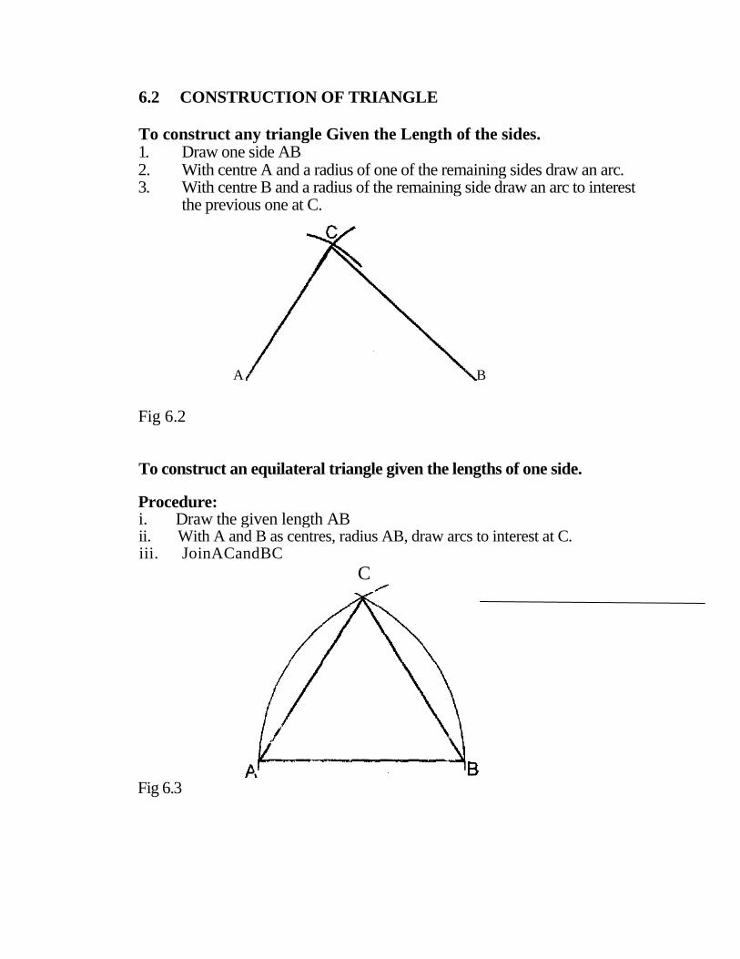
To construct a Diagonal Scale of Centimetres to Read
up to 11 centimetres in Millimetres and Tenths of a
Millimetre. Procedure
Divide the first unit into 10 equal parts. Erect a perpendicular AC (this can be any convenient height) and divide it into 10 equal
parts. Draw horizontal lines from these units. Transfer the 10 divisions of the first unit on AB to the top line and draw diagonals of one slope as shown.
Fig 5.4
To construct a Diagonal scale of 3 centimetres Equals 1 metre to read up
to 4 metres in Decimetres and Centimetres. Procedure
I. Draw AB 12 centimetres long and divide it into 4 equal units. ii. Divide the first unit into 10 equal parts. iii. Erect a perpendicular AC (this can be any convenient height) and
divide it into 10 equal units. Draw horizontal lines from these units, iv. Transfer the 10 divisions of the first unit on AB to the top line and draw
diagonals of one-unit slope.
1.
ii.
iii

CHAPTER 6
6.0 CONSTRUCTION OF PLANE FIGURES
6.1 DEFINITIONS
Triangles: A triangle is a plane figure bounded by three straight lines.
Some of the names given to triangle are as follows.
TYPES OF TRIANGLES AND ITS PROPERTIES
i. Scalene triangle: Has all sides and all angles unequal
ii. Equilateral triangle: Has all sides and all angles equal.
iii. Isosceles triangle: Has two sides of equal length and two equal angles.
iv. Right angled triangle: Has one angle that side positioned opposite to the
right HYPOTEN USE and is the longest side.
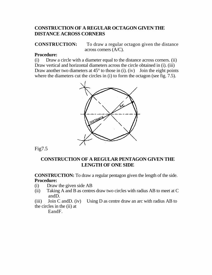
6.2 CONSTRUCTION OF TRIANGLE
To construct any triangle Given the Length of the sides. 1. Draw one side AB 2. With centre A and a radius of one of the remaining sides draw an arc. 3. With centre B and a radius of the remaining side draw an arc to interest
the previous one at C.
Fig 6.2
To construct an equilateral triangle given the lengths of one side.
Procedure:
i. Draw the given length AB
ii. With A and B as centres, radius AB, draw arcs to interest at C. iii. JoinACandBC
C
Fig 6.3
A B

To construct an Isosceles triangle, given the length of the base and the perpendicular height.
Procedure:
i. Draw the given base AB
ii. Bisect the base at D. iii. With D as centre and given height as radius, draw an arc above AB. iv. Erect a perpendicular at D to cut the arc at C. v. Join AC and BC.
Fig 6.4.
To construct a triangle, given the length of two sides and the
perpendicular height. Procedure:
I. Draw a base line of any convenient length. ii. Erect a perpendicular at D
iii. Mark off the height CB
iv. With C as centre and the two given lengths as radii, mark off CA and CB respectively. v. Join AC and BC.
Fig. 6.5.

PAGE 39
To construct a triangle given the three-sides and to draw the inscribed
circle. Procedure
i. Draw AB to represent one side. ii. With A and B as centres radius AB, draw arcs to interest at C. iii. Join AC and CB. iv. Bisect angles CAB and ABC and the intersection will give the required
circle. C
Fig. 6.6.
To construct a triangle given the one side and two angles and to draw the
circumscribing circle. Procedure
i. Draw AB to represent one side, ii Draw an angle at point A and other angle at point B. iii. The intersection of the sides will give the apex C. iv. Bisect AC and BC (any 2 sides) and the intersection give the centre of the circle.
Fig 6.7.
B
C
B

6.3 QUADRLILATERALS
Quadrilaterals are plane figures bounded by four straight lines.
TYPES AND PROPERTIES OF QUADRILATERALS
A. SQUARE: A square has all sides equal and all angles are right angles.
B. RECTANGLE: A rectangle has all its opposite sides equal and all angles are right angle.
C. RHOMBUS: A rhombus has all its sides and opposite angles equal but contains no right angles.
D. PARALLELOGRAM: A parallelogram has its opposite pairs of sides and opposite angles equal but contains no right angle-Diagonal bisect each other, either diagonal will divide the figure into two similar triangle of equal area.
E. TRAPEZIUM: A trapezium has two sides parallel. F. TRAPEZOID:- Has 4 unequal sides and angles
G. DELTOID:- A deltoid or kite has its adjacent pairs of sides of 'equal length.

6.4 CONSTRUCTION OF QUADRILATERAL
Fig. 6.9 Construction of parallelogram
Constructions a parallelogram ABCD with AB =50mm, BC = 70mm and angle ABC = 60°. Procedure: (;) Draw an angle of 60° at B, with centre B and radius 50mm, position point A, similarly with radius of 70mm, establish point C. From A, draw an arc of 70mm to intersect with arc of 50mm from C. The intersections gives point D.
Fig. 6.9 B

CHAPTER SEVEN
7.0 POLYGONS
Definition: A polygon is a close figure having many sides that are straight.
The following are
Triangle
Quadrilateral
Pentagon
Hexagon
Septagon
Octagon
Nonagon
Decagon
Undecagon
Duodecagon
examples of polygon.
= Three sided polygon
= Four sided polygon
= Five sided polygon
= Six sided polygon
= Seven sided polygon
= Eight sided polygon
= Nine sided polygon
= Ten sided polygon
= Eleven sided polygon
= Twelve sided polygon

In any regular polygon with N sides, the exterior angles as well as the angles subtended by the side at the centre are each equal to 360/N. The sides are also equal.
7. 1 CONSTRUCTION OF POLYGONS
CONSTRUCTION OF A REGULAR HEXAGON GIVEN DISTANCE ACROSS FLATS.
CONSTRUCTION: To draw a regular hexagon given the distance across flats (A/F).
Procedure:
(i) Draw a circle with a diameter equal to the distance across flats. (ii) Using a 60° set square draw six tangents to this circle. (Hi) Produce the hexagon (Fig 7.1)
t
The points where the tangents meet are the coners of the hexagon.
Fig. 7.1

CONSTRUCTION OF A REGULAR HEXAGON GIVEN DISTANCE ACROSS CORNERS
CONSTRUCTION: To draw a regular hexagon given the distance
across corners (A/C). Procedure:
(i) Draw a circle with a diameter equal to the distance across corners, (ii) Step off the radius round the circle to give six equally spaced points, (iii) Form the hexagon by joining these points (see Fig. 7.2)
Fig. 7.2
CONSTRUCTION OF A REGULAR POLYGON GIVEN DISTANCE ACROSS FLATS
CONSTRUCTION: To draw a regular octagon given the distance
across flats (A/F). This can be done by two methods.
METHOD (a) Procedure:
(i) Draw a circle with a diameter equal to the distance across flat (A/F). (ii) Using a 45 degree side of a set square draw eight tangents 45° to this
circle, (iii) Produce the octagon. The points where the tangents meet at the corners
of the octagon (see Fig. 7.3)

Fig. 7.3
METHOD (b)
GIVEN: The distance across flat of a regular octagon
REQUIRED: To construct a regular octagon
Procedure:
(1) Draw a square whose side equals the given distance across flats ABCD
shown in Fig. 7.4
(ii) Draw the diagonals AC and BD to intersect at O. (iii) With A as centre and radius OA, draw an arc to cut AD and AB at E and F. (iv) Repeat step (iii) for B, C and D. as centres. (v) Join the points E, J, K, G, L, I, A to give the required octagon.
CONSTRUCTION OF A REGULAR OCTAGON GIVEN THE
DISTANCE ACROSS CORNERS
CONSTRUCTION: To draw a regular octagon given the distance
across corners (A/C). Procedure:
(i) Draw a circle with a diameter equal to the distance across corners. (ii) Draw vertical and horizontal diameters across the circle obtained in (i). (iii) Draw another two diameters at 45° to those in (i). (iv) Join the eight points where the diameters cut the circles in (i) to form the octagon (see fig. 7.5).
Fig7.5
CONSTRUCTION OF A REGULAR PENTAGON GIVEN THE
LENGTH OF ONE SIDE
CONSTRUCTION: To draw a regular pentagon given the length of the side. Procedure:
(i) Draw the given side AB
(ii) Taking A and B as centres draw two circles with radius AB to meet at C
andD. (iii) Join C andD. (iv) Using D as centre draw an arc with radius AB to the circles in the (ii) at
EandF.

(v) Note the point where the arc in (iv) cuts CD, say point G.
(vi) Join EG and FG.
(vii) Produce EG and FG to H and J respectively on the circles in (ii).
Fig. 7.6