orthodontic movement using pulsating force induced peizoelctricity
TRANSCRIPT
Orthodontic movement using pulsating force-induced piexoelectricity E. Shapiro, F. W. Roeber, and L. S. Klempner Boston. Mass.
P iezoelectricity may be a means of achieving physiologic tooth movement. The generation of piezoelectricity in response to the mechanical deformation of bone has been reported by a number of researchers. l-6 When bone is deformed, there are generated piezoelectric charges which vary directly with the magnitude of the induced stress.6 These charges induce microcurrents to flow through bone and soft tissue’ and may enhance tooth movement by stimulating osteoblastic and osteoclastic activity. The microcurrents flow only during the application or release of stress6 and are not observed where continuous orthodontic forces are used. It is believed that the inducement of piezoelectric charges by the application of pulses of force to teeth can achieve and accelerate osteogenic response. In this study, tooth movement is evaluated as pulsating (intermittent) forces are applied to maxillary molars with the ultimate objective of achieving physiologic tooth movement.
Background
Yasuda and associates’ exerted pressure on a femur and observed callus formation in the periosteum and endosteum. Potentials were negative for bone under compression and positive for bone under tension, thus demonstrating that mechanical forces can induce a polarized electric surface charge. Further investigations of Fukada and Yasuda* attributed the generation of piezoelectricity to the deformation of the crystalline structure of collagen.
In a study of bone bending, Grimm4 found that bone may actually be under tension on the classic “pressure” side and compression on the classic “tension” side. The advancing tooth may “bend” the septal bone creating tension, thus producing the positive piezoelectric charges associated with osteoclastic activity. The trailing wall is pulled by the periodontal fibers causing alveolar bending, compression, negative piezoelectric charges, and osteoblastic activity. In his investigation, Grimm speculated that orthodontic tooth movement in response to a given force is related to the magnitude of alveolar deflection and to root surface area. Grimm hypothesized that a strain-induced electrical or chemical phenomenon may be the link between mechanotherapy and alveolar bone response.
Cochrar? observed bone formation using the direct application of 10 microamperes of current. Bassett7 concurred that direct current stimulates the rate of osteogenesis and
From Tufts University School of Dental Medicine. Presented in part before the Research Section of the Northeastern Society of Orthodontists, New York, N. Y., November, 1977. This study was supported by Research Grant 1 Rol DE04487-01, National Institute of Dental Re- search.
0002-9416/79/070059+08$00.80/O 0 1979 The C. V. Mosby Co. 59
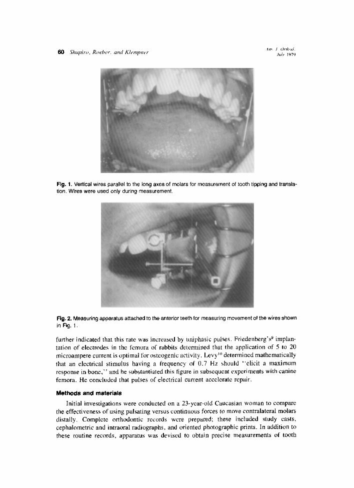
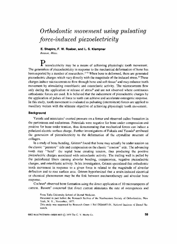
Fig. 1. Vertical wires parallel to the long axes of molars for measurement of tooth tipping and transla- tion. Wires were used only during measurement.
Fig. 2. Measuring apparatus attached to the anterior teeth for measuring movement of the wires shown in Fig. 1.
further indicated that this rate was increased by uniphasic pulses. Friedenberg’ss implan- tation of electrodes in the femora of rabbits determined that the application of 5 to 20 microampere current is optimal for osteogenic activity. Levy lo determined mathematically that an electrical stimulus having a frequency of 0.7 Hz should “elicit a maximum response in bone,” and he substantiated this figure in subsequent experiments with canine femora. He concluded that pulses of electrical current accelerate repair.
Methods and materials
Initial investigations were conducted on a 23-year-old Caucasian woman to compare the effectiveness of using pulsating versus continuous forces to move contralateral molars distally. Complete orthodontic records were prepared; these included study casts, cephalometric and intraoral radiographs, and oriented photographic prints. In addition to these routine records, apparatus was devised to obtain precise measurements of tooth

Volume 16 Number I
Pulsating force-induced piezoelectricity 61
Fig. 3. Tooth mobility sensor connected by a nylon line to the molar.
Fig. 4. Acrylic appliance with bands, actuator for pulsating force, and rod for continuous force.
position, angulation, and mobility on both the pulsed and the control teeth. Tooth tipping and translation were monitored by measuring movement of the ends of a
vertical wire attached to the buccal surface of each molar and oriented parallel to the long axis (Fig. 1). The measurement apparatus was affixed with an acrylic splint to the teeth anterior to the molars (Fig. 2). These measurements were recorded in both the sagittal and frontal planes. Positional and angular changes of both molar teeth were thus obtained.
A sensor was devised to record mobility of 0.00001 inch or greater. A nylon line extended from the sensor to a vertical pin attached to the molar (Fig. 3). A strain gauge affixed to the sensor converted movement of the tooth into electrical signals that were recorded on an oscillograph. The mobility device is frictionless and imposes a negligible force on the test tooth. Its low mass allows it to record the instantaneous movement of the molar during pulsing. A standard mobility test was performed periodically by means of a

Fig. 5. Force applicator appliance with restraining headgear
wire plunger extending through the acrylic.appliance to the orthodontic band on the test tooth. Mobility was monitored as an elastic activated the plunger. Comparison mobility tests were conducted on both the control and the test teeth.
An acrylic appliance was designed to provide a platform from which to deliver the forces (Fig. 4). To prevent anterior movement of the maxillary teeth, a Northwest type of headgear was attached to the acrylic appliance (Fig. 5). Throughout the test period a continuous force of 18 ounces was applied to the control tooth, and a pulsating force of 30 ounces peak (20 ounces average) was applied to the test tooth. The force to the control tooth was supplied by three elastics activating a wire plunger. The force to the test tooth was supplied by a pneumatic actuator consisting of a cylindrical metal housing encasing a piston. The cylindrical housing interlocks into a metal socket in the acrylic appliance, and a rod attached to the piston extends to an orthodontic band on the molar (Fig. 6). A timing circuit operates a pneumatic valve, thereby controlling the inlet of pressurized air into the actuator. The magnitude of air pressure in the cylinder determines the amount of force exerted on the molar. When the valve is closed, the air in the cylinder is allowed to leak out at a controlled rate, decreasing the force on the tooth proportionately.
The system has been designed to operate in this manner to induce unidirectional microcurrents in the alveolar bone. To achieve the maximum charge build-up and to overcome charge neutralization, it is necessary to use a high rate of force application.6 Abrupt removal of the force would produce an opposite polarity charge and microcurrent flow in the opposite direction.” In order to minimize the generation of an opposite polarity-piezoelectric charge, the force is removed slowly, relieving the stress within the bone7 (Fig. 7). Pulses are repeated at a frequency of 0.7 Hz.‘O Orthodontic elastics were used to apply continuous forces to the control molar.
One of us (F. W. R.) conducted tests to determine the force decay of the elastics as used on the control side. Three elastics were stretched the same distance as in the reported study, thereby developing the force used on the control side. The following data were obtained:

Volume 76 Number I
Pulsating force-induced piezoelectricity 63
Fig. 6. Pneumatic pulsating force actuator to move test molar.
Time (hrs.) Force (oz.)
0 20 I 20 9.5 20
20.0 19.75 24 19.75
Hence, the force decay was practically negligible, even after 24 hours. Previous investigators have noted as much as 25 percent force reduction, but this decay was probably because of elastics being used inside the mouth as opposed to extraoral use as in this study. The test gauge incorporated a “last word indicator” commonly used in deflection measurement.
Results
Pulses of force have produced sustained movement rates of 0.2-0.3 x 10-a inches per hour when applied to the patient’s maxillary left second molar. Initial testing with 10 ounce pulses (6 ounces average) produced low and erratic rates of movement. By increas- ing the pulsing force to above 8 ounces, 56 x lo-” inches of crown movement was achieved during 180 hours of pulsing (Fig. 8). The test period extended over 40 nights for an average of only 4.5 hours of pulsing per night.
A continuous force of 18 ounces on the control tooth was 2 ounces less than the average magnitude of the pulsed force. In pulsing, the peak force applied to the tooth was maintained for 0.2 second and then slowly decreased during the remaining 1.2 seconds of the cycle to a sustained level of 8 ounces. During the cycle this produced an average force of 2Oounces on the pulsed tooth. The rate of movement as well as the total movement of the pulsed tooth was greater than the control tooth (Fig. 9). Throughout the experiment tooth mobility was minimized when a sustained force of 8 ounces was maintained by the actuator.
The patient’s response to pulsating forces has been favorable. Pain was experienced on the control side from time to time throughout the experiment but not on the pulsed side. The patient reported that the force pulsations were just barely perceptible, that she was not usually aware of them, and that they did not interfere with sleep.

PULSATING FORCE PARAMETERS ( TRACE OF OSCILLOGRAPH RECORDING )
t PEAK FORCE
i
PULSE
-I- 4PPLICATION
I= PER’oD -4 DURATION OF CONTINUOUS PULSING
TIME
Flg. 7. Pulsating force parameters (tracing of oscillograph recording). Period = Time between the leading edges of two successive pulses (1.4 seconds). Pulse application rime = Time required to reach the peak force (20 msec.). Peak force = Maximum force level achieved during the pulse cycle (900 Gm). Pulse width = Time duration of maximum force application (0.2 second). Force removal time = Trailing edge of the pulse extending from the end of the peak force pulse to the beginning of the next pulse (1.2 seconds). Sustained force = Force still acting on tooth at end of pulse period (240 Gm.). Duration of continuous pulsing = Number of pulses applied during a treatment session, multiplied by the pulse period.
MOVEMENT OF PULSED 8 CONTROL TEETH
l Pulsed
60
100 200 300 400 500 600 700
HOURS OF TESTING
Fig. 8. Movement of pulsed and control teeth.
The accuracy of the measuring systems developed for the project permits precise monitoring of patient responses and thus rapid evaluation of experimental parameters. The accuracies of the measurement apparatus are kO.002 inch for position, kO.25 degree for rotation, and +-0.001 inch for mobility. The mobility sensor system provides noise-free oscillograph registrations of 0.06001 inch or more of crown movement, although we record movement to the nearest 0.001 inch. The mobility measurements are made over short intervals and are therefore not subject to temperature-induced changes of the nylon line. The sensor exerts a constant fraction of an ounce of force on the line during the mobility test and therefore does not subject the line to force gradients which would stretch

Volume 76 Number I Pulsating force-induced piezoelectricity 65
RATE OF MOVEMENT VS TOOTH MOVEMENT
l- z $i a .6- l Pulsed $ $ 0 P$- ,5- Conlrol
E” .4-
8” .3-
l-r.0 b w .2-
pz *‘-
2 , ,+(fy-,
10 20 30 40 50 60 70 80 90 100
TOOTH MOVEMENT
1 INCHES X 1O-3)
Fig. 9. Rate of movement versus tooth movement.
MOBILITY OF PULSED 8 CONTROL TEETH
l Pulsed 30- 0 Control
10
100 200 300 400 500 600 700
HOURS OF TESTING
Fig. 10. Mobility of pulsed and control teeth.
it at one time more than at any other time. Hence, reliable comparative measurements can be made on the test and the control teeth.
The force applicator system has delivered more than 2.5 million pulses throughout the testing without a failure.
Summary
According to Steinberg and associate? and Bassett,’ piezoelectric charges are gen- erated in response to the mechanical deformation of bone and these charges induce microcurrents to flow through bone and soft tissue. The direction of current, amperage, and wave form are all critical considerations in maximizing the effects of piezoelectricity. In summarizing recent concepts, CochratP recommends the direct application of a con- tinuous or pulsed current of 10 microamperes to optimize bone deposition at the cathode. Friedenberg’ss implantation of electrodes in the femora of rabbits determined an optimal current of 5 to 20 microamperes for optimum bone formation, both osteoblastic and osteoclastic. There is evidence that nonoscillatory electric fields and DC currents can be osteogenic. Friedenberg and associates used DC currents.

Levy’” determined mathematically that a stimulus having a frequency of0.7 Hz should “elicit a maximum response in bone.” and he substantiated this tigure in subsequent experiments with canine femora. He concludes that the use of pulsed signal sources can accelerate repair. Cochran points out that the frequency of 0.7 Hz corresponds closely with the natural frequency of walking.
An appliance and instrumentation have been designed and constructed to apply pulsat- ing forces for the distal movement of maxillary molars. Devices have been developed to determine tooth position, angulation, or tipping and mobility-both static and dynamic. These measurements are carried out to 0.002 inch, to 0.25 degree, and to 0.001 inch, respectively. Clinical testing has been initiated on one patient, and sustained distal crown movement has been indicated in 180 hours. Perhaps more data would enhance the study, and at present additional subjects are being investigated. Although only one patient was used in the present study, the data gathered will, as far as we know, represent the only information reported in the literature on pulsating-force-induced movement of teeth. We will conduct further investigations optimizing parameters of force magnitude, pulse dura- tion and period, and force application and removal rates.
REFERENCES 1. Yasuda, I., Nogucki, K., and Sata, T.: Dynamic callus and electrical callus, J. Bone Joint Surg. 37A:
1291-1293, 1955. 2. Fukada, E., and Yasuda, I.: On the piezoelectric effect of bone, J. Physiol. Sot. Jpn. 12: 115% 1162, 1957. 3. Steinberg, M. E., Bosch, A., Schwan, A., and Glazer, R.: Electrical potentials in stressed bone, Clin.
Orthop. 61: 294-299, 1968. 4. Grimm, F. M.: Bone bending, a feature of orthodontic tooth movement, AM. J. ORTHOD. 62: 384-393,
1972. 5. Zengo, A. N., Pawluk, R. J., and Bassett, C. A. L.: Stress-induced bioelectric potentials in the dentoalveo-
lar complex, AM. J. ORTHOD. 64: 17-27, 1973. 6. Steinberg, M. E., Busenkell. G. L., Block, J., and Korostoff E.: Stress-induced potentials in moist bone in
vitro, J. Bone Joint Surg. 56: 704-713. 1974. 7. Bassett, C. A. L.: Biologic significance of piezoelectricity, Calcif. Tissue. Res. I: 252-272. 1968. 8. Cochran, G. V. B.: Experimental methods for stimulation of bone healing by means of electrical energy.
N. Y. Acad. Med. 48: 899-91 I, 1972. 9. Friedenberg. Z. B.. Andrews, E. T.. Smolensky. B. Q., Pearl. B. W., and Birghton. C. T.: Bone reaction
to varying amounts of direct current, Surg. Gynecol. Obstet. 131: 894-899, 1970. 10. Levy, D. D.: A pulsed electrical stimulation technique for inducing bone growth, N. Y. Acad. Sci. 238:
478-490, 1974. 11. Bassett, C. A. L.: Biophysical principles affecting bone structure: The chemistry and physiology of bone.
ed. 2, New York, 1971, Academic Press, vol. 3, pp. l-76.