oregon joint use association standards · pdf fileoregon joint use association standards...
TRANSCRIPT
OREGON JOINT USE ASSOCIATION
STANDARDS COMMITTEE
BEST PRACTICES GUIDE
APRIL 2009
ACKNOWLEDGMENTS
Construction Standards Subcommittee
Membership
Dave Cheney, Accent Communications
Stan Cowles, Qwest
Jim Flu, PacifiCorp
Keshvar Jafari, PGE
Scott Jennings, Verizon
Tamara Johnson, Springfield Utility Board
Rob Kolosvary, PGE
Gary Lee, Charter Communications
Jeff Liberty, Bend Broadband
Jim McGuire, PGE
Michelle Ness, Central Lincoln PUD
Gary Payne, Qwest
Gary Putnam, PUC
Troy Rabe, Comcast
Stuart Sloan, Consumers Power
John Wallace, PUC
Jim Watkins, PacifiCorp
Scott Wheeler, Comcast
Bill Woods, PacifiCorp
TABLE OF CONTENTS
Chapter 1 - Anchors ........................................................................................................................................................... 1
A. Placement Considerations: ................................................................................................................................ 1
B. Common Types of Anchors and Installation ............................................................................................ 4
Testing the Anchor: ...................................................................................................................................................... 8
Chapter 2 - Bonding and Grounding ......................................................................................................................... 9
A. Definition of Bonding ............................................................................................................................................ 9
B. Bonding Installation Considerations ......................................................................................................... 10
C. Types of Bonds Installations: .......................................................................................................................... 10
D. Types of Bonding Connectors: ....................................................................................................................... 11
E. Definition of Grounded ....................................................................................................................................... 11
F. Grounding Installation Considerations ..................................................................................................... 11
G. Types of Grounds ................................................................................................................................................... 12
H. Street Light Grounding ....................................................................................................................................... 13
I. Bonding Risers ........................................................................................................................................................ 14
Chapter 3 - Framing ......................................................................................................................................................... 15
A. Definition of Framing .......................................................................................................................................... 15
B. Site Specific Construction ................................................................................................................................. 15
C. Types of Framing ................................................................................................................................................... 16
D. Avian Protection Construction ...................................................................................................................... 20
E. Construction Practices ........................................................................................................................................ 20
F. Ground Clearances ................................................................................................................................................ 20
G. Voltage Clearances................................................................................................................................................ 21
Chapter 4 - Poles ................................................................................................................................................................ 22
A. Definition of a Pole ............................................................................................................................................... 22
B. Placement .................................................................................................................................................................. 22
C. Types ............................................................................................................................................................................ 22
D. Identification ........................................................................................................................................................... 23
E. Grades of Construction ....................................................................................................................................... 24
F. Pole Class:................................................................................................................................................................... 24
G. Pole top Extensions .............................................................................................................................................. 25
H: Pole Supports: ......................................................................................................................................................... 26
Chapter 5 - Risers .............................................................................................................................................................. 29
A. Definition of Riser ................................................................................................................................................ 29
B. Placement Considerations: .............................................................................................................................. 29
Chapter 6 - Tension and Sag ........................................................................................................................................ 34
A1. Definition of Tension ......................................................................................................................................... 34
A2. Definition of Sag ................................................................................................................................................... 34
B. Engineering Design .............................................................................................................................................. 35
C. Methods of Tensioning: ...................................................................................................................................... 35
D. SLACK SPAN (Reduced Tension Construction) ..................................................................................... 36
E. Guy Tension ............................................................................................................................................................. 36
F. Line of Sight ............................................................................................................................................................... 37
G. Sag Charts .................................................................................................................................................................. 37
H. Loading Zone: .......................................................................................................................................................... 38
I. Grades of Construction ....................................................................................................................................... 39
J. Resources: .................................................................................................................................................................. 40

Chapter 7 - Support Arms ............................................................................................................................................. 41
A. Definition of Support Arm ................................................................................................................................ 41
B. Placement considerations ................................................................................................................................ 41
C. Types: ........................................................................................................................................................................... 42
D. Braces: ......................................................................................................................................................................... 48
E. Lengths of Arms: ..................................................................................................................................................... 48
F. Pole Gains ................................................................................................................................................................... 49
G. Installation: .............................................................................................................................................................. 49
Chapter 8 - Equipment Pictorial ............................................................................................................................... 50
A. Definition of Equipment .................................................................................................................................... 50
B. General Equipment .............................................................................................................................................. 50
C. Supply Equipment ................................................................................................................................................. 52
D. Telco Equipment: .................................................................................................................................................. 54
E. Cable Equipment: ................................................................................................................................................... 55
F. Fiber Equipment ..................................................................................................................................................... 55
G. Wireless Equipment ............................................................................................................................................ 56
1
CHAPTER 1 - ANCHORS This document is intended to provide education on common Construction Practices for aerial construction of power and
telecommunications facilities. This is not an official codebook, nor should it be construed as a construction manual. When
constructing aerial facilities, please refer to the governing codes, such as the �ational Electrical Safety Code, �ational Electric
Code, Oregon Public Utility Commission Safety Rules, Oregon Occupational Safety And Health Administration, State, County
and Municipal codes, and all other applicable standards, including contracts.
The 2007 National Electrical Safety Code (NESC) addresses anchors in Sections 253, 261, and 264
Table of Contents:
A. Placement Considerations
B. Common Types of Anchors & Installation
A. PLACEMENT CONSIDERATIONS:
The distance between the anchor and the pole is generally based on the load the anchor is required
to hold, and the anchor type. There are other considerations that are dealt with in this chapter as
well.
Anchors are generally placed five (5) feet from an existing anchor. This is done to ensure the soil
surrounding the existing anchor is not loosened while installing the new anchor.
Heights to lead ratio means that for every one foot of pole height that place your attachment, you
place the anchor one foot away from the pole.
• 1:1 ratio is optimum
• 2:1 ratio is good
• 3:1 ratio is the minimum
When identifying the need to have your plant guyed at a specific location, you may observe
another utilities’ anchor. This anchor may have an available open eye. You must first get
permission from the anchor owner prior to occupying that open eye with your guy.
2
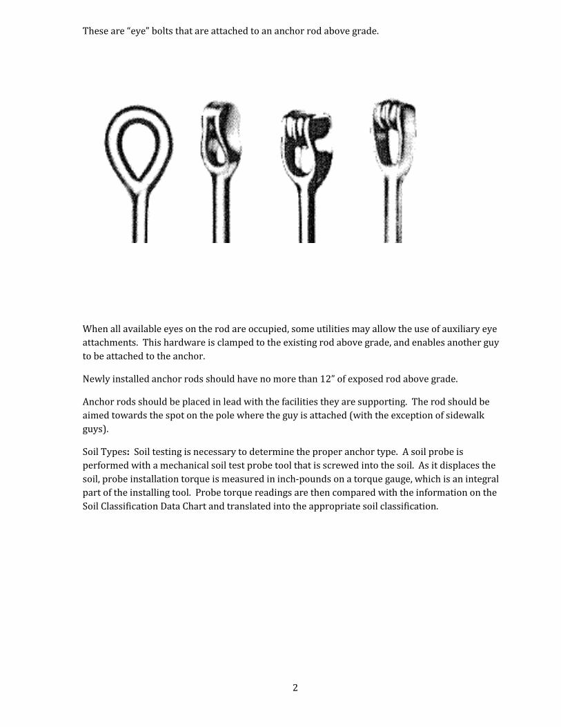
These are “eye” bolts that are attached to an anchor rod above grade.
When all available eyes on the rod are occupied, some utilities may allow the use of auxiliary eye
attachments. This hardware is clamped to the existing rod above grade, and enables another guy
to be attached to the anchor.
Newly installed anchor rods should have no more than 12” of exposed rod above grade.
Anchor rods should be placed in lead with the facilities they are supporting. The rod should be
aimed towards the spot on the pole where the guy is attached (with the exception of sidewalk
guys).
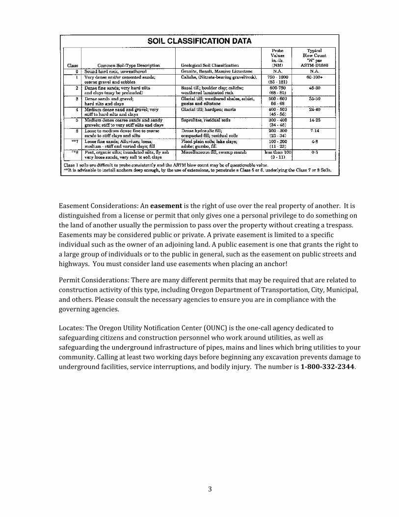
Soil Types: Soil testing is necessary to determine the proper anchor type. A soil probe is
performed with a mechanical soil test probe tool that is screwed into the soil. As it displaces the
soil, probe installation torque is measured in inch-pounds on a torque gauge, which is an integral
part of the installing tool. Probe torque readings are then compared with the information on the
Soil Classification Data Chart and translated into the appropriate soil classification.
3
Easement Considerations: An easement is the right of use over the real property of another. It is
distinguished from a license or permit that only gives one a personal privilege to do something on
the land of another usually the permission to pass over the property without creating a trespass.
Easements may be considered public or private. A private easement is limited to a specific
individual such as the owner of an adjoining land. A public easement is one that grants the right to
a large group of individuals or to the public in general, such as the easement on public streets and
highways. You must consider land use easements when placing an anchor!
Permit Considerations: There are many different permits that may be required that are related to
construction activity of this type, including Oregon Department of Transportation, City, Municipal,
and others. Please consult the necessary agencies to ensure you are in compliance with the
governing agencies.
Locates: The Oregon Utility Notification Center (OUNC) is the one-call agency dedicated to
safeguarding citizens and construction personnel who work around utilities, as well as
safeguarding the underground infrastructure of pipes, mains and lines which bring utilities to your
community. Calling at least two working days before beginning any excavation prevents damage to
underground facilities, service interruptions, and bodily injury. The number is 1-800-332-2344.
4
B. COMMON TYPES OF ANCHORS AND INSTALLATION
• Plate
• Helix / Screw
• Expanding / Bust
• Manta Ray
• Swamp
• Rock
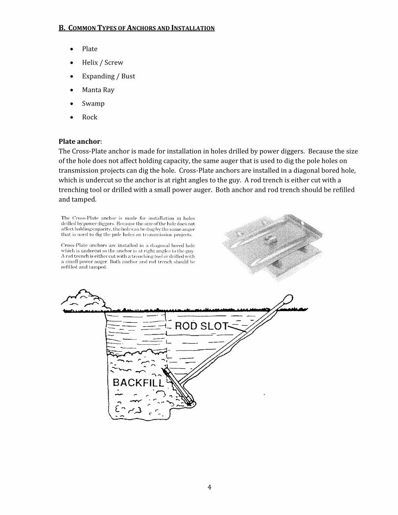
Plate anchor:
The Cross-Plate anchor is made for installation in holes drilled by power diggers. Because the size
of the hole does not affect holding capacity, the same auger that is used to dig the pole holes on
transmission projects can dig the hole. Cross-Plate anchors are installed in a diagonal bored hole,
which is undercut so the anchor is at right angles to the guy. A rod trench is either cut with a
trenching tool or drilled with a small power auger. Both anchor and rod trench should be refilled
and tamped.
5
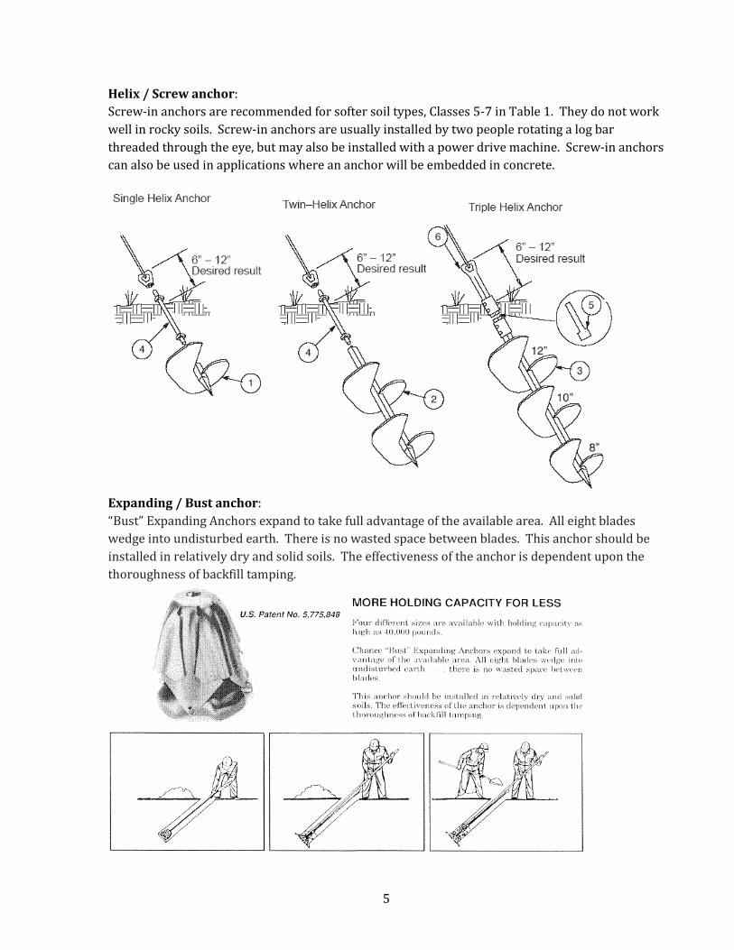
Helix / Screw anchor:
Screw-in anchors are recommended for softer soil types, Classes 5-7 in Table 1. They do not work
well in rocky soils. Screw-in anchors are usually installed by two people rotating a log bar
threaded through the eye, but may also be installed with a power drive machine. Screw-in anchors
can also be used in applications where an anchor will be embedded in concrete.
Expanding / Bust anchor:
“Bust” Expanding Anchors expand to take full advantage of the available area. All eight blades
wedge into undisturbed earth. There is no wasted space between blades. This anchor should be
installed in relatively dry and solid soils. The effectiveness of the anchor is dependent upon the
thoroughness of backfill tamping.
6
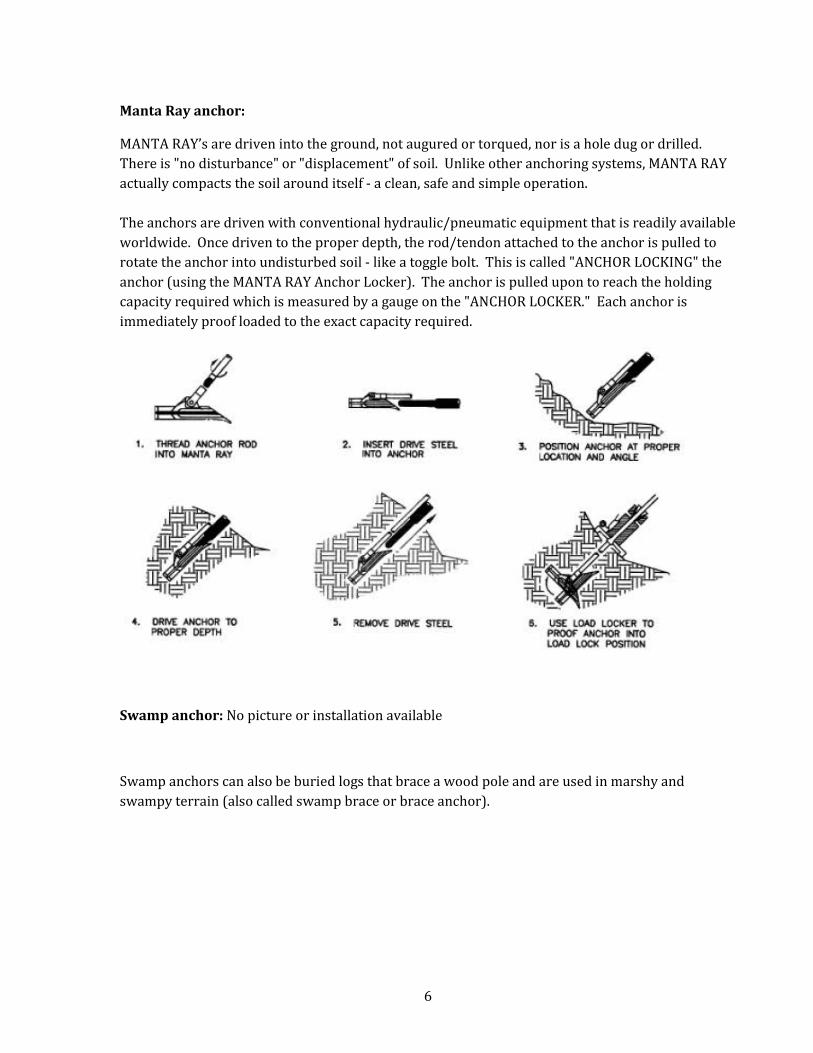
Manta Ray anchor:
MANTA RAY’s are driven into the ground, not augured or torqued, nor is a hole dug or drilled.
There is "no disturbance" or "displacement" of soil. Unlike other anchoring systems, MANTA RAY
actually compacts the soil around itself - a clean, safe and simple operation.
The anchors are driven with conventional hydraulic/pneumatic equipment that is readily available
worldwide. Once driven to the proper depth, the rod/tendon attached to the anchor is pulled to
rotate the anchor into undisturbed soil - like a toggle bolt. This is called "ANCHOR LOCKING" the
anchor (using the MANTA RAY Anchor Locker). The anchor is pulled upon to reach the holding
capacity required which is measured by a gauge on the "ANCHOR LOCKER." Each anchor is
immediately proof loaded to the exact capacity required.
Swamp anchor: No picture or installation available
Swamp anchors can also be buried logs that brace a wood pole and are used in marshy and
swampy terrain (also called swamp brace or brace anchor).
7
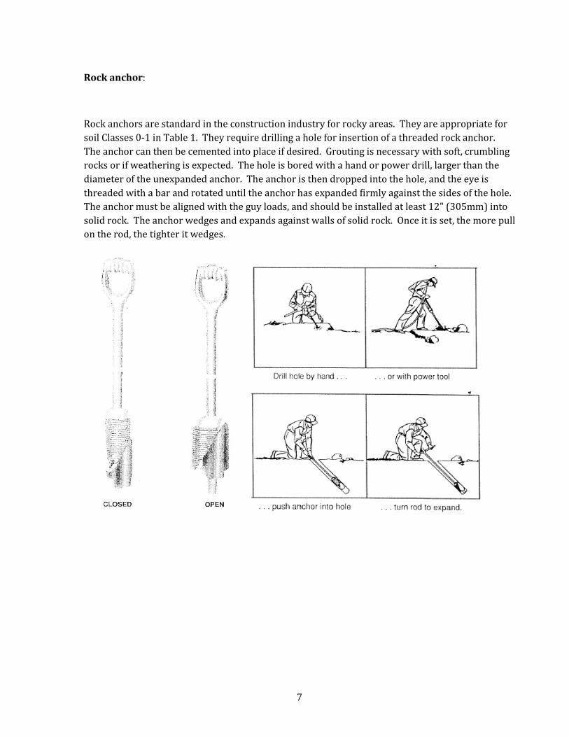
Rock anchor:
Rock anchors are standard in the construction industry for rocky areas. They are appropriate for
soil Classes 0-1 in Table 1. They require drilling a hole for insertion of a threaded rock anchor.
The anchor can then be cemented into place if desired. Grouting is necessary with soft, crumbling
rocks or if weathering is expected. The hole is bored with a hand or power drill, larger than the
diameter of the unexpanded anchor. The anchor is then dropped into the hole, and the eye is
threaded with a bar and rotated until the anchor has expanded firmly against the sides of the hole.
The anchor must be aligned with the guy loads, and should be installed at least 12" (305mm) into
solid rock. The anchor wedges and expands against walls of solid rock. Once it is set, the more pull
on the rod, the tighter it wedges.
8
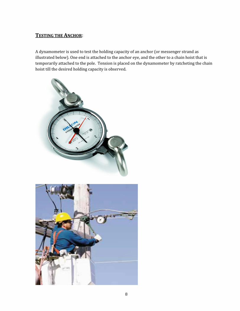
TESTING THE ANCHOR:
A dynamometer is used to test the holding capacity of an anchor (or messenger strand as
illustrated below). One end is attached to the anchor eye, and the other to a chain hoist that is
temporarily attached to the pole. Tension is placed on the dynamometer by ratcheting the chain
hoist till the desired holding capacity is observed.
9
CHAPTER 2 - BONDING AND GROUNDING
This document is intended to provide education on common Construction Practices for aerial construction of power and
telecommunications facilities. This is not an official codebook, nor should it be construed as a construction manual. When
constructing aerial facilities, please refer to the governing codes, such as the �ational Electrical Safety Code, �ational Electric
Code, Oregon Public Utility Commission Safety Rules, Oregon Occupational Safety And Health Administration, State, County
and Municipal codes, and all other applicable standards, including contracts.
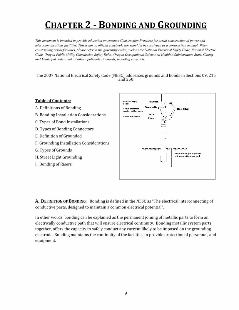
The 2007 National Electrical Safety Code (NESC) addresses grounds and bonds in Sections 09, 215 and 350
Table of Contents:
A. Definitions of Bonding
B. Bonding Installation Considerations
C. Types of Bond Installations
D. Types of Bonding Connectors
E. Definition of Grounded
F. Grounding Installation Considerations
G. Types of Grounds
H. Street Light Grounding
I. Bonding of Risers
A. DEFINITION OF BONDING: Bonding is defined in the NESC as “The electrical interconnecting of
conductive parts, designed to maintain a common electrical potential”.
In other words, bonding can be explained as the permanent joining of metallic parts to form an
electrically conductive path that will ensure electrical continuity. Bonding metallic system parts
together, offers the capacity to safely conduct any current likely to be imposed on the grounding
electrode. Bonding maintains the continuity of the facilities to provide protection of personnel, and
equipment.
10
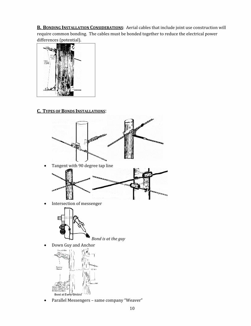
B. BONDING INSTALLATION CONSIDERATIONS: Aerial cables that include joint use construction will
require common bonding. The cables must be bonded together to reduce the electrical power
differences (potential).
C. TYPES OF BONDS INSTALLATIONS:
• Tangent with 90 degree tap line
• Intersection of messenger
Bond is at the guy
• Down Guy and Anchor
• Parallel Messengers – same company “Weaver”

11
D. TYPES OF BONDING CONNECTORS:
E. DEFINITION OF GROUNDED: Grounded is defined by the NESC as “Connected to or in contact
with earth or connected to some extended conductive body that serves instead of the earth.
In other words, facilities are grounded when they are purposefully connected by conductive parts
to a grounding electrode (ground rod) that is in direct contact with earth – preferably undisturbed.
Grounding of facilities is needed for the protection of personnel and facilities from errant electrical
faults.
F. GROUNDING INSTALLATION CONSIDERATIONS: The NESC 2007 code requires all joint utility
occupiers to ground whenever a vertical ground (pole ground) exists. It is then recommend
leaving clearance for other occupiers to attach to ground.
H-2 Connector (Fargo) C or D-Clamp Cable Lashing Clamp (Bug Nut)
B-Strand Clamp Ground Rod Clamp Ground Weaver
12
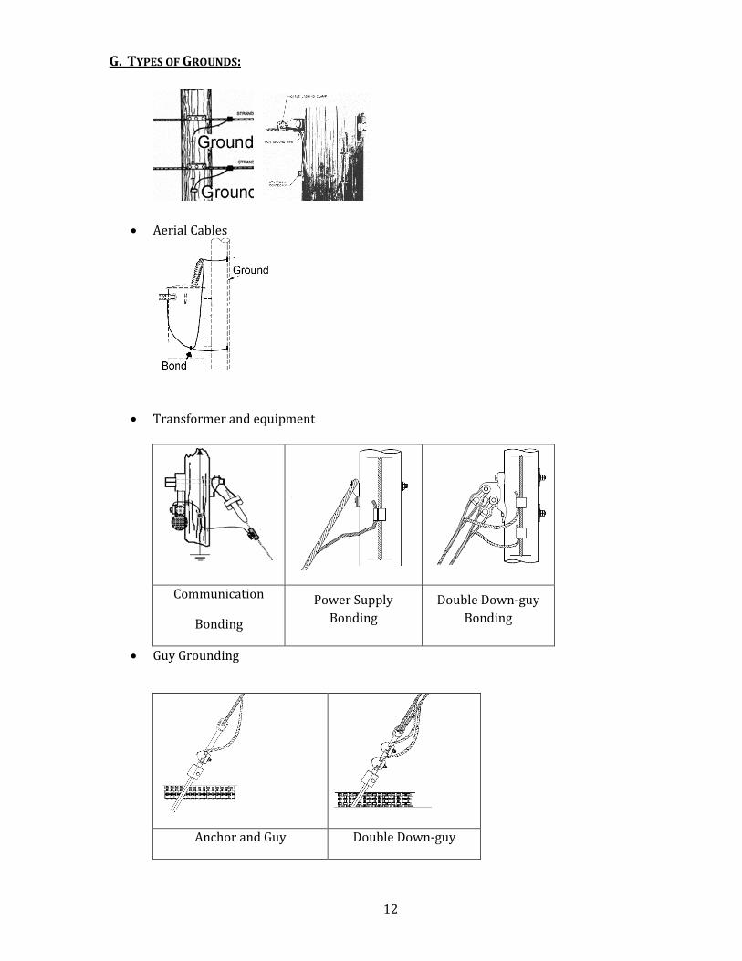
G. TYPES OF GROUNDS:
• Aerial Cables
• Transformer and equipment
Communication
Bonding
Power Supply
Bonding
Double Down-guy
Bonding
• Guy Grounding
Anchor and Guy Double Down-guy
13
G. Types of Grounds (cont):
• Anchor Grounding
Insulated Guy – Not
bonded
Insulated Guy 8 ft min.
above ground-Bonded
Porcelain Insulator or “Johnny
Ball”
• Guy Strain Insulator
Per NESC 279A, guys must be bonded unless guy insulator is used- then exceptions apply.
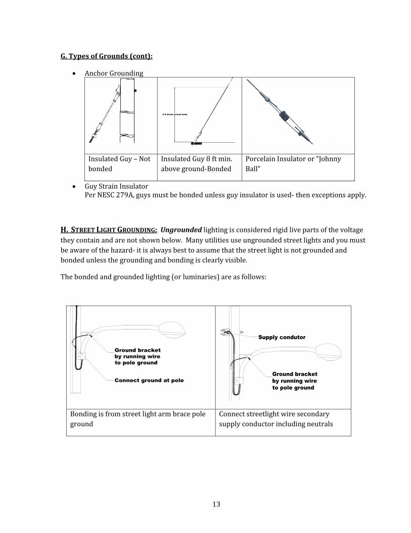
H. STREET LIGHT GROUNDING: Ungrounded lighting is considered rigid live parts of the voltage
they contain and are not shown below. Many utilities use ungrounded street lights and you must
be aware of the hazard- it is always best to assume that the street light is not grounded and
bonded unless the grounding and bonding is clearly visible.
The bonded and grounded lighting (or luminaries) are as follows:
Ground bracket
by running wire
to pole ground
Connect ground at pole
Ground bracket
by running wire
to pole ground
Supply condutor
Bonding is from street light arm brace pole
ground
Connect streetlight wire secondary
supply conductor including neutrals
14
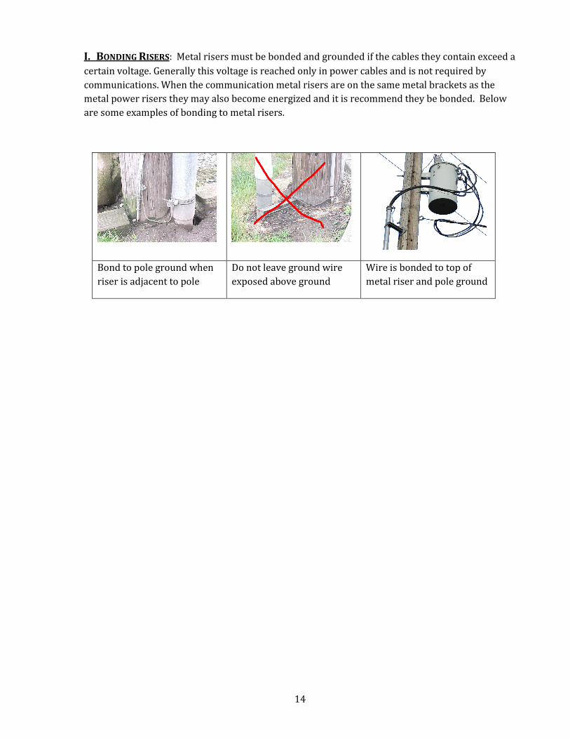
I. BONDING RISERS: Metal risers must be bonded and grounded if the cables they contain exceed a
certain voltage. Generally this voltage is reached only in power cables and is not required by
communications. When the communication metal risers are on the same metal brackets as the
metal power risers they may also become energized and it is recommend they be bonded. Below
are some examples of bonding to metal risers.
Bond to pole ground when
riser is adjacent to pole
Do not leave ground wire
exposed above ground
Wire is bonded to top of
metal riser and pole ground
15
CHAPTER 3 - FRAMING This document is intended to provide education on common Construction Practices for aerial construction of power and
telecommunications facilities. This is not an official codebook, nor should it be construed as a construction manual. When
constructing aerial facilities, please refer to the governing codes, such as the �ational Electrical Safety Code, �ational Electric
Code, Oregon Public Utility Commission Safety Rules, Oregon Occupational Safety And Health Administration, State, County
and Municipal codes, and all other applicable standards, including contracts.
The 2007 National Electrical Safety Code (NESC) addresses framing in sections 232, 235, 238
Table of Contents:
A. Definition of Framing
B. Site Specific Construction
C. Types of Framing
D. Avian Protection Construction
E. Construction Practices
F. Ground Clearances
G. Voltage Clearances
A. DEFINITION OF FRAMING: Framing is not defined in the NESC. In this document ‘Framing’ is
referring to the overhead installations of poles and some other utility structures such as
transmission H structures and the facilities attached to them. It is basically the construction style
that best suits certain conditions determined by generally accepted practices
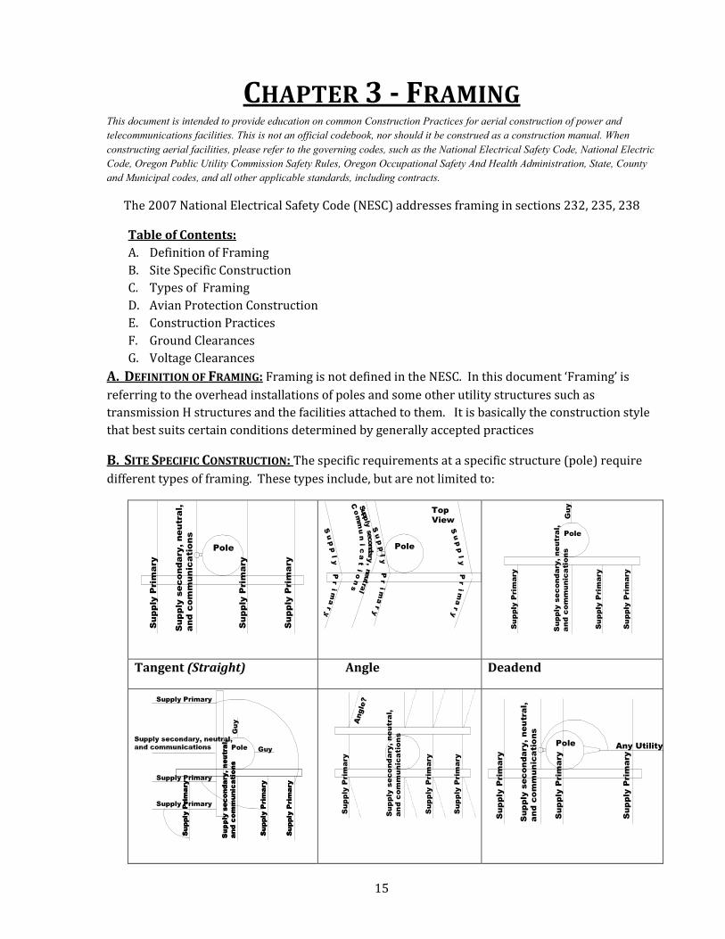
B. SITE SPECIFIC CONSTRUCTION: The specific requirements at a specific structure (pole) require
different types of framing. These types include, but are not limited to:
Pole
Supply Primary
Supply Primary
Supply Primary
Supply secondary, neutral,
and communications
Pole
Top
View
upply Primar
Supply Primary
Supply Primary
Supply secondary, neutra
l
Communications
Pole
Supply Primary
Supply Primary
Supply Primary
Supply secondary, neutral,
and communications
Guy
Tangent (Straight) Angle Deadend
Pole
Supply Primary
Supply Primary
Supply Primary
Supply secondary, neutral,
and communications
Guy
Supply Primary
Supply Primary
Supply Primary
Supply secondary, neutral,
and communications
Supply Primary
Supply Primary
Supply Primary
Guy
Supply Primary
Supply Primary
Supply Primary
Supply secondary, neutral,
and communications
Angle?
Pole
Supply Primary
Supply Primary
Supply Primary
Supply secondary, neutral,
and communications
Any Utility
16
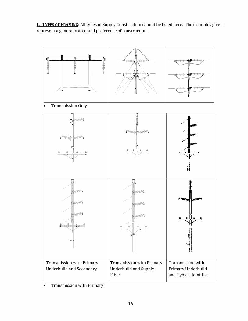
C. TYPES OF FRAMING: All types of Supply Construction cannot be listed here. The examples given
represent a generally accepted preference of construction.
• Transmission Only
Transmission with Primary
Underbuild and Secondary
Transmission with Primary
Underbuild and Supply
Fiber
Transmission with
Primary Underbuild
and Typical Joint Use
• Transmission with Primary
17
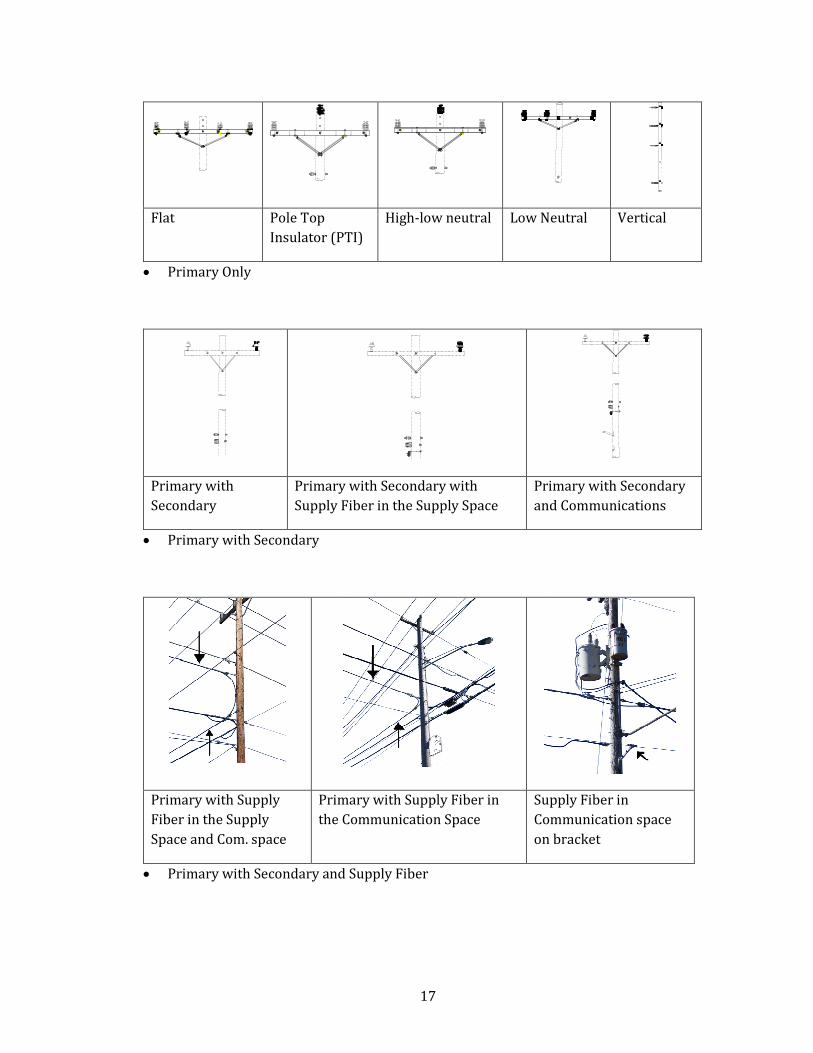
Flat Pole Top
Insulator (PTI)
High-low neutral Low Neutral Vertical
• Primary Only
Primary with
Secondary
Primary with Secondary with
Supply Fiber in the Supply Space
Primary with Secondary
and Communications
• Primary with Secondary
Primary with Supply
Fiber in the Supply
Space and Com. space
Primary with Supply Fiber in
the Communication Space
Supply Fiber in
Communication space
on bracket
• Primary with Secondary and Supply Fiber
18
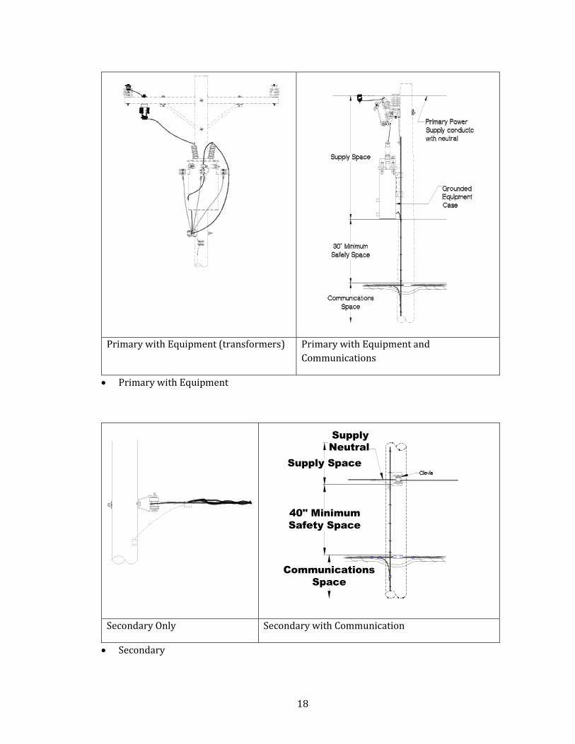
Primary with Equipment (transformers) Primary with Equipment and
Communications
• Primary with Equipment
40" Minimum
Safety Space
Supply Space
Communications
Space
Supply
Neutral
Secondary Only Secondary with Communication
• Secondary
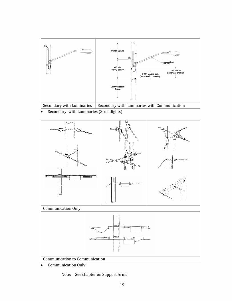
19
Secondary with Luminaries Secondary with Luminaries with Communication
• Secondary with Luminaries (Streetlights)
Communication Only
Communication to Communication
• Communication Only
Note: See chapter on Support Arms

20
D. AVIAN PROTECTION CONSTRUCTION: In recent years there has been a growing concern
regarding the protection of migratory birds. The U.S. department of Fish and Wildlife has required
many supply companies to provide an Avian Protection Plan. This plan may require greater
spread between conductors. The supply utility may lower the conductors to provide fowl
wingspread.
E. CONSTRUCTION PRACTICES: There are some generally accepted rules based on the NESC as to
where supply and communication attach to structures (poles). As with all construction, there are
exceptions.
Normally the attachments for new construction are from top to bottom as follows
• Supply Transmission
• Supply Primary - 10 ft minimum below Transmission
• Supply Secondary – 6 ft minimum below Primary
• Supply Fiber – can also be above secondary
• Communication TV – 40 inches below supply cables
• Communication Telco – 40 inches below supply cables and 12 inches below TV
• Communication to Communication 12 inch separation
Note: Suggested practice is to follow the existing framing for new attachments
and construction.
Example: If the existing neutral or communication aerial cable is on the road
side – new aerial cables should be installed on the road side.
F. GROUND CLEARANCES: Clearances of attachment heights vary, depending on the clearance of
the cable or conductor to ground. NESC table 232-1 gives detailed minimum ground clearances for
both supply and communications. However there are other jurisdictions that may require greater
heights.
Below is an example of road districts that require more than the minimum NESC code.
Minimum Clearances Over Road
Vert
Feet
State County
ODOT Coos Lane Lincoln Douglas
24
22
20
18
16
15½
12
11
8
3½
Crossing
Parallel
Sag-crossing
Communications
Clearances are
measured from surface
to surface
21
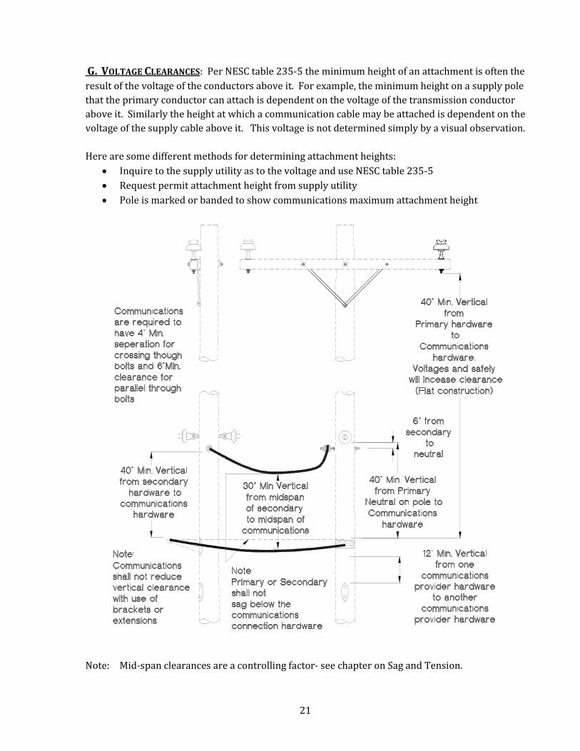
G. VOLTAGE CLEARANCES: Per NESC table 235-5 the minimum height of an attachment is often the
result of the voltage of the conductors above it. For example, the minimum height on a supply pole
that the primary conductor can attach is dependent on the voltage of the transmission conductor
above it. Similarly the height at which a communication cable may be attached is dependent on the
voltage of the supply cable above it. This voltage is not determined simply by a visual observation.
Here are some different methods for determining attachment heights:
• Inquire to the supply utility as to the voltage and use NESC table 235-5
• Request permit attachment height from supply utility
• Pole is marked or banded to show communications maximum attachment height
Note: Mid-span clearances are a controlling factor- see chapter on Sag and Tension.
22
CHAPTER 4 - POLES This document is intended to provide education on common Construction Practices for aerial construction of power and
telecommunications facilities. This is not an official codebook, nor should it be construed as a construction manual. When
constructing aerial facilities, please refer to the governing codes, such as the �ational Electrical Safety Code, �ational Electric
Code, Oregon Public Utility Commission Safety Rules, Oregon Occupational Safety And Health Administration, State, County
and Municipal codes, and all other applicable standards, including contracts.
The 2007 National Electrical Code (NESC) addresses poles throughout the code.
Table of contents:
A: Definition
B: Placement
C: Types
D: Identification
E: Grades of Construction
F: Pole Class
G: Pole Top Extension
H: Pole Supports
A. DEFINITION OF A POLE: NESC defines poles as “Structures used to support supply and or
communication conductor cables and associated equipment”.
B. PLACEMENT: The placement of poles is subject to numerous conditions, such as the general
location and proximity to the street, buildings, fire hydrants, driveways or easements and other
aerial or buried utilities. Additional factors to consider are the weight loading for the pole, the
depth the pole is to be set, protective barriers that may be needed, foliage in the vicinity that may
need to be trimmed, and local climate (snow and or wind loads). As with any excavation, utility
locates must be made.
C. TYPES:
•••• Wood: The most predominate species of wood used for poles consists of Western
Red Cedar, Douglas Fir, various species of Pine and Western Larch. Typically wood
poles are treated to prevent deterioration and rot; common treatments can be
Copper Naphthenate or Pentachloraphenol. The species of wood and the treatment
used can usually be found on the brand or tag that the supplier places on the pole.
•••• Metal: Tubular metal poles are typically made from galvanized steel or aluminum
•••• Concrete: Designs for concrete poles include tapered structures and round poles
made of
o Solid Concrete
o Pre-Stressed Concrete
o Hybrid – Concrete and Steel Poles
•••• Fiberglass: Poles are hollow and similar to the tubular metal poles with a typical
fiberglass thicknesses of ¼ to ½-inch
23
•••• Laminate: An Engineered product comprised of assemblies of specifically selected
and prepared wood laminates bonded with adhesives and treated with
preservatives.
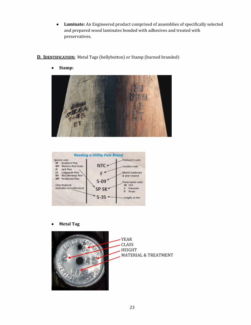
D. IDENTIFICATION: Metal Tags (bellybutton) or Stamp (burned branded)
•••• Stamp:
•••• Metal Tag
YEAR
CLASS
HEIGHT MATERIAL & TREATMENT
24
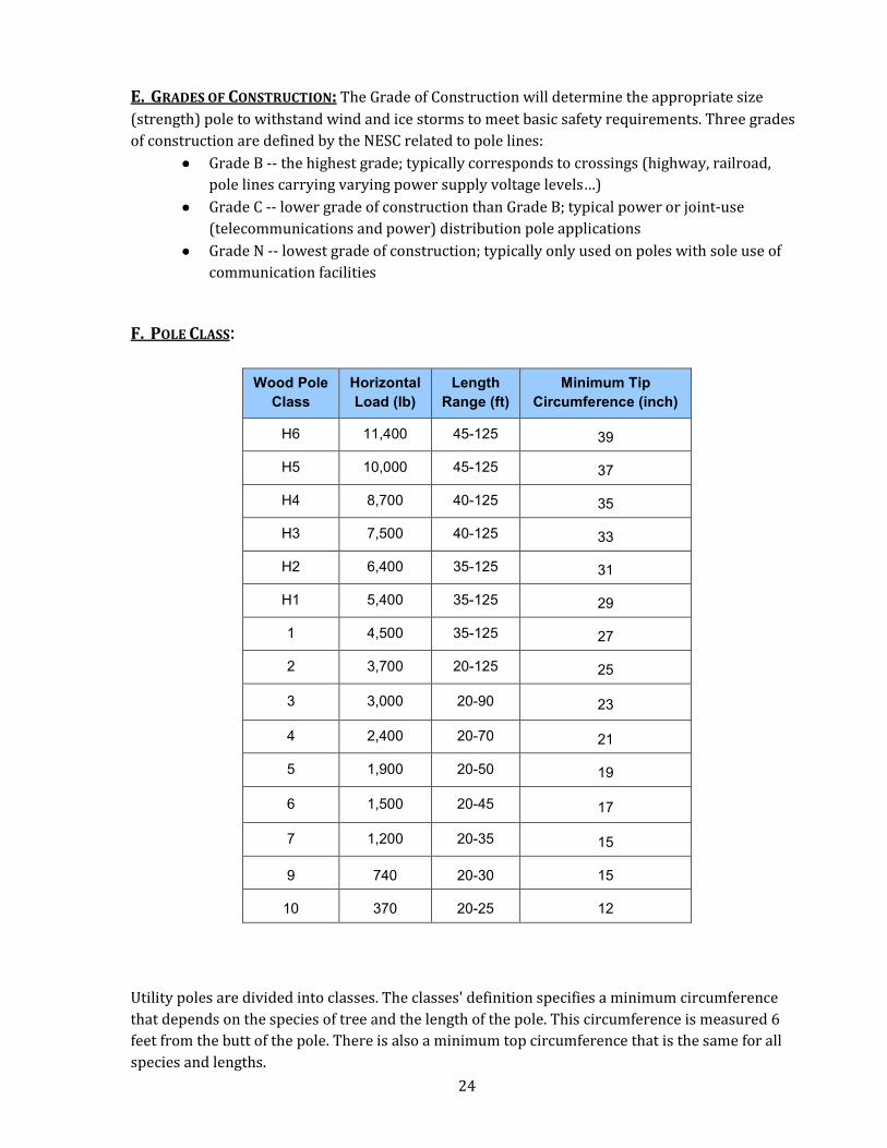
E. GRADES OF CONSTRUCTION: The Grade of Construction will determine the appropriate size
(strength) pole to withstand wind and ice storms to meet basic safety requirements. Three grades
of construction are defined by the NESC related to pole lines:
•••• Grade B -- the highest grade; typically corresponds to crossings (highway, railroad,
pole lines carrying varying power supply voltage levels…)
•••• Grade C -- lower grade of construction than Grade B; typical power or joint-use
(telecommunications and power) distribution pole applications
•••• Grade N -- lowest grade of construction; typically only used on poles with sole use of
communication facilities
F. POLE CLASS:
Wood Pole
Class
Horizontal
Load (lb)
Length
Range (ft)
Minimum Tip
Circumference (inch)
H6 11,400 45-125 39
H5 10,000 45-125 37
H4 8,700 40-125 35
H3 7,500 40-125 33
H2 6,400 35-125 31
H1 5,400 35-125 29
1 4,500 35-125 27
2 3,700 20-125 25
3 3,000 20-90 23
4 2,400 20-70 21
5 1,900 20-50 19
6 1,500 20-45 17
7 1,200 20-35 15
9 740 20-30 15
10 370 20-25 12
Utility poles are divided into classes. The classes' definition specifies a minimum circumference
that depends on the species of tree and the length of the pole. This circumference is measured 6
feet from the butt of the pole. There is also a minimum top circumference that is the same for all
species and lengths.
25
For example, a class 1 pole has a minimum top circumference of 27 inches. If it is 25 feet long and
cedar (most utility poles are cedar), the circumference measured 6 feet from the bottom must be at
least 43.5 inches.
The higher the class number, the skinnier the pole. Pole lengths start at 16 feet and increase by 2-
foot steps to 22 feet, then by fives from 25 feet to 90 feet. A 90-foot class 1 western red cedar pole
weighs about 6,600 pounds. A 16-foot pole weighs only about 700.
Standards (from ANSI) severely limit or exclude various types of damage, including bird holes and
insect boring, and describe ways of specifying the pole's straightness.
On curves, hillsides, or other locations where there's an unbalanced pull on the pole, standard
practice calls for increasing the portion of the pole that is buried. For example, for poles being set
along a straight line, 6 feet of a 35-foot pole would be buried, but if the pole were on a curve, 6.5
feet.
A 35-foot pole is a typical length used in cities to carry one or two crossarms. Poles are spaced
about 100 feet to 150 feet apart, with 125 feet being typical.
The class of the pole should not be confused with the grade of construction.
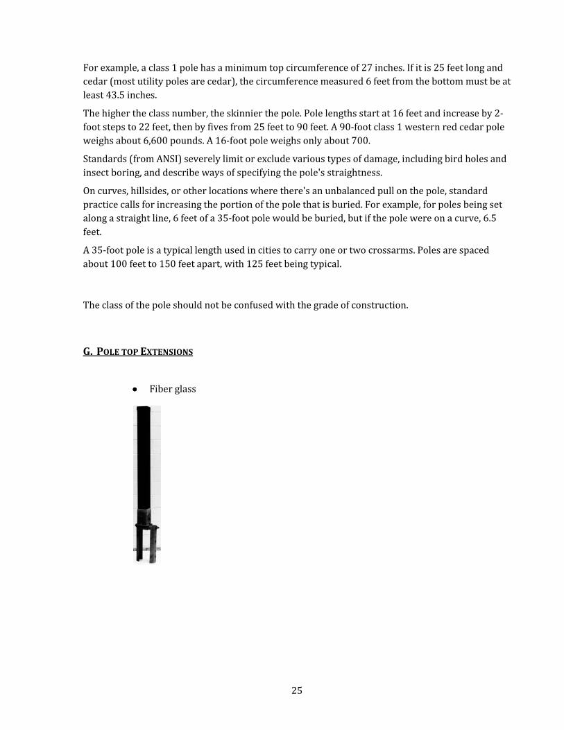
G. POLE TOP EXTENSIONS
•••• Fiber glass
26
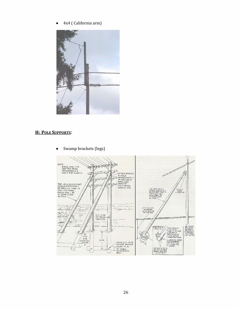
•••• 4x4 ( California arm)
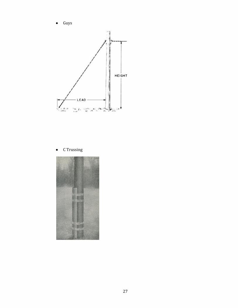
H: POLE SUPPORTS:
•••• Swamp brackets (legs)
27
•••• Guys
•••• C Trussing
28
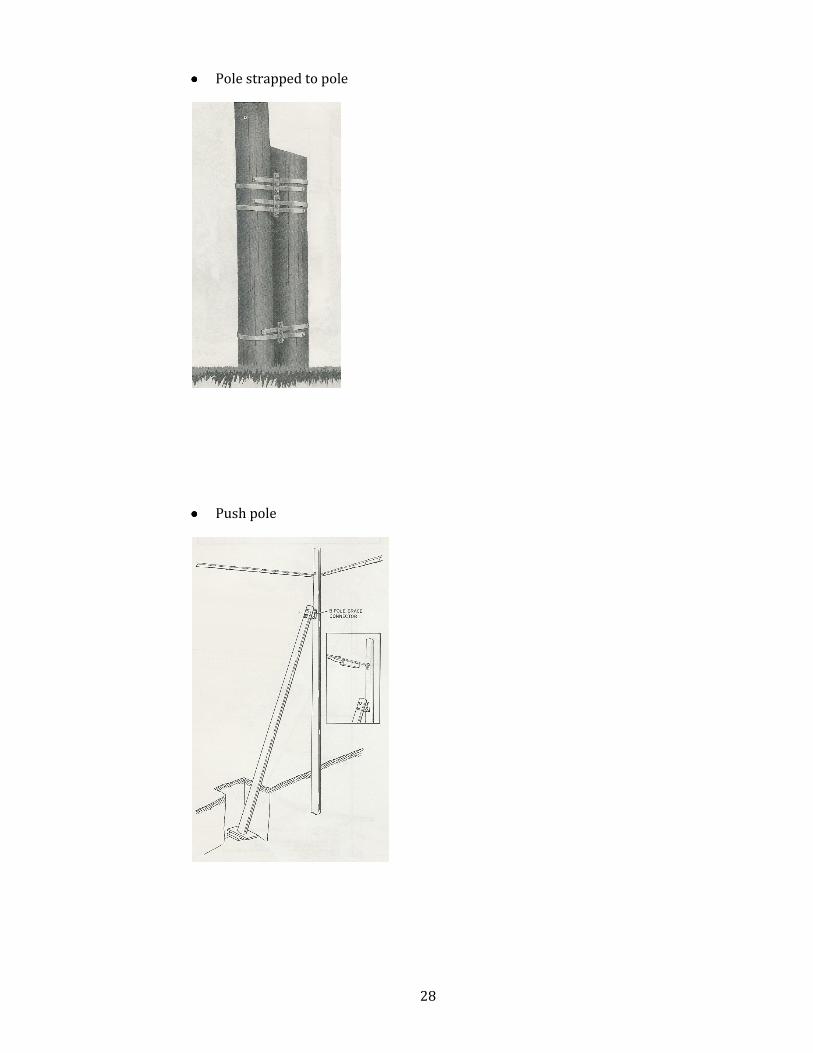
•••• Pole strapped to pole
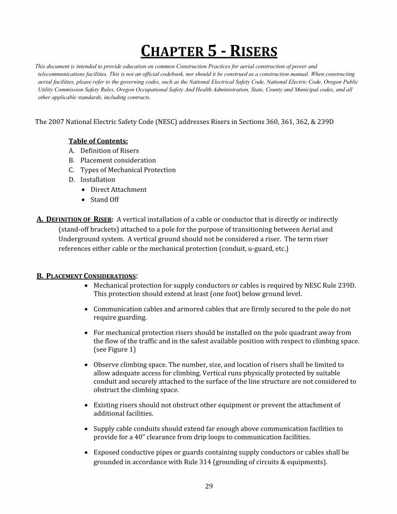
•••• Push pole
29
CHAPTER 5 - RISERS This document is intended to provide education on common Construction Practices for aerial construction of power and
telecommunications facilities. This is not an official codebook, nor should it be construed as a construction manual. When constructing
aerial facilities, please refer to the governing codes, such as the �ational Electrical Safety Code, �ational Electric Code, Oregon Public
Utility Commission Safety Rules, Oregon Occupational Safety And Health Administration, State, County and Municipal codes, and all
other applicable standards, including contracts.
The 2007 National Electric Safety Code (NESC) addresses Risers in Sections 360, 361, 362, & 239D
Table of Contents:
A. Definition of Risers
B. Placement consideration
C. Types of Mechanical Protection
D. Installation
• Direct Attachment
• Stand Off
A. DEFINITION OF RISER: A vertical installation of a cable or conductor that is directly or indirectly
(stand-off brackets) attached to a pole for the purpose of transitioning between Aerial and
Underground system. A vertical ground should not be considered a riser. The term riser
references either cable or the mechanical protection (conduit, u-guard, etc.)
B. PLACEMENT CONSIDERATIONS: • Mechanical protection for supply conductors or cables is required by NESC Rule 239D.
This protection should extend at least (one foot) below ground level.
• Communication cables and armored cables that are firmly secured to the pole do not
require guarding.
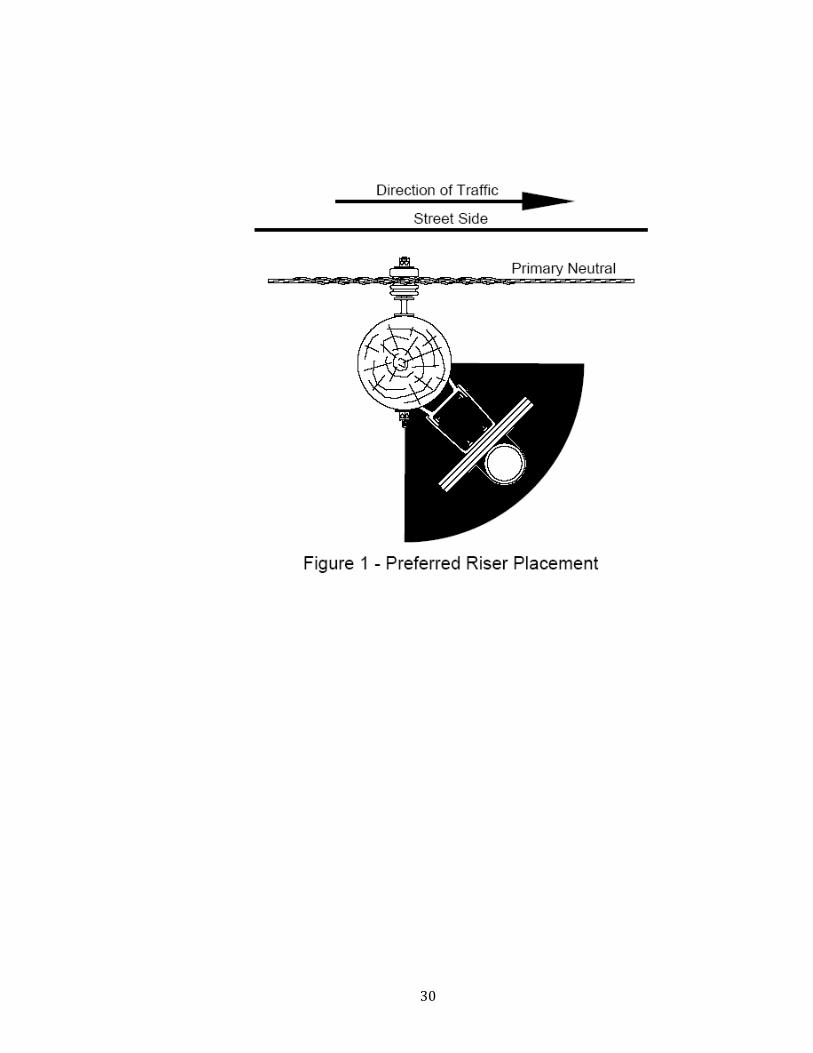
• For mechanical protection risers should be installed on the pole quadrant away from
the flow of the traffic and in the safest available position with respect to climbing space.
(see Figure 1)
• Observe climbing space. The number, size, and location of risers shall be limited to
allow adequate access for climbing. Vertical runs physically protected by suitable
conduit and securely attached to the surface of the line structure are not considered to
obstruct the climbing space.
• Existing risers should not obstruct other equipment or prevent the attachment of
additional facilities.
• Supply cable conduits should extend far enough above communication facilities to
provide for a 40” clearance from drip loops to communication facilities.
• Exposed conductive pipes or guards containing supply conductors or cables shall be
grounded in accordance with Rule 314 (grounding of circuits & equipments).
30
31
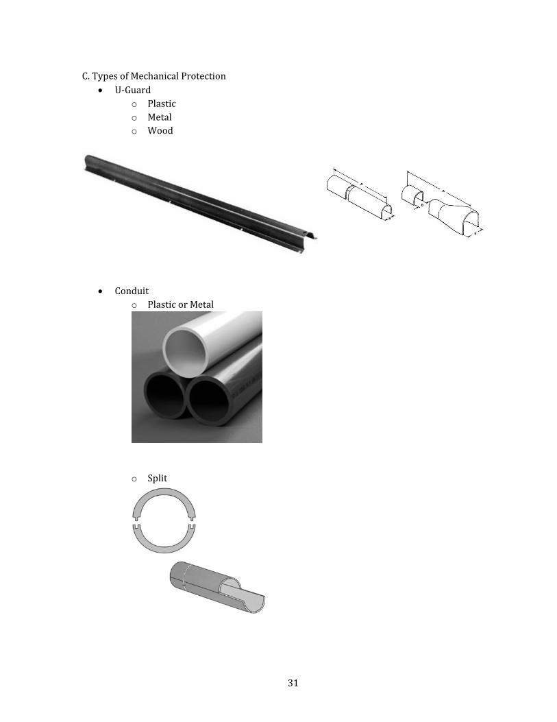
C. Types of Mechanical Protection
• U-Guard
o Plastic
o Metal
o Wood
• Conduit
o Plastic or Metal
o Split
32
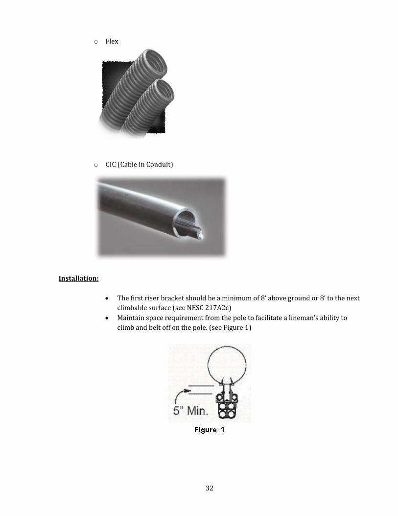
o Flex
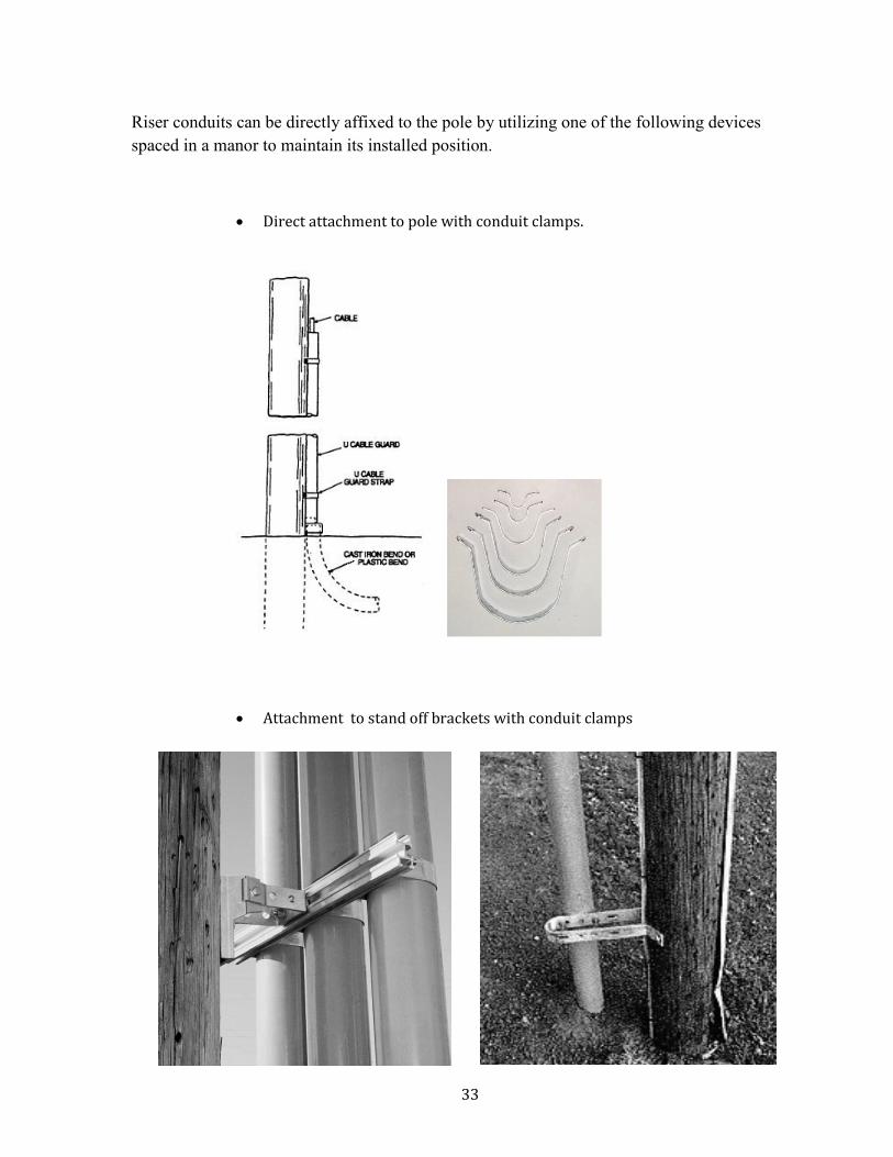
o CIC (Cable in Conduit)
Installation:
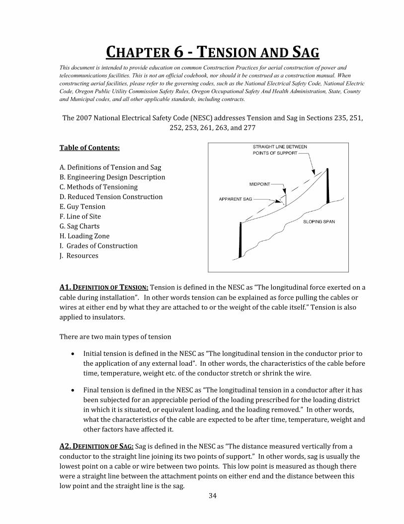
• The first riser bracket should be a minimum of 8’ above ground or 8’ to the next
climbable surface (see NESC 217A2c)
• Maintain space requirement from the pole to facilitate a lineman’s ability to
climb and belt off on the pole. (see Figure 1)
33
Riser conduits can be directly affixed to the pole by utilizing one of the following devices
spaced in a manor to maintain its installed position.
• Direct attachment to pole with conduit clamps.
• Attachment to stand off brackets with conduit clamps
34
CHAPTER 6 - TENSION AND SAG This document is intended to provide education on common Construction Practices for aerial construction of power and
telecommunications facilities. This is not an official codebook, nor should it be construed as a construction manual. When
constructing aerial facilities, please refer to the governing codes, such as the �ational Electrical Safety Code, �ational Electric
Code, Oregon Public Utility Commission Safety Rules, Oregon Occupational Safety And Health Administration, State, County
and Municipal codes, and all other applicable standards, including contracts.
The 2007 National Electrical Safety Code (NESC) addresses Tension and Sag in Sections 235, 251,
252, 253, 261, 263, and 277
Table of Contents:
A. Definitions of Tension and Sag
B. Engineering Design Description
C. Methods of Tensioning
D. Reduced Tension Construction
E. Guy Tension
F. Line of Site
G. Sag Charts
H. Loading Zone
I. Grades of Construction
J. Resources
A1. DEFINITION OF TENSION: Tension is defined in the NESC as “The longitudinal force exerted on a
cable during installation”. In other words tension can be explained as force pulling the cables or
wires at either end by what they are attached to or the weight of the cable itself.” Tension is also
applied to insulators.
There are two main types of tension
• Initial tension is defined in the NESC as “The longitudinal tension in the conductor prior to
the application of any external load”. In other words, the characteristics of the cable before
time, temperature, weight etc. of the conductor stretch or shrink the wire.
• Final tension is defined in the NESC as “The longitudinal tension in a conductor after it has
been subjected for an appreciable period of the loading prescribed for the loading district
in which it is situated, or equivalent loading, and the loading removed.” In other words,
what the characteristics of the cable are expected to be after time, temperature, weight and
other factors have affected it.
A2. DEFINITION OF SAG: Sag is defined in the NESC as “The distance measured vertically from a
conductor to the straight line joining its two points of support.” In other words, sag is usually the
lowest point on a cable or wire between two points. This low point is measured as though there
were a straight line between the attachment points on either end and the distance between this
low point and the straight line is the sag.
35
B. ENGINEERING DESIGN: The appropriate sag and tension is determined by
• Span lengths
• Strand size
• Load
• Storm loading area
• Temperature
• Vertical clearances above grade
• Vertical clearances from other utilities
• Pole lengths
• Class of pole
C. METHODS OF TENSIONING:
Types of Tensioning
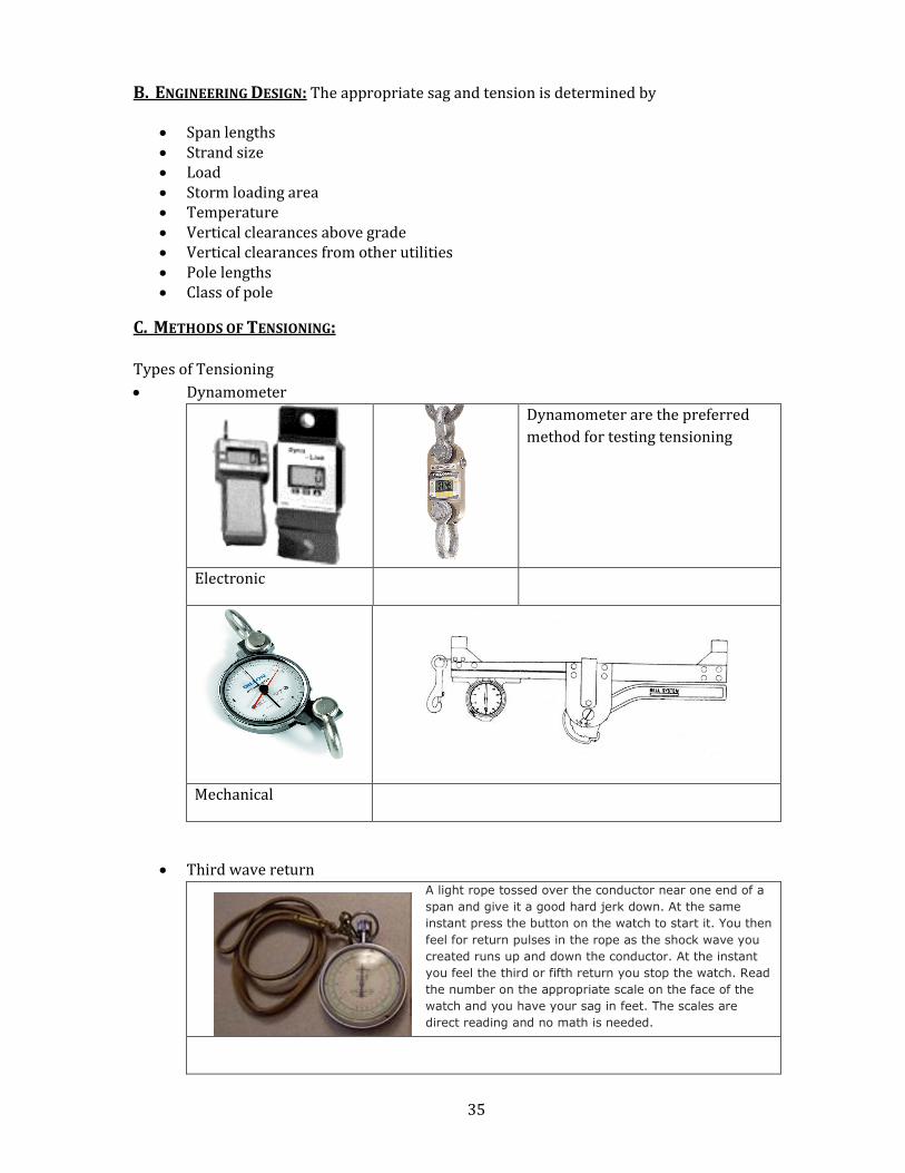
• Dynamometer
Dynamometer are the preferred
method for testing tensioning
Electronic
Mechanical
• Third wave return
A light rope tossed over the conductor near one end of a
span and give it a good hard jerk down. At the same
instant press the button on the watch to start it. You then
feel for return pulses in the rope as the shock wave you
created runs up and down the conductor. At the instant
you feel the third or fifth return you stop the watch. Read
the number on the appropriate scale on the face of the
watch and you have your sag in feet. The scales are
direct reading and no math is needed.
36
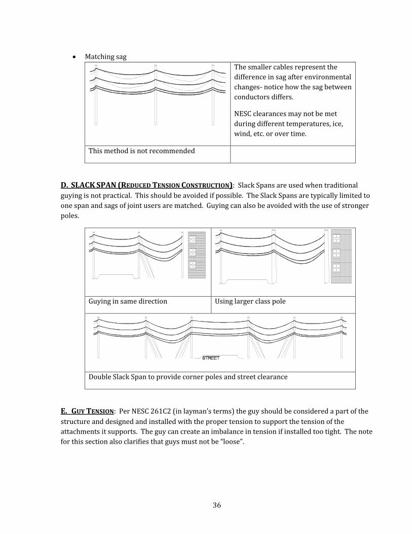
• Matching sag
The smaller cables represent the
difference in sag after environmental
changes- notice how the sag between
conductors differs.
NESC clearances may not be met
during different temperatures, ice,
wind, etc. or over time.
This method is not recommended
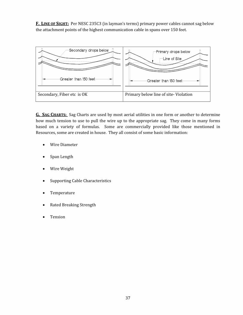
D. SLACK SPAN (REDUCED TENSION CONSTRUCTION): Slack Spans are used when traditional
guying is not practical. This should be avoided if possible. The Slack Spans are typically limited to
one span and sags of joint users are matched. Guying can also be avoided with the use of stronger
poles.
Guying in same direction Using larger class pole
Double Slack Span to provide corner poles and street clearance
E. GUY TENSION: Per NESC 261C2 (in layman’s terms) the guy should be considered a part of the
structure and designed and installed with the proper tension to support the tension of the
attachments it supports. The guy can create an imbalance in tension if installed too tight. The note
for this section also clarifies that guys must not be “loose”.
37
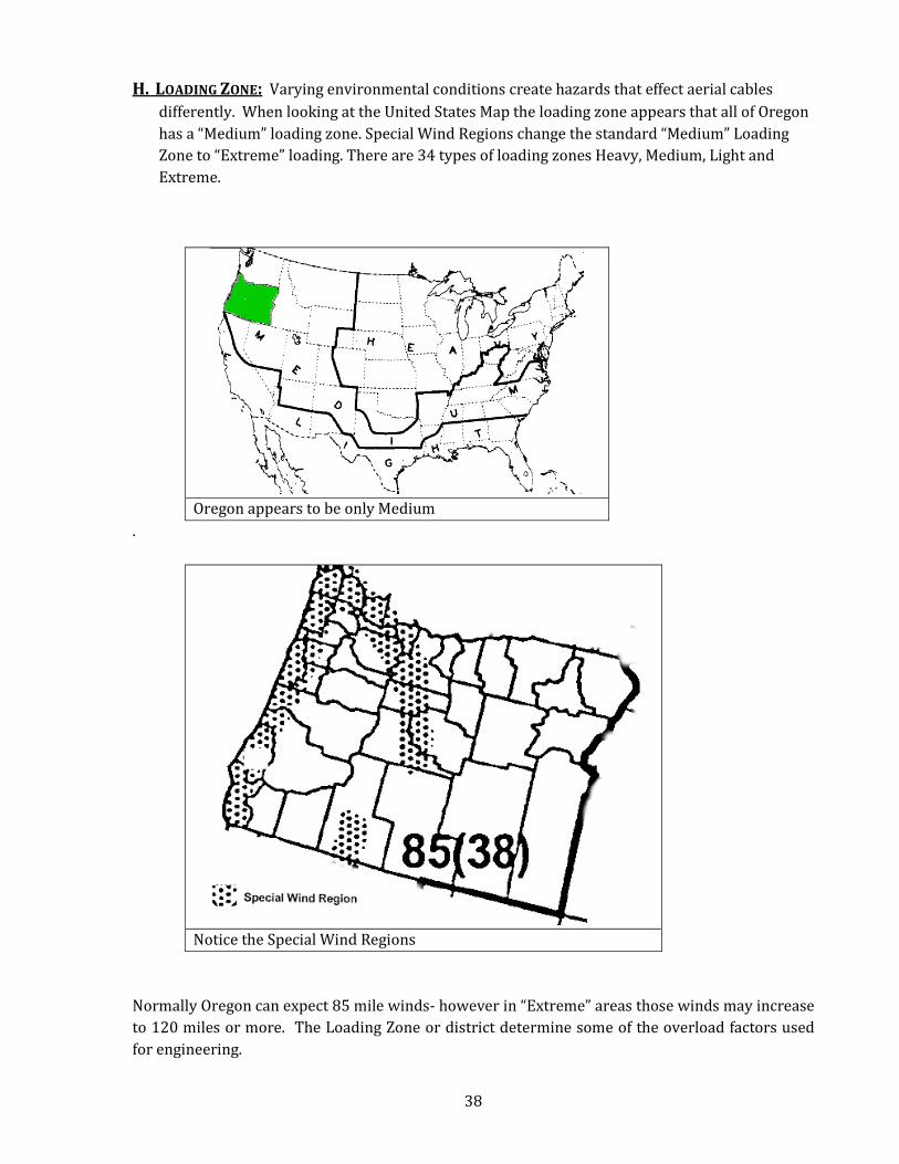
F. LINE OF SIGHT: Per NESC 235C3 (in layman’s terms) primary power cables cannot sag below
the attachment points of the highest communication cable in spans over 150 feet.
Secondary, Fiber etc is OK Primary below line of site- Violation
G. SAG CHARTS: Sag Charts are used by most aerial utilities in one form or another to determine
how much tension to use to pull the wire up to the appropriate sag. They come in many forms
based on a variety of formulas. Some are commercially provided like those mentioned in
Resources, some are created in house. They all consist of some basic information:
• Wire Diameter
• Span Length
• Wire Weight
• Supporting Cable Characteristics
• Temperature
• Rated Breaking Strength
• Tension
38
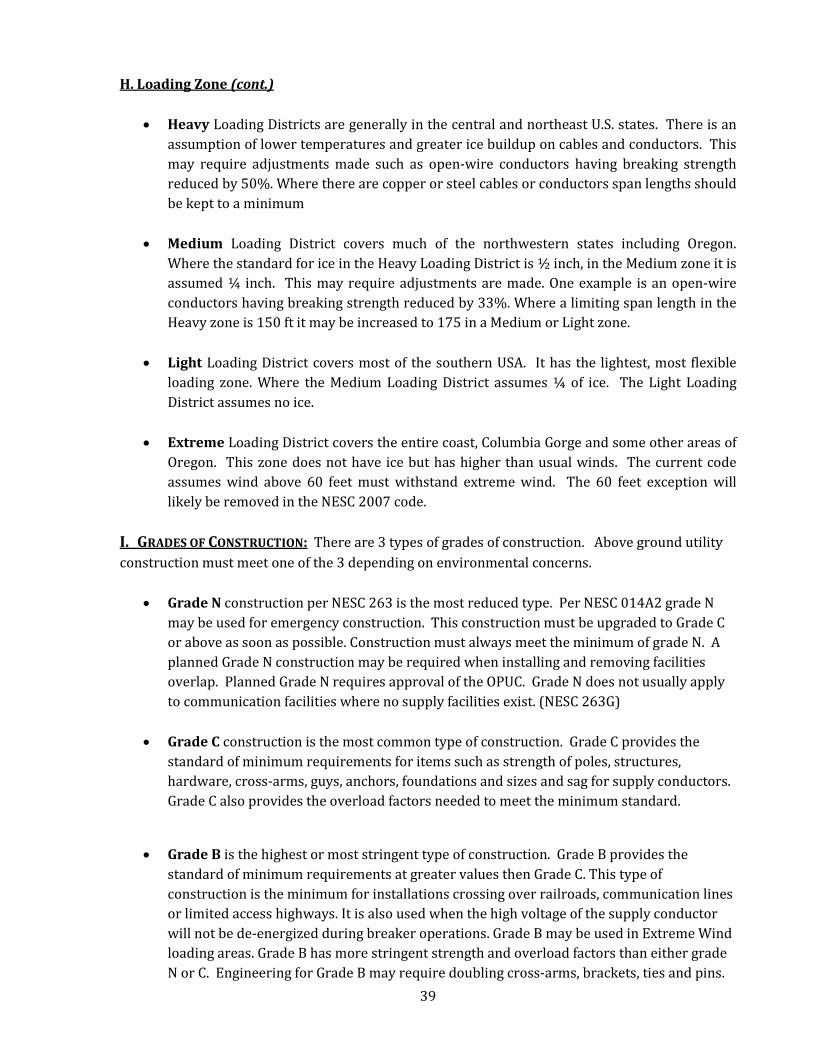
H. LOADING ZONE: Varying environmental conditions create hazards that effect aerial cables
differently. When looking at the United States Map the loading zone appears that all of Oregon
has a “Medium” loading zone. Special Wind Regions change the standard “Medium” Loading
Zone to “Extreme” loading. There are 34 types of loading zones Heavy, Medium, Light and
Extreme.
Oregon appears to be only Medium
.
Notice the Special Wind Regions
Normally Oregon can expect 85 mile winds- however in “Extreme” areas those winds may increase
to 120 miles or more. The Loading Zone or district determine some of the overload factors used
for engineering.
39
H. Loading Zone (cont.)
• Heavy Loading Districts are generally in the central and northeast U.S. states. There is an
assumption of lower temperatures and greater ice buildup on cables and conductors. This
may require adjustments made such as open-wire conductors having breaking strength
reduced by 50%. Where there are copper or steel cables or conductors span lengths should
be kept to a minimum
• Medium Loading District covers much of the northwestern states including Oregon.
Where the standard for ice in the Heavy Loading District is ½ inch, in the Medium zone it is
assumed ¼ inch. This may require adjustments are made. One example is an open-wire
conductors having breaking strength reduced by 33%. Where a limiting span length in the
Heavy zone is 150 ft it may be increased to 175 in a Medium or Light zone.
• Light Loading District covers most of the southern USA. It has the lightest, most flexible
loading zone. Where the Medium Loading District assumes ¼ of ice. The Light Loading
District assumes no ice.
• Extreme Loading District covers the entire coast, Columbia Gorge and some other areas of
Oregon. This zone does not have ice but has higher than usual winds. The current code
assumes wind above 60 feet must withstand extreme wind. The 60 feet exception will
likely be removed in the NESC 2007 code.
I. GRADES OF CONSTRUCTION: There are 3 types of grades of construction. Above ground utility
construction must meet one of the 3 depending on environmental concerns.
• Grade N construction per NESC 263 is the most reduced type. Per NESC 014A2 grade N
may be used for emergency construction. This construction must be upgraded to Grade C
or above as soon as possible. Construction must always meet the minimum of grade N. A
planned Grade N construction may be required when installing and removing facilities
overlap. Planned Grade N requires approval of the OPUC. Grade N does not usually apply
to communication facilities where no supply facilities exist. (NESC 263G)
• Grade C construction is the most common type of construction. Grade C provides the
standard of minimum requirements for items such as strength of poles, structures,
hardware, cross-arms, guys, anchors, foundations and sizes and sag for supply conductors.
Grade C also provides the overload factors needed to meet the minimum standard.
• Grade B is the highest or most stringent type of construction. Grade B provides the
standard of minimum requirements at greater values then Grade C. This type of
construction is the minimum for installations crossing over railroads, communication lines
or limited access highways. It is also used when the high voltage of the supply conductor
will not be de-energized during breaker operations. Grade B may be used in Extreme Wind
loading areas. Grade B has more stringent strength and overload factors than either grade
N or C. Engineering for Grade B may require doubling cross-arms, brackets, ties and pins.

40
J. RESOURCES:
• Alcoa Sag 10 (Supply Cables)
• CommScope (Communication Cables)
• NESC 2007
41
CHAPTER 7 - SUPPORT ARMS This document is intended to provide education on common Construction Practices for aerial construction of power and
telecommunications facilities. This is not an official codebook, nor should it be construed as a construction manual. When
constructing aerial facilities, please refer to the governing codes, such as the �ational Electrical Safety Code, �ational Electric
Code, Oregon Public Utility Commission Safety Rules, Oregon Occupational Safety And Health Administration, State, County
and Municipal codes, and all other applicable standards, including contracts.
*The 2007 National Electrical Safety Code (NESC) addresses Support Arms in Sections 232B, 243B;
72, 160
Table of Contents:
A. Definition of Support Arm
B. Placement considerations
C. Types
D. Braces
E. Lengths
F. Pole Gains
G. Installation
A. DEFINITION OF SUPPORT ARM: Apparatus made of wood (which may require bracing),
fiberglass, or steel that is bolted directly to the pole for the purpose of attaching equipment,
messengers or conductors.
• Establish or maintain clearances • Maintain the lead or tangent (eliminate the necessity to guy a pole) • Create space to accommodate multiple attachments • Create climbing space
B. PLACEMENT CONSIDERATIONS: Considerations include length, weight of facilities, angle, type of
arm, clearance from the pole and ground, space on the pole, and size of the arm.
(Note: Communication operators typically will not place a support guy on a support arm)

42
C. TYPES:
• Metallic communication alley arm
• Seattle bracket (extension bracket)
43
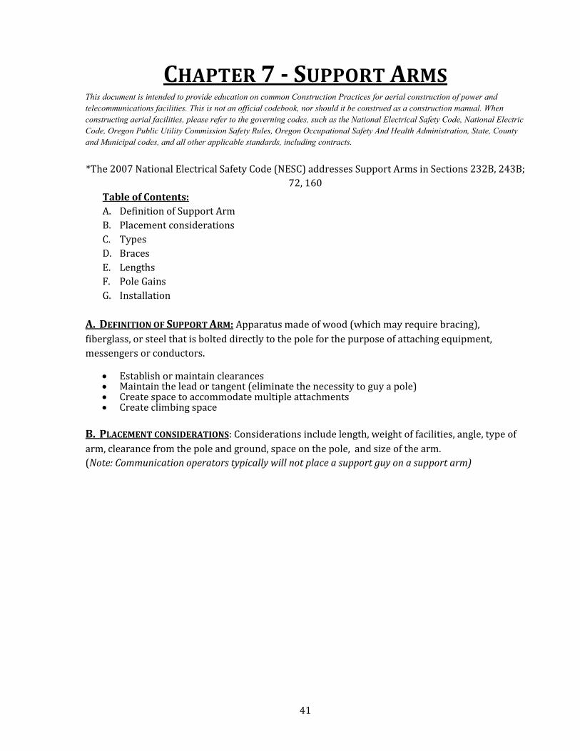
• T-alley bracket
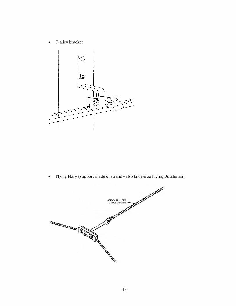
• Flying Mary (support made of strand - also known as Flying Dutchman)
44
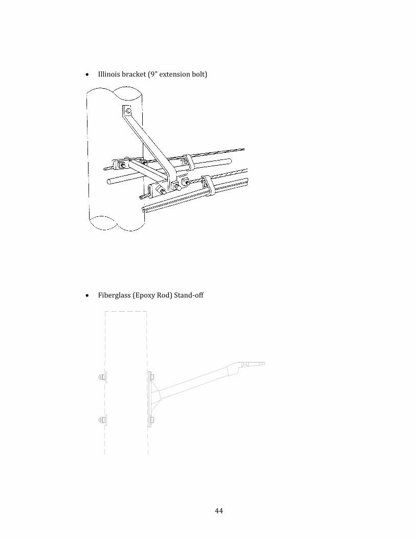
• Illinois bracket (9" extension bolt)
• Fiberglass (Epoxy Rod) Stand-off
45
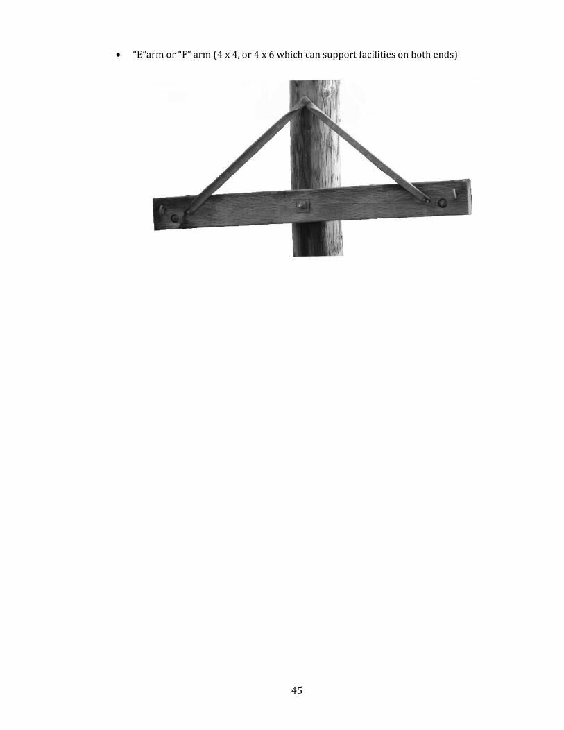
• “E”arm or “F” arm (4 x 4, or 4 x 6 which can support facilities on both ends)
46
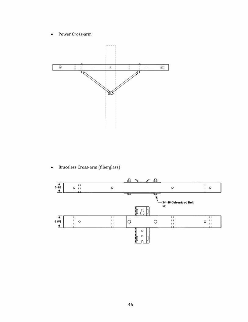
• Power Cross-arm
• Braceless Cross-arm (fiberglass)

47
• Wood cross arm / Alley arm (can support facilities on one end)
• Double arms
48
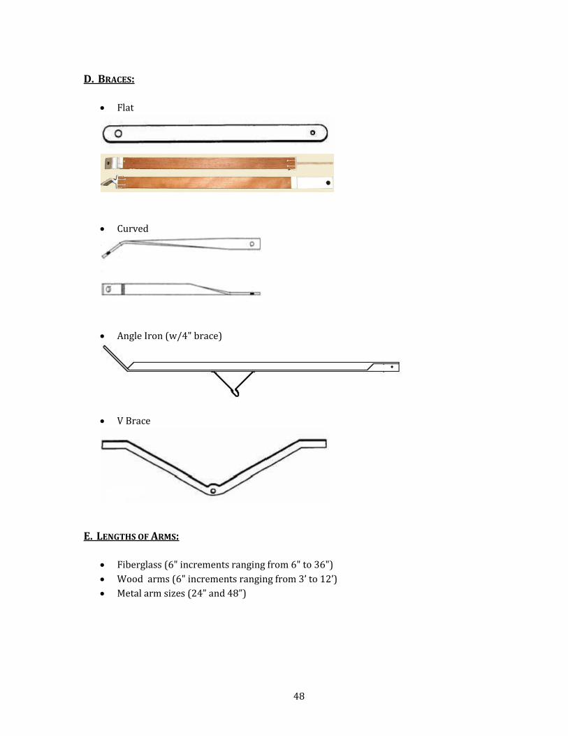
D. BRACES:
• Flat
• Curved
• Angle Iron (w/4" brace)
• V Brace
E. LENGTHS OF ARMS:
• Fiberglass (6" increments ranging from 6" to 36")
• Wood arms (6" increments ranging from 3’ to 12’)
• Metal arm sizes (24” and 48”)
49
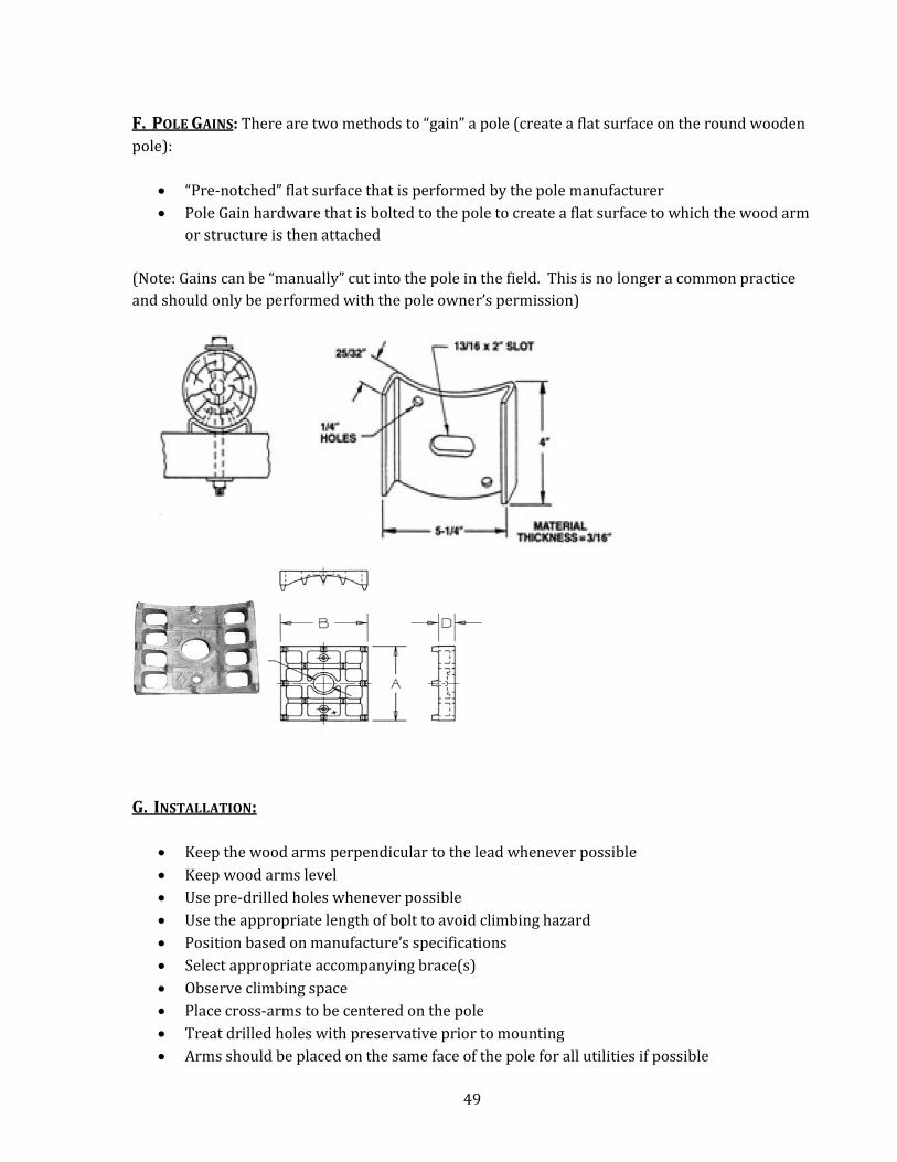
F. POLE GAINS: There are two methods to “gain” a pole (create a flat surface on the round wooden
pole):
• “Pre-notched” flat surface that is performed by the pole manufacturer
• Pole Gain hardware that is bolted to the pole to create a flat surface to which the wood arm
or structure is then attached
(Note: Gains can be “manually” cut into the pole in the field. This is no longer a common practice
and should only be performed with the pole owner’s permission)
G. INSTALLATION:
• Keep the wood arms perpendicular to the lead whenever possible
• Keep wood arms level
• Use pre-drilled holes whenever possible
• Use the appropriate length of bolt to avoid climbing hazard
• Position based on manufacture’s specifications
• Select appropriate accompanying brace(s)
• Observe climbing space
• Place cross-arms to be centered on the pole
• Treat drilled holes with preservative prior to mounting
• Arms should be placed on the same face of the pole for all utilities if possible
50
CHAPTER 8 - EQUIPMENT PICTORIAL This document is intended to provide education on common Construction Practices for aerial construction of power and
telecommunications facilities. This is not an official codebook, nor should it be construed as a construction manual. When
constructing aerial facilities, please refer to the governing codes, such as the �ational Electrical Safety Code, �ational Electric
Code, Oregon Public Utility Commission Safety Rules, Oregon Occupational Safety And Health Administration, State, County
and Municipal codes, and all other applicable standards, including contracts.
The 2007 National Electrical Safety Code (NESC) addresses equipment in section 38
Table of Contents:
A. Definition of Equipment
B. General Equipment
C. Supply Equipment (Power)
D. Telco Equipment
E. Cable Equipment
F. Fiber Equipment
G. Wireless Equipment
A. DEFINITION OF EQUIPMENT: Equipment is defined in the NESC as “A general term including
fittings, devices, appliances, fixtures, apparatus, and similar terms used as part of or in connection
with an electric supply or communications system”. In this section, Equipment is used to define a
common language for the different parts of the aerial utilities facilities on poles, structures and
towers, and shows the OJUA accepted abbreviations.
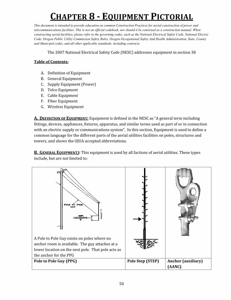
B. GENERAL EQUIPMENT): This equipment is used by all factions of aerial utilities. These types
include, but are not limited to:
A Pole to Pole Guy exists on poles where no
anchor room is available. The guy attaches at a
lower location on the next pole. That pole acts as
the anchor for the PPG
Pole to Pole Guy (PPG) Pole Step (STEP) Anchor (auxiliary)
(AANC)
51
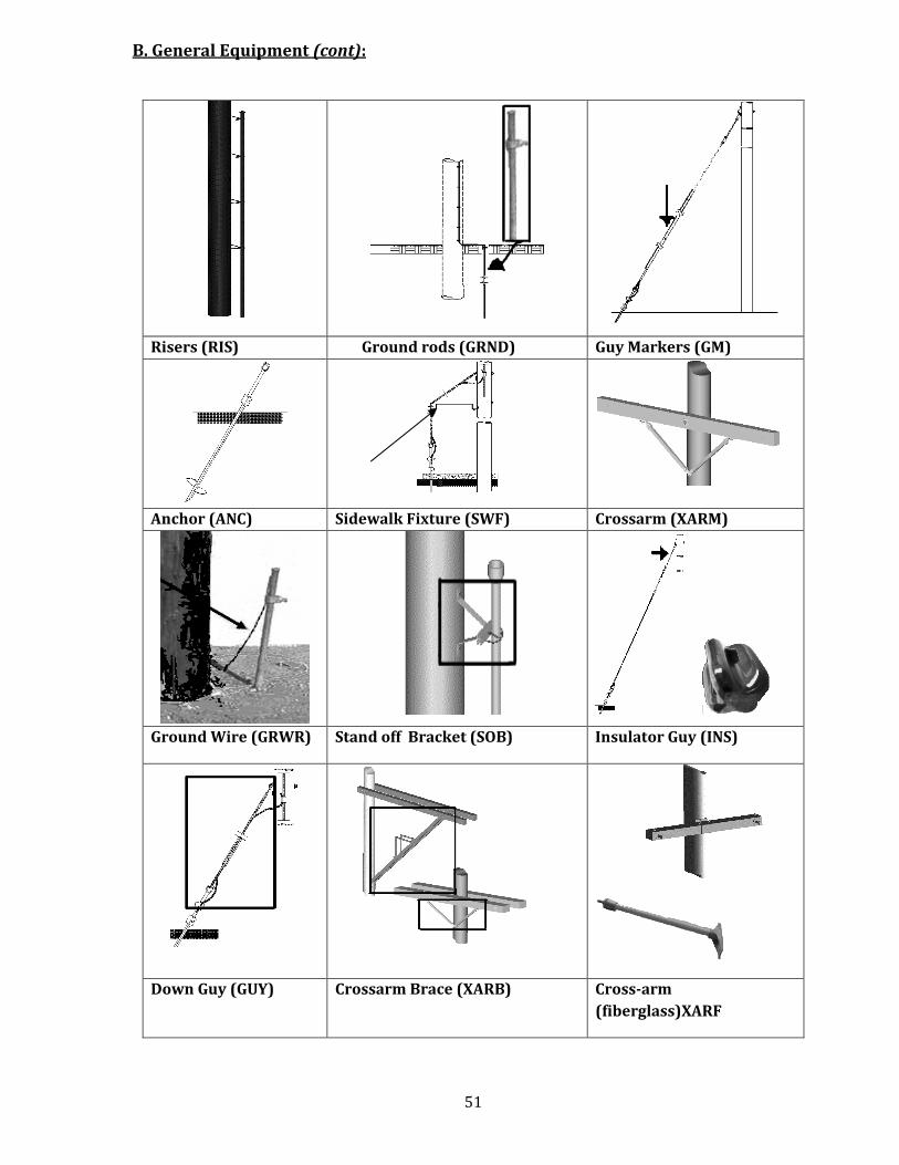
B. General Equipment (cont):
Risers (RIS) Ground rods (GRND) Guy Markers (GM)
Anchor (ANC) Sidewalk Fixture (SWF) Crossarm (XARM)
Ground Wire (GRWR) Stand off Bracket (SOB) Insulator Guy (INS)
Down Guy (GUY) Crossarm Brace (XARB) Cross-arm
(fiberglass)XARF
52
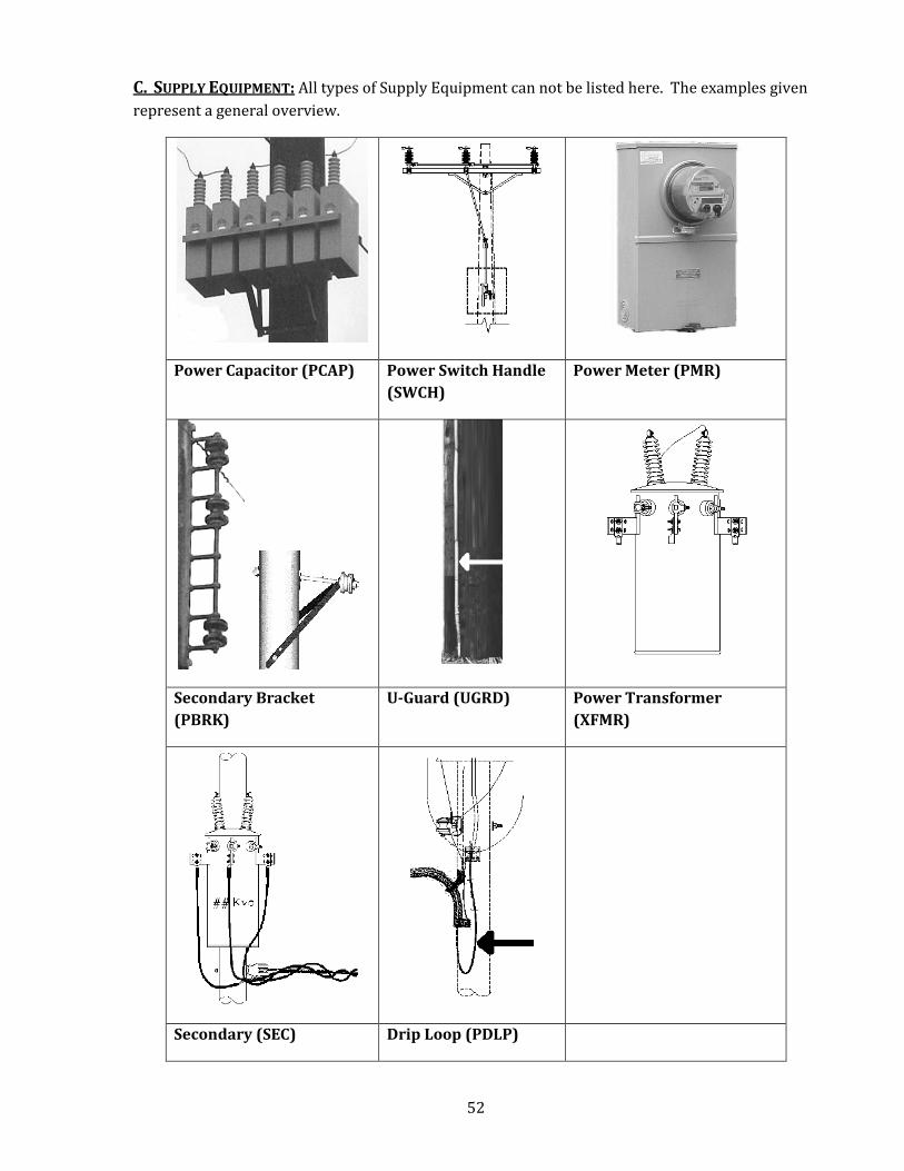
C. SUPPLY EQUIPMENT: All types of Supply Equipment can not be listed here. The examples given
represent a general overview.
Power Capacitor (PCAP) Power Switch Handle
(SWCH)
Power Meter (PMR)
Secondary Bracket
(PBRK)
U-Guard (UGRD) Power Transformer
(XFMR)
Secondary (SEC) Drip Loop (PDLP)
53
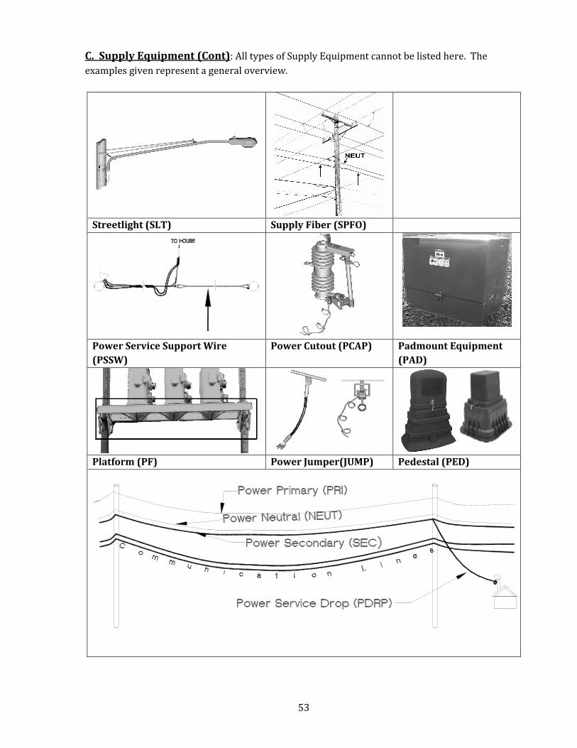
C. Supply Equipment (Cont): All types of Supply Equipment cannot be listed here. The
examples given represent a general overview.
Streetlight (SLT) Supply Fiber (SPFO)
Power Service Support Wire
(PSSW)
Power Cutout (PCAP) Padmount Equipment
(PAD)
Platform (PF) Power Jumper(JUMP) Pedestal (PED)
54
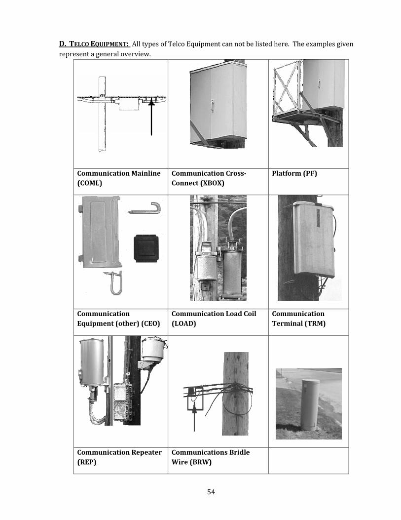
D. TELCO EQUIPMENT: All types of Telco Equipment can not be listed here. The examples given
represent a general overview.
Communication Mainline
(COML)
Communication Cross-
Connect (XBOX)
Platform (PF)
Communication
Equipment (other) (CEO)
Communication Load Coil
(LOAD)
Communication
Terminal (TRM)
Communication Repeater
(REP)
Communications Bridle
Wire (BRW)
55
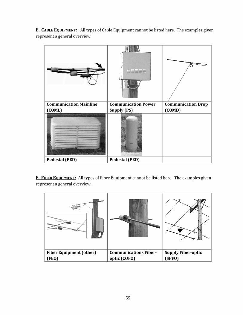
E. CABLE EQUIPMENT: All types of Cable Equipment cannot be listed here. The examples given
represent a general overview.
Communication Mainline
(COML)
Communication Power
Supply (PS)
Communication Drop
(COMD)
Pedestal (PED) Pedestal (PED)
F. FIBER EQUIPMENT: All types of Fiber Equipment cannot be listed here. The examples given
represent a general overview.
Fiber Equipment (other)
(FEO)
Communications Fiber-
optic (COFO)
Supply Fiber-optic
(SPFO)
56
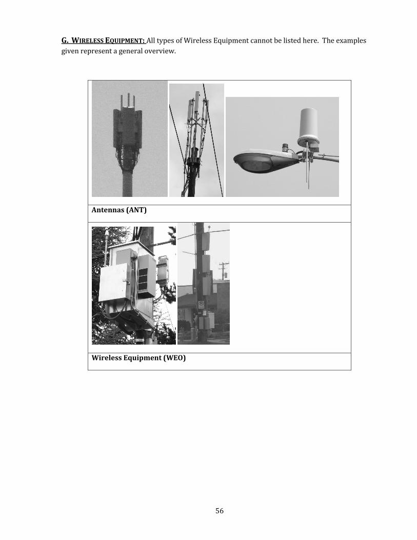
G. WIRELESS EQUIPMENT: All types of Wireless Equipment cannot be listed here. The examples
given represent a general overview.
Antennas (ANT)
Wireless Equipment (WEO)