orbit technology group ltd. - mins tech technology group ltd. ... re-assemble the omt and feed with...
TRANSCRIPT


ORBIT TECHNOLOGY GROUP LTD.
8C Hatzoran St. P.O.B 8657 Tel: +972-9-892-2736 Netanya 42504, Israel Fax: +972-9-892-2820
Document № MAN29-0015 UNCLASSIFIED
SIZE: A
FSCM No.
S5496
File No. MAN29-0015
SCALE: REVISION: -
Page 2
Application Revisions Next Assy. Used On Rev. Description Date Approved
- New Release 22/07/09 IDAN F.
REVISION STATUS
Page Revision 1 - 2 - 3 - 4 - 5 - 6 - 7 - 8 - 9 - 10 - 11 - 12 - 13 - 14 - 15 - 16 -

ORBIT TECHNOLOGY GROUP LTD.
Document № MAN29-0015 UNCLASSIFIED
SIZE: A
FSCM No.
S5496
File No. MAN29-0015
SCALE: REVISION: -
Page 3
GENERAL ARRANGEMENT
1
2
3
4
5 6
7
8 9
1) OMT (TYPx1) 2) Hex socket screw M8x25 + plain washer M8 + spring washer M8 (TYPx6) 3) Hex socket screw M6x18 + plain washer M6 + spring washer M6 (TYPx4) 4) Hex head screw M8x30 + 2 plain washers M8 + spring washer M8 + hex nut M8 (TYPx4) 5) Hex socket screw ¼-20x5/8” + plain washer #1/4 + spring washer #1/4 (TYPx8) 6) Adaptor bracket (TYPx4) 7) Reinforcement arm (TYPx4) 8) Feed (TYPx1)

ORBIT TECHNOLOGY GROUP LTD.
Document № MAN29-0015 UNCLASSIFIED
SIZE: A
FSCM No.
S5496
File No. MAN29-0015
SCALE: REVISION: -
Page 4
9) Pod leg (TYPx4)
Prior to feed replacement verify the following:
A) Antenna inside the radom must be positioned down to it's lowest limit (as shown
in the drawing). B) Main A.C. power is off including SDU power.

ORBIT TECHNOLOGY GROUP LTD.
Document № MAN29-0015 UNCLASSIFIED
SIZE: A
FSCM No.
S5496
File No. MAN29-0015
SCALE: REVISION: -
Page 5
Only one technician is required to replace the feed. Hereby is procedure steps for replacing "c" feed to "ku" feed:
1. Kit “c” disassembling 1.1 Disconnecting cables.
1.1.1 Disconnect "c" Tx cable (black) from the feed
Unplug "n" type connector of the cable from the feed. 1.1.2 Disconnect rx cable (white) from the LNB
Unplug the "f" type connector of the cable from the LNB

ORBIT TECHNOLOGY GROUP LTD.
Document № MAN29-0015 UNCLASSIFIED
SIZE: A
FSCM No.
S5496
File No. MAN29-0015
SCALE: REVISION: -
Page 6
1.1.3 Disconnect "c" Tx cable from the "c" BUC output 1.1.4 Disconnect "l band" cable (yellow) from BUC input. 1.1.5 Disconnect power cable (black) from BUC connector. 1.1.6 Disconnect M&C cable (split) from BUC connector.
1.2 Disassembling of the hardware 1.2.1 OMT
Remove and retain¼ inch UNC screws and attached washers (TYPx4) 1.2.2 Feed’s bracket.
Remove and retainM8 screws with attached nuts and washers (TYPx4)
Remove and retainM6 screws with attached washers. (TYPx8) Remove 4 black brackets to be used in "Ku" feed as well

ORBIT TECHNOLOGY GROUP LTD.
Document № MAN29-0015 UNCLASSIFIED
SIZE: A
FSCM No.
S5496
File No. MAN29-0015
SCALE: REVISION: -
Page 7
1.2.3 Feed
Remove and retainM8 screws with attached washers (TYPx6). Take out the feed. 1.2.4 Feed “c” storage
Re-assemble the OMT and feed with ¼ inch screws and washers (TYPx4) and put it into the storage box.

ORBIT TECHNOLOGY GROUP LTD.
Document № MAN29-0015 UNCLASSIFIED
SIZE: A
FSCM No.
S5496
File No. MAN29-0015
SCALE: REVISION: -
Page 8
2. Assembling “Ku” kit Prior to kit assembling, the following steps are to be done:
A) Turn out 4 fixing short arms of quadropod (see drawing) B) Fix the "C" Tx cable along the quadropod’s leg using gentle tie wraps C) Route the polarizing and "Ku" Tx cables and fix it along the cables channel behind the dish and
along the quadropod legs using tie wraps. Caution: those cables are sensitive, please use gentle tie wraps with minimal force.
“C” cable
“Ku” cables

ORBIT TECHNOLOGY GROUP LTD.
Document № MAN29-0015 UNCLASSIFIED
SIZE: A
FSCM No.
S5496
File No. MAN29-0015
SCALE: REVISION: -
Page 9
2.1 Assembling “Ku” feed Before feed installation do the following steps:
Disconnect the "IF" Rx (red) and "Ku" Tx (silver) cables from rotary joint.
Remove and retain 2 screws M4x16 with attached washers. Remove the rotary joint subassembly from the feed.
2.1.1 “Ku” feed installing and orientation
Insert feed through centering ring from dish side towards out
Feed must be oriented according to the picture in reference to the pod with the cables. Rotary joint must be placed such that secondary channel is out away from black bracket.

ORBIT TECHNOLOGY GROUP LTD.
Document № MAN29-0015 UNCLASSIFIED
SIZE: A
FSCM No.
S5496
File No. MAN29-0015
SCALE: REVISION: -
Page 10
2.1.2 “Ku” feed tightening
Don’t use this hole
Secure the feed to the centering ring byM8x25 screws with attached plain and spring washers (TYPx5)

ORBIT TECHNOLOGY GROUP LTD.
Document № MAN29-0015 UNCLASSIFIED
SIZE: A
FSCM No.
S5496
File No. MAN29-0015
SCALE: REVISION: -
Page 11
2.1.3 Rotary joint assembling
Attach (don’t secure) the rotary joint subassembly by M4 screws with attached plain and spring washers (TYPx2). Gradually secure them while rotating the feed’s axis.
ORBIT TECHNOLOGY GROUP LTD.
Document № MAN29-0015 UNCLASSIFIED
SIZE: A
FSCM No.
S5496
File No. MAN29-0015
SCALE: REVISION: -
Page 12
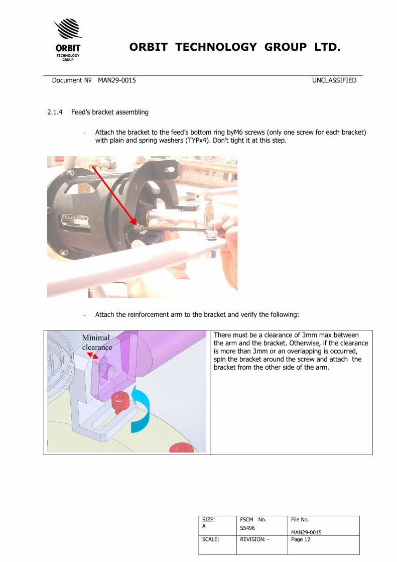
2.1.4 Feed’s bracket assembling
- Attach the bracket to the feed’s bottom ring byM6 screws (only one screw for each bracket) with plain and spring washers (TYPx4). Don’t tight it at this step.
- Attach the reinforcement arm to the bracket and verify the following:
Minimal clearance
There must be a clearance of 3mm max between the arm and the bracket. Otherwise, if the clearance is more than 3mm or an overlapping is occurred, spin the bracket around the screw and attach the bracket from the other side of the arm.
ORBIT TECHNOLOGY GROUP LTD.
Document № MAN29-0015 UNCLASSIFIED
SIZE: A
FSCM No.
S5496
File No. MAN29-0015
SCALE: REVISION: -
Page 13
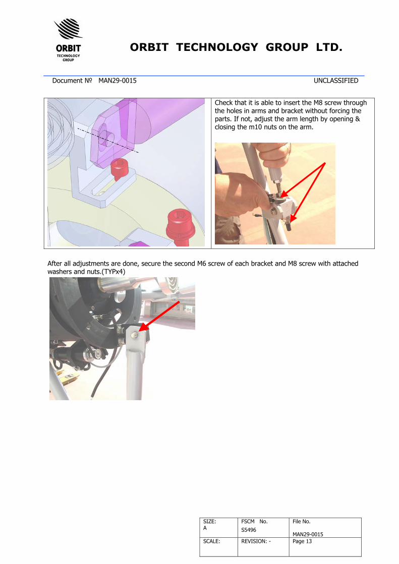
Check that it is able to insert the M8 screw through the holes in arms and bracket without forcing the parts. If not, adjust the arm length by opening & closing the m10 nuts on the arm.
After all adjustments are done, secure the second M6 screw of each bracket and M8 screw with attached washers and nuts.(TYPx4)
ORBIT TECHNOLOGY GROUP LTD.
Document № MAN29-0015 UNCLASSIFIED
SIZE: A
FSCM No.
S5496
File No. MAN29-0015
SCALE: REVISION: -
Page 14
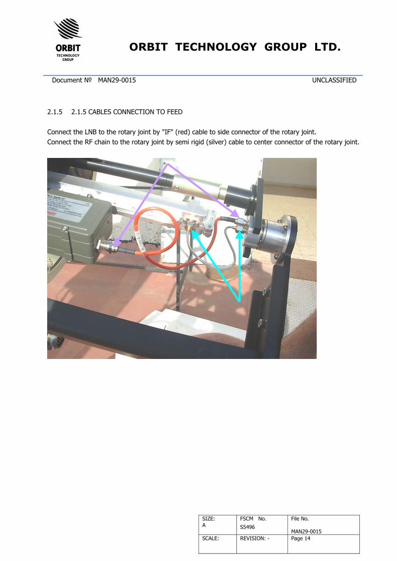
2.1.5 2.1.5 CABLES CONNECTION TO FEED Connect the LNB to the rotary joint by "IF" (red) cable to side connector of the rotary joint. Connect the RF chain to the rotary joint by semi rigid (silver) cable to center connector of the rotary joint.

ORBIT TECHNOLOGY GROUP LTD.
Document № MAN29-0015 UNCLASSIFIED
SIZE: A
FSCM No.
S5496
File No. MAN29-0015
SCALE: REVISION: -
Page 15
Connect "Tx" cable (grey) to the center connector of the rotary joint. Connect "Rx" cable (white) to the short black cable (used as adaptor) and to the side connector of the rotary joint.
2.2 BUC 8w installation 2.2.1 Hardware assembly

ORBIT TECHNOLOGY GROUP LTD.
Document № MAN29-0015 UNCLASSIFIED
SIZE: A
FSCM No.
S5496
File No. MAN29-0015
SCALE: REVISION: -
Page 16
Secure the M8 screw with attached plain and spring washer (TYPx8) 2.2.2 Cable connection
- Connect yellow cable ("n" type) to BUC input connector - Connect grey cable (SMA) to BUC output connector - Connect "y" shape cable to BUC power & M&C connector
3. “Ku” feed disassembling To disassemble “Ku” feed, follow chapter 2 steps backwards.
4. “C” feed assembling To assemble the “c” feed, follow chapter 1 steps backwards.