optimization of conditions of metallothermic reduction...
TRANSCRIPT

OPTIMIZATION OF CONDITIONS OF METALLOTHERMIC REDUCTION OF RARE EARTH PRECONCENTRATES
A THESIS SUBMITTED TO THE GRADUATE SCHOOL OF NATURAL AND APPLIED SCIENCES
OF MIDDLE EAST TECHNICAL UNIVERSITY
BY
SERKAN YILMAZ
IN PARTIAL FULFILLMENT OF THE REQUIREMENTS FOR
THE DEGREE OF MASTER OF SCIENCE IN
METALLURGICAL AND MATERIALS ENGINEERING
JANUARY 2007
Approval of the Graduate School of Natural and Applied Science
Prof. Dr. Canan ÖZGEN Director
I certify that this thesis satisfies all the requirements as a thesis for the degree of Master of Science.
Prof. Dr. Tayfur ÖZTÜRK Head of Department This is to certify that we have read this thesis and that in our opinion it is fully adequate, in scope and quality, as a thesis for the degree of Master of Science. Prof. Dr. Ahmet GEVECİ Prof. Dr. Yavuz TOPKAYA Co-Supervisor Supervisor Examining Committee Members Prof. Dr. Naci SEVİNÇ (METU, METE)
Prof. Dr. Yavuz TOPKAYA (METU, METE)
Prof. Dr. Ahmet GEVECİ (METU, METE)
Prof. Dr. İshak KARAKAYA (METU, METE)
Prof. Dr. Ümit ATALAY (METU, MINE)

iii
I hereby declare that all information in this document has been obtained and presented in accordance with academic rules and ethical conduct. I also declare that, as required by these rules and conduct, I have fully cited and referenced all material and results that are not original to this work. Name, Last name : Serkan YILMAZ
Signature :

iv
ABSTRACT
THE OPTIMIZATION OF CONDITIONS OF METALLOTHERMIC
REDUCTION OF RARE EARTH PRECONCENTRATES
YILMAZ, Serkan
M.S., Metallurgical and Materials Engineering Department
Supervisor: Prof. Dr. Yavuz TOPKAYA
Co-Supervisor: Prof. Dr. Ahmet GEVECİ
January 2007, 65 pages
Rare earth ferrosilicon alloy is an important additive for ferrous metallurgy. It
is mainly used to control the detrimental effects of sulfur in steel and to modify
graphite structures in cast iron. The aim of this study was to optimize the conditions
for the production of rare earth ferrosilicon alloy by metallothermic reduction
process using a preconcentrate prepared from a bastnasite type of ore present in the
Beylikahır-Eskişehir region of Turkey.
In this study, the rare earth preconcentrate was reduced by aluminum together
with ferrosilicon and rare earth ferrosilicon alloys were produced. The optimum
conditions of reduction, which are time, temperature, reducer amounts and the
basicity of the slag phase, were investigated by smelting in an induction furnace. At
the end of the study, a rare earth ferrosilicon alloy containing 39.3 % rare earths,

v
37.5 % silicon, 19.3 % iron and 3.9 % aluminum was produced under the optimum
conditions determined with 57.7 % rare earth metal recovery.
Key words: Rare earth ferrosilicon, bastnasite, metallothermic reduction
vi
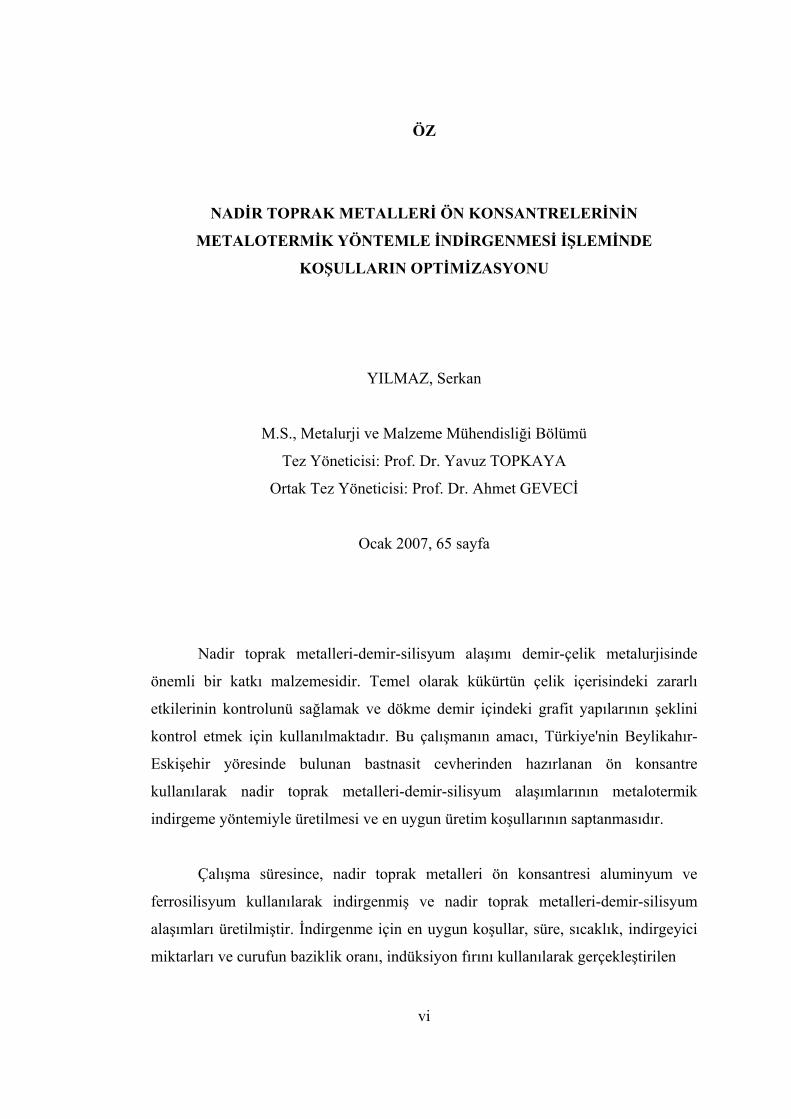
ÖZ
NADİR TOPRAK METALLERİ ÖN KONSANTRELERİNİN
METALOTERMİK YÖNTEMLE İNDİRGENMESİ İŞLEMİNDE
KOŞULLARIN OPTİMİZASYONU
YILMAZ, Serkan
M.S., Metalurji ve Malzeme Mühendisliği Bölümü
Tez Yöneticisi: Prof. Dr. Yavuz TOPKAYA
Ortak Tez Yöneticisi: Prof. Dr. Ahmet GEVECİ
Ocak 2007, 65 sayfa
Nadir toprak metalleri-demir-silisyum alaşımı demir-çelik metalurjisinde
önemli bir katkı malzemesidir. Temel olarak kükürtün çelik içerisindeki zararlı
etkilerinin kontrolunü sağlamak ve dökme demir içindeki grafit yapılarının şeklini
kontrol etmek için kullanılmaktadır. Bu çalışmanın amacı, Türkiye'nin Beylikahır-
Eskişehir yöresinde bulunan bastnasit cevherinden hazırlanan ön konsantre
kullanılarak nadir toprak metalleri-demir-silisyum alaşımlarının metalotermik
indirgeme yöntemiyle üretilmesi ve en uygun üretim koşullarının saptanmasıdır.
Çalışma süresince, nadir toprak metalleri ön konsantresi aluminyum ve
ferrosilisyum kullanılarak indirgenmiş ve nadir toprak metalleri-demir-silisyum
alaşımları üretilmiştir. İndirgenme için en uygun koşullar, süre, sıcaklık, indirgeyici
miktarları ve curufun baziklik oranı, indüksiyon fırını kullanılarak gerçekleştirilen

vii
ergitme işlemleri vasıtasıyla bulunmaya çalışılmıştır. Çalışmanın sonunda bulunan en
uygun koşullarda, ağırlıkça % 39.3 nadir toprak metalleri, % 37.5 silisyum, % 19.3
demir ve % 3.9 aluminyum içeren nadir toprak metalleri-demir-silisyum alaşımı %
57.7 nadir toprak metalleri eldesiyle üretilmiştir.
Anahtar kelimeler: Nadir toprak metalleri-demir-silisyum alaşımı, bastnasit,
metalotermik indirgeme

viii
To My Parents;
Münire and İsmail YILMAZ

ix
ACKNOWLEDGEMENTS
I would like to express my deepest gratitude to my supervisors Prof. Dr.
Yavuz Topkaya and Prof. Dr. Ahmet Geveci for their guidance, patience and
encouragements throughout the research.
I am very thankful to Prof. Dr. Ümit Atalay for providing me the required
facilities in Mining Engineering Department during beneficiation stage of the ore.
I want to thank Salih Türe for his great support, kindness and cheerful
behaviors during the experiments.
Thanks also go to Necmi Avcı and Cengiz Tan for their efforts in analyses of
the samples.
I want to thank, from all my heart, Cem Akıl and Emre Ustaoğlu who are
much more than friends for me, for being with me and turning the most difficult
years of my life into fun.
And finally I must say that it would be so little how much I thank my angels,
Şükran Şen, Sibel Yılmaz and Umur Şen who have never left me alone and made me
feel good and strong with their presence throughout my whole life.

x
TABLE OF CONTENTS
PLAGIARISM ..........................................................................................................iii
ABSTRACT ..............................................................................................................iv
ÖZ ..............................................................................................................................vi
ACKNOWLEDGEMENTS .....................................................................................ix
TABLE OF CONTENTS...........................................................................................x
LIST OF TABLES .................................................................................................xiii
LIST OF FIGURES..................................................................................................xv
CHAPTER
1. INTRODUCTION............................................................................................. 1
2. LITERATURE SURVEY................................................................................. 2
2.1. RARE EARTH ELEMENTS ............................................................................... 2
2.1.1. Place of the Rare Earths in the Periodic Table..................................... 2
2.1.2. Some Properties and Applications of the Rare Earths ......................... 2
2.1.3. Abundance and Resources of the Rare Earths ..................................... 5
2.1.3.1. Bastnasite ....................................................................................... 8
2.1.3.2. Monazite......................................................................................... 8
2.1.3.3. Xenotime........................................................................................ 9
2.2. MISCHMETAL ................................................................................................. 9
2.3. RARE EARTH FERROSILICON .......................................................................... 9
2.3.1. Definition ............................................................................................. 9
2.3.2. Applications ....................................................................................... 10
2.3.2.1. In Steelmaking ............................................................................. 10
2.3.2.2. In Casting ..................................................................................... 11
2.3.3. Production Methods of Rare Earth Ferrosilicon Alloy ...................... 12
2.3.3.1. Carbothermic Reduction .............................................................. 12

xi
2.3.3.2. Metallothermic Reduction............................................................ 13
2.3.3.2.1. Metallothermic Reduction with Ca-Si ................................... 13
2.3.3.2.2. Metallothermic Reduction with Ca-Si and CaC2 ................... 14
2.3.3.2.3. Metallothermic Reduction with a Metal Silicide or Silicon in
an ESR Furnace........................................................................................... 16
2.3.3.2.4. Metallothermic Reduction with Al and Fe-Si ........................ 18
2.3.3.2.4.1. A Brief Explanation ......................................................... 18
2.3.3.2.4.2 Amount of Components to be Charged............................. 18
2.3.3.2.4.3 The Effect of Aluminum and Ferrosilicon........................ 19
2.3.3.2.4.4 The Effect of Flux Additions ............................................ 24
2.3.3.2.4.5. The Effect of Temperature and Holding Time................. 25
2.3.3.2.5. Examples of Production Methods from Different Studies..... 26
3. EXPERIMENTAL METHOD AND PROCEDURE................................... 31
3.1. GENERAL...................................................................................................... 31
3.2. PRODUCTION METHOD ................................................................................. 31
3.3. REDUCTION FURNACE .................................................................................. 32
3.4. CRUCIBLE..................................................................................................... 32
3.5. CHARGE MATERIALS.................................................................................... 34
3.5.1. Rare Earth Metal Source .................................................................... 34
3.5.2. Reducing Agents ................................................................................ 35
3.5.2.1. Choice of Reducing Agents ......................................................... 35
3.5.2.2. Aluminum .................................................................................... 36
3.5.2.3. Ferrosilicon .................................................................................. 36
3.5.3. Lime ................................................................................................... 36
3.6. EXPERIMENTS............................................................................................... 36
3.7. EXPERIMENTAL VARIABLES ......................................................................... 39
4. RESULTS AND DISCUSSION ..................................................................... 40
4.1. GENERAL...................................................................................................... 40
4.2. EFFECTS OF THE EXPERIMENTAL VARIABLES............................................... 40
4.2.1. Effect of the Basicity of the Slag Phase ............................................. 40

xii
4.2.2. Effect of Temperature ........................................................................ 43
4.2.3. Effect of Aluminum Amount in the Charge....................................... 45
4.2.4. Effect of Ferrosilicon Amount in the Charge..................................... 49
4.2.5. Effect of Duration .............................................................................. 50
4.3. EXPERIMENT PERFORMED UNDER THE OPTIMUM CONDITIONS DETERMINED
................................................................................................................................ 52
4.4. EXPERIMENT PERFORMED USING THE PRECONCENTRATE WITH HIGHER REO
GRADE .................................................................................................................... 53
5. CONCLUSIONS ............................................................................................. 55
REFERENCES......................................................................................................... 57
APPENDICES
A: CALCULATION OF THE COMPOSITION OF PRECONCENTRATE
CONTAINING 23.13% REO FROM SEM ANALYSIS .......................................... 60
B: CALCULATION OF THE COMPOSITION OF PRECONCENTRATE
CONTAINING 31.11% REO FROM SEM ANALYSIS .......................................... 63
xiii
LIST OF TABLES
TABLES
Table 2.1. Some of the important properties of the rare earth elements ..................... 4
Table 2.2. Some of the important rare earth minerals ................................................. 7
Table 2.3. Typical analysis of some commercial rare earth ferrosilicon alloys (wt.%)
.................................................................................................................................... 10
Table 2.4. Plane strain fracture toughness of pearlitic gray cast iron ....................... 11
Table 2.5. Actual values of points in Figure 2.4. ...................................................... 16
Table 2.6. Phase compositions with respect to silicon content ................................. 23
Table 2.7. Effects of excessive amounts of aluminum and ferrosilicon addition in the
charge ......................................................................................................................... 23
Table 2.8. Results of a test from the study of Mitchell et al. ..................................... 26
Table 2.9. Results of a test from the study of Morrice et al. ...................................... 27
Table 2.10. Results of a test from the study of Marchant et al. ................................ 28
Table 2.11. Results of the tests from the study of Mehra et al. ................................. 29
Table 2.12. Results of the test from the study of Turgay .......................................... 30
Table 3.1. Composition of the preconcentrate ........................................................... 34
Table 3.2. Experimental variables.............................................................................. 39
Table 4.1. The effect of the basicity of the slag phase on alloy composition and rare
earth recovery............................................................................................................. 41

xiv
Table 4.2. The effect of temperature on alloy composition and rare earth recovery . 44
Table 4.3. The effect of aluminum addition on alloy composition and rare earth
recovery...................................................................................................................... 46
Table 4.4. The effect of ferrosilicon addition on alloy composition and rare earth
recovery...................................................................................................................... 49
Table 4.5. Effect of duration on alloy composition and rare earth recovery ............. 51
Table 4.6. Results of the experiment performed under the optimum conditions ....... 53
Table 4.7. Composition of the preconcentrate containing 31.11 % REO ................. 54
Table 4.8. Results of the experiment made with the preconcentrate containing
31.11% REO .............................................................................................................. 54

xv
LIST OF FIGURES
FIGURES
Figure 2.1. Periodic table showing rare earth elements and scandium, yttrium .......... 3
Figure 2.2. Abundance of rare earths and certain common elements in the earth’s
crust ............................................................................................................................. 6
Figure 2.3. Individual abundances of rare earths ........................................................ 6
Figure 2.4. Three coordinate diagram invented by Kallenbach and Bungardt ......... 15
Figure 2.5. Formation energies of rare earth oxides and some other oxides vs.
Temperature .............................................................................................................. 21
Figure 2.6. Binary phase diagram of (50%La-50%Ce)-Si ........................................ 22
Figure 3.1. Technical drawing of the graphite crucible and its lid ............................ 33
Figure 3.2. XRD pattern of bastnasite preconcentrate ............................................... 35
Figure 3.3. Flowchart of the experiments .................................................................. 38
Figure 4.1. RE-metal recovery vs. Basicity of the slag phase.................................... 41
Figure 4.2. XRD pattern of the slag phase with the basicity ratio of two .................. 42
Figure 4.3. SEM micrograph of an experiment realized with a basicity ratio of 1.3. 43
Figure 4.4. RE-metal recovery vs. Reaction temperature .......................................... 44
Figure 4.5. RE-Metal recovery vs. % Aluminum addition of the stoichiometric
amount........................................................................................................................ 47

xvi
Figure 4.6. RE-Metal recovery vs. % FeSi addition of the stoichiometric amount ... 50
Figure 4.7. RE-Metal recovery vs. Duration.............................................................. 51

1
CHAPTER 1
INTRODUCTION
The rare earth elements consist of 17 chemically similar elements which are
scandium, yttrium and the lanthanides. Although about 250 rare earth containing
minerals are known, three of them which are bastnasite, monazite and xenotime are
the main sources of the rare earths. The rare earth ore beds in Turkey which contain
bastnasite type rare earth mineral are found in the Beylikahır-Eskişehir region.
The rare earths as metals, alloys or compounds have found use in many
different application areas. Especially rare earth ferrosilicon alloy is utilized in
steelmaking industry for deoxidation and desulfurization of steel and modification of
sulfide inclusions in steel. Also it is used as an additive for cast iron to increase the
tensile strength of grey cast iron. In both cases, the addition of rare earth ferrosilicon
alloy increases the properties of the product.
Rare earth ferrosilicon alloy, the typical analysis of which consists of about
30% of each of its major constituents, is produced by two different reduction
methods; carbothermic reduction and metallothermic reduction. Metallothermic
reduction method gives a higher rare earth recovery and a better grade than
carbothermic reduction method.
Optimization of the conditions of rare earth ferrosilicon alloy production by
metallothermic reduction method using the rare earth preconcentrate produced from
the ore taken from Beylikahır-Eskişehir region of Turkey was the main aim of this
study.

2
CHAPTER 2
LITERATURE SURVEY
2.1. Rare Earth Elements
2.1.1. Place of the Rare Earths in the Periodic Table
The term “rare earths” (symbolized as RE or REE) denotes the group of 17
chemically similar metallic elements, including scandium, yttrium, and the
lanthanides. The lanthanide (Ln) group comprises 14 elements which have atomic
numbers ranging from 58 (cerium) to 71 (lutetium) which are located in 6th row of
the periodic table following lanthanum, and whose properties resemble those of
lanthanum. For this reason lanthanum is also included in the group and responsible
for the name “lanthanides” (e.g., resembling lanthanum). Moreover, scandium and
yttrium, which belong to group III, are almost always present together with the
lanthanides in minerals and have similar properties with lanthanides. Except
promethium, all of the rare earths occur in nature [1,5]. The place of the rare earth
elements in the periodic table is shown in Figure 2.1.
2.1.2. Some Properties and Applications of the Rare Earths
All the rare earths are typical transition metals, with high lustre and electrical
conductivity. They are silver, silver-white or grey in colour and in their metallic form
they are soft and ductile. Chemically, REE are strong reducing agents and their
compounds are generally ionic. Most of the rare earth elements are trivalent, with
europium also having a valance of +2 and cerium also having a valance of +4. In air,
the rare earths tend to tarnish rapidly forming rare earth oxides (REO). Because of

3
their chemical similarity, it is exceedingly difficult to separate them from each other
and they behave as a single chemical entity. All the rare earths are paramagnetic,
except Gd, Dy and Ho, which have ferromagnetic properties [1,2,3].
H HeLi Be B C N O F NeNa Mg Al Si P S Cl Ar K Ca Sc Ti V Cr Mn Fe Co Ni Cu Zn Ga Ge As Se Br Kr Rb Sr Y Zr Nb Mo Tc Ru Rh Pd Ag Cd In Sn Sb Te I XeCs Ba La Hf Ta W Re Os Ir Pt Au Hg Tl Pb Bi Po At RnFr Ra Ac Ce Pr Nd Pm Sm Eu Gd Tb Dy Ho Er Tm Yb Lu Th Pa U Np Pu Am Cm Bk Cf Es Fm Md No Lw
Figure 2.1. Periodic table showing rare earth elements (light shaded) and scandium,
yttrium (highlighted)
The rare earths, used as metals, alloys and chemical compounds, have an ever
growing variety of applications in the modern technology; Ferrous and nonferrous
metallurgy, production of glass and ceramics, the chemical industry, production of
permanent magnets, nuclear applications and many more. They still have other
potential uses, the number of which increases as the properties of lanthanides, their
alloys and compounds become known [1,5]. Some of the important properties of the
rare earths are given in Table 2.1.
The largest single application of rare earths is in the manufacture of rare earth
containing zeolite cracking catalysts required in the petroleum refining process since
about 35 % of REE are used as catalysts. REE’s are also included in catalytic
converters which are used to control vehicle exhaust emissions in automobiles [2,5].
Rare earths are used extensively in glass and ceramics industry. They find use
as decolourising agents, glass-polishing compounds, UV absorbers and antibrowning
agents, glass and ceramic colourising agents, activators in laser glasses. They are also

4
used as additives to structural ceramics such as stabilized zirconia and in optical
lenses and glasses [1,2].
Table 2.1. Some of the important properties of the rare earth elements [2]
Element
Symbol
Atomic
no.
Atomic
wt.
Density(g/cm3)
Valence
Melting
point (oC)
Boiling
point (oC)
Lanthanum La 57 138.9 6.15 3 918 3464
Cerium Ce 58 140.12 6.77 3,4 789 3443
Praseodymium Pr 59 140.98 6.44 3 931 3520
Neodymium Nd 60 144.24 7.01 3 1021 3074
Promethium Pm 61 145 7.26 3 1042 3000
Samarium Sm 62 150.4 7.52 3 1074 1794
Europium Eu 63 151.96 5.2 3,2 822 1527
Gadolinium Gd 64 157.25 7.9 3 1313 3273
Terbium Tb 65 158.93 8.23 3 1356 3230
Dysprosium Dy 66 162.5 8.55 3 1412 2567
Holmium Ho 67 164.93 8.8 3 1474 2700
Erbium Er 68 167.26 9.1 3 1529 2868
Thulium Tm 69 168.93 9.34 3 1545 1950
Ytterbium Yb 70 173.04 7 3 819 1196
Lutetium Lu 71 174.97 9.84 3 1663 3402
Scandium Sc 21 44.96 3 3 1541 2836
Yttrium Y 39 88.91 4.47 3 1522 3338

5
Rare earth elements, notably cerium and mischmetal (Ce+La+Nd), have also
been used as minor alloying additives for controlling shape of inclusions in cast iron
and steel. The addition of rare earth metals to various aluminum, titanium and
magnesium alloys increases their properties as in the ferrous metallurgy such as
high-temperature and creep strength [1,5,7].
Apart from the applications mentioned, rare earths are also utilized in
permanent magnets, lighter flints, nuclear technology, electronics, rechargeable
batteries and many others number of which is growing day by day.
2.1.3. Abundance and Resources of the Rare Earths
“Rare” earth elements is a historical misnomer; persistence of the term
reflects unfamiliarity rather than true rarity. In terms of inherent abundance in the
earth’s crust, the rare earths are not rare because the total rare earths abundance (220
ppm) is more than that of even carbon (200 ppm), and several rare earth elements are
more abundant than many better known metals. The most common rare earths are La,
Ce and Nd. Rare earths with odd atomic numbers are less abundant than their
immediate neighbors with even atomic numbers. These facts are presented in Figures
2.2. and 2.3 [1,5,8].
Rare earth elements are classified into two groups: The light or cerium
subgroup comprising the first seven elements whose atomic numbers are from 57 to
63 (La, Ce, Pr, Nd, Pm, Sm, Eu) and the heavy or yttrium subgroup comprising the
elements with atomic numbers from 64 to 71 ( Gd, Tb, Dy, Ho, Er, Tm, Yb, Lu, Y).
Despite its low atomic weight yttrium is categorized with the heavy REE because its
properties are closer to those of the heavier REE than to the lighter group [2,4].

6
Figure 2.2. Abundance of rare earths and certain common elements in the
earth’s crust [5]
Figure 2.3. Individual abundances of rare earths [1]

7
Although more than 250 rare earth containing minerals are known, about 95
% of the rare earths occur in only three minerals; bastnasite, monazite and xenotime.
Some properties of the minerals are shown in Table 2.2.
Table 2.2. Some of the important rare earth minerals [5]
Mineral Formula Rare earth content (%)
Other constituents (%)
Bastnasite (Ce,La,Pr)(CO3)F Ce2O3 36.9-40.5; (La, Pr,...)2O3 36.3-36.6
CO2 19.8-20.2 F 6.2-8.5
Euxanite (Y,Ce,Ca,U,Th)(Ti,Nb,Ta)2O6 (Y,Er)2O3 18.2-27.7 (Ce,La,...)2O3 16-30
TiO2 16-30; Nb2O5 4.3-47.4; Ta2O5 1.3-23;
ThO2 1-5; UO2 0.4-12
Fergusonite (Y,Sr,Ce,U)(Nb,Ta,Ti)O4 Y2O3 31-42;
(Ce,La,...)2O3 0.9-6; Er2O3 0-14
(Nb,Ta)2O5 46-57.5; ThO2 1-3.4; UO2 1.2-6; TiO2 0-6;
also ZrO2, SnO2, WO3
Gadolinite (Y,Ce)2FeBe2Si2O10 Y2O3 30.7-46.5 ;
(Ce,La,...)2O3 16-30
FeO 10-13.7; SiO2 23-24.5; ThO2 0.3-0.4; BeO 9-10.2; also Ca, Mg
Loparite (Na,Ca,Ce,Sr)2(Ti,Ta,Nb)2O6 (Ce,La,...)2O3 32-34
TiO2 39.2-40; (Nb,Ta)2 8-11; CaO 4.2-5.2; Na2O 7.8-9;
also Sr, K, Si, Th
Monazite (Ce,La,...)PO4 (Ce,La,...)2O3 32-34
P2O5 22-31.5; ThO2 4-12; U 0.1-0.3;
ZrO2 0 to 7; SiO2 0 to 6
Orthite (Ca,Ce)2(Al,Fe)3Si3O12 [O,OH]Ce2O3 0-6; La2O3 0-7; Y2O3; 0-8
BeO 3.8; also ThO2
Parisite Ca(Ce,La,...)2(CO3)F2 Ce2O3 26-31;
(La,Nd,...)2O3 27.3-30.4;Y 8
CaO 10.4-11.4; CO2 23-24.5;
F 6-7
Xenotime YPO4 Y2O3 52-62
ThO2, UO2 up to 5;
ZrO2 3; SnO,
SiO2 9
Yttrocerite (Ca,Y,Ce,Er)F2-3H2O Ce 8.5-11.5; Y 14.3-37.7
Ca 19.7-32.7; F 37.7-41.6

8
2.1.3.1. Bastnasite
The mineral bastnasite is a fluorocarbonate of the cerium group rare earth
metals with an ideal formula of LnFCO3 or (Ce, La,…)FCO3 and hardly contains any
thorium. The specific gravity of bastnasite is 4.9-5.2, its hardness is 4-4.5 and it is
yellow to brown in colour. Bastnasite occurs as veins or dissemination in a complex
of carbonate-silicate rocks, in quartz veins, fluorite-bearing veins and quartzite [5,6].
Bastnasite ore is generally treated by conventional mineral processing technology,
that is, communition followed by froth flotation [9].
Bastnasite has been identified in various locations on several continents. The
two most important deposits of rare earths are found in Bayan Obo in China (800
million metric tons; 6 % REO) and at Mountain Pass, California in the US (3.3
million metric tons; 7.7 % REO) [5,10]. Rare earth ore beds in Turkey are situated in
the Beylikahır-Eskişehir region, and are consisted of bastnasite type rare earth
mineral.
2.1.3.2. Monazite
The mineral monazite is a phosphate, mainly of the cerium group rare earths
and thorium. It is a red, brown or yellow, translucent mineral which is generally
denoted by (Ce,La,Th,Y)PO4. Its specific gravity is 4.9-5.3 and the hardness 5-5.5.
The mineral is very inert and resistant to water attack. Monazite is found in many
geological environment. It occurs as an accessory mineral in acidic igneous rocks, in
metamorphic rocks, and in certain vein deposits. Due to its chemical stability it also
develops into detrital mineral in placer deposits and beach sands [5].
Some and the most important sources of monazite are beach placers. Beach
sand deposits also contain other heavy minerals such as ilmenite, rutile and zircon.
The primary monazite deposits have been useful as rare earth resources in a few
instances and some of them are in South Africa, US, China, Australia and India [5].

9
2.1.3.3. Xenotime
Xenotime is a yttrium phosphate mineral whose chemical formula is YPO4. It
contains about 67 % REO, mostly of the heavier elements. Xenotime is typically
translucent to opaque (rarely transparent) in shades of brown to brownish yellow, but
also reddish to greenish brown and gray. Its specific gravity is 4.4-5.1.
The most important deposits of xenotime are in Malaysia, Australia,
Indonesia, Thailand, China and Brazil [5].
2.2. Mischmetal
Mischmetal is a mixture of the rare earth metals and varies in composition,
depending on the material that is reduced. Its typical composition includes
approximately 45-50 % Ce, 22-25 % La, 14-17 % Nd, 5-8 % Pr, 2-3 % Sm, 0.2-0.5
% Fe and small amounts of other rare earth metals and tracers which are mainly Al,
C, O, N. Large-scale commercial production of mischmetal is presently limited to the
electrolysis of fused anhydrous chlorides [11].
The most common use of mischmetal is in the "flint" ignition device of many
lighters and torches. Also it is utilized in cast iron and steel technology to improve
the quality of product [11].
2.3. Rare Earth Ferrosilicon
2.3.1. Definition
Rare earth ferrosilicon is an alloy which mainly consists of, as the name
regards, mixed rare earth metals, iron and silicon. The alloy is the most extensively
used form of rare earths in cast iron and steel making technology. Typical analysis of
some of the commercial rare earth ferrosilicon alloys are given in Table 2.3.
Production of rare earth ferrosilicon is the main concern of this thesis study.
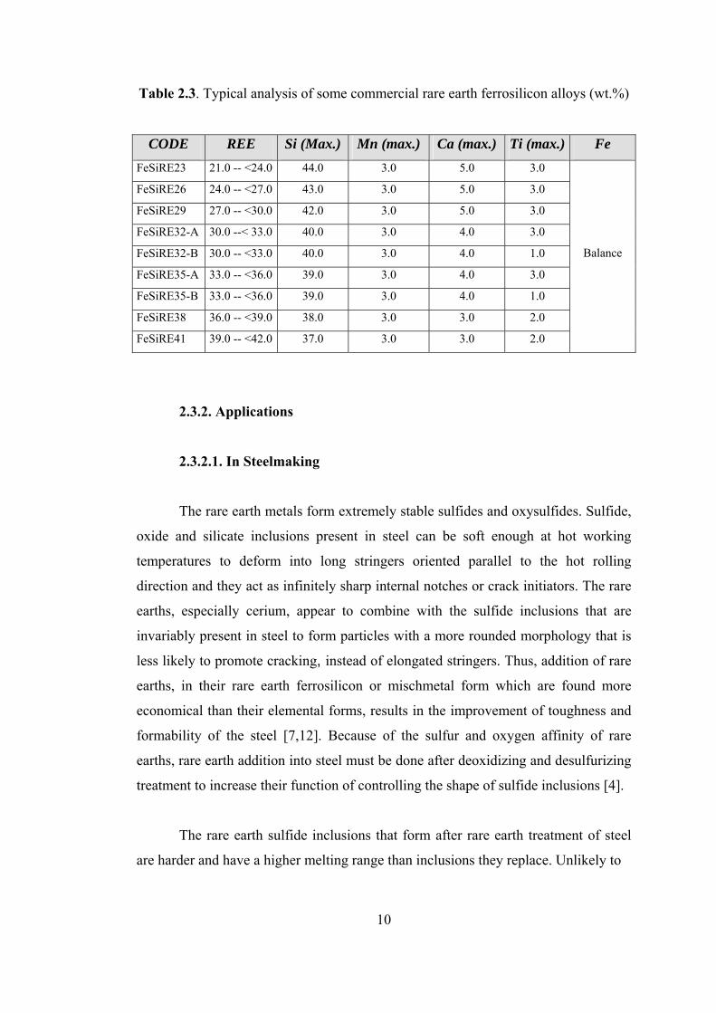
10
Table 2.3. Typical analysis of some commercial rare earth ferrosilicon alloys (wt.%)
CODE REE Si (Max.) Mn (max.) Ca (max.) Ti (max.) Fe FeSiRE23 21.0 -- <24.0 44.0 3.0 5.0 3.0
FeSiRE26 24.0 -- <27.0 43.0 3.0 5.0 3.0
FeSiRE29 27.0 -- <30.0 42.0 3.0 5.0 3.0
FeSiRE32-A 30.0 --< 33.0 40.0 3.0 4.0 3.0
FeSiRE32-B 30.0 -- <33.0 40.0 3.0 4.0 1.0
FeSiRE35-A 33.0 -- <36.0 39.0 3.0 4.0 3.0
FeSiRE35-B 33.0 -- <36.0 39.0 3.0 4.0 1.0
FeSiRE38 36.0 -- <39.0 38.0 3.0 3.0 2.0
FeSiRE41 39.0 -- <42.0 37.0 3.0 3.0 2.0
Balance
2.3.2. Applications
2.3.2.1. In Steelmaking
The rare earth metals form extremely stable sulfides and oxysulfides. Sulfide,
oxide and silicate inclusions present in steel can be soft enough at hot working
temperatures to deform into long stringers oriented parallel to the hot rolling
direction and they act as infinitely sharp internal notches or crack initiators. The rare
earths, especially cerium, appear to combine with the sulfide inclusions that are
invariably present in steel to form particles with a more rounded morphology that is
less likely to promote cracking, instead of elongated stringers. Thus, addition of rare
earths, in their rare earth ferrosilicon or mischmetal form which are found more
economical than their elemental forms, results in the improvement of toughness and
formability of the steel [7,12]. Because of the sulfur and oxygen affinity of rare
earths, rare earth addition into steel must be done after deoxidizing and desulfurizing
treatment to increase their function of controlling the shape of sulfide inclusions [4].
The rare earth sulfide inclusions that form after rare earth treatment of steel
are harder and have a higher melting range than inclusions they replace. Unlikely to

11
other oxide, sulfide and oxysulfide inclusions, the rare earth sulfide inclusions do not
deform during hot working and remain globular. This fact is especially important in
carbon and HSLA steels for automotive applications [13,14].
2.3.2.2. In Casting
A typical microstructure of gray cast iron consists of a large fraction of
graphite flakes that behave as notches or cracks, reducing both ductility and
toughness. The mechanical properties depend on the volume fraction and shape of
the dispersed graphite, and the properties of the matrix. On the other hand, nodular
iron has properties similar to mild steel and is essentially a ductile cast iron. Nodular
iron results when the graphite flakes in cast iron are converted to nodules. The
addition of mischmetal or rare earth ferrosilicon into cast iron melt causes the
graphite to separate into a nodular form. As the nodules do not form points of stress
concentration, the mechanical properties of the product are markedly improved [15,
16]. Table 2.4. shows plane strain fracture toughness of pearlitic gray cast iron with
respect to graphite structure.
Table 2.4. Plane strain fracture toughness of pearlitic gray cast iron [16]
KIC (MPa m1/2) Graphite Structure Experimental Theoretical Lamellar 28.1 23.0 Nodular 57.3 58.0
Steel Matrix ~70.0 ~70.0 In the manufacture of nodular iron, rare earths are added as mischmetal or
rare earth ferrosilicon and not as pure rare earth metals, mainly due to cost
consideration. The rare earth elements cleanse the metal of elements that prohibit
spherical graphite growth, and the compounds they then form provide heterogeneous
substrates for graphite nucleation. Its good physical and foundry properties have
made nodular iron, so that rare earth ferrosilicon, attractive engineering material,
particularly in the automotive industry [5].

12
2.3.3. Production Methods of Rare Earth Ferrosilicon Alloy
2.3.3.1. Carbothermic Reduction
Carbothermic reduction process makes use of carbon to extract metal values
from rare earth metal sources. Reduction process is carried out in a submerged arc
furnace using carbon electrodes, since temperatures in excess of 1930 ˚C are
required, according to the general reaction;
Metal Oxide + Carbon = Metal + CO (1)
Rare earth metal source required to produce a rare earth ferrosilicon alloy by
carbothermic reduction may be rare earth metal oxides, carbonates, phosphates,
silicates, fluorocarbonates. Compounds in the form of ore or ore concentrates of the
rare earth metals can be used as well as relatively pure materials. However,
commercially available rare earth metal compounds are generally in the form of fine
powders which are difficult to add to a reduction furnace without loss of the metal
values due to dusting. Therefore, it is desirable to agglomerate the fine rare earth
metal compounds prior to the carbothermic reduction [17].
Silica, iron and carbon which are required for the carbothermic reduction
process may be supplied in any conventional form. For example, sand or quartz may
be used as a source of silica, and carbon may be supplied as coal, coke or
combinations of several carbonaceous materials. Iron, for economic reasons, is
supplied in the form of steel scrap, although any sources of iron could be used in the
process [17].
Carbon required for the reduction of rare earth metal oxides, other metal
oxides and silica must be in excess of the stoichiometric amount. The amount of
carbon required for the carbothermic reduction process varies from 10 % to 50 % in
excess of the stoichiometric amount depending on the specific furnace conditions
employed in the process. Using excessive amount of carbon serves to secure

13
complete reduction of the silica used in the reduction process. This has a beneficial
effect that the formation of rare earth metal carbides is suppressed since silicon
favors the production of rare earth metal silicides rather than rare earth metal
carbides [17].
2.3.3.2. Metallothermic Reduction
2.3.3.2.1. Metallothermic Reduction with Ca-Si
As Sump [18] stated in 1966, a rare earth metal silicon alloy can be produced
by reducing the rare earth source with Ca-Si that contains preferably 30 % calcium.
In his method, a mixture of rare earth source, calcium silicide as the reducing agent
and silica as a fluxing agent is melted in a graphite crucible in an electric arc furnace.
The rare earth compounds which can be reduced by the process of this
invention may be rare earth oxides, carbonates, phosphates, silicates and
fluorocarbonates. Compounds in the form of ores or ore concentrates of the rare
earths can be utilized as well as relatively pure materials such as cerium oxide or
mixed cerium lanthanum oxide [18].
It is also very important that silica be present in the reaction mixture since it
serves a two-fold purpose; first, silica avoids the catastrophic attack upon the
graphite crucible by the highly reactive rare earth metals, secondly, separation and
the removal of the alloy from other products are simplified by using silica. The
amount of silica varies from 3 % to 15 %, but a preferred amount is about 10 %
based on the combined weight of rare earth compound and reducing metal [18].
Because of the high melting temperatures of the rare earth compounds, the
reduction must be carried out in an electric arc furnace with graphite electrodes.
Especially at high temperatures, it is very possible for rare earths to react with
graphite crucible, therefore, conventional electric furnaces which provide heat
through the walls of the crucible can not be utilized for this process. Further, Sump

14
utilized “cold-wall” graphite crucibles in his study to prevent the reaction between
the crucible and the mixture [18].
In a test carried out by Sump et al. [18], a mixture of 4.53 kg rare earth oxide,
6.8 kg Ca-Si ( 30 % calcium) and 1.13 kg SiO2 was charged into an electric arc
furnace using graphite electrodes with a “cold-wall” graphite crucible. The furnace
was operated as a direct current arc at 1400 amperes and 35 volts for 50 minutes. The
alloy was cast into molds after the reduction. Ingot alloy recovery was 7.25 kg per
run. The entire melting and casting operations were conducted in the absence of a
protective atmosphere. The total rare earth content of the product alloy was 42.5 %
by weight. It also contained 51 % Si, 4.6 % Ca and 1.9 % Fe.
2.3.3.2.2. Metallothermic Reduction with Ca-Si and CaC2
As Bungart and Kallenbach [19] stated in their studies, an improved process
for producing master alloys of the rare earth metals and silicon which is devoid of
technical difficulties and which yields a product containing 40 % or more of rare
earth metals could be accomplished by this type of reduction. The technique depends
on the conditions that the silicon starting or base alloy should contain between about
5 % and 40 % by weight calcium, a portion of the calcium-silicon base alloy should
be replaced by a predetermined quantity of calcium carbide and the mixture of
calcium-silicon alloy and calcium carbide should be reacted with a predetermined
quantity of rare earth metal oxides or salts at an elevated temperature.
According to this study the process needs a reaction mixture containing
preferably between 35 % and 50 % by weight rare earth metal oxides or equivalent
amount of rare earth metal salts, between 25 % and 62.5 % by weight of a calcium-
silicon alloy which contains between about 5 % and 40 % by weight calcium and
between about 2.5 % and 25 % by weight calcium carbide. This mixture is heated to
a temperature within the range of 1200 ˚C to 1800 ˚C to have an effective reduction
and to form the desired master alloy product. Consequently the master alloy obtained
is separated from the secondary products of the reaction. Also the reaction is carried

15
out in the presence of a flux which absorbs these sluggy reaction products and
contains one or more chlorides or fluorides of the alkaline earth metals and
preferentially added to the reaction mixture in an amount such that the overall
mixture contained from about 5 % to 20 % by weight of said flux [19].
A three coordinate diagram which was found by Walter Bungardt and Rudolf
Kallenbach is given in Figure 2.4. It is shown in this diagram that the relative
proportions of the rare earth oxides, calcium silicon alloy and calcium carbide in the
reaction mixture should be somewhere inside the area which is defined by the points
A, B, C and D. The area defined by the points A’, B’, C’ and D’ which is also plotted
on the mentioned diagram indicates a particularly more advantageous area for this
constituents to fall. The actual values of these points are given in Table 2.5 [19].
Figure 2.4. Three coordinate diagram invented by Kallenbach and Bungardt [19]

16
Table 2.5. Actual values of points in Figure 2.4. [19]
RE-metal oxides (wt.%)
Ca-Si Alloy (wt.%)
CaC2 (wt.%)
A 35 62.5 2.5 B 50 47.5 2.5 C 35 40 25 D 50 25 25 A’ 40 55 5 B’ 50 45 5 C’ 40 40 20 D’ 50 30 20
In one of the examples given by Bungart et al. [19] a reaction mixture which
consisted of 24 grams of commercial mixed rare earth metal oxides, 27 grams of a
commercial calcium silicon alloy (64.3 % Si, 27.3 % Ca, 3.8 % Fe), 9 grams of
commercial calcium carbide (80 % CaC2) and 15 grams of commercial calcium
fluoride as a flux was prepared. Reaction was carried out in a graphite crucible at
about 1550 °C and then a 30 grams weighed metal product which contained 54.6 %
mischmetal, 30.9 % silicon, 5.7 % calcium and other impurities was obtained. The
recovery was approximately 83 %.
2.3.3.2.3. Metallothermic Reduction with a Metal Silicide or Silicon in an
ESR Furnace
This modified technique was found by Herchenroeder [20] in 1976 and it
relates to methods of making reactive metal silicide (including rare earth silicide) and
particularly to methods of making master alloys of lanthanum and silicon, and of
other reactive metals and silicon in an ESR (electro-slag refining) furnace.
In prior methods a mixture of rare earth oxides and metal silicides was heated
to promote a reaction to form metal oxide slag and a rare earth-silicon alloy. Calcium
carbide and iron were added to improve the reaction. However, these methods were
not satisfactory for producing lanthanum-silicon alloy with any degree of efficiency

17
and economy. If reactants are simply blended and heated to a temperature to cause a
reaction between the reactive metal oxides and silicon but not to cause a fluid slag
the resulting alloy is intermingled with the slag product and need an ore dressing
operation to recover the alloy. If mixture is heated to a slag forming temperature
there are reactions with the normal reaction vessels such as carbon or ceramics which
is undesirable. Herchenroeder suggested a method that a rare earth silicon alloy
which was clearly separated from the slag components could be provided without
need for further cleaning operations and which could be used directly as an additive
in metal making operation [20].
A nonreactable water cooled crucible which was usually constructed of
copper was used in mentioned technique to avoid contamination of the product alloy.
Because of the intensity of ESR furnace the slags are relatively controllable and the
process is efficient.
Preferentially, Herchenroeder [20] fed a mixture of rare earth metal oxide and
metal silicide or silicon into a slag pool formed between a non-consumable electrode
and the base of a water cooled crucible to form a pool of rare earth metal silicon
alloy covered with slag, raising the electrode as the molten bath rises in the
container, to allow the alloy to solidify beneath the slag and then separate the slag
and rare earth metal silicon alloy.
Flux materials such as fluorspar could be added to maintain the slag in fluid
condition throughout the process. Rare earth metal concentrations of the product
alloy obtained from this operation were generally above 50% [20].
In an example for this method given by Herchenroeder, 18.14 kg of La2O3
was blended with 16.3 kg of Ca-Si (35% Ca, 65% Si) and 2.1 kg of CaF2. A 1.13 kg
starting pad was placed in the bottom of a 20.3 cm diameter water cooled copper
crucible of an ESR furnace, equipped with a 15.2 cm diameter graphite electrode. 2.3
kg of CaF2 and 64 grams of Ca-Si alloy were used to form a starting fluid pool into
which the blend was fed. At the end of the test 28 kg of alloy was recovered which
contained 52.89 % lanthanum, 5.37 % calcium, and 32.7 % silicon [20].

18
2.3.3.2.4. Metallothermic Reduction with Al and Fe-Si
2.3.3.2.4.1. A Brief Explanation
The main purpose of investigating the production of rare earth ferrosilicon
alloy by the metallothermic reduction with aluminum and Fe-Si is to obtain a better
grade alloy and higher recoveries than achieved by the carbothermic and other
reduction methods. In this reduction process, rare earth oxides are reduced in the
presence of Al and Fe-Si in a suitable furnace to achieve a temperature high enough
to melt both metal and slag phases. Main aim of this thesis is based on this type of
reduction process and the optimization of the conditions of the production of rare
earth ferrosilicon alloy by this reduction method will be investigated.
2.3.3.2.4.2 Amount of Components to be Charged
Metallothermic reduction with Al and FeSi is represented by Reaction 2
which is given below and charge calculations of the components are made with
respect to this reaction;
3RE2O3 + 15Si + 2Al = 6RESi2 + 3SiO2 + Al2O3 (2)
In order to begin the calculation the content of the rare earth metal oxides or
other compounds of rare earth metals in the source is determined. Taking the average
molecular weight of rare earth metals as it is found in nature as being 140, the rare
earth metal oxide if such ores are used, is thus calculated to have a molecular weight
of about 328. If the percentage of rare earth metal in the ore is known moles of
RE2O3 can be easily calculated. According to Morrice et al. [21] rare earth metal
sources can be oxides, carbonates and fluorocarbonates as well as other compounds.
Further, Mitchell et al. indicated in their study that if carbonates, fluorocarbonates or
silicates are used as the sources of rare earth metals, the oxides of rare earths would
immediately form under the reaction conditions [23].

19
After calculating the moles of the rare earth oxide that will be reduced,
needed silicon content can be determined according to the reaction stoichiometry.
The moles of silicon must be five times of the moles of rare earth oxide. But since
silicon is added in the form of ferrosilicon, the weight percentage of silicon in the
ferrosilicon must be known to calculate the amount of ferrosilicon that will be
charged. Likewise, the moles of aluminum which will enter the reaction must be 2/3
times of the moles of rare earth oxide [21]. Beside this, it was seen by the previous
researchers that the stoichiometric amounts of aluminum and ferrosilicon were not
enough to achieve the highest recovery. Excessive amounts of silicon up to 120%
and aluminum up to 700% are utilized for the reduction process reasons of which
will be explained later.
The amount of slag can be calculated with the known silica and alumina
amounts. However, it is an important fact that some of the aluminum enters the alloy
product instead of the slag [22]. Fluxing agents such as CaO, CaF2 or MgO can be
added into the charge according to desired properties of the slag such as melting
point, viscosity or basicity to enhance the reaction thermochemistry.
2.3.3.2.4.3 The Effect of Aluminum and Ferrosilicon
Aluminum and ferrosilicon have the most important effect on the main
reduction reaction when they are added as reductants. Although they are both given
as reductants, most of the reduction is accomplished by aluminum, and ferrosilicon
has a role in the reduction reaction as an alloying component with the product metal
[22].
It can be deduced from the Figure 2.5. that when just aluminum or just silicon
is added to system alone, the standard state thermochemistry is not favorable to
reduce the rare earth oxides since the formation energies of rare earth oxides are
lower than those of Al2O3 and SiO2. Anyhow when silicon and aluminum are used
together, ferrosilicon decreases the activity of rare earth metals produced by alloying
with them [22]. The alloying action of ferrosilicon was explained in the patent file by

20
Mitchell et al. It was indicated in their study that the silicon added simultaneously
with the aluminum acts as a “sink” or “sponge” for the reduced rare earth metals by
forming an alloy with them immediately when the metals are in the liquid state. It is
believed that foregoing effect of the silicon is due to the interactions between silicon
and rare earth metals under certain conditions with the formation of RE-Si
compounds or alloys [23].
Also amounts of the aluminum and ferrosilicon to be charged are important
and they should be higher than the stoichiometric amounts calculated. At elevated
temperatures of the reduction reaction a significant amount of aluminum is oxidized.
Therefore, excessive amounts of aluminum up to 700% of stoichiometric amount
should be used to compensate for the aluminum losses due to oxidation [21,22]. The
need for excess ferrosilicon differs from the situation of aluminum. In Figure 2.6., a
binary phase diagram which was taken from Bulanova’s study is given [27]. From
this diagram it can be seen that there is a certain necessity of excessive ferrosilicon
usage for Reaction 2. For example, if the final product of Reaction 2 is (La,Ce)Si2-α2
which consists of 70 at. % (32 wt. %) Si, it can be calculated by using lever rule at
room temperature that about 10 % of the product occurs as silicon rather than
(La,Ce)Si2-α2 and this unreacted silicon phase must be compensated by utilizing
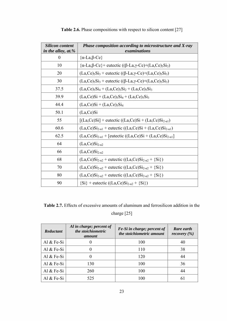
excessive amount of ferrosilicon in the charge. This fact is also shown in Table 2.6.
The addition of excess aluminum and ferrosilicon is experimentally studied by
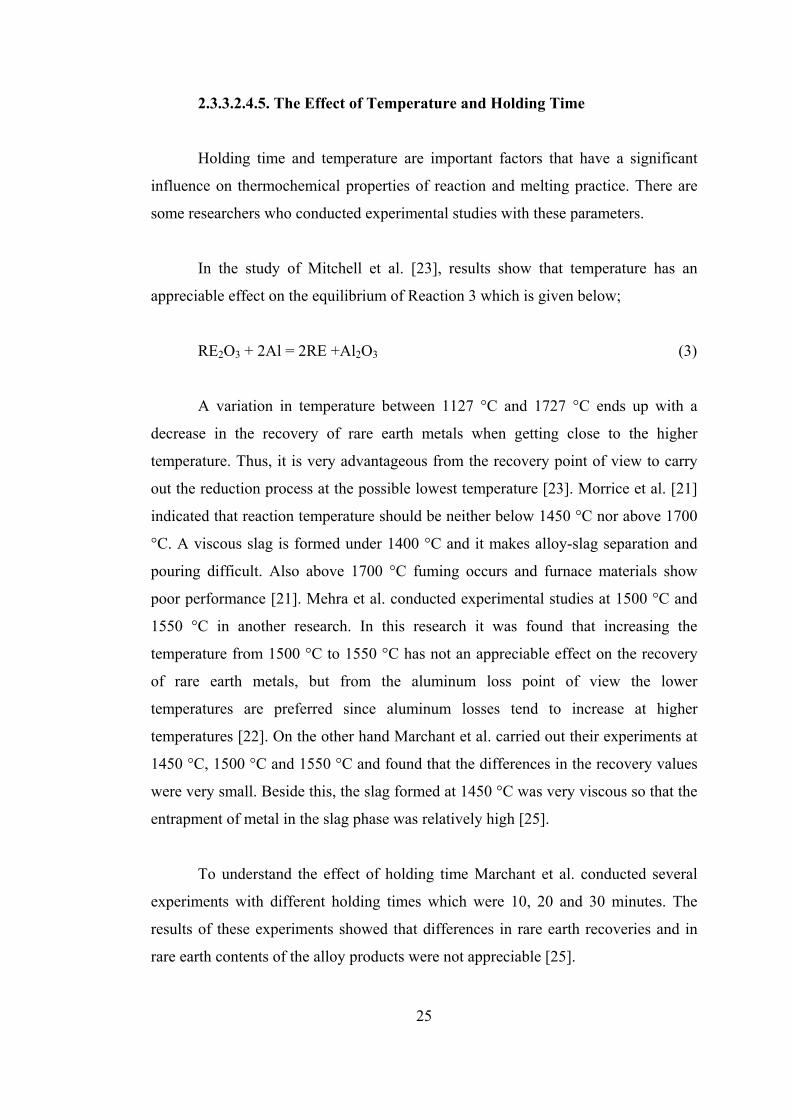
Marchant et al. [25] and the results of this study are given in Table 2.7. and these
results are in accordance with the theoretical expectations.

21
Figure 2.5. Formation energies of rare earth oxides and some other oxides vs.
Temperature [26]

22
Figure 2.6. Binary phase diagram of (50%La-50%Ce)-Si [27]
23
Table 2.6. Phase compositions with respect to silicon content [27]
Silicon content in the alloy, at.%
Phase composition according to microstructure and X-ray examinations
0 {α-La,β-Ce}
10 {α-La,β-Ce}+ eutectic ((β-La,γ-Ce)+(La,Ce)5Si3)
20 (La,Ce)5Si3 + eutectic ((β-La,γ-Ce)+(La,Ce)5Si3)
30 (La,Ce)5Si3 + eutectic ((β-La,γ-Ce)+(La,Ce)5Si3)
37.5 (La,Ce)5Si4 + (La,Ce)3Si2 + (La,Ce)5Si3
39.9 (La,Ce)Si + (La,Ce)5Si4 + (La,Ce)5Si3
44.4 (La,Ce)Si + (La,Ce)5Si4
50.1 (La,Ce)Si
55 [(La,Ce)Si] + eutectic ((La,Ce)Si + (La,Ce)Si2-α1)
60.6 (La,Ce)Si2-α1 + eutectic ((La,Ce)Si + (La,Ce)Si2-α1)
62.5 (La,Ce)Si2-α1 + [eutectic ((La,Ce)Si + (La,Ce)Si2-α1]
64 (La,Ce)Si2-α2
66 (La,Ce)Si2-α2
68 (La,Ce)Si2-α2 + eutectic ((La,Ce)Si2-α2 + {Si})
70 (La,Ce)Si2-α2 + eutectic ((La,Ce)Si2-α2 + {Si})
80 (La,Ce)Si2-α2 + eutectic ((La,Ce)Si2-α2 + {Si})
90 {Si} + eutectic ((La,Ce)Si2-α2 + {Si})
Table 2.7. Effects of excessive amounts of aluminum and ferrosilicon addition in the
charge [25]
Reductant Al in charge; percent of
the stoichiometric amount
Fe-Si in charge; percent of the stoichiometric amount
Rare earth recovery (%)
Al & Fe-Si 0 100 40 Al & Fe-Si 0 110 38 Al & Fe-Si 0 120 44 Al & Fe-Si 130 100 36 Al & Fe-Si 260 100 44 Al & Fe-Si 525 100 61

24
2.3.3.2.4.4 The Effect of Flux Additions
Flux addition provides important effects on recovery of the rare earth metals
and percentage of the rare earth metals in the produced alloy. The slag should have
some properties such as low viscosity, low melting point and high basicity in order to
achieve thermochemical advantages with the addition of flux.
Mitchell et al. [23] indicated that activity of Al2O3 should be suppressed to
prevent its reaction with the rare earth oxides and thus the rare earth metal loss in the
slag phase. It is also found by Mitchell et al. that chemical activity of Al2O3 can be
diminished gradually by a basic flux without decreasing the activity of rare earth
metals and other alloying metals. It is an important fact for the success of Mitchell’s
method that the activity of Al2O3 with the metal oxides present be suppressed so that
the reduction reaction of the rare earth oxides with Al and FeSi goes to completion.
The study shows that an excess of CaO as the flux material is important to
achieve a basic slag in order to decrease the Al2O3 activity since Al2O3 acts as an
acid. In that manner it can be said that regulating the CaO content means adjusting
the basicity of the system. According to tests that Mitchell et al. has done the Al2O3
content in the liquid flux mixture should be between about 10 and 42 percent with a
preferred percentage of about 20% [23].
Entrapment of rare earth metals in the slag phase is appreciable if the
viscosity of the slag is high especially while working with large scales of charge.
Marchant et al. studied in this case extensively and conducted experiments with
different flux compositions to produce a more fluid slag and prevent the loss of
values due to entrapment in the slag phase. They found that the amount of RE2O3
dissolved in the slag decreased with increasing CaO content and achieved the
minimum loss with the flux consisting of 94 % CaO and 6 % MgO [23,25].
25
2.3.3.2.4.5. The Effect of Temperature and Holding Time
Holding time and temperature are important factors that have a significant
influence on thermochemical properties of reaction and melting practice. There are
some researchers who conducted experimental studies with these parameters.
In the study of Mitchell et al. [23], results show that temperature has an
appreciable effect on the equilibrium of Reaction 3 which is given below;
RE2O3 + 2Al = 2RE +Al2O3 (3)
A variation in temperature between 1127 °C and 1727 °C ends up with a
decrease in the recovery of rare earth metals when getting close to the higher
temperature. Thus, it is very advantageous from the recovery point of view to carry
out the reduction process at the possible lowest temperature [23]. Morrice et al. [21]
indicated that reaction temperature should be neither below 1450 °C nor above 1700
°C. A viscous slag is formed under 1400 °C and it makes alloy-slag separation and
pouring difficult. Also above 1700 °C fuming occurs and furnace materials show
poor performance [21]. Mehra et al. conducted experimental studies at 1500 °C and
1550 °C in another research. In this research it was found that increasing the
temperature from 1500 °C to 1550 °C has not an appreciable effect on the recovery
of rare earth metals, but from the aluminum loss point of view the lower
temperatures are preferred since aluminum losses tend to increase at higher
temperatures [22]. On the other hand Marchant et al. carried out their experiments at
1450 °C, 1500 °C and 1550 °C and found that the differences in the recovery values
were very small. Beside this, the slag formed at 1450 °C was very viscous so that the
entrapment of metal in the slag phase was relatively high [25].
To understand the effect of holding time Marchant et al. conducted several
experiments with different holding times which were 10, 20 and 30 minutes. The
results of these experiments showed that differences in rare earth recoveries and in
rare earth contents of the alloy products were not appreciable [25].

26
2.3.3.2.5. Examples of Production Methods from Different Studies
The study of Mitchell et al. [23] was based on two important facts to gain
higher metal recoveries; using a highly basic flux to lower the activity of Al2O3 in the
flux and maintaining this flux at the possible lowest temperature at which the flux is
in liquid state.
The process invented by Mitchell et al. [23] was performed in an induction
furnace and it consisted of melting down a flux mixture of 90% CaF2 and 10% CaO
in a graphite crucible, adding to this mixture rare earth oxide and CaO in 1:1 ratio at
a temperature of about 1371 ˚C and as a final step adding to this mixture aluminum
and silicon in excessive amounts of the theoretically required for the reduction.
In a test carried out by Mitchell et al. [23] 8.2 kg CaF2 and 0.9 kg CaO were
melted as the first step of the process. In the second step 5 kg rare earth oxide and 5
kg CaO were charged into the melt and finally 1.8 kg Si and 2 kg Al were added as
the reducing agents. Results of this test are given in Table 2.8.
Table 2.8. Results of a test from the study of Mitchell et al. [23]
Composition of the alloy product (wt. %)
RE’s Si Fe Al
Rare earth metal
recovery (%)
54.14 23.83 1.98 15.20 85.0
Morrice et al. [21] indicated that the reactor for their process might be any
suitable one capable of generating and maintaining the reaction temperature, but
utilizing an induction furnace was advantageous. Also, they found that any crucibles
made of silicon carbide, boron nitride or graphite could be used as containers for the
reactants while emphasizing that using graphite crucible could cause the formation of
some calcium carbide.
27
It can be deduced from the study of Morrice et al. [21] that utilizing the rare
earth source and calcium oxide in the form of powder, aluminum in the form of
cuttings or turnings and ferrosilicon in the form of fragments is advantageous.
The process invented by Morrice et al. [21] consists of melting the charge
materials in the reaction crucible, holding at a desired temperature for the time period
required for completion of the reaction and pouring or tapping the melt into molds.
Also separation of the products can be accomplished by allowing the melt to freeze
and breaking the slag away from the alloy product.
In a test carried out by Morrice et al. [21] rare earth oxide ore, having 82.5%
by weight of RE2O3, in an amount of 227 grams, ferrosilicon having 25% by weight
iron, in an amount of 132 grams, aluminum metal in an amount of 68.5 grams,
calcium oxide in an amount of 263 grams and magnesium oxide in an amount of 24
grams were placed into a silicon carbide crucible and melted at 1600 ˚C in an
induction furnace. After a time period of 30 minutes, the melt was poured into a
conical mold and allowed to freeze. Separation of the slag phase was done by
breaking it away from the alloy product. The results of this test are given in Table
2.9.
Table 2.9. Results of a test from the study of Morrice et al. [21]
Composition of the alloy product (wt. %)
RE’s Si Fe Al
Rare earth metal
recovery (%)
46.0 46.0 8.9 3.2 91.5
Marchant et al. [25] conducted their tests in an induction furnace with
graphite or densified silicon carbide crucibles. Rare earth oxides prepared from
bastnasite flotation concentrates, aluminum turnings and fragments of ferrosilicon
and some flux materials such as CaO and magnesia were utilized in their process as
charge materials.

28
The charge composition of a test carried out by Marchant et al. [25] consisted
of 681 grams mixed rare earth oxides, 309 grams ferrosilicon (78% Si), 182 grams
aluminum, 681 grams CaO and 45 grams magnesia where CaO and MgO served as
the flux and added on top of the other charge materials. The charge materials were
melted and held at 1500 ˚C for 30 minutes and then the melt was poured into an iron
mold. Separation of alloy product and slag was done by allowing the melt to freeze
and breaking the slag away from the alloy product. The results of this mentioned test
are given in Table 2.10.
Table 2.10. Results of a test from the study of Marchant et al. [25]
Composition of the alloy product (wt. %)
RE’s Si Fe Al
Rare earth metal
recovery (%)
52.6 27.6 10.7 3.8 80.0
The rare earth oxide mixture containing 95% REO as the rare earth source,
commercially available 80% grade FeSi and aluminum rod scrap (>99%) as reducing
agents were used in the study of Mehra et al. [24].
Two different flux mixtures; first one containing 100% CaO and 6.5% MgO
and the second one containing 120% CaO and 165% CaF2 were utilized by Mehra et
al. [24] to increase the rare earth recovery (values are given by weight of REO). The
optimum values of temperature and holding time were found as 1500 ˚C-1550 ˚C and
30 minutes, respectively.
In a test in the presence of CaO-MgO flux the charge containing 3.4 kg REO,
25 mm pieces of FeSi in an amount of 1.8 kg and 0.91 kg Al was loaded in a 250 mm
diameter graphite crucible and covered with 3.4 kg CaO and 0.225 kg MgO. The
charge was melted at 1550 ˚C and allowed to react for 30 minutes in an induction
furnace. After completion of reaction the crucible was tilted and the product alloy
was poured into an iron mold [24].

29
In another test taken from this study in the presence of CaO-CaF2, 4.55 kg
CaF2 was melted first in a graphite crucible by utilizing an induction furnace. After
this step 2.75 kg REO and 3.3 kg CaO were added into melt to form a molten bath of
REO-CaO-CaF2. As the final step 2.8 kg FeSi and 0.7 kg aluminum in lump form
were added to the bath at 1500 ˚C and allowed to react for 30 minutes. The alloy
product was cast into an iron mold to separate it from the slag phase [24]. The results
of these two tests are given in the Table 2.11.
Table 2.11. Results of the tests from the study of Mehra et al. [24]
In the presence of CaO-MgO flux In the presence of CaO-CaF2 flux
Composition of the alloy
product (wt.%)
Composition of the alloy
product (wt.%)
RE’s Si Fe Al
RE
metal
recovery
(%) RE’s Si Fe Al
RE
metal
recovery
(%)
55.12 33.0 5.0 4.0 75.8 40.0 40.4 10.0 5.1 82.8
Turgay [4] conducted his tests in an induction furnace using graphite
crucibles. Three kinds of rare earth source were utilized in his study; one of them
was a bastnasite type preconcentrate with 23.5% REO grade, the other two sources
were rich rare earth oxide concentrates with 81.6% and 94.9% REO grades. The
experiments done with the preconcentrate gave very low rare earth recoveries.
Aluminum particles (99.9%) and ferrosilicon alloy (88% Si) as reducing agents, lime
which was obtained by calcinations of Ca(OH)2 or CaCO3, quartz of 99% purity and
fluorspar as the fluxing agents were the other charge materials of the tests carried out
by Turgay.
Turgay [4] indicated that using excessive amounts of reducing agents was a
must for obtaining a high rare earth recovery and that reaction temperature should be
kept as low as possible at which a molten and fluid slag could be obtained.

30
In a test carried out by Turgay [4], 44 grams of rich rare earth oxide
concentrate (81.6% REO), 750% of the stoichiometric amount of aluminum, 112%
of the stoichiometric amount of ferrosilicon and 43.1 grams of lime were utilized as
the charge materials. As the first step of the test the rare earth concentrate was melted
in a graphite crucible at 1550 °C, then other charge materials were added together
into the crucible and the charge was allowed to react for 30 minutes. After the
holding time, crucible was taken out of the furnace and left to cool down. Separation
of the metal and slag phases was done by breaking them by a hammer. The results of
this test are given in Table 2.12.
Table 2.12. Results of the test from the study of Turgay [4]
Composition of the alloy product (wt. %)
RE’s Si Fe Al
Rare earth metal
recovery (%)
50.1 28.1 7.7 7.4 81.1

31
CHAPTER 3
EXPERIMENTAL METHOD AND PROCEDURE
3.1. General
Optimization of the conditions of production of rare earth ferrosilicon alloy
was the main aim of this study. For this purpose, a preconcentrate was prepared from
an ore of bastnasite type which was taken from the Beylikahır-Eskişehir region of
Turkey. The following part of this chapter will be about the choice of the production
method, devices and materials which were utilized in the experiments.
3.2. Production Method
As it was mentioned in the literature survey part there are two reduction
methods to produce a rare earth ferrosilicon alloy; carbothermic reduction and
metallothermic reduction. Also it can be deduced that metallothermic reduction
yields a better recovery and a better composition of the alloy product. Submerged arc
furnace for the carbothermic reduction process was not available in the department
although there were an induction furnace and a muffle furnace which could be
utilized for the metallothermic reduction process. Also an electric arc furnace
necessitated a high amount of rare earth metal source. Since the amount of the rare
earth metal source was not enough to feed that kind of large furnace, metallothermic
reduction process was selected for this study.

32
3.3. Reduction Furnace
After selection of the reduction method, the furnaces which could be utilized
for the metallothermic reduction came under consideration. There were two kinds of
furnace that could be selected; a programmable muffle furnace and an induction
furnace. Programmable muffle furnace gave an opportunity that controlling of the
temperature with it was easier than that with the induction furnace. But utilizing the
muffle furnace made the additions to charge impossible at high temperatures.
Especially, aluminum loss due to oxidation before reduction was very important.
Because of the high heating rate and the opportunity for making the additions at high
temperatures, it was thought that utilizing an induction furnace would be more
advantageous.
3.4. Crucible
As it was mentioned in the literature survey part, materials which were not
attacked by the slag formed during the process such as graphite or silicon carbide
could be used to make crucibles.
Graphite crucibles could be machined easily and cheaply. So, it was decided
to utilize graphite crucibles although formation of some calcium carbide was
expected to take place by the reaction between the melt and graphite. It may be said
that this choice was only dictated by the availability of the crucible materials. A
schematic drawing of the crucible used is given in Figure 3.1.

33
Figure 3.1. Technical drawing of the graphite crucible and its lid

34
3.5. Charge Materials
3.5.1. Rare Earth Metal Source
A bastnasite preconcentrate which was obtained by concentration of a sample
taken from a rare earth ore body located in Beylikahır-Eskişehir region of Turkey
was used in all the experiment as the rare earth metal source.
Concentration of this ore was done by attrition scrubbing followed by
screening and desliming. For this purpose the ore sample was first ground to -10
Tyler mesh (-1.7 mm) and was subjected to attrition scrubbing with a 50% solid
concentration for one hour. After screening from 400 mesh and dilution of -400 mesh
(-38 microns), classification of the pulp by a series of hydrocyclones was done. A
fine bastnasite preconcentrate with a 23.13 % REO grade was obtained as
hydrocyclone overflow at the end of such concentration process. The composition of
the obtained preconcentrate and its XRD analysis are given in Table 3.1. and Figure
3.2., respectively. Calculation of the composition of this preconcentrate from SEM
analysis is given in Appendix A part.
Table 3.1. Composition of the preconcentrate
Compound Weight Conc. (%)
La2O3 9.11
Ce2O3 14.02
CaF2 35.44
CaCO3 7.24
SiO2 6.78
Fe2O3 7.97
BaSO4 6.12
Al2O3 2.38
P2O5 2.16
MgO 0.95

35
: Bastnasite : CaF2 : BaSO4
Figure 3.2. XRD pattern of bastnasite preconcentrate
3.5.2. Reducing Agents
3.5.2.1. Choice of Reducing Agents
There were two possible candidates as the reducing agents for the
metallothermic reduction process; calcium silicide and aluminum together with
ferrosilicon. As it was mentioned in the literature survey part, both of these
candidates were successfully used to obtain a high rare earth recovery in the previous
studies. Since the aim of this study was to produce a rare earth ferrosilicon alloy,
aluminum with ferrosilicon usage was found to be more advantageous. The high cost
of calcium silicide was also an important reason for choosing aluminum with
ferrosilicon as the reducing agent. So, in all the experiments of this study, aluminum
together with ferrosilicon was utilized as the reducing agent.

36
3.5.2.2. Aluminum
Aluminum rod pieces about 0.5-1 cm. in length and 3 mm. in diameter with
99.9 % purity were used in all the experiments as aluminum source. The reason for
using aluminum pieces rather than aluminum powder was its tendency for oxidation
before reduction reaction.
3.5.2.3. Ferrosilicon
Ferrosilicon in the range of -18 +200 mesh size (-850 +75 microns)
containing 73.23 % Si was used in all the experiments. Source of iron in the rare
earth ferrosilicon alloys produced was ferrosilicon in all of the experiments.
3.5.3. Lime
Commercially available CaO in powder form with a 99.9% grade was the
only fluxing agent utilized in all of the experiments.
3.6. Experiments
50 grams of rare earth preconcentrate was utilized for each experiment of this
study and the calculation of the other charge materials which are CaO, Al and FeSi
was done by taking this amount as the base.
At the beginning of all the experiments, 50 grams of preconcentrate was
mixed under acetone in an agate mortar with the predetermined amount of CaO.
Three spherical agglomerates were made from this mixture to prevent dusting
problem that might be encountered during the melting process. The graphite crucible
which was closed by a graphite lid was then placed into an induction furnace which
had a power output of 41 kW and a melting capacity of 4 kg aluminum and heating
process was started. At the center of the lid, there was a hole of about 1 cm in
diameter for temperature measurement which was done by an optical pyrometer
about every 1 minute.

37
After the predetermined reaction temperature was reached, the lid of the
crucible was opened and agglomerates were charged into the crucible. Aluminum
and ferrosilicon were added to crucible by a small shovel when agglomerates were
melted completely and this was taken as the start of experiment. Holding the crucible
at the reaction temperature for a predetermined time to complete the reaction was
followed by taking it out and leaving at room temperature to cool down. The day
after, crucible was broken down with a hammer for taking the produced metal and
slag phases out. Then, the products were separated from each other by carefully
breaking them with a hammer.
Metal and slag phases were weighed before preparing samples from them for
EDS analyses at the scanning electron microscope (SEM). Rare earth recoveries of
the experiments were calculated according to Equation 1 given below;
(Metal wt.).(wt%RE-metals)in metal phase (Metal wt.).(wt%RE-metals)in metal phase + (Slag wt.).(wt%RE-metals)in slag phase
X 100 (1)
Since both of the phases were not always homogeneous, samples taken for
quantitative analysis might not always represent the whole composition of the
products. So, while evaluating the results of this study it must be taken into account
that there may be small deviations from the exact values. Flow chart of the
experiments is given in Figure 3.3.

38
Figure 3.3. Flowchart of the experiments
Rare Earth Metal Source
Preparation of the Mixture
Preparation of Agglomerates Ferrosilicon Aluminum
Smelting in Induction Furnace
Cooling in Air
Breaking down the Crucible and Separation of the Products
Slag Phase Metal Phase
Weighing
EDS Analysis X-Ray Analysis
CaO

39
3.7. Experimental Variables
The optimization of conditions of production of rare earth ferrosilicon alloy
was studied using the variables given as ranges in Table 3.2.
Table 3.2. Experimental variables
Variables Range
Basicity* of the slag phase 1.3 - 1.65 - 2
Holding time (min.) 15 - 30 - 45
Temperature (°C) 1450 - 1500 - 1550
Aluminum amount in excess of the
stoichiometric amount (wt.%) 500 - 550 - 600 - 750
Ferrosilicon amount in excess of the
stoichiometric amount (wt.%) 100 - 112 - 150
CaO(wt.%) + BaO(wt.%) * Basicity = SiO2(wt.%) + Al2O3(wt.%)
Experiments were done using the combinations of the parameters given
above. The optimum reduction conditions were tried to be found.

40
CHAPTER 4
RESULTS AND DISCUSSION
4.1. General
In this chapter, results of the tests carried out with the chosen equipment and
materials using the procedure which was mentioned in the previous chapter are given
and discussed in order to understand the effects of the experimental variables on the
production of rare earth ferrosilicon alloy by reduction with aluminum together with
ferrosilicon.
4.2. Effects of the Experimental Variables
4.2.1. Effect of the Basicity of the Slag Phase
To understand the effect of the basicity of the slag phase on the rare earth
recovery, three tests were made. Basicity of the slag phase was adjusted by changing
the amount of CaO charged.
Basicity ratios of 1.3, 1.65 and 2 were obtained by utilizing 13.04 g, 17.84 g
and 22.65 g of CaO, respectively, with 50 g of rare earth preconcentrate, 3.72 g of
aluminum (600% of the stoichiometric amount) and 7.57 g of ferrosilicon (112% of
the stoichiometric amount). Aluminum and ferrosilicon additions were made at
1500°C and the charge was allowed to react for 30 minutes for each of the
experiments. Results of the experiments are given in Table 4.1. and Figure 4.1.

41
Table 4.1. The effect of the basicity of the slag phase on alloy composition and rare
earth recovery
Composition of the alloy product (wt. %) Basicity of
the slag
phase RE’s Si Fe Al
RE-metal
recovery
(%)
1.3 36.2 36.3 22.2 5.3 56.0
1.65 39.1 33.6 24.4 2.9 53.5
2.0 41.7 32.0 23.9 2.3 40.0
2.0* 43.2 31.0 23.5 2.3 39.4
* This experiment was repeated in order to see whether it was reproducible or not
Figure 4.1. RE-metal recovery vs. Basicity of the slag phase
Recovery of the rare earth metal values slightly decreased from 56.0 % to
53.5% as the basicity of the slag phase increased from 1.3 to 1.65. Further increase of
the basicity to 2 resulted in a high decrease of recovery to 40.0 %.

42
As mentioned in the literature survey part, a basic flux is necessary for
suppressing the activity of Al2O3, so that the reduction reaction of the rare earth
oxides with Al and FeSi goes to completion [23]. Also it was stated by Morrice et al.
[21] that utilizing of the graphite crucible could cause the formation of some calcium
carbide. XRD pattern which shows the formation of calcium carbide in slag phase is
given in Figure 4.2. In the same figure, CeAlO3 phase was also detected which may
have formed due to Reaction 4 which is given below. The formation of CeAlO3
resulted in low recovery of rare earths.
½ Ce2O3 + ½ Al2O3 = CeAlO3 (4)
: CaC2 : CaF2 : CeAlO3
Figure 4.2. XRD pattern of the slag phase with the basicity ratio of two
When the slag phase obtained from the experiment carried out with a slag
basicity ratio of 1.3 was investigated under SEM, it was seen that the bright areas of
SEM micrograph included high amounts of rare earths which meant that a part of the
rare earth metals might be entrapped in the slag as can be seen in Figure 4.3. It could
be said that slag phases with the basicity ratios of 1.65 and 2 were more viscous
which could cause more entrapment problem than the slag with the basicity ratio of

43
1.3, since the basicity ratios of the slag phases were adjusted by CaO addition only.
Figure 4.3. SEM micrograph of an experiment realized with a basicity ratio of 1.3.
In this manner, it can be concluded that as long as a basic and fluid slag was
obtained, basicity of the slag should be kept at a value that prevents the formation of
calcium carbide as much as possible.
4.2.2. Effect of Temperature
In order to understand the effect of temperature, at which the reduction
reaction is carried out, on the recovery of rare earth metals as alloy product three
tests were made at 1450°C, 1500°C and 1550°C.
50 grams of rare earth preconcentrate was reacted with 600 % of the
stoichiometric amount of aluminum and 112 % of the stoichiometric amount of
ferrosilicon required for reduction reaction in all of the experiments. 22.6 grams of
CaO was used as the only fluxing agent which resulted in a slag basicity ratio of 2 in

44
all the runs. The charge mixture was allowed to react in furnace for 30 minutes. The
results of these three tests are given in Table 4.2. and Figure 4.4.
Table 4.2. The effect of temperature on alloy composition and rare earth recovery
Composition of the alloy product (wt. %) Temperature
(°C) RE’s Si Fe Al
RE-metal
recovery
(%)
1450 48.1 31.9 18.2 1.8 56.0
1500 41.7 32.0 23.9 2.3 40.0
1550 24.1 37.9 33.6 4.4 21.8
0
10
20
30
40
50
60
70
80
90
100
1425 1450 1475 1500 1525 1550 1575
Temperature (°C)
RE-
Rec
over
y (%
)
Figure 4.4. RE-metal recovery vs. Reaction temperature
While temperature increased from 1450 °C to 1550 °C, recovery of the rare
earth metals as alloy product decreased continuously from 56.0 % to 21.8 %. These
results showed that the temperature at which the reduction reaction was carried out
was highly effective on the recovery of rare earth metals and the composition of

45
alloy product as mentioned by the previous workers [21, 23].
Although it is expected that higher temperatures should give better recoveries
since the viscosity of slag phase decreases with increasing temperature, the results
are not in accordance with this expectation. This fact can be explained by the
statement of Mehra et al. [22] which says that even a small decrease in reduction
temperature reduces the aluminum losses. Rate of the oxidation of aluminum before
reduction reaction increases while working at higher temperatures and results in a
higher loss of the reducing agent and therefore a lower recovery of rare earths.
Mitchell et al. [23] indicated that temperature had a large influence on the
equilibrium of Reaction 2 and carrying out the reduction at the lowest possible
temperature had an advantage on recovery of the rare earth metals from the oxides.
Morrice et al. [21] mentioned in their study that temperatures below 1400 °C
were not suitable for the reduction process because of the increasing slag viscosity.
Having CaF2 in the rare earth preconcentrate was an advantage for this study because
existence of CaF2 made it possible to decrease the temperature to 1450 °C while not
vitally increasing the slag viscosity.
It can be said that, to obtain a higher rare earth recovery and better
composition of alloy product, temperatures as low as possible which ensure a fluid
and low viscosity slag should be utilized for the reduction process.
4.2.3. Effect of Aluminum Amount in the Charge
Since aluminum was the main reducing agent utilized throughout this study,
its amount was a very important parameter for optimizing the conditions of rare earth
ferrosilicon alloy production.
To understand the effect of aluminum amount in the charge, four tests were
made with 500%, 550%, 600% and 750% of the stoichiometric amount of aluminum.

46
In all of the experiments, 50 grams of rare earth preconcentrate and 112 % of the
stoichiometric amount of ferrosilicon were used with CaO as the fluxing agent, the
amount of which was adjusted to set the basicity ratio to 1.3. Aluminum together
with ferrosilicon were added to reaction mixture at 1500 °C and allowed to react for
30 minutes. Results of these four tests are given in Table 4.3. and Figure 4.5.
Recovery of the rare earth metal values increased from 23.3 % to 56.0 % with
increasing amount of aluminum addition from 500 % to 600 % of the stoichiometric
amount. Further increment in the amount of aluminum addition to 750 % of the
stoichiometric amount resulted in a decrease of the rare earth metal recovery to
35.6%.
Table 4.3. The effect of aluminum addition on alloy composition and rare earth
recovery
Composition of the alloy product (wt. %) % Aluminum
addition of the
stoichiometric
amount RE’s Si Fe Al
RE-metal
recovery
(%)
500 23.9 37.6 36.5 2.0 23.3
550 30.3 33.7 33.2 2.8 32.3
600 36.2 36.3 22.2 5.3 56.0
750 32.1 35.7 26.5 5.7 35.6

47
0
10
20
30
40
50
60
70
80
90
100
450 500 550 600 650 700 750 800
Aluminum Amount (%)
RE-
Rec
over
y (%
)
Figure 4.5. RE-Metal recovery vs. % Aluminum addition of the stoichiometric
amount
At high temperatures, a significant amount of aluminum is oxidized before
the reduction reaction. As it was mentioned by the previous workers [21, 23], the
amount of aluminum to be charged should be in excess of the stoichiometric amount
to compensate for the aluminum losses due to oxidation.
From the aforementioned aluminum oxidation point of view, it may be
thought that rare earth metal recovery increases with increasing aluminum amount in
the charge. But it is not an exact statement since an increment of aluminum addition
amount results in a higher percentage of Al2O3 in the slag phase that leads to a higher
activity of Al2O3. So, the driving force for Reaction 2 decreases with increasing
activity of Al2O3. This fact may be shown by Equation 2.
3 RE2O3 + 15 Si + 2 Al = 6 RESi2 + 3 SiO2 + Al2O3 (2)
(2)
(aRESi2)6 . (aSiO2)3 . (aAl2O3) ∆G2 = ∆Gº2 + RT ln
(aRE2O3)3 . (aSi)15 . (aAl)2
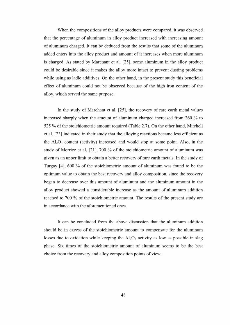
48
When the compositions of the alloy products were compared, it was observed
that the percentage of aluminum in alloy product increased with increasing amount
of aluminum charged. It can be deduced from the results that some of the aluminum
added enters into the alloy product and amount of it increases when more aluminum
is charged. As stated by Marchant et al. [25], some aluminum in the alloy product
could be desirable since it makes the alloy more intact to prevent dusting problems
while using as ladle additives. On the other hand, in the present study this beneficial
effect of aluminum could not be observed because of the high iron content of the
alloy, which served the same purpose.
In the study of Marchant et al. [25], the recovery of rare earth metal values
increased sharply when the amount of aluminum charged increased from 260 % to
525 % of the stoichiometric amount required (Table 2.7). On the other hand, Mitchell
et al. [23] indicated in their study that the alloying reactions became less efficient as
the Al2O3 content (activity) increased and would stop at some point. Also, in the
study of Morrice et al. [21], 700 % of the stoichiometric amount of aluminum was
given as an upper limit to obtain a better recovery of rare earth metals. In the study of
Turgay [4], 600 % of the stoichiometric amount of aluminum was found to be the
optimum value to obtain the best recovery and alloy composition, since the recovery
began to decrease over this amount of aluminum and the aluminum amount in the
alloy product showed a considerable increase as the amount of aluminum addition
reached to 700 % of the stoichiometric amount. The results of the present study are
in accordance with the aforementioned ones.
It can be concluded from the above discussion that the aluminum addition
should be in excess of the stoichiometric amount to compensate for the aluminum
losses due to oxidation while keeping the Al2O3 activity as low as possible in slag
phase. Six times of the stoichiometric amount of aluminum seems to be the best
choice from the recovery and alloy composition points of view.

49
4.2.4. Effect of Ferrosilicon Amount in the Charge
Amount of ferrosilicon is a very important parameter for the production of
rare earth ferrosilicon alloy since it is the source of both iron and silicon in the alloy
product and the silicon content of it serves as reducing agent together with
aluminum.
To understand the effect of ferrosilicon amount on the rare earth recovery and
alloy composition three tests were made with 100 %, 112 % and 150 % of the
stoichiometric amount of ferrosilicon. 50 grams of rare earth preconcentrate, 600 %
of the stoichiometric amount of aluminum and CaO amount of which was adjusted to
set the basicity ratio of slag phase to 1.3 were used with the predetermined amounts
of ferrosilicon. Ferrosilicon was added at 1500 °C together with aluminum and
duration was set to 30 minutes in each of the tests. Results of the tests are given in
Table 4.4. and Figure 4.6.
Rare earth metal recovery increased from 33.5 % to 56.0 % while the amount
of ferrosilicon addition increased from 100 % to 112 % of the stoichiometric amount.
Further increment in the amount of ferrosilicon addition to 150 % of the
stoichiometric amount resulted in a decrease of the rare earth metal recovery to 39.7
%.
Table 4.4. The effect of ferrosilicon addition on alloy composition and rare earth
recovery
Composition of the alloy product (wt. %) % Ferrosilicon
addition of the
stoichiometric
amount RE’s Si Fe Al
RE-metal
recovery
(%)
100 30.7 35.8 30.5 3.0 33.5
112 36.2 36.3 22.2 5.3 56.0
150 25.1 40.1 31.4 3.3 39.7

50
0
10
20
30
40
50
60
70
80
90
100
75 100 125 150 175
FeSi Amount (%)
RE-
Rec
over
y (%
)
Figure 4.6. RE-Metal recovery vs. % FeSi addition of the stoichiometric
amount
As mentioned in the literature survey part, ferrosilicon amount charged
should be in excess of the stoichiometric amount required for Reaction 2. This
certain necessity for excessive ferrosilicon was shown in Figure 2.6. and Table 2.6.
[27]. From the SiO2 activity point of view, ferrosilicon usage over 112% of the
stoichiometric amount resulted in an increase of the SiO2 activity in slag phase while
preventing the completion of Reaction 2 and decreasing the rare earth metal recovery
as alloy product.
It can be said that utilizing excess amount of ferrosilicon increases the rare
earth recovery up to a point at which increasing SiO2 activity began to decrease rare
earth recovery. The optimum ferrosilicon addition was found as 112% of the
stoichiometric amount.
4.2.5. Effect of Duration
Duration, the time period in which the reduction reaction was allowed to
occur at the reaction temperature, was one of the parameters affecting the success of
rare earth ferrosilicon alloy production.

51
To understand the effect of duration on rare earth metal recovery and alloy
composition, three tests were realized with 15, 30 and 45 minutes of duration. In all
of the runs 50 grams of rare earth preconcentrate was utilized as the rare earth metal
source. CaO amounts were adjusted to set the basicity ratio of the slag phases to two.
600 % aluminum and 112 % ferrosilicon of the stoichiometric amounts were added
into the charge which consisted of the rare earth preconcentrate and CaO at 1500°C.
Results of the tests are given in Table 4.5. and Figure 4.7.
Table 4.5. Effect of duration on alloy composition and rare earth recovery
Composition of the alloy product (wt. %) Duration (min.)
RE’s Si Fe Al
RE-metal
recovery
(%)
15 40.3 35.9 20.1 3.7 47.6
30 41.7 32.0 23.9 2.3 40.0
45 25.0 33.7 38.6 2.7 20.6
0
10
20
30
40
50
60
70
80
90
100
0 5 10 15 20 25 30 35 40 45 50
Duration (min)
RE-
Rec
over
y(%
)
Figure 4.7. RE-Metal recovery vs. Duration

52
From Figure 4.7., it is seen that rare earth metal recovery was the highest
(47.6%) with 15 minutes of duration period. Then, it showed 7.6 % decrease to
40.0% as the interval extended to 30 minutes, and on extending the duration period
further to 45 minutes, the recovery dropped sharply to 20.6 %. There was not an
appreciable difference between the alloy compositions of the tests with 15 and 30
minutes. Further extension of duration to 45 minutes resulted in a substantial
decrease of rare earth grade of alloy.
As mentioned in the experimental method and procedure part, some of the
calcium in lime reacted with the graphite crucible and formed calcium carbide.
Formation of calcium carbide decreased the basicity of the slag which resulted in
higher activity of Al2O3 and SiO2, therefore affected the reaction thermochemistry
adversely. The effect of calcium carbide formation became more pronounced at
longer time intervals, namely 30 and 45 minutes of duration period. Results of the
tests are in accordance with the studies of Morrice et al. [21] and Turgay [4] who
also mentioned about the formation of calcium carbide while using graphite
crucibles.
Apart from the results of these tests, extending the duration period over 15
minutes results in consumption of more energy and decrease in productivity, which
are economically unfavorable. 15 minutes of duration period was found to be the
optimum for completion of the reduction reaction while keeping the formation of
calcium carbide as low as possible.
4.3. Experiment Performed Under the Optimum Conditions Determined
After realizing several experiments, it was found that utilizing 600 %
aluminum of the stoichiometric amount and 112 % ferrosilicon of the stoichiometric
amount with a basicity ratio of 1.3 and a holding time of 15 minutes at 1450 °C were
advantageous for the production of rare earth ferrosilicon alloy from rare earth
preconcentrate.

53
A final experiment was conducted using the findings in order to obtain the
highest rare earth recovery. 50 grams of rare earth preconcentrate was utilized with
the optimum values of the parameters which are summarized above. Results of the
experiment are given in Table 4.6.
Table 4.6. Results of the experiment performed under the optimum conditions
Composition of the alloy product (wt. %)
RE’s Si Fe Al
RE-metal
recovery (%)
39.3 37.5 19.3 3.9 57.7
A rare earth ferrosilicon alloy with 39.3 % rare earth metal grade and 57.7 %
rare earth metal recovery was obtained at the end of this test.
4.4. Experiment Performed Using the Preconcentrate with Higher REO
Grade
After realizing the experiments with the rare earth preconcentrate containing
23.13 % REO, a preconcentrate containing 31.11 % REO was obtained by
classifying the preconcentrate by a hydrocyclone once again. The composition of the
obtained preconcentrate is given in Table 4.7. Calculation of the composition of this
preconcentrate is given in Appendix B part.
An experiment was conducted utilizing 50 grams of rare earth preconcentrate
containing 31.11 % REO with the optimum values of the parameters. Results of this
experiment are given in Table 4.8.

54
Table 4.7. Composition of the preconcentrate containing 31.11 % REO
Compound Weight Conc. (%)
La2O3 14.76
Ce2O3 16.35
CaF2 25.58
CaCO3 5.25
SiO2 7.91
Fe2O3 9.56
BaSO4 5.11
Al2O3 2.35
P2O5 1.61
MgO 1.05
Table 4.8. Results of the experiment made with the preconcentrate containing
31.11% REO
Composition of the alloy product (wt. %)
RE’s Si Fe Al
RE-metal
recovery (%)
40.4 31.2 25.0 3.4 58.1
As it can be seen from Table 4.6. and Table 4.8., the results obtained with two
different preconcentrates having 23.13% REO and 31.11% REO, respectively, were
about the same with respect to alloy composition and rare earth recovery.

55
CHAPTER 5
CONCLUSIONS
In this research work the optimization of conditions of metallothermic
reduction of rare earth preconcentrate was studied. The following conclusions were
drawn considering the experimental results:
1. As long as a basic and fluid slag was obtained, basicity of the slag should
be kept at a value that prevents the formation of calcium carbide as much as possible
since utilizing graphite crucibles cause the formation of calcium carbide.
2. To obtain a higher rare earth recovery and better composition of alloy
product, temperatures as low as possible which ensure a fluid and low viscosity slag
should be used for the reduction process. In this study, the optimum temperature of
smelting was found to be 1450 °C.
3. Aluminum amount should be in excess of the stoichiometric amount to
compensate for the aluminum losses due to oxidation while keeping the Al2O3
activity as low as possible in slag phase. 6 times of the stoichiometric amount of
aluminum seems to be the best choice from the recovery and alloy composition
points of view.
4. Utilizing the ferrosilicon in excess of the stoichiometric amount was found
to be advantageous to obtain a better rare earth metal recovery up to a point where
the increasing SiO2 activity started to reduce the rare earth metal recovery. In this
study, 112 % of the stoichiometric amount of ferrosilicon gave the highest recovery.

56
5. In order to achieve satisfactory rare earth metal recoveries, allowing the
reduction reaction of rare earth oxides to occur for 15 minutes was found to be
advantageous.
6. In order to increase rare earth metal recoveries in metallothermic reduction
of rare earth preconcentrate, reducing agents such as CaSi should be tried as future
work.

57
REFERENCES
1. A.W. Zelikman, “Metallurgy of Rare Earth Metals”, U.S. NASA and NSF
Publication, pp. 258, (1966)
2. Rare Earth Elements on the Net, http://osoon.ut.ee/~hahha/re/general.html,
January 2007
3. Rare Earths, http://www.du.edu/~jcalvert/phys/rare.htm, January 2007
4. O. Turgay, “The Optimization of Experimental Conditions for Production of
Rare Earth Ferrosilicon Alloy”, Master Thesis in Metallurgical and Materials
Engineering Department, Middle East Technical University, (2003)
5. C.K. Gupta, N. Krishnamurthy, “Extractive Metallurgy of Rare Earths”,
International Materials Review, Vol.37, No.5, pp. 197-248, (1992)
6. R. J. Callow, “The Industrial Chemistry of the Lanthanons, Yttrium, Thorium
and Uranium”, Pergamon Press., pp. 43-57, (1967)
7. Rare Earth Metals Find Interesting New Uses, http://www.arris-
intl.com/customer/Papers/remetalspaper.html, January 2007
8. Rare Earth Elements-Critical Resources of High Technology/ USGS Fact
Sheet 087-02, http://pubs.usgs.gov/fs/2002/fs087-02/, January 2007
9. B.T. Kilbourn, “A Lanthanide Lanthology”, Part I:A-L, Part II:M-Z,
Molycorp Inc., Mountain Pass, CA, USA, (1993)
58
10. B.T. Kilbourn, Kirk-Othmer Encyclopedia of Chemical Technology, “Cerium
and Cerium Compounds”, John Wiley & Sons Inc., Vol.5, pp. 729-730,
(1993)
11. E. Morrice, R. G. Knickerbocker, The Rare Earths, ”Rare-Earth Electrolytic
Metals”, John Wiley & Sons Inc., pp. 126-144, (1961)
12. W. H. Trethewey, J. R. Jackman, Ferroalloys and Other Additives to Liquid
Iron and Steel, “Trends in Rare–Earth Metal Consumption for Steel
Applications in the 1980’s”, ASTM STP 739, American Society for Testing
of Materials, pp. 99-109, (1981)
13. R. Kiessling, N. Lange, Non-metallic Inclusions in Steel, 2nd Edition, Metals
Society, London, (1978)
14. Ferroalloys & Alloying Additives Online Handbook - Cerium & Rare Earths,
http://www.shieldalloy.com/ceriumpage.html, January 2007
15. N. E. Topp,”The Chemistry of the Rare Earth Elements”, Elsevier Publishing
Comp., pp. 144-145, (1965)
16. V. S. Arunachalam, S. Ramachandran, Science and Technology of Rare Earth
Materials, “Rare Earths in Steel Technology”, Academic Press, pp. 415-434,
(1980)
17. J.O. Staggers, “Rare Earth Metal Silicide Alloys”, U.S. Patent No. 4.018.597,
(1977)
18. C. H. Sump, “Method for the Production of Alloys”, U.S. Patent No.
3.264.093, (1966)
19. W. Bungardt, R. Kallenbach, “Process of Making Rare Earth Metals and
Silicon Alloys”, U.S. Patent No. 3.440.040, (1969)

59
20. R. B. Hechenroeder, “Methods of Making Reactive Metal Silicide”, U.S.
Patent No. 3.953.579, (1976)
21. E. Morrice, J.D. Marchant, “Process for the Preparation of Rare Earth Silicon
Alloys”, U.S. Patent No. 4.135.921, (1979)
22. O.K. Mehra, S. Singh, J.S. Sehra, T.S. Krishnan, D.K. Bose, C.K. Bose,
“Extractive Metallurgy of Rare Earths – Developmental Work at the Bhabha
Atomic Research Center”, Materials Science Forum, Vol. 30, pp. 73-88,
(1988)
23. A. Mitchell, J.R. Goldsmith, J.M. Gray, “Preparation of Rare Earth and Other
Metal Alloys Containing Aluminum and Silicon”, U.S. Patent No. 4.108.645,
(1978)
24. D.K. Bose, O.K. Mehra, C.K. Gupta, “Preparation of Rare Earth Silicon Iron
Alloy by Metallothermic Reduction”, Journal of the Less Common Metals,
Vol.110, pp. 239-242, (1985)
25. J.D. Marchant, E. Morrice, B.P. Herve, M.M. Wong, “Preparing Rare Earth
Silicon Iron Aluminum Alloys”, U.S.B.M, R.I. 8445, (1980)
26. G. Borzone, R. Raggio, R. Ferro, “Thermochemistry and Reactivitiy of Rare
Earth Metals”, PCCP, No.1, pp.1487-1500, (1999)
27. M.V. Bulanova, P.N. Zheltov, K.A. Meleshevich, “Lanthanum-Cerium-
Silicon System”, Journal of Alloys and Compounds, Vol. 347, pp.149-155,
(2002)
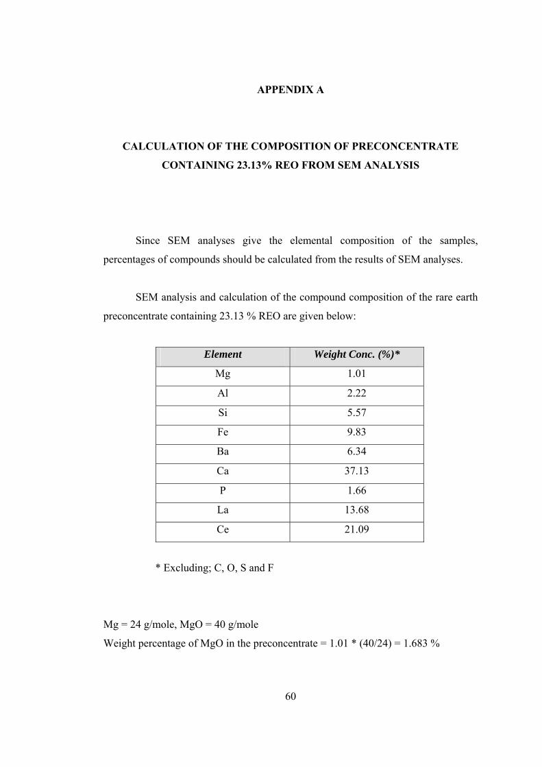
60
APPENDIX A
CALCULATION OF THE COMPOSITION OF PRECONCENTRATE
CONTAINING 23.13% REO FROM SEM ANALYSIS
Since SEM analyses give the elemental composition of the samples,
percentages of compounds should be calculated from the results of SEM analyses.
SEM analysis and calculation of the compound composition of the rare earth
preconcentrate containing 23.13 % REO are given below:
Element Weight Conc. (%)*
Mg 1.01
Al 2.22
Si 5.57
Fe 9.83
Ba 6.34
Ca 37.13
P 1.66
La 13.68
Ce 21.09
* Excluding; C, O, S and F
Mg = 24 g/mole, MgO = 40 g/mole
Weight percentage of MgO in the preconcentrate = 1.01 * (40/24) = 1.683 %

61
Si = 28 g/mole, SiO2 = 60 g/mole
Weight percentage of SiO2 in the preconcentrate = 5.57 * (60/28) = 11.935 %
Al = 27 g/mole, Al2O3 = 102 g/mole
Weight percentage of Al2O3 in the preconcentrate = 2.22 * (102/54) = 4.193 %
Fe = 56 g/mole, Fe2O3 = 160 g/mole
Weight percentage of Fe2O3 in the preconcentrate = 9.83 * (160/112) = 14.042 %
Ba = 137 g/mole, BaSO4 = 233 g/mole
Weight percentage of BaSO4 in the preconcentrate = 6.34 * (233/137) = 10.782 %
P = 31 g/mole, P2O5 = 142 g/mole
Weight percentage of P2O5 in the preconcentrate = 1.66 * (142/62) = 3.802 %
It was assumed that 13.8 % of the amount of Ca occurred as CaCO3 and the
rest which is 86.2 % of the amount of Ca occurred as CaF2;
Ca = 40 g/mole, CaCO3 = 100 g/mole, CaF2 = 78 g/mole
Weight percentage of CaCO3 in the preconcentrate = 37.13 * (13.8/100) * (100/40) =
12.81 %
Weight percentage of CaF2 in the preconcentrate = 37.13 * (86.2/100) * (78/40) =
62.411 %
La = 139 g/mole, LaFCO3 = 218 g/mole
Weight percentage of LaFCO3 in the preconcentrate = 13.68 * (218/139) = 21.455 %
Ce = 140 g/mole, CeFCO3 = 219 g/mole
Weight percentage of CeFCO3 in the preconcentrate = 21.09 * (219/140) = 32.99 %
The sum of these percentage values = 176.103

62
Since the summation of percentage values does not equal to 100, they must be
multiplied with a correction factor which is 100/176.103.
Corrected weight percentages of compounds are given in following table:
Compound Weight Conc. (%)
LaFCO3 12.18
CeFCO3 18.73
CaF2 35.44
CaCO3 7.24
SiO2 6.78
Fe2O3 7.97
BaSO4 6.12
Al2O3 2.38
P2O5 2.16
MgO 0.95
Calculation of REO grade of the preconcentrate;
La = 139 g/mole, LaFCO3 = 218 g/mole, La2O3 = 326 g/mole
Weight percentage of La2O3 in the preconcentrate = 12.18 * (139/218) * (326/278) =
9.11 %
Ce = 140 g/mole, CeFCO3 = 219 g/mole, Ce2O3 = 328 g/mole
Weight percentage of Ce2O3 in the preconcentrate = 18.73 * (140/219) * (328/280) =
14.02 %
Total REO grade of the preconcentrate = 9.11 + 14.02 = 23.13 %

63
APPENDIX B
CALCULATION OF THE COMPOSITION OF PRECONCENTRATE
CONTAINING 31.11% REO FROM SEM ANALYSIS
SEM analysis and calculation of the compound composition of the rare earth
preconcentrate containing 31.11 % REO are given below:
Element Weight Conc. (%)*
Mg 1.08
Al 2.16
Si 6.40
Fe 11.59
Ba 5.20
Ca 26.36
P 1.22
La 21.81
Ce 24.18
* Excluding; C, O, S and F
Mg = 24 g/mole, MgO = 40 g/mole
Weight percentage of MgO in the preconcentrate = 1.08 * (40/24) = 1.8 %
Si = 28 g/mole, SiO2 = 60 g/mole
Weight percentage of SiO2 in the preconcentrate = 6.4 * (60/28) = 13.714 %

64
Al = 27 g/mole, Al2O3 = 102 g/mole
Weight percentage of Al2O3 in the preconcentrate = 2.16 * (102/54) = 4.08 %
Fe = 56 g/mole, Fe2O3 = 160 g/mole
Weight percentage of Fe2O3 in the preconcentrate = 11.59 * (160/112) = 16.557 %
Ba = 137 g/mole, BaSO4 = 233 g/mole
Weight percentage of BaSO4 in the preconcentrate = 5.2 * (233/137) = 8.843 %
P = 31 g/mole, P2O5 = 142 g/mole
Weight percentage of P2O5 in the preconcentrate = 1.22 * (142/62) = 2.794 %
It was assumed that 13.8 % of the amount of Ca occurred as CaCO3 and the
rest which is 86.2 % of the amount of Ca occurred as CaF2;
Ca = 40 g/mole, CaCO3 = 100 g/mole, CaF2 = 78 g/mole
Weight percentage of CaCO3 in the preconcentrate = 26.36 * (13.8/100) * (100/40) =
9.094 %
Weight percentage of CaF2 in the preconcentrate = 26.36 * (86.2/100) * (78/40) =
44.308 %
La = 139 g/mole, LaFCO3 = 218 g/mole
Weight percentage of LaFCO3 in the preconcentrate = 21.81 * (218/139) = 34.205 %
Ce = 140 g/mole, CeFCO3 = 219 g/mole
Weight percentage of CeFCO3 in the preconcentrate = 24.18 * (219/140) = 37.824 %
The sum of these percentage values = 173.219
Since the summation of percentage values does not equal to 100, they must be
multiplied with a correction factor which is 100/173.219.

65
Corrected weight percentages of compounds are given in following table:
Compound Weight Conc. (%)
LaFCO3 19.75
CeFCO3 21.84
CaF2 25.58
CaCO3 5.25
SiO2 7.91
Fe2O3 9.56
BaSO4 5.11
Al2O3 2.35
P2O5 1.61
MgO 1.05
Calculation of REO grade of the preconcentrate;
La = 139 g/mole, LaFCO3 = 218 g/mole, La2O3 = 326 g/mole
Weight percentage of La2O3 in the preconcentrate = 19.75 * (139/218) * (326/278) =
14.76 %
Ce = 140 g/mole, CeFCO3 = 219 g/mole, Ce2O3 = 328 g/mole
Weight percentage of Ce2O3 in the preconcentrate = 21.84 * (140/219) * (328/280) =
16.35 %
Total REO grade of the preconcentrate = 14.76 + 16.35 = 31.11 %