optimization of a low noise hydraulic piston pump - …€¦ · optimization of a low noise...
TRANSCRIPT
Case Histories Newsletter EnginSoft Year 11 n°4 - 30
Optimization of a low noise hydraulic piston pumpMinimize the noise emission while maintaining the same level of performance in a pump
The use of compact axial piston pumps of the swashplate type as input power source for modern hydraulic circuitry is common, nowadays, on both fixed and mobile applications. Beside the constant focus on pump efficiency and performance improvements, within the last few years significant attention has grown on pump noise reduction, especially for electrically powered systems as for example injection molding machines.The objective of this project was to take a standard pump (MVP60, Figure 1) with a maximum displacement of about 84 cc/rev and to minimize the noise emission, while maintaining same levels of performance.
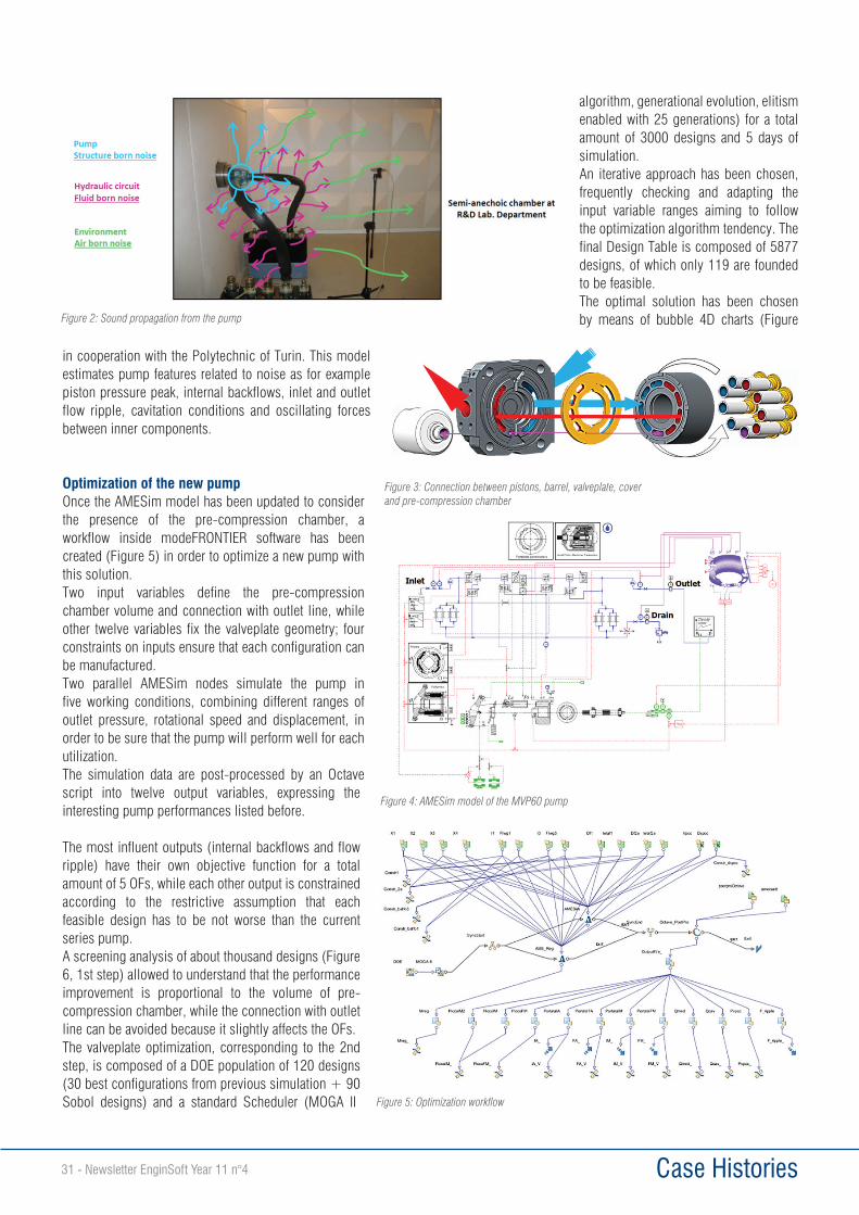
New technologyIt is well known that pump noise mainly comes from pressure fluctuations in the hydraulic circuit (fluid-borne noise) and large alternating forces inside the pump, both of which leading to the structure vibration (structure-borne noise) and the sound propagation on surroundings (air-borne noise, Figure 2).
On axial piston pumps of the swashplate type one solution that can virtually break down the flow ripple, and the pressure fluctuations in the hydraulic circuit arising from it, is the use of a pre-compression volume: it consists of an additional oil chamber able to pre-compress the fluid inside each piston before it is delivered to the pressure line.In order to achieve the prospective benefits of this device, that are the reduction of backflows from the outlet line and the decrease of
outlet flowrate peaks, a proper connection between components (Figure 3) must be designed to synchronize the external chamber recharging phase.A key design feature for an effective result is a proper delivery timing, which is defined by the geometry of the pump valveplate: it decides when and how to connect each pumping piston to external ports and, further complicated, to the pre-compression chamber.In Casappa R&D Department one simulation tool able to predict the pump functioning is the 1D circuital model depicted in Figure 4, developed in LMS Imagine.Lab AMESim environment
Figure 1: MVP series axial piston pump
Case Histories31 - Newsletter EnginSoft Year 11 n°4
in cooperation with the Polytechnic of Turin. This model estimates pump features related to noise as for example piston pressure peak, internal backflows, inlet and outlet flow ripple, cavitation conditions and oscillating forces between inner components.
Optimization of the new pumpOnce the AMESim model has been updated to consider the presence of the pre-compression chamber, a workflow inside modeFRONTIER software has been created (Figure 5) in order to optimize a new pump with this solution. Two input variables define the pre-compression chamber volume and connection with outlet line, while other twelve variables fix the valveplate geometry; four constraints on inputs ensure that each configuration can be manufactured.Two parallel AMESim nodes simulate the pump in five working conditions, combining different ranges of outlet pressure, rotational speed and displacement, in order to be sure that the pump will perform well for each utilization.The simulation data are post-processed by an Octave script into twelve output variables, expressing the interesting pump performances listed before.
The most influent outputs (internal backflows and flow ripple) have their own objective function for a total amount of 5 OFs, while each other output is constrained according to the restrictive assumption that each feasible design has to be not worse than the current series pump.A screening analysis of about thousand designs (Figure 6, 1st step) allowed to understand that the performance improvement is proportional to the volume of pre-compression chamber, while the connection with outlet line can be avoided because it slightly affects the OFs.The valveplate optimization, corresponding to the 2nd step, is composed of a DOE population of 120 designs (30 best configurations from previous simulation + 90 Sobol designs) and a standard Scheduler (MOGA II
algorithm, generational evolution, elitism enabled with 25 generations) for a total amount of 3000 designs and 5 days of simulation. An iterative approach has been chosen, frequently checking and adapting the input variable ranges aiming to follow the optimization algorithm tendency. The final Design Table is composed of 5877 designs, of which only 119 are founded to be feasible.The optimal solution has been chosen by means of bubble 4D charts (Figure Figure 2: Sound propagation from the pump
Figure 3: Connection between pistons, barrel, valveplate, cover and pre-compression chamber
Figure 4: AMESim model of the MVP60 pump
Figure 5: Optimization workflow
Case Histories Newsletter EnginSoft Year 11 n°4 - 32
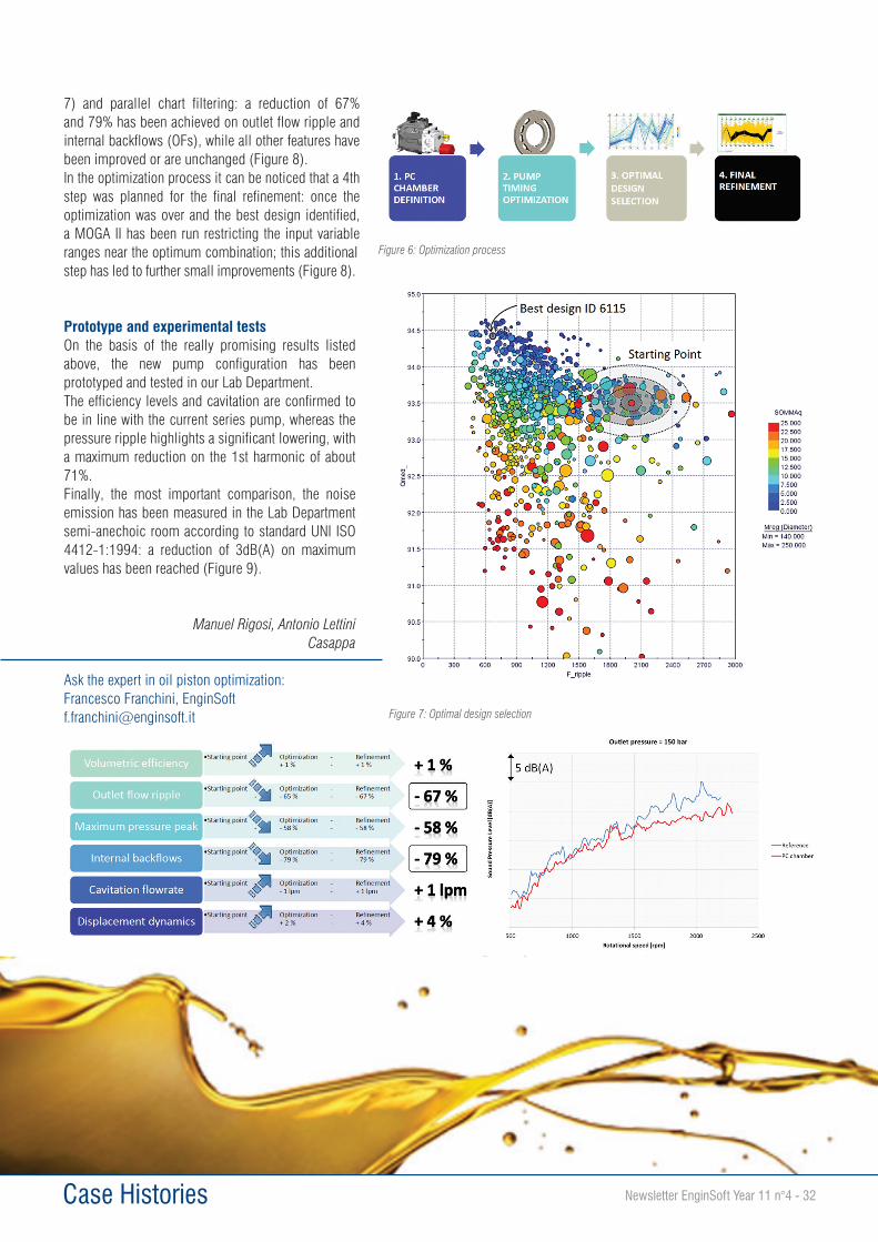
7) and parallel chart filtering: a reduction of 67% and 79% has been achieved on outlet flow ripple and internal backflows (OFs), while all other features have been improved or are unchanged (Figure 8).In the optimization process it can be noticed that a 4th step was planned for the final refinement: once the optimization was over and the best design identified, a MOGA II has been run restricting the input variable ranges near the optimum combination; this additional step has led to further small improvements (Figure 8).
Prototype and experimental testsOn the basis of the really promising results listed above, the new pump configuration has been prototyped and tested in our Lab Department. The efficiency levels and cavitation are confirmed to be in line with the current series pump, whereas the pressure ripple highlights a significant lowering, with a maximum reduction on the 1st harmonic of about 71%.Finally, the most important comparison, the noise emission has been measured in the Lab Department semi-anechoic room according to standard UNI ISO 4412-1:1994: a reduction of 3dB(A) on maximum values has been reached (Figure 9).
Manuel Rigosi, Antonio LettiniCasappa
Ask the expert in oil piston optimization:Francesco Franchini, EnginSoft [email protected] Figure 7: Optimal design selection
Figure 8: Final results Figure 9: Sound pressure level comparison
Figure 6: Optimization process