axial piston pump - p.s. hydraulicpshydraulic.com.my/pdf/piston pump pv 063 -270.pdf · axial...
TRANSCRIPT
aerospaceclimate controlelectromechanicalfiltrationfluid & gas handlinghydraulicspneumaticsprocess controlsealing & shielding
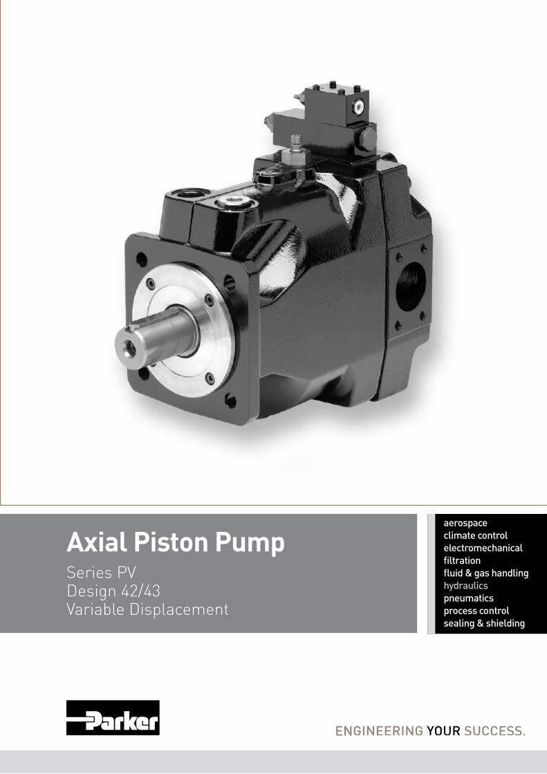
Axial Piston PumpSeries PV Design 42/43Variable Displacement
Hydraulic Pumps, VariableSeries PV
Catalogue HY02-8001/UK
5-5- 2 Parker Hannifin CorporationHydraulics Group
Catalogue HY30-3243/UK. 07/2008
Contents
Contents Page 5-5-
Introduction .....................................................................................................3
Ordering Code Preferred Program .................................................................4
Noise Levels ...................................................................................................8
Efficiency and Case Drain Flows ....................................................................9
Dimensions ...................................................................................................11
Mounting kits ................................................................................................17
Pump combinations
Thru Drive, Shaft Load Limitations .....................................................18
Compensators
Compensators Dimensions ................................................................19
Pressure Compensators ....................................................................23
Load-Sensing Compensators.............................................................24
Power Compensators .........................................................................25
Power Compensators, Diagrams........................................................26
Electronic Module PQDXXA (digital) ..................................................28
General Installation Information .........................................................29
Accessories Compensator .................................................................30
Hydraulic Pumps, VariableSeries PV
Catalogue HY02-8001/UK
5-5- 3 Parker Hannifin CorporationHydraulics Group
5
Technical Features• Lownoiselevel• Fastresponse• Service-friendly• Highself-primingspeed• Compactdesign• Thrudrivefor100%nominaltorque
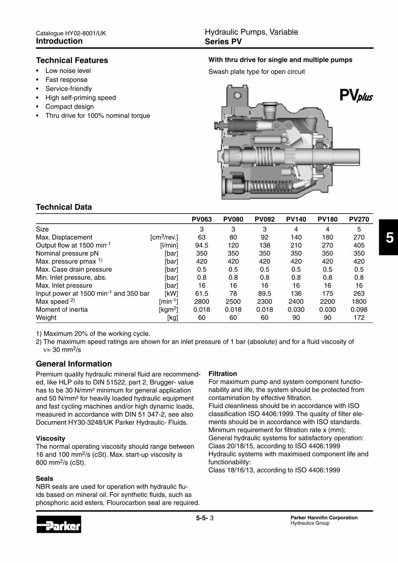
Technical Data PV063 PV080 PV092 PV140 PV180 PV270Size 3 3 3 4 4 5 Max. Displacement [cm3/rev.] 63 80 92 140 180 270 Output flow at 1500 min-1 [l/min] 94.5 120 138 210 270 405 Nominal pressure pN [bar] 350 350 350 350 350 350 Max. pressure pmax 1) [bar] 420 420 420 420 420 420 Max. Case drain pressure [bar] 0.5 0.5 0.5 0.5 0.5 0.5 Min. Inlet pressure, abs. [bar] 0.8 0.8 0.8 0.8 0.8 0.8 Max. Inlet pressure [bar] 16 16 16 16 16 16 Input power at 1500 min-1 and 350 bar [kW] 61.5 78 89.5 136 175 263 Max speed 2) [min-1] 2800 2500 2300 2400 2200 1800 Moment of inertia [kgm2] 0.018 0.018 0.018 0.030 0.030 0.098 Weight [kg] 60 60 60 90 90 172
1)Maximum20%oftheworkingcycle.2) The maximum speed ratings are shown for an inlet pressure of 1 bar (absolute) and for a fluid viscosity of
ν= 30 mm2/s
General InformationPremiumqualityhydraulicmineralfluidarerecommend-ed, like HLP oils to DIN 51522, part 2, Brugger- value has to be 30 N/mm² minimum for general application and50N/mm²forheavilyloadedhydraulicequipmentand fast cycling machines and/or high dynamic loads, measured in accordance with DIN 51 347-2, see also Document HY30-3248/UK Parker Hydraulic- Fluids.
ViscosityThe normal operating viscosity should range between 16 and 100 mm2/s (cSt). Max. start-up viscosity is 800 mm2/s (cSt).
SealsNBR seals are used for operation with hydraulic flu-ids based on mineral oil. For synthetic fluids, such as phosphoricacidesters,Flourocarbonsealarerequired.
FiltrationFor maximum pump and system component functio-nability and life, the system should be protected from contamination by effective filtration.Fluid cleanliness should be in accordance with ISO classificationISO4406:1999.Thequalityoffilterele-ments should be in accordance with ISO standards.Minimumrequirementforfiltrationratex(mm);General hydraulic systems for satisfactory operation: Class 20/18/15, according to ISO 4406:1999Hydraulic systems with maximised component life and functionability:Class 18/16/13, according to ISO 4406:1999
With thru drive for single and multiple pumps
Swash plate type for open circuit
Introduction
Hydraulic Pumps, VariableSeries PV
Catalogue HY02-8001/UK
5-5- 4 Parker Hannifin CorporationHydraulics Group
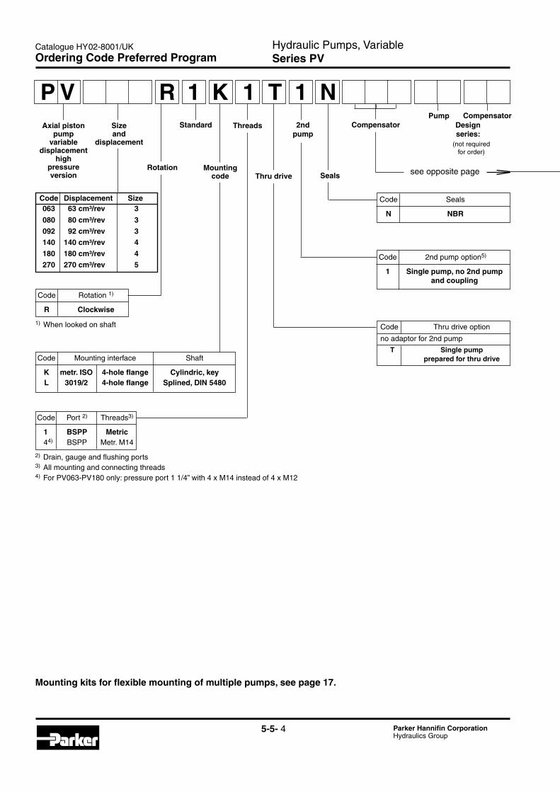
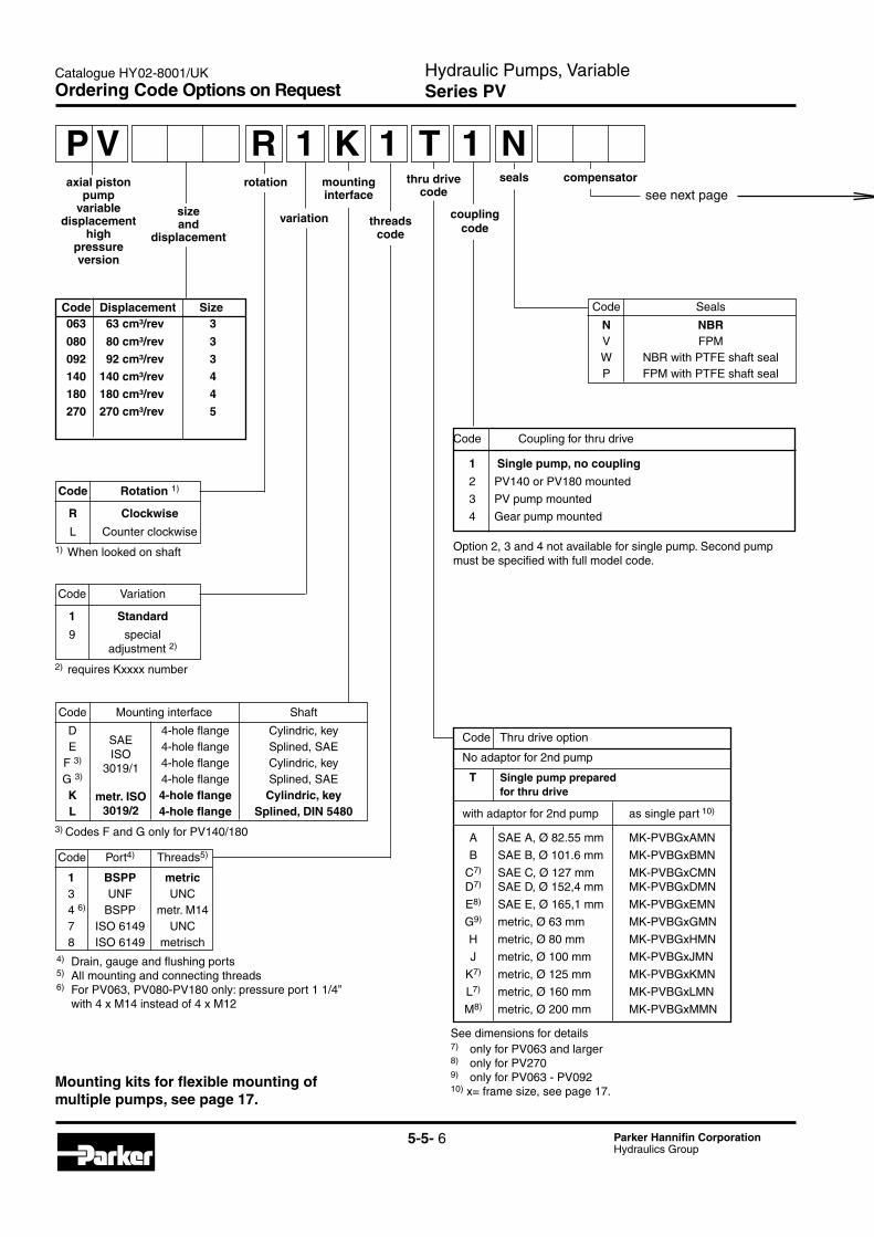
Ordering Code Preferred Program
Code Rotation 1)
R Clockwise
1) When looked on shaft
Seals
Axial piston pump
variable displacement
highpressureversion
Size and
displacement
2ndpump
Compensator
see opposite page
Standard Threads Designseries:
Mountingcode Thru drive
Rotation
2) Drain, gauge and flushing ports3) All mounting and connecting threads4) For PV063-PV180 only: pressure port 1 1/4” with 4 x M14 instead of 4 x M12
CompensatorPump
(notrequiredfor order)
Code Mounting interface Shaft
K metr. ISO 4-hole flange Cylindric, key L 3019/2 4-hole flange Splined, DIN 5480
Code Port 2) Threads3)
1 BSPP Metric 44) BSPP Metr. M14
Code Seals
N NBR
Code 2nd pump option5)
1 Single pump, no 2nd pump and coupling
Code Thru drive option
no adaptor for 2nd pump
T Single pump prepared for thru drive
P V 1R K 1 T 1 N
Code Displacement Size 063 63 cm³/rev 3
080 80 cm³/rev 3 092 92 cm³/rev 3 140 140 cm³/rev 4 180 180 cm³/rev 4 270 270 cm³/rev 5
Mounting kits for flexible mounting of multiple pumps, see page 17.

Hydraulic Pumps, VariableSeries PV
Catalogue HY02-8001/UK
5-5- 5 Parker Hannifin CorporationHydraulics Group
5
Ordering Code Preferred Program
Function
L Power compensator C Power compensator and load-sensing
Variation
A NG6 interface top side
B No pressure compensation
C Adjustable pressure compensation
Power compensator
Code Displacement Compensator option
063 140 180 270 Nom. power [kW] Nom. torque- 092 at 1500 min-1 [Nm]
G 11 71 H 15 97 K 18.5 120 M 22 142 S 30 195 T 37 240 U 45 290 W 55 355 Y 75 485 Z 90 585 2 110 715 3 132 850
Standard Pressure Compensator Code Compensator options 0 0 1 Without compensator F D S 10 - 140 bar, spindle + lock nut F H S 40 - 210 bar, spindle + lock nut F W S 70 - 350 bar, spindle + lock nut Remote Compensator options F R Remote pressure compensator F F Load-Sensing compensator Variations for Remote Compensator C External pressure pilot 8)
1 NG6/D03 interface top side P Pilot valve PVAC1P* mounted
Note:
Compensator differential ∆p is factory pre-set to:
remote compensators, power control 15 ± 1 bar
load sensing comp. (not power control) 10 ± 1 bar
Code Compensator style
electro hydraulic control
F P V closed loop displacement control only, no pres-sure compensation
U P closed loop proportional displacement control with pressure compensation
compensator version
R pilot operated pressure control, NG6 interface
K version UPR, with proportional pilot valve type PVACRE..35 mounted
M version UPK, with pressure sensor for closed loop pressure and power control
Hydraulic Pumps, VariableSeries PV
Catalogue HY02-8001/UK
5-5- 6 Parker Hannifin CorporationHydraulics Group
Code Seals
N NBR V FPM W NBR with PTFE shaft seal P FPM with PTFE shaft seal
Code Variation
1 Standard
9 special adjustment 2)
Code Rotation 1)
R Clockwise
L Counter clockwise1) When looked on shaft
2)requiresKxxxxnumber
Code Port4) Threads5)
1 BSPP metric 3 UNF UNC 4 6) BSPP metr. M14 7 ISO 6149 UNC 8 ISO 6149 metrisch4) Drain, gauge and flushing ports5) All mounting and connecting threads6) For PV063, PV080-PV180 only: pressure port 1 1/4” with 4 x M14 instead of 4 x M12
Code Mounting interface Shaft
D 4-hole flange Cylindric, key E 4-hole flange Splined, SAE F 3) 4-hole flange Cylindric, key G 3) 4-hole flange Splined, SAE K 4-hole flange Cylindric, key L 4-hole flange Splined, DIN 5480
SAEISO
3019/1
metr. ISO3019/2
Code Displacement Size 063 63 cm³/rev 3
080 80 cm³/rev 3
092 92 cm³/rev 3 140 140 cm³/rev 4 180 180 cm³/rev 4 270 270 cm³/rev 5
Code Thru drive option
No adaptor for 2nd pump
T Single pump prepared for thru drive
with adaptor for 2nd pump as single part 10)
A SAE A, Ø 82.55 mm MK-PVBGxAMN
B SAE B, Ø 101.6 mm MK-PVBGxBMN
C7) SAE C, Ø 127 mm MK-PVBGxCMN
D7) SAE D, Ø 152,4 mm MK-PVBGxDMN
E8) SAE E, Ø 165,1 mm MK-PVBGxEMN
G9) metric, Ø 63 mm MK-PVBGxGMN
H metric, Ø 80 mm MK-PVBGxHMN
J metric, Ø 100 mm MK-PVBGxJMN
K7) metric, Ø 125 mm MK-PVBGxKMN
L7) metric, Ø 160 mm MK-PVBGxLMN
M8) metric, Ø 200 mm MK-PVBGxMMN
See dimensions for details7) only for PV063 and larger 8) only for PV270 9) only for PV063 - PV092 10) x= frame size, see page 17.
axial piston pump
variable displacement
highpressureversion
P Vmounting interface
1 K TR 1 1 Ncompensator
see next page
variation threadscode
coupling code
thru drivecode
size and
displacement
rotation seals
3) Codes F and G only for PV140/180
Ordering Code Options on Request
Mounting kits for flexible mounting of multiple pumps, see page 17.
Code Coupling for thru drive
1 Single pump, no coupling
2 PV140 or PV180 mounted
3 PV pump mounted
4 Gear pump mounted
Option 2, 3 and 4 not available for single pump. Second pump must be specified with full model code.
Hydraulic Pumps, VariableSeries PV
Catalogue HY02-8001/UK
5-5- 7 Parker Hannifin CorporationHydraulics Group
5
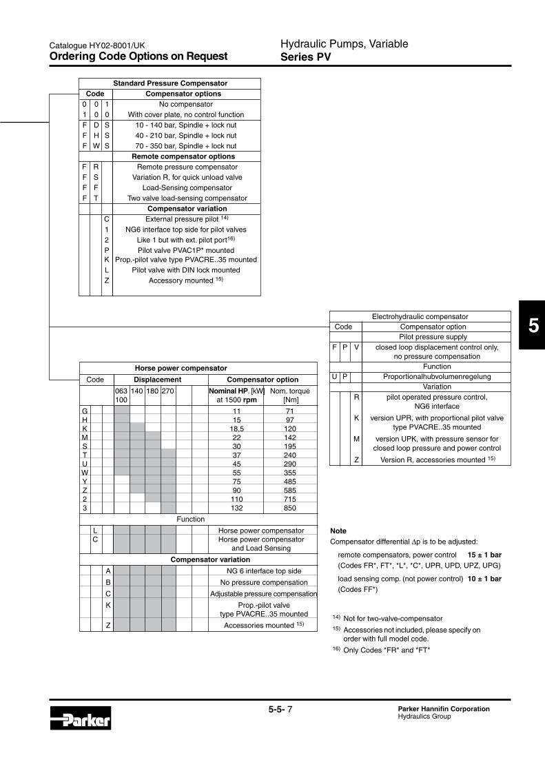
Function
L Horse power compensator C Horse power compensator and Load Sensing
Compensator variation
A NG 6 interface top side
B No pressure compensation
C Adjustable pressure compensation
K Prop.-pilot valve type PVACRE..35 mounted
Z Accessories mounted 15)
Horse power compensator
Code Displacement Compensator option
063 140 180 270 Nominal HP.[kW] Nom.torque 100 at 1500 rpm [Nm]
G 11 71 H 15 97 K 18,5 120 M 22 142 S 30 195 T 37 240 U 45 290 W 55 355 Y 75 485 Z 90 585 2 110 715 3 132 850
14) Not for two-valve-compensator15) Accessories not included, please specify on
order with full model code.16) Only Codes *FR* and *FT*
NoteCompensator differential ∆p is to be adjusted:
remote compensators, power control 15 ± 1 bar (Codes FR*, FT*, *L*, *C*, UPR, UPD, UPZ, UPG)
load sensing comp. (not power control) 10 ± 1 bar (Codes FF*)
Standard Pressure Compensator Code Compensator options 0 0 1 No compensator 1 0 0 With cover plate, no control function F D S 10 - 140 bar, Spindle + lock nut F H S 40 - 210 bar, Spindle + lock nut F W S 70 - 350 bar, Spindle + lock nut Remote compensator options F R Remote pressure compensatorF S VariationR,forquickunloadvalve F F Load-Sensing compensator F T Two valve load-sensing compensator Compensator variation C External pressure pilot 14)
1 NG6 interface top side for pilot valves 2 Like 1 but with ext. pilot port16)
P Pilot valve PVAC1P* mounted K Prop.-pilot valve type PVACRE..35 mounted L Pilot valve with DIN lock mounted Z Accessory mounted 15)
Electrohydraulic compensator Code Compensator option Pilot pressure supply F P V closed loop displacement control only, no pressure compensation Function U P Proportionalhubvolumenregelung Variation R pilot operated pressure control, NG6 interface
K version UPR, with proportional pilot valve type PVACRE..35 mounted
M version UPK, with pressure sensor for closed loop pressure and power control
Z Version R, accessories mounted 15)
Ordering Code Options on Request
Hydraulic Pumps, VariableSeries PV
Catalogue HY02-8001/UK
5-5- 8 Parker Hannifin CorporationHydraulics Group
PV140
PV180PV063 - PV092
PV270
70
60
520 200100 300
70
80
600 200100 300
70
80
600 200100 300
70
80
600 200100 300
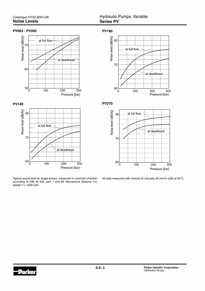
Typical sound level for single pumps, measured in unechoic chamber according to DIN 45 635, part 1 and 26. Microphone distance 1m;speed: n = 1500 rpm.
All data measured with mineral oil viscosity 30 mm²/s (cSt) at 50°C.
Noise Levels
Pressure [bar]Pressure [bar]
Pressure [bar] Pressure [bar]
at deadhead
at deadhead
at deadhead
at deadhead
at full flow
at full flow
at full flow
at full flowN
oise
leve
l [dB
(A)]
Noi
se le
vel [
dB(A
)]N
oise
leve
l [dB
(A)]
Noi
se le
vel [
dB(A
)]
Hydraulic Pumps, VariableSeries PV
Catalogue HY02-8001/UK
5-5- 9 Parker Hannifin CorporationHydraulics Group
5Case drain flows PV063-092
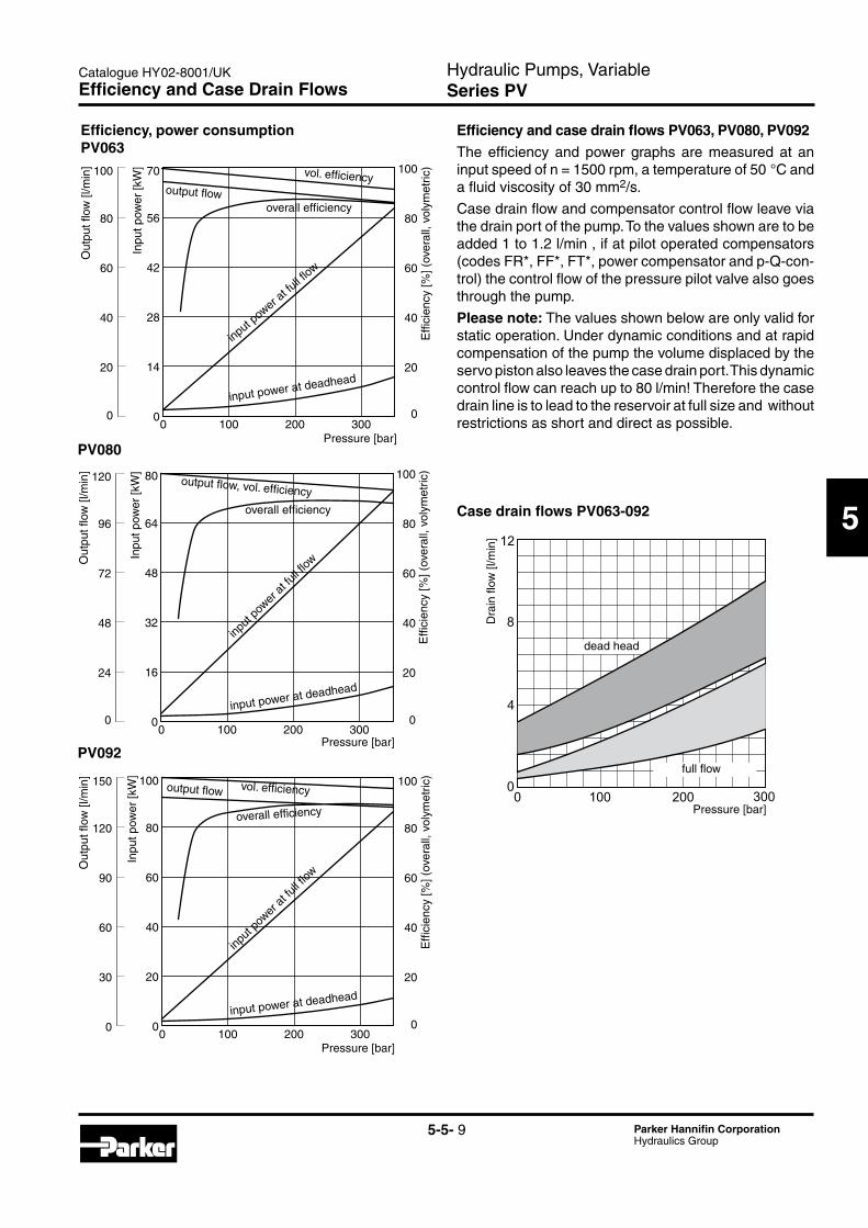
Efficiency, power consumptionPV063
Efficiency and case drain flows PV063, PV080, PV092The efficiency and power graphs are measured at an input speed of n = 1500 rpm, a temperature of 50 °C and a fluid viscosity of 30 mm2/s.
Case drain flow and compensator control flow leave via the drain port of the pump. To the values shown are to be added 1 to 1.2 l/min , if at pilot operated compensators (codes FR*, FF*, FT*, power compensator and p-Q-con-trol) the control flow of the pressure pilot valve also goes through the pump.
Please note: The values shown below are only valid for static operation. Under dynamic conditions and at rapid compensation of the pump the volume displaced by the servo piston also leaves the case drain port. This dynamic control flow can reach up to 80 l/min! Therefore the case drain line is to lead to the reservoir at full size and without restrictions as short and direct as possible.
14
0
28
42
56
70
0 100 200 3000
20
40
60
80
100
0
20
40
60
80
100
16
0
32
48
64
80
0 100 200 3000
20
40
60
80
100
0
24
48
72
96
120
20
0
40
60
80
100
0 100 200 3000
20
40
60
80
100
0
30
60
90
120
150
12
8
4
00 100 200 300
PV080
PV092
Efficiency and Case Drain Flows
Pressure [bar]
Pressure [bar]
Pressure [bar]
full flow
dead head
Dra
in fl
ow [l
/min
]
Pressure [bar]
Out
put fl
ow [l
/min
]O
utpu
t flow
[l/m
in]
Out
put fl
ow [l
/min
]
Inpu
t pow
er [k
W]
Inpu
t pow
er [k
W]
Inpu
t pow
er [k
W]
vol. efficiency
vol. efficiency
overall efficiency
overall efficiency
overall efficiency
input pow
er at fu
ll flow
input
power
at fu
ll flow
input
power
at fu
ll flow
input power at deadhead
input power at deadhead
input power at deadhead
output flow
output flow, vol. efficiency
output flow
Effi
cien
cy[%
](ov
eral
l,vo
lym
etric
)E
ffici
ency
[%](
over
all,
voly
met
ric)
Effi
cien
cy[%
](ov
eral
l,vo
lym
etric
)
Hydraulic Pumps, VariableSeries PV
Catalogue HY02-8001/UK
5-5- 10 Parker Hannifin CorporationHydraulics Group
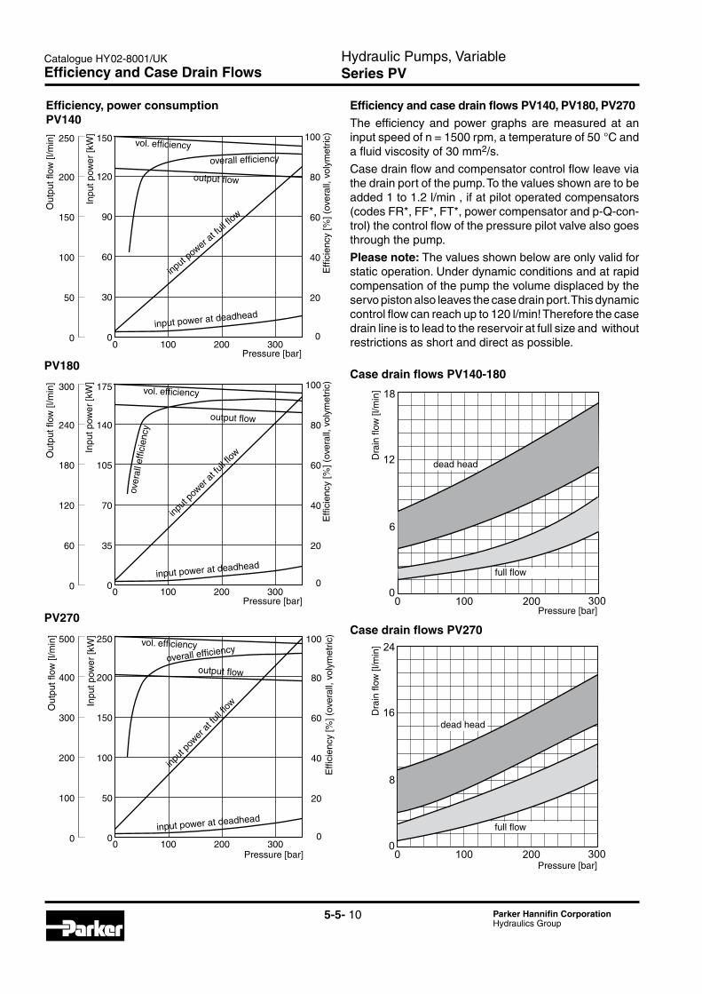
Efficiency and case drain flows PV140, PV180, PV270The efficiency and power graphs are measured at an input speed of n = 1500 rpm, a temperature of 50 °C and a fluid viscosity of 30 mm2/s.
Case drain flow and compensator control flow leave via the drain port of the pump. To the values shown are to be added 1 to 1.2 l/min , if at pilot operated compensators (codes FR*, FF*, FT*, power compensator and p-Q-con-trol) the control flow of the pressure pilot valve also goes through the pump.
Please note: The values shown below are only valid for static operation. Under dynamic conditions and at rapid compensation of the pump the volume displaced by the servo piston also leaves the case drain port. This dynamic control flow can reach up to 120 l/min! Therefore the case drain line is to lead to the reservoir at full size and without restrictions as short and direct as possible.
Efficiency, power consumptionPV140
Case drain flows PV140-180
30
0
60
90
120
150
0 100 200 3000
20
40
60
80
100
0
50
100
150
200
250
35
0
70
105
140
175
0 100 200 3000
20
40
60
80
100
0
60
120
180
240
300
50
0
100
150
200
250
0 100 200 3000
20
40
60
80
100
0
100
200
300
400
500
18
12
6
00 100 200 300
24
16
8
00 100 200 300
PV180
PV270Case drain flows PV270
Efficiency and Case Drain Flows
Pressure [bar]
Pressure [bar]
Pressure [bar]
Out
put fl
ow [l
/min
]O
utpu
t flow
[l/m
in]
Out
put fl
ow [l
/min
]
Inpu
t pow
er [k
W]
Inpu
t pow
er [k
W]
Inpu
t pow
er [k
W]
vol. efficiency
vol. efficiency
vol. efficiency
overall efficiency
over
all e
ffici
ency
overall efficiency
input pow
er at fu
ll flow
input
pow
er a
t full
flow
input
pow
er a
t full
flow
input power at deadhead
input power at deadhead
input power at deadhead
output flow
output flow
output flow
Effi
cien
cy[%
](ov
eral
l,vo
lym
etric
)E
ffici
ency
[%](
over
all,
voly
met
ric)
Effi
cien
cy[%
](ov
eral
l,vo
lym
etric
)
Pressure [bar]
Pressure [bar]
full flow
full flow
dead head
dead head
Dra
in fl
ow [l
/min
]D
rain
flow
[l/m
in]
Hydraulic Pumps, VariableSeries PV
Catalogue HY02-8001/UK
5-5- 11 Parker Hannifin CorporationHydraulics Group
5
50
77.8
66.632
56
Ø160 h8
h8
252192 36
18
20043-0.25
26
86 238
121
78
9
10
99243.5
20
287
max. 308
31
31
196
Ø40 k6 Ø160
181
135
120
200max. 133
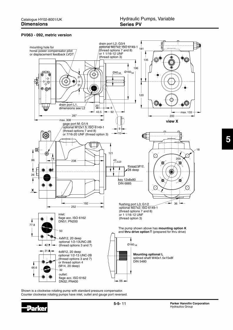
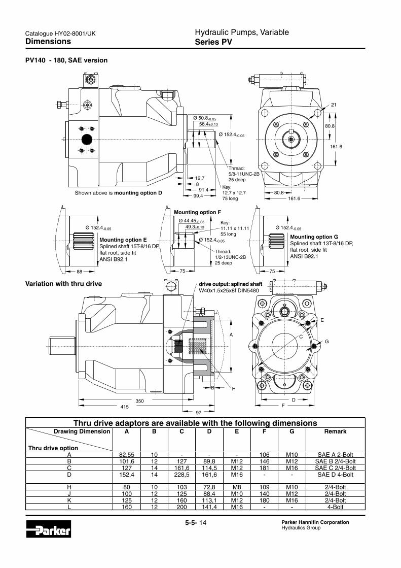
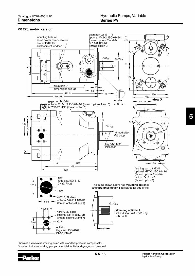
PV063 - 092, metric version
Dimensions
mounting hole for horse power compensator pilotor displacement feedback LVDT
drain port L1,dimensions see L2
drainportL2;G3/4optionalM27x2;ISO6149-1(thread options 7 and 8)or 1 1/16-12 UNF(thread option 3)
view XgageportM;G1/4optionalM12x1.5;ISO6149-1(thread options 7 and 8)or 7/16-20 UNF (thread option 3)
key 12x8x80DIN 6885
thread M12,28 deep
flushingportL3;G1/2optionalM27x2;ISO6149-1(thread options 7 and 8)or 1 1/16-12 UNF(thread option 3)
outlet:flage acc. ISO 6162DN32;PN400
inlet:flage acc. ISO 6162DN51;PN200
4xM12, 20 deepoptional 1/2-13 UNC-2B(thread options 3 and 7)or thread option 4(M14, 20 deep)
4xM12, 20 deepoptional 1/2-13UNC-2B(thread options 3 and 7)
Mounting optional Lsplined shaft W40x1.5x15x8fDIN 5480
The pump shown above has mounting option Kand thru drive option T (prepared for thru drive)
Shown is a clockwise rotating pump with standard pressure compensator. Counter clockwise rotating pumps have inlet, outlet and gauge port reversed.
Hydraulic Pumps, VariableSeries PV
Catalogue HY02-8001/UK
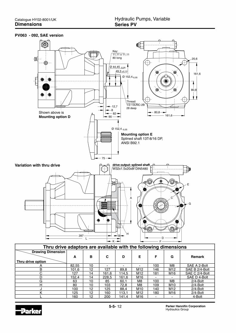
5-5- 12 Parker Hannifin CorporationHydraulics Group
287
C
D
E
F
G
A
BL
K
H
Variation with thru drive
Dimensions
Thru drive adaptors are available with the following dimensionsDrawing Dimension
Thru drive optionA B C D E F G Remark
A 82,55 10 - - - 100 M8 SAE A 2-BoltB 101,6 12 127 89,8 M12 146 M12 SAE B 2/4-BoltC 127 14 161,6 114,5 M12 181 M16 SAE C 2/4-BoltD 152,4 14 228,5 161,6 M16 - - SAE D 4-BoltG 63 10 85 60,1 M8 100 M8 2/4-BoltH 80 10 103 72,8 M8 109 M10 2/4-BoltJ 100 12 125 88,4 M10 140 M12 2/4-BoltK 125 12 160 113,1 M12 180 M16 2/4-BoltL 160 12 200 141,4 M16 - - 4-Bolt
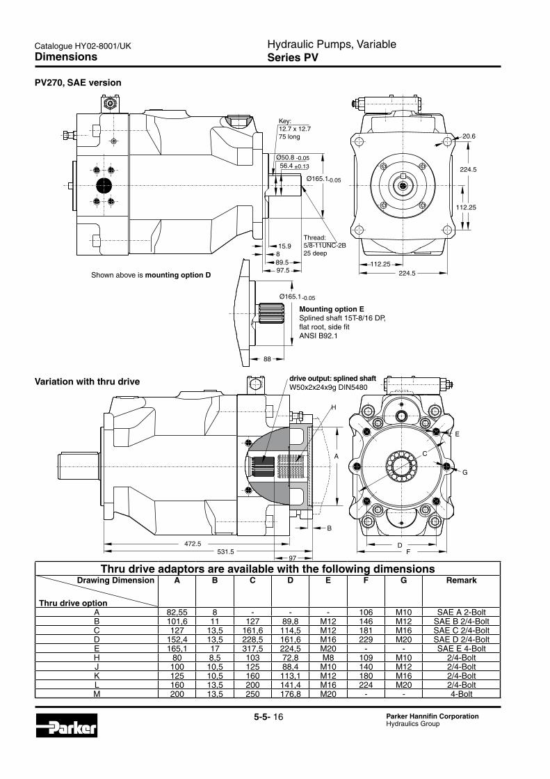
PV063 - 092, SAE version
Key:11,11 x 11,1180 long
Thread:1/2-13UNC-2B28 deep
Shown above is Mounting option D
Mounting option ESplined shaft 13T-8/16 DP, ANSI B92.1
drive output: splined shaftW32x1.5x20x8f DIN5480
Hydraulic Pumps, VariableSeries PV
Catalogue HY02-8001/UK
5-5- 13 Parker Hannifin CorporationHydraulics Group
5
910
204
158
145
200max. 133
200
Ø 160h8
78
31.8
66.6 32
6488.9
50.8
283
233
105106
53.5-0.25
147
X
992
Ø 50k6
Ø 160h8
200
35
35
350max. 385
48
40
20
18
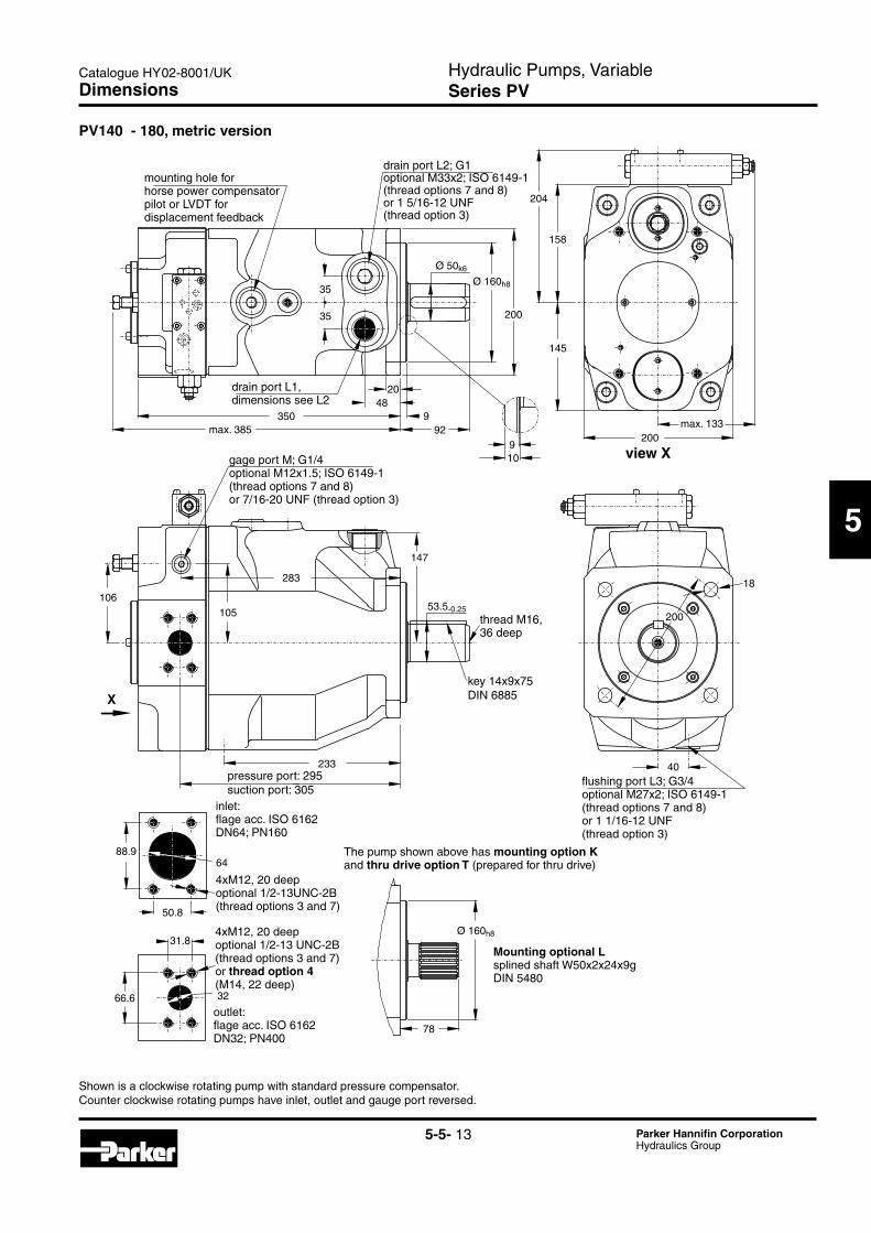
PV140 - 180, metric version
Dimensions
mounting hole for horse power compensator pilot or LVDT fordisplacement feedback
drain port L1,dimensions see L2
drainportL2;G1optionalM33x2;ISO6149-1(thread options 7 and 8)or 1 5/16-12 UNF(thread option 3)
view XgageportM;G1/4optionalM12x1.5;ISO6149-1(thread options 7 and 8)or 7/16-20 UNF (thread option 3)
key 14x9x75DIN 6885
thread M16,36 deep
flushingportL3;G3/4optionalM27x2;ISO6149-1(thread options 7 and 8)or 1 1/16-12 UNF(thread option 3)
outlet:flage acc. ISO 6162DN32;PN400
inlet:flage acc. ISO 6162DN64;PN160
4xM12, 20 deepoptional 1/2-13 UNC-2B(thread options 3 and 7)or thread option 4(M14, 22 deep)
4xM12, 20 deepoptional 1/2-13UNC-2B(thread options 3 and 7)
Mounting optional Lsplined shaft W50x2x24x9gDIN 5480
The pump shown above has mounting option Kand thru drive option T (prepared for thru drive)
Shown is a clockwise rotating pump with standard pressure compensator. Counter clockwise rotating pumps have inlet, outlet and gauge port reversed.
pressure port: 295suction port: 305
Hydraulic Pumps, VariableSeries PV
Catalogue HY02-8001/UK
5-5- 14 Parker Hannifin CorporationHydraulics Group
Variation with thru drive
350415
97
B
A
FD
C
E
G
H
Dimensions
Thru drive adaptors are available with the following dimensionsDrawing Dimension
Thru drive option
A B C D E F G Remark
A 82,55 10 - - - 106 M10 SAE A 2-BoltB 101,6 12 127 89,8 M12 146 M12 SAE B 2/4-BoltC 127 14 161,6 114,5 M12 181 M16 SAE C 2/4-BoltD 152,4 14 228,5 161,6 M16 - - SAE D 4-Bolt
H 80 10 103 72,8 M8 109 M10 2/4-BoltJ 100 12 125 88,4 M10 140 M12 2/4-BoltK 125 12 160 113,1 M12 180 M16 2/4-BoltL 160 12 200 141,4 M16 - - 4-Bolt
PV140 - 180, SAE version
Key:11.11 x 11.1155 long
Key:12.7 x 12.775 long
Thread:5/8-11UNC-2B25 deep
Thread:1/2-13UNC-2B25 deep
Mounting option ESplined shaft 15T-8/16 DP, flat root, side fit ANSI B92.1
Mounting option GSplined shaft 13T-8/16 DP, flat root, side fit ANSI B92.1
Mounting option F
drive output: splined shaftW40x1.5x25x8f DIN5480
Shown above is mounting option D
Hydraulic Pumps, VariableSeries PV
Catalogue HY02-8001/UK
5-5- 15 Parker Hannifin CorporationHydraulics Group
5
PV 270, metric version
Ø88
120.7
69.8
36.5
79.4 Ø38
80
Ø200h8
128
110
306378
403
172
69 -0.25
max. 133
22
250
50
910
265250
176
184
230
1159
25
60
max. 510472.5
45
45
Ø65 Ø200k6 h8
Dimensions
mounting hole for horse power compensator pilot or LVDT fordisplacement feedback
drain port L1,dimensions see L2
drainportL2;G11/4optionalM42x2;ISO6149-1(thread options 7 and 8)or 1 5/8-12 UNF(thread option 3)
view XgageportM;G1/4optionalM12x1.5;ISO6149-1(threadoptions7and8)or 7/16-20 UNF (thread option 3)
key 18x11x98DIN 6885
thread M20,42 deep
flushingportL3;G3/4optionalM27x2;ISO6149-1(thread options 7 and 8)or 1 1/16-12 UNF(thread option 3)
outlet:flage acc. ISO 6162DN38;PN400
inlet:flage acc. ISO 6162DN89;PN25
4xM16, 32 deepoptional 5/8-11 UNC-2B(thread options 3 and 7)
4xM16, 32 deepoptional 5/8-11 UNC-2B(thread options 3 and 7)
Mounting optional Lsplined shaft W60x2x28x9gDIN 5480
The pump shown above has mounting option Kand thru drive option T (prepared for thru drive)
Shown is a clockwise rotating pump with standard pressure compensator. Counter clockwise rotating pumps have inlet, outlet and gauge port reversed.
Hydraulic Pumps, VariableSeries PV
Catalogue HY02-8001/UK
5-5- 16 Parker Hannifin CorporationHydraulics Group
H
A
B
531.597
DF
E
G
C
472.5
Variation with thru drive
Dimensions
Thru drive adaptors are available with the following dimensionsDrawing Dimension
Thru drive option
A B C D E F G Remark
A 82,55 8 - - - 106 M10 SAE A 2-BoltB 101,6 11 127 89,8 M12 146 M12 SAE B 2/4-BoltC 127 13,5 161,6 114,5 M12 181 M16 SAE C 2/4-BoltD 152,4 13,5 228,5 161,6 M16 229 M20 SAE D 2/4-BoltE 165,1 17 317,5 224,5 M20 - - SAE E 4-BoltH 80 8,5 103 72,8 M8 109 M10 2/4-BoltJ 100 10,5 125 88,4 M10 140 M12 2/4-BoltK 125 10,5 160 113,1 M12 180 M16 2/4-BoltL 160 13,5 200 141,4 M16 224 M20 2/4-BoltM 200 13,5 250 176,8 M20 - - 4-Bolt
88
Ø165.1
224.5112.25
112.25
224.5
20.6
15.9889.597.5
Ø165.1
Ø50.856.4
-0.05
-0.05
-0.05
±0.13
PV270, SAE version
Key:12.7 x 12.775 long
Thread:5/8-11UNC-2B25 deep
Mounting option ESplined shaft 15T-8/16 DP, flat root, side fit ANSI B92.1
drive output: splined shaftW50x2x24x9g DIN5480
Shown above is mounting option D
Hydraulic Pumps, VariableSeries PV
Catalogue HY02-8001/UK
5-5- 17 Parker Hannifin CorporationHydraulics Group
5
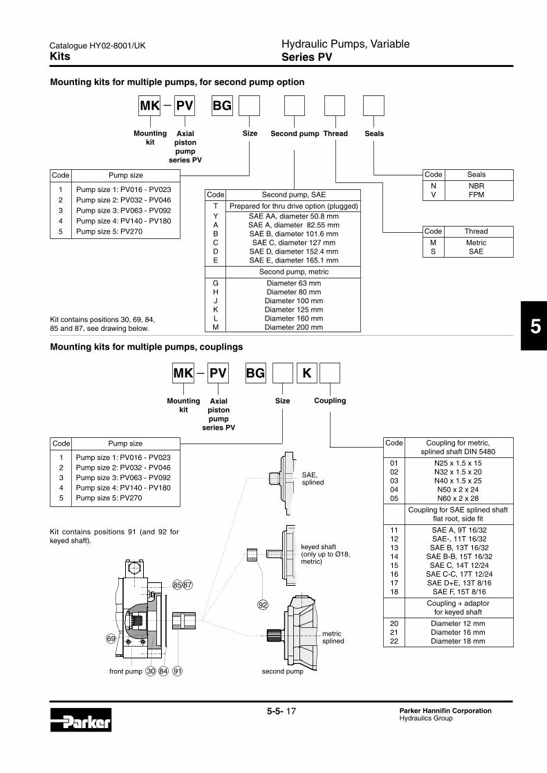
Code Second pump, SAE
T Prepared for thru drive option (plugged) Y SAE AA, diameter 50.8 mm A SAE A, diameter 82.55 mm B SAE B, diameter 101.6 mm C SAE C, diameter 127,mm D SAE D, diameter 152.4 mm E SAE E, diameter 165.1 mm
Second pump, metric
G Diameter 63 mm H Diameter 80 mm J Diameter 100 mm K Diameter 125 mm L Diameter 160 mm M Diameter 200 mm
SealsSecond pump Thread
PVMK
Axial piston pump
series PV
BG
Size
Code Seals
N NBR V FPM
30 84
69
91
85 87
92
Mounting kit
Code Thread
M Metric S SAE
PVMK
Axial piston pump
series PV
BG
SizeMounting kit
Coupling
Mounting kits for multiple pumps, for second pump option
Mounting kits for multiple pumps, couplings
Code Pump size
1 Pump size 1: PV016 - PV023 2 Pump size 2: PV032 - PV046 3 Pump size 3: PV063 - PV092 4 Pump size 4: PV140 - PV180 5 Pump size 5: PV270
Kit contains positions 30, 69, 84, 85 and 87, see drawing below.
Code Pump size
1 Pump size 1: PV016 - PV023 2 Pump size 2: PV032 - PV046 3 Pump size 3: PV063 - PV092 4 Pump size 4: PV140 - PV180 5 Pump size 5: PV270
Code Coupling for metric, splined shaft DIN 5480
01 N25 x 1.5 x 15 02 N32 x 1.5 x 20 03 N40 x 1.5 x 25 04 N50 x 2 x 24 05 N60 x 2 x 28
Coupling for SAE splined shaft flat root, side fit
11 SAE A, 9T 16/32 12 SAE-, 11T 16/32 13 SAE B, 13T 16/32 14 SAE B-B, 15T 16/32 15 SAE C, 14T 12/24 16 SAE C-C, 17T 12/24 17 SAE D+E, 13T 8/16 18 SAE F, 15T 8/16
Coupling + adaptor for keyed shaft
20 Diameter 12 mm 21 Diameter 16 mm 22 Diameter 18 mm
Kit contains positions 91 (and 92 for keyed shaft).
K
Kits
SAE,splined
keyed shaft(only up to Ø18,metric)
metricsplined
second pumpfront pump
Hydraulic Pumps, VariableSeries PV
Catalogue HY02-8001/UK
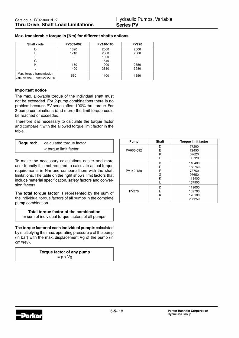
5-5- 18 Parker Hannifin CorporationHydraulics Group
Pump Shaft Torque limit factor
D 77280 PV063-092 E 72450 K 67620 L 83720
D 118400 E 158760 PV140-180 F 78750 G 97650 K 113400 L 157500
D 119000 PV270 E 159700 K 170100 L 236250
Shaft code PV063-092 PV140-180 PV270
D 1320 2000 2000 E 1218 2680 2680 F -- 1320 -- G -- 1640 -- K 1150 1900 2850 L 1400 2650 3980
Max.torquetransmission 560 1100 1650
cap. for rear mounted pump
Important noticeThemax.allowable torqueof the individualshaftmustnot be exceeded. For 2-pump combinations there is no problembecausePVseriesoffers100%thrutorque.For3-pumpcombinations(andmore)thelimittorquecouldbe reached or exceeded.
Thereforeit isnecessarytocalculatethetorquefactorandcompareitwiththeallowedtorquelimitfactorinthetable.
Required: calculatedtorquefactor
<torquelimitfactor
To make the necessary calculations easier and more userfriendlyitisnotrequiredtocalculateactualtorquerequirements inNmandcompare themwith theshaftlimitations. The table on the right shows limit factors that include material specification, safety factors and conver-sion factors.
Max. transferable torque in [Nm] for different shafts options
Total torque factor of the combination=sumofindividualtorquefactorsofallpumps
Torque factor of any pump = p x Vg
The total torque factor is represented by the sum of theindividualtorquefactorsofallpumpsinthecompletepump combination.
The torque factor of each individual pump is calculated by multiplying the max. operating pressure p of the pump (in bar) with the max. displacement Vg of the pump (in cm³/rev).
Thru Drive, Shaft Load Limitations
Hydraulic Pumps, VariableSeries PV
Catalogue HY02-8001/UK
5-5- 19 Parker Hannifin CorporationHydraulics Group
5
Compensators Dimensions
45
73
37,5
43,5172 46
41
45
P
A
T
43,5
P
A
T
172
72
45
4146
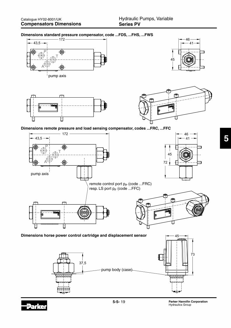
Dimensions standard pressure compensator, code ...FDS, ...FHS, ...FWS
pump axis
Dimensions horse power control cartridge and displacement sensor
pump axis
remote control port pP (code ...FRC) resp. LS port pF (code ...FFC)
Dimensions remote pressure and load sensing compensator, codes ...FRC, ...FFC
pump body (case)
Hydraulic Pumps, VariableSeries PV
Catalogue HY02-8001/UK
5-5- 20 Parker Hannifin CorporationHydraulics Group
Compensators Dimensions
4553
4182
87
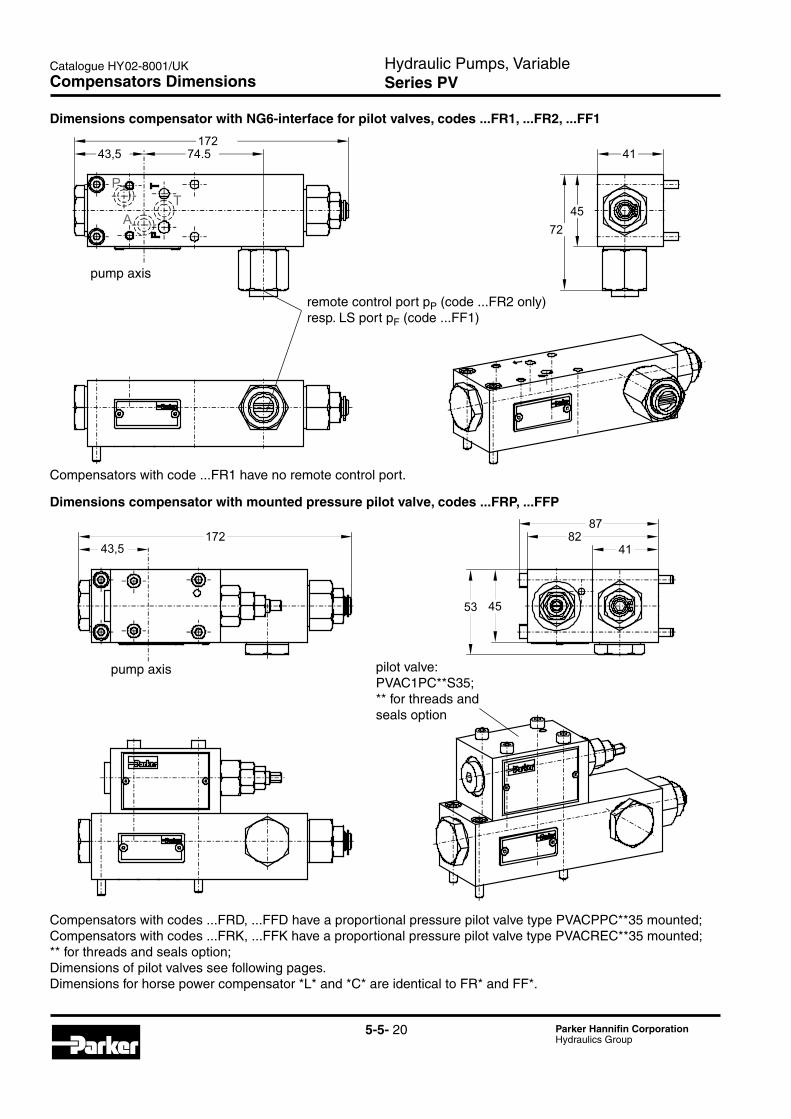
43,5172
41
4572
43,5172
74.5
P
AT
Dimensions compensator with NG6-interface for pilot valves, codes ...FR1, ...FR2, ...FF1
pump axis
Compensators with code ...FR1 have no remote control port.
Dimensions compensator with mounted pressure pilot valve, codes ...FRP, ...FFP
pump axis
remote control port pP (code ...FR2 only) resp. LS port pF (code ...FF1)
pilot valve: PVAC1PC**S35; ** for threads and seals option
Compensatorswithcodes...FRD,...FFDhaveaproportionalpressurepilotvalvetypePVACPPC**35mounted;Compensatorswithcodes...FRK,...FFKhaveaproportionalpressurepilotvalvetypePVACREC**35mounted;**forthreadsandsealsoption;Dimensions of pilot valves see following pages.Dimensions for horse power compensator *L* and *C* are identical to FR* and FF*.
Hydraulic Pumps, VariableSeries PV
Catalogue HY02-8001/UK
5-5- 21 Parker Hannifin CorporationHydraulics Group
5
Compensators Dimensions
82
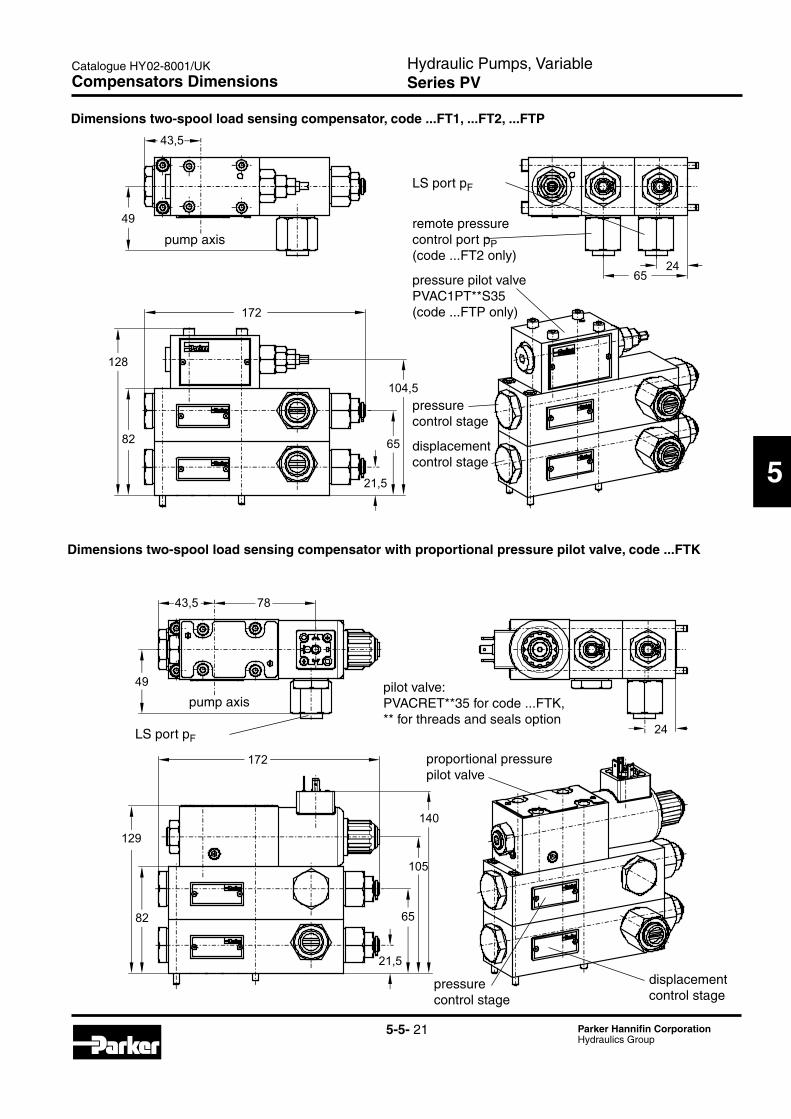
128
21,5
65
104,5
43,5
2465
172
49
43,5 78
49
82
129
21,5
65
105
140
172
24
pump axis
LS port pF
Dimensions two-spool load sensing compensator, code ...FT1, ...FT2, ...FTP
Dimensions two-spool load sensing compensator with proportional pressure pilot valve, code ...FTK
displacement control stage
pressure control stage
pump axis
LS port pF
displacement control stage
pressure control stage
proportional pressure pilot valve
pressure pilot valve PVAC1PT**S35 (code ...FTP only)
pilot valve: PVACRET**35 for code ...FTK,** for threads and seals option
remote pressure control port pP (code ...FT2 only)
Hydraulic Pumps, VariableSeries PV
Catalogue HY02-8001/UK
5-5- 22 Parker Hannifin CorporationHydraulics Group
11194,5
91
133
222
95
107
71
24
48
Compensators Dimensions
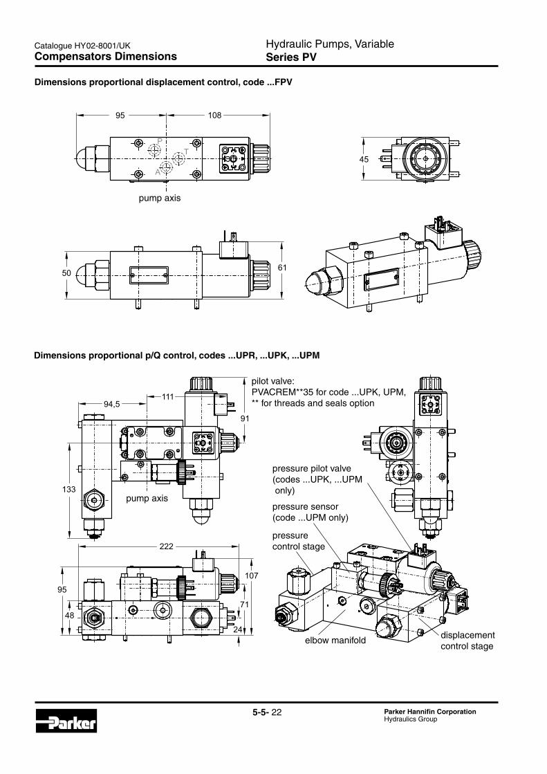
Dimensions proportional p/Q control, codes ...UPR, ...UPK, ...UPM
Dimensions proportional displacement control, code ...FPV
pump axis
pump axis
displacement control stage
pressure control stage
elbow manifold
pressure pilot valve (codes ...UPK, ...UPM only)
pressure sensor (code ...UPM only)
pilot valve: PVACREM**35 for code ...UPK, UPM,** for threads and seals option
Hydraulic Pumps, VariableSeries PV
Catalogue HY02-8001/UK
5-5- 23 Parker Hannifin CorporationHydraulics Group
5
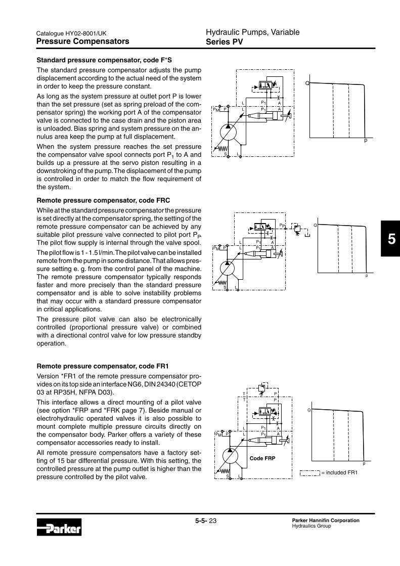
Standard pressure compensator, code F*SThe standard pressure compensator adjusts the pump displacement according to the actual need of the system in order to keep the pressure constant.
As long as the system pressure at outlet port P is lower than the set pressure (set as spring preload of the com-pensator spring) the working port A of the compensator valve is connected to the case drain and the piston area is unloaded. Bias spring and system pressure on the an-nulus area keep the pump at full displacement.
When the system pressure reaches the set pressure the compensator valve spool connects port P1 to A and builds up a pressure at the servo piston resulting in a downstroking of the pump. The displacement of the pump iscontrolled inorder tomatch theflowrequirementofthe system.
Remote pressure compensator, code FRCWhile at the standard pressure compensator the pressure is set directly at the compensator spring, the setting of the remote pressure compensator can be achieved by any suitable pilot pressure valve connected to pilot port PP. The pilot flow supply is internal through the valve spool.
The pilot flow is 1 - 1.5 l/min. The pilot valve can be installed remote from the pump in some distance. That allows pres-sure setting e. g. from the control panel of the machine. The remote pressure compensator typically responds faster and more precisely than the standard pressure compensator and is able to solve instability problems that may occur with a standard pressure compensator in critical applications.
The pressure pilot valve can also be electronically controlled (proportional pressure valve) or combined with a directional control valve for low pressure standby operation.
Remote pressure compensator, code FR1Version *FR1 of the remote pressure compensator pro-vides on its top side an interface NG6, DIN 24340 (CETOP 03 at RP35H, NFPA D03).
This interface allows a direct mounting of a pilot valve (see option *FRP and *FRK page 7). Beside manual or electrohydraulic operated valves it is also possible to mount complete multiple pressure circuits directly on the compensator body. Parker offers a variety of these compensator accessories ready to install.
All remote pressure compensators have a factory set-ting of 15 bar differential pressure. With this setting, the controlled pressure at the pump outlet is higher than the pressure controlled by the pilot valve.
Pressure Compensators
Code FRP
= included FR1
Hydraulic Pumps, VariableSeries PV
Catalogue HY02-8001/UK
5-5- 24 Parker Hannifin CorporationHydraulics Group
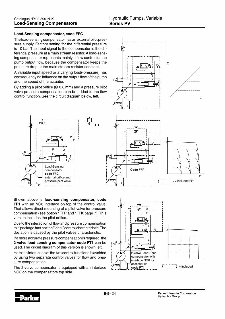
Load-Sensing compensator code FFCexternal orifice and pressure pilot valve
Load-Sensing compensator, code FFCThe load-sensing compensator has an external pilot pres-sure supply. Factory setting for the differential pressure is 10 bar. The input signal to the compensator is the dif-ferential pressure at a main stream resistor. A load-sens-ing compensator represents mainly a flow control for the pump output flow, because the compensator keeps the pressure drop at the main stream resistor constant.
A variable input speed or a varying load(-pressure) has consequentlynoinfluenceontheoutputflowofthepumpand the speed of the actuator.
By adding a pilot orifice (Ø 0.8 mm) and a pressure pilot valve pressure compensation can be added to the flow control function. See the circuit diagram below, left.
Load-Sensing Compensators
Code FFP
= included FF1
Q
Shown above is load-sensing compensator, code FF1 with an NG6 interface on top of the control valve. That allows direct mounting of a pilot valve for pressure compensation (see option *FFP and *FFK page 7). This version includes the pilot orifice.
Due to the interaction of flow and pressure compensation this package has not the ”ideal” control characteristic. The deviation is caused by the pilot valves characteristic.
Ifamoreaccuratepressurecompensationisrequired,the2-valve load-sensing compensator code FT1 can be used. The circuit diagram of this version is shown left.
Here the interaction of the two control functions is avoided by using two separate control valves for flow and pres-sure compensation.
The2-valvecompensatorisequippedwithaninterfaceNG6 on the compensators top side.
= included
p
Q
T P
P L
S L
AP1PM
L
T
A
P
P1
PF
2-valve Load-Sens. compensator with interface NG6 for accessoriescode FT1
Hydraulic Pumps, VariableSeries PV
Catalogue HY02-8001/UK
5-5- 25 Parker Hannifin CorporationHydraulics Group
5
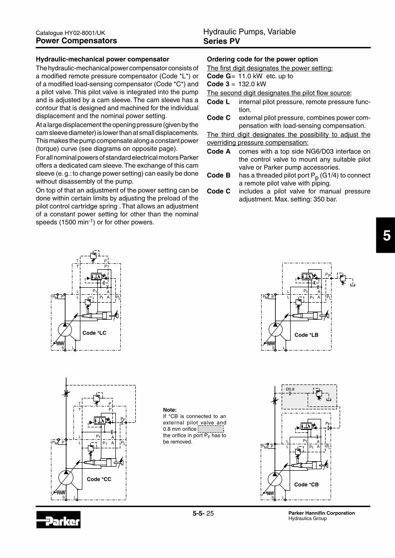
Hydraulic-mechanical power compensatorThe hydraulic-mechanical power compensator consists of a modified remote pressure compensator (Code *L*) or of a modified load-sensing compensator (Code *C*) and a pilot valve. This pilot valve is integrated into the pump and is adjusted by a cam sleeve. The cam sleeve has a contour that is designed and machined for the individual displacement and the nominal power setting.At a large displacement the opening pressure (given by the cam sleeve diameter) is lower than at small displacements. This makes the pump compensate along a constant power (torque)curve(seediagramsonoppositepage).For all nominal powers of standard electrical motors Parker offers a dedicated cam sleeve. The exchange of this cam sleeve (e. g.: to change power setting) can easily be done without disassembly of the pump.On top of that an adjustment of the power setting can be done within certain limits by adjusting the preload of the pilot control cartridge spring . That allows an adjustment of a constant power setting for other than the nominal speeds (1500 min-1) or for other powers.
Ordering code for the power optionThe first digit designates the power setting:Code G = 11.0 kW etc. up toCode 3 = 132.0 kW The second digit designates the pilot flow source:Code L internal pilot pressure, remote pressure func-
tion.Code C external pilot pressure, combines power com-
pensation with load-sensing compensation.The third digit designates the possibility to adjust the overriding pressure compensation:Code A comes with a top side NG6/D03 interface on
the control valve to mount any suitable pilot valve or Parker pump accessories.
Code B has a threaded pilot port Pp (G1/4) to connect a remote pilot valve with piping.
Code C includes a pilot valve for manual pressure adjustment. Max. setting: 350 bar.
Power Compensators
PP
PP P P P
AA
P P PP
P
P
PP
P
PP
PP
PP
P
P P
PP
P
AA
AA
AA
Ø0,8
Code *LC Code *LB
Code *CBCode *CC
Note:If *CB is connected to an external pilot valve and 0.8 mm orifice , the orifice in port PF has to be removed.
Hydraulic Pumps, VariableSeries PV
Catalogue HY02-8001/UK
5-5- 26 Parker Hannifin CorporationHydraulics Group
200210
180
160
140
120
100
80
60
40
20
00 50 100 150 200 250 300 350
PV14055 kW
37 kW30 kW22 kW18,5 kW
75 kW
45 kW
90kW
300
270
240
210
180
150
120
90
60
30
00 50 100 150 200 250 300 350
PV180
55 kW45 kW37 kW22 kW
30 kW
75 kW
110 kW90kW
140
120
100
80
60
40
20
00 50 100 150 200 250 300 350
PV092PV080PV063
30 kW22 kW
18,5 kW11 kW
15 kW
37 kW
55 kW45kW
300
350
425
250
200
150
100
50
00 50 100 150 200 250 300 350
PV270
55 kW45 kW37 kW
132 kW
75 kW
110 kW90kW
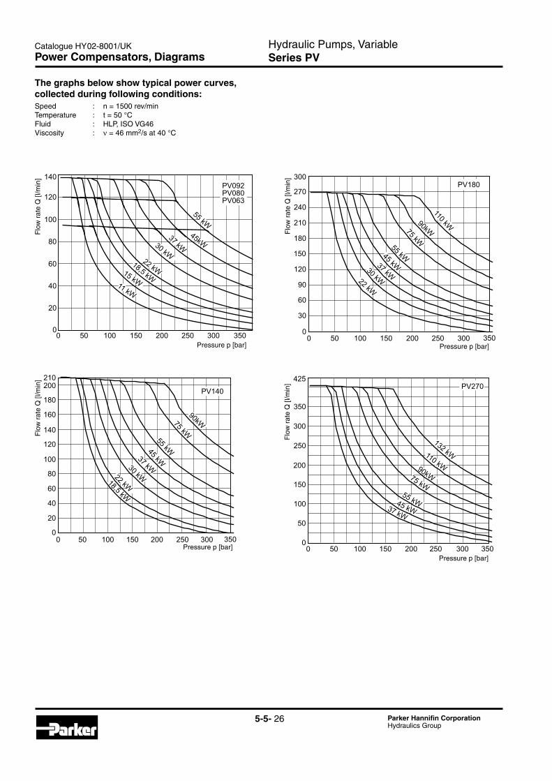
Power Compensators, Diagrams
The graphs below show typical power curves, collected during following conditions:Speed : n = 1500 rev/minTemperature : t = 50 °CFluid : HLP, ISO VG46Viscosity : ν = 46 mm2/s at 40 °C
Flo
w r
ate
Q [l
/min
]F
low
rat
e Q
[l/m
in]
Flo
w r
ate
Q [l
/min
]F
low
rat
e Q
[l/m
in]
Pressure p [bar]
Pressure p [bar] Pressure p [bar]
Pressure p [bar]
Hydraulic Pumps, VariableSeries PV
Catalogue HY02-8001/UK
5-5- 27 Parker Hannifin CorporationHydraulics Group
5
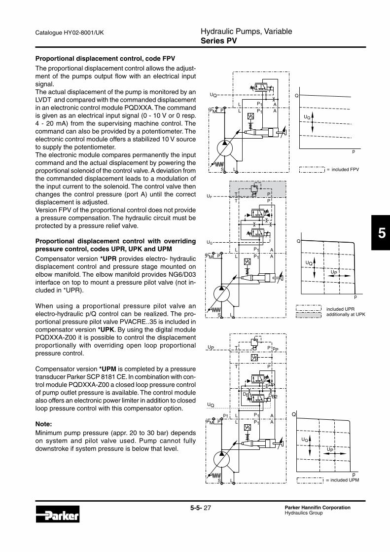
Proportional displacement control, code FPVThe proportional displacement control allows the adjust-ment of the pumps output flow with an electrical input signal.The actual displacement of the pump is monitored by an LVDT and compared with the commanded displacement in an electronic control module PQDXXA. The command is given as an electrical input signal (0 - 10 V or 0 resp. 4 - 20 mA) from the supervising machine control. The command can also be provided by a potentiometer. The electronic control module offers a stabilized 10 V source to supply the potentiometer.The electronic module compares permanently the input command and the actual displacement by powering the proportional solenoid of the control valve. A deviation from the commanded displacement leads to a modulation of the input current to the solenoid. The control valve then changes the control pressure (port A) until the correct displacement is adjusted.Version FPV of the proportional control does not provide a pressure compensation. The hydraulic circuit must be protected by a pressure relief valve.
Proportional displacement control with overriding pressure control, codes UPR, UPK and UPMCompensator version *UPR provides electro- hydraulic displacement control and pressure stage mounted on elbow manifold. The elbow manifold provides NG6/D03 interface on top to mount a pressure pilot valve (not in-cluded in *UPR).
When using a proportional pressure pilot valve an electro-hydraulic p/Q control can be realized. The pro-portional pressure pilot valve PVACRE..35 is included in compensator version *UPK. By using the digital module PQDXXA-Z00 it is possible to control the displacement proportionally with overriding open loop proportional pressure control.
Compensator version *UPM is completed by a pressure transducer Parker SCP 8181 CE. In combination with con-trol module PQDXXA-Z00 a closed loop pressure control of pump outlet pressure is available. The control module also offers an electronic power limiter in addition to closed loop pressure control with this compensator option.
Note:Minimum pump pressure (appr. 20 to 30 bar) depends on system and pilot valve used. Pump cannot fully downstroke if system pressure is below that level.
p
Q
UP
UQ
T P
P L
S L
AP1PMsU
L
T
A
P
P1
UP
UQ
P L
S L
AP1PMs
p
U
U
L
T
A
P
P1
T P
DB1 DB2
DP
p1
pP
UP
UQ
UP
UQ
Q
p= included
P L
S L
AP1PMsU
L AP1
UQ
p
Q
UQ
= includedincluded FPV
included UPRadditionally at UPK
included UPM
Hydraulic Pumps, VariableSeries PV
Catalogue HY02-8001/UK
5-5- 28 Parker Hannifin CorporationHydraulics Group
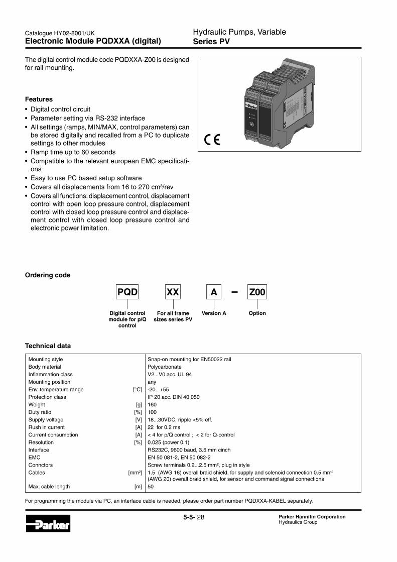
Electronic Module PQDXXA (digital)
The digital control module code PQDXXA-Z00 is designed for rail mounting.
Ordering code
OptionFor all frame sizes series PV
Digital control module for p/Q
control
Version A
Features• Digitalcontrolcircuit• ParametersettingviaRS-232interface• Allsettings(ramps,MIN/MAX,controlparameters)can
be stored digitally and recalled from a PC to duplicate settings to other modules
• Ramptimeupto60seconds• CompatibletotherelevanteuropeanEMCspecificati-
ons• EasytousePCbasedsetupsoftware• Coversalldisplacementsfrom16to270cm³/rev• Coversallfunctions:displacementcontrol,displacement
control with open loop pressure control, displacement control with closed loop pressure control and displace-ment control with closed loop pressure control and electronic power limitation.
Technical data
Mounting style Snap-on mounting for EN50022 railBody material PolycarbonateInflammation class V2...V0 acc. UL 94Mounting position anyEnv. temperature range [°C] -20...+55Protection class IP 20 acc. DIN 40 050Weight [g] 160Dutyratio [%] 100Supplyvoltage [V] 18...30VDC,ripple<5%eff.Rush in current [A] 22 for 0.2 msCurrentconsumption [A] <4forp/Qcontrol;<2forQ-controlResolution [%] 0.025(power0.1)Interface RS232C, 9600 baud, 3.5 mm cinchEMC EN 50 081-2, EN 50 082-2Connctors Screw terminals 0.2...2.5 mm², plug in styleCables [mm²] 1.5 (AWG 16) overall braid shield, for supply and solenoid connection 0.5 mm² (AWG 20) overall braid shield, for sensor and command signal connectionsMax. cable length [m] 50
PQD XX A
For programming the module via PC, an interface cable is needed, please order part number PQDXXA-KABEL separately.
Z00
Hydraulic Pumps, VariableSeries PV
Catalogue HY02-8001/UK
5-5- 29 Parker Hannifin CorporationHydraulics Group
5
General Installation Information
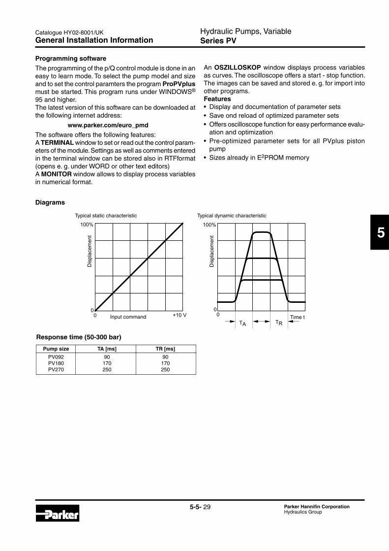
Programming softwareThe programming of the p/Q control module is done in an easy to learn mode. To select the pump model and size and to set the control paramters the program ProPVplus must be started. This program runs under WINDOWS® 95 and higher.The latest version of this software can be downloaded at the following internet address:
www.parker.com/euro_pmd
The software offers the following features:A TERMINAL window to set or read out the control param-eters of the module. Settings as well as comments entered in the terminal window can be stored also in RTFformat (opens e. g. under WORD or other text editors)A MONITOR window allows to display process variables in numerical format.
Diagrams
100% 100%
00
00
+10 VTA TR
An OSZILLOSKOP window displays process variables as curves. The oscilloscope offers a start - stop function. The images can be saved and stored e. g. for import into other programs.Features• Displayanddocumentationofparametersets• Saveondreloadofoptimizedparametersets• Offersoscilloscopefunctionforeasyperformanceevalu-
ation and optimization• Pre-optimized parameter sets for all PVplus piston
pump• SizesalreadyinE2PROM memory
Response time (50-300 bar)
Pump size TA [ms] TR [ms]
PV092 90 90 PV180 170 170 PV270 250 250
Typical static characteristic Typical dynamic characteristic
Dis
plac
emen
t
Dis
plac
emen
t
Input command Time t
Hydraulic Pumps, VariableSeries PV
Catalogue HY02-8001/UK
5-5- 30 Parker Hannifin CorporationHydraulics Group
Accessories Compensator
Code Seals
N NBR V FPM
ACPV
Function SolenoidFor PV pump
series
AdjustmentSealsAccessories for
compensa-tors
Solenoid acces-sories
Mounting bolts
Nominal pressure350 bar
35
Code Function
1P Max. pressure relief
1E 1 pressure, electrical unloading
2P 2 pressures, electrical selection
2 pressures + stands 2E electrical selection low pressure default
2 pressures + stands 2M electrical selection stand by default
Code Mounting bolts
C For single compensators type R or F S Without bolts M For code UP*/MT* + DS 45 U For code UP* + DS 42
Code Solenoid accessories
omit For function 1P
C Conduit box with free wires
W DIN plug socket without plug
Code Solenoid voltage
omit For function 1P
Y 110V/50Hz - 120V/60Hz
T 220V/50Hz - 240V/60Hz
J 24V DC
Code Adjustment
S Spindle with lock nut
PVAC2P* PVAC2M*/PVAC2E*
PVAC1E*PVAC1P*
48
133
48
133
48
133
Dimensions
Code Threads
M Metric S SAE / UNC
Threads
Compensator accessory only available on pump, not as single items (replacement kit see spare part list PVI-PVAC-UK).
AdjustmentCode S
Highpressure
Highpressure
Lowpressure
Lowpressure
DC solenoid 205AC solenoid 190
DC solenoid 205AC solenoid 190
DC solenoid 241AC solenoid 211
Hydraulic Pumps, VariableSeries PV
Catalogue HY02-8001/UK
5-5- 31 Parker Hannifin CorporationHydraulics Group
5
Accessories Compensator
Schematics PVAC1P* Schematics PVAC1E*
Schematics PVAC2P* Schematics PVAC2M*/PVAC2E*
*2M*
Hydraulic Pumps, VariableSeries PV
Catalogue HY02-8001/UK
5-5- 32 Parker Hannifin CorporationHydraulics Group
Accessories Compensator
Ordering code proportional pressure control valve
Schematic PVACRE* Dimensions PVACRE*
Proportional pressure control valveProportional pressure pilot valves of series PVACRE* (RE06...) are powered by external electronic modules
(see catalogue HY11-3500 for reference). They allow an infinite electronic adjustment of the pumps compensat-ing pressure.
Code Seal
N NBR V FPM
ACPV
Prop. pressure
valve
Pumpseries PV
SealAccessories for controller
RE
Code Nominal pressure
35 350 bar 42 420 bar
Nominal pressure
Mounting bolts
Thread option
Code Thread option
M Metric S SAE / UNC
Code Mounting bolts/ ports
C For single controller type *MR* or *MF*
T For double valve contr. type *FT*
S Without bolts
M For code UP*/MT* + DS 45
U For code UP* + DS 42
Example for PVACRE* mounted