optimization of 16” plug valve body using fea and
TRANSCRIPT

International Journal of Mechanical Engineering
ISSN : 2277-7059 Volume 1 Issue 1 http://www.ijmejournal.com/ https://sites.google.com/site/journalijme/
79
Optimization of 16” Plug Valve Body Using FEA
And Experimental Stress Analysis Method
Deokar Vinayak Hindurao1, D.S.Chavan
2
Rajarambapu Institute Of technology, Sakharale, Tal-Walwa, Dist- Sangali, Maharashtra, India, [email protected]
Abstract. In the field of competition, all companies should supply their goods and services with high quality, in shortest period with lower prices than its competitors in order to keep their capacity and power to compete .Plug valves are machine elements
which are commonly used for regulation of fluid, semi-liquid and granular medium flow on variety of tanks and pipeline systems.
This paper discusses FEA analysis of P lug–valve body followed by Experimental stress analysis using strain gauge method for weight optimization. New optimized models were prepared on the basis of validation of the results obtained from stress analys is procedure. The weight reduction is done by changing the wall and rib thickness. The results clearly shows the maximum weight
reduction is 24.86 kg (5.26%) weight of original weight while keeping maximum stress level up to 168.6 N/mm2
which is safe for the applied load.
1. Introduction
Fig 1.1plug valve
A plug valve is a quarter-turn rotational motion valve that uses a tapered or cylindrical plug to stop or start flow. The plug valves have one or more hollow passageways going sideways through plug; so that fluid can flow through plug when the valve is
opened Material used for casting of valve body is Carbon steel. These valves are mainly used in petrochemical industries the purpose of every valve used is to control the flow of volatile, often toxic, liquids and gases and keep them from being emitted into the atmosphere or spilled on the ground or into the water.
2 Finite Element Analysis
2.1 3D Modeling and meshing
In ANSYS it’s very difficult to model the part with parametric modeling as compared with the available modeling software such as CATIA and Pro-E. The created 3D model of valve body is as shown in fig2.1. Meshing is carried out by using Hypermesh software as
shown in fig 2.2. Model is meshed by using SOLID 45 element and with 10 element size.

International Journal of Mechanical Engineering
ISSN : 2277-7059 Volume 1 Issue 1 http://www.ijmejournal.com/ https://sites.google.com/site/journalijme/
80
Fig 2.1 - 3D Model Fig 2.2 - Meshed valve body model
2.2 Loads and boundary conditions
Structural loading means applying internal hydraulic pressure to valve body. Internal pressures 7.58 MPa were applied on the
all inner surface of a valve body, which is shown by red colored arrows in the fig. All degree of freedoms of inlet and outlet flanges is
restricted and it is shown with the help of green color in the figure 2.3.
Fig 2.3 - Loads and boundary conditions Applied
2.3 Results and their physical interpretation
Results of FEA for 7.58 MPa internal pressure condition are shown in following figures.
Figure 2.4 - Von-mises stress plot Figure 2.5 - 1st principal stress
International Journal of Mechanical Engineering
ISSN : 2277-7059 Volume 1 Issue 1 http://www.ijmejournal.com/ https://sites.google.com/site/journalijme/
81
From above obtained results it is clear that the maximum principal stress 156.75 N/mm2
founds in the rib at 7.58 MPa internal
pressures. While minimum principal stress (2nd
principal stress) 29.53 N/mm2 found at flange corner for 7.58 MPa internal pressures.
As the internal pressure acts on the internal effective pressurizing area of valve body, results to expand the valve body .Ribs tries to hold the valve body in original position so ribs subjects to heavy tensile stress. As the internal pressure increases stresses in the valve body increases linearly.
3 Experimental Stress analysis
3.1 Experimental setup
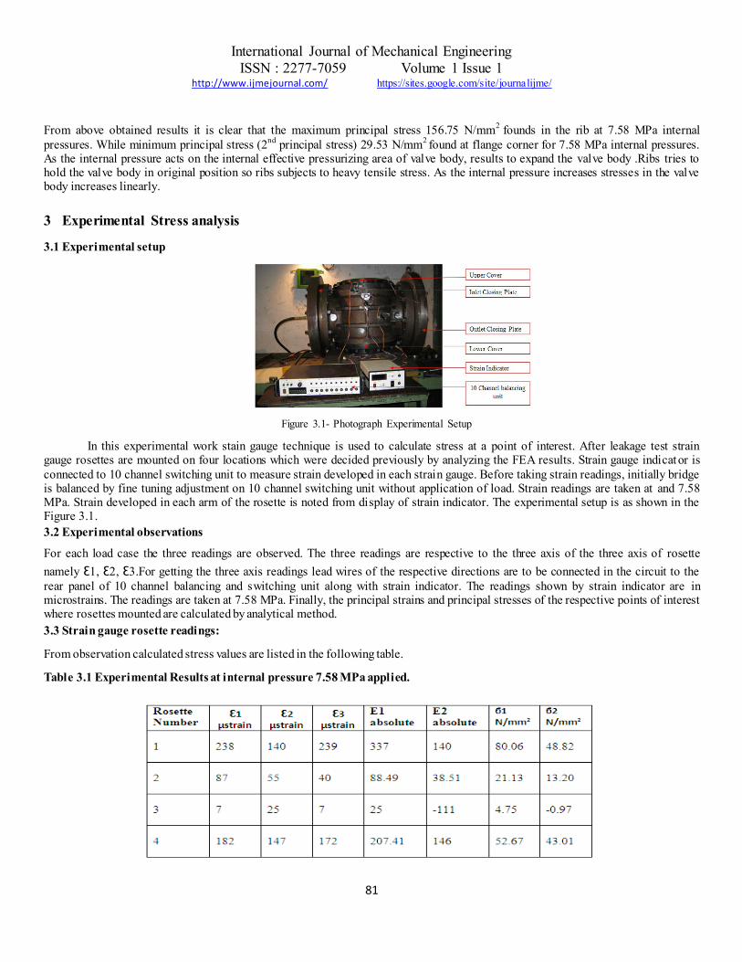
Figure 3.1- Photograph Experimental Setup
In this experimental work stain gauge technique is used to calculate stress at a point of interest. After leakage test strain gauge rosettes are mounted on four locations which were decided previously by analyzing the FEA results. Strain gauge indicator is
connected to 10 channel switching unit to measure strain developed in each strain gauge. Before taking strain readings, initially bridge is balanced by fine tuning adjustment on 10 channel switching unit without application of load. Strain readings are taken at and 7.58 MPa. Strain developed in each arm of the rosette is noted from display of strain indicator. The experimental setup is as shown in the Figure 3.1.
3.2 Experimental observations
For each load case the three readings are observed. The three readings are respective to the three axis of the three axis of rosette
namely Ɛ1, Ɛ2, Ɛ3.For getting the three axis readings lead wires of the respective directions are to be connected in the circuit to the
rear panel of 10 channel balancing and switching unit along with strain indicator. The readings shown by strain indicator are in microstrains. The readings are taken at 7.58 MPa. Finally, the principal strains and principal stresses of the respective points of interest where rosettes mounted are calculated by analytical method.
3.3 Strain gauge rosette readings:
From observation calculated stress values are listed in the following table.
Table 3.1 Experimental Results at internal pressure 7.58 MPa applied.
International Journal of Mechanical Engineering
ISSN : 2277-7059 Volume 1 Issue 1 http://www.ijmejournal.com/ https://sites.google.com/site/journalijme/
82
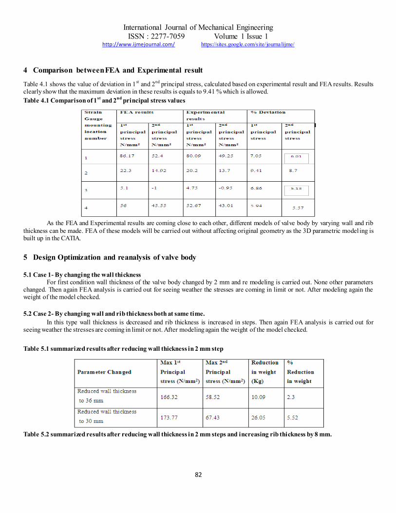
4 Comparison between FEA and Experimental result
Table 4.1 shows the value of deviation in 1st and 2
nd principal stress, calculated based on experimental result and FEA results. Results
clearly show that the maximum deviation in these results is equals to 9.41 % which is allowed.
Table 4.1 Comparison of 1st
and 2nd
principal stress values
As the FEA and Experimental results are coming close to each other, different models of valve body by varying wall and rib
thickness can be made. FEA of these models will be carried out without affecting original geometry as the 3D parametric model ing is built up in the CATIA.
5 Design Optimization and reanalysis of valve body
5.1 Case 1- By changing the wall thickness
For first condition wall thickness of the valve body changed by 2 mm and re modeling is carried out. None other parameters changed. Then again FEA analysis is carried out for seeing weather the stresses are coming in limit or not. After modeling again the weight of the model checked.
5.2 Case 2- By changing wall and rib thickness both at same time.
In this type wall thickness is decreased and rib thickness is increased in steps. Then again FEA analysis is carried out for seeing weather the stresses are coming in limit or not. After modeling again the weight of the model checked.
Table 5.1 summarized results after reducing wall thickness in 2 mm step
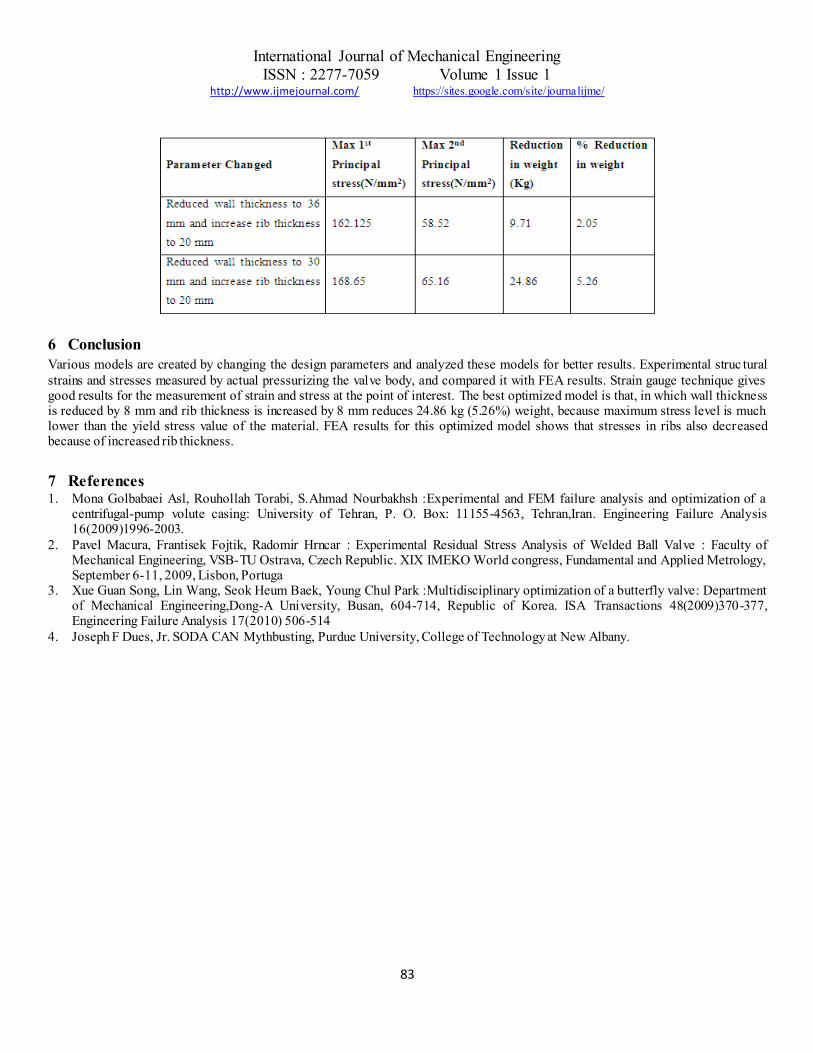
Table 5.2 summarized results after reducing wall thickness in 2 mm steps and increasing rib thickness by 8 mm.
International Journal of Mechanical Engineering
ISSN : 2277-7059 Volume 1 Issue 1 http://www.ijmejournal.com/ https://sites.google.com/site/journalijme/
83
6 Conclusion
Various models are created by changing the design parameters and analyzed these models for better results. Experimental struc tural
strains and stresses measured by actual pressurizing the valve body, and compared it with FEA results. Strain gauge technique gives good results for the measurement of strain and stress at the point of interest. The best optimized model is that, in which wall thickness is reduced by 8 mm and rib thickness is increased by 8 mm reduces 24.86 kg (5.26%) weight, because maximum stress level is much lower than the yield stress value of the material. FEA results for this optimized model shows that stresses in ribs also decreased because of increased rib thickness.
7 References 1. Mona Golbabaei Asl, Rouhollah Torabi, S.Ahmad Nourbakhsh :Experimental and FEM failure analysis and optimization of a
centrifugal-pump volute casing: University of Tehran, P. O. Box: 11155-4563, Tehran,Iran. Engineering Failure Analysis 16(2009)1996-2003.
2. Pavel Macura, Frantisek Fojtik, Radomir Hrncar : Experimental Residual Stress Analysis of Welded Ball Valve : Faculty of Mechanical Engineering, VSB-TU Ostrava, Czech Republic. XIX IMEKO World congress, Fundamental and Applied Metrology, September 6-11, 2009, Lisbon, Portuga
3. Xue Guan Song, Lin Wang, Seok Heum Baek, Young Chul Park :Multidisciplinary optimization of a butterfly valve: Department of Mechanical Engineering,Dong-A University, Busan, 604-714, Republic of Korea. ISA Transactions 48(2009)370-377, Engineering Failure Analysis 17(2010) 506-514
4. Joseph F Dues, Jr. SODA CAN Mythbusting, Purdue University, College of Technology at New Albany.