lt valve manual - allendorph...
TRANSCRIPT

Revision A Date: 8/7/2007
LT Valve Technical Manual
Phoinix Global 903 Commerce Rd Alice, Texas 78332 Phone: 361.664.6163 Fax: 361.664.6265

Revision A Date: 8/7/2007
Table of Contents
1.0 Overview
2.0 Parts List
3.0 Assembly Procedure
4.0 Disassembly/Repair Procedure
5.0 Maintenance
6.0 Storage

Revision A Date: 8/7/2007
1.0 Overview
The Phoinix Global LT plug valve is a tapered pocket, quarter turn plug valve. All components are manufactured to API 6A specifications and engineered to provide excellent service over the life of the product.
Various sizes are available from 1” to 4” in hammer union and in flanged configurations.
Consult Phoinix Global Product Manual for a complete listing of currently supplied valves.

Revision A Date: 8/7/2007
ITEM NO. PART NO. DESCRIPTION QTY.
1 VB2L-2CFM-S01 VLV BODY-LT, 2"x2"1502FM STD 15K 1 2 VP2L-S01 VALVE PLUG, 2"LT STD 1 3 VAN2L-H01 VALVE ADJUSTING NUT, 2" H2S 1 4 VIN2L VALVE INSERT,2"LT STD 1 5 VOR2L-A-S01 VALVE O-RING, 2" STD BUNA 90 (ADJ NUT) 1 6 VOR2L-I-S01 VALVE O-RING, 2" STD BUNA 90 (INSERT) 2 7 F-WFF-0.500 WASHER, FLAT FENDER 1/2" 2 8 F-WFS-0.500 WASHER, FLAT STD 1/2" 2 9 F-HHC0.50-20X1.00-G8 CAP SCREW, HEX HD 1/2"-20 x 01.00"LONG 2
10 VPS2L-S01 VALVE PLUG SEAL, 2" & 3" STD BRASS/BUNA 90 2 11 VH2L VALVE HANDLE 2" 1 12 F-SS0.375X0.75-D SET SCREW, SOCKET HD 3/8"-16 x 0.75"LONG DOGPOINT 2 13 F-SHC0.50-13X0.50-G5 CAP SCREW, SOC HD 1/2"-13 x 00.50"LONG 1 14 GF001 GREASE FITTING, 3/4"-10 GIANT BUTTON HEAD H2S 1 15 UNRC2 NUT RETAINER, 2"1502 1 16 UWN-2C-D-S WINGNUT, 2"1502 STD 15K DETACHABLE 1 17 URRC2 RETAINER RING, 2"1502 1 18 USR2-S01 SEAL RING, 2"602/1002/1502 STD BUNA 90 1
2.0 Parts List
All valves have generally the same parts in different sizes. Phoinix Global uses the following names for valve components designated by size. The following image is a 2” 1502 valve with part numbers and names.

Revision A Date: 8/7/2007
Phoinix Global 2” 1502 Exploded View

Revision A Date: 8/7/2007
3.0 Assembly Procedure
NOTE: It is imperative that the workstation being used to assemble the valve be clean and free of anything that could possibly contami-nate the grease such as metal shavings, dirt, rust, old paint, etc. Do not sand or deburr near the workstation.
Step 1: Check surfaces around the valve bore inside the valve pocket for sharp edges that could cause cutting of the insert o-rings.
step 2: Screw the clean adjusting nut (3) all the way into the valve body to make sure the threads are not damaged. After inspection, remove the adjusting nut (3) and install adjusting nut o-ring (5).

Revision A Date: 8/7/2007
step 3: Check the roll pins (not shown) in the valve body by gently sliding a set of inserts (4) into the valve. The inserts should move freely up and down the length of the roll pin slots
step 4: Install the plug seals (10) into the recess in the valve body and adjusting nut with the metal back up to-wards the recess and facing away from the pressure. Al-ways apply a film of lubricant before pressing the plug seals into place.
step 5: Check the plug (2) outside diameter for surface defects such as nicks, dings, scratches, etc. that could pos-sibly affect the sealing area.

Revision A Date: 8/7/2007
Step 7: Pack adjusting nut (3) plug seal (10) with valve grease.
step 8: Apply a thin film of grease to the entire O.D. of
step 6: Check the surface finish of the inserts (4) making sure it does not have any scratches, dings, nicks, or sharp edges that could also affect the sealing area. Inspect the o-rings for any possible defects.

Revision A Date: 8/7/2007
Step 9: 1” valves, insert the plug into the recess of the ad-justing-nut (3) but do not push the plug (2) all the way down. Place the inserts (4) around the plug (2) and align the plug bore with the insert bore. Push the plug (2) down until it shoulders at the bottom of the recess on the inserts (4).
NOTE: Install the lower end of the plug (2) (opposite the hex) in the adjusting nut (3) and push down until the plug shoulders on the adjusting nut. For 2 and 3 inch valves, the plug rests on the adjusting nut with the inserts sliding into grooves on the adjusting nut. The 1 and 4 inch valves, the plug rests on the inserts.

Revision A Date: 8/7/2007
Step 10: Place the inserts (4) around the plug and insert the o-rings into the grooves and pack with grease to thoroughly grease the sealing surface.

Revision A Date: 8/7/2007
step 11: Secure the plug to the adjusting nut with a cap screw (9) and two washers (7 & 8).
step 12: Lubricate the valve pocket.
step 13: Apply thread compound to the adjusting threads and adjusting nut sealing surfaces.
Revision A Date: 8/7/2007
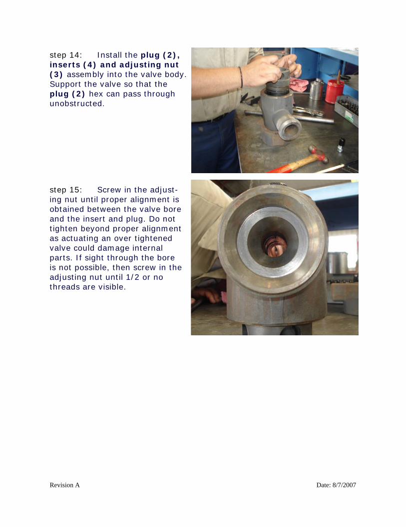
step 14: Install the plug (2), inserts (4) and adjusting nut (3) assembly into the valve body. Support the valve so that the plug (2) hex can pass through unobstructed.
step 15: Screw in the adjust-ing nut until proper alignment is obtained between the valve bore and the insert and plug. Do not tighten beyond proper alignment as actuating an over tightened valve could damage internal parts. If sight through the bore is not possible, then screw in the adjusting nut until 1/2 or no threads are visible.

Revision A Date: 8/7/2007
step 16: Install grease fitting (14). Always lubricate all threads prior to installation.
step 17: Install cap screw (13) and valve handle (11) on top of the valve and secure with a cap screw (9) and two washers (7 & 8).
step 18: Remove excess grease from valve bore and inspect plug alignment. Adjust as necessary with adjusting nut (3) to align vertically. Align plug in open po-sition and adjust set screw (12) to achieve proper stop. Close valve and adjust other set screw (12) so that plug is approxi-mately 90o from open position. Adjusting the set screws for proper “open and close” positions will prevent premature wear.

Revision A Date: 8/7/2007
step 19 Open the valve with the handle adapter (11) and pump grease through the grease fitting (14) to approximately 3000 p.s.i. Actuate the valve to release grease pressure.

Revision A Date: 8/7/2007
4.0 Disassembly/Repair Procedure
A valve is typically disassembled to install a repair kit or to simply clean and inspect the valve. To install a repair kit or disassembly a valve: 1. Remove cap screw (9) and washers (7 & 8) from top of valve.
Set hardware and valve handle (11) aside.
2. Back adjusting nut (3) out to remove internals from valve body.
3. Remove all seals from valve body (1).
4. Clean valve pocket to ensure that it is free from grime and grit.
5. Clean adjusting nut (3).
6. Inspect all sealing surfaces for dings and scratches in the valve body (1) and plug seal locations and adjusting nut seal area. This should be done on the new plug (2) and insert (4) as well to verify that the parts haven’t been damaged in transit.
7. All scratches and dings should be lightly sanded with 600 grit sand
paper. Verify that adjusting nut (3) doesn’t have any dings or sharp edges that could cut the o-ring (5). Lightly polish with sand paper as necessary.
8. Inspect threads on adjusting nut (3) and valve body (1). Any
minor dings should be removed with sand paper.
9. Install repair kit or re-install parts using the assembly procedure.

Revision A Date: 8/7/2007
5.0 Maintenance
A strict policy of greasing a valve is required to ensure proper opera-tion. Lack grease in valves is the single largest cause of:
• Leaking valves • Hard actuation • Scarred internals • Corroded surfaces
Phoinix Global recommends that valves be greased every 5 actuations or every job, whichever comes first. Additionally, specific applications may require more greasing based on actual experience with the products in actual operating environments. For instance, abrasive flow streams, high temperatures, high flow rates, corrosive flow streams, and fluid streams that act as solvents will warrant a more frequent greasing regimen than operations where these conditions are not present.

Revision A Date: 8/7/2007
6.0 Storage
Recommended shelf life storage:
• 0 to 3 months – nothing required • 3 to 6 months – re-grease and operate by rotating plug. Make
sure operation is smooth and free of grinding or scraping. • 6 or more months – Disassemble, clean, and rebuild and test.
Replace all seals.
After use: Equipment should be disassembled and cleaned after each use to en-sure a long life. Corrosive products left in a valve will greatly reduce the life of the valve.