optimal design 5 report design 5 report lift system to ascend/descend stairs team #5 leah mcelhaney...
TRANSCRIPT

Optimal Design 5 Report
Lift System to Ascend/Descend Stairs
Team #5
Leah McElhaney
Jordan R. Smith
Kayla Gosse
Project for Client: Danielle Giroux
Client Contact Information:
Dave and Suzanne Giroux
53 Charlotte Dr, Tolland, CT 06084
860-604-0893
1. Optimal Design Project 5
1.1. Introduction
The automatic lift to ascend and descend front steps will be functional and practical
for the Giroux family. There are several critical components to the automatic lift that will be
taken into careful consideration. The client requests that the lift be transportable so that it can
be used in several locations. The lift will also be collapsible and able to fit into the family
van. When collapsed, the lift will not exceed a width of 18” to ensure enough room for the
client and her family members inside the van without jeopardizing safety. It is necessary that
the lift also have tie downs at the base for the client’s wheelchair. The tie-downs will secure
the client and her wheelchair to the lift surface so that there is no possibility of the client
slipping or sliding off the lift. Moreover, the client’s parents requested that the lift only be
functional with parental supervision. The lift will not be accessible to the client herself, and
will only be able to start and stop with assistance from a second party. The lift will be built to
suit the client’s manual wheelchair, as opposed to the client’s electric wheelchair. The
manual wheelchair is lightweight and portable, weighing approximately 30 pounds. The
client weighs approximately 75 pounds so the ramp will be designed to withstand
approximately 105 pounds. The ramp will also be designed to hold more weight to ensure
that as the client grows she can continue to use the lift.
The lift will consist of a manual scissor lift device with a ramp attached to it. The
scissor lift will be manual and portable. The lift capacity is 300 lbs which is suitable for the
client. The lift can reach heights from 10” to 33” which is ideal for a variety of stairs. The lift
is manually operated using a foot pump which can be easily activated by one of the client’s
parents. The scissor lift will also have an adjustable speed lowering via hand release from the
foot peddle. The scissor lift legs will be made of ½” aluminum plates. Aluminum will be
used instead of steel because it is lighter weight for easy transport. The scissor lift also
incorporates two fixed and two swivel casters for maneuverability. The platform of the
scissor lift will be 20”x32”. The platform will be equipped with tie downs for the client’s
wheelchair for safety. The scissor lift will also have a foot operated floor lock to position the
lift in place. To raise the lift, turn the release knob clockwise until it is fully closed. Press on
the foot pedal to raise the scissor lift. To lower the lift, slowly turn release knob counter-
clockwise until the desired rate of decent is achieved. To lock lift in position, press down on
the wheel breaks located on the swivel casters at the push handle end. Furthermore, the
scissor lift will require good quality oil with 150 SSU at 100°F. The oil must also have rust
and oxidation inhibitors and anti-wear properties. Oils to use are Exxon/Mobil DTE 24,
Exxon/Mobil NUTO H32, or Chevron Amaco AW32. It is very important to keep the
hydraulic oil free of dirt, rust, metal chips, water, and other contamination. This is because
most problems with hydraulic systems are caused by contamination in the oil. A schematic of
the lift parts and assembly is shown in Fig. 1.

Figure 1. Manual Scissor Lift Assembly
The manual scissor lift will successfully elevate the client to the desired height of the
stairs she wishes to ascend, but cannot transfer the client horizontally onto a porch or foyer.
This is why the lift system will also incorporate a ramp system that will be attached to the
lift. The ramp will be made of two aluminum pieces each approximately 4”. The two pieces
will be attached by a hinge system so that when the ramp is open, there is more support in the
center to hold the client’s weight. Additionally, there will be four support beams incorporated
into bottom of the ramp. The four support beams will be secured by latches and released
when the ramp is in use. The four support beams will fall on either side of the ramp and land
on the stairs beneath, adding more support for the client. The beams will also ensure that the
ramp will not buckle while in use. The four support beams will be made of two aluminum
rods each with 12 ½” holes drilled into them. The holes will be in 1” increments. This will
allow the support beams to be adjusted from a minimum of 6” to a maximum of 18” to
accommodate any size steps. The beams will be compact while tucked away under the ramp
exceeding no more than 20”. Each support beam will consist of two aluminum rods
approximately 12” long. One rod will fit inside the other and will be adjusted using the holes
described above. Additionally, there will be railings attached to the ramp system to ensure
the client’s safety while maneuvering across the ramp.
The final component to the lift system will be a threshold ramp located at the
threshold of the desired location. Since the ramp is not automated, once the client has been
elevated by the scissor ramp and maneuvered onto the porch over the ramp described above,
she will need to finally go over the threshold ramp to enter the building. The threshold ramp
will also be made of aluminum and will be adjustable. The maximum height for the threshold
ramp will be 6”. Once the client is safely in the desired location, the ramp can be folded up
and the lift can be lowered. The threshold ramp can be taken away manually and will not
weigh more than 20 lbs. The lift/ramp system will be able to be rolled and stored away until
the client is ready to exit the building.
This design was originally not part of the three alternative designs. The alternative
designs included a conveyor-belt type ramp, an electric lift system, and a manual ramp. The
electric lift system was the main inspiration for this final optimal design. However, this
design is not electric but manual because of the added benefits of using a manual lift as
opposed to an electric one. The manual lift will weigh less than an electric lift because it has
much fewer components. One main criterion for the lift system was that it be transportable. A
manual lift is much easier to transport than an electric lift.
1.2. Subunits
1.2.1. Manual Scissor Lift
The manual scissor lift will be made of aluminum and manufactured in the
University of Connecticut Senior Design Lab and workshop. Please see references for a
complete part list. The scissor lift will be made of a 20”x32” sheet of aluminum
approximately 8” thick. The legs will also be made of aluminum, as is the base. The lift
will be assembled according Fig. 1. The scissor lift will successfully elevate the client to
the desired height so she can easily enter or exit a building. Figure 2. shows what the
scissor lift will lock like when it is assembled, without the foot pump attached.

Figure 2. Completed Scissor Lift Without Foot Pump
1.2.1.1. Base Assembly
The base of the scissor lift will be constructed using aluminum. It will
consist of a 32”x20” piece of aluminum approximately 4” thick. The base of the
scissor lift will be hollow, with only an aluminum perimeter. The base will have
four wheels secured by a caster/swivel and a lock and washer, and secured to the
base by nut and bolt assembly. There will also be a brake assembly on the wheels
to ensure that the lift will lock in place and not move while in use. The foot pump
will also be attached to the base using a pin pivot ram. Figure 3. is a schematic of
the base of the scissor lift.
Figure 3. Scissor Lift Base
The purpose for the wheels on the base of the scissor lift is to make
transport easier for the client, and to make sure the lift does not move while in
use. That is why there is a brake assembly on the wheels as well. The wheels will
be made of rubber and purchased at a hardware store.
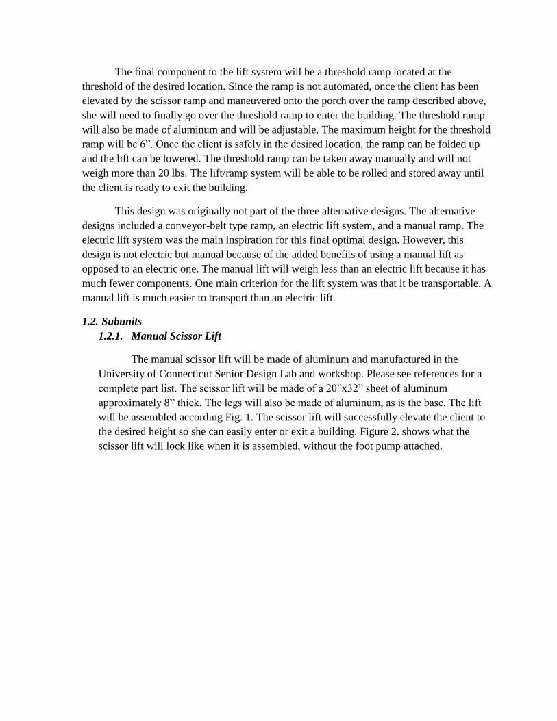
The handle lift will also be attached to the base according to Figure 1. The
release knob and release rod are located on the handle lift. This will be used in
addition to the foot pump to move the lift up and down. It will also be made of
aluminum and attached by pins on the back end of the lift. Figure 4. is top view
solidworks schematic of the scissor lift base with no hydraulic components.
Figure 4. Solidworks Schematic of Scissor Lift Base
1.2.1.2. Legs
The legs for the scissor lift will be made of 20”x¼” sheets of aluminum.
They will be cut at a 30° angle at both sides creating a parallelogram shape. They
will be connected using a bolt and washer system. The two ends on the back of
the lift will remain stationary while the two ends on the far side of the lift will
move freely. When the ramp is not in use, the two legs will sit next to each other
tucked in the base of the lift. When the lift is in use, the moveable ends of the lift
will elevate the table to the desired height, creating an “X” with the legs. The
scissor “X” design of the legs adds the necessary support for the table. Figure 5.
represents a solidworks schematic of the leg component of the scissor lift.

Figure 5. Leg Component of Scissor Lift
The legs will be attached to the base using a nut/bolt/washer system. All
components will be made of aluminum and secured in the Senior Design machine
workshop. When the legs are fully engaged it will elevate the scissor lift to a
maximum height of 33”.
1.2.1.3. Pump Assembly
The pump assembly will be attached to the base on the side of the scissor
lift furthest from the stairs. It will consist of a foot lever assembly designed using
a plate link, a holder foot pedal with lever attached, a foot lever as well as a
holder for the foot pedal. The handle lift will also aid in the function of the scissor
lift. Figure 6. is a schematic of the pump assembly attached to the base.
Figure 6. Pump Assembly

The scissor lift will have a foot operated floor lock to position the lift in
place. To raise the lift, turn the release knob clockwise until it is fully closed.
Press on the foot pedal to raise the scissor lift. To lower the lift, slowly turn
release knob counter-clockwise until the desired rate of decent is achieved. To
lock lift in position, press down on the wheel breaks located on the swivel casters
at the push handle end. Figure 7. is a schematic for the foot lever assembly. The
pump will only be controlled by the client’s caretaker. It is simple to use and will
require little maintenance.
Figure 7. Foot Lever Assembly
1.2.1.4. Table
The table for the scissor lift will be made of an aluminum sheet that is
20”x32” and 4” thick. It will consist of a top assembly designed using pins and
screws, as well as a pin retainer assembly to keep it structurally sound. The table
will be secured on the lift using 5/8 cap screws. Figure 8. is a solidworks
schematic of the table for the scissor lift.
Figure 8. Table for Scissor Lift
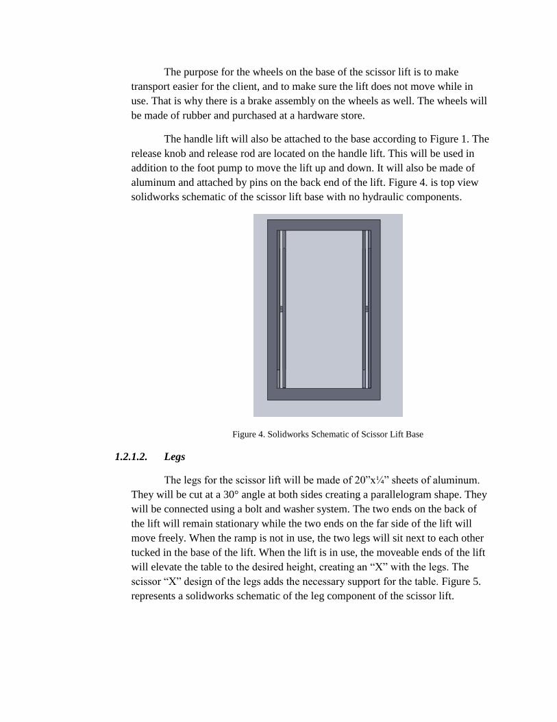
The two circles on the solidworks schematic indicated there the tie downs
will be located for the client’s wheelchair. However, the tie downs will not
resemble the two rivets featured in Fig. 8. The tie-downs used on the table of the
scissor lift will resemble those seen in Fig. 9. which are QRT M-Series restraints
with hardware. Not included in the schematic for the scissor lift table is the railing
what will be attached on either side. The railing will be implemented for the
client’s safety. The railing will be made of aluminum and will collapse on either
side so it will fall onto the lift when it is not in use. There will be lock
mechanisms in place on the railing so that while the lift is in use there is no
possibility that the railing will fall onto the client. This will be achieved using
hinges as well as pins and 5/8 screws.
Figure 9. QRT M-Series Restraint Tie-Down Kit with Straps, Pockets, and Hardware
1.2.2. Foldable Ramp
The foldable ramp will be attached to the scissor lift by a system of hinges.
Hinges were chosen so that the ramp can fold in half, and finally fold on top of the
scissor lift. The ramp will be designed using aluminum because it is light weight and easy
to transport. The foldable ramp will have lock mechanisms so that it will remain
stationary when it is in use, as well as when it is not in use. The ramp will also have two
compartments on the underside of each piece of aluminum. These hollow compartments
will store the support beams, and are not featured in Fig. 10-12. The support beams will
be held in place by a latch system and when released, the support beams will fall from the
ramp directly onto the stairs. The support beams will be adjustable up to 12” with 1”
increments. The support beams will be secured by a metal pin that will be inserted in the

correct notch to receive the desired height of the support beam to accommodate the
particular stair in which it is resting on.
1.2.2.1. Ramp Components
The ramp will be constructed using two sheets of aluminum,
approximately 20”x30”. Each piece will be approximately 3” thick. There will be
hinges placed on the ramp similar to those in Fig. 14. so that the ramp can become
collapsible and rest on top of the scissor lift when it is not in use. Figure 10 is a
solidworks representation of the ramp component of the lift mechanism when it is
completely folded, or not in use. Note that when the ramp is folded in this
manner, it will be sitting on the table of the scissor lift.
Figure 10. Folded Ramp
When the ramp is ready for use, it can simply be detached from one side
and laid out flat. There will be latches similar to that in Fig. 13 that will hold
the ramp together when it is extended. The latches will provide extra support
and stability to the device. The hinges will be placed where you can see the
two component of the ramp are attached, and the latch will be placed on the
side of the ramp where it will eventually come together. The hinges and latches
that will be used to secure the ramp are not included in Fig. 10-12.
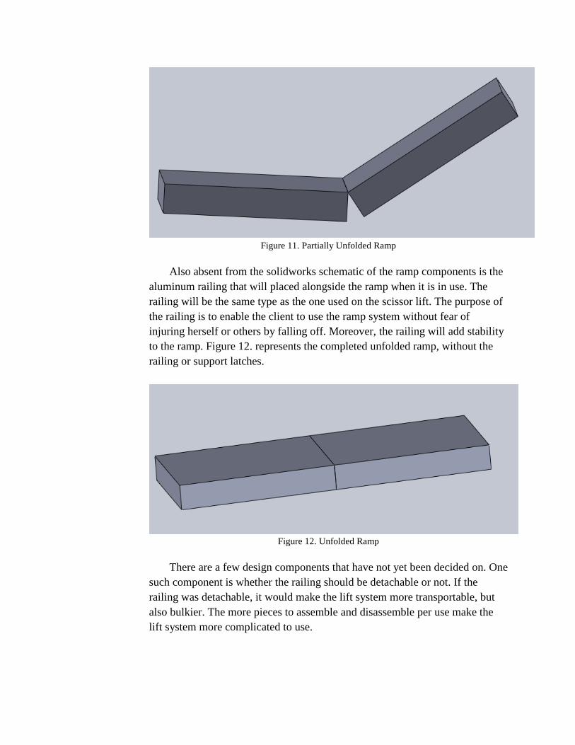
Figure 11. Partially Unfolded Ramp
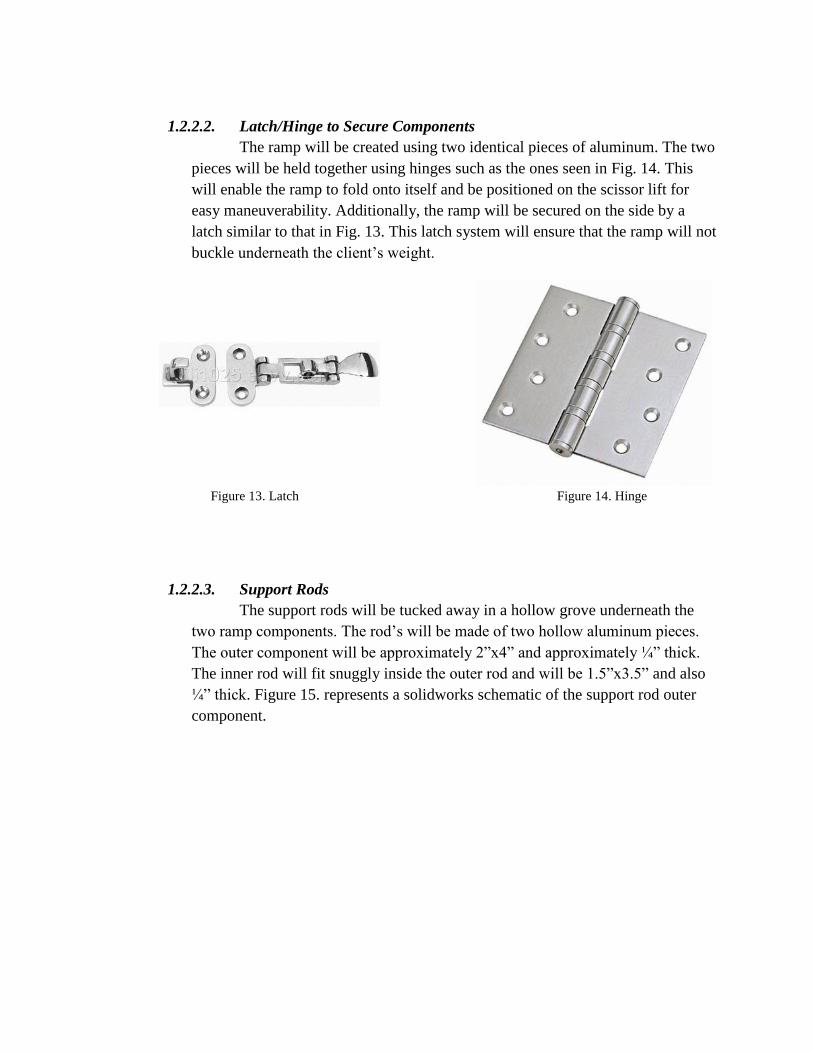
Also absent from the solidworks schematic of the ramp components is the
aluminum railing that will placed alongside the ramp when it is in use. The
railing will be the same type as the one used on the scissor lift. The purpose of
the railing is to enable the client to use the ramp system without fear of
injuring herself or others by falling off. Moreover, the railing will add stability
to the ramp. Figure 12. represents the completed unfolded ramp, without the
railing or support latches.
Figure 12. Unfolded Ramp
There are a few design components that have not yet been decided on. One
such component is whether the railing should be detachable or not. If the
railing was detachable, it would make the lift system more transportable, but
also bulkier. The more pieces to assemble and disassemble per use make the
lift system more complicated to use.
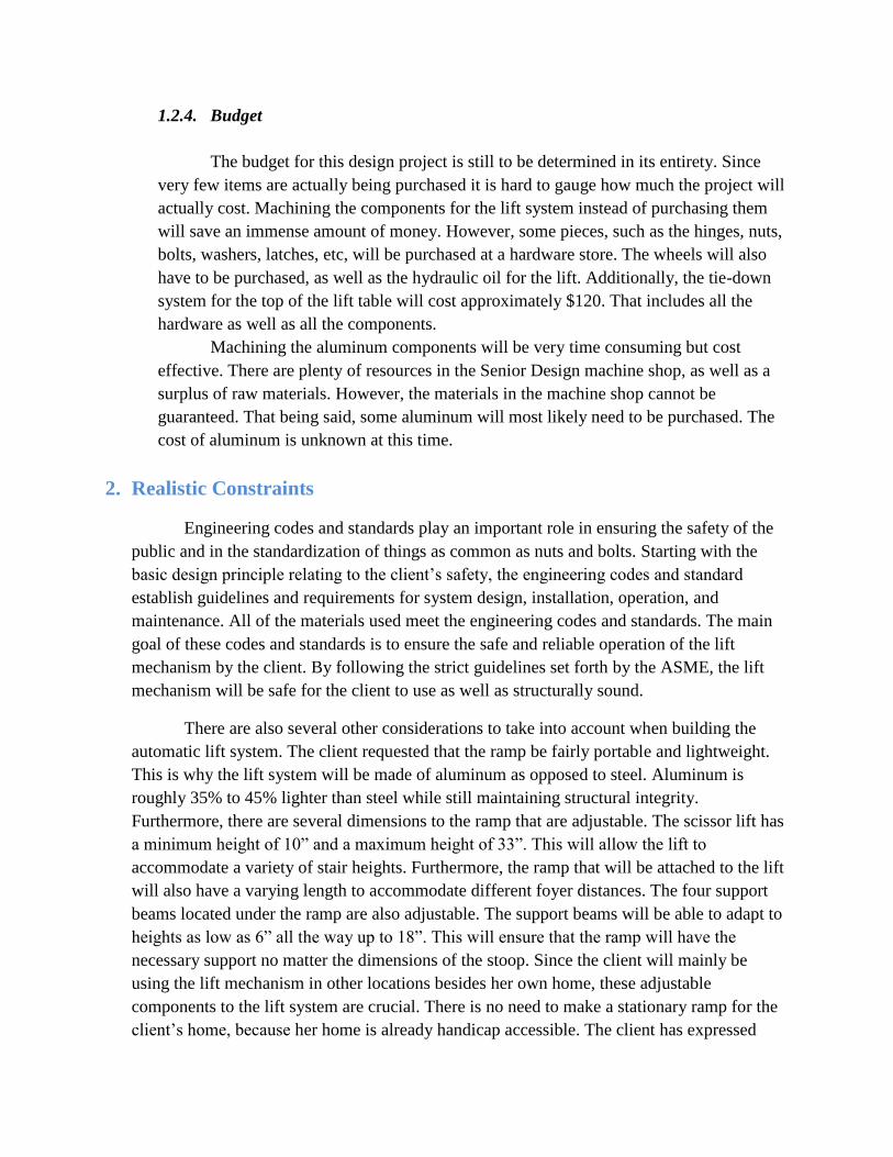
1.2.2.2. Latch/Hinge to Secure Components
The ramp will be created using two identical pieces of aluminum. The two
pieces will be held together using hinges such as the ones seen in Fig. 14. This
will enable the ramp to fold onto itself and be positioned on the scissor lift for
easy maneuverability. Additionally, the ramp will be secured on the side by a
latch similar to that in Fig. 13. This latch system will ensure that the ramp will not
buckle underneath the client’s weight.
Figure 13. Latch Figure 14. Hinge
1.2.2.3. Support Rods
The support rods will be tucked away in a hollow grove underneath the
two ramp components. The rod’s will be made of two hollow aluminum pieces.
The outer component will be approximately 2”x4” and approximately ¼” thick.
The inner rod will fit snuggly inside the outer rod and will be 1.5”x3.5” and also
¼” thick. Figure 15. represents a solidworks schematic of the support rod outer
component.

Figure 15. Support Rod Component
Each component of the rod (outer and inner) will be 10” long. The holes
that will make the rods adjustable are located 1” from the top and bottom of the
rod and are 1” apart. The holes are ½” in diameter. When the rod is fully
extended it will reach a maximum height of 18”. This is ideal for a bottom
step. When the rod is fully collapsed, it will have a minimum height of 10”.
This is ideal for a second step. Figure 16. is a solidworks schematic of the rod
when slightly adjusted.

Figure 16. Assembled Support Rod
The outer and inner component of the support beam will be held together by an
aluminum pin that is approximately 2.5” long with a ½” diameter. The pin will
fit snuggly into the appropriate notch on the support beam to ensure no
slippage when the ramp is in use. Figure 17. is a solidworks schematic of the
support pin insert that will be used for the support beams.
Figure 17. Support Insert

There will be a total of four support beams located on either side of each
ramp component. Each support beam will consist of an outer and inner piece as
well as a support pin. All components will be made of aluminum. The rods will be
stored underneath the ramp and attached by latches.
1.2.2.4. Attachment to Lift
The ramp will be attached to the ramp using hinges similar to that of Fig.
13. This will enable the ramp to fold onto itself and onto the lift. Each ramp
component is 30” long, and the table of the lift is 32” long, so the ramp
components will fit nicely on the table of the scissor lift. Additionally, the railings
will be attached using collapsible hinges so they can fold over the ramp when it is
not in use. The ramp will fold and unfold onto the lift according to Fig. 10-12.
1.2.3. Threshold Ramp
The threshold ramp will be made of aluminum and obtained by National Ramp,
Inc. The National Ramp Aluminum Threshold Ramp is lightweight, durable, and free-
standing. It is made of anodized aluminum and the ramp is also seam-free. It is adjustable
and can accommodate thresholds from ¾” to 6” high. This type of threshold ramp is ideal
for this system because ramp has great height variability and can be made suitable for all
types of environments. The ramp can also be used indoors or outdoors. The threshold
ramp is 34” wide which will nicely accommodate a standard sized door. Figure 18 is a
diagram of the threshold ramp.
Figure 18. Threshold Ramp
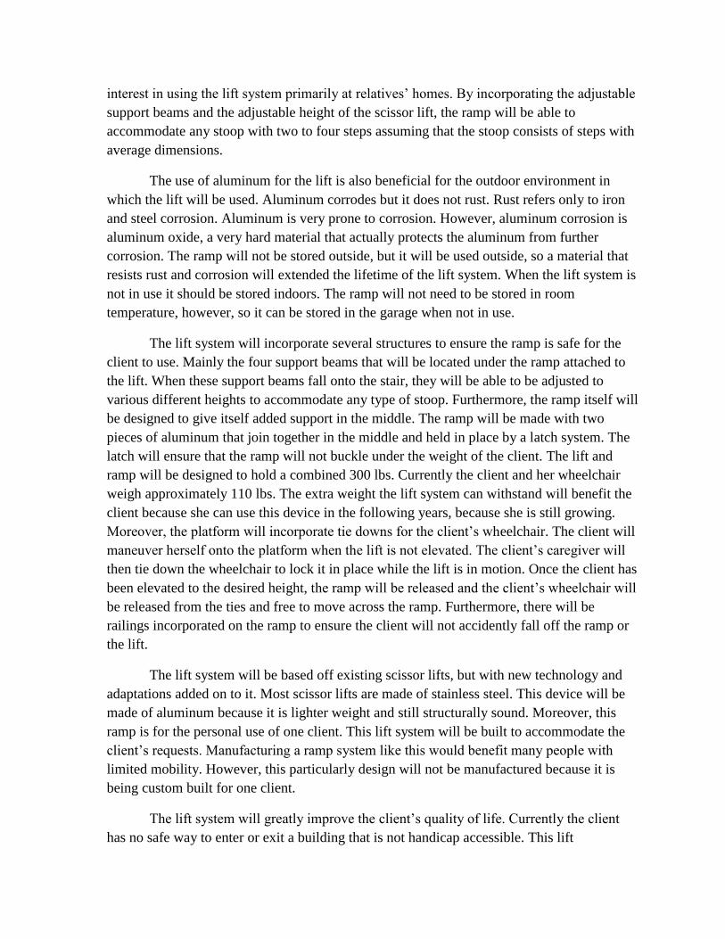
1.2.4. Budget
The budget for this design project is still to be determined in its entirety. Since
very few items are actually being purchased it is hard to gauge how much the project will
actually cost. Machining the components for the lift system instead of purchasing them
will save an immense amount of money. However, some pieces, such as the hinges, nuts,
bolts, washers, latches, etc, will be purchased at a hardware store. The wheels will also
have to be purchased, as well as the hydraulic oil for the lift. Additionally, the tie-down
system for the top of the lift table will cost approximately $120. That includes all the
hardware as well as all the components.
Machining the aluminum components will be very time consuming but cost
effective. There are plenty of resources in the Senior Design machine shop, as well as a
surplus of raw materials. However, the materials in the machine shop cannot be
guaranteed. That being said, some aluminum will most likely need to be purchased. The
cost of aluminum is unknown at this time.
2. Realistic Constraints
Engineering codes and standards play an important role in ensuring the safety of the
public and in the standardization of things as common as nuts and bolts. Starting with the
basic design principle relating to the client’s safety, the engineering codes and standard
establish guidelines and requirements for system design, installation, operation, and
maintenance. All of the materials used meet the engineering codes and standards. The main
goal of these codes and standards is to ensure the safe and reliable operation of the lift
mechanism by the client. By following the strict guidelines set forth by the ASME, the lift
mechanism will be safe for the client to use as well as structurally sound.
There are also several other considerations to take into account when building the
automatic lift system. The client requested that the ramp be fairly portable and lightweight.
This is why the lift system will be made of aluminum as opposed to steel. Aluminum is
roughly 35% to 45% lighter than steel while still maintaining structural integrity.
Furthermore, there are several dimensions to the ramp that are adjustable. The scissor lift has
a minimum height of 10” and a maximum height of 33”. This will allow the lift to
accommodate a variety of stair heights. Furthermore, the ramp that will be attached to the lift
will also have a varying length to accommodate different foyer distances. The four support
beams located under the ramp are also adjustable. The support beams will be able to adapt to
heights as low as 6” all the way up to 18”. This will ensure that the ramp will have the
necessary support no matter the dimensions of the stoop. Since the client will mainly be
using the lift mechanism in other locations besides her own home, these adjustable
components to the lift system are crucial. There is no need to make a stationary ramp for the
client’s home, because her home is already handicap accessible. The client has expressed
interest in using the lift system primarily at relatives’ homes. By incorporating the adjustable
support beams and the adjustable height of the scissor lift, the ramp will be able to
accommodate any stoop with two to four steps assuming that the stoop consists of steps with
average dimensions.
The use of aluminum for the lift is also beneficial for the outdoor environment in
which the lift will be used. Aluminum corrodes but it does not rust. Rust refers only to iron
and steel corrosion. Aluminum is very prone to corrosion. However, aluminum corrosion is
aluminum oxide, a very hard material that actually protects the aluminum from further
corrosion. The ramp will not be stored outside, but it will be used outside, so a material that
resists rust and corrosion will extended the lifetime of the lift system. When the lift system is
not in use it should be stored indoors. The ramp will not need to be stored in room
temperature, however, so it can be stored in the garage when not in use.
The lift system will incorporate several structures to ensure the ramp is safe for the
client to use. Mainly the four support beams that will be located under the ramp attached to
the lift. When these support beams fall onto the stair, they will be able to be adjusted to
various different heights to accommodate any type of stoop. Furthermore, the ramp itself will
be designed to give itself added support in the middle. The ramp will be made with two
pieces of aluminum that join together in the middle and held in place by a latch system. The
latch will ensure that the ramp will not buckle under the weight of the client. The lift and
ramp will be designed to hold a combined 300 lbs. Currently the client and her wheelchair
weigh approximately 110 lbs. The extra weight the lift system can withstand will benefit the
client because she can use this device in the following years, because she is still growing.
Moreover, the platform will incorporate tie downs for the client’s wheelchair. The client will
maneuver herself onto the platform when the lift is not elevated. The client’s caregiver will
then tie down the wheelchair to lock it in place while the lift is in motion. Once the client has
been elevated to the desired height, the ramp will be released and the client’s wheelchair will
be released from the ties and free to move across the ramp. Furthermore, there will be
railings incorporated on the ramp to ensure the client will not accidently fall off the ramp or
the lift.
The lift system will be based off existing scissor lifts, but with new technology and
adaptations added on to it. Most scissor lifts are made of stainless steel. This device will be
made of aluminum because it is lighter weight and still structurally sound. Moreover, this
ramp is for the personal use of one client. This lift system will be built to accommodate the
client’s requests. Manufacturing a ramp system like this would benefit many people with
limited mobility. However, this particularly design will not be manufactured because it is
being custom built for one client.
The lift system will greatly improve the client’s quality of life. Currently the client
has no safe way to enter or exit a building that is not handicap accessible. This lift
mechanism will give the client a safe and reliable way to not only gain entry into her own
home, but in the homes’ of relatives or other locations that are not handicap accessible. The
portability of the ramp is also a great benefit for the client. To be able to bring this device to
several locations will enrich the client’s social experiences.
3. Safety Issues
Safety of the client is the number one priority for this design. The lift and ramp
mechanisms will need to be structurally sound and tested before the client will be able to use
the device. Most scissor lifts are made with stainless steel; the optimal design for this device
calls for the scissor lift to be made of aluminum. Mechanical testing and analysis will need to
be completed to ensure that an aluminum lift will maintain the structural and mechanical
integrity of the lift the same way stainless steel does.
There are several more mechanical safety issues involving the optimal design. Since
the design has a ramp incorporated into the scissor lift, several precautions will be taken to
ensure the ramp will not buckle underneath the client’s weight. The client and her wheelchair
weigh approximately 110 pounds. The scissor lift and ramp will hold approximately 300
pounds. The four support beams located underneath the ramp will add support to the ramp.
The support beams will lie on the steps and hold the ramp up when it is in use. Additionally,
the ramp will be made of two aluminum pieces secured by a hinge/latch system. When the
ramp is in use, the latch will be secured across the two pieces of aluminum that comprise the
ramp. This feature also adds mechanical support to the lift system. Furthermore, there will be
a railing attached to the lift and the ramp when it is in use. This will provide the client with
additional security when using the lift system. The railing will ensure that the client will
remain on the ramp at all times while in use, even if the client were to lose control of her
wheelchair. The scissor lift will also have a foot operated floor lock to position the lift in
place. To raise the lift, turn the release knob clockwise until it is fully closed. Press on the
foot pedal to raise the scissor lift. To lower the lift, slowly turn release knob counter-
clockwise until the desired rate of decent is achieved. To lock lift in position, press down on
the wheel breaks located on the swivel casters at the push handle end. This will be controlled
by the client’s caregiver. This safety precaution is necessary so that the client cannot operate
the lift alone. This ensures the client’s safety and the sustainability of the lift system.
Routine inspection maintenance should be performed on the lift on a monthly basis to
ensure that there are no hazards to the client. The wheels should be lubricated, as well as all
pivot points with medium weight oil or light grease. The oil level will also have to be
periodically checked and filled if needed. The recommended hydraulic oil for the optimal
design is a Citgo AW32. It is very important to keep the hydraulic oil free of dirt, rust, metal
chips, water, and other contamination. This is because most problems with hydraulic systems
are caused by contamination in the oil.

4. Impact of Engineering Solutions
Engineering solutions have a major impact on society. Some impacts are positive,
such as water treatment systems, and some are negative, such as nuclear weapons. It is
critical that engineers give proper attention to the safety and cost of their products because
they are two aspects that impact all users of engineering products, and therefore society as a
whole. This optimal design incorporates several issues surrounding the impact of engineering
solutions. The lift system implemented in the optimal design is hydraulic. Therefore, there is
no pollution or greenhouse gas emission when the lift is in use. This feature of the ramp
protects the environment on a local and global spectrum. Additionally, the ramp will be
relatively inexpensive to design and create. The ramp will not be mass manufactured since it
is being custom built for one client.
The impact of this device can be observed most in the societal engineering solutions.
The main concern of the client is that she is unable to enter and exit buildings that are not
handicap accessible. Though this does not apply to public buildings, it affects any resident
location. The lift system will enable to client to visit friends and family’s homes without
embarrassment or trouble getting in and out of the home that is not handicap accessible.
Essentially, the ramp system will give the client a social benefit more than anything else.
The lift system will also be very easy to operate. You do not need to be an engineer to
use and maintain this device. The client’s primary caregivers are her parents and family
members. They will not need any special training to use this device, nor will they need to
make any major maintenance decisions. The lift system is not electronic, so there is no
troubleshooting that needs to be incorporated. Once the lift is assembled and tested, the client
will be able to easily use it without the help of any of the team members. This will give the
client the freedom she desires as well as the security her parents desire.
The social, economic, and environmental realities that surround globalization present
engineers with the challenge to understand the social context of the design process and the
global impact the design will create. The optimal design for the lift system will be beneficial
in all categories and have only positive effects in the global, environmental, economic, and
societal context.
5. Life-Long Learning
There are several new techniques learned while designing the optimal design for the
lift system. The scissor lift will be manufactured in the Senior Design Machine Shop by the
team members and it will not be purchased. Therefore the proper machine shop techniques
acquired include use of the saw mill and the lathe to create the parts needed to complete the
optimal design. Additionally, to analyze the components before they are put together,
SolidWorks will be implemented. The program used is brand new and the analysis will show

that the dimensions of the scissor lift and the ramp will be able to support the client while the
ramp is in use.
The lift system will incorporate several techniques that have never been implemented
before. None of the team members have any experience building anything like the lift
system. This includes the assembly of the hydraulic pump for the scissor lift, the ramp
system that will be attached to the lift, as well as the maneuverability of the lift system as a
whole. This brings a degree of mechanical engineering expertise to the table that has never
been implemented before.
The design project also incorporated the values of working as a team. This design
project cannot be accomplished by one person: it takes a collaborative approach to fix any
problems and assess any flaws in the design. The design will be very time consuming to
accomplish because it is mostly being machined by hand. This entails a lot of mechanical
experience as well as patience. The team members will all work together to accomplish this
design.
This design has incorporated a lot of manufacturing techniques. Each step in the
design process requires careful planning and research. Since the beginning of the design
process, the lift system has gone though several changes. The optimal design outlined in this
report is different from each of the alternative designs. There are several factors that
contribute to the final design, such as materials, environmental properties, workspaces, as
well as competency.
6. References
http://www.abledata.com/abledata.cfm?pageid=19327&top=10643&ksectionid=1932
7&productid=201563&trail=0&discontinued=0
http://files.asme.org/ASMEORG/Publications/Codes/5134.pdf
http://www.omni.com/products/Tilters/media/documents/downloads/Hydraulic_SL_
manual.pdf
http://images.harborfreight.com/manuals/91000-91999/91315.pdf
http://www.amazon.com/Automotive-Restraint-Tie-Down-Pockets-
Hardware/dp/B005BQUQ6G