optics in astronomy - interferometry -
DESCRIPTION
Optics in Astronomy - Interferometry -. Oskar von der Lühe Kiepenheuer-Institut für Sonnenphysik Freiburg, Germany. Contents. Fundamentals of interferometry Concepts of interferometry Practical interferometry. Concepts of interferometry Elements of an interferometer Baselines - PowerPoint PPT PresentationTRANSCRIPT
Optics in Astronomy- Interferometry -
Oskar von der LüheKiepenheuer-Institut für Sonnenphysik
Freiburg, Germany
September 2002 Optics in Astronomy 2
Contents
• Fundamentals of interferometry
• Concepts of interferometry
• Practical interferometry
• Concepts of interferometry– Elements of an interferometer
– Baselines
– Projected baselines
– Array configuration and Earth-rotational synthesis
– Methods of beam combination
– Fizeau and Michelson stellar interferometers
September 2002 Optics in Astronomy 3
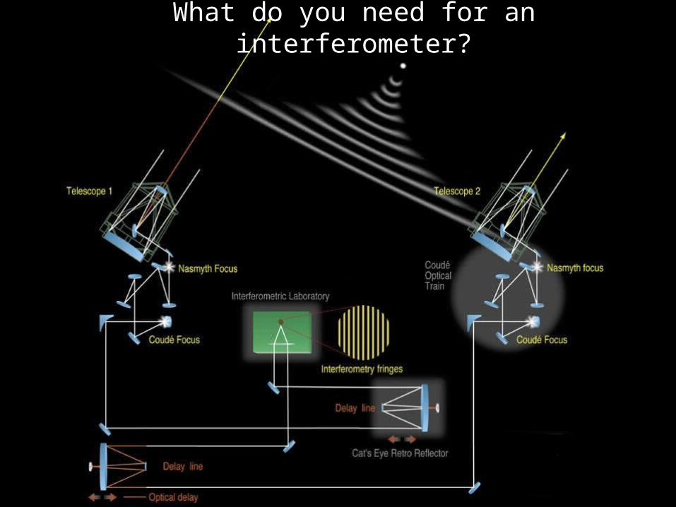
What do you need for an interferometer?
September 2002 Optics in Astronomy 4
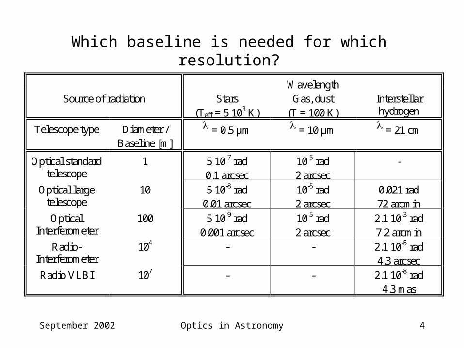
WavelengthSource of radiation Stars
(Teff = 5 103 K)Gas, dust
(T = 100 K)Interstellarhydrogen
Telescope type Diameter /Baseline [m]
= 0.5 µm = 10 µm = 21 cm
Optical standardtelescope
1 5 10-7 rad0.1 arcsec
10-5 rad2 arcsec
-
Optical largetelescope
10 5 10-8 rad0.01 arcsec
10-5 rad2 arcsec
0.021 rad72 arcmin
OpticalInterferometer
100 5 10-9 rad0.001 arcsec
10-5 rad2 arcsec
2.1 10-3 rad7.2 arcmin
Radio-Interferometer
104 - - 2.1 10-5 rad4.3 arcsec
Radio VLBI 107 - - 2.1 10-8 rad4.3 mas
Which baseline is needed for which resolution?
September 2002 Optics in Astronomy 5
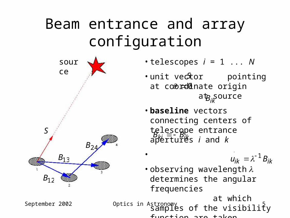
Beam entrance and array configuration
S
source
12B
13B 24B
• telescopes i = 1 ... N
• unit vector pointing at coordinate origin at source
• baseline vectors connecting centers of telescope entrance apertures i and k
•
• observing wavelength determines the angular frequencies at which samples of the visibility function are taken
S
ikB
ikki BB
ikik Bu 1
0
September 2002 Optics in Astronomy 6
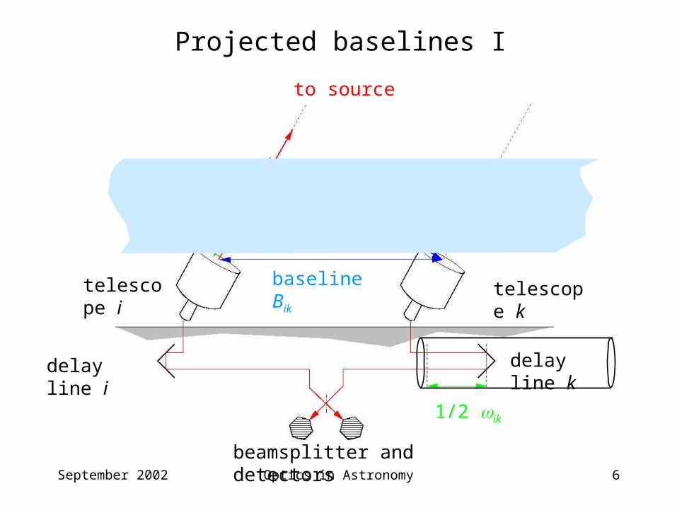
Projected baselines I
baseline Bik telescope ktelescope i
to source
projected baseline Bik‘
geometric delay wik
1/2 ik
beamsplitter and detectors
delay line i delay line k
September 2002 Optics in Astronomy 7
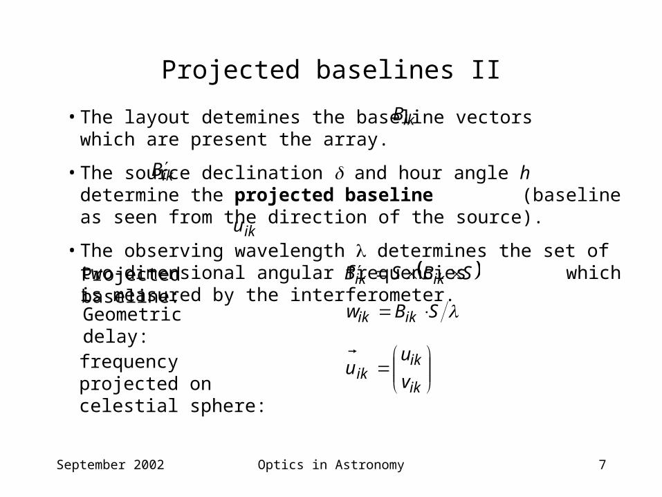
Projected baselines II
• The layout detemines the baseline vectors which are present the array.
• The source declination and hour angle h determine the projected baseline (baseline as seen from the direction of the source).
• The observing wavelength determines the set of two-dimensional angular frequencies which is measured by the interferometer.
ikB
ikB
ik
ikik v
uu
Projected baseline:
iku
SBSB ikik
Geometric delay: SBw ikik
frequency projected on celestial sphere:
September 2002 Optics in Astronomy 8
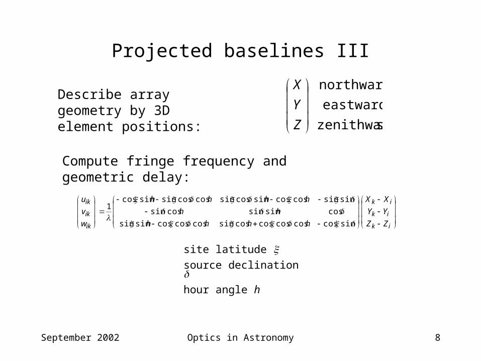
Projected baselines III
Describe array geometry by 3D element positions:
szenithward
eastwards
northwards
Z
Y
X
ik
ik
ik
ik
ik
ik
ZZ
YY
XX
hhhh
hh
hhhh
w
v
u
sincoscoscoscoscossincoscoscossinsin
cossinsincossin
sinsincoscossincossincoscossinsincos1
Compute fringe frequency and geometric delay:
site latitude source declination hour angle h
September 2002 Optics in Astronomy 9
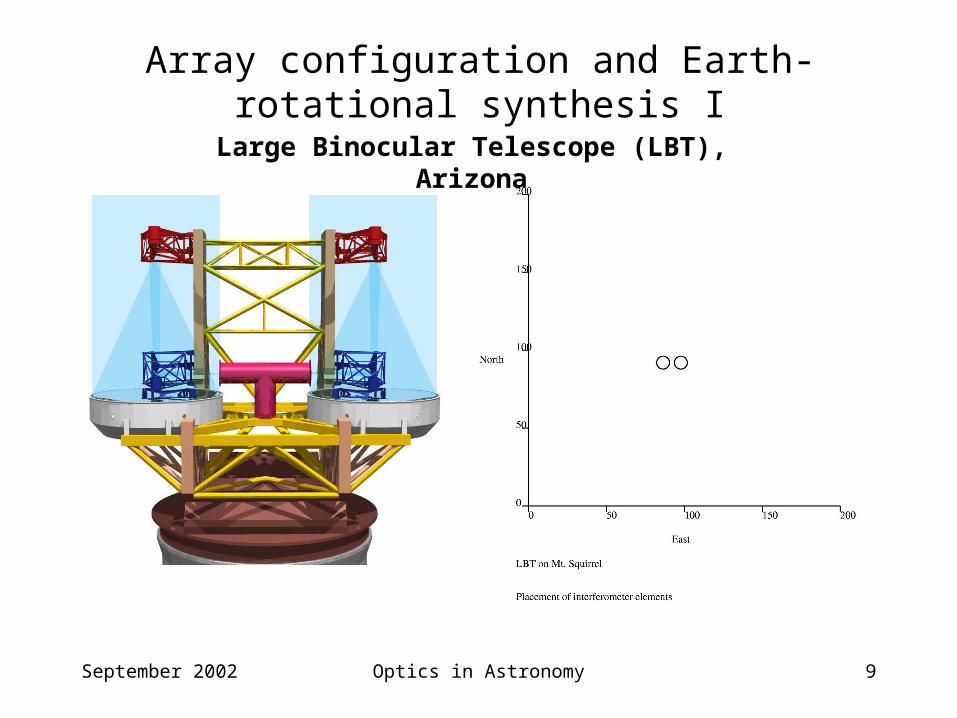
Array configuration and Earth-rotational synthesis I
Large Binocular Telescope (LBT), Arizona
September 2002 Optics in Astronomy 10
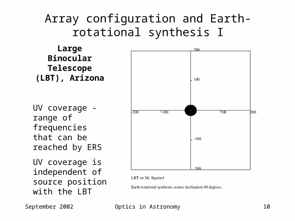
Array configuration and Earth-rotational synthesis I
Large Binocular Telescope (LBT),
Arizona
UV coverage - range of frequencies that can be reached by ERS
UV coverage is independent of source position with the LBT
September 2002 Optics in Astronomy 11
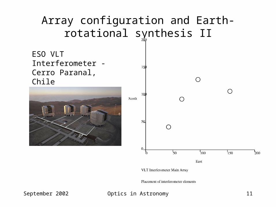
Array configuration and Earth-rotational synthesis II
ESO VLT Interferometer - Cerro Paranal, Chile
September 2002 Optics in Astronomy 12
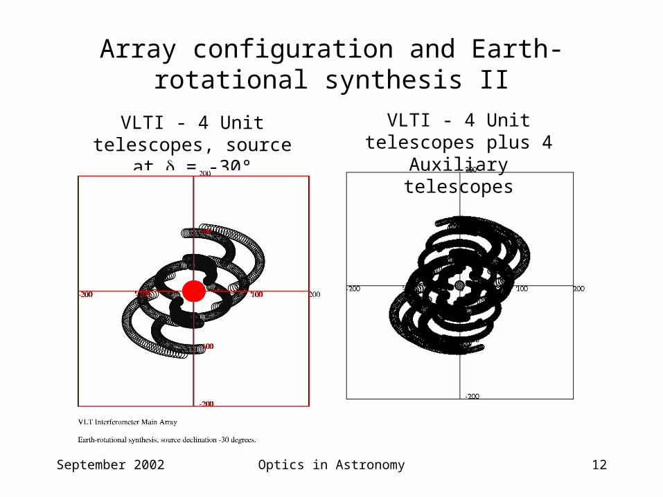
Array configuration and Earth-rotational synthesis II
VLTI - 4 Unit telescopes, source at = -30°
VLTI - 4 Unit telescopes plus 4 Auxiliary telescopes
September 2002 Optics in Astronomy 13
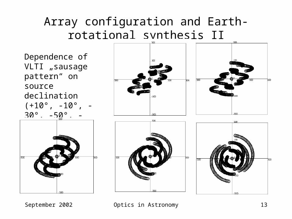
Array configuration and Earth-rotational synthesis II
Dependence of VLTI „sausage pattern“ on source declination (+10°, -10°, -30°, -50°, -70°)
September 2002 Optics in Astronomy 14
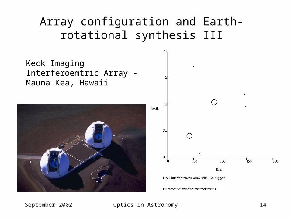
Array configuration and Earth-rotational synthesis III
Keck Imaging Interferoemtric Array - Mauna Kea, Hawaii
September 2002 Optics in Astronomy 15
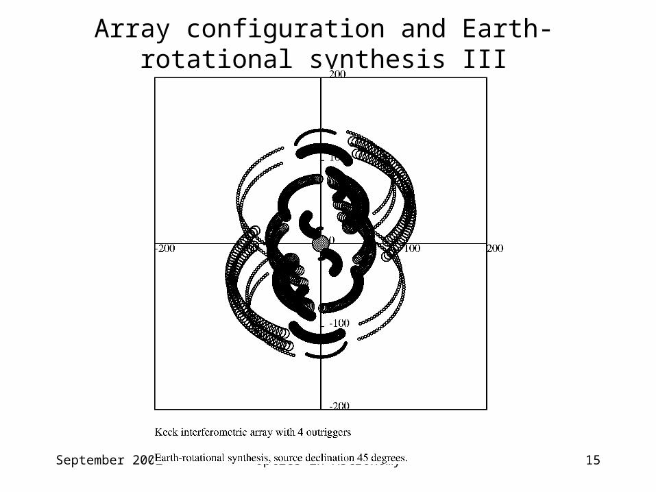
Array configuration and Earth-rotational synthesis III
September 2002 Optics in Astronomy 16
Principle of a Multiple Telescope Interferometer
Telescopes i, ..., k track sources during observation• Baselines between telescopes rotate with Earth• "Projected" baselines change with source declination and hour
angle extended coverage of Fourier ("UV") plane Electromagnetic fields are superimposed at point of beam
combination• Geometric delays changes with source declination and hour
angle optical delay tracking required Off-set sources suffer a differential geometric delay
differential optical delay tracking required
September 2002 Optics in Astronomy 17
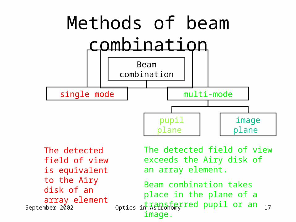
Methods of beam combination
The detected field of view is equivalent to the Airy disk of an array element
Beam combination
single mode multi-mode
pupil plane image plane
The detected field of view exceeds the Airy disk of an array element.
Beam combination takes place in the plane of a transferred pupil or an image.
September 2002 Optics in Astronomy 18
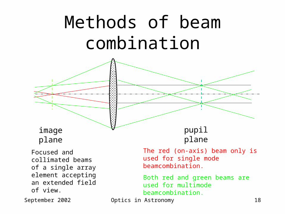
Methods of beam combination
Focused and collimated beams of a single array element accepting an extended field of view.
image plane pupil plane
The red (on-axis) beam only is used for single mode beamcombination.
Both red and green beams are used for multimode beamcombination.
September 2002 Optics in Astronomy 19
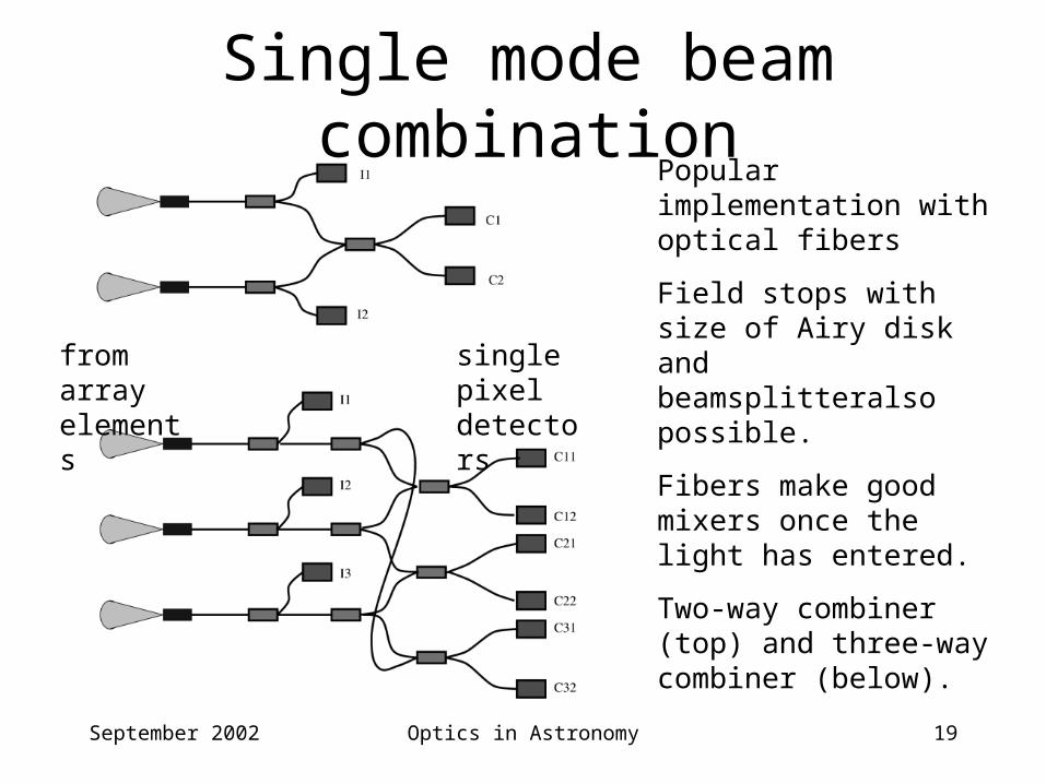
Single mode beam combinationPopular implementation with optical fibers
Field stops with size of Airy disk and beamsplitteralso possible.
Fibers make good mixers once the light has entered.
Two-way combiner (top) and three-way combiner (below).
from array elements
single pixel detectors
September 2002 Optics in Astronomy 20
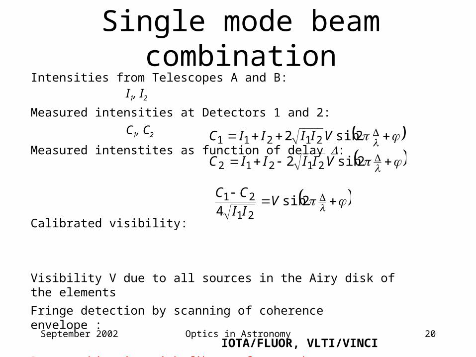
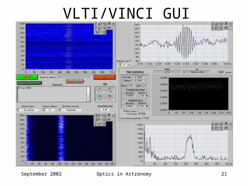
Single mode beam combinationIntensities from Telescopes A and B: I1, I2
Measured intensities at Detectors 1 and 2: C1, C2
Measured intenstites as function of delay :
Calibrated visibility:
Visibility V due to all sources in the Airy disk of the elements
Fringe detection by scanning of coherence envelope :
IOTA/FLUOR, VLTI/VINCI
Beam combination with fibers of more than two elements prone to baseline dependent errors!
2sin2
2sin2
21212
21211
VIIIIC
VIIIIC
2sin
4 21
21 VII
CC
September 2002 Optics in Astronomy 21
VLTI/VINCI GUI
September 2002 Optics in Astronomy 22
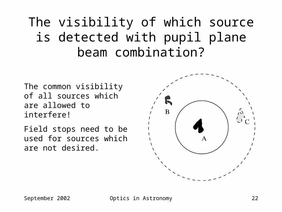
The visibility of which source is detected with pupil plane beam combination?
The common visibility of all sources which are allowed to interfere!
Field stops need to be used for sources which are not desired.
September 2002 Optics in Astronomy 23
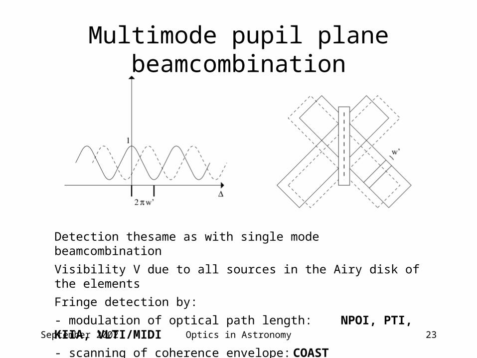
Multimode pupil plane beamcombination
Detection thesame as with single mode beamcombination
Visibility V due to all sources in the Airy disk of the elements
Fringe detection by:
- modulation of optical path length: NPOI, PTI, KIIA, VLTI/MIDI
- scanning of coherence envelope: COAST
September 2002 Optics in Astronomy 24
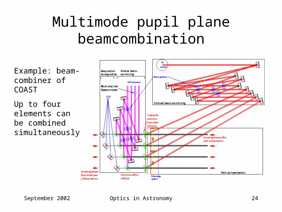
Multimode pupil plane beamcombination
Example: beam-combiner of COAST
Up to four elements can be combined simultaneously
September 2002 Optics in Astronomy 25
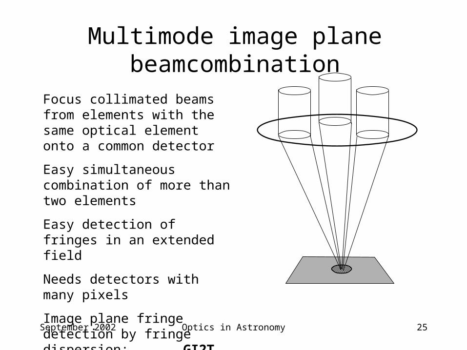
Multimode image plane beamcombination
Focus collimated beams from elements with the same optical element onto a common detector
Easy simultaneous combination of more than two elements
Easy detection of fringes in an extended field
Needs detectors with many pixels
Image plane fringe detection by fringe dispersion: GI2T
September 2002 Optics in Astronomy 26
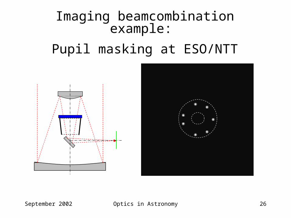
Imaging beamcombination example:
Pupil masking at ESO/NTT
September 2002 Optics in Astronomy 27
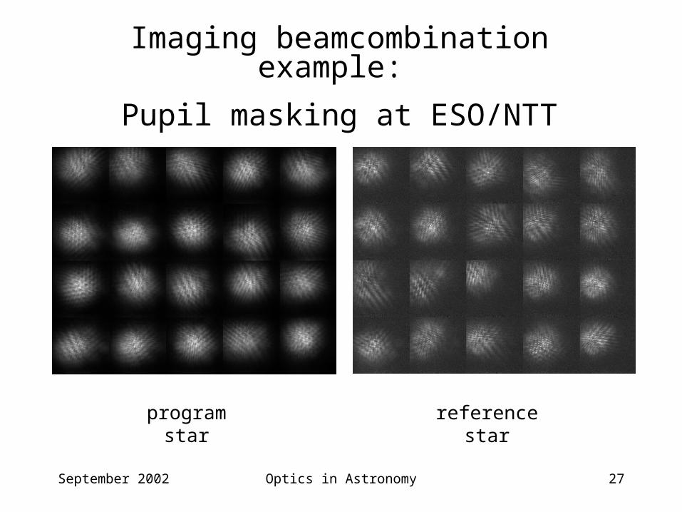
Imaging beamcombination example:
Pupil masking at ESO/NTT
program star reference star
September 2002 Optics in Astronomy 28
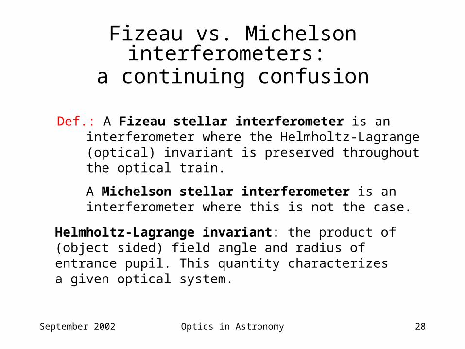
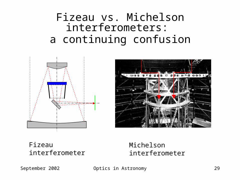
Fizeau vs. Michelson interferometers: a continuing confusion
Def.: A Fizeau stellar interferometer is an interferometer where the Helmholtz-Lagrange (optical) invariant is preserved throughout the optical train.
A Michelson stellar interferometer is an interferometer where this is not the case.
Helmholtz-Lagrange invariant: the product of (object sided) field angle and radius of entrance pupil. This quantity characterizes a given optical system.
September 2002 Optics in Astronomy 29
Fizeau vs. Michelson interferometers: a continuing confusion
Fizeau interferometer Michelson interferometer
September 2002 Optics in Astronomy 30
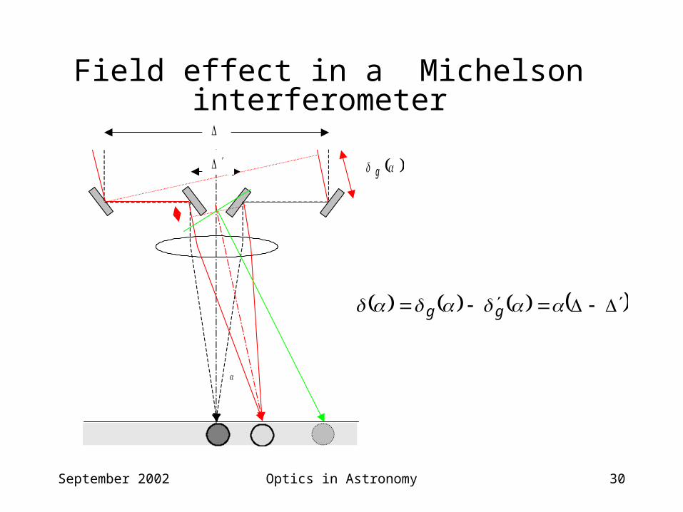
Field effect in a Michelson interferometer
g
gg