optibar p 3050 c - krohne · pdf fileblind version position correction, zero and measurement...
TRANSCRIPT

OPTIBAR P 3050 COPTIBAR P 3050 COPTIBAR P 3050 COPTIBAR P 3050 C Technical DatasheetTechnical DatasheetTechnical DatasheetTechnical Datasheet
Compact pressure transmitter with internal diaphragm
• Robust design with internal stainless steel diaphragm• Vacuum and overpressure resistant versions for absolute and gauge pressure• Very short response times (< 50 ms)
© KROHNE 02/2012 - 4001822001 - TD OPTIBAR P3050C R01 en

CONTENTS
2 www.krohne.com 02/2012 - 4001822001 - TD OPTIBAR P3050C R01 en
OPTIBAR P 3050 C
1 Product features 3
1.1 Compact pressure transmitter ........................................................................................ 31.2 Options and variants......................................................................................................... 51.3 Measuring principle.......................................................................................................... 6
2 Technical data 8
2.1 Technical data................................................................................................................... 82.2 Pressure ranges............................................................................................................. 102.3 Dimensions and weights ................................................................................................ 11
3 Installation 12
3.1 Intended use ................................................................................................................... 123.2 Technical limits .............................................................................................................. 123.3 Permissible products ..................................................................................................... 123.4 Installation specifications .............................................................................................. 123.5 Installation...................................................................................................................... 13
3.5.1 Humidity ................................................................................................................................ 133.5.2 Pressure connection via impulse line .................................................................................. 13
3.6 Ventilating the pressure sensor..................................................................................... 13
4 Electrical connections 14
4.1 Safety instructions.......................................................................................................... 144.2 Notes for electrical cables ............................................................................................. 14
4.2.1 Requirements for signal cables provided by the customer ................................................. 154.2.2 Laying electrical cables correctly......................................................................................... 154.2.3 Connection to the feed unit................................................................................................... 15
4.3 Connection in the terminal compartment ..................................................................... 164.4 Grounding the measuring device ................................................................................... 17
5 Ordering information 18

PRODUCT FEATURES 1
3
OPTIBAR P 3050 C
www.krohne.com02/2012 - 4001822001 - TD OPTIBAR P3050C R01 en
1.1 Compact pressure transmitter
With its industry standard process connections the OPTIBAR P 3050 COPTIBAR P 3050 COPTIBAR P 3050 COPTIBAR P 3050 C is universally used for general purpose pressure applications. The transmitter features superb accuracy over a wide temperature and pressure range, compact stainless steel housing, rapid response times and outstanding reproducibility and long term stability.
These features are made possible by using sensors which are extremely stable across a wide range of temperatures and pressure ranges. Additional digital compensation reduces the temperature dependence on the pressure measurement.
The measuring cell itself is completely isolated from the actual process via a stainless steel (1.4404 / 316L) diaphragm.
The electronics and the optional display are located in a stainless steel housing ventilated through a Gore-Tex® filter. This ensures that the pressure transmitter is resistant to moisture, shocks and vibration.
The protection category IP65 or IP67 depends on the selection of electrical cable glands.
An internally located push button makes it possible to easily adjust the zero point and measuring range for quick start-up.
(Version with LCD display)
1 LCD display (optional)2 Grounding connection (Ground)3 Process connection4 Stainless steel housing

1 PRODUCT FEATURES
4
OPTIBAR P 3050 C
www.krohne.com 02/2012 - 4001822001 - TD OPTIBAR P3050C R01 en
Highlights• Measuring accuracy ±0.1%• Measuring ranges: 0.5...200 bar abs. / 7...2900 psi abs.; 0.2...200 bar rel. / 3...2900 psi rel.• 2-wire device (4...20 mA)• Corrosion-resistant stainless steel housing (316L)• Internal, fully welded stainless steel diaphragm (316L)• Easily programmable for a wide range of applications• A variety of process connections available• Optional LCD display with intuitive user concept
Industries• Iron and Steel• Water & wastewater• Automation
Applications• Absolute and gauge pressure measurement of gases, vapours and liquids• Hydrostatic level measurement in containers

PRODUCT FEATURES 1
5
OPTIBAR P 3050 C
www.krohne.com02/2012 - 4001822001 - TD OPTIBAR P3050C R01 en
1.2 Options and variants
Blind version
Version with LCD display
Shut-off valve (optional)
• Extremely robust design• Start-up using internal push button• Compact dimensions
• Easy setup of all configuration parameters via display.
• Simple and intuitive handling using 4 push buttons
• ½" NPT to ½" NPT• Separate process and air valve• High quality stainless steel construction

1 PRODUCT FEATURES
6
OPTIBAR P 3050 C
www.krohne.com 02/2012 - 4001822001 - TD OPTIBAR P3050C R01 en
1.3 Measuring principle
The process pressure is transmitted from the metal diaphragm (7) via the liquid fill behind it (5) directly to the silicone measuring cell (3). The embedded piezoresistive measuring elements on the silicone diaphragm (4) experience a corresponding strain which is then converted via a Wheatstone Bridge circuit to a voltage proportional to the applied process pressure.
Absolute pressure, gauge pressure and vacuum can be measured using this measuring principle.
Figure 1-1: Measuring principle for pressure measurement
1 Signal cables of measuring bridge2 Ventilation (only with gauge pressure transmitters)3 Silicone cell4 Silicone diaphragm with piezoresistive elements5 Liquid fill6 Process pressure "P"7 Metal diaphragm
PRODUCT FEATURES 1
7
OPTIBAR P 3050 C
www.krohne.com02/2012 - 4001822001 - TD OPTIBAR P3050C R01 en
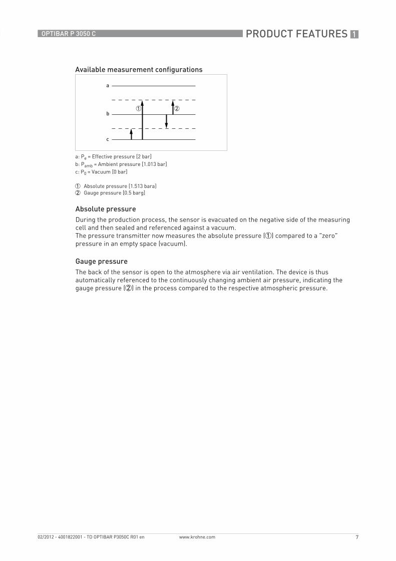
Absolute pressureDuring the production process, the sensor is evacuated on the negative side of the measuring cell and then sealed and referenced against a vacuum.The pressure transmitter now measures the absolute pressure (1) compared to a "zero" pressure in an empty space (vacuum).
Gauge pressureThe back of the sensor is open to the atmosphere via air ventilation. The device is thus automatically referenced to the continuously changing ambient air pressure, indicating the gauge pressure (2) in the process compared to the respective atmospheric pressure.
Available measurement configurations
a: Pe = Effective pressure [2 bar]b: Pamb = Ambient pressure [1.013 bar]c: P0 = Vacuum [0 bar]
1 Absolute pressure [1.513 bara]2 Gauge pressure [0.5 barg]
2 TECHNICAL DATA
8
OPTIBAR P 3050 C
www.krohne.com 02/2012 - 4001822001 - TD OPTIBAR P3050C R01 en
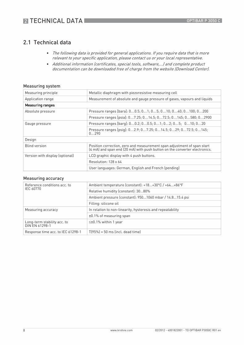
2.1 Technical data
• The following data is provided for general applications. If you require data that is more relevant to your specific application, please contact us or your local representative.
• Additional information (certificates, special tools, software,...) and complete product documentation can be downloaded free of charge from the website (Download Center).
Measuring systemMeasuring principle Metallic diaphragm with piezoresistive measuring cell
Application range Measurement of absolute and gauge pressure of gases, vapours and liquids
Measuring rangesMeasuring rangesMeasuring rangesMeasuring ranges
Absolute pressure Pressure ranges [bara]: 0…0.5; 0…1; 0…5; 0…10; 0…40; 0…100; 0…200
Pressure ranges [psia]: 0…7.25; 0…14.5; 0…72.5; 0…145; 0…580; 0…2900
Gauge pressure Pressure ranges [barg]: 0…0.2; 0…0.5; 0…1; 0…2; 0…5; 0…10; 0…20
Pressure ranges [psig]: 0…2.9; 0…7.25; 0…14.5; 0…29; 0…72.5; 0…145; 0…290
Design
Blind version Position correction, zero and measurement span adjustment of span start (4 mA) and span end (20 mA) with push button on the converter electronics.
Version with display (optional) LCD graphic display with 4 push buttons.
Resolution: 128 x 64
User languages: German, English and French (pending)
Measuring accuracyReference conditions acc. to IEC 60770
Ambient temperature (constant): +18...+30°C / +64...+86°F
Relative humidity (constant): 30...80%
Ambient pressure (constant): 950...1060 mbar / 14.8...15.4 psi
Filling: silicone oil
Measuring accuracy In relation to non-linearity, hysteresis and repeatability
±0.1% of measuring span
Long-term stability acc. to DIN EN 61298-1
≤±0.1% within 1 year
Response time acc. to IEC 61298-1 T(95%) = 50 ms (incl. dead time)

TECHNICAL DATA 2
9
OPTIBAR P 3050 C
www.krohne.com02/2012 - 4001822001 - TD OPTIBAR P3050C R01 en
Operating conditionsTemperature limitsTemperature limitsTemperature limitsTemperature limits
Operating temperature Blind version: -40…+85°C / -40...+185°F
With LCD graphic display: -20…+70°C / -4…+158°F
Ambient temperatures below -10°C / +14°F may affect the readability of the display.
Process temperature -40…+85°C / -40...+185°F
Storage temperature -20…+70°C / -4…+158°F
Other conditionsOther conditionsOther conditionsOther conditions
Protection category acc. to IEC 529 / EN 60529
Standard: IP65
Optional: IP67 with internally ventilated cable for gauge pressure sensors
Installation conditionsInstallation Can be installed in any position, zero point or position correction may be
required following installation.
Maximum error through mounting position: <3.5 mbar / <0.05 psi
Dimensions and weights For detailed information refer to section "Dimensions and weights".
MaterialsWetted parts Stainless steel W.1.4404 (AISI 316L)
Non-wetted parts Stainless steel W.1.4404 (AISI 316L)
Internal housing cover gasket: EPDM
Version with display: Makrolon®
Process connectionsStandard G½-B acc. to DIN EN 837-1
NPT versions ½"-14 NPT - female
½"-14 NPT - male
Process connections with flush mounted diaphragm
In preparation
Electrical connectionSupply voltage 12...45 VDC
Output signal 4...20 mA, 2-wire
Damping 0.1 s
Max. load resistance (current output) RLoad [KΩ] = (UB [V] - 12 V) / alarm current max. [mA]with UB = supply voltage
Initialisation time 10 s
Alarm current Configurable as high alarm (21 mA) and low alarm (3.6 mA) using optional LCD display
Cable feedthroughs M16 in plastic, nickel-plated brass or 316L stainless steel

2 TECHNICAL DATA
10
OPTIBAR P 3050 C
www.krohne.com 02/2012 - 4001822001 - TD OPTIBAR P3050C R01 en
2.2 Pressure ranges
Gauge pressure
Absolute pressure
Approvals and certificatesCE The device fulfils the statutory requirements of the EC directives. The
manufacturer certifies that these requirements have been met by applying the CE marking.
Electromagnetic compatibility (EMC) Electromagnetic influence < 0.5% of measuring span
EMC conformity for EN 61326-1 (5/2006)
NAMUR NE 43
Order code Pressure range Maximum working pressure
Smallest calibratable span
Low pressure resistance pabs.
[bar] / [psi] [bar] [bar] [bar]
1 -0.2...0.2 / -3...3 2.5 0.02 0.05
2 -0.5...0.5 / -7...7 2.5 0.05 0.05
3 -1...1 / -15...15 3 0.1 0.05
4 -1...2 / -15...145 4 0.2 0.05
5 -1...5 / -15...72 7 0.5 0.05
6 -1...10 / -15...145 15 1 0.05
7 -1...20 / -15...290 30 2 0.05
Order code Pressure range Maximum working pressure
Smallest calibratable span
Low pressure resistance pabs.
[bar] / [psi] [bar] [bar] [bar]
N 0...0.5 / 0...7 2.5 0.05 0.05
P 0...1 / 0...15 3 0.01 0.05
R 0...5 / 0...72 7 0.5 0.05
S 0...10 / 0...145 15 1 0.05
T 0...50 / 0...725 100 5 0.05
U 0...100 / 0...1450 200 10 0.05
V 0...200 / 0...2900 300 20 0.05

TECHNICAL DATA 2
11
OPTIBAR P 3050 C
www.krohne.com02/2012 - 4001822001 - TD OPTIBAR P3050C R01 en
2.3 Dimensions and weights
Figure 2-1: Dimensions for available process connection variants
d = WS27e = M16x1.5
1 G½ 2 ½" NPT - male3 ½" NPT - female
Version Dimensions Weight
a b c
[mm / "] [g / lb]
Process connection G½Blind version 60 / 2.4 71 / 2.8 124 / 4.9 734 / 1.60
Version with display 60 / 2.4 79 / 3.1 132 / 5.2 834 / 1.80
Process connection ½" NPT - maleBlind version 60 / 2.4 71 / 2.8 121 / 4.8 710 / 1.57
Version with display 60 / 2.4 79 / 3.1 129 / 5.1 810 / 1.78
Process connection ½" NPT - femaleBlind version 60 / 2.4 71 / 2.8 118 / 4.6 748 / 1.65
Version with display 60 / 2.4 79 / 3.1 126 / 5.0 834 / 1.80

3 INSTALLATION
12
OPTIBAR P 3050 C
www.krohne.com 02/2012 - 4001822001 - TD OPTIBAR P3050C R01 en
3.1 Intended use
The OPTIBAROPTIBAROPTIBAROPTIBAR series pressure transmitters were designed and constructed to measure the absolute pressure and gauge pressure of gases, vapours and liquids. The available measuring ranges and permitted maximum working pressures for each are indicated on the nameplate and described in "Technical Data". To observe the intended use, adhere to the following points:
• Observe the instructions in this document.• Comply with the technical limit values (for details refer to Technical limits on page 12).• Observe permissible products (for details refer to Permissible products on page 12).• Only suitably qualified personnel may install and operate the device.• Observe the generally accepted standards of good practice.
3.2 Technical limits
The device was constructed solely for use within the technical limits indicated on the nameplate and in the technical data. Applications outside of these limits are not permitted and could lead to significant risk of accident. For this reason, observe the following limits:
• Do not exceed or go below the maximum permissible pressure or vacuum.• Do not exceed or go below the indicated permissible operating temperature range.• Do not exceed or go below the indicated permissible ambient temperature.• Observe the housing protection type during use (IP67 only with internally ventilated cable!).
3.3 Permissible products
The device is designed to measure the pressure of vaporous, gaseous and liquid media. Device variants featuring recessed diaphragms are not suitable for the measurement of products containing solids or viscous and paste-like products. Prior to using any corrosive or abrasive products, the operator must check the resistance of all parts in contact with the product.
3.4 Installation specifications
The accuracy of the measurement is only guaranteed if the transmitter and accompanying impulse line(s), if any, have been correctly installed. In addition, extreme ambient conditions including large fluctuations in temperature, vibrations and shocks should be kept as far away as possible from the measuring equipment.
Responsibility for the use of the measuring devices with regard to suitability, intended use and corrosion resistance of the used materials against the measured fluid lies solely with the operator.
The manufacturer is not liable for any damage resulting from improper use or use for other than the intended purpose.
For devices used in hazardous areas, additional safety notes apply; please refer to the Ex documentation.
Observe the relevant directives, ordinances, standards and accident prevention regulations (e.g. VDE/VDI 3512, DIN 19210, VBG, Elex V, etc.).

INSTALLATION 3
13
OPTIBAR P 3050 C
www.krohne.com02/2012 - 4001822001 - TD OPTIBAR P3050C R01 en
3.5 Installation
3.5.1 Humidity
Use a suitable cable and tighten the cable gland in accordance with the recommended torque specifications. Protect the transmitter from penetrating moisture by dropping the cable down before the screw connection. Any liquids running along the cable will thus drip off before reaching the screw connection; refer to Laying electrical cables correctly on page 15. This is particularly important for unprotected installation outside or in rooms in which moisture is an issue (e.g. as a result of cleaning processes) or on cooled or heated containers.
3.5.2 Pressure connection via impulse line
Bear the following in mind when connecting the pressure connection via an impulse line:
• Select the shortest impulse line possible and lay without sharp bends.• Avoid deposits and blockages in the impulse line. Accordingly, lay the impulse line so that
such occurrences are impossible. Do not exceed a drop or rise of approx. 8% in the pipe.• Ensure that the impulse line flows freely before the connection and rinse with compressed
air or, even better, with the product itself.• When measuring liquid, the impulse line must be completely purged of air.• Run the impulse line so that trapped air (when measuring liquids) or condensate (when
measuring gas) can flow back into the process line.• Hot steam must not enter the process connection (the excess temperature will destroy the
device). To avoid this situation, a suitable water trap (such as a U-tube filled with water prior to installation) can be installed upstream from the measuring device.
• Ensure that the connection is perfectly sealed!
3.6 Ventilating the pressure sensor
In the case of gauge pressure transmitters, mechanical reasons make it necessary to charge the reference side of the pressure sensor with atmospheric pressure. Ventilation occurs in versions in IP65 via a special aerator fitted with a Gore-Tex® filter. Ensure that the ventilation opening is not covered or closed (e.g. covering over with paint not permitted).
For the IP 67 version, a vented cable fitted with a capillary tube must be used. In the process, ensure that the capillary tubes are vented in a dry room protected from moisture and that no dust or moisture can penetrate the capillary tube opening.
• Prior to installing the transmitter it is essential to verify whether the version of the device on hand completely fulfils the technical and safety requirements of the measuring point. This applies in particular to the measuring range, overpressure resistance, temperature, explosion protection and operating voltage.
• Check the materials used for the wetted parts (e.g. gasket, process connection, separating diaphragm etc.) for suitability as regards product resistance.

4 ELECTRICAL CONNECTIONS
14
OPTIBAR P 3050 C
www.krohne.com 02/2012 - 4001822001 - TD OPTIBAR P3050C R01 en
4.1 Safety instructions
4.2 Notes for electrical cables
All work on the electrical connections may only be carried out with the power disconnected. Take note of the voltage data on the nameplate!
Observe the national regulations for electrical installations!
For devices used in hazardous areas, additional safety notes apply; please refer to the Ex documentation.
Observe without fail the local occupational health and safety regulations. Any work done on the electrical components of the measuring device may only be carried out by properly trained specialists.
Look at the device nameplate to ensure that the device is delivered according to your order. Check for the correct supply voltage printed on the nameplate.
The device must be grounded to a spot in accordance with regulations in order to protect personnel against electric shocks.
Cables may only be connected when the power is switched off! Since the transmitter has no switch-off elements, overcurrent protection devices, lightning protection and/or energy isolating devices must be provided by the customer.
ELECTRICAL CONNECTIONS 4
15
OPTIBAR P 3050 C
www.krohne.com02/2012 - 4001822001 - TD OPTIBAR P3050C R01 en
4.2.1 Requirements for signal cables provided by the customer
Specifications for standard signal cables• 2 twisted double wire circuits• 20 AWG twisted, tinned copper conductors• Completely tinned copper shielding• Casing colour: grey• Colour of wires:
Pair 1: black / red; pair 2: green / white• Test voltage: ≥ 500 VAC RMS (750 VDC)• Temperature range: -40...+105°C / -40...+221°F• Capacity: ≤ 200 pF/m / 61 pF/ft• Inductance: ≤ 0.7 µH/m / 0.2 µH/ft
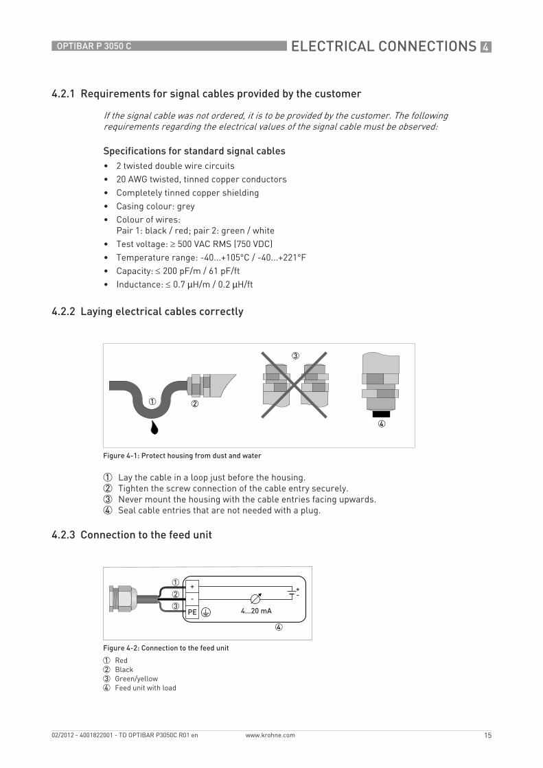
4.2.2 Laying electrical cables correctly
1 Lay the cable in a loop just before the housing.2 Tighten the screw connection of the cable entry securely.3 Never mount the housing with the cable entries facing upwards.4 Seal cable entries that are not needed with a plug.
4.2.3 Connection to the feed unit
If the signal cable was not ordered, it is to be provided by the customer. The following requirements regarding the electrical values of the signal cable must be observed:
Figure 4-1: Protect housing from dust and water
Figure 4-2: Connection to the feed unit
1 Red2 Black3 Green/yellow4 Feed unit with load
4 ELECTRICAL CONNECTIONS
16
OPTIBAR P 3050 C
www.krohne.com 02/2012 - 4001822001 - TD OPTIBAR P3050C R01 en
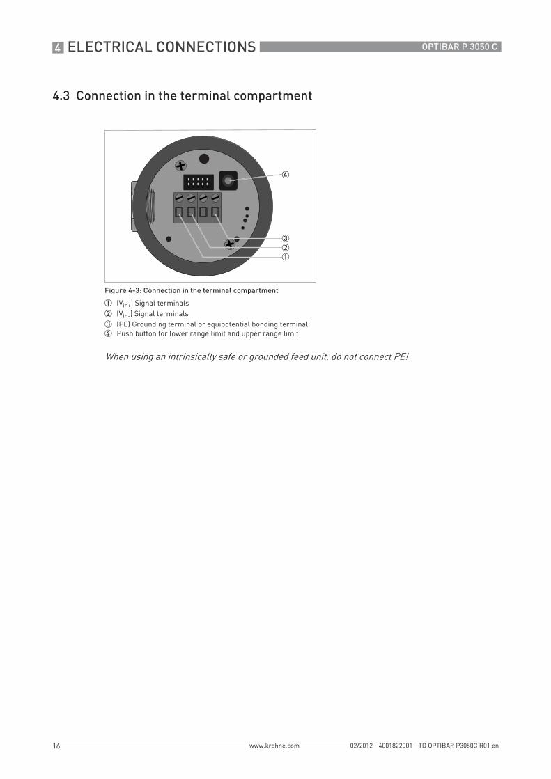
4.3 Connection in the terminal compartment
Figure 4-3: Connection in the terminal compartment
1 (Vin+) Signal terminals2 (Vin-) Signal terminals3 (PE) Grounding terminal or equipotential bonding terminal4 Push button for lower range limit and upper range limit
When using an intrinsically safe or grounded feed unit, do not connect PE!

ELECTRICAL CONNECTIONS 4
17
OPTIBAR P 3050 C
www.krohne.com02/2012 - 4001822001 - TD OPTIBAR P3050C R01 en
4.4 Grounding the measuring device
• The pressure sensor must be properly grounded.• When using an intrinsically safe or grounded feed unit, do not connect PE!• Do not use the grounding cable to connect any other electrical devices to ground at the same
time.• The pressure transmitter is connected to ground by means of a functional grounding
conductor.• In hazardous areas, grounding is used at the same time for equipotential bonding.
A ground terminal is provided on the outside of the housing to accommodate wire widths of up to 1.5 mm2.
There should be no difference in potential between the pressure sensor and the housing or protective earth of the transmitter!
Figure 4-4: Position of the ground terminal on the housing
1 Ground terminal

5 ORDERING INFORMATION
18
OPTIBAR P 3050 C
www.krohne.com 02/2012 - 4001822001 - TD OPTIBAR P3050C R01 en
The characters of the order code highlighted in light grey describe the standard.
SensorSensorSensorSensor VersionVersionVersionVersion
VGK3VGK3VGK3VGK3 0 0 Gauge pressure transmitter
1 Absolute pressure transmitter
Wetted materialsWetted materialsWetted materialsWetted materials
S 1.4404 / 316L stainless steel
Process connectionProcess connectionProcess connectionProcess connection
0 ½" NPT male
1 ½" NPT female
2 G½ acc. to DIN 837-1 (with appropriate gasket)
Measuring rangeMeasuring rangeMeasuring rangeMeasuring range
Gauge pressure [bar] / [psi]Gauge pressure [bar] / [psi]Gauge pressure [bar] / [psi]Gauge pressure [bar] / [psi]
1 -0.2...0.2 / -3...3
2 -0.5...0.5 / -7...7
3 -1...1 / -15...15
4 -1...2 / -15...145
5 -1...5 / -15...72
6 -1...10 / -15...145
7 -1...20 / -15...290
Absolute pressure [bar] / [psi]Absolute pressure [bar] / [psi]Absolute pressure [bar] / [psi]Absolute pressure [bar] / [psi]
N 0...0.5 / 0...7
P 0...1 / 0...15
R 0...5 / 0...72
S 0...10 / 0...145
T 0...50 / 0...725
U 0...100 / 0...1450
V 0...200 / 0...2900
Shut-off valveShut-off valveShut-off valveShut-off valve
0 None
1 Valve block (only available with ½" NPT male thread process connection; pressure transmitter requires ½" NPT female thread process connection)
OutputOutputOutputOutput
0 2-wire 4...20 mA (24 VDC)
Ex approvalsEx approvalsEx approvalsEx approvals
0 Non-Ex
Housing Housing Housing Housing
S 316L stainless steel
Electrical connectionElectrical connectionElectrical connectionElectrical connection
0 1 x M16 x 1.5 plastic
1 1 x M16 x 1.5 nickel-plated brass
2 1 x M16 x 1.5 316L stainless steel

ORDERING INFORMATION 5
19
OPTIBAR P 3050 C
www.krohne.com02/2012 - 4001822001 - TD OPTIBAR P3050C R01 en
DisplayDisplayDisplayDisplay
0 None
1 With integrated LCD display
Display languageDisplay languageDisplay languageDisplay language
1 English
2 German
Additional safety requirementsAdditional safety requirementsAdditional safety requirementsAdditional safety requirements
0 None
ManualsManualsManualsManuals
0 None
1 English
2 German
3 French
4 Spanish
5 Russian
6 Chinese
Sensor tagSensor tagSensor tagSensor tag
0 None
1 Stainless steel tag (40 x 20 mm)
2 Stainless steel tag (120 x 46 mm)
Private Label
0 KROHNE standard
VGK3VGK3VGK3VGK3 0 x x Order codeOrder codeOrder codeOrder code

KROHNE product overview
• Electromagnetic flowmeters
• Variable area flowmeters
• Ultrasonic flowmeters
• Mass flowmeters
• Vortex flowmeters
• Flow controllers
• Level meters
• Temperature meters
• Pressure meters
• Analysis products
• Measuring systems for the oil and gas industry
• Measuring systems for sea-going tankers
Head Office KROHNE Messtechnik GmbHLudwig-Krohne-Str. 5D-47058 Duisburg (Germany)Tel.:+49 (0)203 301 0Fax:+49 (0)203 301 10389 [email protected]
© K
RO
HN
E 02
/201
2 -
4001
8220
01 -
TD
OP
TIB
AR
P30
50C
R01
en
- Su
bjec
t to
chan
ge w
ithou
t not
ice.
The current list of all KROHNE contacts and addresses can be found at:www.krohne.com
KK
K