operator’s manual supplement - parstanafos
TRANSCRIPT

Operator’s Manual Supplement
Volumetric Capnography
L3004Revision A

Volumetric Capnography Operator’s Manual Supplement
© 2007 VIASYS® Respiratory Care Inc.
All rights reserved. No part of this document may be reproduced, stored, or transmitted in any form or by any means without the written permission of VIASYS Respiratory Care Inc., except as specifically permitted under the copyright laws of the United States of America.
AVEA is a registered trademark of VIASYS Respiratory Care Inc. VIASYS and the VIASYS logo are trademarks of VIASYS Healthcare Inc. Respironics and CAPNOSTAT are regis-tered trademarks of Respironics, Inc., and its affiliates. Other brands and their products are trademarks of their respective holders and should be noted as such.
U.S.A.VIASYS Respiratory Care Inc.1100 Bird Center DrivePalm Springs, California 92262-8099
Telephone: (800) 231-2466(1) (714) 283-2228
Fax: (1) (714) 283-8493
European Authorized RepresentativeVIASYS Healthcare GmbHLeibnizstrasse 797204 HoechbergGermany
Telephone: (49) (931) 4972-0Fax: (49) (931) 4972-423
www.viasyshealthcare.com
ii L3004

Operator’s Manual Supplement Volumetric Capnography
Revisions
Date Revision Pages Changes
September 2007 A All Release
L3004 iii
Volumetric Capnography Operator’s Manual Supplement
Safety Information
Read the following safety information before operating the ventilator. Attempting to operate the ventilator without fully understanding its features and functions may result in unsafe operating conditions.
Warnings and cautions, which are general to the use of the ventilator under all circum-stances, are included in this section. Some warnings and cautions are also inserted within the manual where they are most meaningful.
Notes are also located throughout the manual to provide additional information related to specific features.
If you have a question regarding the installation, set up, operation, or maintenance of the ventilator, contact VIASYS Respiratory Care Technical Support (refer to “Appendix A: Con-tact & Ordering Information” in the AVEA Operator’s Manual).
TermsWARNINGS identify conditions or practices that could result in serious adverse reactions or potential safety hazards.
CAUTIONS identify conditions or practices that could result in damage to the ventilator or other equipment.
NOTES identify supplemental information to help you better understand how the ventilator works.
WarningsThe warnings contained in this addendum are in addition to the warnings in the full AVEA operator’s manual.Periodically check the CO2 sensor for excessive moisture or secretion build up.
Volumetric capnography measurements require accurate measurement of delivered vol-umes. For this reason, a proximal flow sensor or circuit compliance compensation must be used. Furthermore, when circuit compliance compensation is used, and if the circuit compli-ance changes, volumetric accuracy will be altered.
A system leak, such as that caused by un-cuffed endotracheal tubes may affect flow-related readings. These include flow, pressure, dead space, CO2 production, and other respiratory mechanics parameters.
Nitrous oxide, excessive levels of oxygen, helium, and halogenated hydrocarbons can influ-ence the CO2 measurements. The AVEA compensates for oxygen and helium gas automat-ically.
iv L3004

Operator’s Manual Supplement Volumetric Capnography
Do not use CO2 measurements as the sole basis for changing ventilation parameters with-out reference to clinical condition and independent monitors such as blood gas. CO2 mea-surements may be inaccurate in the presence of a breathing circuit leak, secretions, or sensor malfunction.
Do not position the CO2 sensor or cable in any manner that may cause entanglement, stran-gulation, or accidental self-extubation. Use clips as appropriate to secure the sensor cable to the breathing circuit.
Do not use EtCO2 as basis for changing ventilation parameters without reference to clinical condition and independent monitors such as blood gas.
CautionsThe cautions contained in this addendum are in addition to the warnings in the full AVEA Operator’s Manual.The CAPNOSTAT® 5 contains no user serviceable parts.
Do not use damaged sensors or cables.
Do not sterilize or immerse sensors, except as directed in the AVEA Operator’s Manual.
Do not apply excessive tension to any sensor cable.
It is recommended that the CO2 sensor be removed from the circuit whenever an aero-solized medication is delivered. This is due to the increased viscosity of the medications, which may contaminate the sensor windows, causing the sensor to fail prematurely or to dis-play incorrect data.
L3004 v

Volumetric Capnography Operator’s Manual Supplement
vi L3004

Operator’s Manual Supplement Volumetric Capnography
Contents
Revisions - - - - - - - - - - - - - - - - - - - - - - - - - - - iiiSafety Information - - - - - - - - - - - - - - - - - - - - - - - iv
Terms - - - - - - - - - - - - - - - - - - - - - - - - - - - ivWarnings - - - - - - - - - - - - - - - - - - - - - - - - - - ivCautions - - - - - - - - - - - - - - - - - - - - - - - - - - v
Theory of Operation - - - - - - - - - - - - - - - - - - - - - - 1
Parts and Accessories- - - - - - - - - - - - - - - - - - - - - 1
Setup- - - - - - - - - - - - - - - - - - - - - - - - - - - - - - 2
Settings and Monitored Values - - - - - - - - - - - - - - - - 4Settings - - - - - - - - - - - - - - - - - - - - - - - - - - - - 4Monitored Values - - - - - - - - - - - - - - - - - - - - - - - - 6Waveforms and Loops - - - - - - - - - - - - - - - - - - - - - 8Alarms - - - - - - - - - - - - - - - - - - - - - - - - - - - - - 9
Maneuvers - - - - - - - - - - - - - - - - - - - - - - - - - - 10
Zeroing the CAPNOSTAT 5 - - - - - - - - - - - - - - - - - 12
Checking the Accuracy of the CAPNOSTAT 5- - - - - - - - 14
Cleaning - - - - - - - - - - - - - - - - - - - - - - - - - - - 16Sensor - - - - - - - - - - - - - - - - - - - - - - - - - - - - 16Airway Adaptors - - - - - - - - - - - - - - - - - - - - - - - 16
Reusable Adaptors - - - - - - - - - - - - - - - - - - - - 16Disposable Adaptors - - - - - - - - - - - - - - - - - - - 16
Appendix- - - - - - - - - - - - - - - - - - - - - - - - - - - 17Troubleshooting - - - - - - - - - - - - - - - - - - - - - - - 17Calculations - - - - - - - - - - - - - - - - - - - - - - - - - 18Specifications - - - - - - - - - - - - - - - - - - - - - - - - 22
L3004 vii

Volumetric Capnography Operator’s Manual Supplement
viii L3004
Operator’s Manual Supplement Volumetric Capnography
Theory of Operation
The CAPNOSTAT® 5 measures CO2 by using the infrared absorption technique, which has endured and evolved in the clinical setting for over the past two decades and remains the most popular and versatile technique. The principle is based on the fact that CO2 molecules absorb infrared (IR) light energy of specific wavelengths with the amount of energy absorbed being directly related to the CO2 concentration. When an IR beam is passed through a gas sample containing CO2, the electronic signal from the photo detector (which measures the remaining light energy) can be obtained. This signal is then compared to the energy of the IR source and calibrated to accurately reflect CO2 concentration in the sample.
Parts and Accessories
The VIASYS capnography system is shipped with the following items. If any item is missing or damaged, call VIASYS Respiratory Care Technical Support for a replacement.
Also available but not included:
Description Quantity
CAPNOSTAT® 5 / cable assembly 1
Adult / pediatric non-disposable airway adaptor 1
Pediatric / infant non-disposable airway adaptor 1
Description Quantity
Single-patient use adult / pediatric airway adapters
box of 10
Single-patient use neonatal / pediatric airway adapters
box of 10
5% CO2 calibration gas (±0.03%, bal N2) 1
Calibration gas pressure regulator 1
L3004 1
Parts and Accessories Operator’s Manual SupplementVolumetric Capnography
Setup
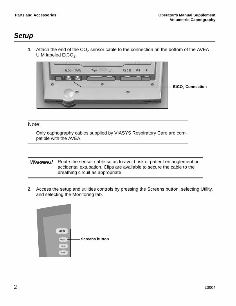
1. Attach the end of the CO2 sensor cable to the connection on the bottom of the AVEA UIM labeled EtCO2.
Note:Only capnography cables supplied by VIASYS Respiratory Care are com-patible with the AVEA.
2. Access the setup and utilities controls by pressing the Screens button, selecting Utility, and selecting the Monitoring tab.
WARNING! Route the sensor cable so as to avoid risk of patient entanglement or accidental extubation. Clips are available to secure the cable to the breathing circuit as appropriate.
EtCO2 Connection
Screens button
2 L3004

Operator’s Manual SupplementVolumetric Capnography
Parts and Accessories
3. Enable CO2 Monitoring by touching the Enable/Disable button.
Note:Capnography requires either a proximal flow sensor or circuit compliance compensation to be active
If CO2 monitoring is enabled but a proximal flow sensor or circuit compli-ance compensation is not active, an alert dialog box appears.
4. If volumetric capnography is required, add a proximal flow sensor or enable circuit com-pliance compensation (or do both), and then re-enable CO2 monitoring as described above; otherwise, only the PCO2 waveform and End-tidal CO2 monitor are available.
5. Remove the appropriate airway adaptor from its packaging and make sure it is undam-aged and ready to use.
L3004 3

Settings and Monitored Values Operator’s Manual SupplementVolumetric Capnography
6. Insert the airway adaptor into the CO2 sensor. The adaptor clicks into place when prop-erly inserted.
7. Perform the “sensor zero” procedure by following the instructions in the section “Zeroing the CAPNOSTAT 5” on page 12. The zeroing procedure must also be performed when switching between disposable and reusable airway adaptors.
8. After the sensor is successfully zeroed, place the airway adaptor and sensor into the ventilator circuit between the wye and endotracheal tube (and any adaptors) as shown in the preceding illustration.
Settings and Monitored Values
SettingsThe setup and utilities controls are accessed by pressing the Screens button, selecting Util-ity, and selecting the Monitoring tab.
4 L3004
Operator’s Manual SupplementVolumetric Capnography
Settings and Monitored Values
Capnography – Enable / DisableWhen CO2 monitoring is enabled, all CO2 monitoring and alarm functions are also enabled. When CO2 Monitoring is disabled all CO2 monitoring and alarm functions are disabled.
Range: Enable or Disable
Default: Disable
EtCO2 Averaging EtCO2 is measured for each breath. You can select the number of breaths over which the displayed EtCO2 is averaged.
Range: 1 or 8 breath(s)
Default: 8 breaths
VCO2 Averaging VCO2 is updated at one minute intervals. You select the time over which the displayed VCO2 is averaged. Also averaged over this time period are Vd, Vd/Vt, VtCO2 and VA.
Range: 3, 6, 9 or 12 minutes
Default: 6 minutes
Zero CO2
This control initiates the sensor zero procedure. This procedure needs to be done only when you switch airway adaptor types (disposable or reusable) and as part of the cali-bration check. See the section “Zeroing the CAPNOSTAT 5” on page 12.
Note:The CO2 Zero and calibration-check controls are available only when CO2 is enabled and a sensor has been connected and has completed initializa-tion. This initialization may take up to five seconds.
Calibration CheckThis control provides access to a calibration-check procedure. This procedure needs to be done only during the yearly, preventative maintenance procedure. See the section “Checking the Accuracy of the CAPNOSTAT 5” on page 14.
L3004 5

Settings and Monitored Values Operator’s Manual SupplementVolumetric Capnography
Monitored ValuesEnd Tidal CO2 (EtCO2)
The patient’s peak expired CO2 as measured and reported by the CO2 sensor in the air-way. EtCO2 is measured for each breath. The display is either a breath-by-breath mea-surement or an averaged measurement.
Range: 0 – 150 mmHg (0 – 20.0 kPa)
Resolution: 0.1 mmHg (0.01 kPa) or three significant digits (whichever is greater)
Accuracy:
± 2 mmHg for 0 – 40 mmHg
± 5% of reading for 41 – 70 mmHg
± 8% of reading for 71 – 100 mmHg
± 10% of reading for 101 – 150 mmHg
Note:The minimum differential between inspired and expired CO2 must be 5 mmHg (0.7kPa) or greater.
CO2 Elimination (VCO2)The amount of CO2 eliminated every minute. This is calculated over each minute, and then averaged over the set VCO2 averaging time.
Range: 0 – 999 mL/min
Resolution: 0.1 mL or three significant digits (whichever is greater)
CO2 (VtCO2)The amount of CO2 exhaled per breath. VtCO2 is measured for each breath and then averaged over the set VCO2 Averaging time.
Range: 0 – 299 mL
Resolution: 0.1 mL or three significant digits (whichever is greater)
WARNING! Do not use EtCO2 as basis for changing ventilation parameters with-out reference to clinical condition and independent monitors such as blood gas.
6 L3004
Operator’s Manual SupplementVolumetric Capnography
Settings and Monitored Values
Anatomical Dead Space (Vd ana)The volume of dead space in the patient’s airway. Anatomical dead space is measured for each breath. This value is averaged over the set VCO2 averaging time.
Range: 0 – 999 mL
Resolution: 0.1 mL or three significant digits (whichever is greater)
Anatomical Dead Space / Tidal Volume Ratio (Vd / Vt ana)Vd / Vt ana is averaged over the set VCO2 averaging time.
Range: 0 – 99%
Resolution: 1%
Note:VCO2, VtCO2, Vd ana and Vd/Vt ana require flow to be measured by a proximal flow sensor at the wye, or circuit compliance compensation to be active. If a proximal flow sensor or circuit compliance compensation are not used, the AVEA displays *** in those fields.
Note:An arterial blood gas sample is required to calculate VA, Vd phy, Vd/Vt phy, Vd alv, OI, and P/F. These values are available at the Capnography Maneuver screen.
Alveolar Ventilation (VA)Alveolar Ventilation is the volume of gas participating in gas exchange per minute.
Range: 0 – 99.9 L/min
Resolution: 0.01 L/min or three significant digits (whichever is greater)
Physiologic Dead Space (Vd phy)Range: 0 – 999 mL
Resolution: 0.1 mL or three significant digits (whichever is greater)
Physiologic Dead Space / Tidal Volume Ratio (Vd / Vt phy)Range: 0 – 99%
Resolution: 1%
L3004 7

Settings and Monitored Values Operator’s Manual SupplementVolumetric Capnography
Alveolar Dead Space (Vd alv)Range: 0 – 999 mL
Resolution: 0.1 mL or three significant digits (whichever is greater)
Oxygenation Index (OI)Oxygenation index is a dimensionless number often used to assess the “pressure cost” of oxygenation.
Range: 0 – 200 (PaO2 entered in mmHg) 0 – 1500 (PaO2 entered in kPa)
Resolution: 0.1 or three significant digits (whichever is greater)
PaO2 / FIO2 Ratio (P/F)The PaO2 / FIO2 ratio is a simple assessment of gas exchange.
Range: 0 – 800 (PaO2 entered in mmHg) 0 – 106 (PaO2 entered in kPa)
Resolution: 0.1 or three significant digits (whichever is greater)
Waveforms and LoopsPCO2 wave (capnogram)
Displays the CO2 value through the respiratory cycle as measured and reported by the CO2 sensor at the wye.
Maximum range: 0 – 150 mmHg (0 – 20 kPa)
PCO2 / Vte loopDisplays the patient’s exhaled CO2 value on the vertical axis and exhaled Vt on the hor-izontal axis. During the inspiratory phase, both values will be set to zero.
Maximum range (CO2): 0 – 150 mmHg (0 – 20 kPa)
Maximum range (Vte): 0 – 2.5 liters
8 L3004
Operator’s Manual SupplementVolumetric Capnography
Settings and Monitored Values
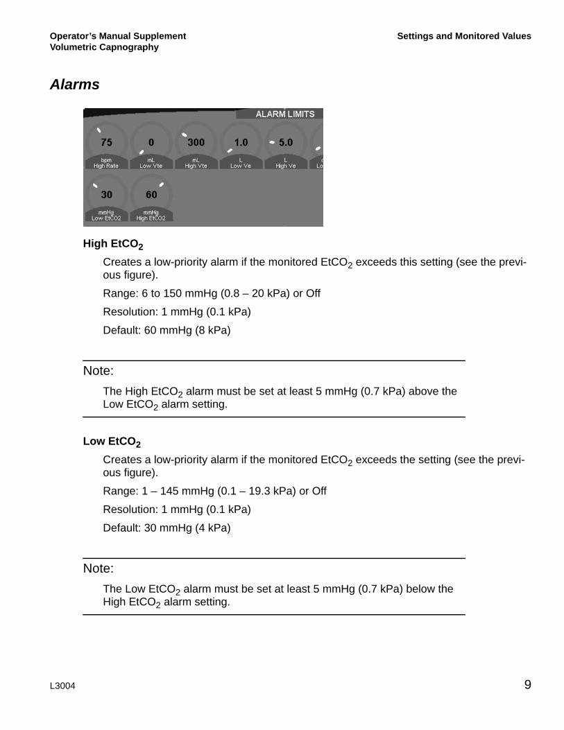
Alarms
High EtCO2 Creates a low-priority alarm if the monitored EtCO2 exceeds this setting (see the previ-ous figure).
Range: 6 to 150 mmHg (0.8 – 20 kPa) or Off
Resolution: 1 mmHg (0.1 kPa)
Default: 60 mmHg (8 kPa)
Note:The High EtCO2 alarm must be set at least 5 mmHg (0.7 kPa) above the Low EtCO2 alarm setting.
Low EtCO2 Creates a low-priority alarm if the monitored EtCO2 exceeds the setting (see the previ-ous figure).
Range: 1 – 145 mmHg (0.1 – 19.3 kPa) or Off
Resolution: 1 mmHg (0.1 kPa)
Default: 30 mmHg (4 kPa)
Note:The Low EtCO2 alarm must be set at least 5 mmHg (0.7 kPa) below the High EtCO2 alarm setting.
L3004 9

Settings and Monitored Values Operator’s Manual SupplementVolumetric Capnography
Maneuvers
Several additional physiologic parameters (Vd/Vt phy, Vd phy, Vd alv, VA, OI and PF) may be calculated by obtaining PaCO2 and PaO2 values at the same time as exhaled CO2 and volume measurements.
1. Immediately before drawing an arterial blood sample, press the Event button and select Arterial Blood Gas.
Volume and CO2 data from the preceding period (set VCO2 Averaging time) are stored.
Note:If you do not create an Arterial Blood Gas event, no data are stored and no calculations can be performed.
2. After analyzing the arterial sample, press the Screens button, select Maneuvers, and then select Capnometry to display the Capnometry Maneuver screen.
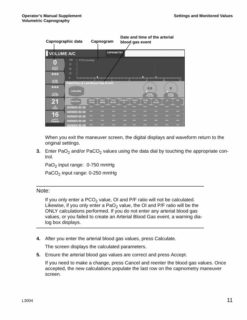
This screen displays data from the last five maneuvers and includes the following:
■ Capnometric data in the digital displays
■ Capnogram
■ Date and time of the arterial blood gas event
WARNING! The patient’s cardio-respiratory status should be stable before per-forming the capnography calculations to ensure the most accurate results.
Event button
10 L3004
Operator’s Manual SupplementVolumetric Capnography
Settings and Monitored Values
When you exit the maneuver screen, the digital displays and waveform return to the original settings.
3. Enter PaO2 and/or PaCO2 values using the data dial by touching the appropriate con-trol.
PaO2 input range: 0-750 mmHg
PaCO2 input range: 0-250 mmHg
Note:If you only enter a PCO2 value, OI and P/F ratio will not be calculated. Likewise, if you only enter a PaO2 value, the OI and P/F ratio will be the ONLY calculations performed. If you do not enter any arterial blood gas values, or you failed to create an Arterial Blood Gas event, a warning dia-log box displays.
4. After you enter the arterial blood gas values, press Calculate.
The screen displays the calculated parameters.
5. Ensure the arterial blood gas values are correct and press Accept.
If you need to make a change, press Cancel and reenter the blood gas values. Once accepted, the new calculations populate the last row on the capnometry maneuver screen.
Capnographic data CapnogramDate and time of the arterial blood gas event
L3004 11

Settings and Monitored Values Operator’s Manual SupplementVolumetric Capnography
Zeroing the CAPNOSTAT 5
The CAPNOSTAT 5 must be zeroed when it is connected to the AVEA and monitoring is started. It must also be zeroed to adjust the sensor to the optical characteristics when you change airway adapter types (single patient use or reusable).
Note:The Capnostat must be at operating temperature to be zeroed. If required, the AVEA will wait up to 120 seconds for the sensor to warm up.
While the zero procedure is in process, all CO2 alarms are turned off. The alarms resume when the procedure is complete.
1. Attach the end of the CO2 sensor cable to the connection on the bottom of the AVEA UIM.
2. Attach the CO2 sensor to the airway adaptor.
3. Access the Capnography Utilities by depressing the Screens soft button, selecting Utility and selecting the Monitoring tab.
WARNING! Failure to correctly zero the CAPNOSTAT 5 may result in incorrect data being displayed. The airway adapter and CO2 sensor must not be attached to the patient circuit during the zero procedure.
WARNING! The airway adapter and CO2 sensor must not be attached to the patient circuit during the zero procedure.
12 L3004
Operator’s Manual SupplementVolumetric Capnography
Settings and Monitored Values
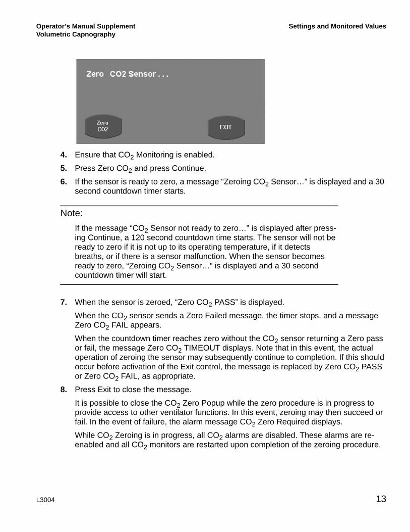
4. Ensure that CO2 Monitoring is enabled.
5. Press Zero CO2 and press Continue.
6. If the sensor is ready to zero, a message “Zeroing CO2 Sensor…” is displayed and a 30 second countdown timer starts.
Note:If the message “CO2 Sensor not ready to zero…” is displayed after press-ing Continue, a 120 second countdown time starts. The sensor will not be ready to zero if it is not up to its operating temperature, if it detects breaths, or if there is a sensor malfunction. When the sensor becomes ready to zero, “Zeroing CO2 Sensor…” is displayed and a 30 second countdown timer will start.
7. When the sensor is zeroed, “Zero CO2 PASS” is displayed.
When the CO2 sensor sends a Zero Failed message, the timer stops, and a message Zero CO2 FAIL appears.
When the countdown timer reaches zero without the CO2 sensor returning a Zero pass or fail, the message Zero CO2 TIMEOUT displays. Note that in this event, the actual operation of zeroing the sensor may subsequently continue to completion. If this should occur before activation of the Exit control, the message is replaced by Zero CO2 PASS or Zero CO2 FAIL, as appropriate.
8. Press Exit to close the message.
It is possible to close the CO2 Zero Popup while the zero procedure is in progress to provide access to other ventilator functions. In this event, zeroing may then succeed or fail. In the event of failure, the alarm message CO2 Zero Required displays.
While CO2 Zeroing is in progress, all CO2 alarms are disabled. These alarms are re-enabled and all CO2 monitors are restarted upon completion of the zeroing procedure.
L3004 13

Settings and Monitored Values Operator’s Manual SupplementVolumetric Capnography
Checking the Accuracy of the CAPNOSTAT 5
The accuracy of the CAPNOSTAT 5 sensor should be compared against a calibration gas every twelve months.
1. Attach the end of the CO2 sensor cable to the connection on the bottom of the AVEA UIM.
2. Attach the CO2 sensor to the airway adaptor.
3. Access the Capnography Utilities by depressing the Screens button, selecting Utility, and the selecting the Monitoring tab.
Screens button
14 L3004

Operator’s Manual SupplementVolumetric Capnography
Settings and Monitored Values
4. Follow the procedure “Zeroing the CAPNOSTAT 5” on page 12. Press Continue when the procedure is complete.
5. Press Calibration Check and then Continue.
6. Set the gas temperature setting to that of the calibration gas (typically room tempera-ture).
7. Attach a regulated, flowing gas mixture of 5% CO2 (± 0.03%) balance nitrogen (N2) to the airway adapter. Set the flow rate of the calibration gas to 2 – 5 liters per minute.
8. Allow 10 seconds for the reading to stabilize. The expected reading is 5% ± 0.26%.
Monitoring tab
L3004 15

Cleaning Operator’s Manual SupplementVolumetric Capnography
Note:While the Calibration Check routine is in process, all CO2 alarms are sus-pended. The alarms resume when the procedure is complete.
Cleaning
SensorTo clean the outside of the sensor and cable:
■ Use a cloth dampened with 70% isopropyl alcohol, 10% bleach solution, disinfectant spray cleaner such as Steris Coverage® SprayHB, ammonia, or mild soap.
■ Wipe surfaces with a clean, water-dampened cloth before use. Ensure that the sensor is clean and dry before use.
Airway Adaptors
Reusable AdaptorsClean reusable adaptors by rinsing them in warm soapy water followed by soaking them in a liquid disinfectant such as 70% isopropyl alcohol, 10% bleach solution, 2.4% glutaraldehyde solution such as Cidex®, Steris System1® or ammonia. Rinse with sterile water and dry before use.
The adapter may also be disinfected using one of the following methods:
■ Steam autoclave the adaptor (adult adaptor only).
■ Immerse and soak the adaptor in 2.4% glutaraldehyde solution such as Cidex for 10 hours.
■ Immerse and soak the adaptor in 0.26% paracetic acid solution such as Perasafe® for 10 minutes.
■ Use Cidex OPA (follow manufacturer’s instructions for use).
Before reusing the adaptor, ensure the windows are dry and free of residue, and that the adaptor has not been damaged during the cleaning/disinfecting process.
Disposable AdaptorsTreat all single-patient use adaptors in accordance with institutional protocol for single-patient use items.
16 L3004

Operator’s Manual Supplement Volumetric Capnography
APPENDIX
Troubleshooting
Error Message Corrective Action
CO2 Communication Error Medium-priority alarm. Ensure the sensor is properly plugged in. Reinsert the sensor if necessary. If the error persists, call technical support.
CO2 Sensor Faulty Medium-priority alarm. Ensure the sensor is properly plugged in. Reinsert the sensor if necessary. If the error persists, call technical support.
CO2 Sensor Over Temp Medium-priority alarm. Ensure the sensor is not exposed to extreme temperatures, such as temperatures produced by lamps. If the error persists, call technical support.
CO2 Zero Required Medium-priority alarm. Check airway adapter and clean if needed. If the error persists, perform an adapter zero procedure.
CO2 Out of Range Medium-priority alarm when the CO2 measured by the sensor exceeds 150 mmHg (20.0 kPa). If the error persists, perform a zero procedure.
Check CO2 Airway Adaptor Medium-priority alarm. Check the airway adapter and clean it if needed. If the error persists, perform an adapter zero procedure.
Invalid EtCO2 Medium-priority alarm. No breaths are being detected by the CAPNOSTAT 5. Ensure spontaneous or mechanical breaths are being delivered to the patient. Confirm that the airway adapter is placed in the airway between any connector(s) and the circuit wye and that the sensor is firmly attached to the adaptor.
L3004 17
Appendix Operator’s Manual SupplementVolumetric Capnography
Calculations
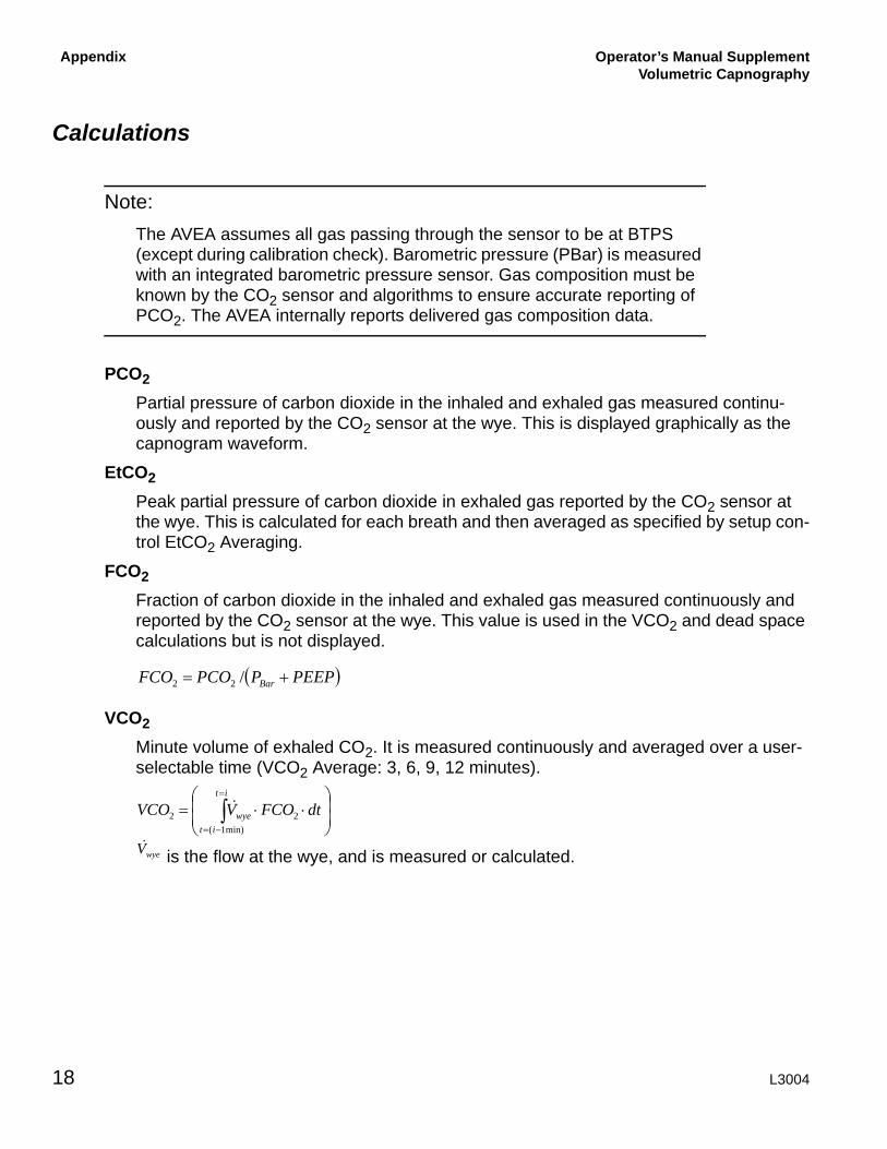
Note:The AVEA assumes all gas passing through the sensor to be at BTPS (except during calibration check). Barometric pressure (PBar) is measured with an integrated barometric pressure sensor. Gas composition must be known by the CO2 sensor and algorithms to ensure accurate reporting of PCO2. The AVEA internally reports delivered gas composition data.
PCO2
Partial pressure of carbon dioxide in the inhaled and exhaled gas measured continu-ously and reported by the CO2 sensor at the wye. This is displayed graphically as the capnogram waveform.
EtCO2
Peak partial pressure of carbon dioxide in exhaled gas reported by the CO2 sensor at the wye. This is calculated for each breath and then averaged as specified by setup con-trol EtCO2 Averaging.
FCO2
Fraction of carbon dioxide in the inhaled and exhaled gas measured continuously and reported by the CO2 sensor at the wye. This value is used in the VCO2 and dead space calculations but is not displayed.
VCO2
Minute volume of exhaled CO2. It is measured continuously and averaged over a user-selectable time (VCO2 Average: 3, 6, 9, 12 minutes).
is the flow at the wye, and is measured or calculated.
( )PEEPPPCOFCO Bar += /22
⎟⎟⎠
⎞⎜⎜⎝
⎛⋅⋅= ∫
=
−=
it
itwye dtFCOVVCO
min)1(22
&
wyeV&
18 L3004

Operator’s Manual SupplementVolumetric Capnography
Appendix
VtCO2
Tidal volume of exhaled CO2. It is measured over the period of each breath and aver-aged over a user-selectable time (VCO2 Average: 3, 6, 9, 12 minutes).
FeCO2
Percentage of carbon dioxide in the exhaled gas reported by the CO2 sensor at the wye. This value is used in the dead space calculations but is not displayed.
PeCO2
Mean exhaled partial pressure of carbon dioxide in the exhaled gas reported by the CO2 sensor at the wye. This value is used in the dead space calculations but is not dis-played.
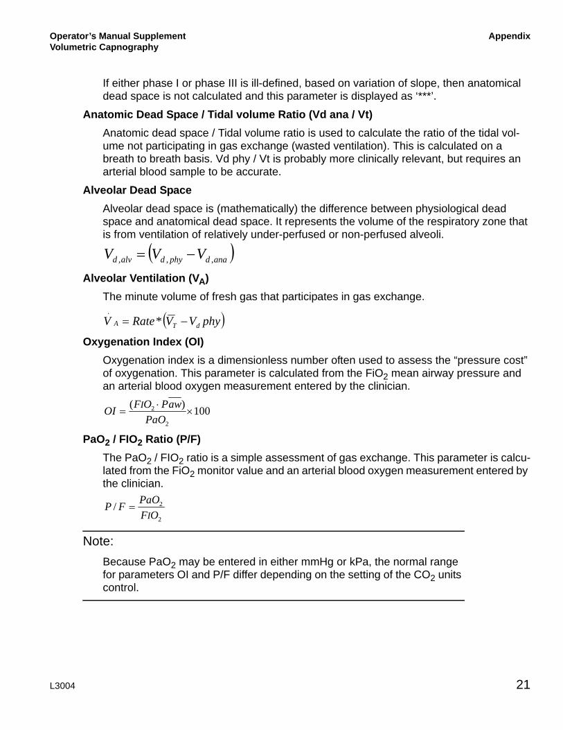
Physiologic Dead Space (Vd phy)Comprises anatomic dead space (see below) as well as the volume of the respiratory zone (respiratory bronchioles, alveolar ducts and alveoli) not participating in gas exchange. The classic Bohr-Enghoff1 equation is used to calculate physiologic dead space. This method uses arterial CO2 (PaCO2) as an estimator for alveolar CO2 (PACO2).
Physiologic Dead Space / Tidal volume ratio (Vd phy / Vt)Used to calculate the ratio of the tidal volume not participating in gas exchange (wasted ventilation).
1. Enghoff H: Volumen inefficax: Bemerkungen zur Frage des schadlichen Raumes. Upsalla Lakareforen Forhandl, 1938; 44:191-218.
⎟⎟
⎠
⎞
⎜⎜
⎝
⎛⋅⋅= ∫
exp
22T
wyet dtFCOVCOV &
eVVCOFeCO /22 =
( )PEEPPFeCOPeCO Bar +×= 22
⎟⎟⎠
⎞⎜⎜⎝
⎛−⋅=
2
21aCO
eCOtd P
PVphyV
⎟⎟⎠
⎞⎜⎜⎝
⎛−=
2
21aCO
eCO
t
d
PPphy
VV
L3004 19

Appendix Operator’s Manual SupplementVolumetric Capnography
Anatomic Dead Space (Vd ana)Total volume of the conducting airways from the nose to the level of the terminal bron-chioles (areas that do not participate in gas exchange). Anatomic dead space also includes any mechanical dead spaces added to the ventilator circuit between the CO2 sensor and the patient.
At end of each exhalation, calculation is carried out equivalent to the graphical method defined by Fowler 1. The fraction of CO2 in the exhaled gas is considered as a function of volume exhaled.
Using Fowler’s nomenclature, phase I is the initial exhaled volume with constant FCO2. FCO2 during phase I is calculated as FI. Phase III is the linear part of the capnogram associated with exhalation of gas from the lung gas exchange units. This is calculated using linear regression over that part of the capnogram representing 30 to 70% of exhaled CO2. The slope of phase III is calculated as m, with offset at the FCO2 axis FO.
Shaded areas x and y are equal.
The volume above the capnogram and below the regression line through phase III is calculated as A.
Anatomical dead space is defined as that point on the volume axis at which the volumes shaded below and above the curve are equal. This is calculated using an algebraic method2
This parameter is calculated for each breath and then averaged over the same period as VCO2.
1. Fowler W S, Lung Function Studies II: The Respiratory Dead Space, Am J Physiol 1948; 154: 405-4162. Heller H, Könen-Bergmann M, Schuster K D, An Algebraic Solution to Dead Space Determination According to Fowler’s Graphical Method, Comput Biomed Res 1999; 32: 161-167
( ) ( ) ⎟⎟
⎠
⎞
⎜⎜
⎝
⎛
⋅+−+−
⋅=
mAFIFOFIFO
AV anad2
22,
20 L3004
Operator’s Manual SupplementVolumetric Capnography
Appendix
If either phase I or phase III is ill-defined, based on variation of slope, then anatomical dead space is not calculated and this parameter is displayed as ‘***’.
Anatomic Dead Space / Tidal volume Ratio (Vd ana / Vt)Anatomic dead space / Tidal volume ratio is used to calculate the ratio of the tidal vol-ume not participating in gas exchange (wasted ventilation). This is calculated on a breath to breath basis. Vd phy / Vt is probably more clinically relevant, but requires an arterial blood sample to be accurate.
Alveolar Dead SpaceAlveolar dead space is (mathematically) the difference between physiological dead space and anatomical dead space. It represents the volume of the respiratory zone that is from ventilation of relatively under-perfused or non-perfused alveoli.
Alveolar Ventilation (VA)The minute volume of fresh gas that participates in gas exchange.
Oxygenation Index (OI)Oxygenation index is a dimensionless number often used to assess the “pressure cost” of oxygenation. This parameter is calculated from the FiO2 mean airway pressure and an arterial blood oxygen measurement entered by the clinician.
PaO2 / FIO2 Ratio (P/F)The PaO2 / FIO2 ratio is a simple assessment of gas exchange. This parameter is calcu-lated from the FiO2 monitor value and an arterial blood oxygen measurement entered by the clinician.
Note:Because PaO2 may be entered in either mmHg or kPa, the normal range for parameters OI and P/F differ depending on the setting of the CO2 units control.
( )anadphydalvd VVV ,,, −=
( )phyVVRateV dTA −= *.
100)(
2
2 ×⋅
=PaO
awPOFOI I
2
2/OF
PaOFPI
=
L3004 21

Appendix Operator’s Manual SupplementVolumetric Capnography
SpecificationsSensorsSensor Type Mainstream, non-dispersive infrared single-beam optics, dual
wavelengths. No moving parts
Sensor Physical Characteristics
Weight: 25 g (78 g with standard cable and connectors)Size: 33 mm x 43 mm x 23 mm. Cable length: 3 m
Sensor Compatibility The VIASYS Capnostat 5 is interchangeable between VIASYS equipment only.
CO2 Measurement
CO2 Measurement range 0 – 150 mmHg (0 – 20 kPa)
CO2 Measurement Accuracy
± 2 mmHg for 0-40 mmHg± 5% of reading for 41-70 mmHg± 8% of reading for 71-100 mmHg± 10% of reading for 101-150 mmHg
CO2 Resolution 1 mmHg
CO2 Stability < 0.8 mmHg over four hours
Gas Composition Compensation
Oxygen and Helium gas composition. Automatic compensation
Airway AdaptorsAdult/Pediatric Single Patient Use
■ For use with endotracheal tube greater than 4mm ID■ Dead space: 5 mL■ Weight: 7.7 g■ Color: Clear
Infant /PediatricSingle Patient Use
■ For use with endotracheal tube less than or equal to 4mm ID■ Dead space: < 1 mL■ Weight: 9.1 g■ Color: Purple
Adult/PediatricReusable
■ For use with endotracheal tube greater than 4mm ID■ Dead space: 5 mL■ Weight: 12 g■ Color: Black
Infant /PediatricReusable
■ For use with endotracheal tube less than or equal to 4mm ID■ Dead space: < 1 mL■ Weight: 14.9 g■ Color: Red
All components are Latex free
22 L3004