operator’s manual pump pts 4v ptk 4 - wacker...
TRANSCRIPT
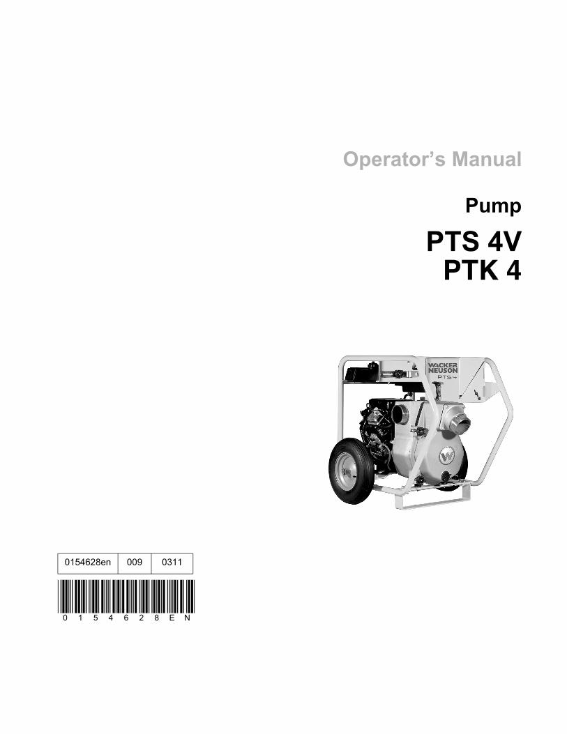
0154628en 009 0311
0 1 5 4 6 2 8 E N
Operator’s Manual
Pump
PTS 4VPTK 4
Copyright notice
© Copyright 2010 by Wacker Neuson Corporation.All rights, including copying and distribution rights, are reserved.This publication may be photocopied by the original purchaser of the machine. Any other type of reproduction is prohibited without express written permission from Wacker Neuson Corporation.Any type of reproduction or distribution not authorized by Wacker Neuson Corporation represents an infringement of valid copyrights. Violators will be prosecuted.
Trademarks All trademarks referenced in this manual are the property of their respective owners.
Manufacturer Wacker Neuson CorporationN92W15000 Anthony AvenueMenomonee Falls, WI 53051 U.S.A.Tel: (262) 255-0500 · Fax: (262) 255-0550 · Tel: (800) 770-0957www.wackerneuson.com
Original instructions
This Operator’s Manual presents the original instructions. The original language of this Operator’s Manual is American English.

PTS 4V / PTK 4 Foreword
ForewordMachines covered in this manualMachine documentation
Keep a copy of the Operator’s Manual with the machine at all times. Use the separate Parts Book supplied with the machine to order replacement parts. Refer to the separate Repair Manual for detailed instructions on servicing and repairing the machine.If you are missing any of these documents, please contact Wacker Neuson Corporation to order a replacement or visit www.wackerneuson.com. When ordering parts or requesting service information, be prepared to provide the machine model number, item number, revision number, and serial number.
Expectations for information in this manual
This manual provides information and procedures to safely operate and maintain the above Wacker Neuson model(s). For your own safety and to reduce the risk of injury, carefully read, understand, and observe all instructions described in this manual. Wacker Neuson Corporation expressly reserves the right to make technical modifications, even without notice, which improve the performance or safety standards of its machines.The information contained in this manual is based on machines manufactured up until the time of publication. Wacker Neuson Corporation reserves the right to change any portion of this information without notice.
CALIFORNIA Proposition 65 Warning
Engine exhaust, some of its constituents, and certain vehicle components, contain or emit chemicals known to the State of California to cause cancer and birth defects or other reproductive harm.
Laws pertaining to spark arresters
NOTICE: State Health Safety Codes and Public Resources Codes specify that in certain locations spark arresters be used on internal combustion engines that use hydrocarbon fuels. A spark arrester is a device designed to prevent accidental dis-charge of sparks or flames from the engine exhaust. Spark arresters are qualified and rated by the United States Forest Service for this purpose. In order to comply with local laws regarding spark arresters, consult the engine distributor or the local Health and Safety Administrator.
Manufacturer’s approval
This manual contains references to approved parts, attachments, and modifica-tions. The following definitions apply:
Approved parts or attachments are those either manufactured or provided by Wacker Neuson. Approved modifications are those performed by an authorized Wacker Neuson service center according to written instructions published by Wacker Neuson.
Machine Item NumberPTS 4V 0007683, 0007691PTK 4 0007692
wc_tx001343gb.fm 3

Foreword PTS 4V / PTK 4
Unapproved parts, attachments, and modifications are those that do not meet the approved criteria.Unapproved parts, attachments, or modifications may have the following conse-quences:
Serious injury hazards to the operator and persons in the work areaPermanent damage to the machine which will not be covered under warranty
Contact your Wacker Neuson dealer immediately if you have questions about approved or unapproved parts, attachments, or modifications.
4 wc_tx001343gb.fm
PTS 4V / PTK 4 Table of Contents
1 Safety Information 71.1 Operation / Intended Use ..................................................................... 81.2 Operating Safety ................................................................................ 101.3 Operator Safety while using Internal Combustion Engines ................ 111.4 Service Safety .................................................................................... 13
2 Labels 14
2.1 Label Locations ............................................................................... 142.2 Safety Labels ...................................................................................... 15
3 Lifting and Transporting 18
4 Operation 19
4.1 Preparing the Machine for First Use ................................................... 194.2 Recommended Fuel ........................................................................... 194.3 Before Starting ................................................................................... 194.4 To Start ............................................................................................... 214.5 To Stop ............................................................................................... 224.6 Operation ............................................................................................ 224.7 Pump Wrench ..................................................................................... 224.8 Accessories ........................................................................................ 234.9 Hoses and Clamps ............................................................................. 234.10 Emergency Shutdown Procedure ....................................................... 24
5 Maintenance 25
5.1 Periodic Maintenance Schedule ......................................................... 255.2 Engine Lubrication .............................................................................. 265.3 Changing Oil Filter .............................................................................. 275.4 Air Cleaner ......................................................................................... 285.5 Spark Plug .......................................................................................... 295.6 Fuel Filter ........................................................................................... 305.7 Carburetor Adjustment ....................................................................... 30
wc_bo0154628en_009TOC.fm 5

Table of Contents PTS 4V / PTK 4
5.8 Changing Mechanical Seal Coolant ....................................................315.9 Adjusting Impeller Clearance ..............................................................325.10 Cleaning Pump ....................................................................................335.11 Storage ................................................................................................345.12 Troubleshooting ...................................................................................356 Technical Data 36
6.1 Engine .................................................................................................366.2 Pump ...................................................................................................376.3 Sound Measurements .........................................................................376.4 Dimensions ..........................................................................................38
6 wc_bo0154628en_009TOC.fm

PTS 4V / PTK 4 Safety Information
1 Safety InformationThis manual contains DANGER, WARNING, CAUTION, NOTICE, and NOTE signal words which must be followed to reduce the possibility of personal injury, damage to the equipment, or improper service.
NOTICE: Used without the safety alert symbol, NOTICE indicates a situation which, if not avoided, could result in property damage.
Note: A Note contains additional information important to a procedure.
This is the safety alert symbol. It is used to alert you to potential personal hazards.Obey all safety messages that follow this symbol.
DANGERDANGER indicates a hazardous situation which, if not avoided, will result in death or serious injury.
To avoid death or serious injury from this type of hazard, obey all safety mes-sages that follow this signal word.
WARNINGWARNING indicates a hazardous situation which, if not avoided, could result in death or serious injury.
To avoid possible death or serious injury from this type of hazard, obey all safety messages that follow this signal word.
CAUTIONCAUTION indicates a hazardous situation which, if not avoided, could result in minor or moderate injury.
To avoid possible minor or moderate injury from this type of hazard, obey all safety messages that follow this signal word.
wc_si000130gb.fm 7
Safety Information PTS 4V / PTK 4
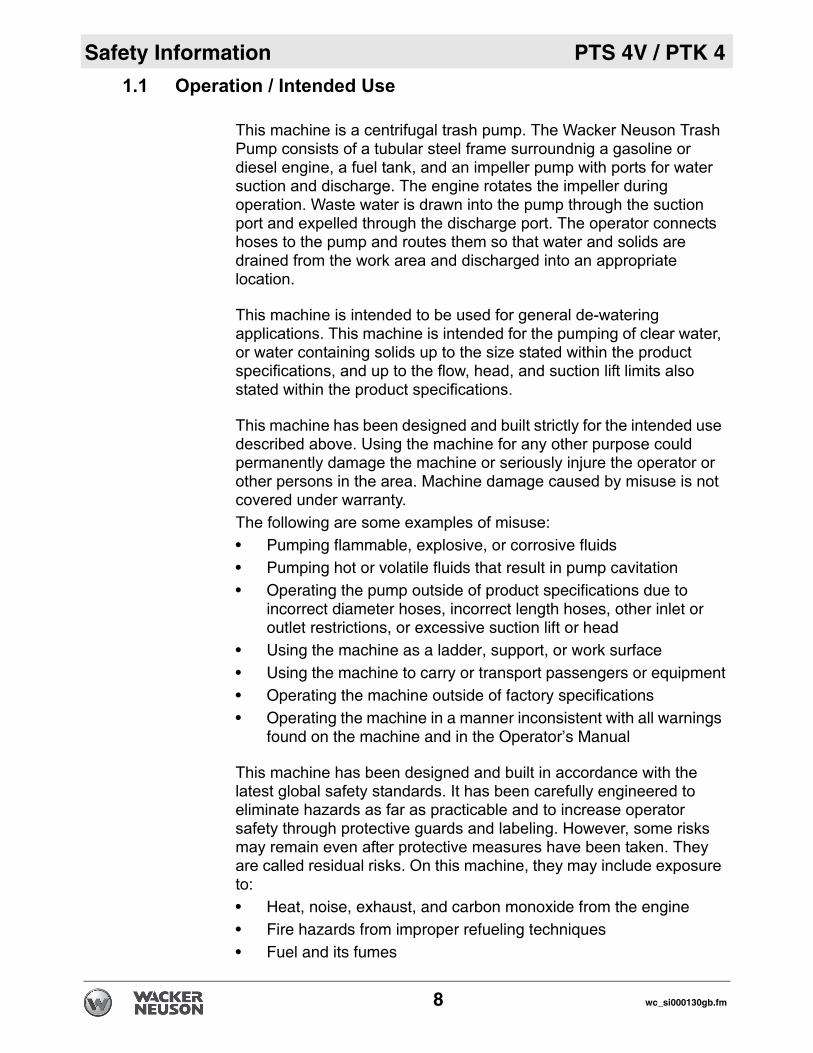
1.1 Operation / Intended UseThis machine is a centrifugal trash pump. The Wacker Neuson Trash Pump consists of a tubular steel frame surroundnig a gasoline or diesel engine, a fuel tank, and an impeller pump with ports for water suction and discharge. The engine rotates the impeller during operation. Waste water is drawn into the pump through the suction port and expelled through the discharge port. The operator connects hoses to the pump and routes them so that water and solids are drained from the work area and discharged into an appropriate location.
This machine is intended to be used for general de-watering applications. This machine is intended for the pumping of clear water, or water containing solids up to the size stated within the product specifications, and up to the flow, head, and suction lift limits also stated within the product specifications.
This machine has been designed and built strictly for the intended use described above. Using the machine for any other purpose could permanently damage the machine or seriously injure the operator or other persons in the area. Machine damage caused by misuse is not covered under warranty. The following are some examples of misuse:• Pumping flammable, explosive, or corrosive fluids• Pumping hot or volatile fluids that result in pump cavitation• Operating the pump outside of product specifications due to
incorrect diameter hoses, incorrect length hoses, other inlet or outlet restrictions, or excessive suction lift or head
• Using the machine as a ladder, support, or work surface• Using the machine to carry or transport passengers or equipment• Operating the machine outside of factory specifications• Operating the machine in a manner inconsistent with all warnings
found on the machine and in the Operator’s Manual
This machine has been designed and built in accordance with the latest global safety standards. It has been carefully engineered to eliminate hazards as far as practicable and to increase operator safety through protective guards and labeling. However, some risks may remain even after protective measures have been taken. They are called residual risks. On this machine, they may include exposure to:• Heat, noise, exhaust, and carbon monoxide from the engine• Fire hazards from improper refueling techniques• Fuel and its fumes
8 wc_si000130gb.fm

PTS 4V / PTK 4 Safety Information
• Personal injury from improper lifting techniques• Projectile hazard from discharge • Crushing hazards from a tipping or falling pumpTo protect yourself and others, make sure you thoroughly read and understand the safety information presented in this manual before operating the machine.wc_si000130gb.fm 9
Safety Information PTS 4V / PTK 4
1.2 Operating SafetyFamiliarity and proper training are required for the safe operation of themachine. Machines operated improperly or by untrained personnelcan be hazardous. Read the operating instructions contained in thismanual and the engine manual, and familiarize yourself with thelocation and proper use of all controls. Inexperienced operators shouldreceive instruction from someone familiar with the machine beforebeing allowed to operate it.
Operator qualificationsOnly trained personnel are permitted to start, operate, and shut down the machine. They also must meet the following qualifications:• have received instruction on how to properly use the machine• are familiar with required safety devices
The machine must not be accessed or operated by:• children• people impaired by alcohol or drugs
Personal Protective Equipment (PPE)Wear the following Personal Protective Equipment (PPE) while operating this machine:• Close-fitting work clothes that do not hinder movement• Safety glasses with side shields• Hearing protection• Safety-toed footwear
1.2.1 Do not allow anyone to operate this equipment without proper training.People operating this equipment must be familiar with the risks andhazards associated with it.
1.2.2 Do not use accessories or attachments that are not recommended byWacker Neuson. Damage to equipment and injury to the user may result.
1.2.3 Do not touch the engine or muffler while the engine is on or immediatelyafter it has been turned off. These areas get hot and may cause burns.
1.2.4 Do not pump volatile, flammable, or low flash point fluids. These fluidscould ignite or explode.
1.2.5 Do not pump corrosive chemicals or water containing toxic substances.These fluids could create serious health and environmental hazards.Contact local authorities for assistance.
1.2.6 Do not open the priming plug when the pump is hot. Do not loosen orremove inlet or discharge hose fittings when the pump is hot. Hot waterinside could be pressurized much like the radiator on an automobile. Allowthe pump to cool to the touch before loosening the plug and beforeloosening or removing the inlet or discharge hose fittings.
WARNING
10 wc_si000130gb.fm

PTS 4V / PTK 4 Safety Information
1.2.7 Do not open pump housing cover while pump is operating, or start pumpwith the cover off. The rotating impeller inside the pump can cut or severobjects caught in it.
1.2.8 Do not block or restrict flow from inlet line or discharge line. Remove kinksfrom discharge line before starting pump. Operation with a blocked inletline or discharge line can cause water inside pump to overheat.
1.2.9 Be sure operator is familiar with proper safety precautions and operationtechniques before using machine.
1.2.10 Read, understand, and follow procedures in the Operator’s Manual beforeattempting to operate the machine.
1.2.11 Be sure the machine is on a firm, level surface and will not tip, roll, slide,or fall while operating.
1.2.12 Close fuel valve on engines equipped with one when machine is not beingoperated.
1.2.13 Store the machine properly when it is not being used. The machine shouldbe stored in a clean, dry location out of the reach of children.
1.2.14 Wear hearing protection when operating equipment.1.2.15 Do not pump fluid into an inappropriate location.1.2.16 Do not place hoses where they may become a tripping hazard.1.2.17 Do not operate the pump without the strainer or with an incorrect strainer.1.2.18 Do not operate the machine with unapproved accessories or attachments.1.2.19 Do not transport the machine while it is running.
1.3 Operator Safety while using Internal Combustion Engines
WARNINGInternal combustion engines present special hazards during operation and fueling. Failure to follow the warnings and safety standards could result in severe injury or death.
Read and follow the warning instructions in the engine owner’s manual and the safety guidelines below.
DANGERAsphyxiation hazard. Using a pump indoors CAN KILL YOU IN MINUTES. Pump exhaust contains carbon monoxide. This is a poison you cannot see or smell.
NEVER use this pump inside a home or garage, EVEN IF doors and windows are open. Only use OUTSIDE and far away from windows, doors, and vents.NEVER use a pump inside an enclosed area, such as a tunnel or a trench, unless adequate ventilation is provided through such items as exhaust fans or hoses.
wc_si000130gb.fm 11

Safety Information PTS 4V / PTK 4
Operating safetyWhen operating the pump:• Keep the area around exhaust pipe free of flammable materials.• Check the fuel lines and the fuel tank for leaks and cracks before
starting the engine. When operating the pump:• Do not smoke while operating the machine.• Do not run the machine if fuel leaks are present or the fuel lines
are loose.• Do not run the engine near sparks or open flames.• Do not touch the engine or muffler while the engine is running or
immediately after it has been turned off.• Do not operate a machine when its fuel cap is loose or missing.• Do not start the engine if fuel has spilled or a fuel odor is present.
Move the machine away from the spill and wipe the machine dry before starting.
Refueling safetyWhen refueling the engine:• Clean up any spilled fuel immediately.• Refill the fuel tank in a well-ventilated area.• Replace the fuel tank cap after refueling.When refueling the engine:• Do not smoke.• Do not refuel a hot or running engine.• Do not refuel the engine near sparks or open flames.• Do not refuel if the machine is positioned in a truck fitted with a
plastic bed liner. Static electricity can ignite the fuel or fuel vapors.
12 wc_si000130gb.fm

PTS 4V / PTK 4 Safety Information
1.4 Service SafetyA poorly maintained machine can become a safety hazard! In orderfor the machine to operate safely and properly over a long period oftime, periodic maintenance and occasional repairs are necessary.
Personal Protective Equipment (PPE)Wear the following Personal Protective Equipment (PPE) while servicing or maintaining this machine:• Close-fitting work clothes that do not hinder movement• Safety glasses with side shields• Hearing protection• Safety-toed footwearIn addition, before servicing or maintaining the machine:• Tie back long hair.• Remove all jewelry (including rings).
1.4.1 Do not attempt to clean or service the machine while it is running. Rotatingparts can cause severe injury.
1.4.2 Do not crank a flooded engine with the spark plug removed on gasoline-powered engines. Fuel trapped in the cylinder will squirt out the spark plugopening.
1.4.3 Do not test for spark on gasoline-powered engines if the engine is floodedor the smell of gasoline is present. A stray spark could ignite the fumes.
1.4.4 Do not use gasoline or other types of fuels or flammable solvents to cleanparts, especially in enclosed areas. Fumes from fuels and solvents canbecome explosive.
1.4.5 Always operate machine with all safety devices and guards in place and inworking order. Do not modify or defeat safety devices. Do not operatemachine if any safety devices or guards are missing or inoperative.
1.4.6 Keep the area around the muffler free of debris such as leaves, paper,cartons, etc. A hot muffler could ignite the debris and start a fire.
1.4.7 When replacement parts are required for this machine, use only WackerNeuson replacement parts or those parts equivalent to the original in alltypes of specifications, such as physical dimensions, type, strength, andmaterial.
1.4.8 Disconnect the spark plug on machines equipped with gasoline engines,before servicing, to avoid accidental start-up.
1.4.9 Keep the machine clean and labels legible. Replace all missing and hard-to-read labels. Labels provide important operating instructions and warn ofdangers and hazards.
1.4.10 Handle impeller carefully. The impeller can develop sharp edges whichcan cut.
1.4.11 Do not tip the machine for cleaning or for any other reason.
WARNING
wc_si000130gb.fm 13

Labels PTS 4V / PTK 4
2 Labels2.1 Label Locations
wc_gr001479
H
A
F
D
DC
G
B
C
E
J
K
14 wc_si000397gb.fm

PTS 4V / PTK 4 Labels
2.2 Safety LabelsWacker Neuson machines use international pictorial labels whereneeded. These labels are described below.
Label MeaningA DANGER!
Asphyxiation hazard.Engines emit carbon monoxide. Do not run the machine indoors or in an enclosed area.NEVER use inside a home or garage, EVEN IF doors and windows are open.Only use OUTSIDE and far away from win-dows, doors, and vents.Read the Operator’s Manual.No sparks, flames, or burning objects near the machine. Stop the engine before refueling.
B WARNING! Hot surface!
C CAUTION!Read and understand the supplied Oper-ator’s Manual before operating this machine. Failure to do so increases the risk of injury to yourself and others.
wc_si000397gb.fm 15
Labels PTS 4V / PTK 4
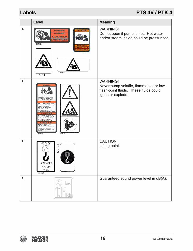
D WARNING! Do not open if pump is hot. Hot water and/or steam inside could be pressurized.
E WARNING! Never pump volatile, flammable, or low-flash-point fluids. These fluids could ignite or explode.
F CAUTION Lifting point.
G Guaranteed sound power level in dB(A).
Label Meaning
16 wc_si000397gb.fm
PTS 4V / PTK 4 Labels
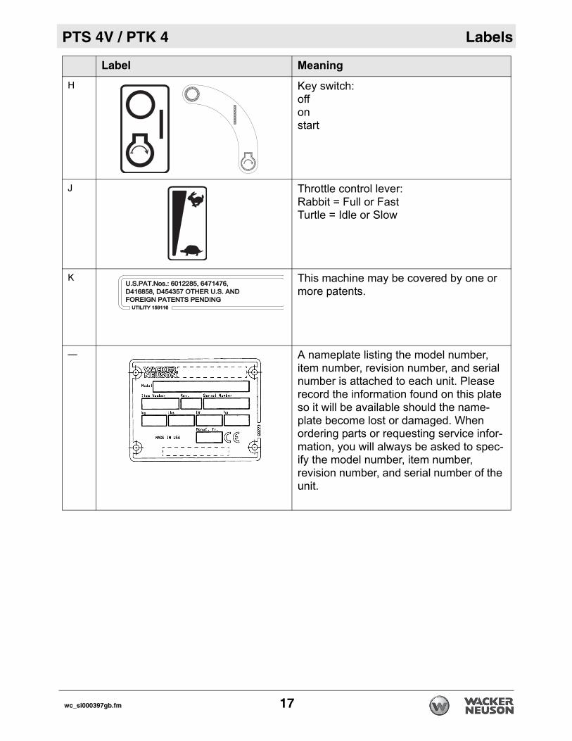
H Key switch:offonstart
J Throttle control lever:Rabbit = Full or FastTurtle = Idle or Slow
K This machine may be covered by one or more patents.
— A nameplate listing the model number, item number, revision number, and serial number is attached to each unit. Please record the information found on this plate so it will be available should the name-plate become lost or damaged. When ordering parts or requesting service infor-mation, you will always be asked to spec-ify the model number, item number, revision number, and serial number of the unit.
Label Meaning
UTILITY 159116UTILITY 159116
U.S.PAT.Nos.: 6012285, 6471476, U.S.PAT.Nos.: 6012285, 6471476, D416858, D454357 OTHER U.S. AND D416858, D454357 OTHER U.S. AND FOREIGN PATENTS PENDINGFOREIGN PATENTS PENDING
wc_si000397gb.fm 17
Lifting and Transporting PTS 4V / PTK 4
18 wc_tx001348gb.fm
3 Lifting and Transporting
Lifting the machine• Do not attempt to lift the pump unassisted. Use appropriate lifting
equipment such as slings, chains, hooks, ramps, or jacks.
• Make sure lifting equipment is attached securely and has enough weight-bearing capacity to lift or hold the pump safely.
• Remain aware of the location of other people nearby when lifting the pump.
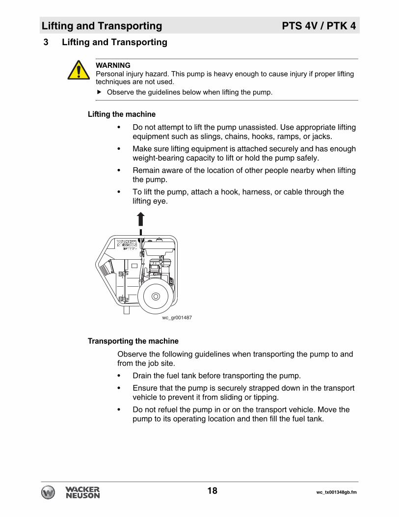
• To lift the pump, attach a hook, harness, or cable through the lifting eye.
Transporting the machineObserve the following guidelines when transporting the pump to and from the job site.• Drain the fuel tank before transporting the pump.
• Ensure that the pump is securely strapped down in the transport vehicle to prevent it from sliding or tipping.
• Do not refuel the pump in or on the transport vehicle. Move the pump to its operating location and then fill the fuel tank.
WARNINGPersonal injury hazard. This pump is heavy enough to cause injury if proper lifting techniques are not used.
Observe the guidelines below when lifting the pump.
wc_gr001487

PTS 4V / PTK 4 Operation
4 Operation4.1 Preparing the Machine for First Use
Preparing for first useTo prepare your machine for first use:
4.1.1 Make sure all loose packaging materials have been removed from the machine.
4.1.2 Check the machine and its components for damage. If there is visible damage, do not operate the machine! Contact your Wacker Neuson dealer immediately for assistance.
4.1.3 Take inventory of all items included with the machine and verify that all loose components and fasteners are accounted for.
4.1.4 Attach component parts not already attached.4.1.5 Add fluids as needed and applicable, including fuel, engine oil, and
battery acid.4.1.6 Move the machine to its operating location.
4.2 Recommended Fuel
The engine requires regular grade unleaded gasoline. Use only fresh,clean gasoline. Gasoline containing water or dirt will damage fuelsystem. Consult engine owner’s manual for complete fuelspecifications.
4.3 Before Starting
See Graphic: wc_gr0000134.3.1 Read safety instructions at the beginning of this Operator’s Manual.4.3.2 Place pump as near to water as possible, on a firm, flat, level surface. 4.3.3 To prime pump, remove prime plug (a) and fill pump housing with
water. If the pump housing is not filled with water before starting, it willnot begin pumping. Do not open priming plug, discharge plug, or loosen hose fittings ifpump is hot! Water or vapor inside pump may be under pressure.
WARNING
wc_tx000339gb.fm 19
Operation PTS 4V / PTK 4
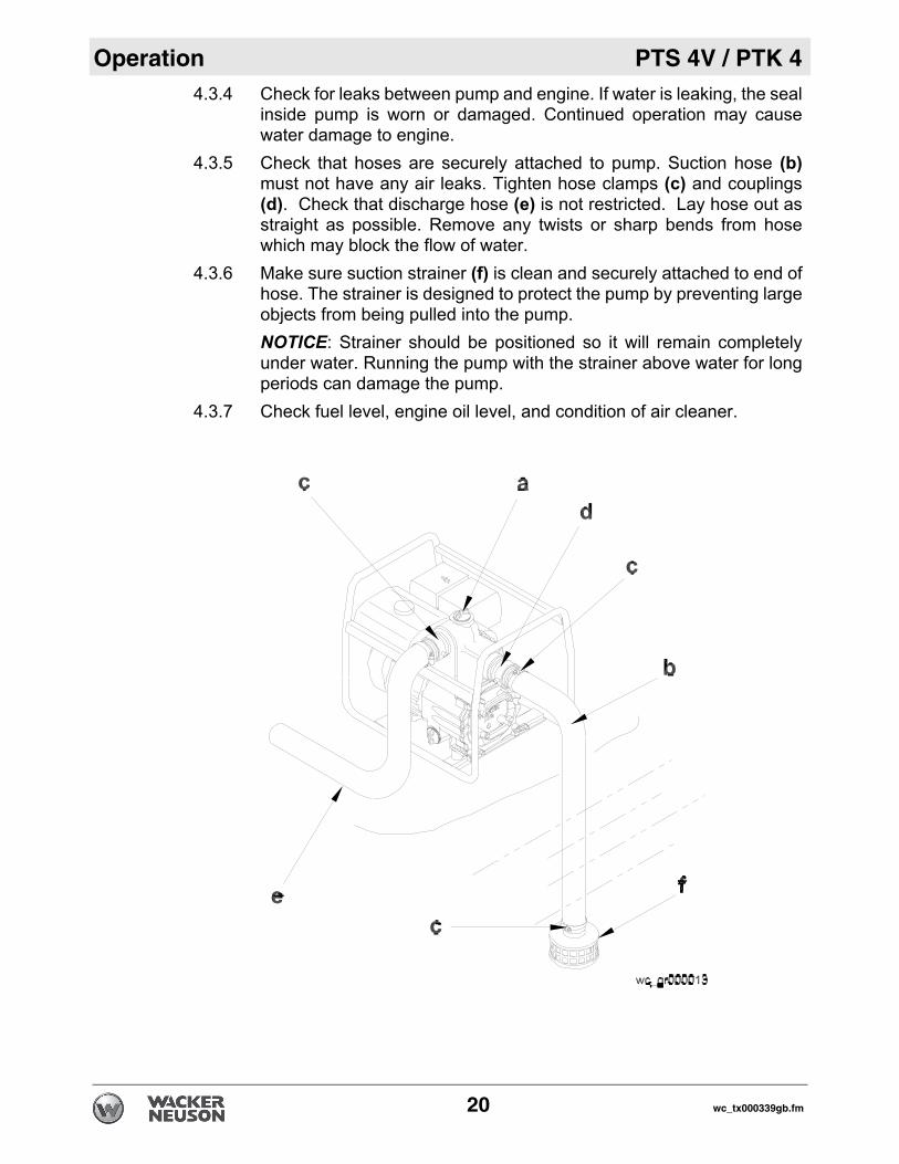
4.3.4 Check for leaks between pump and engine. If water is leaking, the sealinside pump is worn or damaged. Continued operation may causewater damage to engine.
4.3.5 Check that hoses are securely attached to pump. Suction hose (b)must not have any air leaks. Tighten hose clamps (c) and couplings(d). Check that discharge hose (e) is not restricted. Lay hose out asstraight as possible. Remove any twists or sharp bends from hosewhich may block the flow of water.
4.3.6 Make sure suction strainer (f) is clean and securely attached to end ofhose. The strainer is designed to protect the pump by preventing largeobjects from being pulled into the pump.NOTICE: Strainer should be positioned so it will remain completelyunder water. Running the pump with the strainer above water for longperiods can damage the pump.
4.3.7 Check fuel level, engine oil level, and condition of air cleaner.
20 wc_tx000339gb.fm

PTS 4V / PTK 4 Operation
4.4 To StartSee Graphic: wc_gr001480Follow the instructions below and read starting and stoppinginstuctions found in the engine owner’s manual.
4.4.1 Open the fuel valve (b1).4.4.2 If the engine is cold, pull out the choke control (a1). If the engine is hot,
push in the choke control (a2).4.4.3 Move the throttle control to the fast position (c1). 4.4.4 Turn the key switch to the start position (d3) and hold it until the engine
starts.NOTICE: Do not crank engine longer than 15 seconds at a time.Extended cranking can damage the starter motor.
4.4.5 To start the engine using manual start: • Turn the key switch to the run position (d2). • Rapidly pull the starter rope (e) to start the engine.
• Leave key in run position (d2) while engine is running.
Note: The engine is equipped with a low oil protection system, whichdoes not allow the engine to start if the oil level is low. This device willnot protect the engine if a low oil level occurs while running. The switchopens on a pressure rise of 4 psi ±1.5 psi.
4.4.6 Push the choke in as the engine warms (a2).4.4.7 Keep the engine throttle in the fast position while operating pump.
wc_gr001480
d1d2
d3
b2
e
b1
c1
c2
a1 a2
wc_tx000339gb.fm 21

Operation PTS 4V / PTK 4
4.5 To StopSee Graphic: wc_gr0014804.5.1 Reduce engine RPM by moving the throttle completely to the idle
position (c2).4.5.2 Turn the engine switch to the stop position (d1).4.5.3 Close the fuel valve (b2).
4.6 Operation
Pump should begin pumping water within a minute depending onlength of suction hose and height of pump above water. Longer hoseswill require more time.If pump does not prime, check for loose fittings or air leak in suctionhose. Make sure strainer in water is not blocked.Run engine at full speed while operating pump.
4.6.1 Do not pump corrosive chemicals or water containing toxicsubstances. These fluids could create serious health andenvironmental hazards. Contact local authorities for assistance.
4.7 Pump Wrench
See Graphic: wc_gr001481The wrench (a) supplied with the pump can be used to loosen andtighten: hose couplings, knobs on pump cover, priming plug, and drainplug on front cover.Store wrench on pump frame.
WARNING
a
wc_gr001481
22 wc_tx000339gb.fm

PTS 4V / PTK 4 Operation
4.8 AccessoriesWacker Neuson offers a complete line of fittings, hoses, and clamps toproperly connect the pump to match various job conditions.
4.9 Hoses and Clamps
See Graphic: wc_gr000021Suction hoses (a) must be rigid enough not to collapse when pump isoperating.Discharge hoses (b) are usually thin-walled collapsible hoses. Rigidhoses similar to those used as suction hoses may also be used asdischarge hoses.Note: Suction and discharge hoses are available from WackerNeuson. Contact your nearest dealer for more information.Two clamps (c) are recommended for connection of suction hoses toinlet coupling.Note: This connection is important. Even a small air leak on the suctionside of pump will prevent the pump from priming.For other hose connections, one T-bolt or worm-gear-type clamp isusually sufficient to hold hoses in place. In some cases, slightvariances in hose diameters may make it necessary to add moreclamps in order to maintain tight connections.
wc_tx000339gb.fm 23
Operation PTS 4V / PTK 4
4.10 Emergency Shutdown ProcedureIf a breakdown/accident occurs while the machine is operating, follow the procedure below.
4.10.1 Stop the engine.4.10.2 Turn off the fuel supply.4.10.3 Remove the obstruction.4.10.4 Unkink the hoses.4.10.5 Allow the machine to cool.4.10.6 Contact the rental yard or machine owner.
24 wc_tx000339gb.fm
PTS 4V / PTK 4 Maintenance
5 Maintenance5.1 Periodic Maintenance Schedule
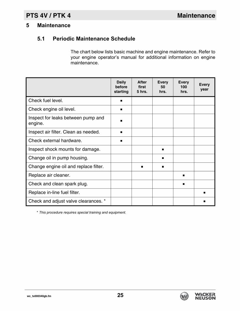
The chart below lists basic machine and engine maintenance. Refer toyour engine operator’s manual for additional information on enginemaintenance.
* This procedure requires special training and equipment.
Dailybefore
starting
Afterfirst
5 hrs.
Every50
hrs.
Every100 hrs.
Everyyear
Check fuel level.
Check engine oil level.
Inspect for leaks between pump and engine.
Inspect air filter. Clean as needed.
Check external hardware.
Inspect shock mounts for damage.
Change oil in pump housing.
Change engine oil and replace filter.
Replace air cleaner.
Check and clean spark plug.
Replace in-line fuel filter.
Check and adjust valve clearances. *
wc_tx000340gb.fm 25
Maintenance PTS 4V / PTK 4
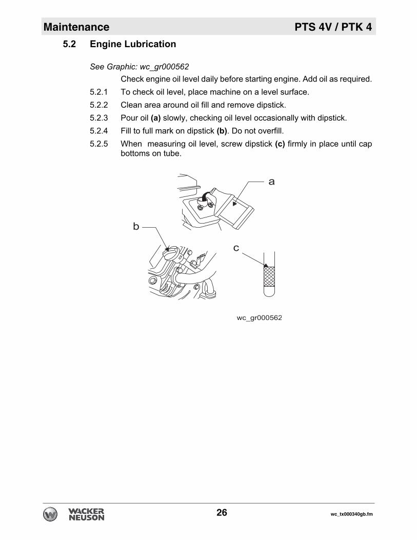
5.2 Engine LubricationSee Graphic: wc_gr000562Check engine oil level daily before starting engine. Add oil as required.
5.2.1 To check oil level, place machine on a level surface. 5.2.2 Clean area around oil fill and remove dipstick. 5.2.3 Pour oil (a) slowly, checking oil level occasionally with dipstick. 5.2.4 Fill to full mark on dipstick (b). Do not overfill.5.2.5 When measuring oil level, screw dipstick (c) firmly in place until cap
bottoms on tube.
26 wc_tx000340gb.fm

PTS 4V / PTK 4 Maintenance
5.3 Changing Oil FilterSee Graphic: wc_gr001482Replace the oil filter after every 100 hours of operation.
5.3.1 Drain the engine oil and replace it with fresh oil before removing theused oil filter. See Technical Data for oil quantity and type.Note: In the interests of environmental protection, place a plastic sheetand a container under the machine to collect any liquid which drainsoff. Dispose of this liquid in accordance with environmental protectionlegislation.
5.3.2 Remove the used filter before installing a new filter. Lightly oil the filtergasket with fresh, clean engine oil.
5.3.3 Screw the filter (a) on by hand until the gasket makes contact, thentighten an additional 1/2 to 3/4 turn.
5.3.4 Start and run the engine to check for leaks. Stop the engine. Recheckthe oil level and add oil if required. See Technical Data.
awc_gr001482
wc_tx000340gb.fm 27

Maintenance PTS 4V / PTK 4
5.4 Air CleanerSee Graphic: wc_gr000564Service air cleaner frequently to prevent carburetor malfunction. NOTICE: Do not run the engine without the air cleaner. Severe enginedamage will occur.Do not use gasoline or other types of low flash point solvents forcleaning the air cleaner. A fire or explosion could result.The engine is equipped with a dual element air cleaner. To service aircleaner:
5.4.1 Remove cover (a), knob (b), and retaining plate (c).5.4.2 Remove foam precleaner (d) from filter cartridge (e).5.4.3 Wash precleaner in liquid detergent and water. Squeeze dry in a clean
cloth. Saturate precleaner in engine oil, squeeze out excess oil.Replace precleaner if it is damaged or heavily soiled.
5.4.4 To clean cartridge, remove and tap lightly on a flat surface. Replacecartridge if it is damaged or heavily soiled.Note: To avoid damage to precleaner or cartridge when cleaningthem, do not use petroleum solvents or pressurized air.
28 wc_tx000340gb.fm

PTS 4V / PTK 4 Maintenance
5.5 Spark PlugSee Graphic: wc_gr000028Clean or replace the spark plug as needed to ensure proper operation.Refer to your engine operator’s manual. The muffler becomes very hot during operation and remains hot for awhile after stopping the engine. Do not touch the muffler while it is hot.
Note: Refer to section “Technical Data” for the recommended sparkplug type and the electrode gap setting.
5.5.1 Remove the spark plug and inspect it.5.5.2 Replace the spark plug if the insulator is cracked or chipped. 5.5.3 Clean the spark plug electrodes with a wire brush.5.5.4 Set the electrode gap (a).5.5.5 Tighten the spark plug securely.
NOTICE: A loose spark plug can become very hot and may causeengine damage.
WARNING
wc_tx000340gb.fm 29

Maintenance PTS 4V / PTK 4
5.6 Fuel FilterSee Graphic: wc_gr0014835.6.1 Change in-line fuel filter (a) once a year. 5.6.2 Check fuel lines and fittings frequently for cracks or leaks. Replace as
needed.Allow engine to cool and close fuel valve before replacing fuel filter.
5.7 Carburetor Adjustment
See Graphic: wc_gr000566Note: The air cleaner must be in place and the engine warm whenmaking adjustments to carburetor.
5.7.1 With engine running, place throttle in SLOW position and rotatecarburetor throttle lever against the idle speed screw (a) and hold itthere.
5.7.2 Turn the idle speed screw to obtain 1300 to 1500 rpm.5.7.3 While still holding the throttle lever against the idle speed screw, turn
the idle mixture valve (b) midway between the limits.5.7.4 Readjust the idle speed to 1200 rpm and release carburetor throttle
lever. Engine should accelerate smoothly when throttle is opened. If itdoes not, turn idle mixture valve slightly counterclockwise to readjust.
wc_gr001483
a
30 wc_tx000340gb.fm

PTS 4V / PTK 4 Maintenance
5.8 Changing Mechanical Seal CoolantSee Graphic: wc_gr001484Change mechanical seal coolant every 50 hours using SAE 30W oil.
5.8.1 Remove plugs (a) from both sides of pump housing for venting.5.8.2 Remove bottom plug (b) and allow oil to drain from oil cavity.5.8.3 Install bottom drain plug. 5.8.4 Fill oil cavity through one of the side plug (a) holes until oil is level with
top of hole or flows out hole on opposite side. Oil quantity - approximately 150 ml (5 ounces).
5.8.5 Install all plugs before operating pump.
a
b wc_gr001484
wc_tx000340gb.fm 31
Maintenance PTS 4V / PTK 4
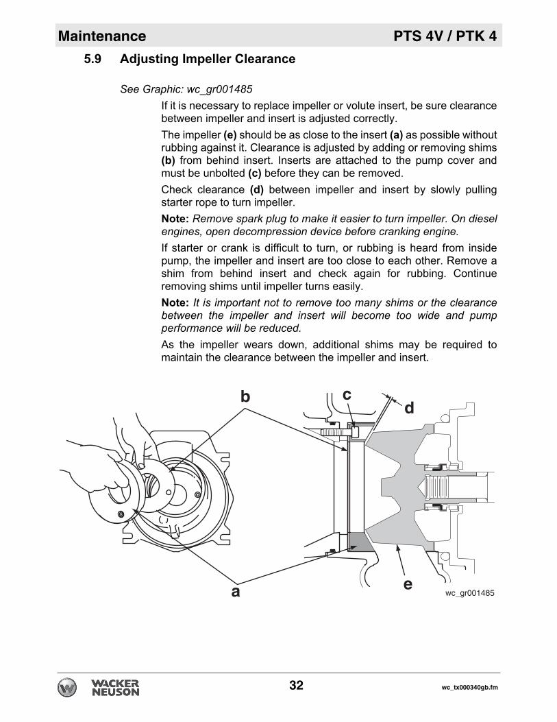
5.9 Adjusting Impeller ClearanceSee Graphic: wc_gr001485If it is necessary to replace impeller or volute insert, be sure clearancebetween impeller and insert is adjusted correctly. The impeller (e) should be as close to the insert (a) as possible withoutrubbing against it. Clearance is adjusted by adding or removing shims(b) from behind insert. Inserts are attached to the pump cover andmust be unbolted (c) before they can be removed. Check clearance (d) between impeller and insert by slowly pullingstarter rope to turn impeller. Note: Remove spark plug to make it easier to turn impeller. On dieselengines, open decompression device before cranking engine.If starter or crank is difficult to turn, or rubbing is heard from insidepump, the impeller and insert are too close to each other. Remove ashim from behind insert and check again for rubbing. Continueremoving shims until impeller turns easily.Note: It is important not to remove too many shims or the clearancebetween the impeller and insert will become too wide and pumpperformance will be reduced.As the impeller wears down, additional shims may be required tomaintain the clearance between the impeller and insert.
wc_gr001485ea
b cd
32 wc_tx000340gb.fm

PTS 4V / PTK 4 Maintenance
5.10 Cleaning PumpSee Graphic: wc_gr001486After pumping water containing a large amount of dirt or debris, cleanout inside of pump housing.
5.10.1 Remove drain plug (a) from pump housing and drain any water left inpump.
5.10.2 Loosen the four knobs (b) holding the pump cover and remove cover. 5.10.3 Clean out dirt and debris. Inspect impeller and volute insert for wear.
Note: Tighten cover evenly at all four corners using a wrench.The impeller may develop sharp edges. Use care when cleaningaround impeller to prevent getting cut.
CAUTION
a
b
wc_gr001486
wc_tx000340gb.fm 33
Maintenance PTS 4V / PTK 4
5.11 StorageIf pump is being stored for more than 30 days:
Do not open priming plug, discharge plug, or cover when pump is hot.
5.11.1 After pump has cooled, remove discharge plug from pump housingand drain out any water left in the housing.
5.11.2 Remove pump cover and clean inside of pump housing. Coat inside ofpump with a light film of oil to reduce corrosion. A spray can of oil workswell for this.
5.11.3 Tape up suction and discharge ports to prevent anything from fallinginto pump.
5.11.4 Change engine oil and follow procedures described in engine manualfor engine storage.
5.11.5 Cover pump and engine and store in a clean, dry area.
WARNING
34 wc_tx000340gb.fm
PTS 4V / PTK 4 Maintenance
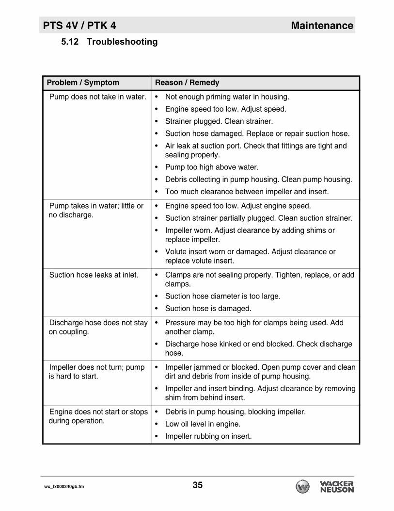
5.12 TroubleshootingProblem / Symptom Reason / Remedy
Pump does not take in water. • Not enough priming water in housing.
• Engine speed too low. Adjust speed.
• Strainer plugged. Clean strainer.
• Suction hose damaged. Replace or repair suction hose.
• Air leak at suction port. Check that fittings are tight and sealing properly.
• Pump too high above water.
• Debris collecting in pump housing. Clean pump housing.
• Too much clearance between impeller and insert.
Pump takes in water; little or no discharge.
• Engine speed too low. Adjust engine speed.
• Suction strainer partially plugged. Clean suction strainer.
• Impeller worn. Adjust clearance by adding shims or replace impeller.
• Volute insert worn or damaged. Adjust clearance or replace volute insert.
Suction hose leaks at inlet. • Clamps are not sealing properly. Tighten, replace, or add clamps.
• Suction hose diameter is too large.
• Suction hose is damaged.
Discharge hose does not stay on coupling.
• Pressure may be too high for clamps being used. Add another clamp.
• Discharge hose kinked or end blocked. Check discharge hose.
Impeller does not turn; pump is hard to start.
• Impeller jammed or blocked. Open pump cover and clean dirt and debris from inside of pump housing.
• Impeller and insert binding. Adjust clearance by removing shim from behind insert.
Engine does not start or stops during operation.
• Debris in pump housing, blocking impeller.
• Low oil level in engine.
• Impeller rubbing on insert.
wc_tx000340gb.fm 35
Technical Data PTS 4V / PTK 4
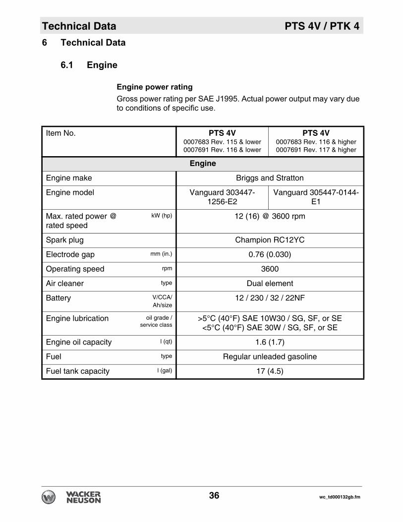
6 Technical Data6.1 Engine
Engine power ratingGross power rating per SAE J1995. Actual power output may vary dueto conditions of specific use.
Item No. PTS 4V0007683 Rev. 115 & lower0007691 Rev. 116 & lower
PTS 4V0007683 Rev. 116 & higher0007691 Rev. 117 & higher
Engine
Engine make Briggs and Stratton
Engine model Vanguard 303447-1256-E2
Vanguard 305447-0144-E1
Max. rated power @ rated speed
kW (hp) 12 (16) @ 3600 rpm
Spark plug Champion RC12YC
Electrode gap mm (in.) 0.76 (0.030)
Operating speed rpm 3600
Air cleaner type Dual element
Battery V/CCA/Ah/size
12 / 230 / 32 / 22NF
Engine lubrication oil grade /service class
>5°C (40°F) SAE 10W30 / SG, SF, or SE<5°C (40°F) SAE 30W / SG, SF, or SE
Engine oil capacity l (qt) 1.6 (1.7)
Fuel type Regular unleaded gasoline
Fuel tank capacity l (gal) 17 (4.5)
36 wc_td000132gb.fm

PTS 4V / PTK 4 Technical Data
6.2 Pump6.3 Sound Measurements
The required sound specifications per Appendix 1, Paragraph 1.7.4 ofthe EC-Machine Regulations, is:• the guaranteed sound power level (LWA) = 104 dB(A)
These sound values were determined according to ISO 3744 for thesound power (LWA).The sound measurements were obtained with the unit operating onpavement at nominal speed.
Item number: PTS 4V, PTK 4
Pump
Weight kg (lb) 163 (360)
*Max. suction lift m (ft) 7.5 (25)
Max. total head m (ft) 32 (106)
Mechanical seal lubrication oil grademl (oz.)
SAE 30150 (5)
Suction / discharge diameter mm (in.) 100 (4)
Max. solid size mm (in.) 50 (2)
*Based on pump operating at sea level. Maximum suction lift will be less at higher altitudes.
wc_td000132gb.fm 37

Technical Data PTS 4V / PTK 4
6.4 Dimensionsmm (in.)
890 (35) 915 (36)
890(35)
wc_gr001478
38 wc_td000132gb.fm

Emission Control Systems Information and Warranty
7 Emission Control Systems Information and WarrantyThe Emission Control Warranty and associated information is valid only for the U.S.A., its territories, and Canada.
7.1 Emission Control System Background InformationIntroductionWacker Neuson spark-ignited engines/equipment must conform with applicable Environmental Protection Agency (EPA) and the State of California emissions regulations. There are two types of emissions that fall under these regulations: 1) exhaust, and 2) evaporative. These regulations require that manufacturers warrant the emission control systems for defects in materials and workmanship.Furthermore, EPA and California regulations require all manufacturers to furnish written instructions describing how to operate and maintain the engines/equipment including the emission control systems. This information is provided with all Wacker Neuson engines/equipment at the time of purchase.
Exhaust EmissionsThe combustion process produces carbon monoxide, oxides of nitrogen, and hydrocarbons. Control of hydrocarbons and oxides of nitrogen is very important because, under certain conditions, they react to form photochemical smog when subjected to sunlight. Carbon monoxide does not react in the same way, but it is toxic.Wacker Neuson utilizes lean carburetor settings and other systems to reduce the emissions of carbon monoxide, oxides of nitrogen, and hydrocarbons.
Evaporative EmissionsEvaporative emissions are fuel emissions and generally include emissions that result from permeation of fuel through the fuel-system materials or from ventilation of the fuel system.Wacker Neuson utilizes low-permeation fuel lines and fuel tanks where applicable to reduce evaporative emissions.
Problems that may affect EmissionsIf any of the following symptoms arise, have the engine/equipment inspected and repaired by a Wacker Neuson dealer/service center.
Hard starting or stalling after startingRough idlingMisfiring or backfiring under loadAfterburning (backfiring)Presence of black exhaust smoke during operationHigh fuel consumption
wc_tx001754gb.fm 39

Emission Control Systems Information and Warranty
Tampering and AlteringTampering with or altering the emission control system may increase emissions beyond the legal limit. If evidence of tampering is found, Wacker Neuson may deny a warranty claim. Among those acts that constitute tampering are:Removing or altering of any part of the air intake, fuel, or exhaust systems.Altering or defeating the speed-adjusting mechanism causing the engine to operate outside its design parameters.
7.2 Limited Defect Warranty for Exhaust Emission Control System See the supplied engine owner’s manual for the applicable emission warranty statement.
40 wc_tx001754gb.fm

Emission Control Systems Information and Warranty
7.3 Limited Defect Warranty for Wacker Neuson EvaporativeEmission Control SystemsThe Emission Control Warranty is valid only for the U.S.A., its territories, and Canada. Wacker Neuson Sales Americas, LLC, N92 W15000 Anthony Avenue, Menomonee Falls, WI 53051, (hereinafter “Wacker Neuson”) warrants to the initial retail purchaser and each subsequent owner, that this engine/equipment, including all parts of its evaporative emission control system, have been designed, built, and equipped to conform at the time of initial sale to all applicable evaporative emission regulations of the U.S. Environmental Protection Agency (EPA), and that the engine/equipment is free of defects in materials and workmanship which would cause this engine/equipment to fail to conform to EPA regulations during its warranty period. Wacker Neuson is also liable for damages to other engine/equipment components caused by a failure of any warranted parts during the warranty period.
Limited Defect Warranty Period for Wacker Neuson Evaporative Emission Control SystemsThe warranty period for this engine/equipment begins on the date of sale to the initial purchaser and continues for a minimum of two (2) years. For the warranty terms for your specific engine/equipment, visit wackerneuson.com.Any implied warranties are limited to the duration of this written warranty.
What is covered Wacker Neuson recommends the use of genuine Wacker Neuson parts, or the equivalent, whenever maintenance is performed. The use of replacement parts not equivalent to the original parts may impair the effectiveness of the engine/equipment emission controls systems. If such a replacement part is used in the repair or maintenance of the engine/equipment, assure yourself that such part is warranted by its manufacturer to be equivalent to the parts offered by Wacker Neuson in performance and durability. Furthermore, if such a replacement part is used in the repair or maintenance of the engine/equipment, and an authorized Wacker Neuson dealer/service center determines it is defective or causes a failure of a warranted part, the claim for repair of the engine/equipment may be denied. If the part in question is not related to the reason the engine/equipment requires repair, the claim will not be denied.For the components listed in the following table, an authorized Wacker Neuson dealer/service center will, at no cost to you, make the necessary diagnosis, repair, or replacement necessary to ensure that the engine/equipment complies with the applicable EPA regulations. All defective parts replaced under this warranty become property of Wacker Neuson.
wc_tx001754gb.fm 41

Emission Control Systems Information and Warranty
What is not coveredFailures other than those resulting from defects in material or workmanship.Any systems or parts which are affected or damaged by owner abuse, tampering, neglect, improper maintenance, misuse, improper fueling, improper storage, accident and/or collision; the incorporation of, or any use of, add-on or modified parts, or unsuitable attachments, or the alteration of any part.Replacement of expendable maintenance items made in connection with required maintenance services after the item’s first scheduled replacement as listed in the maintenance section of the engine/equipment operator’s manual, such as spark plugs and filters.Incidental or consequential damages such as loss of time or the use of the engine/equipment, or any commercial loss due to the failure of the engine/equipment.Diagnosis and inspection charges that do not result in warranty-eligible service being performed.Any non-authorized replacement part, or malfunction of authorized parts due to use of-non authorized parts.
Owner’s Warranty ResponsibilityThe engine/equipment owner, is responsible for the performance of the required maintenance listed in the Wacker Neuson engine/equipment operator’s manual. Wacker Neuson recommends that all receipts covering maintenance on the engine/equipment be retained, but Wacker Neuson cannot deny warranty coverage solely for the lack of receipts or for the failure to ensure the performance of all scheduled maintenance.Normal maintenance, replacement, or repair of emission control devices and systems may be performed by any repair establishment or individual; however, warranty repairs must be performed by an authorized Wacker Neuson dealer/service center. The engine/equipment must be presented to an authorized Wacker Neuson dealer/service center as soon as a problem exists. Contact Wacker Neuson Product
System Covered ComponentsEvaporative emissions Fuel tank (if applicable)
Fuel tank cap (if applicable)Fuel line (if applicable)Fuel line fittings (if applicable)Clamps (if applicable)Carbon canister (if applicable)Purge port connector (if applicable)
Miscellaneous parts associated with the evaporative emission control system
ClampsGasketsMounting brackets
42 wc_tx001754gb.fm

Emission Control Systems Information and Warranty
Support Department (1-800-770-0957) or visit wackerneuson.com to find a dealer/service center in your area, or to answer questions regarding warranty rights and responsibilities.How to Make a ClaimIn the event that any emission-related part is found to be defective during the warranty period, you shall notify Wacker Neuson Product Support Department (1-800-770-0957), and you will be advised of the appropriate dealer/service center where warranty repair can be performed. All repairs qualifying under this limited warranty must be performed by an authorized Wacker Neuson dealer/service center.You must take your Wacker Neuson engine/equipment along with proof of original purchase date, at your expense, to the authorized Wacker Neuson dealer/service center during their normal business hours. For owners located more than 100 miles from an authorized dealer/service center (excluding the states with high-altitude areas as identified in 40 CFR Part 1068, Appendix III), Wacker Neuson will pay for pre-approved shipping costs to and from an authorized Wacker Neuson dealer/service center.Claims for repair or adjustment found to be caused solely by defects in material or workmanship will not be denied because the engine/equipment was not properly maintained and used.The warranty repairs should be completed in a reasonable amount of time, not to exceed 30 days.
wc_tx001754gb.fm 43

William Lahner Dan DomanskiVice President of Engineering Manager, Product Engineering
WACKER NEUSON CORPORATION
2010
-CE
-PT
S4V
-PT
K4_
en.fm
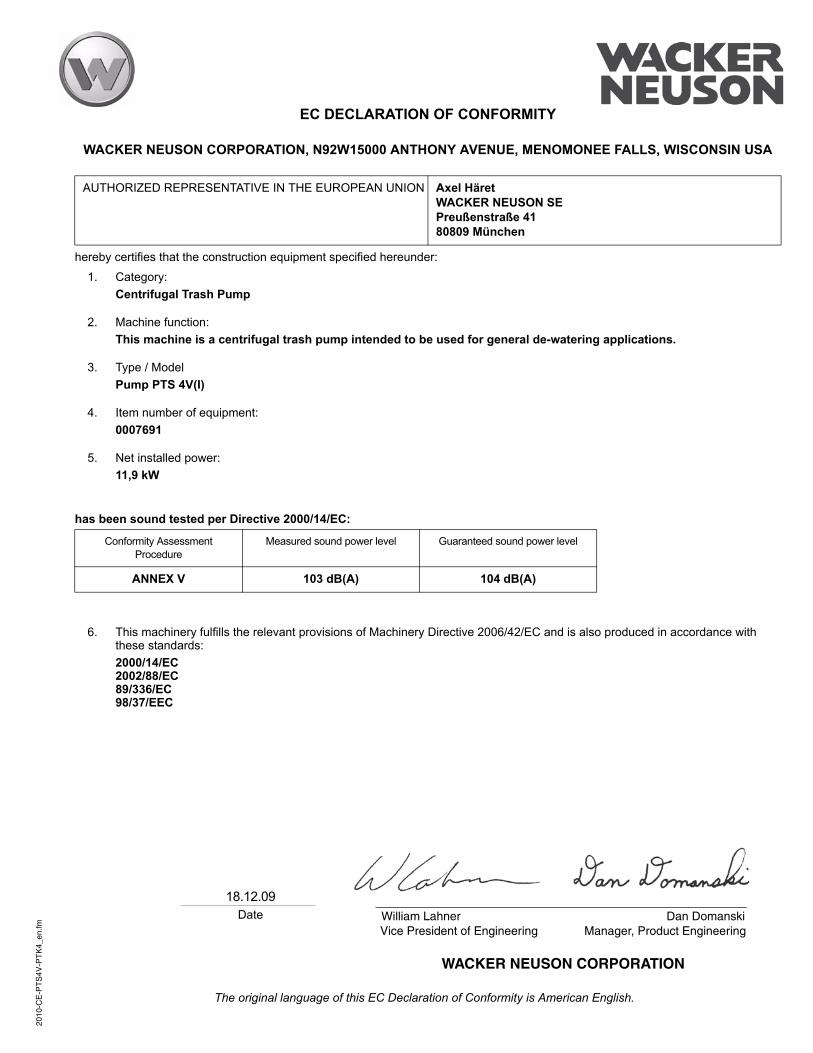
EC DECLARATION OF CONFORMITY
WACKER NEUSON CORPORATION, N92W15000 ANTHONY AVENUE, MENOMONEE FALLS, WISCONSIN USA
hereby certifies that the construction equipment specified hereunder:
has been sound tested per Directive 2000/14/EC:
AUTHORIZED REPRESENTATIVE IN THE EUROPEAN UNION Axel HäretWACKER NEUSON SEPreußenstraße 4180809 München
1. Category:Centrifugal Trash Pump
2. Machine function:This machine is a centrifugal trash pump intended to be used for general de-watering applications.
3. Type / ModelPump PTS 4V(I)
4. Item number of equipment:0007691
5. Net installed power:11,9 kW
Conformity Assessment Procedure
Measured sound power level Guaranteed sound power level
ANNEX V 103 dB(A) 104 dB(A)
6. This machinery fulfills the relevant provisions of Machinery Directive 2006/42/EC and is also produced in accordance with these standards:2000/14/EC2002/88/EC89/336/EC98/37/EEC
The original language of this EC Declaration of Conformity is American English.
18.12.09 Date


Wacker Neuson SE · Preußenstraße 41 · D-80809 München · Tel.: +49-(0)89-3 54 02-0 · Fax: +49 - (0)89-3 54 02-390Wacker Neuson Corporation · N92W15000 Anthony Ave. · Menomonee Falls, WI 53051 · Tel. : (262) 255-0500 · Fax: (262) 255-0550 ·Tel. : (800) 770-0957Wacker Neuson Limited - Room 1701–03 & 1717–20, 17/F. Tower 1, Grand Century Place, 193 Prince Edward Road West, Mongkok, Kowloon, Hongkong.Tel: (852) 3605 5360, Fax: (852) 2758 0032