operator’s manual - gardnerinc.com · operator’s manual manual del operador. electric...
TRANSCRIPT
OPERATOR’S MANUALManual del operador
ELECTRIC GENERATORGenerador electrico
HU40181 SeriesSerie HU40181
DANGER: You WILL be KILLED or SERIOUSLY HURT if you do not follow the instructions in this operator’s manual.
PELIGRO: El incumplimiento de las instrucciones en este manual del operador puede CAUSARLE LA MUERTE O LESIONARLE GRAVEMENTE.
To reduce the risk of injury, user must read and understand operator’s manual before using this generator.
Para reducir el riesgo de lesiones, el usuario debe leer y comprender el manual del operador antes de usar este generador.
SAVE THIS MANUAL FOR FUTURE REFERENCE
GUARDE ESTE MANUAL PARA FUTURAS CONSULTAS

�
TAbLE OF CONTENTS / TAbLE DES MATIERES / INDICE
ENGLISH
Safety and operation rules . . . . . . . . . . . . . . . . . . . . . . . . . . . . . . . 3
Spark arresting muffler . . . . . . . . . . . . . . . . . . . . . . . . . . . . . . . . . . 4
Operating voltage . . . . . . . . . . . . . . . . . . . . . . . . . . . . . . . . . . . . . . 4
Determining total wattage . . . . . . . . . . . . . . . . . . . . . . . . . . . . . . . . 4
Electrical . . . . . . . . . . . . . . . . . . . . . . . . . . . . . . . . . . . . . . . . . . . . . 5
Generator capacity . . . . . . . . . . . . . . . . . . . . . . . . . . . . . . . . . 5
Power management . . . . . . . . . . . . . . . . . . . . . . . . . . . . . . . . 5
Extension cord cable size . . . . . . . . . . . . . . . . . . . . . . . . . . . . 6
Electric motor loads . . . . . . . . . . . . . . . . . . . . . . . . . . . . . . . . 6
Major generator features . . . . . . . . . . . . . . . . . . . . . . . . . . . . . . . . . 7
Control panel . . . . . . . . . . . . . . . . . . . . . . . . . . . . . . . . . . . . . . . . . . 7
120 V, 15 ampere duplex receptacle . . . . . . . . . . . . . . . . . . . 7
Circuit breaker . . . . . . . . . . . . . . . . . . . . . . . . . . . . . . . . . . . . 7
Engine switch . . . . . . . . . . . . . . . . . . . . . . . . . . . . . . . . . . . . . 7
Battery charger . . . . . . . . . . . . . . . . . . . . . . . . . . . . . . . . . . . . 7
Installation . . . . . . . . . . . . . . . . . . . . . . . . . . . . . . . . . . . . . . . . . . . . 8
Before operation . . . . . . . . . . . . . . . . . . . . . . . . . . . . . . . . . . . . . . . 8
Grounding the generator . . . . . . . . . . . . . . . . . . . . . . . . . . . . 8
Lubrication . . . . . . . . . . . . . . . . . . . . . . . . . . . . . . . . . . . . . . . 9
Fuel . . . . . . . . . . . . . . . . . . . . . . . . . . . . . . . . . . . . . . . . . . . . . 9
Starting the unit . . . . . . . . . . . . . . . . . . . . . . . . . . . . . . . . . . . . . . . . 9
Pre-start preparation . . . . . . . . . . . . . . . . . . . . . . . . . . . . . . . 9
Starting the engine . . . . . . . . . . . . . . . . . . . . . . . . . . . . . . . . . 9
Applying load . . . . . . . . . . . . . . . . . . . . . . . . . . . . . . . . . . . . 10
Shutting the generator off. . . . . . . . . . . . . . . . . . . . . . . . . . . 10
Break-in procedure . . . . . . . . . . . . . . . . . . . . . . . . . . . . . . . . 10
Maintenance . . . . . . . . . . . . . . . . . . . . . . . . . . . . . . . . . . . . . . . . . 10
Generator: brushes . . . . . . . . . . . . . . . . . . . . . . . . . . . . . . . . 10
Inspecting the brushes . . . . . . . . . . . . . . . . . . . . . . . . . . . . . 10
Heat shield . . . . . . . . . . . . . . . . . . . . . . . . . . . . . . . . . . . . . . 10
Engine: carburetor icing . . . . . . . . . . . . . . . . . . . . . . . . . . . . 10
Quick starting tips for units that have been sitting a while . . . . . . . . . . . . . . . . . . . . . . 10
Fuel tank venting . . . . . . . . . . . . . . . . . . . . . . . . . . . . . . . . . . . . . . 11
Spark arrester muffler . . . . . . . . . . . . . . . . . . . . . . . . . . . . . . . . . . 11
Engine maintenance schedule . . . . . . . . . . . . . . . . . . . . . . . . . . . 11
Service and storage . . . . . . . . . . . . . . . . . . . . . . . . . . . . . . . . . . . 11
Infrequent service . . . . . . . . . . . . . . . . . . . . . . . . . . . . . . . . . 11
Long term storage . . . . . . . . . . . . . . . . . . . . . . . . . . . . . . . . 11
Limited warranty . . . . . . . . . . . . . . . . . . . . . . . . . . . . . . . . . . . . . . 12
Service information . . . . . . . . . . . . . . . . . . . . . . . . . . . . . . . . . . . . 12
Evaporative emission control warranty . . . . . . . . . . . . . . . . . . . . . 13
Limited 3-year engine warranty . . . . . . . . . . . . . . . . . . . . . . . . . . . 14
ESPAñOL
Reglas de seguridad y de funcionamiento . . . . . . . . . . . . . . . . . . 15
Apagachispas . . . . . . . . . . . . . . . . . . . . . . . . . . . . . . . . . . . . . . . . 16
Operating voltage . . . . . . . . . . . . . . . . . . . . . . . . . . . . . . . . . . . . . 16
Como determinar el vataje total . . . . . . . . . . . . . . . . . . . . . . . . . . 16
Aspectos eléctricos . . . . . . . . . . . . . . . . . . . . . . . . . . . . . . . . . . . . 17
Capacidad del generador . . . . . . . . . . . . . . . . . . . . . . . . . . . 17
Administración de la potencia . . . . . . . . . . . . . . . . . . . . . . . 17
Calibre del cordón de extensión. . . . . . . . . . . . . . . . . . . . . . 18
Cargas de motores eléctricos . . . . . . . . . . . . . . . . . . . . . . . 18
Caracteristicas principales del generador . . . . . . . . . . . . . . . . . . . 19
Panel de control . . . . . . . . . . . . . . . . . . . . . . . . . . . . . . . . . . . . . . 19
Receptáculo dúplex de 120 voltios, 15 amperes . . . . . . . . . 19
Interruptor . . . . . . . . . . . . . . . . . . . . . . . . . . . . . . . . . . . . . . . 19
Interruptor del motor . . . . . . . . . . . . . . . . . . . . . . . . . . . . . . 19
Cargador de batería . . . . . . . . . . . . . . . . . . . . . . . . . . . . . . . 19
Instalacion . . . . . . . . . . . . . . . . . . . . . . . . . . . . . . . . . . . . . . . . . . . 20
Antes de la operacion . . . . . . . . . . . . . . . . . . . . . . . . . . . . . . . . . . 20
Puesta a tierra del generador . . . . . . . . . . . . . . . . . . . . . . . . 20
Lubricacion . . . . . . . . . . . . . . . . . . . . . . . . . . . . . . . . . . . . . . 21
Combustible . . . . . . . . . . . . . . . . . . . . . . . . . . . . . . . . . . . . . 21
Arranque del unidad . . . . . . . . . . . . . . . . . . . . . . . . . . . . . . . . . . . 21
Preparacion antes de arrancar . . . . . . . . . . . . . . . . . . . . . . . 21
Arranque del motor. . . . . . . . . . . . . . . . . . . . . . . . . . . . . . . . 21
Como aplicar una carga . . . . . . . . . . . . . . . . . . . . . . . . . . . . 22
Apagado del generador . . . . . . . . . . . . . . . . . . . . . . . . . . . . 22
Procedimiento de arranque inicial . . . . . . . . . . . . . . . . . . . . 22
Mantenimiento . . . . . . . . . . . . . . . . . . . . . . . . . . . . . . . . . . . . . . . . 22
Generador: escobillas . . . . . . . . . . . . . . . . . . . . . . . . . . . . . 22
Para revisar las escobillas . . . . . . . . . . . . . . . . . . . . . . . . . . 22
Escudo de calor . . . . . . . . . . . . . . . . . . . . . . . . . . . . . . . . . . 22
Motor: congelamiento del carburador . . . . . . . . . . . . . . . . . 22
Consejos para un encendido rápido en unidades que han estado inhabilitadas durante un tiempo . . . . . . . . . . 22
Tanque del combustible descargar . . . . . . . . . . . . . . . . . . . . . . . . 23
Silenciador del arrestor de chispas . . . . . . . . . . . . . . . . . . . . . . . . 23
El horario de la mantenimientodel motor . . . . . . . . . . . . . . . . . . . 23
Servicio y almacenamiento . . . . . . . . . . . . . . . . . . . . . . . . . . . . . . 23
Servicio poco frecuente . . . . . . . . . . . . . . . . . . . . . . . . . . . . 23
Almacenamiento a largo plazo . . . . . . . . . . . . . . . . . . . . . . . 23
Garantia limitada . . . . . . . . . . . . . . . . . . . . . . . . . . . . . . . . . . . . . . 24
Servicio al cliente . . . . . . . . . . . . . . . . . . . . . . . . . . . . . . . . . . . . . 24
Garantía en relación con el control de emisiones evaporativas . . 25
Motor con garantía limitada de 3 años . . . . . . . . . . . . . . . . . . . . . 26
ENGLISH / ESPAñOL
Notes / notas . . . . . . . . . . . . . . . . . . . . . . . . . . . . . . . . . . . . . . . . . 27
Parts drawing / diagrama de piezas . . . . . . . . . . . . . . . . . . . . . . . 28
Parts list / lista de piezas . . . . . . . . . . . . . . . . . . . . . . . . . . . . . . . . 29
Notes / notas . . . . . . . . . . . . . . . . . . . . . . . . . . . . . . . . . . . . . . . . . 30
�
SAFETy INFORMATION
SAFETy AND OPERATION RULES
Read carefully and understand operator manual prior to operation of this product. Read and understand engine manual prior to operation. Follow all warnings and instructions.
Know your equipment. Consider the applications, limitations, and the potential hazards specific to your unit.
Equipment must be placed on a firm, supporting sur-face.
Load must be kept within rating stated on genera-tor nameplate. Overloading will damage the unit or shorten its life.
Engine must not be run at excessive speeds. Oper-ating an engine at excessive speeds increases the hazard of personal injury.
Do not tamper with parts which may increase or decrease the governed speed.
To prevent accidental starting, always remove the spark plug or cable from the spark plug before main-taining the generator or engine.
Units with broken or missing parts, or without pro-tective housing or covers, should never be operated. Contact your service center for replacement parts.
Units should not be operated or stored in wet or damp conditions or on highly conductive locations such as metal decking and steel work.
Keep the generator clean and free of oil, mud and other foreign matter.
Extension cords, power cords, and all electrical equipment must be in good condition. Never oper-ate electrical equipment with damaged or defective cords.
Store the generator in a well-ventilated area with the fuel tank empty. Fuel should not be stored near the generator.
Your generator should never be operated under these conditions:
a. Uncontrolled change in engine speed. (NOTE: The optional idle control feature will reduce the engine speed in a “No Load” condition.)
b. Electrical output loss.
c. Overheating in connected equipment.
d. Sparking.
e. Damaged receptacles.
f. Engine misfire.
g. Excessive vibration.
h. Flame or smoke.
i. Enclosed compartment.
j. Rain or inclement weather. Do not let the unit get wet when operating.
Check the fuel system periodically for leaks or signs of dete-rioration such as chafed or spongy hose, loose or missing clamps, or damaged tank or cap. All defects should be cor-rected before operation.
The generator should be operated, serviced, and refueled only under the following conditions:
a. Start and run the generator outdoors. Do not run the gen-erator in an enclosed area, even if doors or windows are open; avoid areas where vapors may be trapped, such as pits, garages, cellars, excavations and boat bilges.
b. Good ventilation for cooling. Air flow and temperatures are important for air cooled units. Temperatures should not exceed 104°F ambient (40°C).
c. Refuel the generator in a well lighted area. Avoid fuel spills and never refuel while the generator is running. Allow engine to cool for two minutes prior to refueling.
d. Do not refuel near open flames, pilot lights, or sparking electrical equipment such as power tools, welders, and grinders.
e. The muffler and air cleaner must be installed and in good condition at all times as they function as flame arresters if backfiring occurs.
f. Do not smoke near the generator.
DANGER:DANGER indicates a potentially hazardous situation which, if not avoided, WILL result in death or serious injury.
wARNING:WARNING indicates a potentially hazardous situation which, if not avoided, could result in death or serious injury.
CAUTION:CAUTION indicates a potentially hazardous situation which, if not avoided, may result in minor or moderate personal injury, or property damage.
wARNING:Failure to follow these instructions and warnings can result in death, personal injury, or property damage.
DANGER:CARbON MONOXIDE HAZARD: The engine exhaust contains carbon monoxide, a poisonous, odorless, invisible gas which, if breathed, can cause death or serious personal injury. If you start to feel sick, dizzy
or weak while using the generator, shut it off and get to fresh air right away; you may have carbon monoxide poisoning.

�
OPERATING VOLTAGE Ensure that generator is properly grounded. (See
“Grounding the generator” section in this manual.)
Do not wear loose clothing, jewelry, or anything that may be caught in the starter or other rotating parts.
Unit must reach operating speed before electrical loads are connected. Disconnect loads before turn-ing off engine.
To prevent surging that may possibly damage equip-ment, do not allow engine to run out of fuel when electrical loads are applied.
When powering solid state equipment, a Power Line Conditioner should be used to avoid possible dam-age to equipment.
Do not stick anything through ventilating slots, even when the generator is not operating. This can dam-age the generator or cause personal injury.
Before transporting the generator in a vehicle, drain all fuel to prevent leakage that may occur.
Use proper lifting techniques when transporting the generator from site to site. Improper lifting tech-niques may result in personal injury.
To avoid burns, do not touch engine muffler or other engine or generator surfaces which became hot dur-ing operation.
Do not alter or modify the heat shield.
yOUR PRODUCT MAy NOT bE EQUIPPED wITH A SPARK ARRESTING MUFFLER. If the product will be used around flammable materials, such as agricultural crops, for-ests, brush, grass, or other similar items, then an approved spark arrester should be installed and is legally required in the State of California. The California statutes requiring a spark arrester are Sections 13005(b), 4442 and 4443. Spark Arresters are also required on some U.S. Forest Service land and may also be legally required under other statutes and ordinances. An approved spark arrester is available from our product dealers, or may be ordered from Techtronic Industries North America, Inc., P.O. Box 35, Highway 8, Pickens, SC 29671, 1-866-340-3912.
SPARK ARRESTING MUFFLER
A power line conditioner should be used when any of the following solid state items:
Garage door openers
Kitchen appliances with digital displays
Televisions
Stereos
Personal computers
Quartz clocks
Copy machines
Telephone equipment
DETERMINING TOTAL wATTAGE
In order to prevent overloading and possible damage to your generator it is necessary to know the total wattage of the connected load. To determine which tools and/or appliances your generator will run follow these steps:
Determine if you want to run one item or multiple items simul-taneously.
Check wattage requirements for the items you will be running by referring to the load’s nameplate or by calculating it (mul-tiply amps x volts = watts).
Total the watts for each item. If the nameplate only gives volts and amps, multiply volts x amps = watts.
1 Kw = 1,000 watts
Motorized appliances or tools require more than their rated wattage for start up.
NOTE: Allow 2-1/2 to 4 times the listed wattage for start-ing equipment powered by electric motors.
The generator’s rated watts should match or exceed the total number of watts required for the equipment you want to run.
Always connect the heaviest load to the generator first, then add other items one at a time.
CAUTION:Operating voltage and frequency requirement of all electronic equipment should be checked prior to plugging them into this generator. Damage may result if the equipment is not designed to operate within a +/- 10% voltage variation, and +/- 3 hz frequency variation from the generator name plate ratings. To avoid damage, always have an additional load plugged into the generator if solid state equipment (such as a television set) is used. A power line conditioner is recommended for some solid state applications.
�
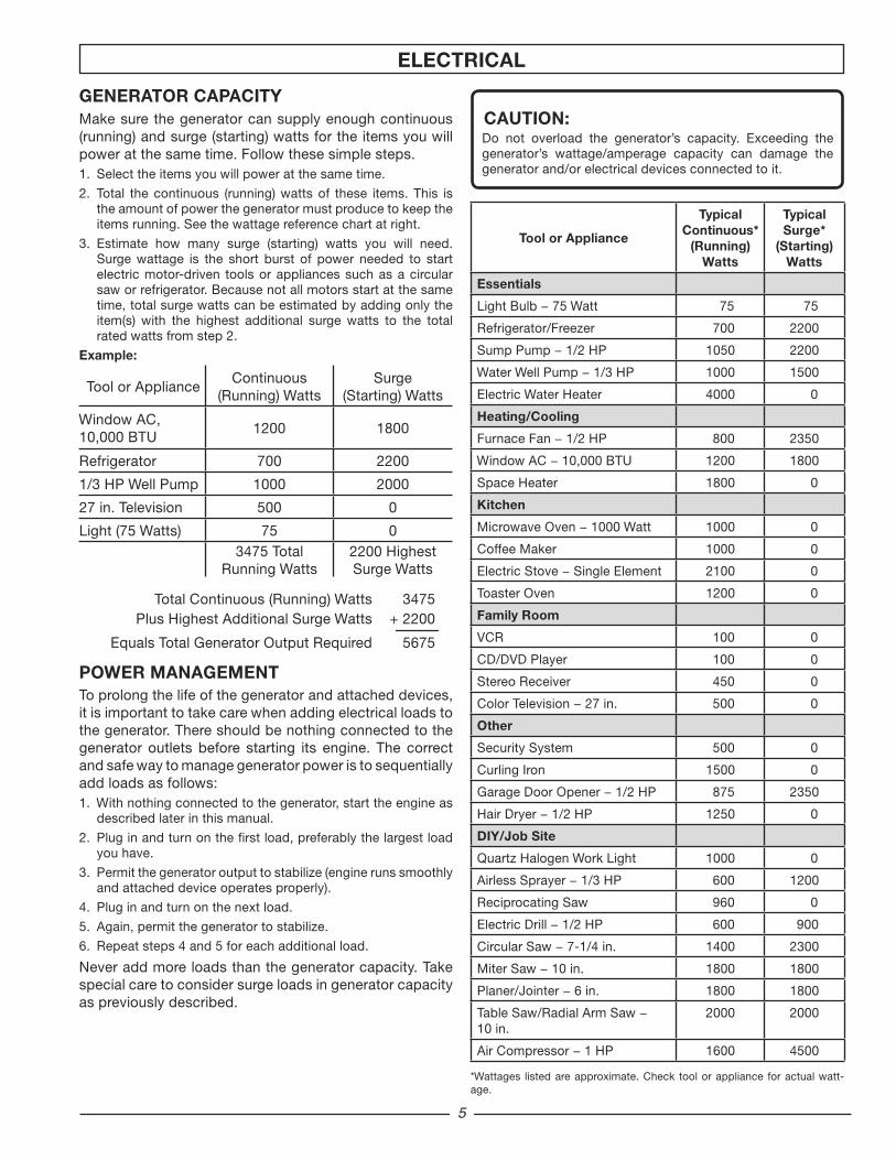
GENERATOR CAPACITyMake sure the generator can supply enough continuous (running) and surge (starting) watts for the items you will power at the same time. Follow these simple steps.1. Selecttheitemsyouwillpoweratthesametime.
2. Total thecontinuous (running)wattsof these items.This isthe amount of power the generator must produce to keep the items running. See the wattage reference chart at right.
3. Estimate how many surge (starting) watts you will need.Surge wattage is the short burst of power needed to start electric motor-driven tools or appliances such as a circular saw or refrigerator. Because not all motors start at the same time, total surge watts can be estimated by adding only the item(s) with the highest additional surge watts to the total rated watts from step 2.
Example:
Tool or ApplianceContinuous
(Running) WattsSurge
(Starting) Watts
Window AC, 10,000 BTU
1200 1800
Refrigerator 700 2200
1/3 HP Well Pump 1000 2000
27 in. Television 500 0
Light (75 Watts) 75 03475 Total
Running Watts2200 Highest Surge Watts
Total Continuous (Running) Watts 3475 Plus Highest Additional Surge Watts + 2200
Equals Total Generator Output Required 5675
POwER MANAGEMENTTo prolong the life of the generator and attached devices, it is important to take care when adding electrical loads to the generator. There should be nothing connected to the generator outlets before starting its engine. The correct and safe way to manage generator power is to sequentially add loads as follows:1. With nothing connected to the generator, start the engine as
described later in this manual.
2. Plug in and turn on the first load, preferably the largest load you have.
3. Permit the generator output to stabilize (engine runs smoothly and attached device operates properly).
4. Plug in and turn on the next load.
5. Again, permit the generator to stabilize.
6. Repeat steps 4 and 5 for each additional load.
Never add more loads than the generator capacity. Take special care to consider surge loads in generator capacity as previously described.
Tool or Appliance
TypicalContinuous*
(Running) watts
Typical Surge*
(Starting) watts
Essentials
LightBulb−75Watt 75 75
Refrigerator/Freezer 700 2200
SumpPump−1/2HP 1050 2200
WaterWellPump−1/3HP 1000 1500
Electric Water Heater 4000 0
Heating/Cooling
FurnaceFan−1/2HP 800 2350
WindowAC−10,000BTU 1200 1800
Space Heater 1800 0
Kitchen
MicrowaveOven−1000Watt 1000 0
Coffee Maker 1000 0
ElectricStove−SingleElement 2100 0
Toaster Oven 1200 0
Family Room
VCR 100 0
CD/DVD Player 100 0
Stereo Receiver 450 0
ColorTelevision−27in. 500 0
Other
Security System 500 0
Curling Iron 1500 0
GarageDoorOpener−1/2HP 875 2350
HairDryer−1/2HP 1250 0
DIy/Job Site
Quartz Halogen Work Light 1000 0
AirlessSprayer−1/3HP 600 1200
Reciprocating Saw 960 0
ElectricDrill−1/2HP 600 900
CircularSaw−7-1/4in. 1400 2300
MiterSaw−10in. 1800 1800
Planer/Jointer−6in. 1800 1800
TableSaw/RadialArmSaw−10 in.
2000 2000
AirCompressor−1HP 1600 4500
*Wattages listed are approximate. Check tool or appliance for actual watt-age.
ELECTRICAL
CAUTION:Do not overload the generator’s capacity. Exceeding the generator’s wattage/amperage capacity can damage the generator and/or electrical devices connected to it.
�
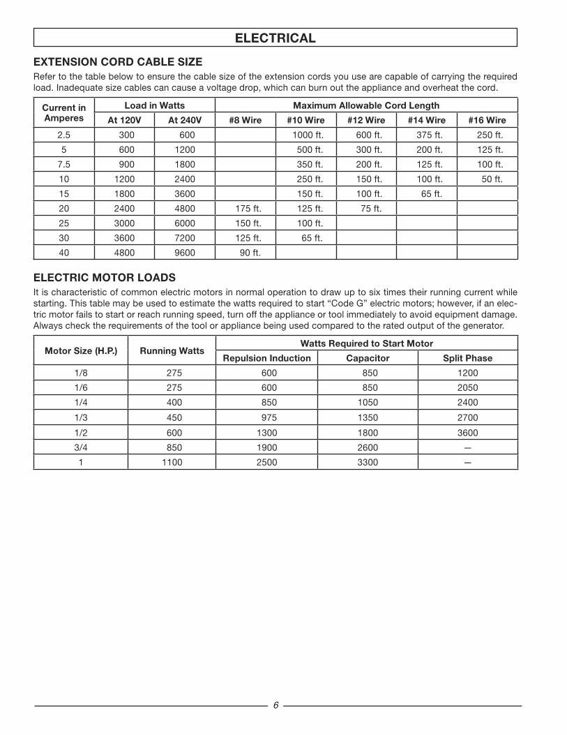
EXTENSION CORD CAbLE SIZERefer to the table below to ensure the cable size of the extension cords you use are capable of carrying the required load. Inadequate size cables can cause a voltage drop, which can burn out the appliance and overheat the cord.
Current inAmperes
Load in watts Maximum Allowable Cord Length
At 120V At 240V #8 wire #10 wire #12 wire #14 wire #16 wire
2.5 300 600 1000 ft. 600 ft. 375 ft. 250 ft.
5 600 1200 500 ft. 300 ft. 200 ft. 125 ft.
7.5 900 1800 350 ft. 200 ft. 125 ft. 100 ft.
10 1200 2400 250 ft. 150 ft. 100 ft. 50 ft.
15 1800 3600 150 ft. 100 ft. 65 ft.
20 2400 4800 175 ft. 125 ft. 75 ft.
25 3000 6000 150 ft. 100 ft.
30 3600 7200 125 ft. 65 ft.
40 4800 9600 90 ft.
ELECTRIC MOTOR LOADSIt is characteristic of common electric motors in normal operation to draw up to six times their running current while starting. This table may be used to estimate the watts required to start “Code G” electric motors; however, if an elec-tric motor fails to start or reach running speed, turn off the appliance or tool immediately to avoid equipment damage. Always check the requirements of the tool or appliance being used compared to the rated output of the generator.
Motor Size (H.P.) Running wattswatts Required to Start Motor
Repulsion Induction Capacitor Split Phase
1/8 275 600 850 1200
1/6 275 600 850 2050
1/4 400 850 1050 2400
1/3 450 975 1350 2700
1/2 600 1300 1800 3600
3/4 850 1900 2600 —
1 1100 2500 3300 —
ELECTRICAL

�
MAJOR GENERATOR FEATURESSubaru OHC engine
Receptacles on endbell
Battery charger
1.5 gallon fuel tank
Spark arrester
Brushless generator
CONTROL PANEL
A . 120 V, 15 Ampere Duplex Receptacle
15 amps of current may be drawn from each half of the receptacle. However, total power drawn must be kept within nameplate ratings.
b. Circuit breaker
The receptacles are protected by an AC circuit breaker. If the generator is overloaded or an external short circuit occurs, the circuit breaker will trip. If this occurs, disconnect all electri-cal loads and try to determine the cause of the problem before attempting to use the generator again. If overloading causes the circuit breaker to trip, reduce the load. NOTE: Continuous trip-ping of the circuit breaker may cause damage to generator or equipment. The circuit breaker may be reset by pushing the button of the breaker.
C. Engine Switch
The battery charger on this generator is referred to as an unregulated taper charger - the most widely used in the market today. The amount of current flowing will depend on the charging voltage and battery’s state of charge. As the battery becomes more fully charged, the output current to the battery decreases and nearly becomes constant. Taper chargers are intended to be used with the provision that they will be disconnected from the battery after a maximum time on charge. Normally a period of 30 to 120 minutes is sufficient to recharge a weak battery. The charge level of the battery should be checked periodically.
RECEPTACLE PANEL RECOIL PANEL
D. battery Charger
NOT RECOMMENDED FOR USE wITH GEL PACK, SEALED OR SMALL (MOTORCyCLE) bATTERIES.
This generator contains an additional circuit used for bat-tery charging purposes. A DC accessory receptacle is provided on the control panel. A battery charging cable equipped with a matching plug for this receptacle has been supplied with the unit. Line up metal prongs on plug with arrows on receptacle to secure.
NOTE: When the battery charger circuit is in use, the AC capacity is reduced by 180 watts. Make sure the combined load is within the rated limits.
Before charging a storage battery, check the electrolyte fluid level in all the cells. Add distilled water to each cell, if necessary, to bring the level back up to the manufacturer’s required level.
CAUTION:This battery charging system is intended to recharge weak batteries, not to “boost start” vehicles. Do not overcharge battery or leave battery unattended.
Use cables approved for battery charging. Connect a red clip to the positive terminal of the battery. Connect a black clip to the negative terminal of the battery. Connect the other end of the cable to the DC accessory receptacle on the genera-tor panel. After the battery is fully charged, remove the battery charging cable from the generator and then disconnect from the battery posts.
wARNING:Storage batteries give off EXPLOSIVE hydrogen gas while charging. Do not allow smoking, open flames,sparks, or spark producing equipment in the area while charging.
DC CIRCUIT bREAKER: The maximum current available from the battery charger circuit is 15 amps. An automatic DC circuit breaker has been provided to protect the circuit from over-loads and assure that the battery gets recharged. If an overload occurs, the circuit breaker will trip. After it cools, it will auto-matically reset itself. The battery’s maximum rate of charge will eventually reduce to less than 15 amps and then to zero as the battery approaches a 100 percent state of charge.
wARNING:Battery electrolyte fluid is comprised of sulfuric acid that can be very dangerous and cause severe burns. Do not allow this fluid to contact eyes, skin, clothing, etc. If contact or spillage does occur, flush the area with water immediately.
wARNING:Do not continue to charge a battery that becomes hot or is fully charged.

�
wARNING:Do not use a pipe as the ground source.
INSTALLATION bEFORE OPERATION
wARNING:To avoid possible personal injury or equipment damage, registered electrician or an authorized service representative should perform installation and all service. Under no circumstances should an unqualified person attempt to wire into a utility circuit.
wARNING:To avoid backfeeding into utility systems, isolation of the residence electrical system is required. Before temporary connection of a generator to the residence electrical system turn off the main switch. Before making permanent connections a double throw transfer switch To avoid electrocution or property damage, only a trained electrician should connect generator to residence electrical system. California law requires isolation of the residence electrical system before connecting a generator to residence electrical systems. Temporary connection not recommended due to backfeeding.
To avoid backfeeding into utility systems, isolation of the residence electrical system is required.
Before temporary connection of the generator to the resi-dence electrical system, turn off the main service/disconnect.
If your generator is to be used as a stand-by power source in case of utility power failure, it should be installed by a reg-istered electrician and in compliance with all applicable local electrical codes.
Proper use requires that a double throw transfer switch be installed by a licensed qualified electrician so that the building’s electrical circuits may be safely switched between utility power and the generator’s output, thereby preventing backfeed into the power utility’s electrical system.
Always follow local codes and regulations that apply to the installation of any item that concerns this product.
GROUNDING THE GENERATOR
The National Electric Code requires that this product be properly connected to an appropriate earth ground to help pre-vent electric shock. A ground terminal connected to the frame of the generator has been provided for this purpose. Connecting a length of heavy gauge (12 AWG min.) copper wire between the generator Ground Terminal and a copper rod driven into the ground should provide a suitable ground connection. However, consult with a local electrician to insure that local codes are being adhered to.
GROUND TERMINAL LOCATION:
ground lug
�
LUbRICATION
Operating the unit without lubricant can damage the engine.
Fill the engine with lubricant according to the engine man-ual. For units with a dipstick, fill lubricant to the proper level. Units without a dipstick should be filled to the top of the opening of the lubricant fill.
FUEL
Fill the tank with clean, fresh unleaded automotive gasoline. Regular grade gasoline may be used provided a high octane rating is obtained (at least 85 pump octane). We recommend always using a fuel stabilizer. A fuel stabilizer will minimize the formulation of fuel gum deposits during storage. The fuel sta-bilizer can be added to the gasoline in the fuel tank, or into the gasoline in a storage container. Do not use E85 fuel.
CAUTION:Do not overfill the tank. Keep maximum fuel level 1/4 inch below the top of the fuel tank. This will allow expansion in hot weather and prevent overflow.
STARTING THE UNIT
wARNING:Gasoline is very dangerous. Serious injury or death can result from fire caused by gasoline contacting hot surfaces.
Do not fill fuel tank with engine running.
Do not spill fuel while refilling tank.
Do not mix oil with gasoline.
Follow all instructions and warnings in the engine manual.
PRE-START PREPARATION
Before starting the generator, check for loose or missing parts and for any damage which may have occurred during shipment.
wARNING:This generator must not be operated without all factory installed heat shields in place. Failure to comply may cause the fuel tank to overheat and result in personal injury from fire.
STARTING THE ENGINE
Check lubricant level and fuel.
Disconnect all electrical loads from the unit.
Open fuel shut off valve.
Adjust choke as necessary.
Set the engine switch to the “ON” position.
Pull on the starter rope with fast steady pull. As the engine warms up, readjust the choke.
DANGER: Provide adequate ventilation for toxic exhaust gases and
cooling air flow.
Do not start or run the generator in an enclosed area, even if door or windows are open.
Engines give off carbon monoxide, an odorless, colorless, poison gas.
Breathing carbon monoxide can cause nausea, fainting or death.
CAUTION:Allow generator to run at no load for five minutes upon each initial start-up to permit engine and generator to stabilize.
10
APPLyING LOAD
This unit has been pretested and adjusted to handle its full capacity. When starting the generator, disconnect all load. Apply load only after generator is running. Voltage is regulated via the engine speed adjusted at the factory for correct output. Read-justing will void warranty.
CAUTION:When applying a load, do not exceed the maximum wattage rating of the generator when using one or more receptacles. Also, do not exceed the amperage rating of any one receptacle.
SHUTTING THE GENERATOR OFF
Remove entire electrical load.
Let the engine run for a few minutes without load.
Move the engine switch to the “OFF” position.
Do not leave the generator until it has completely stopped.
Close the fuel shut off valve if the engine is to be put in stor-age or transported.
If cover is used, do not install until unit has cooled.
bREAK-IN PROCEDURE
Controlled break-in helps insure proper engine and gen-erator operation. Follow engine procedure outlined in engine manual.
CAUTION:Do not apply heavy electrical load during break-in period (the first two to three hours of operations).
MAINTENANCE
GENERATOR: bRUSHES (bRUSH TyPE UNITS ONLy)
The brushes in the generator should be inspected once every year for chips and cracks. Brushes should be replaced when they are worn to 1/4 inch (7 mm).
NOTE: Replace brushes in sets only, never separately.
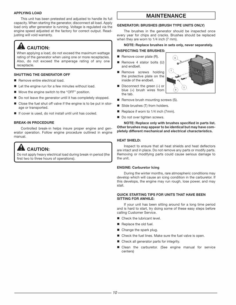
INSPECTING THE bRUSHES:
Remove cover plate (R).
Remove 4 stator bolts (U) and endbell.
Remove screws holding the protective plate on the inside of the endbell.
Disconnect the green (–) or blue (+) brush wires from the tab.
Remove brush mounting screws (S).
Slide brushes (T) from holders.
Replace if worn to 1/4 inch (7mm).
Do not over tighten screws.
NOTE: Replace only with brushes specified in parts list. Other brushes may appear to be identical but may have com-pletely different mechanical and electrical characteristics.
HEAT SHIELD:
Inspect to ensure that all heat shields and heat deflectors are intact and in place. Do not remove any parts or modify parts. Removing or modifying parts could cause serious damage to the unit.
ENGINE: Carburetor Icing
During the winter months, rare atmospheric conditions may develop which will cause an icing condition in the carburetor. If this develops, the engine may run rough, lose power, and may stall.
QUICK STARTING TIPS FOR UNITS THAT HAVE bEEN SITTING FOR AwHILE:
If your unit has been sitting around for a long time period and is hard to start, try doing some of these easy steps before calling Customer Service.
Check the lubricant level.
Replace the old fuel.
Change the spark plug.
Check the fuel lines. Make sure the fuel valve is open.
Check all generator parts for integrity.
Clean the carburetor. (See engine manual for service centers)

11
FUEL TANK VENTING
CAUTION:Keep fuel tank area free of all debris, water, and ice. Do not block vent. “Tank must breathe.”
SPARK ARRESTER MUFFLERThis engine is equipped with a spark arrest muffler. It should
periodically be cleaned to prevent the screen from becoming clogged, which could hamper engine performance.
To clean, remove the muffler shield. Remove the four screws and pull the plate with the screen attached. Clean off any par-ticles with a brush and reinstall. Be sure gasket is in place.
ENGINE MAINTENANCE SCHEDULE
Check engine lubricant . . . . . . . . . . . . . . . . . Before each useChange engine lubricant . . . . . . . After first 20 hours and then every 50 hours of operation
Clean air filter . . . . . . . . . . . . . . . . Every 50 hours of operationClean spark plug. . . . . . . . . . . . . Every 100 hours of operationClean spark arrestor . . . . . . . . . . Every 50 hours of operation
Lubricant Type. Use new good quality lubricant such as SC, SD, and SE grades. The lubricant to be used depends upon the temperature at which the engine is operated:
Summer: (temperatures of over 40°F/10°C) SAE 30 or SAE 10W-30, SAE 10W-40
winter: (temperatures of below 40°F/10°C) SAE 20 or SAE 10W-30
SERVICE AND STORAGE
INFREQUENT SERVICE
If the unit is used infrequently, difficult starting may result. to eliminate hard starting, run the generator at least 30 minutes every month. Also, if the unit will not be used for some time, it is a good idea to drain the fuel from the carburetor and gas tank.
LONG TERM STORAGE
When the generator set is not being operated or is being stored more than one month, follow these instructions:
Replenish engine lubricant to upper level.
Drain gasoline from fuel tank, fuel line and carburetor.
a) Turn the engine switch off ( O ).
b) Closefuelvalve.
c) Removethefuel linefromthepetcockbysqueezingtheends of the retaining clip and sliding the fuel line off.
d) Installoneendofadrainlineoverthepetcock,andplacethe other end in a fuel container large enough to catch the fuel being drained from the tank.
e) Openfuelvalve.
f) When the fuelhasdrained from the tank,close the fuelvalve and reinstall fuel line on petcock.
Pour about one teaspoon of engine lubricant through the spark plug hole, pull the recoil starter several times and replace the plug. Then pull the starter until you feel the pis-ton is on its compression stroke and leave it in that position. This closes both the intake and exhaust valves to prevent the inside of the cylinder from rusting.
Cover the unit and store in a clean, dry place that is well ven-tilated away from open flame or sparks.
NOTE: we recommend always using a fuel stabilizer. A fuel stabilizer will minimize the formulation of fuel gum deposits during storage. The fuel stabilizer can be added to the gasoline in the fuel tank, or into the gasoline in a storage container.
1�
SERVICE INFORMATION
CONTACT HUSKy CUSTOMER SERVICE AT
1-866-340-3912
to obtain warranty service information or to order replacement parts or
accessories. HOw TO ORDER REPLACEMENT PARTS
Even quality built equipment such as the electric generator you have purchased, might need occasional replacement parts to maintain it in good condition over the years. To order replace-ment parts, please give the following information:
Model No. and Serial No. and all specifications shown on the Model No./Serial No. plate.
Part number or numbers as shown in the Parts List section of the Insert for your generator model.
A brief description of the trouble with the generator.
NOTE: If replacement parts are required for the engine, contact one of the engine manufacturer’s service centers.
Techtronic Industries North America, Inc.P.O. box 35, Highway 8
Pickens, SC 296711-866-340-3912
LIMITED wARRANTy
wARRANTy COVERAGE
Techtronic Industries North America, Inc., (the Company) warrants to the original retail purchaser that this Husky Product is free from defects in material and workmanship and agrees to repair or replace, at the Company’s sole discretion, any defective Product free of charge within these time periods from the date of purchase:
Two years, if the Product is used solely for personal, family, or household use;
One year, if the Product is used for business or commercial use.
This warranty applies only to Products sold within the United States of America, the District of Columbia, Canada, Mexico, the Commonwealth of Puerto Rico, the Virgin Islands, Guam, the Canal Zone, or American Samoa.
This warranty is not transferable and does not cover damage resulting from defects other than in material or workmanship, or damage caused by unreasonable use, including the failure to provide reasonable and necessary maintenance. Other items not covered under this warranty include:
Transportation charges for sending the product to the Company or its authorized service representative for warranty service, or for shipping repaired or replacement products back to the customer; these charges must be borne by the original retail purchaser.
Engine. Your Product is equipped with an engine that is covered exclusively by a separate warranty from the engine manufacturer. Please refer to the engine manual included with the Product for warranty information related to the engine.
Damages caused by abuse, accident, misuse, neglect, alteration, modification, the effects of corrosion, erosion, normal wear and tear or repairs by other than the Company or its authorized service representative.
Warranty is voided if the customer fails to install, maintain and operate the product in accordance with the instructions and recommendations of the Company as set forth in the Product’s operator’s manual or if the Product is used as rental equipment.
The Company will not pay for repairs or adjustments to the Product, or for any costs or labor, performed without the Company’s prior authorization.
SAVE yOUR SALES SLIP
Proof of purchase in the form of your dated sales receipt, cash register slip, etc. showing the serial number and the model of your Product will be required before the Company and/or its authorized service representatives can perform warranty service on the Product.
EXCLUSIONS AND LIMITATIONS
THIS LIMITED wARRANTy IS IN LIEU OF ALL OTHER EXPRESS wARRANTIES. ANY IMPLIED WARRANTY OF MERCHANTABILITY, FITNESS FOR A PARTICULAR PURPOSE, OR OTHERWISE, APPLICABLE TO THIS PRODUCT, SHALL BE LIMITED IN DURATION TO THE DURATION OF THIS LIMITED WARRANTY. THE WARRANTY SERVICE DESCRIBED ABOVE IS THE EXCLUSIVE REMEDY UNDER THIS WARRANTY. THE COMPANY SHALL NOT BE LIABILE FOR ANY SPECIAL, INCIDENTAL OR CONSEQUENTIAL DAMAGES.
SOME STATES DO NOT ALLOW A LIMITATION ON THE DURATION OF IMPLIED WARRANTIES, OR THE EXCLUSION OR LIMITATION OF INCIDENTAL, OR CONSEQUENTIAL DAMAGES, SO THE ABOVE LIMITATION OR EXCLUSION MAY NOT APPLY TO YOU.
HOw TO ObTAIN wARRANTy SERVICE
For warranty service: Call toll free 1-866-340-3912, or write to Techtronic Industries North America, Inc., P.O. box 35, High-way 8, Pickens, SC 29671.
For warranty service outside the USA, please contact your local Husky dealer.

1�
EVAPORATIVE EMISSION CONTROL wARRANTy
Your new HUSKY brand gasoline-powered product complies with all applicable U.S. EPA, Environment Canada, and State of California emissions regulations.
The evaporative emissions portion of this coverage, as described be-low, is provided by Techtronic Industries North America, Inc. Separate emissions warranty coverage for other emissions-related components is provided by the engine manufacturer, as stated in a separate “Emission Control System Warranty” included with this product. Of course, this product also includes a warranty that is not limited to emissions-related components, as described elsewhere in this operator’s manual.
EVAPORATIVE EMISSION CONTROL WARRANTY STATEMENT
CALIFORNIA EVAPORATIVE EMISSION CONTROL wARRANTy STATEMENT
yOUR wARRANTy RIGHTS AND ObLIGATIONS
The California Air Resources Board and Techtronic Industries North America, Inc., are pleased to explain the evaporative emission control system’s warranty on your 2008 model year generator. In California, new equipment that uses small off-engines must be designed, built, and equipped to meet the State’s stringent anti-smog standards. Techtronic Industries North America, Inc., must warrant the evaporative emission control system on your generator for the period listed below, provided there has been no abuse, neglect or improper maintenance of your equipment.
Your evaporative emission control system may include parts such as: carburetors, fuel tanks, fuel lines, fuel caps, valves, canisters, filters, vapor hoses, clamps, connectors, and other associated components. For engines less than or equal to 80 cc, only the fuel tank is subject to the evaporative emission control warranty requirements of this section.
MANUFACTURER’S wARRANTy COVERAGE:
This evaporative emission control system is warranted for two years. If any evaporative emission-related part on your equipment is defective, the part will be repaired or replaced by Techtronic Industries North America, Inc.
OwNER’S wARRANTy RESPONSIbILITIES:
As the generator owner, you are responsible for performance of the required maintenance listed in your operator’s manual. Techtronic Industries North America, Inc., recommends that you retain all receipts covering maintenance on your generator, but Techtronic Industries North America, Inc., cannot deny warranty solely for the lack of receipts.
As the generator owner, you should, however, be aware that Tech-tronic Industries North America, Inc., may deny you warranty cover-age if your generator or a part has failed due to abuse, neglect, or improper maintenance or unapproved modifications.
You are responsible for presenting your generator to a Techtronic Industries North America, Inc., distribution center or service center as soon as the problem exists. The warranty repairs should be com-pleted in a reasonable amount of time, not to exceed 30 days.
If you have a question regarding your warranty coverage, you should con-tact Techtronic Industries North America, Inc., at 1-866-340-3912.
DEFECTS wARRANTy REQUIREMENTS:
(a) The warranty period begins on the date the equipment is delivered to an ultimate purchaser.
(b) General Evaporative Emissions Warranty Coverage. The equipment must be warranted to the ultimate purchaser and any subsequent owner that the evaporative emission control system when installed was:
(1) Designed, built, and equipped so as to conform with all appli-cable regulations; and
(2) Free from defects in materials and workmanship that cause the failure of a warranted part for a period of two years.
(c) The warranty on evaporative emissions-related parts will be inter-preted as follows:
(1) Any warranted part that is not scheduled for replacement as required maintenance in the written instructions must be war-ranted for the warranty period defined in subsection (b)(2). If any such part fails during the period of warranty coverage, it must be repaired or replaced by the manufacturer issuing the warranty. Any such part repaired or replaced under the warranty must be warranted for a time not less than the remaining warranty period.
(2) Any warranted part that is scheduled only for regular inspection in the written instructions must be warranted for the warranty period defined in subsection (b)(2). A statement in such written instructions to the effect of “repair or replace as necessary” will not reduce the period of warranty coverage. Any such part repaired or replaced under warranty must be warranted for a time not less than the remaining warranty period.
(3) Any warranted part that is scheduled for replacement as required maintenance in the written instructions must be warranted for the period of time prior to the first scheduled replacement point for that part. If the part fails prior to the first scheduled replace-ment, the part must be repaired or replaced by the manufacturer issuing the warranty. Any such part repaired or replaced under warranty must be warranted for a time not less than the remain-der of the period prior to the first scheduled replacement point for the part.
(4) Repair or replacement of any warranted part under the warranty provisions of this article must be performed at no charge to the owner at a warranty station.
(5) Notwithstanding the provisions of subsection (4) above, warranty services or repairs must be provided at distribution centers that are franchised to service the subject equipment.
(6) The owner must not be charged for diagnostic labor that leads to the determination that a warranted part is in fact defective, provided that such diagnostic work is performed at a warranty station.
(7) Throughout the evaporative emission control system’s warranty period set out in subsection (b)(2), the manufacturer issuing the warranty must maintain a supply of warranted parts sufficient to meet the expected demand for such parts.
(8) Manufacturer approved replacement parts must be used in the performance of any warranty maintenance or repairs and must be provided without charge to the owner. Such use will not reduce the warranty obligations of the manufacturer issuing the warranty.
(9) The use of any add-on or modified parts will be grounds for disallowing a warranty claim made in accordance with this article. The manufacturer issuing the warranty will not be liable under this Article to warrant failures of warranted parts caused by the use of an add-on or modified part.
(10) The manufacturer issuing the warranty shall provide any docu-ments that describe the warranty procedures or policies within five working days of request by the Air Resources Board.
EMISSION wARRANTy PARTS LIST:
1) Fuel Tank
2) Fuel Cap
3) Fuel Hoses
4) Carbon Canister
5) Vapor Hoses
6) Hose Clamps
7) Hose Connectors
8) Vapor/Fuel Check Valve
Written instructions for the maintenance and use of the evaporative emissions control system by the owner shall be furnished with each new generator.
wARRANTy

1�
LIMITED 3-yEAR ENGINE wARRANTy
Limited Manufacturer’s warranty from Subaru Robin
(Effective with engines purchased from Robin America, Wood Dale, IL, after April 1, 2008)
Robin America, Inc., a division of Fuji Heavy Industries, Ltd. (herein “Subaru Robin”), warrants that each new engine sold by it will be free, under normal use and service, from defects in material and workmanship for a period listed below from the date of sale to the original retail purchaser. Subaru Robin’s obligation under this Limited Warranty shall be lim-ited to the repair and replacement, at Subaru Robin’s option, of any part or parts which upon examination is/are found, in Subaru Robin’s judgment, to have been defective in material or workmanship. It shall be a condition of Subaru Robin’s obligation under this Limited Warranty that Subaru Robin, directly or through one of its Distributors or Service Centers authorized to service the particular engine involved, receive prompt notice of any warranty claim and that the engine or the part or parts claimed to be defective be promptly delivered, transportation prepaid, to such Distributor or Service Center for inspection and repair. All repairs qualifying under this Limited Warranty must be performed by Subaru Robin or one of its authorized Distributors or Service Centers.
wARRANTy PERIODS:
Subaru Robin Four-Cycle, Air-cooled, Gasoline Engines - Limited 3 yEAR warranty (EX / EH Series 4.3hp or greater)
The repair or replacement of any part or parts under this Limited Warranty shall not extend the term of the engine war-ranty beyond the original term as set forth above.
LIMITATIONS AND EXCLUSIONS: This Limited Warranty shall not apply to:
Bent or broken crankshaft or resultant damage caused by vibration related to a bent or broken crankshaft. Also, damage caused by loose engine mounting bolts or improper or imbalanced accessories or blades mounted to the crankshaft.
Repairs required because of prolonged storage including damage caused by old or contaminated fuel in the fuel tank, fuel lines or carburetor, sticky valves or corrosion and rust of engine parts.
Repair required due to overheating. (Most often caused by overloaded or clogged or damaged or missing flywheel, fan, inlet air passages, cooling fins or air shrouds).
Dirt or grit related wear caused by improper air cleaner maintenance (most often resulting in worn piston, piston rings, cylinders, valves, valve guides, carburetor or other internal components).
Broken or scored parts caused by low lubricant level, dirty or improper grade of lubricant.
Engine tune-ups and normal maintenance service including, but not limited to, valve adjustment, normal replace-ment of service items, fuel and lubricant, etc.
Any engine which has been subject to negligence, misuse, accident, mis-application or over-speeding.
Any engine that has been installed, repaired, or altered by anyone in a manner which in Subaru Robin’s sole judg-ment adversely affects its performance or reliability.
Any engine which has been fitted with or repaired with parts or components not manufactured or approved by Subaru Robin which in Subaru Robin’s sole judgment adversely affects its performance or reliability.
Instances when normal use has exhausted the life of a component or an engine.
The customer is responsible for all transportation charges in connection with any warranty work.
Subaru Robin reserves the right to modify, alter or improve any engines or parts without incurring any obligation to modify or replace, any engine or parts previously sold without such modification, alternation or improvement.
No person is authorized to give any other warranty or to assume any additional obligation on Subaru Robin’s behalf unless made in writing and signed by an officer of Subaru Robin.
Some states do not allow limitations on how long an implied warranty lasts or the exclusion or limitation of incidental or consequential damages, so the above limitation(s) or exclusion(s) may not apply to you. This warranty gives you specific legal rights and you may also have other legal rights which vary from state to state.
THIS WARRANTY, AND SUBARU ROBIN’S OBLIGATION HERE UNDER, ARE IN LIEU OF ANY OTHER WARRANTIES OR OBLIGATIONS OF ANY KIND, EXPRESSED OR IMPLIED, INCLUDING ANY WARRANTIES OF MERCHANTABIL-ITY OR FITNESS FOR A PARTICULAR PURPOSE. THERE ARE NO WARRANTIES WHICH EXTEND BEYOND THE DESCRIPTION ON THE FACE HERE-OF. SUBARU ROBIN SHALL IN NO EVENT BE LIABLE FOR ANY CONSEQUEN-TIAL OR INCIDENTAL DAMAGES.
1�
SEGURIDAD
Lea cuidadosamente y entienda el manual del operador antes de utilizar este producto. Lea y entienda el manual del motor antes de su funcionamiento. Siga todas las advertencias e instrucciones.
Conozca su equipo. Considere las aplicaciones, limitaciones y los riesgos potenciales específicos de su unidad.
El equipo deberá colocarse sobre una base de sustentación firme.
La carga debe mantenerse dentro de los valores nominales que aparecen en la placa de identificación del generador. Una sobrecarga dañará la unidad o acortará su vida útil.
No se debe hacer funcionar el motor a velocidades demasiado altas. Si se opera el motor a excesiva velocidad aumenta el riesgo de lesiones físicas. No toque o cambie piezas que puedan aumentar o disminuirla velocidad regulada.
Para evitar un arranque inesperado, siempre retire la bujía o el cable de la bujía antes de dar mantenimiento al generador o al motor.
Nunca debe operarse una unidad con piezas quebradas o faltantes, o sin el revestimiento o cubiertas protectoras. Comuniquese con su centro de servicio para solicitar los repuestos.
Las unidades no deben operarse ni almacenarse en lugares húmedos o mojados ni altamente conductores tales como plataformas metálicas o estructuras de acero.
Mantenga el generador limpio y libre de aceite, barro y cualquier otro material extraño.
Los cordones de extensión, los cordones eléctricos y todos los equipos eléctricos deben estar en buenas condiciones. Nunca opere un equipo eléctrico con cordones dañados o defectuosos.
Guarde el generador en un lugar con buena ventilación, con el tanque de combustible vacío. No se debe almacenar combustible cerca del generador.
Su generador no deberá operarse jamás si ocurre do lo siguiente:
a. Cambio fuera de control en la velocidad del motor. (NOTA: la característica opcional control en descanso reducirá la velocidad del motor a una condición “Sin carga”).
b. Pérdida de carga eléctrica. c. Sobrecalentamiento del equipo conectado. d. Formación de chispas. e. Receptáculos dañados. f. Fallo de encendido. g. Vibración excesiva. h. Llamas o humo. i. Compartimiento cerrado. j. Lluvia o inclemencia del tiempo. No permita que la unidad
se moje cuando está funcionando. Verifique periódicamente que no haya salideros o señales
de deterioro en el sistema de combustible, como manguera demasiado gastada o blanda, abrazaderas flojas o faltantes, o tanque o tapón dañados. Todos estos defectos deberán corregirse antes de la operación.
El generador debe operarse, recibir servicio y rellenarse de combustible solamente en las siguientes condiciones:
a. Encienda y ponga a funcionar el generador al aire libre. No ponga a funcionar el generador en un área cerrada, aun cuando las puertas o ventanas se encuentren abiertas; evite áreas en donde los vapores puedan encerrarse, tales como pozos, garajes, sótanos, excavaciones y pantoques.
b. Buena ventilación para el enfriamiento. La circulación de aire y las temperaturas son importantes para las unidades enfriadas por aire. Las temperaturas no deberían exceder 104°F (40°C) a temperatura ambiente.
c. Eche combustible al generador en un área bien iluminada. Evite derramamiento de combustible y nunca rellene con combustible mientras el generador está funcionando. Antes de echar combustible, espere que el motor se enfríe durante dos minutos.
d. No eche combustible cerca de llamas, luces piloto o equipos eléctricos con chispas como herramientas mecánicas, soldadores y rectificadoras.
PELIGRO:PELIGRO indica una situación potencialmente peligrosa que, si no se evita, PROVOCARÁ muerte o una lesión seria.
ADVERTENCIA:ADVERTENCIA indica una situación de peligro potencial, la cual, si no se evita, podría ocasionar lesiones severas e incluso la muerte.
PRECAUCIÓN:PRECAUCIÓN indica una situación potencialmente de riesgo, la cual, si no se evita, puede ocasionar heridas personales menores o moderadas o daños materiales.
ADVERTENCIA:El no seguir estas instrucciones y advertencias puede ocasionar la muerte, heridas personales o daños materiales.
PELIGRO:RIESGO DE MONÓXIDO DE CARbONO: El escape del motor contiene monóxido de carbono, un gas venenoso, inodoro, invisible que, si se inhala puede provocar la muerte o una lesión personal seria. Si
comienza a sentirse indispuesto, mareado o débil mientras uti liza el generador, apáguelo e inmediatamente vaya a un lugar fresco; podría padecer de envenenamiento por monóxido de carbono.
REGLAS DE SEGURIDAD y DE FUNCIONAMIENTO

1�
EL REQUERIMIENTO DE VOLTAJE e. Deberá instalar el silenciador y filtro de aire, los
cuales deberán estar buenas condiciones en todo momento ya que detienen el fuego en caso de una explosión incompleta en el motor.
f. No fume cerca del generador.
Cerciórese de el generador esté conectado a tierra correctamente (Consulte la sección Conexión a tierra del generador).
No use ropa demasiado holgada, alhajas o cualquier otra cosa que pueda quedar atrapada en el arrancador u otras partes movibles.
La unidad debe alcanzar la velocidad de operación antes de conectarse las cargas eléctricas. Desconecte las cargas antes de apagar el motor.
Para evitar sobrecargas que podrían dañar al equipo, no permita que el motor se quede sin combustible al aplicarse las cargas eléctricas.
Al dar carga a un equipo de estado sólido, debe utilizarse un protector de sobrecarga para evitar posibles daños al equipo.
No coloque nada a través de las ranuras de ventilación, aun cuando el generador no esté en operación. Esto puede dañar al generador o causar lesiones personales.
Antes de transportar el generador en un vehículo, extraiga todo el combustible para evitar la posibilidad de salideros o derrames.
Use técnicas correctas de alzaje al mover el generador de un lugar a otro. De lo contrario, podrían producirse lesiones personales.
Para evitar quemaduras, no toque el silenciador del motor u otras superficies del generador que se hayan calentado durante la operación.
No modifique el escudo contra el calor.
PUEDE SER QUE SU PRODUCTO NO ESTE EQUIPADO CON UN SILENCIADOR APAGACHISPAS. Si el producto se va a utilizar cerca de materiales inflamables como son cosechas agrícolas, bosques, arbustos, pastos, etc., debe entonces instalarse un apagachispas adecuado. Esto es obligatorio en el estado de California, de acuerdo con las secciones de estatutos 13005(b), 4442 y 4443. Los apagachispas son también obligatorios en algunas tierras del Servicio Forestal de los EE.UU. y quizá también según otros estatutos u ordenanzas legales. Existen apagachispas de uso aprobado en nuestro distribuidors. También puede encargarse a Techtronic Industries North America, Inc., P.O. Box 35, Highway 8, Pickens, SC 29671, 1-866-340-3912.
Se deberá utilizar un acondicinador de línea de conducción cuando se operen uno o más de los siguientes equipos de estado sólido:
Control para abrir la cochera o garajeEquipos de cocina con visualización digitalTelevisoresEstéreosComputadoras personalesRelojes de cuarzoMáquinas fotocopiadorasEquipo telefónico
A fin de evitar la sobrecarga y los posibles daños a su generador, resulta necesario conocer el vataje total de la carga conectada. Para determinar qué herramientas y/o equipos electrodomésticos su generador hará funcionar, siga los pasos a continuación:
Determine sí desea hacer funcionar un aparato o varios aparatos simultáneamente.
Verifque los requerimientos de potencia de arranque y de funcionamiento de los aparatos fijándose en las carga especificada en la etiqueta, o calculándola (multiplique amperios x voltios = watts o potencia).
Sume la potencia necesaria de arranque y de funcionamiento de cada aparato. Sí la etiqueta sólo le da el voltaje y el amperaje, entonces multiplique Voltios x Amperios = Watts. 1Kw = 1,000 watts.
Los electrodomésticos o herramientas impulsadas por motores requieren más potencia que lo especificado para arrancar.
NOTA: Permita 2 1/2 - 4 veces el vataje mencionado para arrancar al equipo.
Los vatios unitarios del generador deberían coincidir o superar el número total de vatios que requiere el equipo que usted desea arrancar.
Siempre conecte la carga más grande primero, y luego agregue los demás equipos uno por uno.
PRECAUCIÓN:El requerimiento de voltaje y frecuencia operativa de todos los equipos electrónicos debe comprobarse antes de enchufarlos a este generador. Pueden ocurrir daños si el equipo no está diseñado para operar dentro de una variación de voltaje de +/-10% y una variación de frecuencia de +/-3 hz de los valores nominales que aparecen en la placa de identificación del generador. A fin de evitar daños, siempre tenga una carga adicional enchufada al generador en caso de usarse equipos de estado sólido (tales como un aparato de televisión). También podría resultar necesario un condicionador de la línea eléctrica para algunas aplicaciones; por ejemplo, con una computadora. También podria resultar necesario un condicionador de la línea eléctrica para algunas aplicaciones de equipo de estado sólido.
APAGACHISPAS
COMO DETERMINAR EL VATAJE TOTAL
1�
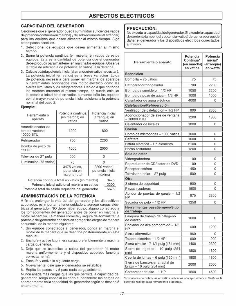
CAPACIDAD DEL GENERADORCerciórese que el generador pueda suministrar suficientes vatios de potencia continua (en marcha) y de sobrecorriente (al arrancar) para los equipos que desee alimentar al mismo tiempo. Siga estos pasos sencillos.1. Seleccione los equipos que desea alimentar al mismo
tiempo.2. Sume lapotenciacontinua (enmarcha)envatiosdeestos
equipos. Esta es la cantidad de potencia que el generador debe producir para mantener en marcha los equipos. Observe la tabla de referencia de potencia en vatios, a la derecha.
3. Calculecuántapotenciainicial(alarranque)envatiosnecesitará.La potencia inicial (en vatios) es la breve variación rápida de potencia necesaria para poner en marcha los aparatos o herramientas accionados con motor eléctrico como las sierras circulares o los refrigeradores. Debido a que no todos los motores arrancan al mismo tiempo, se puede calcular la potencia inicial total en vatios sumando sólo los equipos con el mayor valor de potencia inicial adicional a la potencia nominal del paso 2.
Ejemplo:
Herramienta o aparato
Potencia continua (en marcha) en
vatios
Potencia inicial(arranque) en
vatios
Acondicionador de aire de ventana, 10000 BTU
1200 1800
Refrigerador 700 2200
Bomba de pozo de 1/3 HP 1000 2000
Televisor de 27 pulg 500 0
Iluminación (75 vatios) 75 03475 vatios,potencia en marcha total
2200 vatios, potencia inicial
máxima
Potencia continua total en vatios (en marcha) 3475 Potencia inicial adicional máxima en vatios + 2200 Potencia total de salida requerida del generador 5675
ADMINISTRACIÓN DE LA POTENCIAA fin de prolongar la vida útil del generador y los dispositivos acoplados, es importante tener cuidado al agregar cargas eléc-tricas al generador. NO debe haber equipo alguno conectado a los tomacorrientes del generador antes de poner en marcha el motor respectivo. La manera correcta y segura de administrar la potencia del generador consiste en agregar las cargas de manera secuencial de la manera siguiente:1. Sin equipos conectados al generador, ponga en marcha el
motor de la manera que se describe posteriormente en este manual.
2. Enchufe y active la primera carga, preferiblemente la máxima carga que tenga.
3. Deje que se estabilice la salida del generador (el motor marcha uniformemente y el dispositivo acoplado funciona correctamente).
4. Enchufe y active la siguiente carga.5. Nuevamente, deje que el generador se estabilice.6. Repita los pasos 4 y 5 para cada carga adicional.Nunca añada más cargas que las que permita la capacidad del generador. Tenga especial cuidado al considerar las cargas de sobrecorriente en la capacidad del generador según se describió anteriormente.
Herramienta o aparato
PotenciaContinua*
(en marcha) en vatios
Potencia inicial*
(arranque) en watts
Esenciales
Bombilla−75vatios 75 75
Refrigerador/congelador 700 2200
Bombadesumidero−1/2HP 1050 2200Bombadepozodeagua−1/3HP 1000 1500Calentador de agua eléctrico 4000 0Calefacción/RefrigeraciónVentiladordecalefacción−1/2HP 800 2350Acondicionador de aire de ventana −10000BTU 1200 1800
Calentador de locales 1800 0CocinaHornodemicroondas−1000vatios 1000 0Cafetera 1000 0Estufaeléctrica−Unelemento 2100 0Horno-tostadora 1200 0Sala de estarVideograbadora 100 0Reproductor de CD/lector de DVD 100 0Receptor estéreo 450 0Televisoracolor−27pulg 500 0OtraSistema de seguridad 500 0Pinzas rizadoras 1500 0Abridordepuertasdegaraje−1/2HP 875 2350
Secadordepelo−1/2HP 1250 0Herramientas pasatiempos/Sitio de trabajoLámpara de trabajo de halógeno de cuarzo 1000 0
Rociadordeairecomprimido−1/3HP 600 1200
Sierra alternativa 960 0Taladroeléctrico−1/2HP 600 900Sierra circular - 7-1/4 pulg (184 mm) 1400 2300Sierra de ingletes − 10 pulg (254mm) 1800 1800
Cepillodejuntas−6pulg(150mm) 1800 1800Sierra de banco/sierra radial de brazo−10pulg(254mm) 2000 2000
Compresordeaire−1HP 1600 4500
*Los valores de potencias en vatios indicados son aproximados. Verifique la potencia real de cada herramienta o aparato.
PRECAUCIÓN: No exceda la capacidad del generador. Si excede la capacidad de corriente (amperios) y potencia (vatios) del generador puede dañar el generador y los dispositivos eléctricos conectados al mismo.
ASPECTOS ELéCTRICOS
1�
ASPECTOS ELéCTRICOS
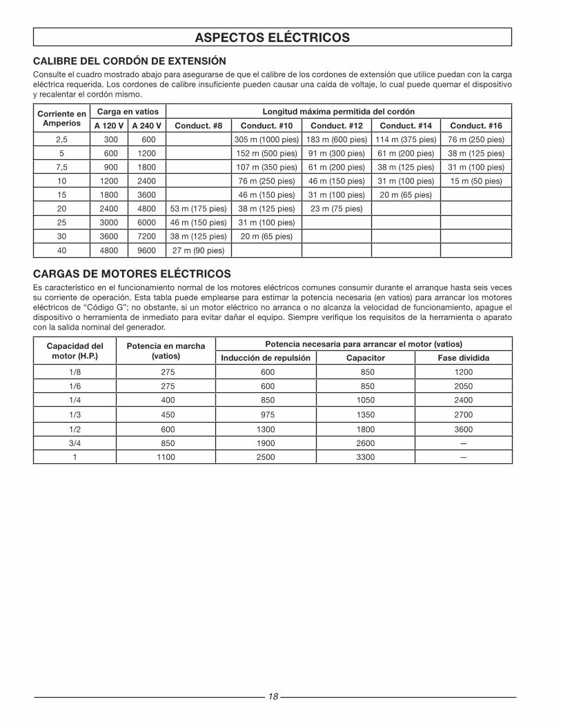
CALIbRE DEL CORDÓN DE EXTENSIÓNConsulte el cuadro mostrado abajo para asegurarse de que el calibre de los cordones de extensión que utilice puedan con la carga eléctrica requerida. Los cordones de calibre insuficiente pueden causar una caída de voltaje, lo cual puede quemar el dispositivo y recalentar el cordón mismo.
Corriente en Amperios
Carga en vatios Longitud máxima permitida del cordón
A 120 V A 240 V Conduct. #8 Conduct. #10 Conduct. #12 Conduct. #14 Conduct. #16
2,5 300 600 305 m (1000 pies) 183 m (600 pies) 114 m (375 pies) 76 m (250 pies)
5 600 1200 152 m (500 pies) 91 m (300 pies) 61 m (200 pies) 38 m (125 pies)
7,5 900 1800 107 m (350 pies) 61 m (200 pies) 38 m (125 pies) 31 m (100 pies)
10 1200 2400 76 m (250 pies) 46 m (150 pies) 31 m (100 pies) 15 m (50 pies)
15 1800 3600 46 m (150 pies) 31 m (100 pies) 20 m (65 pies)
20 2400 4800 53 m (175 pies) 38 m (125 pies) 23 m (75 pies)
25 3000 6000 46 m (150 pies) 31 m (100 pies)
30 3600 7200 38 m (125 pies) 20 m (65 pies)
40 4800 9600 27 m (90 pies)
CARGAS DE MOTORES ELéCTRICOSEs característico en el funcionamiento normal de los motores eléctricos comunes consumir durante el arranque hasta seis veces su corriente de operación. Esta tabla puede emplearse para estimar la potencia necesaria (en vatios) para arrancar los motores eléctricos de “Código G”; no obstante, si un motor eléctrico no arranca o no alcanza la velocidad de funcionamiento, apague el dispositivo o herramienta de inmediato para evitar dañar el equipo. Siempre verifique los requisitos de la herramienta o aparato con la salida nominal del generador.
Capacidad del motor (H.P.)
Potencia en marcha (vatios)
Potencia necesaria para arrancar el motor (vatios)
Inducción de repulsión Capacitor Fase dividida
1/8 275 600 850 1200
1/6 275 600 850 2050
1/4 400 850 1050 2400
1/3 450 975 1350 2700
1/2 600 1300 1800 3600
3/4 850 1900 2600 —
1 1100 2500 3300 —

1�
Motor Subaru OHC
Receptáculos sobre el placa lateral
Cargador de batería
Tanque de combustible con capacidad de 5.7 litros (1.5 galone)
Apagachispas
El generador sin escobillas
A. Receptáculo dúplex de 120 voltios, 15 amperes
15 amperes de la corriente se pueden dibujar de cada mitad del receptáculo. Sin embargo, la potencia total extraída debe mantenerse dentro de los valores nominales de la placa de identificación.
b. Interruptor
Los receptáculos se protegen mediante un cortacircuitos de CA. Si se sobrecarga el generador u ocurre un cortocircuito externo, el cortacircuitos saltará. Si esto ocurre, desconecte todas las cargas eléctricas y trate de determinar la causa del problema antes de usar el generador nuevamente. Si la sobrecarga causa que salte el cortacircuitos, reduzca la carga. NOTA: Si salta continuamente el cortacircuitos, se podría dañar el generador o el equipo. El cortacircuitos puede restaurarse pulsando el botón del cortacircuitos.
C. Interruptor del motor
mercado en la actualidad. La cantidad de corriente circulante dependerá del voltaje de la carga y del estado de carga de la batería. Cuando la batería llega a ser más completamente cargada, la corriente de la salida a las disminuciones de la batería y casi llega a ser la constante. Los cargadores cónicos están diseñados para utilizarse con la disposición de que se desconectarán de la batería después de un tiempo máximo de carga. Normalmente, es suficiente un periodo de 30 a 120 minutos para recargar una batería débil. El nivel de carga de la batería debe verificarse en forma periódica.
D. Cargador de batería
NO SE RECOMIENDA SU USO CON PAQUETES DE GELATINA, bATERíAS SELLADAS, PEQUEñAS (MOTOCICLETA).
Este generador contiene un uso adicional para el circuito para propósitos de carga de batería. En el panel de control se incluye un receptáculo para accesorios. Con la unidad se suministra un cable para carga de la batería equipado con un enchufe que se ajusta a este receptáculo. Alinee las clavijas de metal del enchufe con las flechas del receptáculo para asegurarlo.
Se refiere al cargador de la batería en este generador como un cargador cónico no regulado, de mayor utilización en el
NOTA: Cuando el circuito cargador de la batería está en uso, la capacidad de CA se reduce en 180 vatios. Asegúrese de que la carga combinada esté dentro de los límites nominales.
Antes de cargar una batería de almacenaje, verifique el nivel de fluido electrolético en todas las células. Agregue agua desti-lada a cada célula, si fuera necesario, para traer el nivel hasta el valor requerido por el fabricante.
PRECAUCIÓN:Este sistema de carga de la batería sirve para volver a cargar las baterías débiles, y no para “arrancar por refuerzo” los vehículos. No sobrecargue la batería o deje la batería sin atención.
Utilice cables aprobados para cargar baterías. Conecte la grapa roja a la terminal positiva de la batería. Conecte la grapa negra a la terminal negativa de la batería. Conecte el otro fin del cable al DC receptáculo accesorio en el panel del generador. Una vez que la batería esté completamente cargada, retire el cable cargador de la batería del generador y luego desconéctelo de las espigas de la batería.
ADVERTENICA:Las baterías de almacenaje emiten gas hidrógeno EXPLOSIVO al estar en carga. No permita que se fume ni la existencia de llamas abiertas, chispas o equipos que produzcan chispas en la zona al estar en carga.
CORTACIRCUITOS DE CC: La corriente máximo disponible del circuito cargador de la batería es de 15 amp. Se ha provisto un cortacircuitos de CC automático para proteger el circuito contra sobrecarga y asegurar que la batería pueda cargarse. En caso de ocurrir una sobrecarga, saltará el cortacircuitos. Después de enfriarse, se repondrá automáticamente. La velocidad máxima de carga de la batería con el tiempo se reducirá a menos de 15 amp y luego a cero al acercarse la batería a un estado de carga del 100 por ciento.
ADVERTENICA:El fluido electrolítico de la batería está compuesto de ácido sulfúrico que puede ser muy peligroso y causar quemaduras graves. No permita que este fluido entre en contacto con los ojos, la piel, la ropa, etc. En caso de ocurrir un contacto o un derrame, enjuague la zona con agua inmediatamente.
ADVERTENICA:No continúe cargando una batería que se ha quedado caliente o que esté completamente cargada.
CARACTERISTICAS PRINCIPALES DEL GENERADOR
PANEL DE CONTROL
PANEL DE PANEL DE RECEPTÁCULO CULATAZO

�0
ANTES DE LA OPERACION
ADVERTENCIA:Para evitar posibles lesiones físicas o daños materiales, es necesario que la instalación y todo el servicio sea realizado por un electricista profesional o representante de servicio autorizado. Bajo ninguna circunstancia debe permitirse que una persona que no está capacitada trate de manipular cables dentro del circuito de utilidad.
ADVERTENCIA:Para evitar la retro-alimentación hacia los sistemas de suministro eléctrico, se requiere el aislamiento del sistema eléctrico residencial. Antes de realizar la conexión temporal del generador al sistema eléctrico residencial, apague el interruptor principal. Antes de hacer las conexiones permanentes, debe instalarse un interruptor de transferencia de dos vías. Para evitar la electrocución o daños a la propiedad, sólo debe ser un electricista entrenado el que conecte el generador al sistema eléctrico residencial. Las leyes de California requieren el aislamiento del sistema eléctrico residencial antes de conectar un generador a los sistemas eléctricos residenciales.
Para evitar la retro-alimentación a los sistemas de suministro, se requiere el aislamiento del sistema eléctrico residencial.
Antes de realizar la conexión temporal del generador hacia el sistema eléctrico residencial, apague o desconecte el servicio principal.
Si el generador va a usarse como fuente de energía de reserva en caso de un fallo del suministro eléctrico, debe ser instalado por un electricista certificado, de acuerdo con todos los códigos eléctricos locales aplicables.
El uso apropiado requiere la instalación de un interruptor de transferencia de dos vías por un electricista capacitado y certificado para asegurar de que los circuitos eléctricos del edificio puedan ser conmutados con seguridad entre el suministro eléctrico y la salida del generador, evitando de este modo la retro-alimentación hacia el sistema de suministro eléctrico.
Siempre siga los códigos y regulaciones locales que se aplican a la instalación de cualquier elemento que tenga relación con este producto.
PUESTA A TIERRA DEL GENERADOR
El Código Nacional de Electricidad requiere que este producto se conecte adecuadamente a una puesta a tierra apropiada para prevenir un choque eléctrico. Para este propósito, se proporciona una terminal del tierra conectado al marco del generador. Conecte una parte de cable de cobre de grueso calibre (12AWG mínimo) entre la terminal en tierra y una varilla de cobre conducida dentro de la tierra debería proporcionar una conexión a tierra adecuada. Sin embargo, consulte con un electricista local para asegurarse de que los códigos locales se cumplen adecuadamente.
INSTALACION
LA UbICACION DE TERMINALDEL TIERRA:
Terminal, Tierra
ADVERTENCIA:No use una cañería como la fuente de conexión a tierra.

�1
LUbRICACION
El operar la unidad sin lubricante puede arruinar el motor.
Llene el motor con lubricante de acuerdo con el manual del motor. Para unidades que cuentan con varilla del nivel del lubricante, llene de lubricante hasta que éste llegue al nivel adecuado. Las unidades que no cuentan con una varilla de nivel del lubricante deben llenarse hasta la parte superior de la apertura del depósito de lubricante.
COMbUSTIbLE
Llene el tanque con gasolina sin plomo para automóviles, limpia y nueva. Puede usarse gasolina de grado regular siempre y cuando se obtenga una alto valor del octanaje (por lo menos 85 de octanaje de la bomba). Recomendamos que siempre utilice un estabilizador para combustible. Un estabilizador de combustible minimizará la formulación de depósitos de goma de combustible durante el almacenamiento. El estabilizador de combustible puede agregarse a la gasolina en el tanque de combustible o junto con la gasolina en un contenedor de almacenamiento. No use combustible E85.
PRECAUCIÓN:No llene demasiado el tanque. Mantenga un nivel máximo de combustible a 1/4 de pulgada por debajo de la parte superior del tanque de combustible. Esto permitirá la expansión durante el clima cálido, evitando así el derrame.
ARRANQUE DEL UNIDAD
ADVERTENCIA:La gasolina es muy peligrosa. Si la gasolina hace contacto con superficies calientes puede ocasionar lesiones serias o la muerte.
No llene el tanque de combustible con el motor en marcha.
No derrame combustible al volver a llenar el tanque.
No mezcle lubricante con la gasolina.
Siga todas las instrucciones y advertencias contenidas en el manual del motor.
PREPARACION ANTES DE ARRANCAR
Antes de arrancar el generador, verifique si hay piezas sueltas o faltantes y si hay cualquier tipo de daño que podría haber ocurrido durante el envío.
ADVERTENCIA:Este generador no debe operarse sin tener colocados todos los escudos contra el calor instalados de fábrica. Si no se hace esto, podría recalentarse el tanque de combustible pudiendo ocurrir un incendio que cause lesiones personales.
ARRANQUE DEL MOTOR
Controle el nivel de lubricante y combustible.
Desconecte todas las cargas eléctricas de la unidad.
Abra la válvula de cierre de combustible si tiene.
Regule el cebador si hace falta.
Coloque la llave del motor en posición de “ON”.
Hale la soga del arrancador de un tirón rápido y parejo. Mientras se calienta el motor, vuelva a regular el cebador.
PELIGRO: Debe suministrar una ventilación adecuada para los gases
tóxicos de escape y el flujo de aire refrigerante.
No encienda o arranque el generador en un área cerra da, incluso si las puertas o ventanas están abiertas.
El motor despide monóxido de carbono, un gas venenoso, inodoro e invisible.
Aspirar el monóxido de carbono puede ocasionar náusea, desfallecimiento o la muerte.
PRECAUCIÓN:Permita que funcione el generador sin carga durante cinco minutos después de cada arranque inicial para permitir que se estabilicen el motor y el generador.

��
COMO APLICAR UNA CARGA
Esta unidad ha sido previamente verificada y ajustada para manejar su capacidad máxima. Al arrancar el generador, desconecte todas las cargas. Aplique la carga solamente después de que el generador esté funcionando. El voltaje se regula por medio de la velocidad del motor ajustada en fábrica para la salida correcta. El reajuste anulará la garantía.
PRECAUCIÓN:Al aplicar una carga, no exceda el vataje nominal máximo del generador al usar uno o más receptáculos. Además no exceda el amperaje nominal de ningún receptáculo individual.
APAGADO DEL GENERADOR
Retire toda la carga eléctrica.
Deje que el motor funcione por unos minutos sin carga.
Mueva la llave del motor a la posición “OFF”.
No abandone el generador hasta que se haya detenido por completo.
Cierre la válvula de paso del combustible si el motor debe colocarse en depósito o transportarse.
Si le va a colocar una cubierta, espere hasta que la unidad se haya enfriado.
PROCEDIMIENTO DE ARRANQUE INICIAL
Un procedimiento de arranque inicial controlado ayuda a asegurar una operación correcta del motor y del generador. Siga el procedimiento para el motor descrito en el manual del motor.
PRECAUCIÓN:No aplique una carga eléctrica fuerte durante el período inicial de funcionamiento (las primeras dos o tres horas de operación).
GENERADOR: Escobillas (LAS UNIDADES DE TIPO ESCObILLA SOLO)
Las escobillas del generador deben ser inspeccionadas una vez por año para verificar que no estén rajadas o resquebrajadas. Las escobillas deben reemplazarse cuando se han desgastado hasta un espesor de 1/4 de pulgada (7 mm).
NOTA: Reemplace las escobillas en conjunto, nunca de manera separada.
PARA REVISAR LAS ESCObILLAS:
Retire la placa de la cubierta (R).
Retire los 4 pernos del estator (U) y la placa lateral.
Retire los tornillos que sostienen la placa protectora sobre la parte interior de la armazón.
Desconecte, desde la aleta, el cable verde (-) o el cable azul (+) de las escobillas.
Retire los tornillos de montaje de las escobillas (S).
Deslice las escobillas (T) para retirarlas de los soportes.
Reemplace las escobillas si están gastadas en 1/4 de pulgada (7 mm).
No apriete demasiado los tornillos.
NOTA: Reemplace sólo con escobillas especificadas en la lista de piezas. Otras escobillas pueden parecer idénticas pero podrían tener características mecánicas y eléctricas completamente diferentes.
ESCUDO DE CALOR:
Inspecciónelo para asegurarse de que todos los escudos de calor y los deflectores de calor estén intactos y en su lugar. No retire ni modifique ninguna pieza. Retirar o modificar las piezas puede ocasionar daños serios a la unidad.
MOTOR: Congelamiento del carburador
Durante los meses de invierno, podrían desarrollarse condiciones atmosféricas poco usuales que causen una condición de congelamiento en el carburador. Si esto ocurre, el motor podría funcionar mal, perder potencia y detenerse.
CONSEJOS PARA UN ENCENDIDO RÁPIDO EN UNIDADES QUE HAN ESTADO INHAbILITADAS DURANTE UN TIEMPO:
Si su unidad ha estado fuera de servicio durante un periodo de tiempo extenso y es difícil que encienda, intente realizar algunos de estos fáciles pasos antes de llamar a la línea directa de información de servicio al cliente.
Verifique el nivel del lubricante.
Reemplace el combustible viejo.
Cambie la bujía de encendido.
Verifique los conductos de combustible. Asegúrese de que esté abierta la válvula de combustible.
Verifique la integridad de todas las piezas del generador.
Limpie el carburador. (Consulte el manual del motor para obtener información sobre los centros de servicio)
MANTENIMIENTO

��
TANQUE DEL COMbUSTIbLE DESCARGAR
PRECAUCIÓN:Mantenga área de tanque de combustible libre de todos escombros, del agua, y del hielo. No bloquee abertura. “El tanque debe respirar.”
SILENCIADOR DEL ARRESTOR DE CHISPAS
Este motor viene equipado con un silenciador del arrestor de chispas. Periódicamente debe limpiarse para evitar el taponamiento de la pantalla, lo cual podría perjudicar el rendimiento del motor.
Para limpiar, retire el escudo del silenciador. Retire los cuatro tornillos y tire la placa con la pantalla conectada. Limpie cualquier partícula con un cepillo y vuelva a instalar. Asegúrese de que la junta esté en posición.
EL HORARIO DE LA MANTENIMIENTODEL MOTOR
Verifique el nivel de lubricante del motor . Antes de cada uso
Cambie el lubricante del motor. . . . .Después de las primeras 20 horas de funcionamiento y cada 50 horas de funcionamiento
Limpie el filtro de aire. . . . . Cada 50 horas de funcionamiento
Limpie la bujía. . . . . . . . . . Cada 100 horas de funcionamiento
Limpie el arrestor de chispas . . . . . . . . . . . Cada 50 horas de funcionamiento
SERVICIO POCO FRECUENTE
Si la unidad no se utiliza frecuentemente, podrían ocurrir dificultades al arrancar. Para eliminar estos problemas, haga funcionar el generador por lo menos 30 minutos todas las semanas. Además, si la unidad no se va a utilizar durante algún tiempo, es conveniente extraer el combustible del carburador y del tanque de gasolina.
ALMACENAMIENTO A LARGO PLAZO
Cuando el equipo generador no se está operando o está almacenado durante más de un mes, siga las instrucciones siguientes:
Vuelva a llenar de lubricante el motor hasta su nivel superior.
Saque la gasolina del tanque de combustible, la línea de combustible y el carburador.
a) Ponga el interruptor del motor en off ( O ) (apagado).
b) Cierrelaválvuladecombustible.
c) Retireelconductodecombustiblede la llavedepurga;para ello, apriete los extremos del sujetador de retención y separe el conducto.
d) Instale un extremo del conducto de drenaje en la llavede purga, y coloque el otro extremo en un recipiente de combustible de la suficiente capacidad para recibir el combustible drenado del tanque.
e) Abralaválvuladecombustible.
f) Una vez que se haya drenado todo el combustible deltanque, cierre la válvula y vuelva a instalar el conducto en la llave de purga.
Vierta hasta una cucharadita de lubricante para motores a través del orificio de la bujía, tire del arrancador de reacción varias veces y reemplace la bujía. Luego tire del arrancador hasta que sienta que el pistón está en su carrera de compresión y déjelo en esta posición. Esto cierra las válvulas de entrada y escape para evitar que el interior del cilindro se oxide.
Cubra la unidad y almacénela en un lugar limpio y seco con buena ventilación y lejos de chispas o llamas.
NOTA: Recomendamos que siempre utilice un estabilizador para combustible. Un estabilizador de combustible minimizará la formulación de depósitos de goma de combustible durante el almacenamiento. El estabilizador de combustible puede agregarse a la gasolina en el tanque de combustible o junto con la gasolina en un contenedor de almacenamiento.
APAGACHISPAS
SERVICIO y ALMACENAMIENTO
Tipo de lubricante. Utilice lubricante fresco de buena calidad tal como los grados SC, SD y SE. El lubricante que será usado depende de la temperatura a la cual funciona el motor:
Verano: (temperaturas mayores que 40 °F/10 °C) SAE 30 ó SAE 10W-30, SAE 10W-40
Invierno: (temperaturas menores que 40 °F/10 °C) SAE 20 ó SAE 10W-30
��
SERVICIO AL CLIENTEGARANTIA LIMITADA CObERTURA DE LA GARANTíA
Techtronic Industries North America, Inc., (la Compañía) garantiza al comprador minorista original que este Producto Husky carece de defectos en material y mano de obra, y acuerda reparar o reemplazar, a la entera discreción de la Compañía, cualquier Producto defectuoso sin cargo en los siguientes períodos a partir de la fecha de la compra:
Dos años si el Producto se utiliza exclusivamente para fines personales, familiares o domésticos.
Un año si el Producto se utiliza para fines comerciales.
Esta garantía sólo es válida para los Productos vendidos dentro del territorio de los Estados Unidos de América, el distrito de Columbia, Canadá, México, el Estado Libre Asociado de Puerto Rico, las Islas Vírgenes, Guam, la Zona del Canal o Samoa Americana.
Esta garantía no es transferible y sólo cubre los daños derivados de defectos en material o mano de obra y no los daños causados por el uso irracional, incluida la falta de mantenimiento razonable y necesario. Entre los artículos que no cuentan con la cobertura de esta garantía, se encuentran:
Los gastos de transporte originados por el envío del producto a la Compañía o a su representante de servicio autorizado para el mantenimiento incluido en la garantía, o por el envío al consumidor de productos reparados o reemplazados; estos cargos corren por cuenta del comprador minorista original.
Motor. El Producto está equipado con un motor que cuenta con la cobertura exclusiva de otra garantía de su fabricante. Consulte el manual del motor incluido con el Producto para obtener información sobre la garantía correspondiente al motor.
Los daños causados por el maltrato, los accidentes, el uso indebido, la negligencia, la alteración, la modificación, los efectos de la corrosión, la erosión, el desgaste normal o las reparaciones realizadas por personas ajenas a la Compañía o a sus representantes de servicio autorizados.
La garantía queda anulada si el cliente no instala, mantiene o utiliza el producto respetando las instrucciones y las recomendaciones de la Compañía, según se expresa en el manual del operador del Producto, o si el Producto se utiliza como equipo de alquiler.
La Compañía no se hará cargo de las reparaciones o los ajustes al Producto, o de cualquier tarea o gasto que no sea autorizado previamente por esta Compañía.
GUARDE SU COMPRObANTE DE COMPRA
Antes de que la Compañía o sus representantes de servicio autorizados puedan efectuar el servicio correspondiente cubierto por la garantía del Producto, se solicitará como comprobante de compra una factura de compra con fecha, un recibo de la caja registradora, etc. que incluya el número de serie y el modelo.
EXCLUSIONES y LIMITACIONES
ESTA GARANTíA LIMITADA PREVALECE SObRE CUALQUIER OTRA GARANTíA EXPRESA. CUALQUIER GARANTÍA IMPLÍCITA DE COMERCIABILIDAD, IDONEIDAD PARA UN FIN ESPECÍFICO U OTRA QUE BRINDE COBERTURA PARA ESTE PRODUCTO ESTARÁ LIMITADA EN DURACIÓN AL PLAZO DE ESTA GARANTÍA LIMITADA. EL SERVICIO DE GARANTÍA DESCRITO ANTERIORMENTE ES EL ÚNICO RECURSO BAJO ESTA GARANTÍA. LA COMPAÑÍA NO SERÁ RESPONSABLE DE CUALQUIER DAÑO ESPECIAL, INDIRECTO O CONSECUENTE.
ALGUNOS ESTADOS NO PERMITEN LIMITACIONES EN CUANTO A LA DURACIÓN DE UNA GARANTÍA IMPLÍCITA, O LA EXCLUSIÓN O LIMITACIÓN DE LOS DAÑOS INDIRECTOS O CONSECUENTES; POR LO QUE ES POSIBLE QUE LAS LIMITACIONES O EXCLUSIONES ANTERIORES NO SE APLIQUEN EN SU CASO.
CÓMO ObTENER UN SERVICIO DE GARANTíA
Para obtener el servicio de garantía: Llame sin cargo al 1-866-340-3912 o escriba a Techtronic Industries North America, Inc., P.O. box 35, Highway 8, Pickens, SC 29671.
Para obtener el servicio de garantía fuera de los EE. UU., comuníquese con el establecimiento Husky local.
CONTACTO HUSKy SERVICIO AL CLIENTE
EN EL
1-866-340-3912
para obtener información sobre el servicio de la garantía o para ordenar piezas de reemplazo o accesorios.
COMO PEDIR LOS REPUESTOS
Incluso equipos de calidad como el generador eléctrico que usted ha adquirido podrían necesitar repuestos ocasionales para mantenerlos en buenas condiciones a través de los años. Para pedir repuestos, por favor proporcione la información siguiente:
No. de modelo y No. de serie y todas las especificaciones que aparecen en la placa del No. de modelo/No. de serie.
El número de las piezas como se muestra en la Sección Listado de Piezas del material adjunto para su modelo de generador.
Una breve descripción del problema con el generador.
NOTA: Si se requieren repuestos para el motor, comuníquese con uno de los centros de servicio del fabricante del motor.
Techtronic Industries North America, Inc.P.O. box 35, Highway 8
Pickens, SC 296711-866-340-3912

��
GARANTíA EN RELACIÓN CON EL CONTROL DE EMISIONES EVAPORATIVASSu nuevo producto a gasolina de HUSKY cumple con todas las normas de emisiones aplicables de la Dirección de protección ambiental (EPA) de EE.UU., de Medioambiente de Canadá (Environment Canada) y del Estado de California.La porción de emisiones evaporativas de esta cobertura, como se describe a continuación, es suministrada por Techtronic Industries North America, Inc. El fabricante del motor proporciona una cobertura de garantía en las emisiones por separado para componentes relacionados con emisiones, como se describe en una “Garantía del sistema de control de emisiones” incluida con este producto. Por supuesto, este producto también incluye una garantía que no está limitada a componentes relacionados con emisiones, como se describe en otra sección de este manual del operador.DECLARACIÓN DE GARANTÍA EN RELACIÓN CON EL CONTROL DE EMISIONES EVAPORATIVAS DE CALIFORNIADERECHOS y ObLIGACIONES DEL CONSUMIDOR SEGÚN LA GARANTíALa Junta de Recursos Atmosféricos de California (CARB) y Techtronic Industries North America, Inc., tienen el gusto de explicar la garantía del sistema de control de emisiones evaporativas en el modelo año 2008 de generador. En California, los motores nuevos que utilizan motores pequeños deben diseñarse, fabricarse y equiparse de manera que cumplan con las rigurosas normas estatales contra la contaminación del aire. Techtronic Industries North America, Inc., debe garantizar el sistema de control de emisión evaporativa en la generador durante el período indicado abajo, siempre y cuando dicho equipo no haya sido sujetos a abuso, descuido o mantenimiento indebido.El sistema de control de emisión evaporativa puede incluir piezas como: tanques, conductos, y tapas de combustible, carburadores, válvulas, recipientes, filtros, mangueras de vapor, abrazaderas, conectores y otros componentes asociados. Para motores de 80 cc o menos, sólo el tanque de combustible está sujeto a los requisitos de la garantía del control de emisión evaporativa de esta sección.CObERTURA DE LA GARANTíA DEL FAbRICANTE:Este sistema de control de emisión evaporativa está garantizado por dos años. En caso de existir una pieza defectuosa relacionada con la emisión evaporativa, ésta será reparada o reemplazada por Techtronic Industries North America, Inc. RESPONSAbILIDADES DEL PROPIETARIO EN RELACIÓN CON LA GARANTíA Como propietario de una generador, usted es responsable de la
realización del mantenimiento necesario indicado en el manual del operador. Techtronic Industries North America, Inc., le recomienda guardar todos los recibos y facturas de mantenimiento de la generador, no obstante Techtronic Industries North America, Inc., no puede negar la cobertura de la garantía únicamente por la carencia de recibos.
Sin embargo, como propietario de una generador, usted debe saber que Techtronic Industries North America, Inc., puede negarle la cobertura de la garantía si dicha generador o una parte de la misma ha fallado debido a abuso, descuido, o mantenimiento indebido o modificaciones no autorizadas.
Usted es responsable de presentar su generador a un establecimiento de servicio de Techtronic Industries North America, Inc., tan pronto como surja el problema. Las reparaciones amparadas por la garantía deben realizarse en un plazo razonable menor de 30 días.
Si tiene alguna pregunta con respecto a la cobertura de la garantía, debe comunicarse con Techtronic Industries North America, Inc., al 1-866-340-3912.REQUISITOS DE LA GARANTíA DE DEFECTOS:(a) El tiempo de garantía inicia en la fecha que el equipo es entregado al
comprador final. (b) Cobertura de garantía de emisiones evaporativas general. El equipo
debe ser garantizado al comprador final y cualquier propietario subsecuente que cuando el sistema de control evaporativo instalado fue:
(1) Diseñado, fabricado y equipado de conformidad con todas las normas aplicables; y
(2) Libre de defectos en los materiales y mano de obra que puedan causar el defecto de la parte garantizada por un tiempo de dos años.
(c) La garantía en las piezas relacionadas con las emisiones evaporativas será interpretada de la siguiente manera:
(1) Cualquier pieza garantizada que no está en el calendario para reemplazo como lo requiere el mantenimiento en las instrucciones por escrito debe ser garantizada por el tiempo de garantía definido en la subsección (b)(2). Si cualquier de dichas partes fallan durante el tiempo de la cobertura de la garantía, debe ser reparada o reemplazada por el fabricante que expide la garantía. Cualquier dicha pieza reparada o reemplazada en virtud de la garantía debe ser garantizada por un periodo no menor al tiempo restante de la garantía.
(2) Cualquier pieza garantizada que está en el calendario sólo para inspección regular en las instrucciones por escrito debe ser garantizada por el tiempo de garantía definido en la subsección (b)(2). Una declaración en dichas instrucciones por escrito para el efecto de “reparar o reemplazar según sea necesario” no reducirá el tiempo de cobertura de la garantía. Cualquier pieza reparada o reemplazada en virtud de la garantía debe ser garantizada por un periodo no inferior al tiempo restante de la garantía.
(3) Cualquier pieza garantizada que está en el calendario para reemplazo como lo requiere el mantenimiento en las instrucciones por escrito debe ser garantizada por el tiempo previo al primer punto de reemplazo programado para esa pieza. Si la pieza falla previa al primer cambio programado, la pieza debe ser reparada o reemplazada por el fabricante que expide la garantía. Cualquier pieza reparada o reemplazada en virtud de la garantía debe ser garantizada por un periodo no inferior al tiempo al primer punto de reemplazo programado para la pieza.
(4) La reparación o reemplazo de cualquier pieza garantizada en virtud de las restricciones de la garantía de este artículo debe ser realizada sin cargo al propietario en la estación de garantía.
(5) No obstante de las restricciones de la subsección (4) anteriormente citada, los servicios o reparaciones de garantía debe ser proporcionados en los centros de distribución que son franquiciados para dar servicio a los equipos sujetos.
(6) No debe haber cargo para el propietario por la mano de obra de diagnóstico que determina el que una pieza garantizada está defectuosa, siempre y cuando dicho diagnóstico sea realizado en una estación de garantía.
(7) Durante todo el tiempo de la garantía del sistema de control de emisión evaporativa fijada en la subsección (b)(2), el fabricante que expide la garantía debe mantener un suministro suficiente de piezas garantizadas para cumplir con la demanda esperada para dichas piezas.
(8) Las piezas de repuesto aprobadas por el fabricantes deben ser utilizadas en la realización de cualquier mantenimiento o reparaciones de garantía y deben ser proporcionadas sin costo al propietario. Tal uso no reducirá las obligaciones de la garantía del fabricante que expide la garantía.
(9) El uso de piezas modificadas o añadidas serámotivo para no permitir un reclamo de la garantí hecho de acuerdo con este artículo. El fabricante que expide la garantía no será responsable en virtud de este artículo a garantizar defectos de piezas garantizadas debido al uso de una pieza modificada o añadida.
(10) El fabricante que expide esta garantía proporcionará todos los documentos que describen los procedimientos o políticas de garantía dentro de cinco días laborales de la solicitud por la Junta de Recursos Atmosféricos (Air Resources Board).
LISTA DE PIEZAS DE GARANTíA DE EMISIÓN:1) Tanque de combustible2) Tapa del tanque3) Mangueras de combustible4) Receptáculo de carbón5) Mangueras de vapor6) Abrazaderas de manguera7) Conectador de la manguera8) Válvula de retención de vapor / combustibleLas instrucciones por escrito para el mantenimiento y uso del sistema de control de emisiones evaporativas por el propietario deben ser facilitadas con cada generador nueva.
GARANTIA
��
MOTOR CON GARANTíA LIMITADA DE 3 AñOS
Garantía limitada del fabricante proporcionada por Subaru Robin
(Válida para los motores adquiridos en Robin America, Wood Dale, IL, luego del 1 de Abril de 2008)
Robin America, Inc., una subsidiaria de Fuji Heavy Industries, Ltd. (en adelante denominada “Subaru Robin”), garantiza al comprador minorista original que cada motor nuevo que se venda carecerá de defectos en material y mano de obra bajo condiciones normales de servicio y uso durante el período mencionado abajo a partir de la fecha de venta. La obligación de Subaru Robin bajo esta Garantía limitada cubre únicamente la reparación y el reemplazo, a elección de Subaru Robin, de las partes que, luego de ser examinadas, resulten, a criterio de Subaru Robin, defectuosas en material o mano de obra. Una condición de la obligación de Subaru Robin bajo esta Garantía Limitada será que esta empresa directamente o a través de uno de sus Distribuidores o Centros de Servicio autorizados a realizar el servicio del motor en cuestión, reciban una notificación inmediata de cualquier reclamo de la garantía y que el motor, o las partes presuntamente defectuosas, se envíen inmediatamente con el transporte pagado por adelantado a dicho Distribuidor o Centro de Servicio para realizar la inspección y reparación. Todas las reparaciones que califiquen bajo esta Garantía limitada deben ser realizadas por Subaru Robin, o uno de sus Distribuidores o Centros de Servicios autorizados.
PERíODOS DE GARANTíA:
Motores de gasolina Subaru Robin de cuatro tiempos refrigerados por aire: Garantía Limitada de 3 AñOS (Serie EX o EH 4.3HP o mayores)
La reparación o el reemplazo de las partes bajo esta Garantía limitada no extenderán el plazo de garantía del motor más allá del plazo original establecido anteriormente.
LIMITACIONES Y EXCLUSIONES: Esta Garantía limitada no cubrirá:
Cigüeñales doblados o rotos, o el daño producido por la vibración propia de un cigüeñal con estas características. Tampoco cubrirá el daño ocasionado por pernos de montaje del motor flojos, o por paletas o accesorios inapropiados o colocados incorrectamente que estén montados en el cigüeñal.
Reparaciones necesarias a causa de un período de almacenamiento prolongado, incluidos los daños ocasionados por el combustible contaminado o alojado por mucho tiempo en el tanque de combustible, las tuberías o el carburador, las válvulas pegajosas o la corrosión y el óxido en partes del motor.
Reparaciones necesarias debido al recalentamiento. (Generalmente provocado por la sobrecarga, obstrucción, daño o ante la falta del volante, el ventilador, los conductos de entrada de aire, las aletas de enfriamiento o cubierta de paso de aire).
Desgaste propio del polvo o la arenilla ocasionado por el mantenimiento inadecuado del filtro de aire (que generalmente provoca el desgaste de los pistones, los aros del pistón, los cilindros, las válvulas, las guías de las válvulas, el carburador u otros componentes internos).
Piezas rotas o rayadas debido a un bajo nivel de lubricante, suciedad o un grado de lubricante inadecuado.
Servicios de mantenimiento normales y ajustes al motor, incluidos, entre otros, el ajuste de válvulas, el reemplazo normal de artículos de servicio, combustible, lubricante, etc.
Cualquier motor que haya estado expuesto a la negligencia, al uso indebido, accidentes, al uso incorrecto o al exceso de velocidad.
Cualquier motor que haya sido instalado, reparado o alterado por cualquier persona de manera tal que, según el criterio exclusivo de Subaru Robin, se vea afectado su desempeño o fiabilidad.
Cualquier motor que haya sido montado o reparado con piezas o componentes que no hayan sido fabricados o aprobados por Subaru Robin, y que, según el criterio exclusivo de esta empresa, afecten de modo adverso el desempeño o fiabilidad del motor.
Circunstancias en las cuales el uso normal haya terminado con la vida útil de un componente o de un motor.
El cliente es responsable de todos los gastos de transporte incurridos ante la realización de tareas cubiertas por la garantía.
Subaru Robin se reserva el derecho de modificar, alterar o mejorar cualquier motor o pieza sin incurrir en ninguna obligación de modificar o reemplazar las piezas o los motores vendidos anteriormente que no cuenten con dicha modificación, alteración o mejora.
Ninguna persona está autorizada a otorgar cualquier otra garantía o a asumir una obligación adicional en nombre de Subaru Robin, a menos que cuente con una autorización por escrito y firmada por un directivo de Subaru Robin.
Algunos estados no permiten limitaciones en cuanto a la duración de una garantía implícita, o a la exclusión o limitación de los daños indirectos o consecuentes, por lo que es posible que las limitaciones o exclusiones antes mencionadas no se apliquen en su caso. Esta garantía le otorga derechos legales específicos. Es posible que usted también tenga otros derechos específicos que varían según cada estado.
ESTA GARANTÍA Y LA OBLIGACIÓN DE SUBARU ROBIN MENCIONADA EN ESTE DOCUMENTO PREVALECE SOBRE CUALQUIER OTRA GARANTÍA U OBLIGACIÓN DE CUALQUIER TIPO EXPRESADA O IMPLÍCITA, INCLUIDA CUALQUIER GARANTÍA DE COMERCIABILIDAD O IDONEIDAD PARA UN FIN EN PARTICULAR. NO EXISTEN GARANTÍAS QUE SE EXTIENDAN MÁS ALLÁ DE LA DESCRIPCIÓN ESPECIFICADA EN EL PRESENTE DOCUMENTO. EN NINGÚN CASO, SUBARU ROBIN SERÁ RESPONSABLE DE CUALQUIER DAÑO INDIRECTO O CONSECUENTE.

��
NOTES / NOTAS

��
PARTS DRAWING / SCHEMA DES PIÈCES / DIAGRAMA DE PIEZAS

��
PARTS LIST / LISTA DE PIEZAS REF. NO.
PART NO. DESCRIPTION DESCRIPCIÓN QTY
1 Note A Engine, Subaru Motor, Subaru 1
3 660599002 Bolt Whz 5/16-24 x 5/8 Perno, whz 4
6 Note B Washer, lock 5/16 Arandela, cierre 1
7 661557005 Bolt, rotor 5/16-24 x 5-3/4 Perno, rotor 1
11 661501003 Screw, Torx T30 1/4-20 x 3.50 Tornillo, Torx T30 2
12 678016006 Nut, Nyloc 1/4-20 Tuerca, nyloc 8
13 310224005 Assembly, handle bracket Conjunto de soporte mango 1
14 Note B Washer, flat 1/4 Arandela 1/4 1
15 308660002 Panel, recoil Panel 1
16 310730001 Bracket, recoil Soporte 1
17 661501004 Screw, Torx T30 1/4-20 x .63 Tornillo, Torx 12
19 309322003 Muffler Silenciador 1
20 678672003 Spacer Espaciador 1
21 661501005 Screw, Torx T30 1/4-20 x 1.25 Tornillo, Torx 1
22 678745002 Clip Presilla 2
23 308909004 Foot, rubber 106-W Pie, caucho 2
24 661501006 Screw, Torx T30 1/4-20 x 1.50 Tornillo, Torx T30 2
25 290403004 Panel, wired Panel con cable 1
26 661305001 Screw #6-19 x .50 Tornillo 4
27 Note C Assy, fuel tank Conjunto de tanque combustible 1
28 310720002 Cap, fuel Tapa, combustible 1
29 Note B Bolt, hex 1/4-20 x 1-1/4 Perno, hex 1
31 661302002 Bolt, Whz 1/4-20 x 3/8 Perno, whz 2
32 519711001 Filter, fuel valve and washer Filtro de válvula de combustible y arandela 1
33 760504002 Switch, rocker Interruptor 1
34 638703001 Lug, ground Oreja, tierra 1
35 Note B Bolt, hex 1/4-20 x 1-1/2 Perno, hex 1
36 519788001 Washer nylon .25 ID Arandela del nilón 4
39 519787001 Panel side cover Cubierta lateral panel 1
40 638707001 Shield, muffler Escudo, silenciador 1
41 661303001 Screw, Torx T20 #10-24 x .50 Tornillo, Torx T20 8
45 678408006 Clamp, hose 1/2” Abrazadera, manguera 2
46 661304001 Screw CRPH #10-24 x .50 Tornillo 1
53 290425001 Assembly, battery cable Batería, cable 1
54 310725003 Assembly, fuel line Conjunto de conducto de combustible 1
Not Shown: No se ilustra:
987000364 Operator’s manual Manual del operador 1
638708001 Bracket, carbon cannister Soporte, receptáculo de carbón 1
310725002 Assy, fuel line Conjunto, conducto de combustible 1
310724002 Assy, carbon cannister hose Conjunto, manguera de receptáculo de carbón 1
310722002 Assy, carbon cannister Conjunto, receptáculo de carbón 1
310723002 Carbon cannister 380cc, Sentec Receptáculo de carbón 1
310721001 Valve rollover, direct mount, Sentec Válvula antirretorno, montaje directo, Sentec 1
570363001 Bushing, rollover valve, Sentec Buje, válvula antirretorno, Sentec 1
940705027 Logo label (front) Etiqueta logotipo (delantero) 1
940705028 Logo label (side) Etiqueta logotipo (lateral) 1
940707005 Large danger label Etiqueta grande de peligro 1
940654075 Cord warning label Etiqueta de advertencia de la cordón 1
940974004 Risk of fire danger label Etiqueta de peligro del riesgo de incendio 1
940680018 Hot surface/ground warning label Etiqueta de superficie caliente / tierra 1
940518001 Indoor use danger label Etiqueta de peligro al usar dentro 1
940971020 Indoor use danger hang tag (Spanish)
Etiqueta colgada de peligro al usar dentro (Español) 1
940513005 Ground label Etiqueta de tierra
940617032 Starting label Etiqueta de arranque 1
wARNING:To avoid possible personal injury or equipment damage, a registered electrician or a n a u t h o r i z e d s e r v i c e representative should perform installation and all service. Under no circumstances should an unqualified person attempt to wire into a utility circuit.
ADVERTENCIA:Para evitar posibles lesiones físcas o daños materiales, es necesario que la instalación y todo el servicio sea realizado por un electricista matriculado o representatnte de servicio autorizado. Bajo ninguna circunstancia debe permitirse que una persona que no está capacitad trate de manipular cables dentro del circuito de servicio eléctrico.
NOTE A: Techtronic Industries North America, Inc., will not provide engines as replacement parts. Engines are covered through the engine manufacturer’s warranty. Consult the accompanying engine manual or contact our service department for assistance.
NOTE b: These are standard parts available at your local hardware store.
NOTE C: Contact your nearest Husky® Service Center for replacement fuel tanks.
NOTA A: Techtronic Industries North America, no proporcionará los motores como repuestos. Los motores están cubiertos por medio de la garantía del fabricante del motor. Consulte el manual adjunto del motor o comuníquese con nuestro departamento de servicio para recibir ayuda al respecto.
NOTA b: Estas son piezas estándar disponibles en su ferretería local.
NOTA C: Para hacer pedidos de tanques, localice el Centro de Servicio de Husky® más cercano.

�0
NOTES / NOTAS

�1
NOTES / NOTAS
987000-3647-11-08 (REV:00)
Techtronic Industries North America, Inc.
P.O. Box 35, Highway 8Pickens, SC 29671
1-866-340-3912
Record the model and serial numbers as indicated on your Generator’s nameplate: Model No. _______________________ Serial No. ____________________________
Registre los números de modelo y de serie como se indica en la placa del nombre de su generador:
No. de modelo ___________________ No. de serie __________________________
STOP
DO NOT RETURN TO STORE!
CALL US FIRST!CUSTOMER HOTLINE
1-866-340-3912FOR QUESTIONS OR
SERVICE INFORMATION
ALTO
NO LO DEVUELVA A LA TIENDA!
¡PRIMERO LLÁMENOS!LÍNEA DIRECTA
DE ATENCIÓN AL CLIENTE1-866-340-3912
PARA LA INFORMACION DE PREGUNTAS O SERVICIO