operators manual - crane merchandising systems...
TRANSCRIPT
Part No. PR10908000 Issue B 04/06
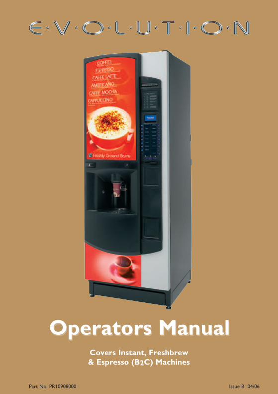
Operators ManualOperators ManualCovers Instant, Freshbrew& Espresso (B2C) Machines


Contents
Page No.
Introduction ...................................................................................................2
Important Safeguards ...................................................................................2
Section 1 - Machine Specifications............................................................3
Section 2 - Installation Procedure ............................................................7
Section 3 - How To Vend A Drink .......................................................14
Section 4 - Daily Cleaning and Re-filling...............................................20
Section 5 - Service Keypad Functions ...................................................32
Section 6 - Programming Mode ..............................................................36
Section 7 - Operators Program..............................................................40
Section 8 - Dispense Pipe Lengths .........................................................62
Section 9 - Error Messages and Simple Problem Solving .................69
Section 10 - De-commissioning The Machine.....................................71
The following Symbol is used throughout this Operators Manual:
Safety First! Take care, risk of personal injury.
© Copyright 2006 Crane Merchandising Systems
Operators Manual
1

Introduction
This manual provides a guide to the installation, daily operation, basic cleaning andmaintenance tasks for the Evolution range of freestanding vending machines andindicates when the operator should call a qualified service engineer for assistance. It isrecommended that this equipment is serviced by a trained Service Technician.
It is the policy of Crane Merchandising Systems to continue developing its range ofequipment. The information presented within this document was correct at time ofpublication, is for information only and may be changed without prior notice.
Important Safeguards
When using or cleaning the machine, always have this manual available for quick andeasy reference and always follow these basic safety precautions:
1. Read all instructions before using the machine and ensure that anyone who willbe involved with the cleaning or refilling of the machine also reads the instructions.
2. Beware of Electricity: Certain operations during the cleaning and maintenanceprocedure require the machine to be connected to the electricity supply andswitched on. These routines must be carried out separately to all other operationsand only by trained personnel. Observation of safe working practices inaccordance with current regulations is necessary at all times.
Important! Unless specified, always disconnect the machine from theelectricity supply before cleaning and servicing.
3. The mains lead should never trail from the machine and should always be keptaway from hot surfaces and sharp edges.
4. Do not operate the machine if any part is damaged, e.g. mains lead, until it hasbeen checked by a qualified Service Technician.
5. Allow the machine to cool before handling or moving.
6. Never immerse the machine in water, or any other liquid and never clean it witha water jet.
7. If the machine should accidentally freeze up, call a Service Technician to check itbefore switching on.
8. Ensure that you are conversant with the most recent Health and Safety at Workand Electricity at Work Regulations.
This machine is for indoor use only and because it is a beverage machine, should besited in a clean, hygienic area.
Operators Manual
2
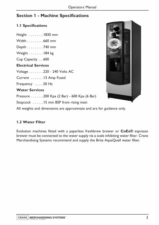
Section 1 - Machine Specifications
1.1 Specifications
Height . . . . . . . .1830 mm
Width . . . . . . . . .660 mm
Depth . . . . . . . . .740 mm
Weight . . . . . . . .184 kg
Cup Capacity . . .600
Electrical Services
Voltage . . . . . . . .220 - 240 Volts AC
Current . . . . . . .13 Amp Fused
Frequency . . . . .50 Hz
Water Services
Pressure . . . . . . .200 Kpa (2 Bar) - 600 Kpa (6 Bar)
Stopcock . . . . . .15 mm BSP from rising main
All weights and dimensions are approximate and are for guidance only.
1.2 Water Filter
Evolution machines fitted with a paperless freshbrew brewer or CoEx® espressobrewer must be connected to the water supply via a scale inhibiting water filter. CraneMerchandising Systems recommend and supply the Brita AquaQuell water filter.
Operators Manual
3

1.3 External Features
Key:
Operators Manual
4
1. Instruction Decal2. LCD Display3. Selection Decals (Build A Drink)4. Drink Selection Keypad5. Coin Reject Button6. Coin Entry7. Coin Return
8. Foot9. Door10. SureVend™ Sensor11. Door Lock12. Jug/Free Vend Switch13. Graphic Panel

1.4 Internal Features
Key:
Operators Manual
5
1. Service Keypad2. Cup Turret3. Cup Drop Unit4. Door Locking Mechanism5. Cup Catcher6. SureVend™ Sensors7. Drip Tray8. Kickplate9. Waste Bucket
10. Brewer Waste Container11. Dispense Head12. Mixing Station13. CoEx® Brewer (B2C)14. Ingredient Canister15. Fresh Beans Canister (B2C)16. Door Switch
Operators Manual
6
Section 2 - Installation Procedure
Important! It is essential that personnel responsible for installing,commissioning and servicing the machine understand the following:
1. The installation and commissioning of the machine should only be carried out bytrained and authorised service engineers.
2. All water and electrical services must be correctly and safely connected.
3. All covers must be replaced correctly and securely and the machine left in a safecondition.
2.1 Locating the Machine
1. The machine is suitable for indoor use only, situated in an area with arecommended ambient temperature not below 10º C and not exceeding 30º C.The machine should be located near the appropriate water and electrical servicesas detailed in Specifications (page 3).
2. Prior to moving the machine to its location, ensure that there is sufficient accessspace available via passageways, stairs, lifts, etc.
3. To ensure adequate ventilation, 100 - 150 mm (4 - 6 inches) clearance must beallowed between the back of the cabinet and the wall.
4. Open the door using the key provided. Remove all transit packing, installation kitand the box containing the cup stack assembly from the machine. Check for visualsigns of damage which may have occurred during transit. If the machine is damagedor any parts are missing, you must contact the supplier immediately.
5. Using a 12 mm spanner, adjust the feet until the machine is levelled in both frontto back and side to side planes. Ensure that the door opens and closes easily.
2.2 Connecting the Water Supply
1. The machine should be situated within 1 metre of a drinking water supply froma rising main, terminating with a W.R.C. approved 15mm compression stop-tap.
N.B. The water supply should comply with both the Statutory InstrumentNo.1147 - “Water, England and Wales” and The Water Supply (Water Quality)Regulations 1989. Water pressure at the stop-tap must be within the limits 2 - 6Bar (200 Kpa - 600 Kpa).
Operators Manual
7

2. Freshbrew & Espresso Machines: Evolution machines fitted with a paperlessfreshbrew brewer or CoEx® brewer must be connected to the water supply viaa water filter. This filter must be of food grade quality and able to removetemporary hardness (scale), heavy metals (lead, copper, iron, cadmium), chlorineand any organic pollutant’s/discolouration. Crane MerchandisingSystems recommend and supply the Brita AquaQuell waterfilter.
Warning! If the machines indicated above are connected to the water supplyand used without a water filter as specified, the warranty will be void.
3. Connect the flexi-hose supplied with the machine to the stopcock ensuring thatthe seal supplied is fitted correctly. Flush the system (several gallons) beforeconnecting the machine.
3. Connect the hose to the inlet valve located on the rear of the machine. Ensurethat the seal is correctly fitted. Ensure that all water supply fittings are tight.
4. Turn on the water supply at the stop tap and check for leaks. Prime the waterfilter (where fitted) following the instructions supplied by the filter manufacturer.
2.3 Connecting the Electrical Supply
Safety First! The machine must be earthed. On no account should it beearthed only to the water supply pipe.
The machine must be connected to a 230 Volt 50Hz 13 amp fused switched socketoutlet, installed to the latest edition of the IEE regulations, using a 3 pin BS approved13 amp fused plug.
Important: If the mains lead becomes damaged in any way it must be replaced by aspecial lead available from the manufacturer.
2.4 Commissioning Procedure
The following procedure must be carried out by a trained installation engineer beforethe machine can be used for the first time. Ensure that the electrical and water servicesto the machine are connected correctly. Check for leaks in the water supply.
1. Open the front door of the machine. Fit the door switch bracket to the door usingthe two screws provided. Ensure that the bracket will operate the door switchwhen the door is closed. Switch on the electricity supply.
2. Ensure that the waste bucket is fitted correctly. Clip the level detector andoverflow pipes correctly onto the rim of the bucket.
Operators Manual
8

3. Cup Turret. Release the catch securing the cup drop unitand swing the unit away from the door. Remove the cupstack assembly from its packaging and carefully place it ontothe cup drop unit. Ensure that the flat on the turret driveshaft locates with the flat in the cup turret mounting block.Remove the lid and fill the tubes with the correct size cupsfor the type of cup catcher fitted to the machine. Allow thecups to drop into the tubes directly from the packaging. DO NOT touch the cupswith your hands.
Important: Do not fill the tube directly above the cup dispense position. Allowthe cup turret motor to rotate a full tube to the cup dispense position when themachine is powered up. Rotating the cup turret by hand will damage themechanism.
Note: If paper cups are being loaded, each pack of cups must first be inspectedfor damage to the cup rims. Damaged cups must not be used.
4. Insert the safety key (a) supplied with the machine into thedoor switch as shown. The machine is now on. The cupturret mechanism will index the first available full cup stackto the dispense position and drop the cup stack into the cupdrop mechanism. Fill the remaining empty cup stack withcups and replace the lid.
5. Swing the cup turret assembly back to its operating position. Ensure that the unitis held securely by the catch.
6. All Models: The water inlet valve will open andthe heater tank will start to fill. As the waterheats, ensure that no water overflows from theheater tank overflow pipe into the waste bucket.When the machine has powered up, the LCDwill display the message as shown opposite.Check the system for leaks.
Note! The machine has a safety cut-out which will only allow the heater tank tofill for a maximum of two minutes. If after software power-up the heater tank hasnot filled within this time, the mains power supply should be switched off and thenon again to reset the heater tank time-out.
Espresso Models: As the machine initialises a small amount of water is pumpedthrough the system and is discharged into the waste bucket. When the machineenters standby mode remove the bucket and empty the contents before refittingto the machine.
Operators Manual
9
a

N.B. Before using the espresso machine for the first time itis necessary to purge the water system to ensure any waterleft in the system during transport is dispensed. Press button9 on the Service Keypad fitted inside the door (photo). Themachine will pump approximately 400ml of water throughthe system which will be heated to operating temperaturebefore being discharged into the waste bucket. When themachine enters standby mode remove the bucket and empty the contents beforerefitting to the machine.
Important: Should the machine fail to fill correctly or leak, turn off thestopcock and the power to the machine before investigating the fault.
7. Check the LCD display on the front of the machine to ensure that the water hasheated to the correct temperature and that the machine is in standby mode. Amachine set to free vend mode will alternate the messages:
N.B. Messages displayed in standby mode will change depending upon themonetary device fitted and set up during programming.
8. All Models: Rotate soluble/freshbrew ingredient canister outlets to uprightposition.
Remove the milk canister from the machine and remove thelid. Place the canister into the canister filling station locatedon the door (photo) and fill canister with correct ingredient.
DO NOT place the canister on the floor or overfill withingredient.
Carefully remove the canister from the filling station andreplace the lid. Refit canister into machine ensuring that it isreturned to correct operating station.
Repeat this operation for all soluble/freshbrew ingredient canisters fitted to themachine. Rotate the canister outlets to their correct operating positions.
9. Espresso Models: Close the outlet slide to seal the fresh beans canister outletbefore removing the canister from the machine. Remove the canister lid.
Operators Manual
10

To aid filling, hang the fresh beans canister on the rear ofthe door utilising the two keyhole slots provided. DO NOTplace the canister on the floor.
Fill the canister with fresh coffee beans. The canister has acapacity of approximately 3.5 kgs. Refit the canister lid andcarefully remove the canister from the door. Refit thecanister into the machine, ensuring that it is locatedcorrectly. Open the outlet slide to ensure correct operation.
N.B. To maintain optimum drink quality, Crane Merchandising Systemsrecommend that the bean canister is replenished on a daily basis.
10. Press the Cup Test switch (7), located in the Service Keypad on the rear of thedoor and ensure that a cup is ejected cleanly from the cup drop unit.
11. Press the Park Head switch (8), located in the Service Keypad on the rear ofthe door and ensure that the dispense head moves to its fully extended position.Press the switch again to return the dispense head to its correct (homed) position.
12. Freshbrew Models: Ensure the brewer guard and brewer waste container arefitted correctly. Slide the container into position directly under the brewer withits lip outside the brewer cover.
(Freshbrew models fitted with paper fed brewer only - proceed withsteps 13 - 15)
13. Load the filter paper roll (provided in the installation kit) onto the support.
14. Press and hold the Brewer Open switch (2) on the service keypad until thebrewer chamber reaches its fully open position. Remove the safety key to switchoff the power to the machine.
15. Remove the brewer cover and paper/waste ingredient guard. Feed the filter paperunder the raised chamber and through the feed wheels.
Refit the guard and brewer cover. Insert the safety key into the door switch. Thebrewer will index to its closed position and stop.
16. Espresso Models: Ensure that the brewer waste container is fitted correctlybeneath the CoEx® brewer unit and tea brewer unit (if fitted).
Operators Manual
11
17. Referring to Sections 6 & 7 of this manual, Programming Mode andOperators Program, use the menu selections available to programme therequired settings for correct machine operation e.g. drink prices, disableselections, time and date etc.
18. If fitted, check that the coin mechanism and cash boxoperate correctly. Release the catch securing the coinmechanism cover (photo) and swing the cover away fromthe door. Fill the coin tubes with correct coinage. Ensurecoin return mechanism functions correctly.
19. Operate the machine through its complete range of selections to ensure that eachvend is correctly dispensed. Follow the instructions detailed on page 34 for makinga vend using the Test Vend switch (6) located on the Service Keypad.
20. Remove the safety key and close the cabinet door. Ensure that the machine is leftin a clean and safe condition.
2.5 Setting Up The Carbonator Unit - Where Fitted
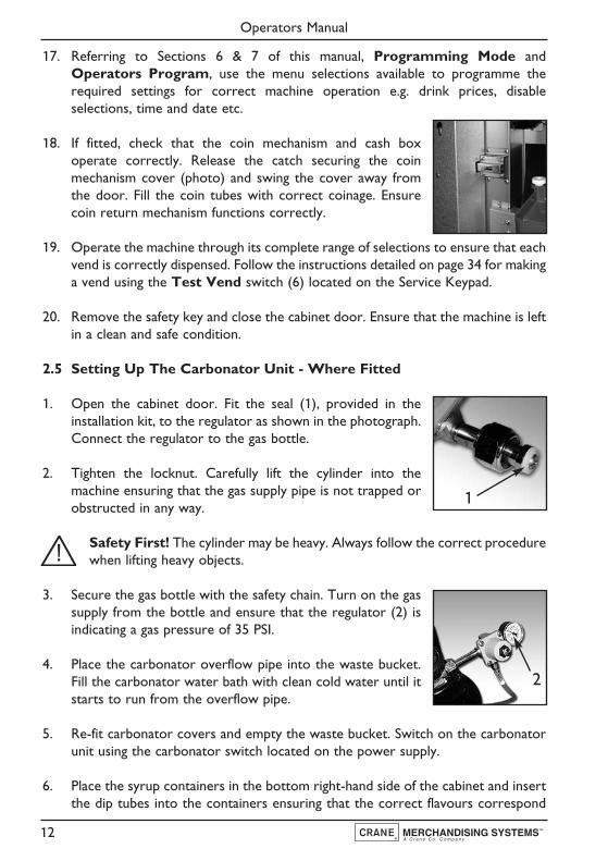
1. Open the cabinet door. Fit the seal (1), provided in theinstallation kit, to the regulator as shown in the photograph.Connect the regulator to the gas bottle.
2. Tighten the locknut. Carefully lift the cylinder into themachine ensuring that the gas supply pipe is not trapped orobstructed in any way.
Safety First! The cylinder may be heavy. Always follow the correct procedurewhen lifting heavy objects.
3. Secure the gas bottle with the safety chain. Turn on the gassupply from the bottle and ensure that the regulator (2) isindicating a gas pressure of 35 PSI.
4. Place the carbonator overflow pipe into the waste bucket.Fill the carbonator water bath with clean cold water until itstarts to run from the overflow pipe.
5. Re-fit carbonator covers and empty the waste bucket. Switch on the carbonatorunit using the carbonator switch located on the power supply.
6. Place the syrup containers in the bottom right-hand side of the cabinet and insertthe dip tubes into the containers ensuring that the correct flavours correspond
Operators Manual
12
1
2
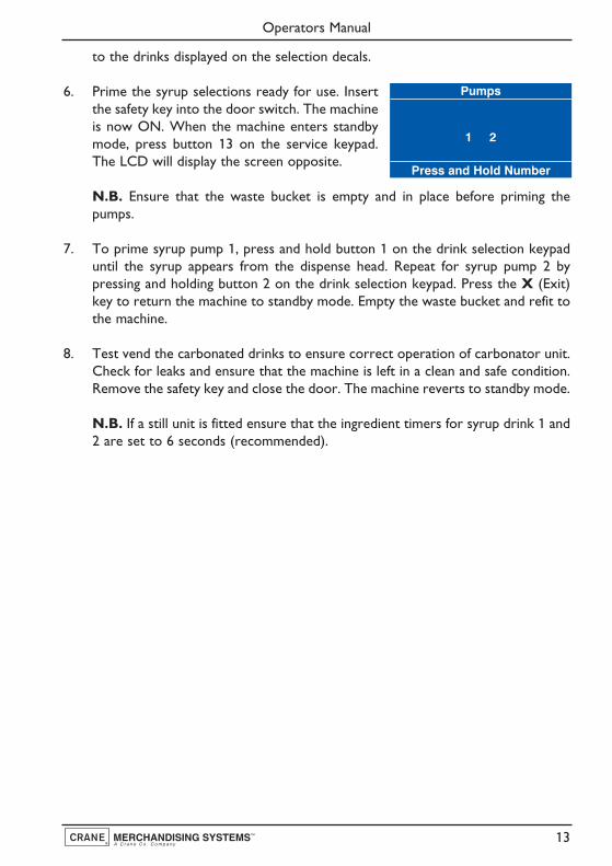
to the drinks displayed on the selection decals.
6. Prime the syrup selections ready for use. Insertthe safety key into the door switch. The machineis now ON. When the machine enters standbymode, press button 13 on the service keypad.The LCD will display the screen opposite.
N.B. Ensure that the waste bucket is empty and in place before priming thepumps.
7. To prime syrup pump 1, press and hold button 1 on the drink selection keypaduntil the syrup appears from the dispense head. Repeat for syrup pump 2 bypressing and holding button 2 on the drink selection keypad. Press the X (Exit)key to return the machine to standby mode. Empty the waste bucket and refit tothe machine.
8. Test vend the carbonated drinks to ensure correct operation of carbonator unit.Check for leaks and ensure that the machine is left in a clean and safe condition.Remove the safety key and close the door. The machine reverts to standby mode.
N.B. If a still unit is fitted ensure that the ingredient timers for syrup drink 1 and2 are set to 6 seconds (recommended).
Operators Manual
13
Pumps
Press and Hold Number
1 2
Section 3 - How To Vend A Drink
Evolution machines are available with either a numeric keypad or an intuitive build adrink interface. Both selection methods allow the user to produce a drink to theirpreferred taste and strength.
3.1 Selecting A Drink - Numeric Keypad
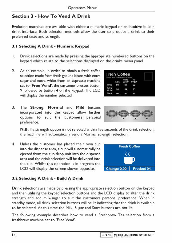
1. Drink selections are made by pressing the appropriate numbered buttons on thekeypad which relate to the selections displayed on the drinks menu panel.
2. As an example, in order to obtain a fresh coffeeselection made from fresh ground beans with extrasugar and extra white from an espresso machineset to ‘Free Vend’, the customer presses button9 followed by button 4 on the keypad. The LCDwill display the number selected.
3. The Strong, Normal and Mild buttonsincorporated into the keypad allow furtheroptions to suit the customers personalpreference.
N.B. If a strength option is not selected within five seconds of the drink selection,the machine will automatically vend a Normal strength selection.
4. Unless the customer has placed their own cupinto the dispense area, a cup will automatically beejected from the cup drop unit into the dispensearea and the drink selection will be delivered intothe cup. Whilst this operation is in progress theLCD will display the screen shown opposite.
3.2 Selecting A Drink - Build A Drink
Drink selections are made by pressing the appropriate selection button on the keypadand then utilising the keypad selection buttons and the LCD display to alter the drinkstrength and add milk/sugar to suit the customers personal preference. When instandby mode, all drink selection buttons will be lit indicating that the drink is availableto be selected. At this time the Milk, Sugar and Start buttons are not lit.
The following example describes how to vend a Freshbrew Tea selection from afreshbrew machine set to ‘Free Vend’.
Operators Manual
14
Fresh Coffee
Product 94Change 0.00

1. Press selection button 3, Freshbrew Tea onthe keypad. All of the other selections buttonswill be extinguished, the Milk, Sugar and Startbuttons will light up and the machine exits fromstandby mode. The LCD will display the screenas shown opposite.
N.B. The default strength setting for this drink selection is Normal as shown.
2. To obtain a Strong or Mild beverage it is necessary to press the current drinkselection button. Pressing once will toggle to the Strong selection. Pressing thebutton again will toggle to the Mild selection.
Pressing the current drink selection button again will revert to the Normal screen.
3. If milk and/or sugar is required, it is necessary topress the corresponding button on the keypadfor each selection. When the Milk button ispressed the LCD changes and displays the defaultscreen as shown opposite.
4. If Extra Milk is required the customer presses the milk button a second time. Athird press will display the No Milk selection.
Pressing the milk button again will revert to the Milk selection.
5. If the customer requires sugar it is necessary topress the sugar button. The LCD changes anddisplays the default screen shown opposite.
Operators Manual
15
Freshbrew Tea(Press again for strength)
(Press Milk / Sugar / Start)
Mild StrongNormal
Credit .00 10.30 AM
Freshbrew Tea(Press again for strength)
(Press Milk / Sugar / Start)
Mild StrongNormal
Credit .00 10.30 AM
Freshbrew Tea(Press again for strength)
(Press Milk / Sugar / Start)
Mild StrongNormal
Credit .00 10.30 AM
Press currentdrink key to
increment strength
Freshbrew Tea
Credit .00 10.31 AM
Extra Milk
No Milk
Milk
Freshbrew Tea
Credit .00 10.31 AM
Extra Sugar
No Sugar
Sugar
Press milk key toincrement strength
Freshbrew Tea
10.31 AM
Extra Milk
No Milk
Milk
Freshbrew Tea
10.31 AM
Extra Milk
No Milk
Milk
Credit .00 Credit .00
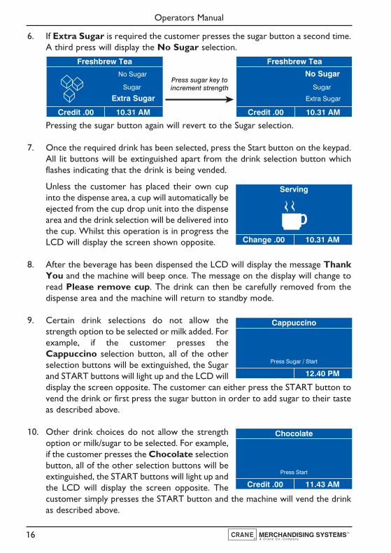
6. If Extra Sugar is required the customer presses the sugar button a second time.A third press will display the No Sugar selection.
Pressing the sugar button again will revert to the Sugar selection.
7. Once the required drink has been selected, press the Start button on the keypad.All lit buttons will be extinguished apart from the drink selection button whichflashes indicating that the drink is being vended.
Unless the customer has placed their own cupinto the dispense area, a cup will automatically beejected from the cup drop unit into the dispensearea and the drink selection will be delivered intothe cup. Whilst this operation is in progress theLCD will display the screen shown opposite.
8. After the beverage has been dispensed the LCD will display the message ThankYou and the machine will beep once. The message on the display will change toread Please remove cup. The drink can then be carefully removed from thedispense area and the machine will return to standby mode.
9. Certain drink selections do not allow thestrength option to be selected or milk added. Forexample, if the customer presses theCappuccino selection button, all of the otherselection buttons will be extinguished, the Sugarand START buttons will light up and the LCD willdisplay the screen opposite. The customer can either press the START button tovend the drink or first press the sugar button in order to add sugar to their tasteas described above.
10. Other drink choices do not allow the strengthoption or milk/sugar to be selected. For example,if the customer presses the Chocolate selectionbutton, all of the other selection buttons will beextinguished, the START buttons will light up andthe LCD will display the screen opposite. Thecustomer simply presses the START button and the machine will vend the drinkas described above.
Operators Manual
16
Serving
10.31 AMChange .00
Press sugar key toincrement strength
Freshbrew Tea
Credit .00 10.31 AM
Extra Sugar
No Sugar
Sugar
Freshbrew Tea
Credit .00 10.31 AM
Extra Sugar
No Sugar
Sugar
Cappuccino
Press Sugar / Start
12.40 PM
Chocolate
Press Start
11.43 AMCredit .00

3.3 Selecting A Drink - Cold Drink Selections
Evolution machines may be fitted with either a chiller or carbonator unit allowing coldwater and flavoured drinks to be vended, either still or both still and sparkling.
The following example describes how to vend a cold flavoured drink from an Evolutionmachine fitted with a carbonator unit.
1. Press the selection button for the cold flavoureddrink required on the keypad. All of the otherdrink selection buttons will be extinguished, theSTART button will light up and the machine exitsfrom standby mode. The LCD will display thescreen as shown opposite.
N.B. The default setting for cold drink selections is Still as shown.
2. To obtain a Sparkling drink press the current drink selection button. Pressing thebutton again will revert back to the Still setting.
3. Once the drink has been selected, press the START button on the keypad. Thedrink selection button will flash indicating that the drink is being vended. Unlessthe customer has placed their own cup into the dispense area, a cup willautomatically be ejected from the cup drop unit into the dispense area and thedrink selection will be delivered into the cup. Whilst this operation is in progressthe LCD will display the “Serving” screen
4. After the cold drink has been dispensed the LCD will display the message ThankYou and the machine will beep once. The message on the display will change toread Please remove cup. The drink can then be removed from the dispense areaand the machine will return to standby mode.
Operators Manual
17
Cold Drink 1 (Still)
(Press Start)
01.50Credit 0.00

3.4 Replacing/Updating Drink Selection Decals
1. Numeric Keypad Models
Self adhesive drink selection and pricing decals are mounted onto a decal carrierlocated behind the main graphic panel. To update drink pricing or replace drinkdescription decals, proceed as follows:
1. Open the front door of the machine. Supporting thetransparent graphic cover with your right hand, carefully undoand remove the three knurled thumb screws from the rearof the door which secure the graphic cover support strip.
2. Carefully remove the support strip, transparent graphiccover, printed graphic and decal carrier from the machine.Place the decal carrier face-up on a clean, flat surface.
3. Updating drink pricing: Carefully remove the previous price decals from thedrink selection decals. Update the prices where necessary using new self adhesivedecals. These are available as spares from the manufacturer.
4. Updating drink selections and pricing: When updating selection decals andprices it may be necessary to use a new decal carrier. These are available as sparesfrom the manufacturer - part no. PR11227000.
Peel the relevant drink selection decals from their backing sheet and apply to thedecal carrier using the printed guides.
Important: Ensure that drink selections and numbering used relate to drinkchoices programmed into the machine software.
Apply price decals as described above.
5. Place the decal carrier behind the printed graphic ensuring that the drinkselections are visible through the pre-cut viewing area. Refit the decal carrier,graphic, transparent cover and graphic support strip to the door. Ensure that thetransparent cover is correctly located in the fixed support strip before securingthe removable support strip with the three knurled thumb screws.
6. Close the front door and ensure that the machine returns to standby mode.
Operators Manual
18

2. Build A Drink Models
Self adhesive drink selection and pricing decals are mounted onto a paper backing sheetwhich is secured behind a transparent clip-in cover. To update drink pricing or replacedrink description decals, proceed as follows:
1. Open the front door of the machine. Release the catch securing the coinmechanism cover and swing the cover to its open position.
2. Carefully remove the main controller board cover. Loosen the two screws abovethe keyhole slots which secure the cover and lift the cover out of the machine.
3. Referring to the photograph, carefully press down the snapfit clip (a) to release the transparent decal cover.
Remove the transparent cover and decal sheet from thedoor moulding. Place the decal sheet face-up on a clean, flatsurface.
4. Updating pricing: Carefully remove the previous price decals from the drinkselection decals. Update the prices where necessary using new self adhesive decalsThese are available as spares from the manufacturer.
5. Updating drink selections and pricing: When updating selection decals andprices it will be necessary to use a new backing sheet. These are available as sparesfrom the manufacturer.
Peel the relevant drink selection decals from their backingsheet (part no. PR10233000 & PR10918000) and apply to thebacking sheet using the printed guides as shown opposite.
Important: Ensure that drink selections used relate to drinkchoices programmed into the machine software.
Apply price decals as described above.
6. Place the decal carrier behind the transparent decal cover and refit completeassembly to the door. Ensure decal cover locating lugs are correctly locatedbefore pushing the snap fit clip into place.
7. Replace the main controller board cover and tighten the screws to secure. Closethe coin mechanism cover ensuring that the catch is secured correctly. Close thefront door and ensure that the machine returns to standby mode.
Operators Manual
19
a

Section 4 - Daily Cleaning And Re-filling
The quality of drinks produced by the Evolution can only be maintained if the machineis cleaned regularly following the schedule outlined. Before carrying out the dailycleaning procedure described on the following pages, it is recommended that you havethe following materials to hand:
● Bactericidal Cleaner● De-Staining Agent● Cleaning Cloths● Paper Towels● Small Brush● Two Large Buckets● Disposable Gloves● CoEx® Cleaning Tablets (Espresso Machines)
4.1 Bactericidal Cleaner
This can either be a liquid or powder agent which should be dissolved in clean waterin accordance with the instructions on the product packaging. The solution should beused for cleaning machine components and wiping surfaces during the cleaningoperation.
4.2 De-Staining Agent
This is a liquid or powder agent which should be dissolved in clean water in accordancewith the instructions on the product packaging. The solution can be used on heavilysoiled or stained components such as buckets and drip trays. Items or surfaces cleanedwith this solution must be rinsed in clean water to remove traces of the cleaning agent.
4.3 Liquid Destainer - Brewer Units
Crane Merchandising Systems recommends that a liquid destaining product is used forcleaning the paper/paperless brewer units fitted to Evolution freshbrew machines. Theproduct must be used in accordance with the instructions on the product packaging,following all health and safety guidelines. A detailed procedure for cleaning the brewerunits is outlined on pages 25 - 28 of this Operators Manual.
4.4 Cleaning Tablets - CoEx® Brewer Units (Espresso Models)
Crane Merchandising Systems recommends that the brewer cleaning tablets suppliedwith the machine are used exclusively for cleaning the CoEx® brewer fitted toEvolution espresso machines. These are available from your machine supplier in packsof 30 - part number ZC10598000. A detailed procedure for cleaning the CoEx®brewer unit is outlined on pages 28 - 30 of this Operators Manual.
Operators Manual
20
Important: It is necessary to carry out the cleaning and maintenance procedureoutlined on the following pages on a regular basis, either at the end of the day or atthe start of the day before the machine is in constant use.
4.5 Cleaning & Filling Procedure - All Machines
1. Fill a cleaning bucket with hot water and dilute the bactericidal cleaner inaccordance with the instructions on the product packaging. Open the door of themachine.
2. Rotate canister outlets to upright position. Removethe ingredient canisters. DO NOT place them on thefloor.
With a clean, damp sanitised cloth, remove anyingredient build up on the exterior of the canisters,paying particular attention to the area around thecanister outlets. Ensure canister outlets are driedthoroughly after cleaning.
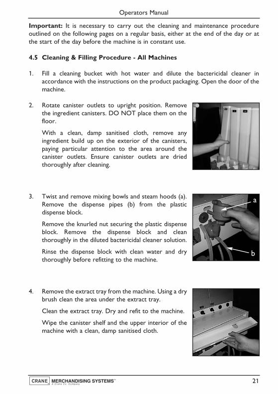
3. Twist and remove mixing bowls and steam hoods (a).Remove the dispense pipes (b) from the plasticdispense block.
Remove the knurled nut securing the plastic dispenseblock. Remove the dispense block and cleanthoroughly in the diluted bactericidal cleaner solution.
Rinse the dispense block with clean water and drythoroughly before refitting to the machine.
4. Remove the extract tray from the machine. Using a drybrush clean the area under the extract tray.
Clean the extract tray. Dry and refit to the machine.
Wipe the canister shelf and the upper interior of themachine with a clean, damp sanitised cloth.
Operators Manual
21
a
b
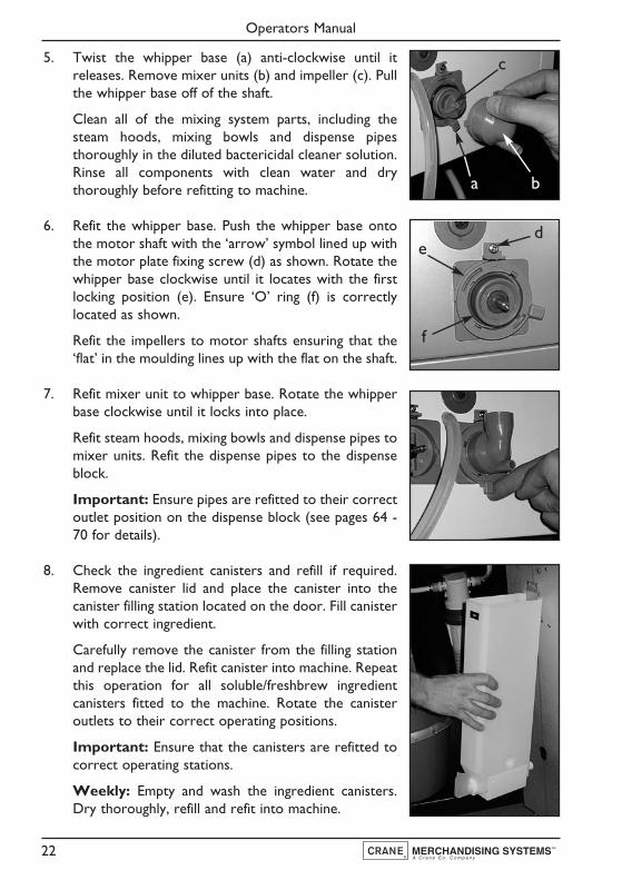
5. Twist the whipper base (a) anti-clockwise until itreleases. Remove mixer units (b) and impeller (c). Pullthe whipper base off of the shaft.
Clean all of the mixing system parts, including thesteam hoods, mixing bowls and dispense pipesthoroughly in the diluted bactericidal cleaner solution.Rinse all components with clean water and drythoroughly before refitting to machine.
6. Refit the whipper base. Push the whipper base ontothe motor shaft with the ‘arrow’ symbol lined up withthe motor plate fixing screw (d) as shown. Rotate thewhipper base clockwise until it locates with the firstlocking position (e). Ensure ‘O’ ring (f) is correctlylocated as shown.
Refit the impellers to motor shafts ensuring that the‘flat’ in the moulding lines up with the flat on the shaft.
7. Refit mixer unit to whipper base. Rotate the whipperbase clockwise until it locks into place.
Refit steam hoods, mixing bowls and dispense pipes tomixer units. Refit the dispense pipes to the dispenseblock.
Important: Ensure pipes are refitted to their correctoutlet position on the dispense block (see pages 64 -70 for details).
8. Check the ingredient canisters and refill if required.Remove canister lid and place the canister into thecanister filling station located on the door. Fill canisterwith correct ingredient.
Carefully remove the canister from the filling stationand replace the lid. Refit canister into machine. Repeatthis operation for all soluble/freshbrew ingredientcanisters fitted to the machine. Rotate the canisteroutlets to their correct operating positions.
Important: Ensure that the canisters are refitted tocorrect operating stations.
Weekly: Empty and wash the ingredient canisters.Dry thoroughly, refill and refit into machine.
Operators Manual
22
ba
c
de
f

9. Espresso Models: If necessary refill the fresh coffeebeans canister. Close the outlet slide (a) to seal thecanister exit before removing the canister from themodule.
Remove the canister lid. To aid filling, hang the canisteron the rear of the door utilising the keyhole slotsprovided. DO NOT place the canister on the floor.Refill canister with fresh coffee beans.
Refit the canister lid to the canister. Refit canister to the module. Ensure that theoutlet slide is opened to ensure correct operation.
N.B. To maintain optimum drink quality, Crane Merchandising Systemsrecommend that the bean container is replenished on a daily basis.
10. Remove the waste water bucket from the machine.Empty and clean.
If fitted, check the syrup levels in the syrup containersand replace if necessary.
Clean the base, sides and back of the machine.
Refit the waste water bucket into the machine. Ensurethat the level detector and overflow pipes are locatedcorrectly in the bucket.
11. Undo the knurled nuts and remove the cup throatmoulding complete with drain pipe.
Clean cup throat and pipe in the sanitiser solution.Rinse both components with clean water and drythoroughly.
Reassemble to the machine.
12. Pull out the two spring loaded pins (a) securing thedrip tray and turn to lock as shown. Pull and removethe complete drip tray assembly out of its mountingbracket.
Wash the tray and grille thoroughly and wherenecessary, sanitise using the diluted bactericidal cleanersolution.
Operators Manual
23
a
a
13. Wipe clean the interior of the door and the areaaround the cup station using a clean, damp sanitisedcloth.
Refit the drip tray ensuring that the drip tube from thecup throat moulding is located correctly at the rear ofthe tray.
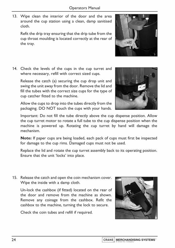
14. Check the levels of the cups in the cup turret andwhere necessary, refill with correct sized cups.
Release the catch (a) securing the cup drop unit andswing the unit away from the door. Remove the lid andfill the tubes with the correct size cups for the type ofcup catcher fitted to the machine.
Allow the cups to drop into the tubes directly from thepackaging. DO NOT touch the cups with your hands.
Important: Do not fill the tube directly above the cup dispense position. Allowthe cup turret motor to rotate a full tube to the cup dispense position when themachine is powered up. Rotating the cup turret by hand will damage themechanism.
Note: If paper cups are being loaded, each pack of cups must first be inspectedfor damage to the cup rims. Damaged cups must not be used.
Replace the lid and rotate the cup turret assembly back to its operating position.Ensure that the unit ‘locks’ into place.
15. Release the catch and open the coin mechanism cover.Wipe the inside with a damp cloth.
Un-lock the cashbox (if fitted) located on the rear ofthe door and remove from the machine as shown.Remove any coinage from the cashbox. Refit thecashbox to the machine, turning the lock to secure.
Check the coin tubes and refill if required.
Operators Manual
24

16. Insert the safety key supplied with the machine into thedoor switch. The machine is now on.
Using the service keypad located in the rear of thedoor (photo), proceed as follows:
a. Press the Cup Test switch (7) and check that acup is ejected correctly from the Cup drop unit.
b. Press the Park Head switch (8) to ensure that thedispense head operates correctly and that thedispense pipes are fitted correctly.
c. Place a suitable container under the dispense head and press the Rinse/Flushswitch (3). The machine will flush the system. Check that all of the mixingstations are water tight. Empty the contents of the container.
d. Place an empty cup under the dispense head. Press the Test Vend switch (6)and using the selection buttons on the front of the machine, vend a drink toensure that the machine operates correctly. Press the ‘X’ (Exit) key to exitfrom the Test Vend menu.
e. Press the View Counters switch (5) and record the audit informationdisplayed on the LCD (see page 33 for full details).
Remove the safety key and close the door. Clean and buff the outside of themachine.
4.6 Paper Type (King) Freshbrew Brewer Cleaning Procedure
At least twice a week the paper type brewer unit must be removed from Evolutionfreshbrew machines and cleaned.
Safety First! Never clean or service the brewer unit while it is in motion asfingers may become trapped in the mechanism.
1. Open the front door of the machine and remove the paper/waste ingredientguard. Switch on the power using the door switch safety key.
2. Press and hold the Brewer Open switch (2) located inthe service keypad on the rear of the door to indexthe brewer to its fully open position.
When the brewer reaches its fully open position,remove the safety key to switch off the power. Tearthe filter paper above the brewer (a). Remove the usedpaper from the brewer unit.
Operators Manual
25
a

3. Remove the brewer dispense pipe from the dispensehead. Pull down the brewer release pin (b) andcarefully lift the brewer unit up and clear of its locatingbracket.Thoroughly clean the external surfaces of thebrewer.
4. With the brewer unit removed, clean the areasurrounding its locating bracket. Refit brewer tomachine and refit the outlet pipe to the dispense head.
5. Switch on the power to the machine using the safety key. The brewer chamberwill return to its closed position. Referring to the instructions supplied with theproduct, pour the recommended amount of de-staining fluid directly into the topof the brewer chamber. Flush the brewer using the Brewer Clean switch (4)following the procedure outlined on page 33.
6. Press and hold the Brewer Open switch (2) to index the brewer to its fully openposition. Remove the safety key to switch off the power to the machine. Feed thefilter paper through the paper feed mechanism. Switch on the power to themachine using the safety key. Filter paper will index automatically and the brewerchamber will return to its closed position. Refit the brewer guard.
7. Remove the brewer waste container and empty its contents. Clean waste bucketand refit into machine. Remove the safety key and close the door.
N.B. Every time that the brewer waste container is emptied the waste countermust be reset. Restore power to the machine using the safety key and pressbutton 12 on the service keypad. Two audible bleeps confirm that the counterhas been reset to zero.
4.7 Paperless Brewer Unit - Cleaning Procedure
1. Switch on the power using the door switch safety key. Press and hold the BrewerOpen switch (2) located in the service keypad on the rear of the door until thebrewer chamber reaches its fully open position.
Remove the door switch safety key to switch off thepower to the machine. Remove the brewer guard.
2. Carefully remove the water outlet tubes c/w waterpipes (a) from the tea and coffee chambers. Lift thelatch bar (b) and remove the brewer chambers/wipearms assembly.
Operators Manual
26
b
b
a

3. Clean the brewer chambers/wipe arms assembly in the sanitiser solution. Rinsewith clean water and dry thoroughly.
4. Carefully slide the brewer chambers/wipe armsassembly into the brewer unit.
IMPORTANT: The wiper arm lug (a) must belocated between the stainless steel arms (b) asshown.
5. Re-assemble the water outlet tubes to the coffee andtea brewer chambers.
Using the clamp supplied, close the tea outlet tube asshown.
6. Switch on the power using the door switch safety key.The brewer chamber will automatically index to itsclosed position.
Ensure that a suitable container is placed under thedispense area.
Pour the recommended amount of destaining fluiddirectly into the top of both brewer chambers.
7. Remove the clamp from tea dispense pipe. Press the Brewer Clean switch (4)located in the service keypad on the rear of the door. The machine willautomatically flush through the brewer four times.
If necessary repeat the above instruction until all traces of cleaning fluid areremoved from the brewer chambers.
8. Remove the door switch safety key. Remove and empty the water wastecontainer. Refit the brewer guard.
Remove the brewer waste container from the machine. Empty the contents.Washthe waste container thoroughly and where necessary sanitise using the sanitisersolution. Dry using a clean cloth and refit into the machine.
Operators Manual
27
a
b
b

N.B. Every time that the brewer waste container is emptied the waste countermust be reset. Restore power to the machine using the safety key and pressbutton 12 on the service keypad. Two audible bleeps confirm that the counterhas been reset to zero.
Close and lock the door.
4.8 CoEx® Espresso Brewer Unit - Daily Cleaning Procedure
1. Remove the coffee dispense pipe from the breweroutlet. Holding the unit as shown in the photograph,lift the green lever (a) and carefully pull the brewer unitout of the machine.
Fill a cleaning bucket with hot water and dilute thebactericidal cleaning agent in accordance with theinstructions on the product packaging.
2. Carefully place the CoEx® brewer unit into the dilutedbactericidal solution and clean the unit thoroughly.Ensure all coffee ground deposits are removed, payingparticular attention to the area around the top of thepiston and waste chute.
Remove the unit from the solution and rinsethoroughly with clean water. Dry the unit using a cleancloth or paper towels.
3. Remove the espresso coffee chute assembly (a).Unscrew the two knurled thumbscrews (b) andremove the coffee chute and coffee chute cover.
With a clean, dry brush clean the area around andunder the coffee dispense outlets.
4. With a clean, dry brush wipe away any coffee depositsfrom both the coffee chute and cover mouldings.
Refit the coffee chute lid to the chute ensuring that thelugs on the cover fit securely into their mounting holes.
Refit the assembly to the machine and secure using thetwo knurled thumbscrews.
Operators Manual
28
b
a

5. Carefully remove the brewer waste container fromthe machine and empty the contents. Push up andremove the waste chute (a) from the machine.
Wash both the waste container and chute thoroughlyand if necessary sanitise using the diluted bactericidalcleaning solution. Rinse in clean water.
Dry both components using a clean, dry cloth and refitto the machine.
N.B. Every time that the brewer waste container is emptied the waste countermust be reset. Restore power to the machine using the safety key and pressbutton 12 on the service keypad. Two audible bleeps confirm that the counterhas been reset to zero.
6. Refit the CoEx® brewer unit into the machine. Slidethe unit into place until it ‘clicks’ into position. Refit thecoffee dispense pipe to the brewer outlet as shown.
Ensure that both the fresh bean container and freshground coffee canister are filled with correct product.Refill if necessary following the procedures outlined onpages 22 and 23.
4.9 CoEx® Espresso Brewer Unit - Weekly Cleaning Procedure
The following procedure must be carried out on a weekly basis. Proceed as follows:-
1. Open the front door of the machine and insert the safety key to restore powerto the machine.
Caution: Ensure that a suitable container is placed under the dispenseposition. Keep hands away from the dispense area whilst the cleaning cycle isin operation.
2. Press and release button 11 on the service keypad. TheLCD will display the message ‘Please PlaceCleaning Tablet in Brewer’.
Take one cleaning tablet (supplied in packs of 30 - CMSpart no. ZC10598000) and place it into the brewerpiston chamber as shown.
Operators Manual
29
a

3. Press the START/? key on the drink selection keypad to begin the CoEx® tabletcleaning routine.
4. The cleaning cycle lasts approximately 7 minutes and dispenses 850 ml of waterthrough the dispense head. The LCD will display the message ‘Cleaning inProgress’ throughout the cleaning cycle.
Safety First! Keep hands clear of the brewer mechanism during the cleaningroutine.
5. When the cleaning cycle is complete the LCD will display the message ‘CleaningCycle Complete’. Press the X (Exit) key on the drink selection keypad to returnthe machine to standby mode. Empty the water from the container.
6. Remove the safety key and close the front door.
4.10 Tea Pot Brewer Cleaning Procedure
The following procedure must be carried out weekly. Proceed as follows:-
Safety First! Never clean or service the tea pot brewer unit while it is inmotion as fingers may become trapped in the mechanism.
1. Remove the tea outlet pipe from the dispense headblock. Lift and remove the mounting bracket c/w teapot bowl from the machine.
Split the assembly into its component parts. Clean allparts of the tea pot bowl assembly and mountingbracket using the liquid destaining agent.
Follow the instructions for soak cleaning on theproduct packaging. Rinse all components with cleanwater and dry thoroughly.
2. Undo the knurled thumb screw retaining the teabrewer unit.
Press down on the retaining clip and remove thecomplete tea brewer unit from the machine as shown.
Operators Manual
30
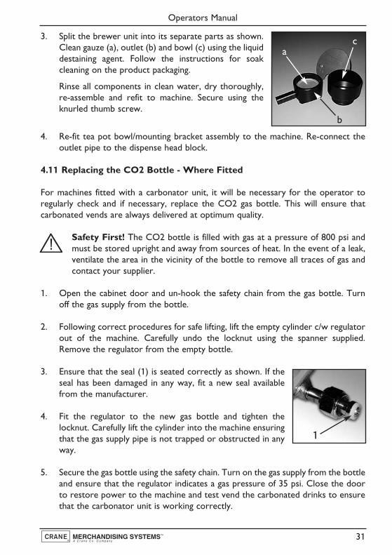
3. Split the brewer unit into its separate parts as shown.Clean gauze (a), outlet (b) and bowl (c) using the liquiddestaining agent. Follow the instructions for soakcleaning on the product packaging.
Rinse all components in clean water, dry thoroughly,re-assemble and refit to machine. Secure using theknurled thumb screw.
4. Re-fit tea pot bowl/mounting bracket assembly to the machine. Re-connect theoutlet pipe to the dispense head block.
4.11 Replacing the CO2 Bottle - Where Fitted
For machines fitted with a carbonator unit, it will be necessary for the operator toregularly check and if necessary, replace the CO2 gas bottle. This will ensure thatcarbonated vends are always delivered at optimum quality.
Safety First! The CO2 bottle is filled with gas at a pressure of 800 psi andmust be stored upright and away from sources of heat. In the event of a leak,ventilate the area in the vicinity of the bottle to remove all traces of gas andcontact your supplier.
1. Open the cabinet door and un-hook the safety chain from the gas bottle. Turnoff the gas supply from the bottle.
2. Following correct procedures for safe lifting, lift the empty cylinder c/w regulatorout of the machine. Carefully undo the locknut using the spanner supplied.Remove the regulator from the empty bottle.
3. Ensure that the seal (1) is seated correctly as shown. If theseal has been damaged in any way, fit a new seal availablefrom the manufacturer.
4. Fit the regulator to the new gas bottle and tighten thelocknut. Carefully lift the cylinder into the machine ensuringthat the gas supply pipe is not trapped or obstructed in anyway.
5. Secure the gas bottle using the safety chain. Turn on the gas supply from the bottleand ensure that the regulator indicates a gas pressure of 35 psi. Close the doorto restore power to the machine and test vend the carbonated drinks to ensurethat the carbonator unit is working correctly.
Operators Manual
31
ac
b
1

Section 5 - Service Keypad Functions
Evolution machines are fitted with a service keypadmounted on the rear of the door (photo). This keypadcontains the Operators Program entry key and also allowsthe operator to carry out specific functions during routinecleaning and maintenance.
N.B. During certain operations e.g. View Counters it isnecessary for the operator to utilise the selection keypadand LCD mounted on the front of the door to access data.Please refer to Section 6 - Programming Mode for details of selection keypad layoutsand functions.
When the safety key is inserted into the door switch and the machine is switched on,the service keypad allows the operator to carry out the following functions:
5.1 Switch 1 - Program Entry
This switch allows the operator to access the Operators Program (Section 7, page 40).
5.2 Switch 2 - Brewer Open (Freshbrew Models)
This switch operates the brewer fitted to freshbrew machines and allows the operatorto replace the filter paper used in paper type brewers or remove the brewerchambers/wipe arms assembly of paperless brewers for cleaning purposes.
5.3 Switch 3 - Rinse/Flush
1. The flush sequence operates automatically and rinses the mixing bowls. Beforethe sequence begins, the system waits until the water in the boiler is at the correcttemperature determined by the thermistor.
2. In order to guarantee the highest standards of cleanliness, the boiler fill valve isdisabled, ensuring that the water used in the sequence is delivered at the optimumtemperature to kill any micro-organisms.
3. Each hot water valve and the corresponding whipper is switched on in sequencefor a pre-set flush time. Once the flush cycle is complete the machine returns tostandby mode, ready to vend.
4. To flush the machine:
a. Open the front door of the machine and insert the safety key.
Caution: Ensure that a suitable container is placed under the dispenseposition. Keep hands away from the dispense area whilst the flushing cycle
Operators Manual
32

is in operation.
b. Press and release the Flush switch (3). The flush sequence begins.
c. Empty the waste water container when complete.
5.4 Switch 4 - Brewer Clean (Freshbrew Models)
1. The brewer clean switch allows the brewer to be cleaned independently. In orderto guarantee the highest standards of cleanliness, the boiler fill valve is disabled,ensuring that the water used is delivered at the optimum temperature to kill anymicro-organisms.
2. The brewer unit is filled with hot water and then operated through four completebrew cycles.
3. Once the cleaning cycle is complete, the boiler refills and when the water is atthe correct temperature, the machine returns to standby mode, ready to vend.
4. To clean the brewer:
a. Open the front door of the machine.
Dual Paperless Brewer: Using the clamp supplied, closethe tea outlet tube as shown. Insert the safety key.
Caution: Ensure that a suitable container is placed under thedispense position. Keep hands away from the dispense areawhilst the cleaning cycle is in operation.
b. Pour the recommended amount of destaining fluid directly into the top ofboth brewer chambers. Remove the clamp from the tea dispense pipe.
c. Press and release the Brewer Flush switch(4). The sequence will begin and the LCDwill display the message as shown.
d. Repeat step ‘c’ until all traces of the cleaningsolution have been removed from thebrewer chambers.
e. Empty the waste water container when complete.
5.5 Switch 5 - View Counters
The View Counters switch (5) allows the operator to access the Data Recall Menu.Entry into this menu allows the operator to view Non-Resettable and Resettable SalesData, view data relating to Timed Events and Identification Numbers of installedcomponents and (if feature enabled) view SureVend™ assisted vend information. TheResettable Sales Data and SureVend™ Data menus contain an extra sub-menu which
Operators Manual
33

allows the operator to delete the current data from the machines memory. Full detailsrelating to this menu and its contents can be found on pages 40-43.
5.6 Switch 6 - Test Vend
The Test Vend switch (6) allows the operator to vend a drink from the machine toensure correct operation after cleaning or maintenance.
1. When the switch is pressed and released theLCD will display the screen as shown opposite.Press a drink selection button followed by theSTART/? button to begin the vend sequence.
2. Ensure that the selection is correct, has not under/overfilled the cup and mostimportantly, tastes good!
3. Press the X (Exit) key on the drink selection keypad to exit from the Test menuand return to stand-by mode.
5.7 Switch 7 - Cup Test
This switch allows the operator to test the operation of the cup drop unit after refillingthe cup stacks. When the switch is pressed the cup drop solenoid is operated and acup is ejected from the cup drop unit. This function ensures that the mechanism isworking correctly.
5.8 Switch 8 - Park Head
When this switch is pressed, the dispense head moves to its fully extended positionand stops. Press the switch again to return the dispense head to its correct (homed)position.
5.9 Switch 9 - Boiler Fill (Espresso Machines)
When this switch is pressed, the machine pumps a measured amount of water throughthe system - approximately 400ml, heating it as it does so. This ensures that heatedwater is immediately available when a drink is selected. This switch should also be usedto purge any water left in the system after the machine has been moved or shut downfor any length of time.
5.10 Switch 10 - Machine Cool Down (Espresso Machines)
This switch allows an engineer to work safely on the water system and should not beused by the operator.
Operators Manual
34

5.11 Switch 11 - CoEx® Tablet Clean (Espresso Machines)
This switch when pressed, initiates the CoEx® brewer tablet cleaning routine. CraneMerchandising Systems recommends that this brewer cleaning routine should becarried out on a weekly basis (see page 29 for full details).
5.12 Switch 12 - Reset Waste Counter (F/Brew & Espresso Machines)
IMPORTANT: Every time that the waste container is emptied the waste countermust be reset. Press button 12 on the service keypad. Two audible bleeps confirm thatthe counter has been reset to zero.
5.13 Switch 13 - Syrup Prime (Still/Carbonated Machines)
This switch allows the operator to prime the syrup selections after replacing a syrupcontainer. For full details of this operation, please see page 13.
5.14 Switch 14 - Clear SureVend Error
This switch allows the operator to simply and quickly clear SureVend errors causedby cup failures.
Operators Manual
35

Section 6 - Programming Mode
6.1 Drink Selection Keypad
Programming mode utilises the drink selection keypad and allows the operator to viewand alter stored data within the machines memory. Evolution machines are fitted witheither a direct selection (below, left) or build a drink (below, right) keypad. Both typesare illustrated below.
During programming the keys are used as follows:
Keys 0-9 Used for entering text and numerical data
▲/ Normal For indexing up in a program, or incrementing data
▼/ Strong For indexing down in a program, or incrementing data
↵ / Mild Edit key. Used to select and enter the highlighted menu and to savedata to machines memory
X Exit key. Press to return to the previous menu screen
START/? Press to ‘set all’ or ‘clear all’ data or begin a test sequence.
Operators Manual
36
X
?
Strong Normal Mild
9
C
32
6
7
1
4 5
8
0*
MILK SUGAR

6.2 Menu Display
The Evolution range of freestanding drinks vending machines feature CraneMerchandising Systems’ new interactive menu display. The multi line LCD display helpsto make navigating the programming menu structure easy and intuitive. It is used todisplay programming information and will change according to the type of data beingupdated.
1. The top line of the screen is the Menu title.
2. Selected items are highlighted in white. Press the▲ (up) or ▼ (down) keys on the drink selectionkeypad to highlight an item.
3. Press the ↵ (Edit) key to select the item. In this example, pressing the the ↵ (Edit)key will display the Mug Discount screen.
4. The bottom line of the screen will often show important information. In certainconfiguration menus it will display the current value for the selected item. In theexample shown the screen is showing that the current Mug Discount is set at0.05p. This is a useful way to quickly check stored settings and also confirm thata value has been altered correctly.
5. To return to the Main Menu from any screen, simply press the X (Exit) key untilyou reach the Main Menu.
3.3 Accessing the Programming Mode
1. Open the front door of the machine and insert the safety key to restore powerto the machine. The machine is now on.
2. Press the Program Entry key (1) on the servicekeypad, located inside the door (see page 32 fordetails). The LCD will display the screen asshown opposite. Enter the 4 digit operatorsentry pin code using the drink selection keypad.
N.B. The factory default operators code is entered by pressing the sequence 2-2-2-2. You may be issued with your own personalised code.
Operators Manual
37
Price
=£ 0.05
Individual PricesEntire MachineMug DiscountView High/Low Price

3. Press the ↵ (Edit) key. Providing the operatorhas entered the code correctly, the LCD willdisplay the screen as shown opposite. Press the↵ (Edit) key to access the operators program orX (Exit) key to return the machine to standbymode
4. The LCD on the front of the machine will display the top level programming menuscreen - Main Menu. The first available menuData Recall is highlighted indicating that it can beselected. To move to a different menu press the▲ (up) or ▼ (down) keys on the drink selectionkeypad until the required menu is highlighted.
N.B. Coins In/Out will only be displayed onmachines fitted with an MDB coin mech.
5. With the required menu highlighted, press the ↵(Edit) key to select it. Using the Price menu as anexample, the LCD will display the sub menus asshown opposite.
6. Using the ▲ (up) or ▼ (down) keys, the ↵ (Edit) key and the X (Exit) key it ispossible to easily navigate through all of the menus contained within theOperators Program.
7. To update parameters, key in the actual digits of the number required using theselection keys 0-9. Once the correct parameter has been entered, press the ↵(Edit) key to overwrite the previous value and save the new parameter in themachines memory. Pressing the X (Exit) key will move back to the previousscreen.
Certain programming functions require that the operator chooses either one ormultiple parameters within a sub program. These can take the form of either checkboxes or radio buttons.
8. Check Boxes: The example opposite shows theDays of Week screen accessed via the SanitationEvents Menu which allows the operator tochoose multiple days of the week on which aspecific function will take place.
Operators Manual
38
Main Menu
Press EDIT to Select
Data RecallDiagnosticsPriceProduct ConfigurationCoins In/Out
System SettingsSecurity CodesTimed Events
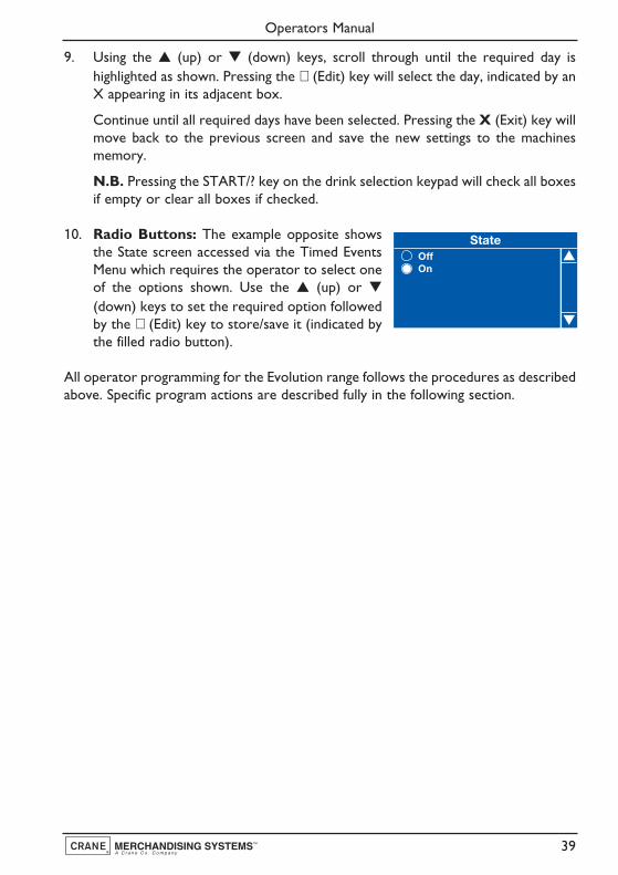
9. Using the ▲ (up) or ▼ (down) keys, scroll through until the required day ishighlighted as shown. Pressing the ↵ (Edit) key will select the day, indicated by anX appearing in its adjacent box.
Continue until all required days have been selected. Pressing the X (Exit) key willmove back to the previous screen and save the new settings to the machinesmemory.
N.B. Pressing the START/? key on the drink selection keypad will check all boxesif empty or clear all boxes if checked.
10. Radio Buttons: The example opposite showsthe State screen accessed via the Timed EventsMenu which requires the operator to select oneof the options shown. Use the ▲ (up) or ▼
(down) keys to set the required option followedby the ↵ (Edit) key to store/save it (indicated bythe filled radio button).
All operator programming for the Evolution range follows the procedures as describedabove. Specific program actions are described fully in the following section.
Operators Manual
39

Section 7 - Operators Program
To access the Operators Program, enter theprogramming mode as described in section 6. Once inthe Operators Program the LCD on the front of themachine will display the top level programming menuscreen - Main Menu.
N.B. Coins In/Out will only be displayed on machinesfitted with an MDB coin mech.
Using the ▲ (up) or ▼ (down) keys, ↵ (Edit) key and X (Exit) key on the drinkselection keypad the operator can navigate quickly and easily through the operatorsprogram menus as described in Section 6.
7.1 Data Recall Menu
Entry into this menu allows the operator to viewNon-Resettable and Resettable Sales Data, view datarelating to Timed Events and Identification Numbersof installed components and (if feature enabled) viewSureVend™ assisted vend information. The Re-settable Sales Data and SureVend™ data menuscontain an extra sub-menu which allows the operator to delete the current data fromthe machines memory.
1. Non Resettable Sales Data: This menu allows the operator to view and recordmonetary and sales values. This data cannot be reset and will remain intact for theservice life of the controller board (unless the back-up battery is removed).
1. From the Data Recall screen highlight NonResettable Sales Data and press the ↵ (Edit) key.The LCD will display the screen as shownopposite. From this menu the operator can viewdata for the Overall Totals (highlighted), ByProduct, along with data relating to Cash,Cashless and Token Vends.
2. To view the Overall Totals screen, press the ↵ (Edit) key on the drink selectionkeypad. This menu displays both the total £ amount and total vend counts for thefollowing data:
Sales-£ Displays the total machine sales in £Sales-# Displays the total number of machine vends. This value
includes normal, discount and surcharge vend totals.
Operators Manual
40
Main Menu
Press EDIT to Select
Data RecallDiagnosticsPriceProduct ConfigurationCoins In/Out
System SettingsSecurity CodesTimed Events
Data RecallNon Resettable Sales DataResettable Sales DataTimed EventsIdentification NumbersSureVend
Press EDIT to Select
Non Resettable Sales DataOverall TotalsBy ProductCashCashlessToken
Press EDIT to Select

Discount-£ Displays the total monetary value of all discounts in £Discount-# Displays the total number of discounted vends
Test Vend-£ Displays the total monetary value of all test vends in £Test Vend-# Displays the total number of test vendsSurcharge-£ Displays the total monetary value of all surcharges in £Surcharge-# Displays the total number of surcharge vendsFree Vend-£ Displays the total monetary value of all free vends in £Free Vend-# Displays the total number of free vends
N.B. All sales data is presented in a format required by the latest European VendingAssociation Data Transfer Standards (EVA DTS). Surcharge data fields are notsupported by Evolution machines.
3. Scroll through the list displayed using the ▲ (up)or ▼ (down) keys on the front panel and recordthe audit data.
When complete, press the X (Exit) key on thedrink selection keypad to return to the NonResettable Sales Data menu screen.
4. The operator can also view and record audit data by individual product. Press the▼ (down) key on the drink selection keypad to highlight By Product on the NonResettable Sales Data menu screen.
5. Press the ↵ (Edit) key on the keypad to enter the By Product menu screen. Thismenu contains all of the drink selections available from the machine. Use the ▲(up) or ▼ (down) keys on the drink selection keypad to scroll through the menuuntil the required selection is highlighted.
6. Press the ↵ (Edit) key on the keypad to enter thehighlighted selection e.g. chocolate. The LCD willdisplay the screen as shown opposite. This menudisplays both the total £ amount and total vendcount as previously described.
N.B. Individual By Product screens also displaythe price set for the selection as shown.
The operator can then scroll through the list displayed using the ▲ (up) or ▼(down) keys on the drink selection keypad and record the audit data.
Operators Manual
41

Operators Manual
42
7. When complete, press the X (Exit) key on the drink selection keypad to returnthe machine to the previous screen. The operator can then view data for moreselections using the procedure described above and also access further menus viathe Non Resettable Sales Data menu relating to Cash, Cashless and Token auditdata.
8. To return the machine to standby mode, press the X (Exit) key repeatedly untilthe LCD displays the standby screen.
2. Resettable Sales Data: This menu contains similar data to that available from theNon Resettable Sales Data menu. However, once viewed and recorded, data from thismenu can be cleared from the machines memory.
1. From the Data Recall screen, highlight ResettableSales Data and press the ↵ (Edit) key. The LCDwill display the screen as shown opposite andallow the operator to view data for allparameters as described for Non-ResettableSales Data. Additionally the menu allows theoperator to delete all resettable data via theClear Data menu.
2. To view the Overall Totals screen, press the ↵(Edit) key on the drink selection keypad. Thismenu displays both the total £ amount and totalvend count (since the last time it was cleared) forthe data fields shown.
N.B. Please see page 40 & 41 for detaileddescriptions of these data fields.
3. Scroll through the list displayed using the ▲ (up) and ▼ (down) keys on the frontpanel and record the audit data. When complete, press the X (Exit) key on thedrink selection keypad to return to the Resettable Sales Data menu screen.
4. The operator can also view and record resettable monetary and vend data forindividual product by entering the By Product menu, and also view and recorddata relating to Cash, Cashless and Token vends using their relevant sub-menus.
Resettable Sales DataOverall TotalsBy ProductCashCashlessToken
Clear DataPress EDIT to Select
Overall Totals

Once the operator has viewed and recorded required information from these sub-menu’s, the data can be deleted via the Clear Data sub menu.
5. From the Resettable Sales Data screen, highlightthe Clear Data sub menu using the ▼ (down) keyand press the ↵ (Edit) key. The LCD on the frontof the machine will display the screen as shownopposite, warning the operator that all data willbe deleted.
Either press the ↵ (Edit) key to clear the data or press the X (Exit) key to exitthe menu without clearing the data.
3. Timed Events
1. From the Data Recall menu scroll down andhighlight Timed Events then press the ↵ (Edit)key. The LCD will display the screen as shownopposite. From this menu screen the operatorcan access then view and record informationrelating to the four events as shown.
2. To view the Power Losses screen, press the ↵(Edit) key. The screen displays a list of the 10most recent occasions when power to themachine has been disconnected in date, time ofday and period format. Press the X (Exit) key toreturn to the Timed Events menu.
3. Press the ▼ (down) key to highlight Last Data Clear, Last Vend and Last ClockSet. Information for these events is displayed along the bottom of the screen.
4. Identification Numbers
1. From the Data Recall menu scroll down andhighlight Identification Numbers then press the ↵(Edit) key. The LCD will display the screen asshown opposite. From this menu the operatorcan access and then view serial number, partnumber and version type information relating tothe main PCB and any MDB coin/card mechanism fitted to the machine.
N.B. Coin Mechanism, Bill Validator and Card Reader will only be displayed if anMDB device is fitted to the machine.
Operators Manual
43
Clear Data
Are you sure you wantto set all resettabledata to zero?
CANCEL - EXIT OK - EDIT
Timed EventsPower LossesLast Data ClearLast VendLast Clock Set
Power Losses05-08-05 12:25 10Min04-08-05 12:10 12Min
Identification NumbersMain PCBCoin MechanismBill ValidatorCard Reader
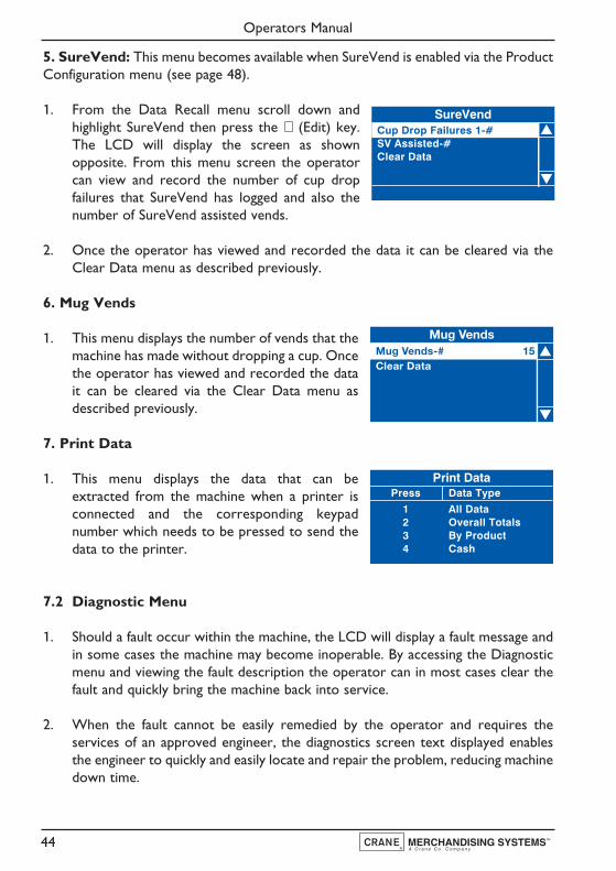
5. SureVend: This menu becomes available when SureVend is enabled via the ProductConfiguration menu (see page 48).
1. From the Data Recall menu scroll down andhighlight SureVend then press the ↵ (Edit) key.The LCD will display the screen as shownopposite. From this menu screen the operatorcan view and record the number of cup dropfailures that SureVend has logged and also thenumber of SureVend assisted vends.
2. Once the operator has viewed and recorded the data it can be cleared via theClear Data menu as described previously.
6. Mug Vends
1. This menu displays the number of vends that themachine has made without dropping a cup. Oncethe operator has viewed and recorded the datait can be cleared via the Clear Data menu asdescribed previously.
7. Print Data
1. This menu displays the data that can beextracted from the machine when a printer isconnected and the corresponding keypadnumber which needs to be pressed to send thedata to the printer.
7.2 Diagnostic Menu
1. Should a fault occur within the machine, the LCD will display a fault message andin some cases the machine may become inoperable. By accessing the Diagnosticmenu and viewing the fault description the operator can in most cases clear thefault and quickly bring the machine back into service.
2. When the fault cannot be easily remedied by the operator and requires theservices of an approved engineer, the diagnostics screen text displayed enablesthe engineer to quickly and easily locate and repair the problem, reducing machinedown time.
Operators Manual
44
SureVendCup Drop Failures 1-# SV Assisted-# Clear Data
Print Data Press Data Type
1 All Data 2 Overall Totals 3 By Product 4 Cash

7.3 Price Menu
Entry into this menu allows the operator to enter individual prices for each drinkselection available, one price for all drink selections and set a discount to be appliedfor customers who use their own cup/mug. The menu also contains a sub menu whichallows the operator to view the highest and lowest price set in the machines memory.
N.B. Values entered via this menu are only applicable to machines fitted with acoin/card system.
1. Individual Prices: This sub menu allows theoperator to set an individual price for each drinkselection available from the machine.
1. With Individual Prices highlighted as shownopposite, press the ↵ (Edit) key to access themenu.
2. Upon entry into this sub menu, all drinkselections available from the machine are listedalong with the current drink price for thehighlighted selection. The example shownillustrates an Instant Coffee selection with a priceset currently at 35p.
3. To change the price of the highlighted selection,press the ↵ (Edit) key. The LCD will change anddisplay the screen as shown. To update the price,e.g. increase to 45p, press the sequence 0-0-0-4-5 using the appropriate number keys on thedrink selection keypad.
4. Press the ↵ (Edit) key to return to the Individual Prices screen and verify that thenew price displays in the status line along the bottom of the display. Use the ▲(up) or ▼ (down) keys to highlight further selections.
2. Entire Machine: This sub menu allows the operator to set a single price for allselections available from the machine.
1. When highlighted from within the Price menu,the LCD will display the screen, with the currentvalue (e.g. 40p), as shown.
Operators Manual
45
Individual Prices
=£ 0.35
Instant CoffeeInstant Decaff CoffeeInstant TeaChocolateCappuccino
Instant Coffee
0-9 to Edit ValueEdit when Finished
000.45
Price
=£ 0.40
Individual PricesEntire MachineMug DiscountView High/Low Price
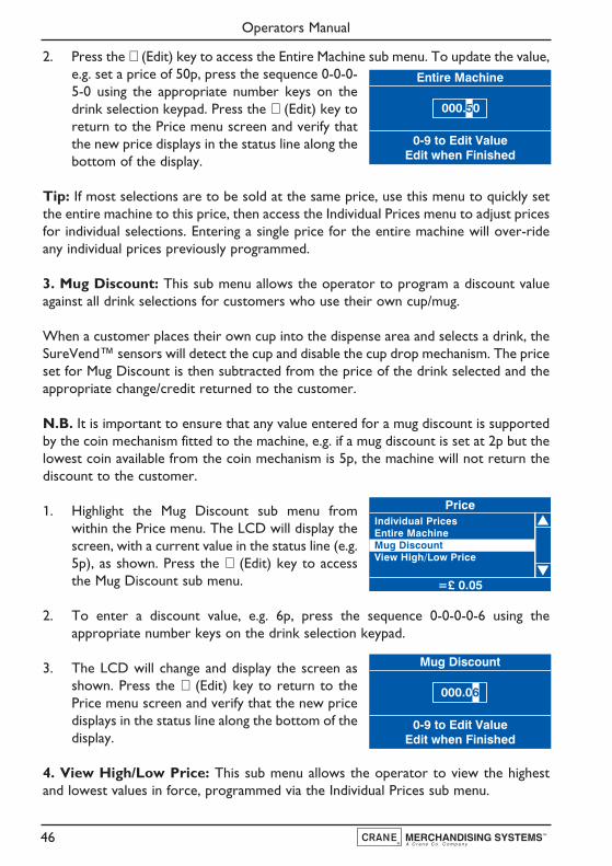
2. Press the ↵ (Edit) key to access the Entire Machine sub menu. To update the value,e.g. set a price of 50p, press the sequence 0-0-0-5-0 using the appropriate number keys on thedrink selection keypad. Press the ↵ (Edit) key toreturn to the Price menu screen and verify thatthe new price displays in the status line along thebottom of the display.
Tip: If most selections are to be sold at the same price, use this menu to quickly setthe entire machine to this price, then access the Individual Prices menu to adjust pricesfor individual selections. Entering a single price for the entire machine will over-rideany individual prices previously programmed.
3. Mug Discount: This sub menu allows the operator to program a discount valueagainst all drink selections for customers who use their own cup/mug.
When a customer places their own cup into the dispense area and selects a drink, theSureVend™ sensors will detect the cup and disable the cup drop mechanism. The priceset for Mug Discount is then subtracted from the price of the drink selected and theappropriate change/credit returned to the customer.
N.B. It is important to ensure that any value entered for a mug discount is supportedby the coin mechanism fitted to the machine, e.g. if a mug discount is set at 2p but thelowest coin available from the coin mechanism is 5p, the machine will not return thediscount to the customer.
1. Highlight the Mug Discount sub menu fromwithin the Price menu. The LCD will display thescreen, with a current value in the status line (e.g.5p), as shown. Press the ↵ (Edit) key to accessthe Mug Discount sub menu.
2. To enter a discount value, e.g. 6p, press the sequence 0-0-0-0-6 using theappropriate number keys on the drink selection keypad.
3. The LCD will change and display the screen asshown. Press the ↵ (Edit) key to return to thePrice menu screen and verify that the new pricedisplays in the status line along the bottom of thedisplay.
4. View High/Low Price: This sub menu allows the operator to view the highestand lowest values in force, programmed via the Individual Prices sub menu.
Operators Manual
46
Entire Machine
0-9 to Edit ValueEdit when Finished
000.50
Price
=£ 0.05
Individual PricesEntire MachineMug DiscountView High/Low Price
Mug Discount
0-9 to Edit ValueEdit when Finished
000.06
N.B. If a single price is currently in force, this value will be displayed in both fields.
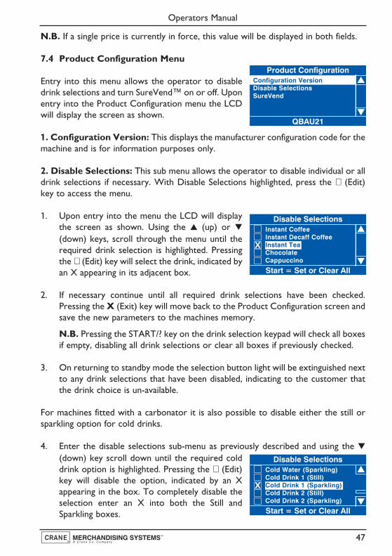
7.4 Product Configuration Menu
Entry into this menu allows the operator to disabledrink selections and turn SureVend™ on or off. Uponentry into the Product Configuration menu the LCDwill display the screen as shown.
1. Configuration Version: This displays the manufacturer configuration code for themachine and is for information purposes only.
2. Disable Selections: This sub menu allows the operator to disable individual or alldrink selections if necessary. With Disable Selections highlighted, press the ↵ (Edit)key to access the menu.
1. Upon entry into the menu the LCD will displaythe screen as shown. Using the ▲ (up) or ▼
(down) keys, scroll through the menu until therequired drink selection is highlighted. Pressingthe ↵ (Edit) key will select the drink, indicated byan X appearing in its adjacent box.
2. If necessary continue until all required drink selections have been checked.Pressing the X (Exit) key will move back to the Product Configuration screen andsave the new parameters to the machines memory.
N.B. Pressing the START/? key on the drink selection keypad will check all boxesif empty, disabling all drink selections or clear all boxes if previously checked.
3. On returning to standby mode the selection button light will be extinguished nextto any drink selections that have been disabled, indicating to the customer thatthe drink choice is un-available.
For machines fitted with a carbonator it is also possible to disable either the still orsparkling option for cold drinks.
4. Enter the disable selections sub-menu as previously described and using the ▼(down) key scroll down until the required colddrink option is highlighted. Pressing the ↵ (Edit)key will disable the option, indicated by an Xappearing in the box. To completely disable theselection enter an X into both the Still andSparkling boxes.
Operators Manual
47
Product Configuration
QBAU21
Configuration VersionDisable SelectionsSureVend
Disable Selections
Start = Set or Clear All
Instant CoffeeInstant Decaff CoffeeInstant TeaChocolateCappuccino
X
Disable Selections
Start = Set or Clear All
Cold Water (Sparkling)Cold Drink 1 (Still)Cold Drink 1 (Sparkling)Cold Drink 2 (Still)Cold Drink 2 (Sparkling)
X
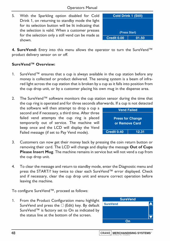
5. With the Sparkling option disabled for ColdDrink 1, on returning to standby mode the lightfor its selection button will be lit indicating thatthe selection is valid. When a customer pressesfor the selection only a still vend can be made asshown.
4. SureVend: Entry into this menu allows the operator to turn the SureVend™product delivery sensor on or off.
SureVend™ Overview:
1. SureVend™ ensures that a cup is always available in the cup station before anymoney is collected or product delivered. The sensing system is a beam of infra-red light across the cup station that is broken by a cup as it falls into position fromthe cup drop unit, or by a customer placing his own mug in the dispense area.
2. The SureVend™ software monitors the cup station sensor during the time thatthe cup ring is operated and for three seconds afterwards. If a cup is not detectedthe software will then attempt to drop a cup asecond and if necessary, a third time. After threefailed vend attempts the cup ring is placedtemporarily out of service. The machine willbeep once and the LCD will display the VendFailed message (if set to Pay Vend mode).
3. Customers can now get their money back by pressing the coin return button orremoving their card. The LCD will change and display the message Out of CupsPlease Insert Mug. The machine remains in service but will not vend a cup fromthe cup drop unit.
4. To clear the message and return to standby mode, enter the Diagnostic menu andpress the START/? key twice to clear each SureVend™ error displayed. Checkand if necessary, clear the cup drop unit and ensure correct operation beforeleaving the machine.
To configure SureVend™, proceed as follows:
1. From the Product Configuration menu highlightSureVend and press the ↵ (Edit) key. By defaultSureVend™ is factory set to On as indicated bythe status line at the bottom of the screen.
Operators Manual
48
Cold Drink 1 (Still)
(Press Start)
01.50Credit 0.00
Vend Failed
Press for Changeor Remove Card
12.31Credit 0.40
SureVendSureVend
On

2. To disable SureVend™, press the ↵ (Edit) key toenter the SureVend On/Off screen. Use the ▲
(up) key to select Off (indicated by the filledradio button).
3. Press the ↵ (Edit) key to confirm the selection and return to the SureVend screen.Verify that the status line at the bottom of the screen displays Off when SureVendis highlighted.
4. Pressing the X (Exit) key will move back to the Product Configuration screen andsave the new parameter to the machines memory.
7.5 Coins In/Out Menu
N.B. Coins In/Out will only be displayed on machines fitted with an MDB coin mech.
The Coins In/Out menu emulates the coin mechanism from the front end screen andallows the operator to view information relating to the coin mechanism and eject coinsfrom the machine without opening the door.
1. From the Main Menu screen use the ▼ (down)key to scroll through the menu until CoinsIn/Out is highlighted. Press the ↵ (Edit) key toaccess the menu screen which will look similar tothe example shown.
2. From this screen the operator can view the coin sets in the coin mechanism, thenumber of coins in each coin stack and the total value of the coins. To eject coinsfrom the mechanism the operator simply presses the relevant button on thekeypad eg pressing button 4 will eject a 50p coin. The count will reduce to 7 andthe value to 3.50.
7.6 System Settings Menu
This menu allows the operator to view informationrelevant to the machine and its location, set thecurrent time and date, set and view DTS information,backup and restore machine software, view themachine and I/O board software versions installed inthe machine and set temperature and idle screendisplay options.
N.B. Custom Messages is not supported at this time.
Operators Manual
49
Coins In/OutPress
1234
Coin0.050.100.200.50
Count341898
Value1.701.801.804.00
System Settings
Press EDIT to Select
Machine InformationClockDTSBackup/RestoreSoftware Version
I/O Board SoftwareTemperature UnitsIdle Screen OptionsCustom Messages

1. Machine Information: This sub-menu allows the operator to view theidentification for the machine and its location.
1. From the Systems Settings menu highlightMachine Information and press the ↵ (Edit) key.The LCD will display the screen as shownopposite. To view the Machine ID press the ↵(Edit) key.
2. When complete, press the X (Exit) key to return to the Machine Informationmenu screen. If necessary press the ▼ (down) then ↵ (Edit) keys to highlight thenenter the Machine Location screen. When complete press the X (Exit) key.
2. Clock: The machine displays the current time in either 12 or 24 hour format.
Upon entry to the System Settings menu, the Clock sub menu is highlighted. Press the↵ (Edit) key to access the Clock sub menu screen. This menu allows the operator toset the date, time and daylight saving via 3 separate sub menus.
N.B. The current date, time and daylight saving (when highlighted) held in the machinesmemory are displayed in the status line at the bottom of the screen.
1. Date: Press the ↵ (Edit) key to enter the Datemenu. The date is displayed in day, month, yearformat. To set the date, e.g. 27th January 2006,press the sequence 2-7-0-1-0-6 using theappropriate number keys on the drink selectionkeypad.
N.B. The text ‘Press 0-9 to Edit Value’ displayed in the status line at thebottom of the screen will alternate with the text ‘Press Start To ChangeMode’. Pressing the START/? key on the drink selection keypad allows the dateto be displayed in month, day, year format.
Pressing the ↵ (Edit) key will move back to the Clock menu screen and save thedate to the machines memory. Confirm that the status line at the bottom of thescreen displays the correct date when Date is highlighted.
2. Time: From the Clock menu screen press the ▼ (down) key to highlight the Timemenu followed by the ↵ (Edit) key. The LCD willdisplay the screen as shown opposite. By defaultthe time is displayed in 12 hour format. To entera time of 10:30 PM press the sequence 1-0-3-0on the drink selection keypad.
Operators Manual
50
Machine Information
Press EDIT to Select
Machine IDMachine Location
Date
Press 0-9 to Edit Value
dd - mm - yy
00 0000
Time
Press 0-9 to Edit Value
hh / mm / mode: 12 / 24
00 AM00 :

As the operator presses the final zero, the AMvalue will appear within a dotted box and thetext at the bottom of the LCD will now read‘Press Arrows To Select’. Press the ▲ (up) or▼ (down) key until PM appears in the box.
Pressing the ↵ (Edit) key will move back to the Clock menu screen and save thenew time to the machines memory. Confirm that the status line at the bottom ofthe screen displays the correct time when Time is highlighted.
N.B. When set to 12 hour format, the program will only allow the operator toset the numbers 0 or 1 in the first field. Once the number 24 has been enteredvia the ▲ (up) or ▼ (down) keys to indicate 24 hour format, the operator canreset the first two values to reflect 10:30 PM in 24 hour format e.g. 22:30.
3. Daylight Saving: From the Clock menu screenpress the ▼ (down) key to highlight the DaylightSaving menu followed by the ↵ (Edit) key. TheLCD will display the screen as shown opposite.
By default daylight savings time is set to Off. Tochoose one of the available options, press the ▲(up) or ▼ (down) key until selected (indicated by the filled radio button) followedby the ↵ (Edit) key. Ensure that the required setting is displayed in the status lineat the bottom of the screen. Press the X (Exit) key to return to the main menu.
3. DTS: Entry into this menu allows the operator to configure the machine in orderto send audit data relating to sales and events stored in the machines memory to adata carrier or other device.
Data Transfer Standard (EVA-DTS) - Overview: The standard makes it possibleto transfer information from vending machines/payment systems to PC-basedaccounting/management systems and/or the opposite way. It is important that allsuppliers of vending machines and payment systems agree to a common standard forthe Electronic Data Transfer, because only this way the operator can be sure that allhis equipment can be read out and programmed by means of the same handheldterminal.
1. DTS Standby Mode: Scroll down and highlightDTS from the System Settings menu. Press the ↵(Edit) key to access the menu. The LCD willdisplay the screen as shown. The first sub-menuDTS Standby Mode is highlighted with its currentstate (DDCMP) shown in the bottom line.
Operators Manual
51
Daylight Savings TimeNorth AmericanUS 2007EuropeanAustralianOff
Time
Press Arrows To Select
hh / mm / mode: 12 / 24
PM10 : 30
DTS
DDCMP
DTS Standby ModeDTS Audit ListCA304 Data TypeData Reset ModeEvent Reset Mode
Printer Baud Rate
The machine is factory set to enable data transfer via the optical DDCMP link. Tochange this to the DEX setting, press the ↵ (Edit) key to access the menu and the▲ (up) key to select DEX (indicated by the filled radio button. Press the ↵ (Edit)key to save the selection.
N.B. Even if the default is set to DDCMP, once the controller detects a DEXactivity, it will automatically switch to the other mode. However, setting thedefault to the correct protocol will speed up response time.
The operator can now download data from the machine by plugging a DEXenabled device into the DEX port (J36) on the I/O board, located on the rear ofthe door.
2. DTS Audit List: From this sub-menu theoperator can select which data is transferredfrom the machine to a DEX/DDCMP datacarrier. Scroll down and highlight DTS AuditData. Press the ↵ (Edit) key to access the menu.The LCD will display the screen as shown.
All data and events fields within a vending machine are assigned a unique codedetermined by the Standard. From this sub-menu the operator can choose toallow all fields to be available for download by pressing the START/? key orscrolling through the list and adding an X to the required fields.
3. CA304 Data Type: This sub-menu determines whether the the data will bedisplayed as currency or numerical, for example, assuming that the value of poundcoins in the machine is £3.00, when set to currency CA304 will read 300 in theDEX/DDCMP report. When set to numeric it will read 3.
4. Data Reset Mode: This field can be set to either AUTO or SAVE from withinthe sub-menu. When set to AUTO, all resettable data will be reset after asuccessful read.
5. Event Reset Mode: This field can be set to either AUTO or SAVE from withinthe sub-menu. When set to AUTO, all event data will be reset after a successfulread.
6. Printer Baud Rate: This allows the operator to set the correct baud rate fora serial printer if one is to be used. It is important for this to be set correctly toensure successful data transfer.
4. Backup/Restore: This menu allows the operator to manually backup informationstored in the machines memory to the controller board.
Operators Manual
52
DTS Audit List
Start (?)=Set or Clear All
ID 1ID 2ID 3ID 4ID 5
XXXXX

N.B. It is also possible for the operator to programme Backup as a timed event, thusensuring even greater security for the information stored in memory. This ensures thatthe machine can easily be restored to its last operational state should the informationbe lost through corruption or power failure. For full details see page 60.
1. Scroll down and highlight Backup/Restore fromthe System Settings menu. Press the ↵ (Edit) keyto access the menu. If this is the first time that abackup has been selected the LCD will displaythe screen as shown.
2. Press the ↵ (Edit) key to access the menu. TheLCD will display the screen as shown. To backupthe memory press the ↵ (Edit) key. After a fewseconds the machine will beep once and theInitialising screen will be displayed before themachine returns to standby mode, ready to vend.
3. When accessing the Backup/Restore sub-menuafter backups of the memory have been made,the information changes and the operator ispresented with the screen as shown. The firstsub-menu, Last Backup is highlighted with thedate and time this occurred displayed at thebottom of the screen.
4. To restore the machines memory to the lastavailable backup, scroll down using the ▼ (down)key, highlight Restore Data and press the ↵ (Edit)key to access the menu. The LCD will display thescreen as shown. Press the ↵ (Edit) key torestore the backed up data. After a few secondsthe machine will beep once and the Initialising screen will be displayed before themachine returns to standby mode, ready to vend.
5. Software Version: The Software version menu displays the version number of thesoftware installed and is for information only. The menu also displays the current timeand date.
6. I/O Board Software: This menu displays the version number of the I/O boardsoftware installed and is for information only.
Operators Manual
53
Backup/Restore
Press EDIT to Select
Backup Data
Backup Data
Are you sure you wantto backup allNVM data?
CANCEL - EXIT OK - EDIT
Backup/Restore
23-09-05 11:17
Last BackupBackup DataRestore Data
Restore Data
Are you sure you wantto restore the datafrom the backup?
CANCEL - EXIT OK - EDIT

7. Temperature Units: This menu allows theoperator to change the way that the temperature isdisplayed, either °C or °F, on the LCD when themachine is in standby mode. Use the ▲ (up) or ▼
(down) keys to set the required option followed bythe ↵ (Edit) key to store/save it (indicated by the filledradio button).
8. Idle Screen Options: This menu allows the operator to configure the LCD sothat it displays either the time or the time and water temperature with the standbymessage when idle. To configure the idle screen options, proceed as follows:
1. From the System Settings menu press the ▼ (down) key to highlight Idle ScreenOptions and press the ↵ (Edit) key to access the menu.
2. Press the ▼ (down) key to highlight the required option, eg Time and Temp(indicated by the filled radio button). The LCDwill display the screen as shown opposite. Pressthe ↵ (Edit) key to return to the System Settingsscreen. With Idle Screen Options highlighted,verify that the status line confirms the option isset to Time and Temp.
3. Press the X (Exit) key until the machine exits theengineers program into standby mode. The LCDwill display the standby message with the timeand date as shown.
7.7 Security Codes Menu
The security code for entry into the Operators Program is factory set so that theoperator presses button 1 on the service keypad followed by the sequence 2-2-2-2 onthe drink selection keypad. On no account should this code be altered without firstconsulting your supervisor or manager.
7.8 Timed Events Menu
1. Time of Day Events: From this menu the operator can set up inhibited vendperiods, free vend periods and discounted vend periods.
The following example describes how the operator can program the machine to freevend specific drink selections between 10.30 am and 2:30 pm on week days.
Operators Manual
54
Please Makea Selection
Time: 10:45 Temp: 90C
Temperature UnitsCelsius ( °C)Fahrenheit ( °F)
Idle Screen OptionsTimeTime and TempNone

1. From the Main Menu press the ▼ (down) keyuntil Timed Events is highlighted then press the↵ (Edit) key twice to access the Time of Daymenu screen. The LCD will display the screen asshown.
N.B. Although event 1 is shown as Inhibit, it is possible for the operator to setevent 1 as the first Free Vend (or Discounted Vend) period.
2. Press the ↵ (Edit) key to access the menu. TheLCD will display the screen as shown. By defaultthe current State is set to Off as indicated by thestatus line at the bottom of the screen.
3. Press the ↵ (Edit) key to access the State submenu. Using the ▼ (down) key, set the state toOn (indicated by the filled radio button). Pressthe ↵ (Edit) key to return to the Event 1 screen.Verify that the status line confirms the State is setto On.
4. Press the ▼ (down) key to highlight Event Type and press the ↵ (Edit) key toaccess the menu. Using the ▼ (down) key, setthe Event Type to Free Vend (indicated by thefilled radio button). Press the ↵ (Edit) key toreturn to the Event 1 screen. Verify that thestatus line confirms the Event Type is set to FreeVend.
5. Press the ▼ (down) key to highlight Start Time and press the ↵ (Edit) key. Fromthis menu the operator sets the time at whichthe free vend period will start. Press thesequence 1-0-3-0, using the drink selectionkeypad, to set the time. If necessary use the ▲(up) or ▼ (down) key until AM appears in thedotted box.
6. Press the ↵ (Edit) key to return to the Event 1 screen. Verify that the correctstart time is displayed in the status line at the bottom of the screen.
Operators Manual
55
Time Of Day Events1 Inhibit Off2 Inhibit Off3 Inhibit Off4 Inhibit Off5 Free Vend Off6 Free Vend Off
Event TypeInhibitFree VendDiscount
Start Time
Press Arrows To Select
hh / mm / mode: 12 / 24
AM10 : 30
1
Off
StateEvent TypeStart TimeStop TimeDays Of Week
StateOffOn
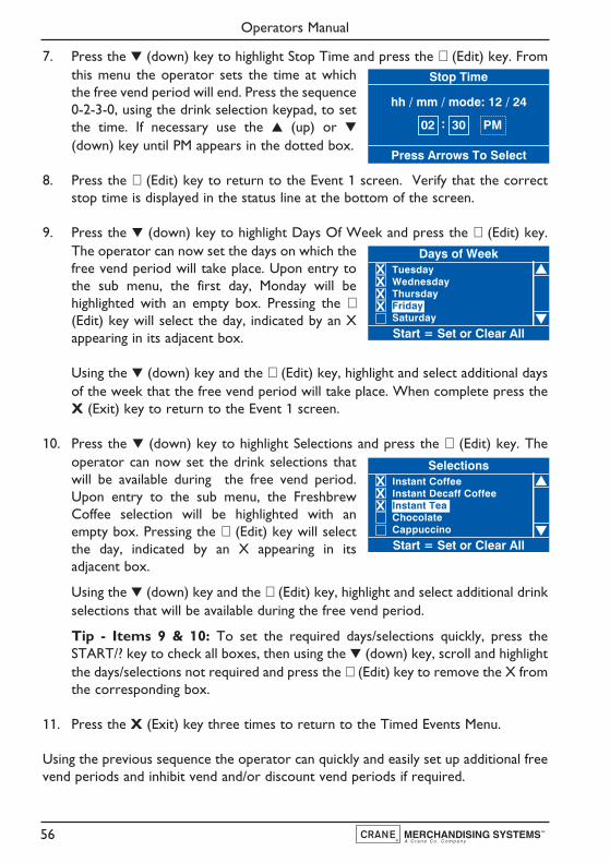
7. Press the ▼ (down) key to highlight Stop Time and press the ↵ (Edit) key. Fromthis menu the operator sets the time at whichthe free vend period will end. Press the sequence0-2-3-0, using the drink selection keypad, to setthe time. If necessary use the ▲ (up) or ▼
(down) key until PM appears in the dotted box.
8. Press the ↵ (Edit) key to return to the Event 1 screen. Verify that the correctstop time is displayed in the status line at the bottom of the screen.
9. Press the ▼ (down) key to highlight Days Of Week and press the ↵ (Edit) key.The operator can now set the days on which thefree vend period will take place. Upon entry tothe sub menu, the first day, Monday will behighlighted with an empty box. Pressing the ↵(Edit) key will select the day, indicated by an Xappearing in its adjacent box.
Using the ▼ (down) key and the ↵ (Edit) key, highlight and select additional daysof the week that the free vend period will take place. When complete press theX (Exit) key to return to the Event 1 screen.
10. Press the ▼ (down) key to highlight Selections and press the ↵ (Edit) key. Theoperator can now set the drink selections thatwill be available during the free vend period.Upon entry to the sub menu, the FreshbrewCoffee selection will be highlighted with anempty box. Pressing the ↵ (Edit) key will selectthe day, indicated by an X appearing in itsadjacent box.
Using the ▼ (down) key and the ↵ (Edit) key, highlight and select additional drinkselections that will be available during the free vend period.
Tip - Items 9 & 10: To set the required days/selections quickly, press theSTART/? key to check all boxes, then using the ▼ (down) key, scroll and highlightthe days/selections not required and press the ↵ (Edit) key to remove the X fromthe corresponding box.
11. Press the X (Exit) key three times to return to the Timed Events Menu.
Using the previous sequence the operator can quickly and easily set up additional freevend periods and inhibit vend and/or discount vend periods if required.
Operators Manual
56
Days of Week
Start = Set or Clear All
TuesdayWednesdayThursdayFridaySaturday
XX
XX
Selections
Start = Set or Clear All
Instant CoffeeInstant Decaff CoffeeInstant TeaChocolateCappuccino
XXX
Stop Time
Press Arrows To Select
hh / mm / mode: 12 / 24
PM02 : 30

12. When setting up a discount price period it is necessary for the operator to entera value for the discount. Follow the procedure as described previously to entera discount vend period and set the state, start time, stop time and days of theweek that the event will occur.
13. The operator can now enter a Discount menu inorder to enter a discount value as a percentage(%). The LCD will display a screen similar to theone shown opposite. With Discount highlighted,press the ▼ (Edit) key to access the Discountscreen.
14. To enter the discount value, e.g. 50%, press thesequence 5-0 using the appropriate number keyson the drink selection keypad. Press the ↵ (Edit)key to return to the 11 (Discount) screen andverify that the status line displays the discountpercentage value entered.
N.B. When machine is fitted with a coin mechanism, please ensure that discountvalue entered can be supported by the coin tubes.
15. Press the X (Exit) key three times to return to the Main Menu screen.
2. Sanitation Events Menu: This sub menu allows the operator to select periodswhen the machine will automatically flush through the water system via the 6 timedand 6 post vend flush periods available. The default setting for all flush periods is Off.
1. From the Main Menu press the ▼ (down) key until Timed Events is highlightedthen press the ↵ (Edit) key.
2. Once in the Timed Events menu press the ▼
(down) key to highlight Sanitation Events Menuthen press the ↵ (Edit) key. The LCD will displaythe screen as shown.
The following example describes how the operator can program a timed event to flushthe water system at 07.00 am, everyday.
1. To set up the first timed flush, press the ↵ (Edit)key to access the 1 Timed sub menu. The LCDwill change and display the screen as shown. Bydefault the current State is set to Off as indicatedby the status line at the bottom of the screen.
Operators Manual
57
11
0%
Event TypeStart TimeStop TimeDays Of WeekDiscount
Sanitation Events Menu1 Timed Off2 Timed Off3 Timed Off4 Timed Off5 Timed Off6 Timed Off
1
Off
StateEvent TypeStart TimeDays Of Week
Discount
0-9 to Edit ValueEdit when Finished
50
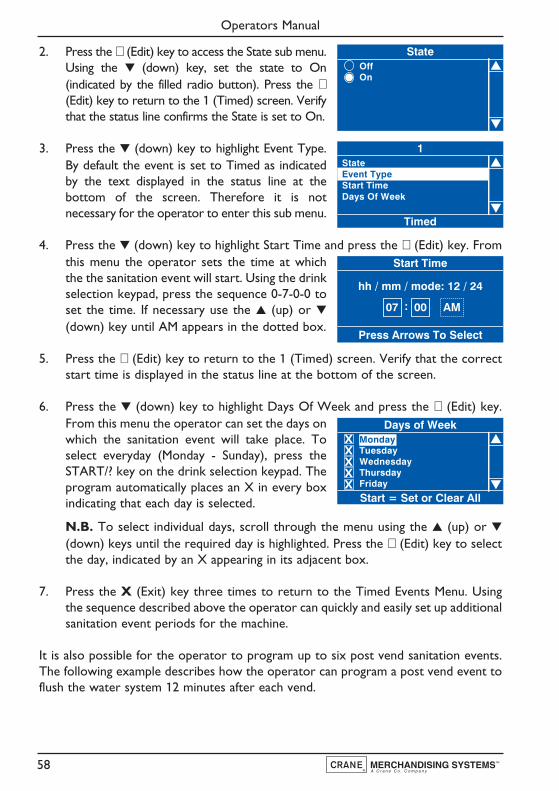
2. Press the ↵ (Edit) key to access the State sub menu.Using the ▼ (down) key, set the state to On(indicated by the filled radio button). Press the ↵(Edit) key to return to the 1 (Timed) screen. Verifythat the status line confirms the State is set to On.
3. Press the ▼ (down) key to highlight Event Type.By default the event is set to Timed as indicatedby the text displayed in the status line at thebottom of the screen. Therefore it is notnecessary for the operator to enter this sub menu.
4. Press the ▼ (down) key to highlight Start Time and press the ↵ (Edit) key. Fromthis menu the operator sets the time at whichthe the sanitation event will start. Using the drinkselection keypad, press the sequence 0-7-0-0 toset the time. If necessary use the ▲ (up) or ▼(down) key until AM appears in the dotted box.
5. Press the ↵ (Edit) key to return to the 1 (Timed) screen. Verify that the correctstart time is displayed in the status line at the bottom of the screen.
6. Press the ▼ (down) key to highlight Days Of Week and press the ↵ (Edit) key.From this menu the operator can set the days onwhich the sanitation event will take place. Toselect everyday (Monday - Sunday), press theSTART/? key on the drink selection keypad. Theprogram automatically places an X in every boxindicating that each day is selected.
N.B. To select individual days, scroll through the menu using the ▲ (up) or ▼(down) keys until the required day is highlighted. Press the ↵ (Edit) key to selectthe day, indicated by an X appearing in its adjacent box.
7. Press the X (Exit) key three times to return to the Timed Events Menu. Usingthe sequence described above the operator can quickly and easily set up additionalsanitation event periods for the machine.
It is also possible for the operator to program up to six post vend sanitation events.The following example describes how the operator can program a post vend event toflush the water system 12 minutes after each vend.
Operators Manual
58
Start Time
Press Arrows To Select
hh / mm / mode: 12 / 24
AM07 : 00
Days of Week
Start = Set or Clear All
MondayTuesdayWednesdayThursdayFriday
X
XX
XX
StateOffOn
1
Timed
StateEvent TypeStart TimeDays Of Week

1. From the Main Menu press the ▼ (down) key until Timed Events is highlightedthen press the ↵ (Edit) key. Once in the TimedEvents menu press the ▼ (down) key to highlightSanitation Events Menu then press the ↵ (Edit)key. Press the ▼ (down) key until the first PostVend event is highlighted. The LCD will displaythe screen as shown.
2. With Post Vend highlighted, press the ↵ (Edit)key to access the 7 Post Vend sub menu. TheLCD will change and display the screen as shown.By default the current State is set to Off asindicated by the status line at the bottom of thescreen.
3. Press the ↵ (Edit) key to access the State submenu. Using the ▼ (down) key, set the state toOn (indicated by the filled radio button). Pressthe ↵ (Edit) key to return to the 7 (Post Vend)screen. Verify that the status line confirms theState is set to On.
4. Press the ▼ (down) key to highlight Event Type.By default the event is set to Timed as indicatedby the text displayed in the status line at thebottom of the screen. Therefore it is notnecessary for the operator to enter this submenu.
5. Press the ▼ (down) key to highlight Delay. The status line indicates the factorydefault delay which is set to 0.1hrs (6 minutes).To change the value so that the machine will selfclean 12 minutes after a drink is vended press the↵ (Edit) key to access the Delay sub menu. TheLCD will display the screen as shown. Using thedrink selection keypad, press the sequence 0-0-2 to set the new delay.
Press the ↵ (Edit) key and verify that the status line confirms that Delay (whenhighlighted) is set to 0.2hrs.
6. Press the X (Exit) key three times to return to the Timed Events Menu. Usingthe sequence described above the operator can quickly and easily set up additionalpost vend sanitation event periods for the machine if required.
Operators Manual
59
7
Off
StateEvent TypeDelay
Sanitation Events Menu2 Timed Off3 Timed Off4 Timed Off5 Timed Off6 Timed Off7 Post Vend Off
7
Post Vend
StateEvent TypeDelay
Delay
0-9 to Edit ValueEdit when Finished
00.2
StateOffOn
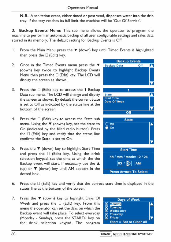
N.B. A sanitation event, either timed or post vend, dispenses water into the driptray. If the tray reaches its full limit the machine will be ‘Out Of Service’.
3. Backup Events Menu: This sub menu allows the operator to program themachine to perform an automatic backup of all user configurable settings and sales datastored in its memory. The default setting for Backup Events is Off.
1. From the Main Menu press the ▼ (down) key until Timed Events is highlightedthen press the ↵ (Edit) key.
2. Once in the Timed Events menu press the ▼
(down) key twice to highlight Backup EventsMenu then press the ↵ (Edit) key. The LCD willdisplay the screen as shown.
3. Press the ↵ (Edit) key to access the 1 BackupData sub menu. The LCD will change and displaythe screen as shown. By default the current Stateis set to Off as indicated by the status line at thebottom of the screen.
4. Press the ↵ (Edit) key to access the State submenu. Using the ▼ (down) key, set the state toOn (indicated by the filled radio button). Pressthe ↵ (Edit) key and verify that the status lineconfirms the State is set to On.
5. Press the ▼ (down) key to highlight Start Timeand press the ↵ (Edit) key. Using the drinkselection keypad, set the time at which the theBackup event will start. If necessary use the ▲
(up) or ▼ (down) key until AM appears in thedotted box.
6. Press the ↵ (Edit) key and verify that the correct start time is displayed in thestatus line at the bottom of the screen.
7. Press the ▼ (down) key to highlight Days OfWeek and press the ↵ (Edit) key. From thismenu the operator can set the days on which theBackup event will take place. To select everyday(Monday - Sunday), press the START/? key onthe drink selection keypad. The program
Operators Manual
60
Backup EventsBackup Data Off
1
Off
StateStart TimeDays Of Week
StateOffOn
Start Time
Press Arrows To Select
hh / mm / mode: 12 / 24
AM03 : 30
Days of Week
Start = Set or Clear All
MondayTuesdayWednesdayThursdayFriday
X
XX
XX
automatically places an X in every box indicating that each day is selected.
N.B. To select individual days, scroll through the menu using the ▲ (up) or ▼(down) keys until the required day is highlighted. Press the ↵ (Edit) key to selectthe day, indicated by an X appearing in its adjacent box.
Operators Manual
61

Section 8 - Dispense Pipe Lengths
8.1 Instant Machine - 6 Canister
Pipe No Diameter Length
1 6 mm I.D. x 10 mm O.D. 350 mm
2 6 mm I.D. x 10 mm O.D. 300 mm
3 6 mm I.D. x 10 mm O.D. 300 mm
4 6 mm I.D. x 10 mm O.D. 320 mm
5 6 mm I.D. x 10 mm O.D. 350 mm
H = Hot Water Dispense Pipe
Technical Manual
62
1 2 3 4 5
H
1
5
3
4
2
Hot Water

8.2 Instant Machine - 8 Canister
Pipe No Diameter Length
1 6 mm I.D. x 10 mm O.D. 350 mm
2 6 mm I.D. x 10 mm O.D. 300 mm
3 6 mm I.D. x 10 mm O.D. 300 mm
4 6 mm I.D. x 10 mm O.D. 320 mm
5 6 mm I.D. x 10 mm O.D. 360 mm
6 6 mm I.D. x 10 mm O.D. 410 mm
7 6 mm I.D. x 10 mm O.D. 460 mm
H = Hot Water Dispense Pipe
Technical Manual
63
1
2
3 4 5 6 7
H
1
5
6
7
3
4
2
Hot Water

8.3 Single Freshbrew Machine - Paperless Brewer
Pipe No Diameter Length
1 6 mm I.D. x 10 mm O.D. 350 mm
2 6 mm I.D. x 10 mm O.D. 300 mm
3 6 mm I.D. x 10 mm O.D. 300 mm
4 6 mm I.D. x 10 mm O.D. 300 mm
5 6 mm I.D. x 10 mm O.D. 330 mm
6 8 mm I.D. x 10 mm O.D. 370 mm
H = Hot Water Dispense Pipe
Operators Manual
64
1 2
34
5 6
H
1
5
6
3
4
2
Hot Water

8.4 Double Freshbrew Machine - Paperless Brewer
Pipe No Diameter Length
1 6 mm I.D. x 10 mm O.D. 350 mm
2 6 mm I.D. x 10 mm O.D. 300 mm
3 6 mm I.D. x 10 mm O.D. 300 mm
4 6 mm I.D. x 10 mm O.D. 300 mm
5 6 mm I.D. x 10 mm O.D. 330 mm
6 8 mm I.D. x 10 mm O.D. 390 mm
7 8 mm I.D. x 10 mm O.D. 370 mm
H = Hot Water Dispense Pipe
Operators Manual
65
1
2
3 4 5 6
7H
1
5
7
6
3
4
2
Hot Water
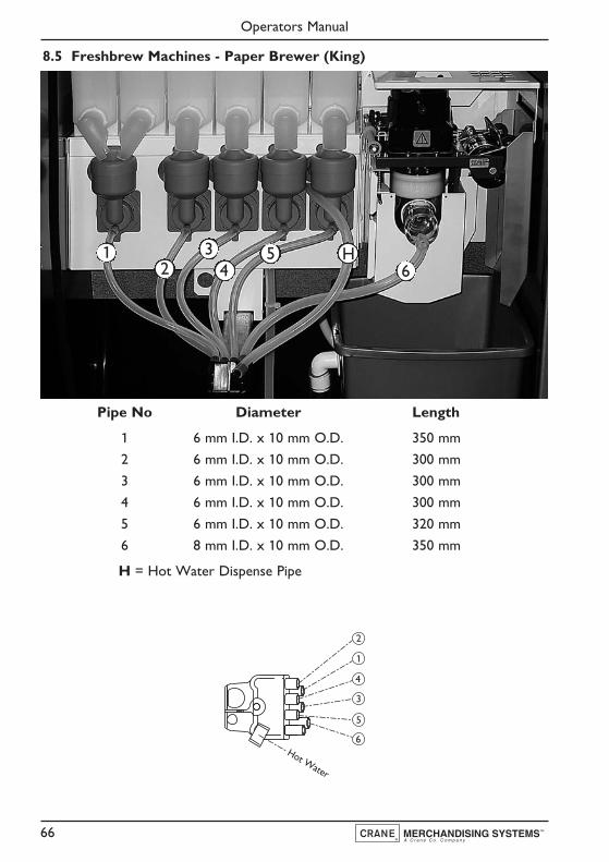
8.5 Freshbrew Machines - Paper Brewer (King)
Pipe No Diameter Length
1 6 mm I.D. x 10 mm O.D. 350 mm
2 6 mm I.D. x 10 mm O.D. 300 mm
3 6 mm I.D. x 10 mm O.D. 300 mm
4 6 mm I.D. x 10 mm O.D. 300 mm
5 6 mm I.D. x 10 mm O.D. 320 mm
6 8 mm I.D. x 10 mm O.D. 350 mm
H = Hot Water Dispense Pipe
Operators Manual
66
12
34
56
H
1
5
6
3
4
2
Hot Water
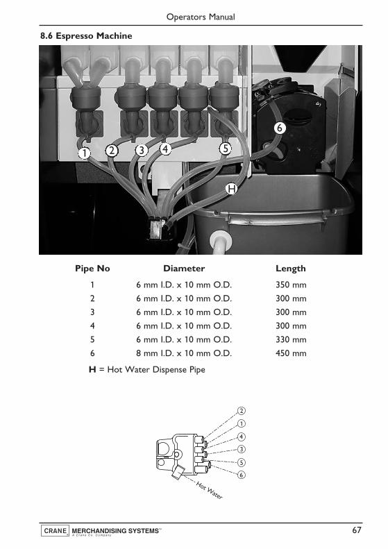
8.6 Espresso Machine
Pipe No Diameter Length
1 6 mm I.D. x 10 mm O.D. 350 mm
2 6 mm I.D. x 10 mm O.D. 300 mm
3 6 mm I.D. x 10 mm O.D. 300 mm
4 6 mm I.D. x 10 mm O.D. 300 mm
5 6 mm I.D. x 10 mm O.D. 330 mm
6 8 mm I.D. x 10 mm O.D. 450 mm
H = Hot Water Dispense Pipe
Operators Manual
67
1 2 3 4 5
6
H
1
5
6
3
4
2
Hot Water
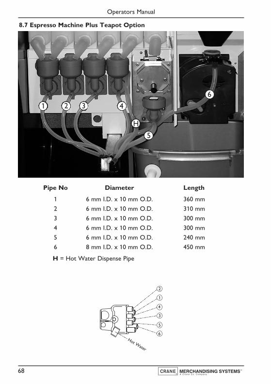
8.7 Espresso Machine Plus Teapot Option
Pipe No Diameter Length
1 6 mm I.D. x 10 mm O.D. 360 mm
2 6 mm I.D. x 10 mm O.D. 310 mm
3 6 mm I.D. x 10 mm O.D. 300 mm
4 6 mm I.D. x 10 mm O.D. 300 mm
5 6 mm I.D. x 10 mm O.D. 240 mm
6 8 mm I.D. x 10 mm O.D. 450 mm
H = Hot Water Dispense Pipe
Operators Manual
68
1 2 3 4
5
6
H
1
5
6
3
4
2
Hot Water

Section 9 - Error Messages And Simple Problem Solving
9.1 Error Messages
The table below lists the error messages that may be encountered and, whereapplicable, offers the operator solutions for curing them.
Safety First! Should the solution given not cure the problem, or the faultrequires the assistance of a trained service engineer, DO NOT ATTEMPT TOCURE THE FAULT YOURSELF. Contact your machine supplier for assistance.
Operators Manual
69
Error Message Cause Solution
Out Of Cups Cup stacks empty Refill cup stacks withPlease Insert Mug correct size and type
of cup
Sorry Out of Service Fault with mug sensor Switch off the powerMug Sensor Error and call engineer
Please Remove Cup A cup or mug has been Remove the cup or mug toleft in the vend area cancel the error
Sorry Out of Service Communications fault Switch off the powerNo IO Comm and call engineer
Sorry Out of Service Brewer has not returned Switch off the powerBrewer Not Homed to its home position and call engineer
Sorry Out of Service Brewer mechanism faulty Switch off the powerBrewer Jam and call engineer
Sorry Out of Service Dispense head has not Switch off the powerHead Not Homed returned to its home position and call engineer
Sorry Out of Service Dispense head has not moved Switch off the powerHead Not Extended to its extended position and call engineer
Sorry Out of Service The monetary device is not Switch off the powerNo Monetary Device connected or has been and call engineer
configured incorrectly
Sorry Out of Service The temperature device Switch off the powerInvalid Temperature is disconnected or faulty and call engineer
Out Of Cups SureVend™ has detected an Switch off the powerPlease Insert Mug error with the cup drop unit and call engineer
Sorry Out of Service The machine is filling Wait for the machineLow Water to fill with water
Sorry Out of Service The machine has failed Check that the water supplyFill Timeout to fill with water to the machine is connected
and turned on
Sorry Out of Service The water is heating to the Wait for the machine to heatWater Tank Heating correct operating temperature up and enter standby mode

9.1 Error Messages (Cont’d)
9.2 Simple Problem Solving
In the unlikely event of the machine developing a problem, details are given in the tablebelow on how to deal with common faults that can be easily remedied by the operator.
Safety First! Should the remedy given below not cure the problem, or thefault is not listed, DO NOT ATTEMPT TO CURE THE FAULT YOURSELF.Contact your machine supplier for assistance.
Operators Manual
70
Error Message Cause Solution
Sorry Out Of Service The waste bucket is full Empty, clean and refitWaste Bucket Full the waste bucket
Sorry Out of Service Operator/engineer running Wait until machine completesRinsing the rinse program rinse cycle and returns
to standby mode
Sorry Out of Service Fresh beans container and/or Refill bean container withOut of Coffee freshbrew canister empty fresh beans and/or coffee
(Espresso machines) canister with freshbrew coffee
Bean hopper shut-off closed Fully open bean hoppershut-off (see page 23)
Fault Possible Cause Remedy
Waste bucket overflowing Level sensor incorrectly Ensure sensor is positionedlocated in the bucket correctly
Incorrect drinks dispensed Ingredient canisters Refit canisters into theirlocated incorrectly correct positions
Leaking from dispense area Mixing system ‘O’ ring Refit correctly and ensurefitted incorrectly that all mixing stations are
water tight
Blank LCD display Electricity supply Ensure electricity supply isturned off turned on at the mains
Cups jamming Incorrect cup size Remove cups from cupstack and replace with
correct size cupsNo change given from (i) Coin tubes jamming Clear coin tubes andchange giver (where fitted) check for blockage
(ii) Coin tubes empty or Check and refill coinbelow pre-set level tubes where necessary
Low water indicated on Water supply turned off Ensure water supply isLCD display turned on at stop tap
Carbonated drinks CO2 gas bottle empty Check and if necessarynot “fizzy” replace. See page 31

9.2 Simple Problem Solving (Cont’d)
9.3 Machine Leaking
Should the machine develop a leak, switch off the mains water supply at the stop-tapand if safe to do so, switch off the mains electricity supply. Contact your machinesupplier for further assistance.
Safety First! Do not attempt to repair the machine yourself.
Section 10 - Decommisioning The Machine
1. Should the machine need to be shut down for short periods, for example over along weekend, no special treatment is required. The machine should bethoroughly cleaned before the site is closed down and on return it is advisable tovend each drink type to ensure correct operation and to “freshen up” themachine.
2. If the machine is to be moved or transported, remove all ingredients andthoroughly clean the machine. Disconnect all electricity and water supplies. Themachine should be transported upright at all times. Contact the supplier of themachine for assistance.
Operators Manual
71
Fault Possible Cause Remedy
Paper fed brewer unit (i) Incorrect paper fitted Remove and fit correctjamming 90mm filter paper
(ii) Filter paper loaded Reload paper and ensureincorrectly that it feeds correctly
(iii) Paper fouling on brewer Adjust brewer guardguard DO NOT REMOVE
Brewer wiper arms not Brewer chambers refitted Refit brewer chambersremoving coffee/tea waste. incorrectly after cleaning ensuring that wiper lugs(Paperless freshbrew only) are located correctly.
See page 27LCD shows ‘Selection Not Waste counter has reached Empty brewer waste bin andAvailable’ and machine will maximum number of vends reset waste counter.not vend coffee based drinks dispensed through freshbrew See pages 25 - 30(Freshbrew & B2C machines) or CoEx® brewer

Notes
Operators Manual
72


Pipsmore Park, Bumpers Farm Industrial Estate,Chippenham,Wiltshire SN14 6NQ
Tel: +44 (0)1249 444807 Fax: +44 (0)1249 444819Email: [email protected]
Website: www.cranems.co.uk