operator's manual c-class sport coupe - mercedes benz usa
TRANSCRIPT

Sommer\ Corporate\ Media\ AG
Operator’s ManualC-Class Sport Coupe
Order No. 6515 0146 13 Part No. 203 584 22 71 USA Edition B 2005
Ê4Ct6gbË2035842271
Oper
ator
’sM
anua
lC-C
lass
Spo
rt Co
upe

0 Kompressor0
C 23C 32

� Please read this manual carefully, then return it to your vehicle where it will be handy for your reference.
� Please follow the recommendations contained in this manual. They are de-signed to acquaint you with the opera-tion of your Mercedes-Benz.
� Please pay attention to the warnings and cautions contained in this manual. They are designed to help improve the safety of the vehicle operator and oc-cupants.
We extend our best wishes for many miles of safe, pleasurable driving.
Mercedes-Benz USA, LLC A DaimlerChrysler Company
Our company and staff congratulate you on the purchase of your new Mercedes-Benz.
Your selection of our product is a demon-stration of your trust in our company name. Furthermore, it exemplifies your de-sire to own an automobile that will be as easy as possible to operate and provide years of service.
Your Mercedes-Benz represents the ef-forts of many skilled engineers and crafts-men. To help assure your driving pleasure, and also the safety of you and your passen-gers, we ask you to make a small invest-ment of time:
Contents
IntrodProducOperat
SerImpretaMeMaRoaChaOpout
WhereSymboOperat
ProProbleReport
RepVehicle
Infoele
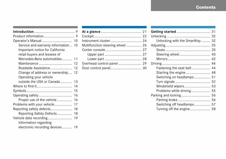
Getting started ................................... 31Unlocking ............................................. 32
Unlocking with the SmartKey ......... 32Adjusting .............................................. 35
Seats .............................................. 35Steering wheel................................ 40Mirrors............................................ 42
Driving.................................................. 44Fastening the seat belt ................... 44Starting the engine ......................... 48Switching on headlamps................. 51Turn signals .................................... 52Windshield wipers........................... 53Problems while driving.................... 55
Parking and locking.............................. 56Parking brake ................................. 56Switching off headlamps................. 57Turning off the engine..................... 58
uction .......................................... 9t information................................ 9or’s Manual ............................... 10vice and warranty information .. 10ortant notice for California il buyers and lessees of
rcedes-Benz automobiles .......... 11intenance .................................. 12dside Assistance ...................... 12nge of address or ownership.... 12
erating your vehicle side the USA or Canada............ 13 to find it .................................... 14ls............................................... 15ing safety .................................. 16per use of the vehicle ............... 16ms with your vehicle.................. 17ing safety defects...................... 18orting Safety Defects ............... 18 data recording......................... 19rmation regarding
ctronic recording devices .......... 19
At a glance .......................................... 21Cockpit................................................. 22Instrument cluster ................................ 24Multifunction steering wheel ................ 26Center console ..................................... 27
Upper part ...................................... 27Lower part ...................................... 28
Overhead control panel ........................ 29Door control panel................................ 30

Contents
Safety aOccupan
Air bSeatChild
Panic alActivDeac
Driving sABSBASESP.
Anti-theImmAnti-Tow-
ighting ............................................. 110Exterior lamp switch .................... 110Combination switch ..................... 114Cornering fog lamps*................... 114Hazard warning flasher ................ 116Interior lighting ............................ 117
strument cluster ............................. 119Instrument cluster illumination .... 119Coolant temperature gauge ......... 120Trip odometer .............................. 121Tachometer.................................. 121Outside temperature indicator ..... 121
ontrol system .................................. 123Multifunction display.................... 123Multifunction steering wheel........ 124Menus.......................................... 126Standard display menu ................ 128AUDIO menu ................................ 129NAV* menu.................................. 131Vehicle status message memory menu............................................ 132Settings menu.............................. 133Trip computer menu..................... 151TEL menu* ................................... 153
nd Security ........................... 59t safety................................... 60
ags .......................................... 61 belts ....................................... 66ren in the vehicle.................... 70
arm* ........................................ 80ating ....................................... 80tivating ................................... 80afety systems......................... 81................................................ 81................................................ 82................................................ 83ft systems................................ 86obilizer..................................... 86theft alarm system*................ 86away alarm* ........................... 87
Controls in detail ............................... 89Locking and unlocking ......................... 90
SmartKey ....................................... 90Opening the doors from the inside. 94Opening the trunk lid ..................... 95Closing the trunk lid ....................... 95Trunk lid emergency release .......... 96Automatic central locking .............. 97Locking and unlocking from the inside ............................................. 98
Seats ................................................. 100Easy-entry/exit feature* .............. 100Removing and installing front seat head restraints............................. 102Rear seat head restraints ............. 103Seat heating*............................... 106
Memory function* ............................. 107Storing positions into memory ..... 108Recalling positions from memory. 108Storing exterior rear view mirror parking position ........................... 109
L
In
C

Contents
ManuaShi
AutomOnGeaGeaAutDriEm(Lim
Good vHeaReaSunRea
ClimatDeasysSetAdjvolDefAir Air Reaadj
Audio system...................................... 195Audio and telephone, operation.... 195Operating safety ........................... 195Operating and display elements ... 196Button and soft key operation ...... 198Operation...................................... 198Radio operation ............................ 203Introduction to satellite radio* (USA only)..................................... 208CD mode....................................... 213GSM network phones ................... 220TDMA or CDMA network phones .. 227Emergency calls “911” ................. 234
Power windows .................................. 237Opening and closing the windows 237Synchronizing power windows...... 240
l transmission ......................... 157fting into reverse..................... 158atic transmission*................... 159e-touch gearshifting................. 160r ranges ................................. 161r selector lever position ......... 162omatic shift program .............. 164ving tips................................... 165ergency operation p Home Mode) ...................... 166
isibility .................................... 167dlamp cleaning system* ........ 167r view mirrors......................... 167 visors .................................... 169r window defroster ................. 170
e control .................................. 172ctivating the climate control
tem ......................................... 175ting the temperature............... 175usting air distribution and ume ......................................... 176rosting .................................... 177recirculation mode.................. 177conditioning............................ 179r passenger compartment
ustable air vents...................... 180
Automatic climate control* ................ 182Deactivating the automatic climate control system ................. 185Setting the temperature................ 185Adjusting air distribution............... 186Adjusting air volume ..................... 187Defrosting ..................................... 188Maximum cooling MAXCOOL........ 188Air recirculation mode .................. 189Charcoal filter ............................... 191Air conditioning............................. 192Residual heat and ventilation (available on automatic climate control panel design A only).......... 193Rear passenger compartment adjustable air vents....................... 194
Contents
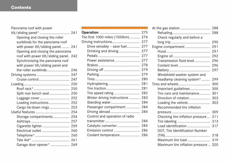
Panoramtilt/slidi
Opensunbwith Openroof Syncwith the r
Driving sCruis
LoadingRoofSplitLuggLoadCarg
Useful feStoraAshtCigaElectTelepTele Gara
t the gas station .............................. 288Refueling...................................... 288Check regularly and before a long trip ....................................... 290
ngine compartment ......................... 291Hood ............................................ 291Engine oil ..................................... 292Transmission fluid level................ 296Coolant level ................................ 296Battery ......................................... 297Windshield washer system and headlamp cleaning system*......... 299
ires and wheels................................ 300Important guidelines .................... 300Tire care and maintenance........... 301Direction of rotation..................... 303Loading the vehicle ...................... 303Recommended tire inflation pressure....................................... 309Checking tire inflation pressure ... 311Tire labeling ................................. 313Load identification ....................... 317DOT, Tire Identification Number (TIN) ............................................. 318Maximum tire load ....................... 319Maximum tire inflation pressure .. 320
a roof with power ng panel* .............................. 241ing and closing the roller linds for the panorama roof power tilt/sliding panel ........ 241ing and closing the panorama
with power tilt/sliding panel . 242hronizing the panorama roof power tilt/sliding panel and oller sunblinds....................... 246ystems ................................. 247e control............................... 247.............................................. 250 rack*.................................... 250 rear bench seat .................... 250age cover .............................. 252ing instructions..................... 252o tie-down rings .................... 253atures .................................. 254ge compartments................. 254
rays ....................................... 257rette lighter ........................... 259rical outlet ............................ 260hone*................................... 260
Aid* ...................................... 261ge door opener* ................... 269
Operation ......................................... 275The first 1000 miles (1500km) .......... 276Driving instructions............................ 277
Drive sensibly – save fuel............. 277Drinking and driving ..................... 277Pedals .......................................... 277Power assistance ......................... 277Brakes.......................................... 278Driving off .................................... 279Parking......................................... 279Tires ............................................. 280Hydroplaning................................ 281Tire traction.................................. 281Tire speed rating .......................... 282Winter driving instructions ........... 283Standing water............................. 284Passenger compartment .............. 284Driving abroad.............................. 284Control and operation of radio transmitter ................................... 284Catalytic converter....................... 285Emission control .......................... 286Coolant temperature.................... 286
A
E
T

Contents
UniStaTireTireRot
WinterWinBloSno
MainteCleserMaexcCalserResser
VehicleCle
Replacing wiper blades ...................... 393Removing...................................... 393Installing ....................................... 393
Flat tire............................................... 394Preparing the vehicle .................... 394Mounting the spare wheel ............ 394
Battery ............................................... 401Disconnecting the battery ............ 402Removing the battery ................... 402Charging and reinstalling battery.. 402Reconnecting the battery ............. 403
Jump starting...................................... 404Towing the vehicle.............................. 406
Installing towing eye bolt .............. 409Fuses.................................................. 410
Aids for changing fuses ................ 410Main fuse box in passenger compartment ................................ 411Fuse box in engine compartment . 411Fuse box in trunk.......................... 412
form Tire Quality Grading ndards (U.S. vehicles) ............. 320 ply material ........................... 322 and loading terminology........ 323ating tires ............................... 326 driving .................................... 328ter tires .................................. 328ck heater (Canada only) .......... 329w chains................................. 329nance...................................... 330aring the maintenancevice indicator........................... 331intenance service term eeded ..................................... 331ling up the maintenance vice indicator........................... 331etting the maintenance vice indicator........................... 332 care....................................... 333aning and care of the vehicle .. 333
Practical hints .................................. 339What to do if … ................................... 340
Lamps in instrument cluster ......... 340Lamp in center console................. 345Vehicle status messages in the multifunction display..................... 347
Where will I find ...? ............................ 373First aid kit.................................... 373Vehicle tool kit.............................. 373Spare wheel .................................. 375
Unlocking/locking in an emergency... 377Unlocking the vehicle.................... 377Locking the vehicle ....................... 379Fuel filler flap ................................ 379Manually unlocking the gear selector lever ................................ 380
Opening/closing in an emergency ..... 381Panorama roof with power tilt/sliding panel* ......................... 381
Replacing SmartKey batteries ............ 382SmartKey ...................................... 383
Replacing bulbs .................................. 384Bulbs............................................. 384Replacing bulbs for front lamps .... 386Replacing bulbs for rear lamps ..... 390
Contents
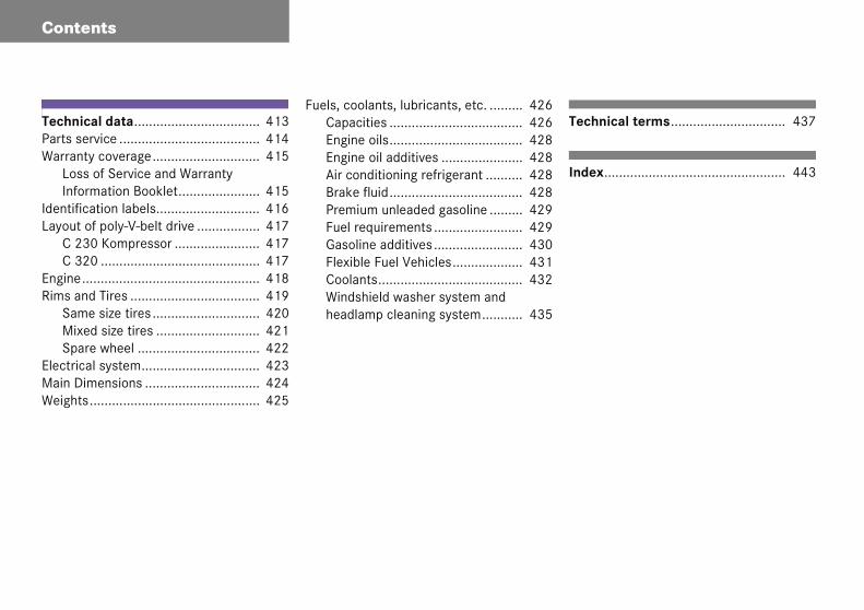
TechnicParts seWarrant
LossInfor
IdentificLayout o
C 23C 32
Engine..Rims an
SamMixeSpar
ElectricaMain DimWeights
echnical terms............................... 437
dex................................................. 443
al data.................................. 413rvice ...................................... 414y coverage............................. 415 of Service and Warranty mation Booklet...................... 415ation labels............................ 416f poly-V-belt drive ................. 4170 Kompressor ....................... 4170 ........................................... 417.............................................. 418d Tires ................................... 419e size tires ............................. 420d size tires ............................ 421e wheel ................................. 422l system................................ 423ensions ............................... 424
.............................................. 425
Fuels, coolants, lubricants, etc. ......... 426Capacities .................................... 426Engine oils.................................... 428Engine oil additives ...................... 428Air conditioning refrigerant .......... 428Brake fluid.................................... 428Premium unleaded gasoline ......... 429Fuel requirements ........................ 429Gasoline additives ........................ 430Flexible Fuel Vehicles................... 431Coolants....................................... 432Windshield washer system and headlamp cleaning system........... 435
T
In

9
Product information
�
Introduction
Plebe
WeMepaby
Wethesu
Genuine Mercedes-Benz parts as well as conversion parts and accessories approved by us are available at an autho-rized Mercedes-Benz Center where you will receive comprehensive information, also on permissible technical modifications, and where proper installation will be performed.
Produase obst inter
recomrcedes
rts and us for y
have tir relia
itability
ct informationserve the following in your own est:
mend using genuine -Benz parts as well as conversion accessories explicitly approved our vehicle model.
ested these parts to determine bility, safety and special for Mercedes-Benz vehicles.
We are unable to make an assessment for other products and therefore cannot be held responsible for them, even if in indi-vidual cases an official approval or authori-zation by governmental or other agencies should exist. Use of such parts and acces-sories could adversely affect the safety, performance or reliability of your vehicle. Please do not use them.
Introduction
a
e u ce
rveonl.thr
for
he
oral. eres
ervice and warranty information
he Service and Warranty Information ooklet contains detailed information bout the warranties covering your ercedes-Benz, including:
New Car Limited Warranty,
Emission System Warranty,
Emission Performance Warranty,
California, Maine, Massachusetts, and Vermont Emission Control System Warranty (California, Maine, Massachusetts, and Vermont only),
State Warranty Enforcement Laws (Lemon Laws).
10
Oper
This Opdeal ofread itwith th
For youof the structimanuaage to or otheure to the Me
Your veequipmTherefoptionvehiclethe oprized Mdemon
tor’s Manual
rator’s Manual contains a great seful information. We urge you to arefully and familiarize yourself vehicle before driving.
own safety and longer service life hicle, we urge you to follow the in-s and warnings contained in this
Ignoring them could result in dam-e vehicle or personal injury to you
s. Vehicle damage caused by fail-llow instructions is not covered by cedes-Benz Limited Warranty.
icle may have some or all of the nt described in this manual. e, you may find explanations for equipment not installed in your If you have any questions about ation of any equipment, an autho-rcedes-Benz Center will be glad to trate the proper procedures.
We continuously strive to improve our product, and ask for your understanding that we reserve the right to make changes in design and equipment. Therefore, infor-mation, illustrations and descriptions in this Operator’s Manual might differ from your vehicle.
Optional equipment is also described in this manual, including operating instruc-tions wherever necessary. Since they are special-order items, the descriptions and illustrations herein may vary slightly from the actual equipment of your vehicle.
If there are any equipment details that are not shown or described in this Operator’s Manual, an authorized Mercedes-Benz Center will be glad to inform you of correct care and operating procedures.
The Operator’s Manual and Maintenance Booklet are important documents and should be kept with the vehicle.
S
TBaM
�
�
�
�
�
11
Introduction
Operator’s Manual
Imporretail bMerce
Under a replaof the Mercedauthorfix onefunctioits expnumberiod ofthe veh18 000on the occursattemplesseeoccurs
(3) the vehicle is out of service by reason of repair of the same or different sub-stantial defects or malfunctions for a cumulative total of more than 30 calendar days.
Written notification should be sent to us, not a dealer, at Mercedes-Benz USA, LLC, Customer Assistance Center, One Mercedes Drive, Montvale, NJ 07645-0350.
tant notice for California uyers and lessees of
des-Benz automobiles
California law you may be entitled to cement of your vehicle or a refund purchase price or lease price, if es-Benz USA, LLC and/or its
ized repair or service facilities fail to or more substantial defects or mal-ns in the vehicle that are covered by ress warranty after a reasonable r of repair attempts. During the pe- 18 months from original delivery of icle or the accumulation of miles (approximately 29 000 km)
odometer of the vehicle, whichever first, a reasonable number of repair ts is presumed for a retail buyer or
if one or more of the following :
(1) the same substantial defect or mal-function results in a condition that is likely to cause death or serious bodily injury if the vehicle is driven, that de-fect or malfunction has been subject to repair two or more times, and you have directly notified Mercedes-Benz USA, LLC in writing of the need for its repair,
(2) the same substantial defect or mal-function of a less serious nature than category (1) has been subject to repair four or more times and you have direct-ly notified us in writing of the need for its repair, or

12
Introduction
Opera
Mainten
The Mainnecessabe perfo
Always hyou wherized MeThe servvice in t
hange of address or ownership
you change your address, be sure to end in the “Change of Address Notice” und in the Service and Warranty Informa-
on Booklet, or simply call the ercedes-Benz Customer Assistance enter (in the USA) at -800-FOR-MERCedes, or Customer Ser-ice (in Canada) at 1-800-387-0100. It is in our own interest that we can contact you hould the need arise.
you sell your Mercedes, please leave all terature with the vehicle to make it avail-ble to the next operator.
you bought this vehicle used, be sure to end in the “Notice of Purchase of Used ar” found in the Service and Warranty In-rmation Booklet, or call the ercedes-Benz Customer Assistance Cen-r (in the USA) at 1-800-FOR-MERCedes,
r Customer Service (in Canada) at -800-387-0100.
tor’s Manual
ance
tenance Booklet describes all the ry maintenance work which should rmed at regular intervals.
ave the Maintenance Booklet with n you take the vehicle to an autho-rcedes-Benz Center for service. ice advisor will record each ser-he booklet for you.
Roadside Assistance
The Mercedes-Benz Roadside Assistance Program provides factory-trained technical help in the event of a breakdown. Calls to the toll-free Roadside Assistance number
1-800-FOR-MERCedes (in the USA)1-800-387-0100 (in Canada)
will be answered by Mercedes-Benz Cus-tomer Assistance Representatives 24 hours a day, 365 days a year.
For additional information refer to the Mercedes-Benz Roadside Assistance Pro-gram Brochure in your vehicle literature portfolio.
C
IfsfotiMC1vys
Iflia
IfsCfoMteo1

13
Introduction
Operator’s Manual
Operaoutsid
If you peign co
� serma
� unlalythecat
� gaser ocau
ting your vehicle e the USA or Canada
lan to operate your vehicle in for-untries, please be aware that:
vice facilities or replacement parts y not be readily available,
eaded gasoline for vehicles with cat-tic converters may not be available; use of leaded fuels will damage the alysts,
oline may have a considerably low-ctane rating, and improper fuel can se engine damage.
Certain Mercedes-Benz models are avail-able for delivery in Europe under our Euro-pean Delivery Program. For details, consult an authorized Mercedes-Benz Center or write to:
In the USA:
Mercedes-Benz USA, LLCEuropean Delivery DepartmentOne Mercedes DriveMontvale, NJ 07645-0350
In Canada:
Mercedes-Benz Canada, Inc.European Delivery Department98 Vanderhoof AvenueToronto, Ontario M4G 4C9

Introduction
e
em, oat
an
ouls
our
ctdebo
a
ous
echnical data
ll important technical data for your vehi-le can be found in this section.
dexes
he glossary provides explanations of the ost important technical terms.
he table of contents and the index are de-igned to help you find information quickly nd easily.
he following publications are part of your ehicle documentation:
this Operator’s Manual
the Maintenance Booklet
eparate operating instructions will be rovided as required depending on the quipment options installed in your vehi-le.
14
Wher
This Opvide cofor youhas itsinform
At a gl
Here ycontrodriver’s
Getting
Here yneed fothis seMerceing or
Safety
Here yfeature
to find it
rator’s Manual is designed to pro-prehensive support information
the vehicle operator. Each section wn reference color so you can find ion quickly.
ce
will find an overview of all the that can be operated from the seat.
started
will find all the information you your first drive. You should read ion first if this is your first s-Benz vehicle or if you are rent-rrowing this vehicle.
nd Security
will find descriptions of the safety of your vehicle.
Controls in detail
Here you will find detailed information about the equipment installed in your vehi-cle. This section expands on the “Getting started” section and also describes techni-cal innovations. If you are already familiar with the basic functions of your vehicle, this section will be of particular interest to you.
Operation
Here you will find all the information you need for the proper operation of your vehi-cle.
Practical hints
This section provides fast assistance for dealing with problems you may encounter.
T
Ac
In
Tm
Tsa
Tv
�
�
Spec
15
Introduction
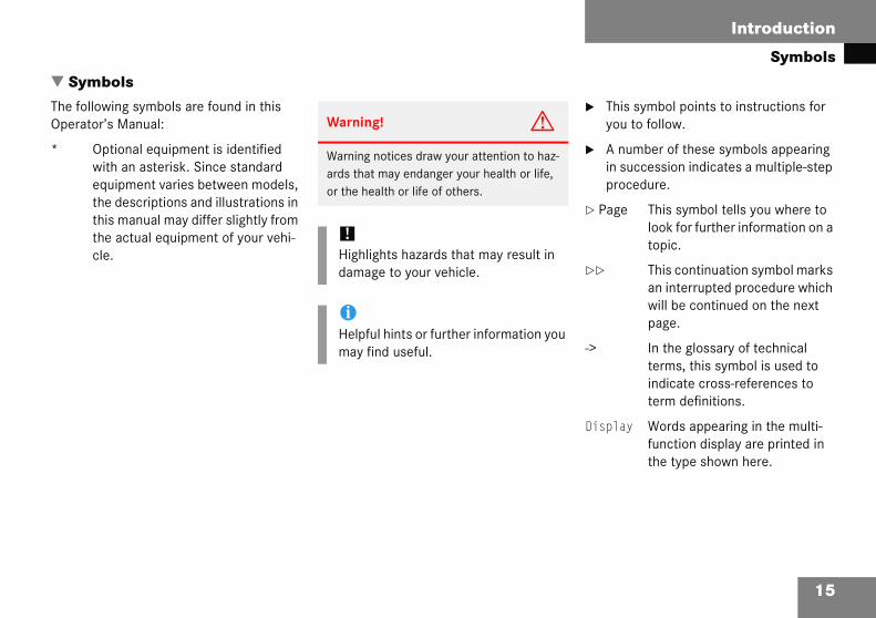
Symbols
�ThOp
*
� This symbol points to instructions for you to follow.
� A number of these symbols appearing in succession indicates a multiple-step procedure.
� Page This symbol tells you where to look for further information on a topic.
�� This continuation symbol marks an interrupted procedure which will be continued on the next page.
-> In the glossary of technical terms, this symbol is used to indicate cross-references to term definitions.
Display Words appearing in the multi-function display are printed in the type shown here.
Symbe followerator’
Opwiteqthethithecle
olsing symbols are found in this
s Manual:
tional equipment is identified h an asterisk. Since standard uipment varies between models, descriptions and illustrations in
s manual may differ slightly from actual equipment of your vehi-.
Warning! G
Warning notices draw your attention to haz-ards that may endanger your health or life, or the health or life of others.
!Highlights hazards that may result in damage to your vehicle.
iHelpful hints or further information you may find useful.

Introduction
a
roper use of the vehicle
roper use of the vehicle requires that you re familiar with the following information nd rules:
the safety precautions in this manual
the “Technical data” section in this manual
traffic rules and regulations
motor vehicle laws and safety stan-dards
i
imon thn
ce Eime
n paon
imee
se n
Warning! G
Various warning labels are attached to your vehicle. These warning labels are intended to make you and others aware of various risks. You should not remove any of these warning labels unless explicitly instructed to do so by information on the label itself. Removal of any of these labels may cause you and others to be unaware of certain risks which may result in an accident and/or personal injury.
16
Oper
Warn
Work compcausethe veterconprodutems.ously vehicl
See afor recomp
Othervehiclthe op
Someenginer tur
ting safety
P
Paa
�
�
�
�
ng! G
properly carried out on electronic ents and associated software could
hem to cease functioning. Because icle’s electronic components are in-ected, any modification made may an undesired effect on other sys-
lectronic malfunctions could seri-pair the operating safety of your
.
authorized Mercedes-Benz Center irs or modifications to electronic ents.
proper work or modifications on the could also have a negative impact on rating safety of the vehicle.
afety systems only function while the is running. You should therefore nev-off the engine while driving.
Warning! G
Heavy blows against the vehicle underbody or tires/wheels, for example when running over an obstacle, road debris or a pothole, may cause serious damage and impair the operating safety of your vehicle. If you feel a sudden significant vibration or ride distur-bance, or you suspect that damage to your vehicle has occurred, you should turn on your hazard warning flashers, carefully slow down, and drive with caution to an area which is a safe distance from the road.
Inspect the vehicle underbody and tires/wheels for possible damage. If the ve-hicle appears unsafe, have it towed to the nearest authorized Mercedes-Benz Center or other qualified maintenance or repair fa-cility for further inspection or repairs.

17
Introduction
Problems with your vehicle
ProblIf you s affect its safe operation, we urge you to immed and corrected if required. If the matter is not han r management, or if necessary contact us at one
In the
CustomMercedOne MMontva
In Can
CustomMerced98 VanToront
ems with your vehiclehould experience a problem with your vehicle, particularly one that you believe mayiately contact an authorized Mercedes-Benz Center to have the problem diagnosed dled to your satisfaction, please discuss the problem with the Mercedes-Benz Centeof the following addresses:
USA:
er Assistance Centeres-Benz USA, LLC
ercedes Drivele, NJ 07645-0350
ada:
er Relations Departmentes-Benz Canada, Inc.derhoof Avenueo, Ontario M4G 4C9
Introduction
rt
Ulo ral Regulations, Part 575 pursuant to the na
ti
e or death, you should immediately inform ti s-Benz USA, LLC.
A ty defect exists in a group of vehicles, it d dual problems between you, your dealer, c
ta r 366-0123 in Washington, D.C. area) or o: obtain other information about motor s
18
Repo
For theThe fol“Natio
Repor
If you bthe Na
If NHTSmay oror Mer
To conwrite tvehicle
ing safety defects
SA only:wing text is published as required of manufacturers under Title 49, Code of U.S. Fedel Traffic and Motor Vehicle Safety Act of 1966”.
ng Safety Defects
lieve that your vehicle has a defect which could cause a crash or could cause injuryonal Highway Traffic Safety Administration (NHTSA) in addition to notifying Mercede
receives similar complaints, it may open an investigation, and if it finds that a safeer a recall and remedy campaign. However, NHTSA cannot become involved in indiviedes-Benz USA, LLC.
ct NHTSA, you may either call the Auto Safety Hotline toll-free at 1-888-327-4236 (o NHTSA, U.S. Department of Transportation, Washington, D.C. 20590. You can alsoafety from the Hotline.

19
Introduction
Vehicle data recording
Vehic
Informelectro
(Includ
Please and, if equipped with the Tele Aid system, may tr
This in ntinuously improve vehicle safety. Daimle
� for
� wit
� in r
� for ganization and/or
� as
Please tion that may be recorded or transmitted via tha
le data recording
ation regarding nic recording devices
ing notice pursuant to California Code § 9951)
note that your vehicle is equipped with devices that can record vehicle systems dataansmit some data in certain accidents.
formation helps, for example, to diagnose vehicle systems after a collision and to corChrysler may access the information and share it with others
safety research or vehicle diagnosis purposes
h the consent of the vehicle owner or lessee
esponse to an official request by law enforcement or other government agency
use in dispute resolution involving DaimlerChrysler, its affiliates or sales/service or
otherwise required or permitted by law.
check the Tele Aid subscription service agreement for details regarding the informat system.

20

21
At a glance
Cockpit
Instrument cluster
Multifunction steering wheel
Center console
Overhead control panel
Door control panel
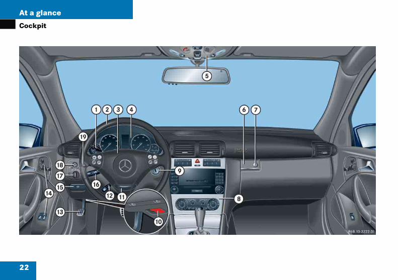
At a glance
p
22
Cock
it
23
At a glance
Cockpit
I
1 C
2 Mw
3 H
4 I
5 O
6 G
Item Page
f Parking brake release 50
g Combination switch
� Turn signals 52
� High beam 52
� Windshield wipers 53
h Exterior lamp switch 51110
j Exterior rear view mirror adjustment
42
k Headlamp washer switch* 167
tem Page
ruise control lever 247
ultifunction steering heel
26124
orn
nstrument cluster 24119
verhead control panel 29
love box lid release 254
Item Page
7 Glove box lock 254
8 Center console 27
9 Starter switch 33
a Hood lock release 291
b Steering wheel adjustment handle (manual)
41
c Steering wheel adjustment stalk (electrical)*
41
d Parking brake pedal 50, 56
e Door control panel 30

At a glance
m
24
Instru
ent cluster
25
At a glance
Instrument cluster
It
1 S
v
;
3
B
2 L
3 M
T
M
G
Item Page
ú Engine malfunction indicator lamp, USA only
342
± Engine malfunction indicator lamp, Canada only
342
6 Fuel gauge with:
Fuel reserve warning lamp 344
4 Fuel filler cap location indicator: The fuel filler cap is on the rear right-hand side.
7 Coolant temperature gauge 120
8 Reset button for:
� Resetting trip odometer 121
� Resetting individual settings
135
� Instrument cluster illumination
119
em Page
peedometer with:
Electronic Stability Program (ESP) warning lamp
83343
Brake warning lamp, USA only
5056
341
Brake warning lamp, Canada only
5056
341
Low beam headlamp indicator lamp
51110
Left turn signal indicator lamp
52
ultifunction display with:
rip odometer 121
ain odometer 123
ear selector lever position 49162
Item Page
Program mode 164
Status indicator(outside temperature/ digital speedometer)
121138
Digital clock 123139
4 K Right turn signal indicator lamp
52
5 Tachometer with:
- Antilock Brake System (ABS) indicator lamp
81340
< Seat belt telltale 66344
1 Supplemental restraint system indicator lamp
60344
A High beam headlamp indicator lamp
51114

At a glance
fu
Item Page
4 Moving within a menu:Press button
j for next display
k for previous display
5 Menu systems:Press button
è for next menu
ÿ for previous menu
26
Multi
nction steering wheelItem Page
1 Multifunction display in speedometer
123
Operating control system
123
2 Selecting the submenu or setting the volume:Press button
æ up/to increase
ç down/to decrease
3 Telephone*:Press button
s to take a call
t to end a call

27
At a glance
Center console
�Up
Centeper pa
r consolert Item Page
1 Seat heater*, driver‘s side 106
2 ESP control switch 83
3 Hazard warning flasher switch – switching on/off
116
4 Central locking switch 98
Central unlocking switch 98
5 Tow-away alarm switch* 87
Anti-theft alarm system indicator lamp*
86
6 Seat heater*, passenger side
106
7 Front passenger front air bag off indicator lamp
76
8 Audio system 195
or
COMAND* (see separate operating instructions)
9 Climate control 172
Automatic climate control* 182
28
At a glance
Center
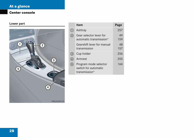
Lower p
console
art Item Page
1 Ashtray 257
2 Gear selector lever for automatic transmission*
49159
Gearshift lever for manual transmission
48157
3 Cup holder 256
4 Armrest 255
5 Program mode selector switch for automatic transmission*
164
29
At a glance
Overhead control panel
�
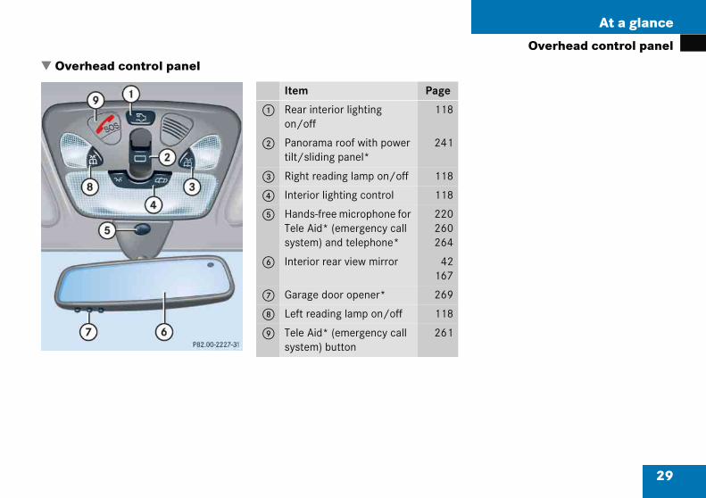
Overh ead control panelItem Page
1 Rear interior lighting on/off
118
2 Panorama roof with power tilt/sliding panel*
241
3 Right reading lamp on/off 118
4 Interior lighting control 118
5 Hands-free microphone for Tele Aid* (emergency call system) and telephone*
220260264
6 Interior rear view mirror 42167
7 Garage door opener* 269
8 Left reading lamp on/off 118
9 Tele Aid* (emergency call system) button
261

At a glance
c
30
Door
ontrol panelItem Page
1 Door handle 94
2 Memory function* (for storing seat, exterior rear view mirror and steering wheel settings)
107
3 Seat adjustment* 38
4 Switches for opening/clos-ing door windows
237

31
Getting started
Unlocking
Adjusting
Driving
Parking and locking
Getting started
ewi
p g
rn satar
k
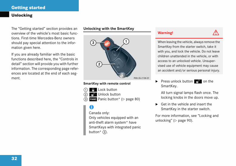
Press unlock button Πon the SmartKey.
All turn signal lamps flash once. The locking knobs in the doors move up.
Get in the vehicle and insert the SmartKey in the starter switch.
or more information, see “Locking and nlocking” (� page 90).
Warning! G
When leaving the vehicle, always remove the SmartKey from the starter switch, take it with you, and lock the vehicle. Do not leave children unattended in the vehicle, or with access to an unlocked vehicle. Unsuper-vised use of vehicle equipment may cause an accident and/or serious personal injury.
32
The “Govervietions. Fshouldmation
If you afunctiodetail”informences ment.
Unloc
tting started” section provides an of the vehicle’s most basic func-
rst-time Mercedes-Benz owners ay special attention to the infor-iven here.
e already familiar with the basic s described here, the “Controls in ection will provide you with further ion. The corresponding page refer-e located at the end of each seg-
ing
Unlocking with the SmartKey
SmartKey with remote control
1 ‹ Lock button2 Œ Unlock button3  Panic button* (� page 80)
�
�
Fu
iCanada only:Only vehicles equipped with an anti-theft alarm system* have SmartKeys with integrated panic button* 3.
33
Getting started
Unlocking
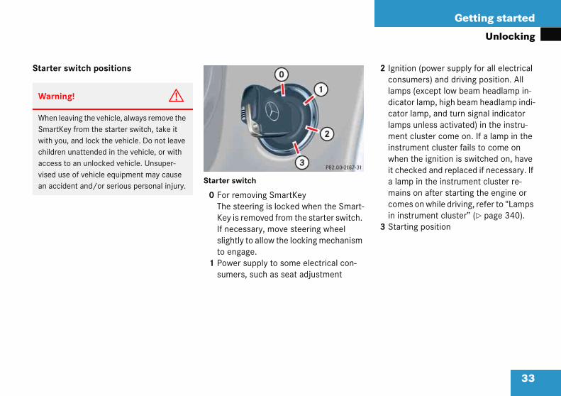
Starte 2 Ignition (power supply for all electrical consumers) and driving position. All lamps (except low beam headlamp in-dicator lamp, high beam headlamp indi-cator lamp, and turn signal indicator lamps unless activated) in the instru-ment cluster come on. If a lamp in the instrument cluster fails to come on when the ignition is switched on, have it checked and replaced if necessary. If a lamp in the instrument cluster re-mains on after starting the engine or comes on while driving, refer to “Lamps in instrument cluster” (� page 340).
3 Starting position
Warn
WhenSmartwith ychildraccesvised an ac
r switch positions
Starter switch
0 For removing SmartKey The steering is locked when the Smart-Key is removed from the starter switch. If necessary, move steering wheel slightly to allow the locking mechanism to engage.
1 Power supply to some electrical con-sumers, such as seat adjustment
ing! G
leaving the vehicle, always remove the Key from the starter switch, take it ou, and lock the vehicle. Do not leave en unattended in the vehicle, or with s to an unlocked vehicle. Unsuper-use of vehicle equipment may cause cident and/or serious personal injury.

34
Getting started
Unlock
iWhedicatbeambeamturn vatedon. Tsysteand headheadnal ingo o
iVehiThe Sfromselec
ing
n you switch on the ignition, the in-or and warning lamps (except low headlamp indicator lamp, high headlamp indicator lamp, and
signal indicator lamps unless acti-) in the instrument cluster come his indicates that the respective ms are operational. The indicator
warning lamps (except low beam lamp indicator lamp, high beam lamp indicator lamp, and turn sig-dicator lamps if activated) should
ut when the engine is running.
cles with automatic transmission: martKey can only be removed
the starter switch with the gear tor lever in position P.
!If the SmartKey cannot be turned in the starter switch, the battery may not be sufficiently charged.
� Check the battery and charge it if necessary (� page 401).
� Get a jump start (� page 404).
To prevent accelerated battery dis-charge and a possible dead battery, al-ways remove the SmartKey from the starter switch when the engine is not in operation.

35
Getting started
Adjusting
�
Se
Thor eq
W
Artt
W
DAt
Nbtuua
Warning! G
According to accident statistics, children are safer when properly restrained in the rear seating positions than in the front seat-ing position. Thus, we strongly recommend that children be placed in the rear seats whenever possible. Regardless of seating position, children 12 years old and under must be seated and properly secured in an appropriate infant, or toddler restraint, or booster seat recommended for the size and weight of the child. For additional information, see “Children in the vehicle” (� page 70).
A child’s risk of serious or fatal injuries is significantly increased if the child restraints are not properly secured in the vehicle and/or the child is not properly secured in the child restraint.
Adjus
ats
e seatselectricuipmen
arning
ll seat, hear viewening ofhe vehic
arning
o not addjusting
he drive
ever ridack in ahis can bnder thender it, bdomen
ting
can be adjusted either manually ally, depending on the vehicle’s t.
! G
ead restraint, steering wheel, and mirror adjustments, as well as fas- seat belts, must be done before le is put into motion.
! G
just the driver’s seat while driving. the seat while driving could cause
r to lose control of the vehicle.
e in a moving vehicle with the seat n excessively reclined position as e dangerous. You could slide seat belt in a collision. If you slide the belt would apply force at the or neck.
That could cause serious or fatal injuries. The seat back and seat belts provide the best restraint when the wearer is in a nearly upright position and belts are properly posi-tioned on the body. Your seat must be adjusted so that you can correctly fasten your seat belt (� page 44).
Never place hands under the seat or near any moving parts while a seat is being ad-justed.
Warning! G
When leaving the vehicle, always remove the SmartKey from the starter switch, take it with you, and lock the vehicle.
Even with the SmartKey removed from the starter switch, the power seats* can be op-erated when the respective door is open. Therefore, do not leave children unattended in the vehicle, or with access to an unlocked vehicle. Unsupervised use of vehicle equip-ment may cause an accident and/or serious personal injury.

36
Getting started
Adjust
Manual
1 Back2 Seat3 Seat4 Seat
eat cushion tilt
Turn handwheel 3 forward or back-ward until your upper legs are lightly supported.
eat backrest tilt
Turn handwheel 1 forward or back-ward until your arms are slightly angled when holding the steering wheel.
eat height
Pull handle 2 up to raise seat cushion.
Push handle 2 down to lower seat cushion.
ing
seat adjustment
rest tilt height cushion tilt fore and aft adjustment
Seat fore and aft adjustment
� Lift handle 4.
� Slide seat to the desired position.
� Allow handle 4 to reengage.
� Check for proper engagement before driving.
Adjust seat to a comfortable seating posi-tion that still allows you to reach the accel-erator/brake pedal safely. The position should be as far rearward as possible, consistent with ability to properly operate controls.
S
�
S
�
S
�
�
!When moving the seats, make sure that there are no items in the footwell or behind the seats. Otherwise you could damage the seats.

37
Getting started
Adjusting
Head r
1 Rel
Raising
� Mares
Head restraint tilt
Manually adjust the angle of the head re-straint.
� Push or pull on the lower edge of the head restraint cushion.
For more information, see “Seats” (� page 100).
estraint height
ease button
:
nually adjust the height of the head traint by pulling it upward.
Lowering:
� To lower the head restraint, push re-lease button 1 and press down on the head restraint.
Warning! G
For your protection, drive only with properly positioned head restraints.
Adjust head restraint so that the center of the head restraint supports the back of the head at eye level. This will reduce the poten-tial for injury to the head and neck in the event of an accident or similar situation.
Do not drive the vehicle without the seat head restraints. Head restraints are intend-ed to help reduce injuries during an acci-dent.
iAdjust the head restraint in such away that it is as close to the head as possible.
38
Getting started
Adjust
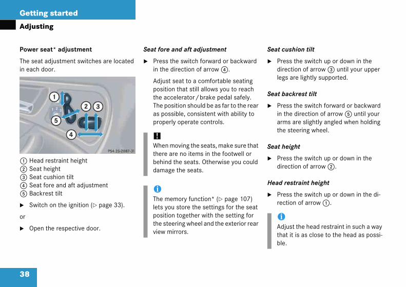
Power s
The seatin each
1 Head2 Seat3 Seat4 Seat5 Back
� Swit
or
� Open
eat cushion tilt
Press the switch up or down in the direction of arrow 3 until your upper legs are lightly supported.
eat backrest tilt
Press the switch forward or backward in the direction of arrow 5 until your arms are slightly angled when holding the steering wheel.
eat height
Press the switch up or down in the direction of arrow 2.
ead restraint height
Press the switch up or down in the di-rection of arrow 1.
iAdjust the head restraint in such a way that it is as close to the head as possi-ble.
ing
eat* adjustment
adjustment switches are located door.
restraint height height cushion tilt fore and aft adjustmentrest tilt
ch on the ignition (� page 33).
the respective door.
Seat fore and aft adjustment
� Press the switch forward or backward in the direction of arrow 4.
Adjust seat to a comfortable seating position that still allows you to reach the accelerator/brake pedal safely. The position should be as far to the rear as possible, consistent with ability to properly operate controls.
S
�
S
�
S
�
H
�
!When moving the seats, make sure that there are no items in the footwell or behind the seats. Otherwise you could damage the seats.
iThe memory function* (� page 107) lets you store the settings for the seat position together with the setting for the steering wheel and the exterior rear view mirrors.

39
Getting started
Adjusting
Folding front seat backrest forward
1 Release lever2 Seat belt presenter
Warn
For yopositi
Adjusthe hehead tial foevent
Do nohead ed to dent. i
In addition to the front seat backrests, the front seat cushions can also be shifted forward to permit easy access to the rear whenever the seat is located in the rear half of its adjustment range. Swivel backrest forward by pulling the release lever until the seat moves in a combined forward and upward move-ment.
Head restraint tilt
Manually adjust the angle of the head re-straint.
� Push or pull on the lower edge of the head restraint cushion.
For more information, see “Seats” (� page 100).
ing! G
ur protection, drive only with properly oned head restraints.
t head restraint so that the center of ad restraint supports the back of the
at eye level. This will reduce the poten-r injury to the head and neck in the of an accident or similar situation.
t drive the vehicle without the seat restraints. Head restraints are intend-help reduce injuries during an acci-

40
Getting started
Adjust
Folding
� Pivot
� Pull the s
Vehicles
� If nedownforw
teering wheel
iVehirestrdown
Warning! G
Do not adjust the steering wheel while driving. Adjusting the steering wheel while driving, or driving without the steering wheel adjustment locked could cause the driver to lose control of the vehicle.
When leaving the vehicle, always remove the SmartKey from the starter switch, take it with you, and lock the vehicle.
Even with the SmartKey removed from the starter switch, the electrical steering wheel adjustment feature* can be operated when the driver’s door is open. Therefore, do not leave children unattended in the vehicle, or with access to an unlocked vehicle. Unsu-pervised use of vehicle equipment may cause an accident and/or serious personal injury.
ing
backrest forward
seat belt presenter 2 down.
release lever 1 forward and fold eat backrest forward.
with manual seat adjustment:
cessary, press the head restraint ward while tilting the backrest
ard.
Folding backrest back
� Fold and press the backrest rearward until it engages in driving position.
Vehicles with manual seat adjustment:
� If necessary, pull the head restraint out while tilting the seat back.
For more information, see “Seats” (� page 100).
S
cles with power seat*: The head aints will automatically move .
iVehicles with power seat*: The head restraint returns to its previous posi-tions.

41
Getting started
Adjusting
Steeri
1 Han
� To han
� Mopos
� To haneng
Theloc
Steering wheel adjustment, electrical*
The stalk for steering wheel adjustment is located on the steering column (lower left).
1 Adjusting steering column, in or out2 Adjusting steering column, up or down
� Switch on the ignition (� page 33).
or
� Open the driver’s door.
ng wheel adjustment, manual
dle
unlock the steering column, pull dle 1 out until its stop limit.
ve steering wheel to the desired ition.
lock the steering column, push dle 1 all the way in until it ages.
steering wheel is once again ked into position.
� Make sure the steering wheel is securely locked by trying to move it up and down, and in and out before driving off.
Make sure your legs can move freely and that all the displays (inclusive malfunction and indicator lamps) on the instrument cluster are clearly visible.
Warning! G
Only adjust the steering wheel with the vehi-cle at a standstill and make sure the steer-ing wheel is securely locked in place before driving off.
Driving without the steering wheel adjust-ment locked may cause an unexpected steering wheel movement which could cause the driver to lose control of the vehi-cle. Make sure the steering wheel is secure-ly locked by trying to move it up and down, and in and out before driving off.
42
Getting started
Adjust
Adjustin
� Movetion steeyour
Adjustin
� Moveof ar
Makand funcstrum
terior rear view mirror
Manually adjust the interior rear view mirror.
or more information, see “Rear view mir-rs” (� page 167).
xterior rear view mirrors
iThe mlets ying wthe smirro
Warning! G
Exercise care when using the passen-ger-side exterior rear view mirror. The mirror surface is convex (outwardly curved surface for a wider field of view). Objects in mirror are closer than they appear. Check your in-side rear view mirror or glance over your shoulder before changing lanes.
ing
g steering column in or out
stalk forward or back in the direc-of arrow 1 until a comfortable ring wheel position is reached with arms slightly bent at the elbow.
g steering column, up or down
stalk up or down in the direction row 2.
e sure your legs can move freely that all the displays (inclusive mal-tion and indicator lamps) on the in-
ent cluster are clearly visible.
Mirrors
Adjust the interior and exterior rear view mirrors before driving so that you have a good view of the road and traffic condi-tions.
In
�
Fro
E
emory function* (� page 107) ou store the setting for the steer-heel together with the setting for eat position and exterior rear view rs.
Warning! G
In the case of an accident, liquid electrolyte may escape the mirror housing if the mirror glass breaks.
Electrolyte has an irritating effect. Do not al-low the liquid to come into contact with eyes, skin, clothing, or respiratory system. In case it does, immediately flush affected area with water, and seek medical help if necessary.
!Electrolyte drops coming into contact with the vehicle paint finish can only be completely removed while in their liquid state and by applying plenty of water.
43
Getting started
Adjusting
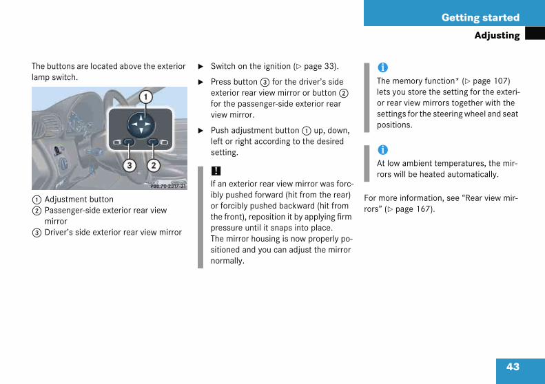
The bulamp s
1 Adj2 Pas
mir3 Dri
For more information, see “Rear view mir-rors” (� page 167).
iThe memory function* (� page 107) lets you store the setting for the exteri-or rear view mirrors together with the settings for the steering wheel and seat positions.
iAt low ambient temperatures, the mir-rors will be heated automatically.
ttons are located above the exterior witch.
ustment buttonsenger-side exterior rear view rorver’s side exterior rear view mirror
� Switch on the ignition (� page 33).
� Press button 3 for the driver’s side exterior rear view mirror or button 2 for the passenger-side exterior rear view mirror.
� Push adjustment button 1 up, down, left or right according to the desired setting.
!If an exterior rear view mirror was forc-ibly pushed forward (hit from the rear) or forcibly pushed backward (hit from the front), reposition it by applying firm pressure until it snaps into place. The mirror housing is now properly po-sitioned and you can adjust the mirror normally.

Getting started
i
i
t eivfo
g j
s.r
i
s wrln
Warning! G
According to accident statistics, children are safer when properly restrained in the rear seating positions than in the front seat-ing position. Thus, we strongly recommend that children be placed in the rear seats. Regardless of seating position, children 12 years old and under must be seated and properly secured in an appropriate infant or toddler restraint, or booster seat recom-mended for the size and weight of the child. For additional information, see “Children in the vehicle” (� page 70).
A child’s risk of serious or fatal injuries is significantly increased if the child restraints are not properly secured in the vehicle and/or the child is not properly secured in the child restraint.
44
Drivin
Fasten
Warn
Do nowell. Bthe drance
Durinthe obpedalaccele
Warn
Alwayoff. Alproperear a
g
ng the seat belt
ng! G
lay any objects in the driver’s foot- careful that floor mats or carpets in er’s footwell have sufficient clear-r the pedals.
sudden driving or braking maneuvers ects could get caught between the You could then no longer brake or ate.
ng! G
fasten your seat belt before driving ays make sure your passengers are y restrained, even those sitting in the d pregnant women.
Failure to wear and properly fasten and po-sition your seat belt greatly increases your risk of injuries and their likely severity in an accident. You and your passengers should always wear seat belts.
If you are ever in an accident, your injuries can be considerably more severe without your seat belt properly buckled. Without your seat belt buckled, you are much more likely to hit the interior of the vehicle or be ejected from it. You can be seriously injured or killed.
In the same crash, the possibility of injury or death is lessened if you are wearing your seat belt. The air bags can only provide the protection they were designed to afford if the occupants are using their seat belts (� page 66).
45
Getting started
Driving
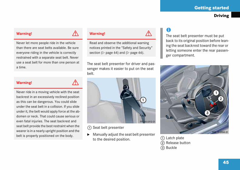
1 Latch plate2 Release button3 Buckle
Warn
Neverthan teveryrestrause a a time
Warn
Neverbackras thiunderunderdomeeven fseat bwearebelt is
iThe seat belt presenter must be put back to its original position before lean-ing the seat backrest toward the rear or letting someone enter the rear passen-ger compartment.
The seat belt presenter for driver and pas-senger makes it easier to put on the seat belt.
1 Seat belt presenter
� Manually adjust the seat belt presenter to the desired position.
ing! G
let more people ride in the vehicle here are seat belts available. Be sure one riding in the vehicle is correctly ined with a separate seat belt. Never seat belt for more than one person at .
ing! G
ride in a moving vehicle with the seat est in an excessively reclined position s can be dangerous. You could slide the seat belt in a collision. If you slide it, the belt would apply force at the ab-n or neck. That could cause serious or atal injuries. The seat backrest and elt provide the best restraint when the r is in a nearly upright position and the properly positioned on the body.
Warning! G
Read and observe the additional warning notices printed in the “Safety and Security” section (� page 64) and (� page 66).

46
Getting started
Drivin
� Withfrom
� Placeacrolap p
� Pushit clic
� If nea snuup.
aising
Slide belt outlet upward.
owering
Press button 1 and slide belt outlet downward.
g
a smooth motion, pull the belt the seat belt presenter.
the shoulder portion of the belt ss the top of your shoulder and the ortion across your hips.
latch plate 1 into buckle 3 until ks.
cessary, tighten the lap portion to g fit by pulling shoulder portion
Seat belt height adjustment
1 Release button
R
�
L
�

47
Getting started
Driving
Proper
� Do
� Adjporto tnotshoarmthe
� Poson acr
� Plaupr
� Nevper
Warning! G
Do not pass belts over sharp edges. They could tear.
Do not allow the belt to get caught in the door or in the seat adjustment mechanism. This could damage the belt.
Never attempt to make modifications to seat belts. This could impair the effective-ness of the belts.
Do not bleach or dye seat belts as this may severely weaken them. In a crash they may not be able to provide adequate protection.
Damaged seat belts or belts that were highly stressed in an accident must be replaced. Contact an authorized Mercedes-Benz Center.
use of seat belts
not twist the belt when fastening.
ust seat belt so that the shoulder tion is located as close as possible he middle of the shoulder (it should touch the neck). Never pass the ulder portion of the belt under your . For this purpose, you can adjust
height of the belt outlet.
ition the lap belt as low as possible your hips (over hip joint) and not oss the abdomen.
ce the seat backrest in a nearly ight position.
er use a seat belt for more than one son at a time.
� Do not fasten a seat belt around a per-son and another object at the same time. When using a seat belt to secure infant or toddler restraints or children in booster seats, always follow the child seat manufacturer's instructions.
� Check your seat belt periodically dur-ing travel to ensure that it is properly positioned.
� Make sure the seat belt is always fitted snugly. Take special care of this when wearing loose clothing.
48
Getting started
Drivin
Starting tarting
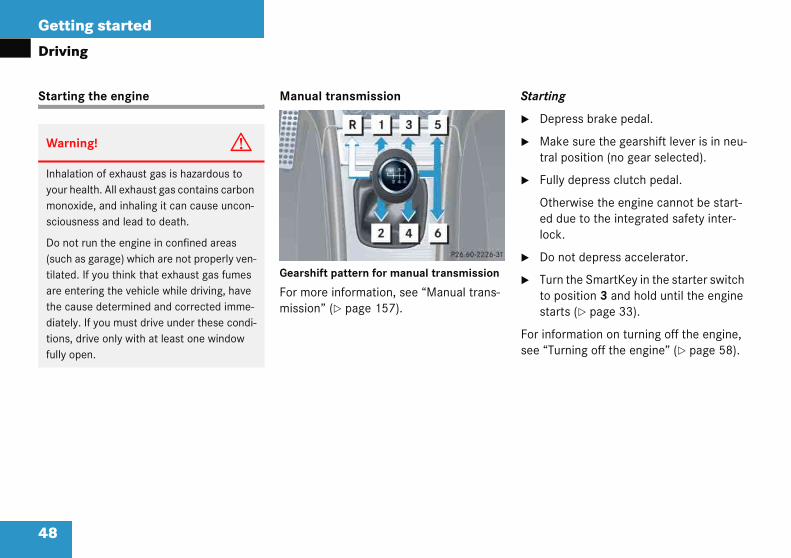
Depress brake pedal.
Make sure the gearshift lever is in neu-tral position (no gear selected).
Fully depress clutch pedal.
Otherwise the engine cannot be start-ed due to the integrated safety inter-lock.
Do not depress accelerator.
Turn the SmartKey in the starter switch to position 3 and hold until the engine starts (� page 33).
or information on turning off the engine, ee “Turning off the engine” (� page 58).
Warni
Inhalatiyour hemonoxisciousn
Do not (such atilated. are entthe caudiately.tions, dfully op
g
the engine Manual transmission
Gearshift pattern for manual transmission
For more information, see “Manual trans-mission” (� page 157).
S
�
�
�
�
�
Fs
ng! G
on of exhaust gas is hazardous to alth. All exhaust gas contains carbon de, and inhaling it can cause uncon-ess and lead to death.
run the engine in confined areas s garage) which are not properly ven-If you think that exhaust gas fumes ering the vehicle while driving, have se determined and corrected imme- If you must drive under these condi-rive only with at least one window en.
49
Getting started
Driving
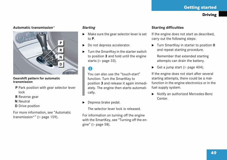
Autom
Gearshtransm
P Parloc
R RevN NeuD Dri
For motransm
Starting difficulties
If the engine does not start as described, carry out the following steps:
� Turn SmartKey in starter to position 0 and repeat starting procedure.
Remember that extended starting attempts can drain the battery.
� Get a jump start (� page 404).
If the engine does not start after several starting attempts, there could be a mal-function in the engine electronics or in the fuel supply system.
� Notify an authorized Mercedes-Benz Center.
atic transmission*
ift pattern for automatic ission
k position with gear selector lever kerse geartral
ve position
re information, see “Automatic ission*” (� page 159).
Starting
� Make sure the gear selector lever is set to P.
� Do not depress accelerator.
� Turn the SmartKey in the starter switch to position 3 and hold until the engine starts (� page 33).
� Depress brake pedal.
The selector lever lock is released.
For information on turning off the engine with the SmartKey, see “Turning off the en-gine” (� page 58).
iYou can also use the “touch-start” function. Turn the SmartKey to position 3 and release it again immedi-ately. The engine then starts automati-cally.
50
Getting started
Drivin
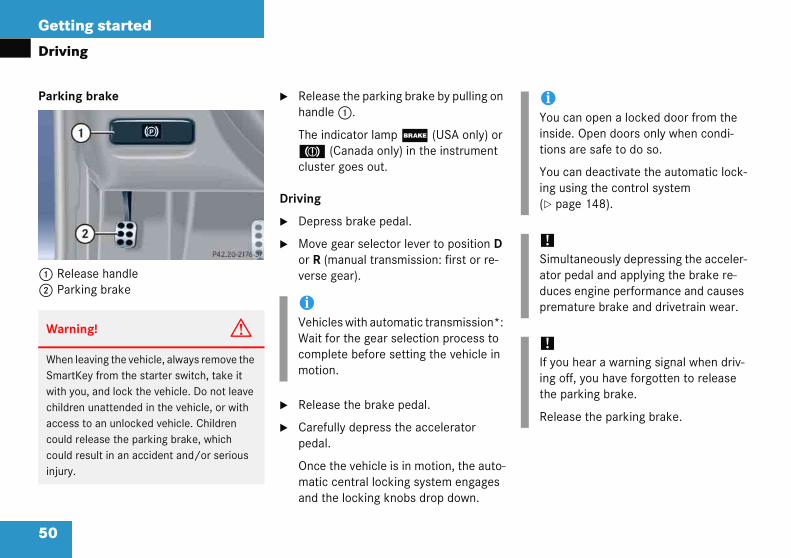
Parking
1 Rele2 Park
Warni
When leSmartKwith yochildrenaccess could recould reinjury.
iYou can open a locked door from the inside. Open doors only when condi-tions are safe to do so.
You can deactivate the automatic lock-ing using the control system (� page 148).
!Simultaneously depressing the acceler-ator pedal and applying the brake re-duces engine performance and causes premature brake and drivetrain wear.
!If you hear a warning signal when driv-ing off, you have forgotten to release the parking brake.
Release the parking brake.
g
brake
ase handleing brake
� Release the parking brake by pulling on handle 1.
The indicator lamp ; (USA only) or 3 (Canada only) in the instrument cluster goes out.
Driving
� Depress brake pedal.
� Move gear selector lever to position D or R (manual transmission: first or re-verse gear).
� Release the brake pedal.
� Carefully depress the accelerator pedal.
Once the vehicle is in motion, the auto-matic central locking system engages and the locking knobs drop down.
ng! G
aving the vehicle, always remove the ey from the starter switch, take it u, and lock the vehicle. Do not leave unattended in the vehicle, or with to an unlocked vehicle. Children lease the parking brake, which sult in an accident and/or serious
iVehicles with automatic transmission*: Wait for the gear selection process to complete before setting the vehicle in motion.

51
Getting started
Driving
After asion shThis allits ope
Switching on headlamps
For more information on headlamps, see “Lighting” (� page 110).
Low beam headlamps
The exterior lamp switch is located on the dashboard to the left of the steering wheel.
Exterior lamp switch
1 Off2 Low beam headlamps on
Warn
On sliin ordresultcle covent t
!VehPlaposstotran
cold start, the automatic transmis-ifts at a higher engine revolution. ows the catalytic converter to reach rating temperature earlier.
For more information on driving, see “Driv-ing instructions” (� page 277).
ing! G
ppery road surfaces, never downshift er to obtain braking action. This could in drive wheel slip and reduced vehi-ntrol. Your vehicle’s ABS will not pre-his type of loss of control.
icles with automatic transmission*: ce the gear selector lever in ition P or R only when the vehicle is pped in order to avoid damaging the smission.
!Do not run cold engine at high engine speeds. Running a cold engine at high speeds may shorten the service life of the engine.
Warning! G
Vehicles with automatic transmission*: It is dangerous to shift the gear selector lever out of P or N if the engine speed is higher than idle speed. If your foot is not firmly on the brake pedal, the vehicle could acceler-ate quickly forward or in reverse. You could lose control of the vehicle and hit someone or something. Only shift into gear when the engine is idling normally and when your right foot is firmly on the brake pedal.

52
Getting started
Drivin
� Turnposit
The llampcom
High be
The comleft of th
Combina
1 High2 High
Press combination switch in direction of arrow 1 or 2.
The corresponding turn signal indicator lamp L or K in the instrument cluster flashes.
The combination switch resets auto-matically after major steering wheel movements.
iTo signal minor directional changes, such as changing lanes, press combi-nation switch only to point of resis-tance and release. The corresponding turn signal will flash three times.
g
the exterior lamp switch to ion B.
ow beam headlamp indicator B in the instrument cluster
es on (� page 24).
am
bination switch is located on the e steering column.
tion switch
beam beam flasher
� Push the combination switch in direction of arrow 1.
The high beam headlamp indicator lamp A in the instrument cluster comes on (� page 24).
For more information on headlamps, see “Combination switch” (� page 114).
Turn signals
The combination switch is located on the left of the steering column.
Combination switch
1 Turn signals, right2 Turn signals, left
�
53
Getting started
Driving
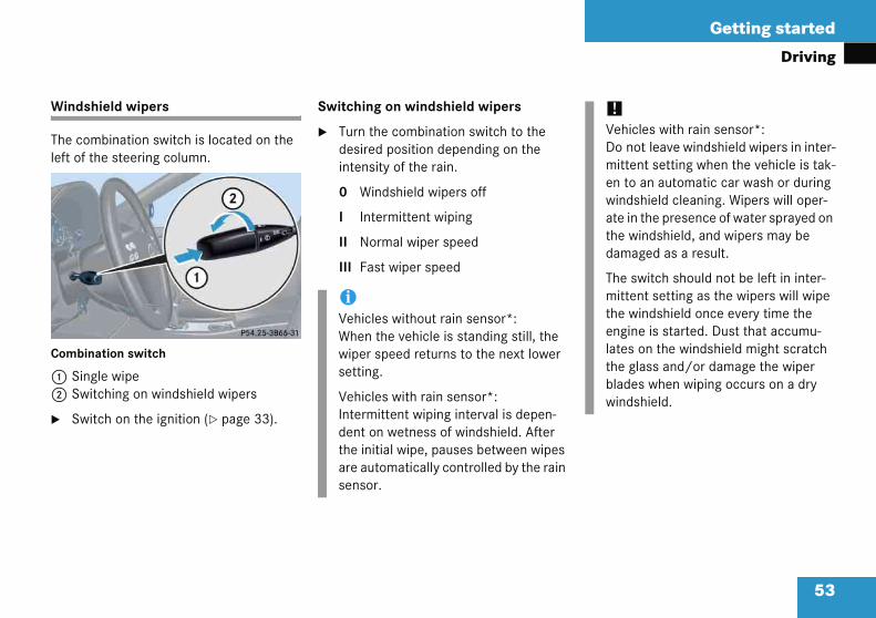
Winds
The coleft of
Combin
1 Sin2 Sw
� Sw
!Vehicles with rain sensor*: Do not leave windshield wipers in inter-mittent setting when the vehicle is tak-en to an automatic car wash or during windshield cleaning. Wipers will oper-ate in the presence of water sprayed on the windshield, and wipers may be damaged as a result.
The switch should not be left in inter-mittent setting as the wipers will wipe the windshield once every time the engine is started. Dust that accumu-lates on the windshield might scratch the glass and/or damage the wiper blades when wiping occurs on a dry windshield.
hield wipers
mbination switch is located on the the steering column.
ation switch
gle wipeitching on windshield wipers
itch on the ignition (� page 33).
Switching on windshield wipers
� Turn the combination switch to the desired position depending on the intensity of the rain.
0 Windshield wipers off
I Intermittent wiping
II Normal wiper speed
III Fast wiper speed
iVehicles without rain sensor*: When the vehicle is standing still, the wiper speed returns to the next lower setting.
Vehicles with rain sensor*: Intermittent wiping interval is depen-dent on wetness of windshield. After the initial wipe, pauses between wipes are automatically controlled by the rain sensor.

54
Getting started
Drivin
Intermi
� Set t
Single w
� Presarrow
The wwitho
iInterthe vis op
!If anything blocks the windshield wip-ers (leaves, snow, etc.), switch them off immediately.
� For safety reasons, withdraw SmartKey from starter switch before attempting to remove any blockage.
� Remove blockage.
� Turn the windshield wipers on again.
If windshield wipers fail to function at all in switch position I,
� set the combination switch to the next highest wiper speed
� have the windshield wipers checked at the nearest authorized Mercedes-Benz Center
g
ttent wiping
he wiper switch to position I.
ipe
s switch briefly in the direction of 1.
indshield wipers wipe one time ut washer fluid.
Wiping with windshield washer fluid
� Push switch in the direction of arrow 1 past the resistance point.
The windshield wipers operate with washer fluid.
For information on filling up the washer reservoir, see “Windshield washer system and headlamp cleaning system*” (� page 299).
mittent wiping is interrupted when ehicle is at a standstill and a door ened.

55
Getting started
Driving
Proble
The en
� An
� Theope
� Unbthe
� Giv
� Havautsoo
In case of accident
If the vehicle is leaking gasoline:
� Do not start the engine under any cir-cumstances.
� Notify local fire and/or police authori-ties.
If the extent of the damage cannot be determined:
� Notify an authorized Mercedes-Benz Center.
If no damage can be determined on the
� major assemblies
� fuel system
� engine mount:
� Start the engine in the usual manner.
ms while driving
gine runs erratically and misfires
ignition cable may be damaged.
engine electronics may not be rating properly.
urned gasoline may have entered catalytic converter and damaged it.
e very little gas.
e the problem repaired by an horized Mercedes-Benz Center as n as possible.
The coolant temperature is over 248°F (120°C)
The coolant is too hot and is no longer cooling the engine.
� Stop the vehicle as soon as possible and turn off the engine. Allow engine and coolant to cool.
� Check the coolant level and add cool-ant if necessary (� page 296).

Getting started
n
vvh
arking brake
Release handleParking brake
Step firmly on parking brake 2.
When the engine is running, the indica-tor lamp ; (USA only) or 3 (Canada only) in the instrument cluster will be illuminated.
i
lenin.
i
hr a
d is
56
Parki
You haYou hayour ve
Warn
VehicWait uremovswitchthe Sm
Warn
With tpowesystemin minefforthicle.
g and locking
e now completed your first drive. e properly stopped and parked icle. End your drive as follows.
P
12
�
ng! G
s with manual transmission:til the vehicle is stationary before g the SmartKey from the starter
The vehicle cannot be steered when artKey is removed.
ng! G
e engine not running, there is no ssistance for the brake and steering
. In this case, it is important to keep that a considerably higher degree of necessary to brake and steer the ve-
Warning! G
Do not park this vehicle in areas where com-bustible materials such as grass, hay or leaves can come into contact with the hot exhaust system, as these materials could be ignited and cause a vehicle fire.
To reduce the risk of personal injury as a re-sult of vehicle movement, before turning off the engine and leaving the vehicle always:
� Keep right foot on brake pedal.
� Firmly depress parking brake pedal.
� Move the gear selector lever to position P (manual transmission: first or reverse gear).
� Slowly release brake pedal.
� When parked on an incline, turn front wheels towards road curb.
� Turn the SmartKey in the starter switch to position 0 and remove the SmartKey from the starter switch.
� Take the SmartKey with you and lock the vehicle when leaving.

57
Getting started
Parking and locking
Switching off headlamps
� Turn the exterior lamp switch to M (� page 51).
For more information on headlamps, see “Lighting” (� page 110).
Warn
Gettinselect(manuis daninclinefirst oyour vpeopl
Alwayshiftinfirst o
Whentowar
ing! G
g out of your vehicle with the gear or lever not fully engaged in position P al transmission: first or reverse gear) gerous. Also, when parked on an , position P (manual transmission:
r reverse gear) alone may not prevent ehicle from moving, possibly hitting e or objects.
s set the parking brake in addition to g to position P (manual transmission: r reverse gear).
parked on an incline, turn front wheels ds the road curb.
Warning! G
When leaving the vehicle, always remove the SmartKey from the starter switch, take it with you, and lock the vehicle. Do not leave children unattended in the vehicle, or with access to an unlocked vehicle. Children could release the parking brake and/or move the gear selector lever from position P (manual transmission: into neutral), either of which could result in an accident and/or se-rious injury.
58
Getting started
Parkin
Turning
� Placepositor re
� Turnto pofromThe i
After exiting the vehicle, press the lock button ‹ on the SmartKey (� page 32).
With the hood, trunk and all doors closed, all turn signal lamps flash three times. The locking knobs in the doors move down. The anti-theft alarm sys-tem* is armed.
or more information, see “Locking and nlocking” (� page 90).
iAlwation trans
On sward
iVehiThe Sfromselec
Warning! G
When leaving the vehicle, always remove the SmartKey from the starter switch, take it with you, and lock the vehicle. Do not leave children unattended in the vehicle, or with access to an unlocked vehicle. Unsuper-vised use of vehicle equipment may cause an accident and/or serious personal injury.
g and locking
off the engine
the gear selector lever in ion P (manual transmission: first verse gear).
the SmartKey in the starter switch sition 0 and remove the SmartKey the starter switch.mmobilizer is activated.
� Press the seat belt release button (� page 44).
Allow the retractor to completely rewind the seat belt by guiding the latch plate.
�
Fu
ys set the parking brake in addi-to shifting to position P (manual mission: first or reverse gear).
lopes, turn the front wheels to-s the road curb.
cles with automatic transmission*: martKey can only be removed
the starter switch with the gear tor lever in position P.
iWith the SmartKey removed and the driver’s door open, a warning sounds if the vehicle’s exterior lamps are not switched off.
Warning! G
To prevent possible personal injury, always keep hands and fingers away from the door openings when closing the doors. Be espe-cially careful when small children are around.
Before closing doors, make sure there is no possibility of someone getting caught in a door during closing.

59
Safety and Security
Occupant safety
Panic alarm*
Driving safety systems
Anti-theft systems

Safety and Security
p
st n
in
t
ld
eT
m
b
bs
et
he SRS system conducts a self-test when e ignition is switched on and in regular tervals while the engine is running. This cilitates early detection of malfunctions.
he 1 indicator lamp in the instrument luster comes on when the ignition is witched on and goes out no later than a w seconds after the engine has been
tarted.
he SRS components are in operational adiness if the 1 indicator lamp is not
t when the engine is running.
malfunction in the system has been etected if the 1 indicator lamp:
fails to go out after approximately four seconds after the engine was started
does not come on at all
comes on after the engine was started or while driving.
60
Occu
In this portancompo
Restra
� Sea
� Chi
� Low(LA
Supple
� Air
� Airsen
� Emsea
ant safety
ection you will learn the most im-facts about the restraint system ents of the vehicle.
t system with
belts (� page 66)
restraints (� page 77)
r anchors and tethers for children CH) (� page 78)
ental Restraint System (SRS) with
ags (� page 61)
ag control unit (with crash ors)
rgency tensioning device (ETD) for belts (� page 69)
Air bag system components with
� 56 indicator lamp (� page 76)
� Front passenger seat with Occupant Classification System (OCS) (� page 73)
As independent systems, their protective functions work in conjunction with each other.
TthinfaTcsfes
Treli
Ad
�
�
�
iFor information on infants and children traveling with you in the vehicle and restraint systems for infants and chil-dren, see “Children in the vehicle” (� page 70).

61
Safety and Security
Occupant safety
Air bagsWarn
In thecomeon at malfurecomMercethe synot dewhichor it messari
Warning! G
Air bags are designed to reduce the poten-tial of injury and fatality in certain frontal im-pacts (front air bags) or side impacts (side impact air bags and head protection window curtain air bags). However, no system avail-able today can totally eliminate injuries and fatalities.
The deployment of the air bags temporarily releases a small amount of dust from the air bags. This dust, however, is neither injurious to your health, nor does it indicate a fire in the vehicle. The dust might cause some tem-porary breathing difficulty for people with asthma or other breathing trouble. To avoid this, you may wish to get out of the vehicle as soon as it is safe to do so. If you have any breathing difficulty but cannot get out of the vehicle after the air bag inflates, then get fresh air by opening a window or door.
ing! G
event that the 1 indicator lamp s on during driving or does not come all, the SRS self-check has detected a nction. For your safety, we strongly mend that you visit an authorized des-Benz Center immediately to have stem checked; otherwise the SRS may ploy when needed in an accident, could result in serious or fatal injury, ight deploy unexpectedly and unnec-ly which could also result in injury.
In addition, improper work on the SRS creates a risk of rendering the SRS inopera-tive or causing unintended air bag deploy-ment. Work on the SRS must therefore only be performed by qualified technicians. Con-tact an authorized Mercedes-Benz Center.
If it is necessary to modify an air bag system to accommodate a person with disabilities, contact your local authorized Mercedes-Benz Center or call our Customer Assistance Center at 1-800-FOR-MERCedes (1-800-367-6372) for details.
62
Safety and Security
Occup
Warni
To reduair bagsdriver aproperlrespect
For maxcollisionwith yoyour seerly pos
Since thspeed aon steeyou at aOccupaor too cinjured force in
� Sit posbac
� Occupants, especially children, should never place their bodies or lean their heads in the area of the door or the rear side trim panel where the side impact air bag inflates. This could result in serious injuries or death should the air bag be triggered. Always sit nearly upright, properly use the seat belts and use an appropriately sized infant or toddler re-straint or booster seat recommended for the size and weight of the child.
Failure to follow these instructions can re-sult in severe injuries to you or other occupants.
If you sell your vehicle, it is important that you make the buyer aware of this safety in-formation. Be sure to give the buyer this Operator's Manual.
ant safety
ng! G
ce the risk of injury when the front inflate, it is very important for the nd front passenger to always be in a y seated position and to wear their ive seat belts.
imum protection in the event of a always be in normal seated position
ur back against the backrest. Fasten at belt and make sure that it is prop-itioned on your body.
e air bag inflates with considerable nd force, a proper seating and hands ring wheel position will help to keep safe distance from the air bag. nts who are unbelted, out of position lose to the air bag can be seriously by an air bag as it inflates with great the blink of an eye:
properly belted in a nearly upright ition with your back against the seat krest.
� Adjust the driver seat as far as possible rearward, still permitting proper opera-tion of vehicle controls. The distance from the center of the driver’s breast-bone to the center of the air bag cover on the steering wheel must be at least 10 in (25 cm) or more. You should be able to accomplish this by a combina-tion of adjustments to the seat and steering wheel. If you have any prob-lems, please see your authorized Mercedes-Benz Center.
� Do not lean your head or chest close to the steering wheel or dashboard.
� Keep hands on the outside of steering wheel rim. Placing hands and arms in-side the rim can increase the risk and potential severity of hand/arm injury when driver front air bag inflates.
� Adjust the front passenger seat as far as possible rearward from the dashboard when the seat is occupied.

63
Safety and Security
Occupant safety
Warn
Accidplace rear s
It shofront apossibinjurynot prto a sploy rjob.
To helfollow
(1) Onehesireth
iAir bags are designed to deploy only in certain frontal impacts (front air bags) and in side impacts (side impact and head protection window curtain air bags) which exceed preset thresholds. Only during these events will they provide their supplemental protection.
The driver and passengers should always wear their seat belts. Otherwise it is not possible for air bags to provide their supplemental protection.
In case of other types of impacts and impacts below air bag deployment thresholds, air bags will not deploy. The driver and passenger will then be protected to the extent possible by a properly fastened seat belt. A properly fastened seat belt is also needed to provide the best possible protection in a rollover.
We caution you not to rely on the pres-ence of the air bags in order to avoid wearing your seat belt.
ing! G
ent research shows that the safest for children in an automobile is in the eat.
uld be noted that with respect to both nd rear side impact air bags there is a ility for a side impact air bag related
if occupants, especially children, are operly seated or restrained when next ide impact air bag which needs to de-apidly in a side impact in order to do its
p avoid the possibility of injury, please these guidelines:
ccupants, especially children, should ver place their bodies or lean their ads in the area of the door where the
de impact air bag inflates. This could sult in serious injuries or death should e side impact air bag be deployed.
(2) Always sit nearly upright, properly use the seat belts and for children 12 years old and under, use an appropriately sized infant or toddler restraint or boost-er seat recommended for the size and weight of the child.
(3) Always wear seat belts properly.
If you believe that, even with the use of these guidelines, it would be safer for your rear seat occupants to have the rear mount-ed side impact air bags deactivated, then deactivation can be accomplished upon your written request to do so at your autho-rized Mercedes-Benz Center at an additional cost.
Please contact your local authorized Mercedes-Benz Center or call our Customer Assistance Center at 1-800-FOR-MERCedes (1-800-367-6372) for details.
64
Safety and Security
Occup
It is iyourployetionivehicmen
� No modifications of any kind may be made to any components or wiring of the SRS. This includes changing or re-moving any component or part of the SRS, the installation of additional trim material, badges etc. over the steering wheel hub, passenger front air bag cov-er, door trim panels, or door frame trims, and installation of additional elec-trical/electronic equipment on or near SRS components and wiring. Keep area between air bags and occupants free from objects (e.g. packages, purses, umbrellas, etc.).
� Do not hang items such as coat hangers from the coat hooks or handles over the door. These items may turn into projec-tiles and cause head and other injuries when curtain air bag is deployed.
� Never place your feet on the instrument panel, dashboard, or on the seat. Always keep both feet on the floor in front of the seat.
� Air bag system components will be hot after an air bag has inflated. Do not touch.
ant safety
Safety guidelines for the seat belt, emergency tensioning device and air bag
mportant to your safety and that of passengers that you replace de-d air bags and repair any malfunc-
ng air bags to make sure that the le will continue to provide supple-
tal crash protection for occupants.Warning! G
� Damaged seat belts or belts that were highly stressed in an accident must be replaced and their anchoring points must also be checked. Only use belts in-stalled or supplied by an authorized Mercedes-Benz Center.
� Air bags and emergency tensioning de-vices (ETDs) are designed to function on a one-time-only basis. An air bag or ETD that is deployed must be replaced.
� Do not pass belts over sharp edges. They could tear.
� Do not make any modification that could change the effectiveness of the belts.
� Do not bleach or dye seat belts as this may severely weaken them. In a crash they may not be able to provide ade-quate protection.
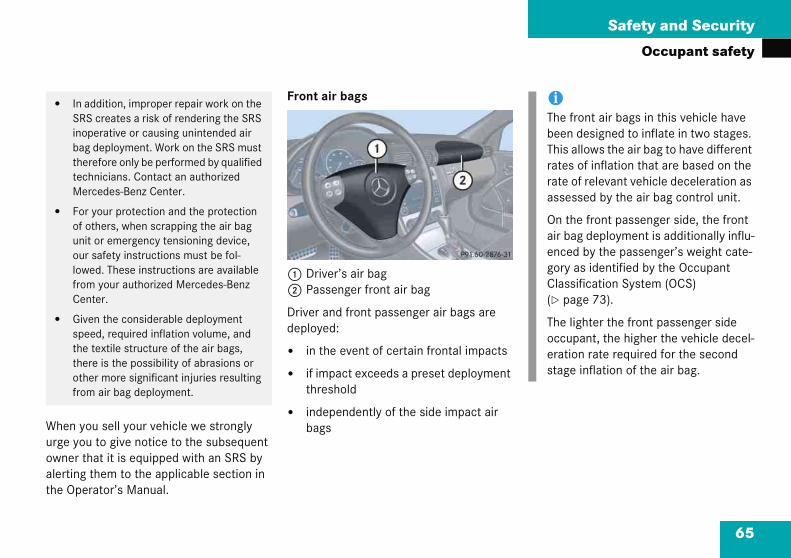
65
Safety and Security
Occupant safety
When yurge yoowner alertinthe Op
� InSRinbathteM
� FoofunoulofrC
� Gspththotfr
iThe front air bags in this vehicle have been designed to inflate in two stages. This allows the air bag to have different rates of inflation that are based on the rate of relevant vehicle deceleration as assessed by the air bag control unit.
On the front passenger side, the front air bag deployment is additionally influ-enced by the passenger’s weight cate-gory as identified by the Occupant Classification System (OCS) (� page 73).
The lighter the front passenger side occupant, the higher the vehicle decel-eration rate required for the second stage inflation of the air bag.
ou sell your vehicle we strongly u to give notice to the subsequent
that it is equipped with an SRS by g them to the applicable section in erator’s Manual.
Front air bags
1 Driver’s air bag2 Passenger front air bag
Driver and front passenger air bags are deployed:
� in the event of certain frontal impacts
� if impact exceeds a preset deployment threshold
� independently of the side impact air bags
addition, improper repair work on the S creates a risk of rendering the SRS
operative or causing unintended air g deployment. Work on the SRS must erefore only be performed by qualified chnicians. Contact an authorized ercedes-Benz Center.
r your protection and the protection others, when scrapping the air bag it or emergency tensioning device, r safety instructions must be fol-
wed. These instructions are available om your authorized Mercedes-Benz enter.
iven the considerable deployment eed, required inflation volume, and e textile structure of the air bags, ere is the possibility of abrasions or her more significant injuries resulting om air bag deployment.

66
Safety and Security
Occup
The air bwhich doment thred by th
The passdeploye
� the ssor rseng
� the 5cent
� the imen
he front passenger side impact air bag ill only deploy if the system senses that e front passenger seat is occupied.
eat belts
hen the engine is started, the seat belt lltale < illuminates to remind you and
our passengers to fasten your seat belts.
the driver’s seat belt is not fastened efore the engine is started, the seat belt lltale < illuminates and a warning
hime sounds for approximately six econds when the engine is started.
he use of seat belts and infant and child straint systems is required by law in all
0 states, the District of Columbia, the .S. territories and all Canadian provinces.
ven where this is not the case, all vehicle ccupants should have their seat belts fas-ned whenever the vehicle is in motion.
or more information, see “Fastening the eat belt” (� page 44).
ant safety
ags will not deploy in impacts not exceed the system’s deploy-esholds. You will then be protect-e fastened seat belts.
enger front air bag will only be d if:
ystem, based on OCS weight sen-eadings, senses that the front pas-er seat is occupied
6 indicator lamp in the er console is not lit (� page 76)
mpact exceeds a preset deploy-t threshold
Side impact air bags, window curtain air bags
1 Window curtain air bag2 Side impact air bags
The side impact air bags and window cur-tain air bags are deployed:
� on the impacted side of the vehicle
� in impacts exceeding a preset deploy-ment threshold
� independently of the front air bags
The side impact air bags and window cur-tain air bags are not deployed in impacts which do not exceed the system’s deploy-ment threshold.
Twth
S
Wtey
Ifbtecs
Tre5U
Eote
Fs

67
Safety and Security
Occupant safety
iFortravstradre(�
Warning! G
Never ride in a moving vehicle with the seat backrest in an excessively reclined position as this can be dangerous. You could slide under the seat belt in a collision. If you slide under it, the belt would apply force at the abdomen or neck. That could cause serious or even fatal injuries. The seat backrest and seat belt provide the best restraint when the wearer is in a nearly upright position and the belt is properly positioned on the body.
Warning! G
Never let more people ride in the vehicle than there are seat belts available. Be sure everyone riding in the vehicle is correctly restrained with a separate seat belt. Never use a seat belt for more than one person at a time.
information on infants and children eling with you in the vehicle and re-int systems for infants and chil-n, see “Children in the vehicle” page 70).
Warning! G
Always fasten your seat belt before driving off. Always make sure all of your passengers are properly restrained, even those sitting in the rear and pregnant women.
Failure to wear and properly fasten and position your seat belt greatly increases your risk of injuries and their likely severity in an accident. You and your passengers should always wear seat belts.
If you are ever in an accident, your injuries can be considerably more severe without your seat belt properly buckled. Without your seat belt buckled, you are much more likely to hit the interior of the vehicle or be ejected from it. You can be seriously injured or killed.
In the same crash, the possibility of injury or death is lessened if you are properly wearing your seat belt. Air bags can only protect as they are designed if the occupants are properly wearing their seat belts.
68
Safety and Security
Occup
Warni
Damagstresseand thechecke
Only usapprove
Do not belts. Tof the E
Do not severelnot be
Have altechnicMerced
� Never wear the shoulder belt under your arm, against your neck or off your shoul-der. In a frontal crash, your body would move too far forward. That would in-crease the chance of head and neck injuries. The belt would also apply too much force to the ribs or abdomen, which could severely injure internal organs such as your liver or spleen.
� Never wear belts over rigid or breakable objects in or on your clothing, such as eyeglasses, pens, SmartKeys etc., as these might cause injuries.
� Position the lap belt as low as possible on your hips and not across the abdo-men. If the belt is positioned across your abdomen, it could cause serious injuries in a crash.
� Never use a seat belt for more than one person at a time. Do not fasten a seat belt around a person and another per-son or other objects.
ant safety
ng! G
ed seat belts or belts that were highly d in an accident must be replaced ir anchoring points must also be d.
e seat belts which have been d by Mercedes-Benz.
make any modifications to the seat his can lead to unintended activation TDs or to failure.
bleach or dye seat belts as this may y weaken them. In a crash they may able to provide adequate protection.
l work carried out only by qualified ians. Contact an authorized es-Benz Center.
Warning! G
USE SEAT BELTS PROPERLY
� Seat belts can only work when used properly. Never wear seat belts in any other way than as described in this sec-tion, as that could result in serious inju-ries in case of an accident.
� Each occupant should wear their seat belt at all times, because seat belts help reduce the likelihood of and potential severity of injuries in accidents, includ-ing rollovers. The integrated restraint system includes SRS (driver air bag, pas-senger front air bag, side impact air bags, head protection window curtain air bags for side windows), ETD (seat belt emergency tensioning device), and front seat knee bolsters.
The system is designed to enhance the protection offered to properly belted occupants in certain frontal (front air bags and ETD) and side (side impact and window curtain air bags and ETD) im-pacts which exceed preset deployment thresholds.

69
Safety and Security
Occupant safety
In an impact, emergency tensioning devic-es remove slack from the belts. Belt force limiters reduce the force exerted by the seat belts on occupants during a crash.
� BecrofThca
� Prlashonsu
� Npakese
� Worerm
Warning! G
An emergency tensioning device (ETD) that was activated must be replaced.
When disposing of the emergency tension-ing device, our safety instructions must be followed. These are available at your autho-rized Mercedes-Benz Center.
Emergency tensioning device (ETD), seat belt force limiter
The seat belts for the front and rear seats are equipped with emergency tensioning devices and belt force limiters.
The ETD is designed to activate in the fol-lowing cases:
� in frontal or rear-end impacts exceed-ing a preset severity level
� if the restraint systems are operational and functioning correctly, see 1 indicator lamp (� page 60)
lts should not be worn twisted. In a ash, you wouldn’t have the full width the belt to distribute impact forces. e twisted belt against your body could use injuries.
egnant women should also use a p-shoulder belt. The lap belt portion ould be positioned as low as possible the hips to avoid any possible pres-re on the abdomen.
ever place your feet on the instrument nel, dashboard, or on the seat. Always ep both feet on the floor in front of the at.
hen using a seat belt to secure infant toddler restraints or children in boost- seats, always follow the child seat anufacturer's instructions.
!The ETDs for the front seats will only activate if the front seat belts are fas-tened (latch plate properly inserted into buckle).
The ETDs for the rear seats will activate with or without the respective seat belts fastened.
70
Safety and Security
Occup
Children
If an infathe vehi
� Securestrsize
� Makpropvehic
Infant aninformatrestraintauthoriz
iFor information on child seats with an-chor fittings for tether anchorages, see “Installation of infant and child re-straint systems” (� page 77).
For information on LATCH-type child seat anchors, see (� page 78).
!The use of infant or child restraints is required by law in all 50 states, the Dis-trict of Columbia, the U.S. territories and all Canadian provinces.
Infants and small children should be seated in an appropriate infant or child restraint system, properly secured by a lap/shoulder belt or, if so equipped, a top tether anchorage point and a child restraint lower anchorage system that complies with U.S. Federal Motor Vehi-cle Safety Standards 213 and 225 and Canadian Motor Vehicle Safety Stan-dards 213 and 210.2.
ant safety
in the vehicle
nt or child is traveling with you in cle:
re the child using an infant or child aint appropriate to the age and of the child.
e sure that the infant or child is erly secured at all times while the le is in motion.
d child restraint seats and ion on choosing an appropriate system can be obtained from any ed Mercedes-Benz Center.
Infant and child restraint systems
We recommend all infants and children be properly restrained at all times while the vehicle is in motion.
All lap-shoulder belts except the driver’s seat belt have special seat belt retractors for secure fastening of child restraints.
To fasten a child restraint, follow child restraint instructions for mounting. Then pull the shoulder belt out completely and let it retract. During seat belt retraction, a ratcheting sound can be heard to indicate that the special seat belt retractor is acti-vated. The belt is now locked. Push down on child restraint to take up any slack.
To deactivate, release seat belt buckle and let seat belt retract completely. The seat belt can again be used in the usual manner.
71
Safety and Security
Occupant safety
Warn
Nevervehiclbelt re
!A smastationstrures
Whsyscartureuse
Pleaffito i
� Your vehicle is equipped with air bag technology designed to turn off the front passenger front air bag in your vehicle when the OCS senses the weight of a typical 12-month-old child or less along with the weight of a standard appropri-ate child restraint on the front passen-ger seat.
� A child in a rear-facing child restraint on the front passenger seat will be seriously injured or even killed if the front passenger front air bag inflates in a collision which could occur under some circumstances, even with the air bag technology installed in your vehicle. The only means to completely eliminate this risk is to never place a child in a rear-facing child restraint in the front seat. We therefore strongly recommend that you always place a child in a rear-facing child restraint in the back seat. ��
ing! G
release the seat belt buckle while the e is in motion, since the special seat tractor will be deactivated.
tatement by the child restraint nufacturer of compliance with this ndard can be found on the instruc- label on the restraint and in the in-ction manual provided with the
traint.
en using any infant or child restraint tem, or booster seat, be sure to efully read and follow all manufac-r’s instructions for installation and .
ase read and observe warning labels xed to the inside of the vehicle and nfant or child restraints.
Warning! G
According to accident statistics, children are safer when properly restrained in the rear seating positions than in the front seat-ing position. Thus, we strongly recommend that children be placed in the rear seats whenever possible. Regardless of seating position, children 12 years old and under must be seated and properly secured in an appropriate infant or child restraint recom-mended for the size and weight of the child.
The infant or child restraint must be properly secured with the vehicle's seat belt, the seat belt and top tether strap, or lower anchors and top tether strap, fully in accordance with the child seat manufacturer's instruc-tions.
Children can be killed or seriously injured by an inflating air bag. Note the following im-portant information when circumstances re-quire you to place a child in the front passenger seat:

72
Safety and Security
Occup
� If yostracauso, cattheed.lamresstal5to mlam5remthetemreapasor eair
Children too big for a toddler restraint must ride in seats using regular seat belts. Posi-tion shoulder belt across chest and shoul-der, not face or neck. A booster seat may be necessary to achieve proper belt positioning for children from 41 lbs until they reach a height where a lap/shoulder belt fits proper-ly without a booster.
When the child restraint is not in use, remove it from the vehicle or secure it with the seat belt to prevent the child restraint from becoming a projectile in the event of an accident.
Do not leave children unattended in the vehicle, even if the children are secured in a child restraint system. Unsupervised children in a child restraint system may use vehicle equipment and may cause an acci-dent and/or serious personal injury.
��
ant safety
u must install a rear-facing child re-int on the front passenger seat be-se circumstances require you to do make sure that the 56 indi-or lamp is illuminated, indicating that front passenger air bag is deactivat- Should the 56 indicator p not illuminate or go out while the traint is installed, please check in-lation. Periodically check the
6 indicator lamp while driving ake sure the 56 indicator
p is illuminated. If the 6 indicator lamp goes out or
ains out, do not transport a child on front passenger seat until the sys- has been repaired. A child in a
r-facing child restraint on the front senger seat will be seriously injured ven killed if the front passenger front bag inflates.
� If you have to place a child in a forward-facing child restraint on the front passenger seat, move the seat as far back as possible, use the proper child restraint recommended for the age, size and weight of the child, and secure child restraint with the vehicle’s seat belt according to the child seat manufacturer's instructions. For children larger than the typical 12-month-old child, the front passenger front air bag may or may not be activat-ed (� page 74).
Warning! G
Infants and small children should never share a seat belt with another occupant. During an accident, they could be crushed between the occupant and seat belt.
A child’s risk of serious or fatal injuries is significantly increased if the child restraints are not properly secured in the vehicle and/or the child is not properly secured in the child restraint.

73
Safety and Security
Occupant safety
Occup
The Ocautomafront afied ocby weipassen
Occupnearly againsfloor topant's object armresproperweight
iThefrontheem
In the event of a collision, the air bag control unit will not allow front passenger front air bag deployment when the OCS classified the front passenger seat occupant as being up to or less than the weight of a typical 12-month-old child in a standard child re-straint or if the front passenger seat is sensed as being empty.
When the OCS senses that the front passen-ger seat occupant is classified as being up to or less than the weight of a typical 12-month-old child in a standard child re-straint, the 56 indicator lamp will il-luminate when the engine is started and remain illuminated, indicating that the front passenger front air bag is deactivated.
When the OCS senses that the front passen-ger seat is classified as being empty, the 56 indicator lamp will illuminate when the engine is started and remain illu-minated, indicating that the front passenger front air bag is deactivated. ��
ant Classification System
cupant Classification System (OCS) tically turns the front passenger
ir bag on or off based on the classi-cupant weight category determined ght sensor readings from the front ger seat.
ants must sit properly belted in a upright position with their back t the seat backrest and feet on the be correctly classified. If the occu-weight is transferred to another in the vehicle (e.g. by leaning on ts), the OCS may not be able to ly approximate the occupant’s category.
Both driver and the front passenger should always use the 56 indicator lamp as an indication of whether or not the front passenger is properly positioned.
system does not deactivate the t passenger side impact air bag,
window curtain air bag and the ergency tensioning device.
iIf your seat, including your trim cover and cushion needs to be serviced in any way, take the vehicle to your authorized Mercedes-Benz Center.
Only seat accessories approved by Mercedes-Benz may be used.
Warning! G
If the 56 indicator lamp illuminates when an adult or someone larger than a small individual is in the front passenger seat, have the front passenger re-position himself or herself in the seat until the 56 indicator lamp goes out.
More information about air bag display mes-sages (� page 349).

74
Safety and Security
Occup
When thger seaheavier12-monchild re(such athe 5for appgine is spant weremain 56
front paWith thfront pa
When thger seasomeon56
approxiis startethe froned.
Warning! G
According to accident statistics, children are safer when properly restrained in the rear seating positions than in the front seat-ing position. Thus, we strongly recommend that children be placed in the rear seats whenever possible. Regardless of seating position, children 12 years old and under must be seated and properly secured in an appropriate infant or child restraint recom-mended for the size and weight of the child.
The infant or child restraint must be properly secured with the vehicle’s seat belt, the seat belt and top tether strap, or lower anchors and top tether strap, fully in accordance with the child seat manufacturer's instruc-tions.
��
ant safety
e OCS senses that the front passen-t occupant is classified as being than the weight of a typical th-old child seated in a standard straint or as being a small individual s a young teenager or a small adult),
6 indicator lamp will illuminate roximately six seconds when the en-tarted and then, depending on occu-ight sensor readings from the seat, illuminated or go out. With the
indicator lamp illuminated, the ssenger front air bag is deactivated. e 56 indicator lamp out, the ssenger front air bag is activated.
e OCS senses that the front passen-t occupant is classified as an adult or e larger than a small individual, the
indicator lamp will illuminate for mately six seconds when the engine d and then go out, indicating that t passenger front air bag is activat-
If the 56 indicator lamp is illuminated, the front passenger front air bag is deactivated and will not be deployed.
If the 56 indicator lamp is not illumi-nated, the front passenger front air bag is activated and will be deployed:
� in the event of certain frontal impacts
� if impact exceeds a preset deployment threshold
� independently of the side impact air bags.
If the front passenger front air bag is deployed, the rate of inflation will be influenced by:
� the rate of relevant vehicle deceleration as assessed by the air bag control unit
� front passenger's weight category as identified by the Occupant Classification System (OCS).

75
Safety and Security
Occupant safety
Childran infimporrequirpasse
� Yotepawtywatge
� A thlysewstgymischthalch
� If you have to place a child in a forward-facing child restraint on the front passenger seat, move the seat as far back as possible, use the proper child restraint recommended for the age, size and weight of the child, and secure child restraint with the vehicle’s seat belt according to the child seat manufacturer's instructions. For children larger than the typical 12-month-old child, the front passenger front air bag may or may not be activat-ed (� page 74).
iDeployment of the driver front air bag does not mean that the front passenger front air bag also should have de-ployed.
en can be killed or seriously injured by lating air bag. Note the following tant information when circumstances e you to place a child in the front nger seat:
ur vehicle is equipped with air bag chnology designed to turn off the front ssenger front air bag in your vehicle
hen the system senses the weight of a pical 12-month-old child or less along ith the weight of a standard appropri-e child restraint on the front passen-r seat.
child in a rear-facing child restraint on e front passenger seat will be serious- injured or even killed if the front pas-nger front air bag inflates in a collision
hich could occur under some circum-ances, even with the air bag technolo- installed in your vehicle. The only eans to completely eliminate this risk to never place a child in a rear-facing ild restraint in the front seat. We erefore strongly recommend that you ways place a child in a rear-facing ild restraint in the back seat.
� If you must install a rear-facing child re-straint on the front passenger seat be-cause circumstances require you to do so, make sure that the 56 indi-cator lamp is illuminated, indicating that the front passenger front air bag is deac-tivated. Should the 56 indicator lamp not illuminate or go out while the restraint is installed, please check in-stallation. Periodically check the 56 indicator lamp while driving to make sure the 56 indicator lamp is illuminated. If the 56 in-dicator lamp goes out or remains out, do not transport a child on the front pas-senger seat until the system has been repaired. A child in a rear-facing child re-straint on the front passenger seat will be seriously injured or even killed if the front passenger front air bag inflates.
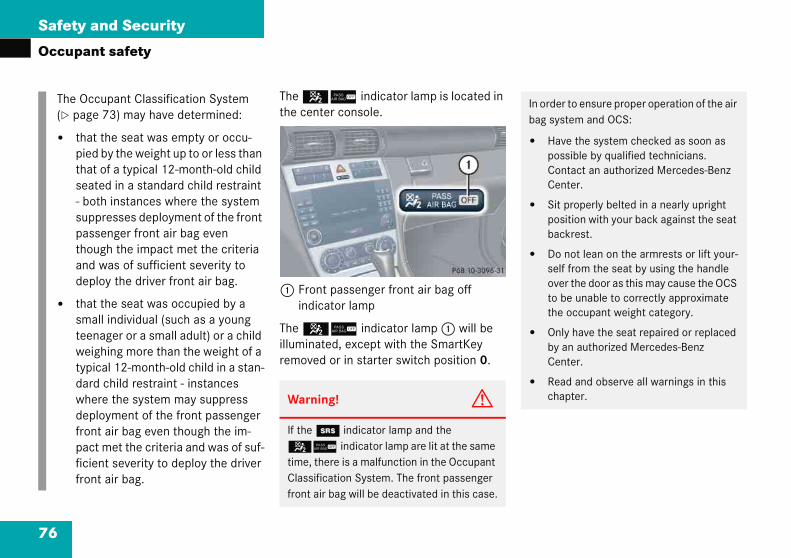
76
Safety and Security
Occup
The O(� pa
� tpts- sptad
� tstwtdwdfrpfifr
In order to ensure proper operation of the air bag system and OCS:
� Have the system checked as soon as possible by qualified technicians. Contact an authorized Mercedes-Benz Center.
� Sit properly belted in a nearly upright position with your back against the seat backrest.
� Do not lean on the armrests or lift your-self from the seat by using the handle over the door as this may cause the OCS to be unable to correctly approximate the occupant weight category.
� Only have the seat repaired or replaced by an authorized Mercedes-Benz Center.
� Read and observe all warnings in this chapter.
ant safety
The 56 indicator lamp is located in the center console.
1 Front passenger front air bag off indicator lamp
The 56 indicator lamp 1 will be illuminated, except with the SmartKey removed or in starter switch position 0.
ccupant Classification System ge 73) may have determined:
hat the seat was empty or occu-ied by the weight up to or less than hat of a typical 12-month-old child eated in a standard child restraint both instances where the system uppresses deployment of the front assenger front air bag even hough the impact met the criteria nd was of sufficient severity to eploy the driver front air bag.
hat the seat was occupied by a mall individual (such as a young eenager or a small adult) or a child eighing more than the weight of a
ypical 12-month-old child in a stan-ard child restraint - instances here the system may suppress eployment of the front passenger ont air bag even though the im-act met the criteria and was of suf-cient severity to deploy the driver ont air bag.
Warning! G
If the 1 indicator lamp and the 56 indicator lamp are lit at the same time, there is a malfunction in the Occupant Classification System. The front passenger front air bag will be deactivated in this case.

77
Safety and Security
Occupant safety
Self-teSystem
After tuswitch56the cenoccupapassenoccupa56and goonds.
If the ssensesempty,illumin
Installation of infant and child restraint systems
This vehicle is equipped with tether an-chorages for a top tether strap at each of the rear seating positions.
1 Anchorage rings
� Release rear seat backrest (� page 251).
� Fold rear seat backrest slightly for-ward.
� Guide tether strap between head restraint and top of the seat back. ��
st Occupant Classification
rning the SmartKey in the starter to position 1 or 2, the
indicator lamp 1 located in ter console illuminates. If an adult nt is properly sitting on the front ger seat and the system senses the nt as being an adult, the
indicator lamp will illuminate out after approximately six sec-
eat is not occupied and the system the front passenger seat as being the 56 indicator lamp will ate and not go out.
For more information, see “Lamp in center console” (� page 345).
Warning! G
If the 56 indicator lamp should not illuminate, the system is not functioning. You must see an authorized Mercedes-Benz Center before seating any child on the front passenger seat.
Warning! G
Never place anything between seat cushion and child seat (e.g. pillow), since it reduces the effectiveness of the Occupant Classifi-cation System. The bottom of the child seat must make full contact with the passenger seat cushion. An incorrectly mounted child seat could cause injuries to the child in case of an accident, instead of increasing protec-tion for the child.
Follow the manufacturer’s instructions for installation of child seats.

78
Safety and Security
Occup
Headthat betwof th
Maked.
2 Hook3 Anch
� Secuanch
hild seat anchors - LATCH type
o fold anchors out
his vehicle is equipped with two LATCH ower Anchors and Tethers for CHildren) pe anchors (at each of the rear seats) for e installation of a “LATCH” child seat ith the matching mounting fittings.
he foldable LATCH type anchors are cated between the seat cushion and the ackrest.
AnchorsRelease button
iFor sattacsafet
��
ant safety
restraint must be positioned such the top tether strap can pass freely een the head restraint and the top e seat back.
e sure the tether strap is not twist-
orage ring
rely fasten the hook 2 to the orage ring 3.
� Swing rear seat backrest to the rear until it engages.
� Check the rear seat backrest to be locked in its upright position (� page 251).
Once the top tether anchorage hook is attached, the child restraint itself can be secured. Tighten the top tether strap according to the child restraint manufac-turer's instructions.
C
T
T(Ltythw
Tlob
12afety, make sure the hook 2 has
hed to the ring 1 beyond the y catch, as illustrated.
Warning! G
Always lock backrest in nearly upright posi-tion when rear seat bench is occupied by passengers, or the extended cargo area is not in use. Check for secure locking by pushing and pulling on the backrest.
79
Safety and Security
Occupant safety
� Griforw
� Insma
iThein t
Before installing the child seat, make sure anchors 1 are folded out and locked in place.
Install child seat according to manufactur-er’s instructions.
The child seat must be firmly attached in the right and left side anchors 1.
An incorrectly mounted child seat may come loose during an accident which could result in serious injury or death to the child.
Damaged or impact damaged child seats or child seat anchor fittings must be replaced.
Do not leave children unattended in the vehicle, even if the children are secured in a child restraint system.
p inner side of anchor 1 and fold ard until they lock in place.
tall child seat according to the nufacturer’s instructions.
To fold anchors back
� Press down button 2 on each anchor and return the anchors 1 to its catch.
child seat must be firmly attached he right and left side anchors 1.
iNon-LATCH type child seats may also be used and can be installed using the vehicle’s seat belt system. Install child seat according to the manufacturer’s instructions.
Warning! G
Children too big for a toddler restraint must ride in seats using regular seat belts. Posi-tion shoulder belt across chest and shoul-der, not face or neck. A booster seat may be necessary to achieve proper belt positioning for children from 41 lbs until they reach a height where a lap/shoulder belt fits proper-ly without a booster.
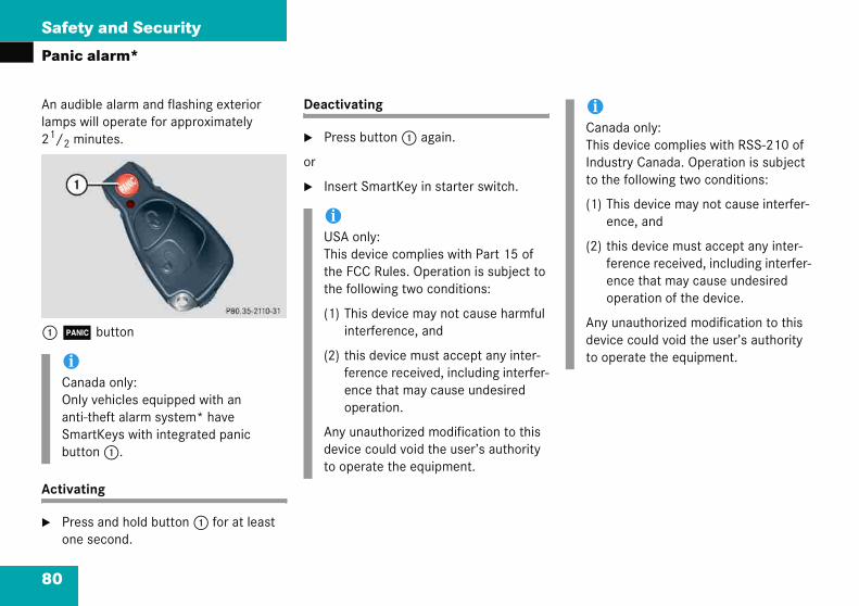
Safety and Security
ibwi
ti
s
alyi-ato
iCanada only: This device complies with RSS-210 of Industry Canada. Operation is subject to the following two conditions:
(1) This device may not cause interfer-ence, and
(2) this device must accept any inter-ference received, including interfer-ence that may cause undesired operation of the device.
Any unauthorized modification to this device could void the user’s authority to operate the equipment.
80
Panic
An audlamps 21/2 m
1 Â
Activa
� Preone
iCanOnantSmbut
alarm*
le alarm and flashing exterior ill operate for approximately nutes.
button
ng
s and hold button 1 for at least second.
Deactivating
� Press button 1 again.
or
� Insert SmartKey in starter switch.
da only: vehicles equipped with an theft alarm system* have rtKeys with integrated panic n 1.
iUSA only:This device complies with Part 15 of the FCC Rules. Operation is subject to the following two conditions:
(1) This device may not cause harmful interference, and
(2) this device must accept any inter-ference received, including interfer-ence that may cause undesired operation.
Any unauthorized modification to this device could void the user’s authority to operate the equipment.
81
Safety and Security
Driving safety systems
�In the
�
�
�
On slippery road surfaces, the ABS will re-spond even to light brake pressure.
The - indicator lamp in the instrument cluster (� page 24) comes on when you switch on the ignition. It goes out when the engine is running.
Braking
At the instant one of the wheels is about to lock up, a slight pulsation can be felt in the brake pedal, indicating that the ABS is in the regulating mode.
� Keep firm and steady pressure on the brake pedal while experiencing the pul-sation.
Continuous, steady brake pedal pressure yields the advantages provided by the ABS, namely braking power and the ability to steer the vehicle.
The pulsating brake pedal can be an indica-tion of hazardous road conditions and functions as a reminder to take extra care while driving.
W
Tc
�
�
�
Tr
Av
Drivinthis sec follow
ABS (A
BAS (B
ESP (E
arning
he followidents:
Exces
Wet a
Follo
he ABS,isk.
lways aailing ro
g safety systemstion you will find information on ing driving safety systems:
ntilock Brake System)
rake Assist System)
lectronic Stability Program)
ABS
The Antilock Brake System (ABS) regulates the brake pressure so that the wheels do not lock during braking. This allows you to maintain the ability to steer your vehicle.
The ABS is functional above a speed of ap-proximately 5 mph (8 km/h) independent of road surface conditions.
! G
ing factors increase the risk of ac-
sive speed, especially in turns
nd slippery road surfaces
wing another vehicle too closely
BAS and ESP cannot reduce this
djust your driving style to the pre-ad and weather conditions.
iIn winter operation, the maximum ef-fectiveness of the ABS and ESP is only achieved with winter tires (M+S tires), or snow chains as required.
Warning! G
Do not pump the brake pedal. Use firm, steady brake pedal pressure instead. Pump-ing the brake pedal defeats the purpose of the ABS and significantly reduces braking effectiveness.

82
Safety and Security
Drivin
Emerge
� Keepbrak
For more(� page
or more information, see “Practical hints” page 354).
Warni
The ABSphysicsit increayond thvehicleABS cathose rturns, for hydrskillful pabilitienever bous maer’s saf
Warning! G
The BAS cannot prevent the natural laws of physics from acting on the vehicle, nor can it increase braking efficiency beyond that af-forded by the condition of the vehicle brakes and tires or the traction afforded. The BAS cannot prevent accidents, including those resulting from excessive speed in turns, fol-lowing another vehicle too closely, or hydro-planing. Only a safe, attentive, and skillful driver can prevent accidents. The capabili-ties of a BAS equipped vehicle must never be exploited in a reckless or dangerous manner which could jeopardize the user’s safety or the safety of others.
g safety systems
ncy brake maneuver
continuous full pressure on the e pedal.
information, see “Practical hints” 340).
BAS
The Brake Assist System (BAS) operates in emergency situations. If you apply the brakes very quickly, the BAS automatically provides full brake boost, thereby poten-tially reducing the braking distance. Apply continuous full braking pressure until the emergency braking situation is over. The ABS will prevent the wheels from locking.
When you release the brake pedal, the brakes function again as normal. The BAS is then deactivated.
F(�
ng! G
cannot prevent the natural laws of from acting on the vehicle, nor can se braking or steering efficiency be-at afforded by the condition of the brakes and tires or the traction. The nnot prevent accidents, including esulting from excessive speed in ollowing another vehicle too closely, oplaning. Only a safe, attentive, and driver can prevent accidents. The ca-s of an ABS equipped vehicle must e exploited in a reckless or danger-nner which could jeopardize the us-ety or the safety of others.
Warning! G
If the BAS malfunctioning, the brake system is still functioning normally, but without the additional brake boost available that BAS would normally provide in an emergency braking maneuver. Therefore, the braking distance may increase.

83
Safety and Security
Driving safety systems
ESP
The Eleoperatning an(force tires an
The ESspinninapplyinand byworks especiwet or stabilizmaneu
The ESspeedoengage
The ESspeedoon the is runn
Warning! G
The ESP cannot prevent the natural laws of physics from acting on the vehicle, nor can it increase the traction afforded. The ESP cannot prevent accidents, including those resulting from excessive speed in turns, or hydroplaning. Only a safe, attentive, and skillful driver can prevent accidents. The ca-pabilities of an ESP equipped vehicle must never be exploited in a reckless or danger-ous manner which could jeopardize the us-er’s safety or the safety of others.
!The ESP will only function properly if you use wheels of the recommended tire size (� page 419).
ctronic Stability Program (ESP) is ional as soon as the engine is run-d monitors the vehicle’s traction
of adhesive friction between the d the road surface) and handling.
P recognizes when a wheel is g or if the vehicle starts to skid. By g brakes to the appropriate wheel limiting engine output, the ESP to stabilize the vehicle. The ESP is ally useful while driving off and on slippery road surfaces. The ESP also es the vehicle during braking vers.
P warning lamp v in the meter flashes when the ESP is d.
P warning lamp v in the meter comes on when you switch
ignition. It goes out when the engine ing.
Warning! G
Never switch off the ESP when you see the ESP warning lamp v flashing in the speedometer dial. In this case proceed as follows:
� While driving off, apply as little throttle as possible.
� While driving, ease up on the accelera-tor.
� Adapt your speed and driving style to the prevailing road conditions.
Failure to observe these guidelines could cause the vehicle to skid.
The ESP cannot prevent accidents resulting from excessive speed.

84
Safety and Security
Drivin
For more(� page
hen you switch off the ESP
the ESP does not stabilize the vehicle
the engine output is not limited, which allows the drive wheels to spin and thus cut into surfaces for better grip
the traction control will still brake a spinning wheel
the ESP continues to operate when you are braking
!Becation,(Smaor 1)
� ta
� tfr
Activmay rear
The Eyou utire s
iWhen the ESP is switched off and one or more drive wheels are spinning, the ESP warning lamp v in the speed-ometer flashes. However, the ESP will then not stabilize the vehicle.
g safety systems
information, see “Practical hints” 343).
Switching off the ESP
To improve the vehicle’s traction, turn off the ESP in driving situations where it would be advantageous to have drive wheels spin and thus cut into surfaces for better grip such as:
� starting out on slippery surfaces and in deep snow in conjunction with snow chains
� sand or gravel
W
�
�
�
�
use of the ESP’s automatic opera- the engine must be shut off rtKey in starter switch position 0 when
he parking brake is being tested on brake test dynamometer
he vehicle is being towed with the ont axle raised
e braking action through the ESP otherwise seriously damage the axle brake system.
SP will only function properly if se wheels of the recommended ize.
Warning! G
The ESP should not be switched off during normal driving other than in the circum-stances described below. Disabling of the system will reduce vehicle stability in stan-dard driving maneuvers.
!Turn on the ESP immediately if the aforementioned circumstances do not apply anymore.

85
Safety and Security
Driving safety systems
The swconsol
1 ESP
� Pre
Thespe
The
Switching on the ESP
� Press switch 1 again
The ESP warning lamp v in the speedometer goes out.
You are now again in normal driving mode with the ESP switched on.
itch is located on the center e.
switch (off/on)
ss ESP switch 1.
ESP warning lamp v in the edometer comes on.
ESP is deactivated.
Warning! G
When the ESP warning lamp v is illuminated continuously, the ESP is switched off.
Adapt your speed and driving to the prevail-ing road conditions and to the non-operating status of the ESP.
!Avoid spinning of a drive wheel for an extended period with the ESP switched off. This may cause serious damage to the drivetrain which is not covered by the Mercedes-Benz Limited Warranty.
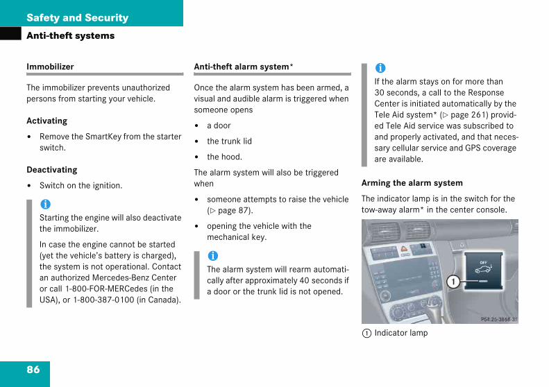
Safety and Security
h
i
ms
ti
tc
v
it rming the alarm system
he indicator lamp is in the switch for the w-away alarm* in the center console.
Indicator lamp
rt i
at saua
A
iIf the alarm stays on for more than 30 seconds, a call to the Response Center is initiated automatically by the Tele Aid system* (� page 261) provid-ed Tele Aid service was subscribed to and properly activated, and that neces-sary cellular service and GPS coverage are available.
86
Anti-t
Immob
The imperson
Activa
� Remswi
Deacti
� Sw
iStathe
In c(yethean or cUS
eft systems
lizer
obilizer prevents unauthorized from starting your vehicle.
ng
ove the SmartKey from the starter h.
ating
ch on the ignition.
Anti-theft alarm system*
Once the alarm system has been armed, a visual and audible alarm is triggered when someone opens
� a door
� the trunk lid
� the hood.
The alarm system will also be triggered when
� someone attempts to raise the vehicle (� page 87).
� opening the vehicle with the mechanical key.
A
Tto
1
ing the engine will also deactivate mmobilizer.
se the engine cannot be started the vehicle’s battery is charged), ystem is not operational. Contact thorized Mercedes-Benz Center ll 1-800-FOR-MERCedes (in the
), or 1-800-387-0100 (in Canada).
iThe alarm system will rearm automati-cally after approximately 40 seconds if a door or the trunk lid is not opened.

87
Safety and Security
Anti-theft systems
� Loc
Theto iactflasafte
Tow-away alarm*
Once the tow-away alarm is armed, a visual and audible alarm will be triggered when someone attempts to raise the vehicle.
iIf ththreme
�
�
�
Clothe
iThe tow away protection alarm is triggered, for example, if the vehicle is lifted on one side.
If the alarm stays on for more than 30 seconds, a call to the Response Center is initiated automatically by the Tele Aid system* (� page 261) provid-ed Tele Aid service was subscribed to and properly activated, and that neces-sary cellular service and GPS coverage are available.
k the vehicle with the SmartKey.
turn signal lamps flash three times ndicate that the alarm system is ivated. Indicator lamp 1 begins to h after approximately 30 seconds r arming the alarm system.
Disarming the alarm system
� Unlock the vehicle with the SmartKey.
The turn signal lamps flash once to indicate that the alarm system is deac-tivated.
Canceling the alarm
To cancel the alarm:
� Press the Œ or ‹ button on the SmartKey.
or
� Insert the SmartKey in the starter switch.
e turn signal lamps do not flash e times one of the following ele-
nts may not be properly closed:
a door
the trunk lid
the hood
se the respective element and lock vehicle again.
iThe alarm system will rearm automati-cally after approximately 40 seconds if a door or the trunk lid is not opened.

88
Safety and Security
Anti-th
Arming
� Lock
The tarme
Switch off the ignition.
Press switch 1.
Indicator lamp 2 in switch comes on briefly.
Exit and lock your vehicle with the SmartKey.
he tow-away alarm remains disarmed ntil you lock your vehicle again.
anceling the alarm
o cancel the alarm:
Press the Œ or ‹ button on the SmartKey.
r
Insert the SmartKey in the starter switch.
iWhetow-autoremavehic
iYou cannot disarm the tow-away alarm while the ignition is switched on.
eft systems
tow-away alarm
the vehicle with the SmartKey.
ow-away alarm is automatically d after about 30 seconds.
Disarming tow-away alarm
To prevent triggering the tow-away alarm , switch off the tow-away alarm feature before towing the vehicle, or when parking on a surface subject to movement, such as a ferry or auto train.
The switch is located on the center con-sole.
1 Tow-away alarm off switch2 Indicator lamp
�
�
�
Tu
C
T
�
o
�
n you unlock your vehicle, the away protection disarms matically. The tow away alarm ins disarmed until you lock the le again.

89
Controls in detail
Locking and unlocking
Seats
Memory function*
Lighting
Instrument cluster
Control system
Manual transmission
Automatic transmission*
Good visibility
Climate control
Automatic climate control*
Audio system
Power windows
roof with power tilt/sliding panel*
Driving systems
Loading
Useful features
Panorama

Controls in detail
“Cta eo
un o
kctgrrhe
in
martKey with remote controls
‹ Lock buttonMechanical key locking tabŒ Unlock buttonBattery check lamp Panic button* (� page 80)
iCanada only:Only vehicles equipped with an anti-theft alarm system* have SmartKeys with integrated panic button 5.
90
In the find deate thecle. If ybasic fwill be
To quicsic fun“GettinThe coen at t
Lock
ontrols in detail” section you will iled information on how to oper-quipment installed on your vehi-u are already familiar with the ctions of your vehicle, this section f particular interest to you.
ly familiarize yourself with the ba-ions of the vehicle, refer to the started” section of this manual. esponding page numbers are giv- beginning of each segment.
g and unlocking
For more information on locking and unlocking, “Getting started” (� page 32) and (� page 56).
SmartKey
Your vehicle comes supplied with two SmartKeys, each with remote control and a removable mechanical key. The locking tabs for the mechanical key portion of the two keys are a different color to help dis-tinguish each key unit.
The SmartKey provides an extended oper-ating range. To prevent theft, however, it is advisable to only unlock the vehicle when you are in close proximity to it.
The SmartKey centrally locks and unlocks:
� the doors
� the trunk lid
� the fuel filler flap
S
12345

91
Controls in detail
Locking and unlocking
Warn
WhenSmartwith ychildraccesfor chinsideand/o
!To expele
iCanada only: This device complies with RSS-210 of Industry Canada. Operation is subject to the following two conditions:
(1) This device may not cause interfer-ence, and
(2) this device must accept any inter-ference received, including interfer-ence that may cause undesired operation of the device.
Any unauthorized modification to this device could void the user’s authority to operate the equipment.
iYou can also open and close the power windows (� page 239) and panorama roof with power tilt/sliding panel* (� page 244) using the SmartKey.
ing! G
leaving the vehicle, always remove the Key from the starter switch, take it ou, and lock the vehicle. Do not leave en unattended in the vehicle, or with s to an unlocked vehicle. It is possible ildren to open a locked door from the , which could result in an accident r serious injury.
prevent possible malfunction, avoid osing the SmartKey to high levels of ctromagnetic radiation.
iUSA only:This device complies with Part 15 of the FCC Rules. Operation is subject to the following two conditions:
(1) This device may not cause harmful interference, and
(2) this device must accept any inter-ference received, including interfer-ence that may cause undesired operation.
Any unauthorized modification to this device could void the user’s authority to operate the equipment.

92
Controls in detail
Lockin
Factory
Global u
� Pres
All tulockiThe adisar
The vehiand reactem* wiunlockin
� neith
� the Sstart
� the cactiv
nlocking driver’s door and fuel filler ap
Press button Πonce.
All turn signal lamps flash once. The locking knob in the driver’s door moves up. The anti-theft alarm system* disarmed.
lobal unlocking
Press button Πtwice.
All turn signal lamps flash once. The locking knobs in the doors move up. The anti-theft alarm system* is disarmed.
g and unlocking
setting
nlocking
s button Œ.
rn signal lamps flash once. The ng knobs in the doors move up. nti-theft alarm system* is med.
cle will lock again automatically tivate the anti-theft alarm sys-
thin approximately 40 seconds of g if:
er door nor trunk lid is opened
martKey is not inserted in the er switch
entral locking switch is not ated
Global locking
� Press button ‹.
With the hood, trunk and all doors closed, all turn signal lamps flash three times. The locking knobs in the doors move down. The anti-theft alarm sys-tem* is armed.
Selective setting
If you frequently travel alone, you may wish to reprogram the SmartKey so that pressing Œ only unlocks the driver’s door and the fuel filler flap.
� Press and hold buttons Œ and ‹ simultaneously for about five seconds until battery check lamp 4 flashes twice.
The SmartKey will then function as follows:
Ufl
�
G
�

93
Controls in detail
Locking and unlocking
Global
� Pre
Witclotimmotem
Restor
� Presimunttwi
Checking the batteries
� Press button ‹ or Œ.
Battery check lamp 4 comes on brief-ly to indicate that the SmartKey batter-ies are in order.
iIf battery check lamp 4 does not come on briefly during check, then the SmartKey batteries are discharged.
Replace the batteries (� page 383).
You can obtain the required batteries at any authorized Mercedes-Benz Center.
iIf the batteries are checked within sig-nal range of the vehicle, pressing the ‹ or Œ button will lock or unlock the vehicle accordingly.
locking
ss button ‹.
h the hood, trunk and all doors sed, all turn signal lamps flash three es. The locking knobs in the doors ve down. The anti-theft alarm sys-* is armed.
ing to factory setting
ss and hold buttons Œ and ‹ ultaneously for about six seconds il battery check lamp 4 flashes ce.
!If you can no longer lock or unlock the vehicle with the SmartKey, then either the batteries in the SmartKey are dis-charged, the SmartKey is malfunction-ing or the vehicle battery is drained.
� Check the batteries in the SmartKey and replace them if necessary (� page 383).
� Use the mechanical key to unlock the driver’s door (� page 377).
� Use the mechanical key to lock the driver’s door (� page 379).
� Have the vehicle battery and the battery connections checked (� page 401).
If the SmartKey is malfunctioning, contact an authorized Mercedes-Benz Center.
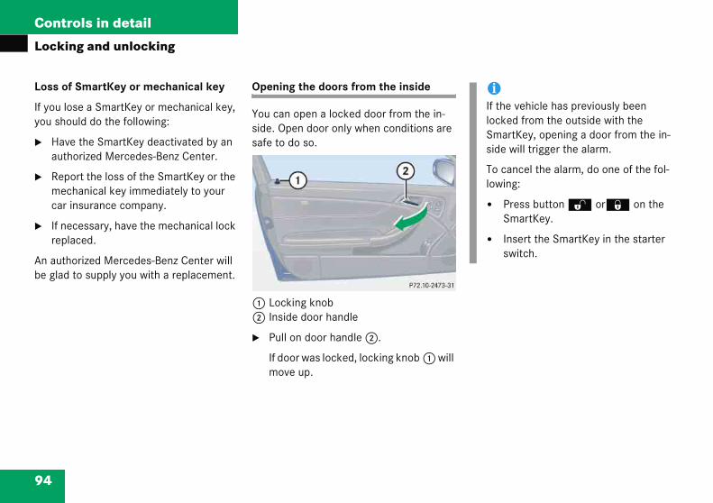
94
Controls in detail
Lockin
Loss of
If you loyou sho
� Haveauth
� Repomeccar i
� If nerepla
An authobe glad
iIf the vehicle has previously been locked from the outside with the SmartKey, opening a door from the in-side will trigger the alarm.
To cancel the alarm, do one of the fol-lowing:
� Press button Œ or‹ on the SmartKey.
� Insert the SmartKey in the starter switch.
g and unlocking
SmartKey or mechanical key
se a SmartKey or mechanical key, uld do the following:
the SmartKey deactivated by an orized Mercedes-Benz Center.
rt the loss of the SmartKey or the hanical key immediately to your nsurance company.
cessary, have the mechanical lock ced.
rized Mercedes-Benz Center will to supply you with a replacement.
Opening the doors from the inside
You can open a locked door from the in-side. Open door only when conditions are safe to do so.
1 Locking knob2 Inside door handle
� Pull on door handle 2.
If door was locked, locking knob 1 will move up.

95
Controls in detail
Locking and unlocking
Openin
A minim(2.16 m
The hacense
1 Han
Closing the trunk lid
1 Handle
� Lower trunk lid by pulling firmly on grip 1.
� Close trunk lid with hands placed flat on the trunk lid.
g the trunk lid
um height clearance of 7.1 ft. ) is required to open the trunk lid.
ndle is located above the rear li-plate recess.
dle
The vehicle must be unlocked.
� Pull on handle 1.
The trunk lid unlocks.
� Lift the trunk lid.
The trunk can also be opened from its in-side in an emergency, see “Trunk lid emer-gency release” (� page 96).
!Always make sure there is sufficient overhead clearance.

96
Controls in detail
Lockin
runk lid emergency release
he emergency release button is located n the inside of the trunk lid.
Emergency release button
Briefly press emergency release button 1.
The trunk lid unlocks.
Lift the trunk lid.
Warni
To prevkeep haopeningcially caaround
When leSmartKwith yochildrenaccess vised uan acci
!Always make sure there is sufficient overhead clearance.
g and unlocking
T
To
1
�
�
ng! G
ent possible personal injury, always nds and fingers away from the trunk when closing the trunk. Be espe-reful when small children are
.
aving the vehicle, always remove the ey from the starter switch, take it u, and lock the vehicle. Do not leave unattended in the vehicle, or with to an unlocked vehicle. Unsuper-se of vehicle equipment may cause dent and/or serious personal injury.
Warning! G
Only drive with the trunk closed as, among other dangers such as visibility blockage, exhaust fumes may enter the vehicle interior.
iDo not place the SmartKey in the open trunk. You may lock yourself out.
iIf the vehicle was previously centrally locked, the trunk lid will lock automati-cally after closing it. The turn signals flash three times to confirm locking.

97
Controls in detail
Locking and unlocking
Illuminbutton
� Theafte
� Theafte
Automatic central locking
The doors and the trunk lid automatically lock when the ignition is switched on and the wheels are turning at vehicle speeds of approximately 9 mph (15 km/h) or more.
You can open a locked door from the in-side. Open door only when conditions are safe to do so.
You can deactivate the automatic locking mode using the control system (� page 148).
iTheandsta
iThenottery
iThe doors unlock automatically after an accident if the force of the impact exceeds a preset threshold.
To prevent the vehicle door locks from locking, deactivate the automatic cen-tral locking when the vehicle
� is pushed or towed
� is on a test stand
ation of the emergency release :
button will flash for 30 minutes r opening the trunk.
button will flash for 60 minutes r closing the trunk.
emergency release button unlocks opens the trunk while the vehicle is
nding still or in motion.
emergency release button does open the trunk lid if the vehicle bat- is discharged or disconnected.
iIf the emergency release button is pressed and the vehicle was centrally locked from the outside using the SmartKey, the exterior lamps will flash and the alarm will sound as the trunk lid opens. To cancel the alarm, do one of the following:
� Press button Œ or ‹ on the SmartKey.
� Insert the SmartKey in the starter switch.

98
Controls in detail
Lockin
Locking
You cantrunk liding switcif you waing to dr
You cannwith the
witch design B
Central locking switchCentral unlocking switch
Warni
When leSmartKwith yochildrenaccess vised uan acci
g and unlocking
and unlocking from the inside
lock or unlock the doors and the from inside using the central lock-h. This can be useful, for example, nt to lock the vehicle before start-ive.
ot lock or unlock the fuel filler flap central locking switch.
Depending on production date, your vehicle is equipped with either switch de-sign A or B.
The switches are located in the center console.
Switch design A
1 Central locking switch2 Central unlocking switch
S
12
ng! G
aving the vehicle, always remove the ey from the starter switch, take it u, and lock the vehicle. Do not leave unattended in the vehicle, or with to an unlocked vehicle. Unsuper-se of vehicle equipment may cause dent and/or serious personal injury.

99
Controls in detail
Locking and unlocking
iYouinsare
If thlocunlswi
If thwit
�
�
Locking
� Press central locking switch 1.
If all doors are closed, the vehicle locks.
Unlocking
� Press central unlocking switch 2.
The vehicle unlocks.
can open a locked door from the ide. Open door only when conditions safe to do so.
e vehicle was previously centrally ked using the SmartKey, it will not ock using the central unlocking tch 2.
e vehicle was previously locked h the central locking switch 1
while in the selective remote con-trol mode, only the door opened from the inside is unlocked.
while in the global remote control mode, the vehicle is unlocked completely when a door is opened from the inside.

Controls in detail
or”
n
atm
syei
hen exiting the vehicle, with the asy-entry/exit feature activated and epending on your selection, the steering heel tilts upwards and/or the driver’s eat moves a few inches to the rear when ou:
remove the SmartKey from the starter switch,
or
open the driver’s door with the SmartKey in starter switch position 0 or 1.
100
Seats
For inf“Seats
Easy-e
This feexit fro
The eaactivatConvensystem
mation on seat adjustment, see (� page 35).
try/exit feature*
ure allows for easier entry into and the vehicle.
-entry/exit feature can be d or deactivated in the ence submenu of the control (� page 148).
Wedwsy
�
�
Warning! G
You must make sure no one can become trapped or injured by the moving steering wheel and driver’s seat when the easy-en-try/exit feature is activated.
To cancel seat/steering wheel movement, do one of the following:
� Press seat adjustment switch* (� page 38).
� Move steering column stalk* (� page 41).
� Press the memory position switch* (� page 108).
Do not leave children unattended in the ve-hicle, or with access to an unlocked vehicle. Children could open the driver’s door and unintentionally activate the easy-entry/exit feature, which could result in an accident and/or serious personal injury.

101
Controls in detail
Seats
iIf thwhetheableas
If thfactemtionentmoexit
iFor safety reasons, the driver’s seat will not return to its last set position with the easy-entry/exit feature activated if the system recognizes the last set posi-tion as an extreme forward position. In-stead, the driver’s seat will remain at or move to a factory-set maximum for-ward position. To again fully return the driver’s seat to your last set position or to memory position, adjust the seat to the desired position or press and hold the respective memory position but-ton* (� page 108).
When entering the vehicle, with the easy-entry/exit feature activated, the steering wheel or, depending on your selection, the steering wheel and driver’s seat will return to their last set position or a factory-set maximum forward position when you:
� close the driver’s door with the ignition switched on
� insert the SmartKey into the starter switch with the driver’s door closed.
e current position for the steering el is in the uppermost tilt position,
steering wheel will no longer be e to move upward when the y-entry/exit feature is activated.
e current seat position falls into a tory-set position range and the sys- recognizes the current seat posi- to be rearward enough for easy ry and exit, the driver’s seat will not ve to the rear when the easy-entry/ feature is activated.
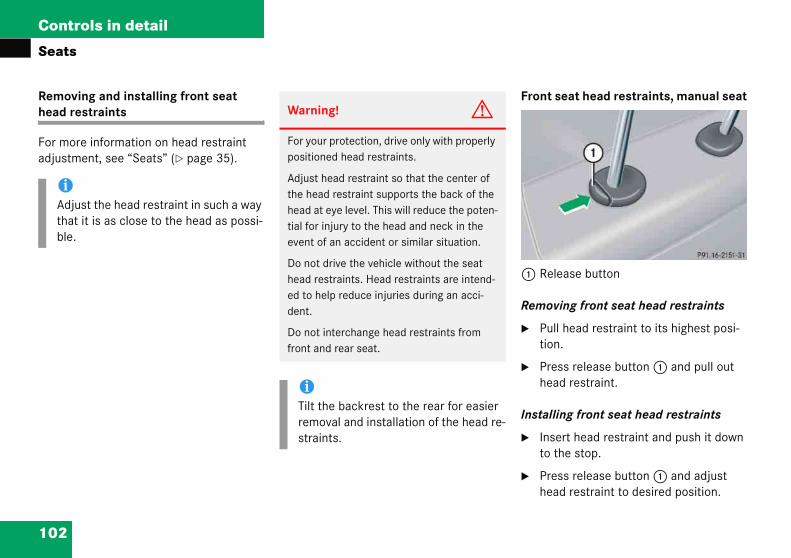
102
Controls in detail
Seats
Removihead re
For moradjustm
ront seat head restraints, manual seat
Release button
emoving front seat head restraints
Pull head restraint to its highest posi-tion.
Press release button 1 and pull out head restraint.
stalling front seat head restraints
Insert head restraint and push it down to the stop.
Press release button 1 and adjust head restraint to desired position.
iAdjuthat ble.
ng and installing front seat straints
e information on head restraint ent, see “Seats” (� page 35).
F
1
R
�
�
In
�
�
st the head restraint in such a way it is as close to the head as possi-
Warning! G
For your protection, drive only with properly positioned head restraints.
Adjust head restraint so that the center of the head restraint supports the back of the head at eye level. This will reduce the poten-tial for injury to the head and neck in the event of an accident or similar situation.
Do not drive the vehicle without the seat head restraints. Head restraints are intend-ed to help reduce injuries during an acci-dent.
Do not interchange head restraints from front and rear seat.
iTilt the backrest to the rear for easier removal and installation of the head re-straints.

103
Controls in detail
Seats
Front
The hein each
1 Hea
� Sw
Rear seat head restraints
Head restraint height
1 Release button
Warning! G
For safety reasons, always drive with the rear head restraints in the upright position when the rear seats are occupied.
Keep the area around head restraints clear of articles (e.g. clothing) to not obstruct the folding operation of the head restraints.
seat head restraints, power seat*
ad restraint height switch is located door.
d restraint switch
itch on the ignition (� page 33).
Removing front seat head restraints
� Press switch 1 upwards and hold until the head restraint is fully extended.
� Pull out head restraint.
Installing front seat head restraints
� Press switch 1 upwards and hold for about five seconds.
� Push the head restraint down until it engages.
� Adjust head restraint to desired posi-tion.
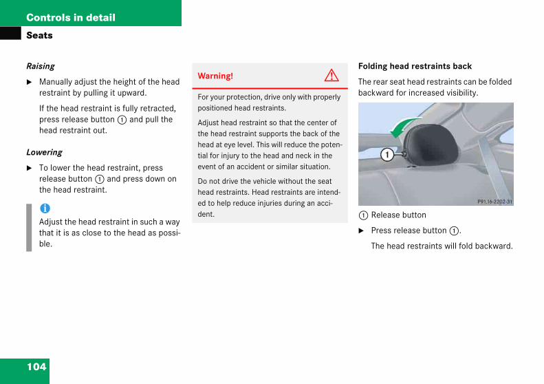
104
Controls in detail
Seats
Raising
� Manrestr
If thepreshead
Lowerin
� To loreleathe h
olding head restraints back
he rear seat head restraints can be folded ackward for increased visibility.
Release button
Press release button 1.
The head restraints will fold backward.
iAdjuthat ble.
ually adjust the height of the head aint by pulling it upward.
head restraint is fully retracted, s release button 1 and pull the restraint out.
g
wer the head restraint, press se button 1 and press down on ead restraint.
F
Tb
1
�st the head restraint in such a way it is as close to the head as possi-
Warning! G
For your protection, drive only with properly positioned head restraints.
Adjust head restraint so that the center of the head restraint supports the back of the head at eye level. This will reduce the poten-tial for injury to the head and neck in the event of an accident or similar situation.
Do not drive the vehicle without the seat head restraints. Head restraints are intend-ed to help reduce injuries during an acci-dent.

105
Controls in detail
Seats
Placin
� Pulloc
Head r
Two ditions a
� Prehea
1 Release button
Removing rear seat head restraints
� Fold back head restraint (� page 104).
� Pull head restraint to its highest posi-tion.
� Press release button 1 and pull out head restraint.
Installing rear seat head restraints
� Insert head restraint and push it down until it engages.
� Press release button 1 and adjust head restraint to desired position.
Warn
Makeplacintectiv
g head restraints upright
l the head restraint forward until it ks into position.
estraint tilt
fferent head restraint angle posi-re available.
ss the release button and tilt the d restraint to the desired position.
Removing and installing rear seat head restraints
ing! G
sure the head restraints engage when g them upright. Otherwise their pro-e function cannot be assured.
iAdjust the head restraint in such a way that it is as close to the head as possi-ble.
Warning! G
For your protection, drive only with properly positioned head restraints.
Adjust head restraint so that the center of the head restraint supports the back of the head at eye level. This will reduce the poten-tial for injury to the head and neck in the event of an accident or similar situation.
Do not drive the vehicle without the seat head restraints. Head restraints are intend-ed to help reduce injuries during an acci-dent.
Do not interchange head restraints from front and rear seat.

106
Controls in detail
Seats
Seat he
The swited in the
1 Seat2 Indic
witching on seat heating
Press switch 1 twice.
Three red indicator lamps 2 in the switch come on.
Continue pressing switch 1 until desired seat heating level is reached.
witching off seat heating
Press switch 1 repeatedly until all indicator lamps 2 go out.
iIf one or all of the indicator lamps 2 on the seat heating switch are flashing, there is insufficient voltage due to too many electrical consumers are turned on. The seat heating switches off automatically.
The seat heating will switch back on again automatically as soon as sufficient voltage is available.
ating*
ches for the front seats are locat- center console.
heating switchator lamps
The red indicator lamps 2 on the switch show the heating level selected:
� Switch on the ignition (� page 33).
S
�
�
S
�
Level
3 Three indicator lamps on.
After approximately 5 minutes, seat heating is automatically switched to level 2.
2 Two indicator lamps on.
After approximately 10 minutes, seat heating is automatically switched to level 1.
1 One indicator lamp on.
After approximately 20 minutes, seat heating is automatically switched off.
off No indicator lamp on.

107
Controls in detail
Memory function*
�The following settings are not key-dependent. They are stored when using the buttons on the passenger door:
� Front passenger seat, backrest and head restraint position.
Warning! G
Do not activate the memory function while driving. Activating the memory function while driving could cause the driver to lose control of the vehicle.
Mem
!Prior ter shoheightseat bsure afort. Tadjustsectioproper
In addensuretion anexteriojusted
Fastenchildresecurewith UStandaMotorand 21
ory function*You can store up to three different settings per SmartKey.
The following settings are saved for each stored position:
� Driver’s seat, backrest and head restraint position
� Steering wheel position
� Exterior rear view mirror positions
These key-dependent memory settings can be deactivated if desired. For informa-tion on key-dependent memory settings, see “Setting key-dependency” (� page 149).
o operating the vehicle, the driv-uld check and adjust the seat , seat position fore and aft, and ackrest angle if necessary, to en-dequate control, reach and com-he head restraint should also be ed for proper height. See also the n on air bags (� page 61) for seat positioning.
ition, adjust the steering wheel to adequate control, reach, opera-d comfort. Both the interior and r rear view mirrors should be ad-
for adequate rear vision.
seat belts. Infants and small n should be seated in a properly d restraint system that complies .S. Federal Motor Vehicle Safety rds 213 and 225 and Canadian
Vehicle Safety Standards 213 0.2.

108
Controls in detail
Memo
The memswitch a
1 Mem2 Mem
� Swit
or
� Openthe S
ecalling positions from memory
Turn memory position switch 2 to selected memory position.
Press and hold memory position switch 2 until the seat, steering wheel and exterior rear view mirrors have completely moved to the stored positions.
!Do not operate the power seats using the memory button if the seat backrest is in an excessively reclined position. Doing so could cause damage to front or rear seats.
iReleasing the memory position switch stops movement to the stored posi-tions immediately.
ry function*
ory button and memory position re located on the door.
ory buttonory position switch
ch on the ignition (� page 33).
the respective door and insert martKey in the starter switch.
Storing positions into memory
� Adjust the seats, steering wheel and exterior rear view mirrors to the desired position (� page 35).
� Turn memory position switch 2 to selected memory position.
� Press memory button 1.
� Release memory button 1 and press memory position switch 2 within three seconds.
All settings are stored at the selected position.
R
�
�
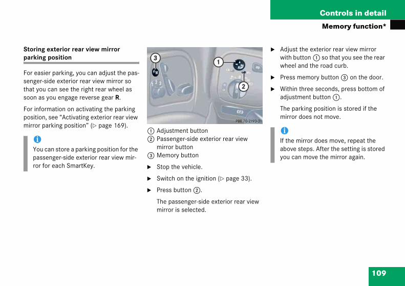
109
Controls in detail
Memory function*
Storinparkin
For eassengerthat yosoon a
For infpositiomirror
� Adjust the exterior rear view mirror with button 1 so that you see the rear wheel and the road curb.
� Press memory button 3 on the door.
� Within three seconds, press bottom of adjustment button 1.
The parking position is stored if the mirror does not move.
iYoupasror
iIf the mirror does move, repeat the above steps. After the setting is stored you can move the mirror again.
g exterior rear view mirror g position
ier parking, you can adjust the pas--side exterior rear view mirror so u can see the right rear wheel as s you engage reverse gear R.
ormation on activating the parking n, see “Activating exterior rear view parking position” (� page 169).
1 Adjustment button2 Passenger-side exterior rear view
mirror button3 Memory button
� Stop the vehicle.
� Switch on the ignition (� page 33).
� Press button 2.
The passenger-side exterior rear view mirror is selected.
can store a parking position for the senger-side exterior rear view mir-for each SmartKey.
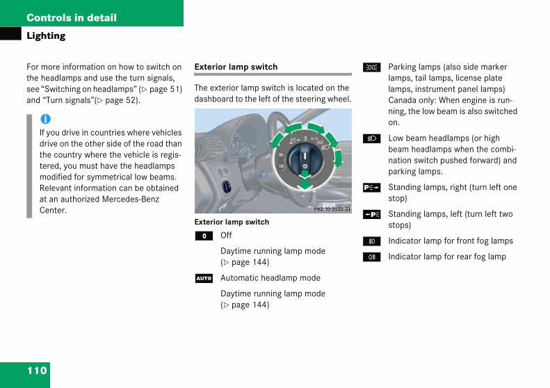
Controls in detail
in
rad
ur
Parking lamps (also side marker lamps, tail lamps, license plate lamps, instrument panel lamps)Canada only: When engine is run-ning, the low beam is also switched on.
Low beam headlamps (or high beam headlamps when the combi-nation switch pushed forward) and parking lamps.
Standing lamps, right (turn left one stop)
Standing lamps, left (turn left two stops)
Indicator lamp for front fog lamps
Indicator lamp for rear fog lamp
oue ceddent
110
Light
For mothe hesee “Swand “T
iIf ydrivthetermoRelat aCen
g
e information on how to switch on lamps and use the turn signals,
itching on headlamps” (� page 51) n signals”(� page 52).
Exterior lamp switch
The exterior lamp switch is located on the dashboard to the left of the steering wheel.
Exterior lamp switch
M Off
Daytime running lamp mode (� page 144)
U Automatic headlamp mode
Daytime running lamp mode (� page 144)
C
B
ˆ
‚
‡
†
drive in countries where vehicles on the other side of the road than ountry where the vehicle is regis-, you must have the headlamps
ified for symmetrical low beams. vant information can be obtained authorized Mercedes-Benz er.

111
Controls in detail
Lighting
Manua
The lowlamps exterio
� Turn exterior lamp switch to position U.
With the SmartKey in starter switch position 1, only the parking lamps will switch on and off automatically.
When the engine is running, the low beam headlamps, the tail and parking lamps, the license plate lamps and the side marker lamps will switch on and off automatically.
iWitstaopebea
�
�
�
In low ambient lighting conditions, only switch from position U to B with the vehicle at a standstill. Switching from U to B will briefly switch off the head-lamps. Doing so while driving in low ambient lighting conditions may result in an acci-dent.
The automatic headlamp feature is only an aid to the driver. The driver is responsible for the operation of the vehicle's lights at all times.
l headlamp mode
beam headlamps and parking can be switched on and off with the r lamp switch.
Automatic headlamp mode
The following lamps switch on and off automatically depending on the brightness of the ambient light:
� Low beam headlamps
� Tail and parking lamps
� License plate lamps
� Side marker lamps
h the SmartKey removed from the rter switch and the driver’s door n, while the parking lamps or low m headlamps are switched on,
a warning sounds
$ appears in the multifunction display
the message Switch off lights. appears in the multifunction display
Warning! G
If the exterior lamp switch is set to U,
� the headlamps may switch off unexpect-edly when the system senses bright am-bient light, for example light from oncoming traffic.
� the headlamps will not be automatically switched on under foggy conditions.
To minimize risk to you and to others, acti-vate headlamps by turning exterior lamp switch to B when driving or when traffic and/or ambient lighting conditions require you to do so.
112
Controls in detail
Lightin
Daytime
� Turnposit
Whebeam
In lowlowinly.
� T
� L
� S
For nighexterior permit alamps.
SA only
y default, the daytime running lamp mode deactivated. Activate the daytime run-ing lamp mode using the control system, ee “Setting daytime running lamp mode SA only)” (� page 144).
hen the engine is running, and you turn e exterior lamp switch to position C
r B, the manual headlamp mode has riority over the daytime running lamp ode.
he corresponding exterior lamps switch n (� page 110).
ocator lighting and night security lumination
he locator lighting and night security illu-ination are described in the control sys-m section, see “Setting locator lighting” page 145) and “Headlamps delayed
hut off” (� page 146).
iWithactivin polamp
g
running lamp mode
exterior lamp switch to ion M or U.
n the engine is running, the low headlamps are switched on.
ambient light conditions, the fol-g lamps will switch on additional-
ail and parking lamps
icense plate lamps
ide marker lamps
ttime driving you should turn the lamp switch to position B to ctivation of the high beam head-
Canada only
The daytime running lamp mode is manda-tory and therefore in a constant mode.
Vehicles with automatic transmission*: When the engine is running, and you shift from a driving position to position N or P, the low beam headlamps will switch off with a three-minute time delay.
When the engine is running, and you
� turn the exterior lamp switch to position C, the parking lamps switch on additionally.
� turn the exterior lamp switch to position B, the manual headlamp mode has priority over the daytime running.
The corresponding exterior lamps switch on (� page 110).
U
Bisns(U
Wthopm
To
Lil
Tmte(�s
the daytime running lamp mode ated and the exterior lamp switch sition M, the high beam head-s cannot be switched on.

113
Controls in detail
Lighting
Fog la Rear fog lamp (driver’s side only)
� Switch on the front fog lamps (� page 113).
� Pull out exterior lamp switch to second stop.
The rear fog lamps are switched on.
The yellow indicator lamp † in the exterior lamp switch comes on.
� Push in the exterior lamp switch to first stop.
The rear fog lamp switches off.
The yellow indicator lamp † in the exterior lamp switch goes out.
The front fog lamps remain lit.
Warn
In lowonly sthe veU lampslightindent.
iFoglamon.conConVehsib
mps
Front fog lamps
� Switch on the low beam headlamps (� page 110).
� Pull out exterior lamp switch to first stop.
The front fog lamps are switched on
The green indicator lamp ‡ in the exterior lamp switch comes on.
� Push in the exterior lamp switch.
The front fog lamps are switched off.
The green indicator lamp ‡ in the exterior lamp switch goes out.
ing! G
ambient lighting or foggy conditions, witch from position U to B with hicle at a standstill. Switching from to B will briefly switch off the head-. Doing so while driving in low ambient g conditions may result in an acci-
lamps will operate with the parking ps and/or the low beam headlamps Fog lamps should only be used in junction with low beam headlamps. sult your State or Province Motor icle Regulations regarding permis-
le lamp operation.
iThe fog lamps cannot be switched on with exterior lamp switch in position U. For switching the fog lamps, turn exterior lamp switch to position B first.
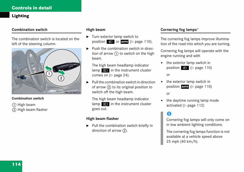
114
Controls in detail
Lightin
Combin
The comleft of th
Combina
1 High2 High
ornering fog lamps*
he cornering fog lamps improve illumina-on of the road into which you are turning.
ornering fog lamps will operate with the ngine running and with
the exterior lamp switch in position B (� page 110)
or
the exterior lamp switch in position U (� page 110)
or
the daytime running lamp mode activated (� page 112)
iCornering fog lamps will only come on in low ambient lighting conditions.
The cornering fog lamps function is not available at a vehicle speed above 25 mph (40 km/h).
g
ation switch
bination switch is located on the e steering column.
tion switch
beam beam flasher
High beam
� Turn exterior lamp switch to position B or U (� page 110).
� Push the combination switch in direc-tion of arrow 1 to switch on the high beam.
The high beam headlamp indicator lamp A in the instrument cluster comes on (� page 24).
� Pull the combination switch in direction of arrow 2 to its original position to switch off the high beam.
The high beam headlamp indicator lamp A in the instrument cluster goes out.
High beam flasher
� Pull the combination switch briefly in direction of arrow 2.
C
Tti
Ce
�
�
�
115
Controls in detail
Lighting
Drivin
Switch
� Deplefttur
Theandare
Driving rearward
Switching on cornering fog lamps
� Place the gear selector lever (manual transmission: gearshift lever) in position R.
The inverse front fog lamp comes on automatically depending on the steering direction and steering angle.
Switching off cornering fog lamps
� Place the gear selector lever (manual transmission: gearshift lever) out of position R.
The respective front fog lamp goes out.
iTheautingeithlamalsothe
g forward
ing on cornering fog lamps
ending on whether you are turning or right, switch on the left or right n signal (� page 52).
respective front fog lamp comes on illuminates the road into which you turning.
Switching off cornering fog lamps
The combination switch for the turn signal resets automatically after major steering wheel movements. This will switch off the cornering fog lamps if they were activated by switching on the left or right turn signal.
If the turn signal should stay on after mak-ing the turn, the turn signal and cornering fog lamp can be switched off by returning the combination switch to its original posi-tion.
cornering fog lamps will come on omatically depending on the steer- angle, even if you did not switch on er turn signal. If the cornering fog ps came on automatically, they will go out automatically depending on
steering angle.
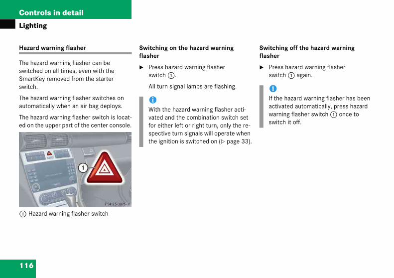
116
Controls in detail
Lightin
Hazard
The hazaswitchedSmartKeswitch.
The hazaautomat
The hazaed on th
1 Haza
witching off the hazard warning asher
Press hazard warning flasher switch 1 again.
iIf the hazard warning flasher has been activated automatically, press hazard warning flasher switch 1 once to switch it off.
g
warning flasher
rd warning flasher can be on all times, even with the y removed from the starter
rd warning flasher switches on ically when an air bag deploys.
rd warning flasher switch is locat-e upper part of the center console.
rd warning flasher switch
Switching on the hazard warning flasher
� Press hazard warning flasher switch 1.
All turn signal lamps are flashing.
Sfl
�
iWith the hazard warning flasher acti-vated and the combination switch set for either left or right turn, only the re-spective turn signals will operate when the ignition is switched on (� page 33).

117
Controls in detail
Lighting
Interio
The cocontro
1 Rea2 Rig3 Roc
sys4 Lef
Deactivating automatic control
� Press the = symbol on rocker switch 3.
The interior lighting remains switched off, even when you
� unlock the vehicle
� open a door
� remove the SmartKey from the starter switch
r lighting
ntrols are located in the overhead l panel.
r interior lightsht front reading lampker switch for automatic control temt front reading lamp
Activating automatic control
� Press the rocker switch 3 to center position.
Interior lamps are switched on in dark-ness, when you
� unlock the vehicle
� open a door
� remove the SmartKey from starter switch
The interior lamps are switched off follow-ing a preset time, see “Setting interior lighting delayed shut-off” (� page 147).
iIf the door remains open, the interior lamps switch off automatically after approximately five minutes, when the SmartKey is removed or in the starter switch position 0.
An interior lamp switched on manually does not go out automatically.
118
Controls in detail
Lightin
Manual
Switchinoff
� Presswitc
The f
� Prespositcont
Switchin
� Pres
The lcom
� Pres
The lcom
iThe setting selected for the interior lighting is used for the trunk lighting as well.
If you leave the trunk lid open for an ex-tended period of time, the trunk light-ing will switch off automatically after approximately ten minutes.
g
control
g all front interior lights on and
s the W symbol on rocker h 3.
ront interior lights come on.
s rocker switch 3 to center ion to activate the automatic rol.
g rear interior lights on and off
s button V.
ights in the rear passenger partment come on.
s button V again.
ights in the rear passenger partment go out.
Switching right front reading lamp on and off
� Press right button X.
The right reading lamp comes on.
� Press right button X again.
The right reading lamp goes out.
Switching left front reading lamp on and off
� Press left button X.
The left reading lamp comes on.
� Press left button X again.
The left reading lamp goes out.

119
Controls in detail
Instrument cluster
�Foclu
1
Thyo
�
�
�
�
Yoseof
To brighten illumination
� Turn reset button 1 clockwise.
The instrument cluster illumination will brighten.
To dim illumination
� Turn reset button 1 counterclock-wise.
The instrument cluster illumination will dim.
Instrur a full vster, se
Reset
e instruu
open a
switch
press
switch
u can cttings inthe con
ment clusteriew illustration of the instrument e “At a glance” (� page 24).
button
ment cluster is activated when
door
on the ignition (� page 33)
reset button 1
on the exterior lamps
hange the instrument cluster the instrument cluster submenu trol system (� page 137).
Instrument cluster illumination
Use reset button 1 to adjust the illumination brightness for the instrument cluster.
iThe instrument cluster illumination is dimmed or brightened automatically to suit ambient light conditions.
The instrument cluster illumination will also be adjusted automatically when you switch on the vehicle’s exterior lamps.

120
Controls in detail
Instrum
Coolant
The cooleft side(� page
uring severe operating conditions, e.g. top-and-go traffic, the coolant tempera-re may rise close to 248°F (120°C).
he engine should not be operated with e coolant temperature above 248°F 20°C). Doing so may cause serious
ngine damage which is not covered by the ercedes-Benz Limited Warranty.
ent cluster
temperature gauge
lant temperature gauge is on the in the instrument cluster 25).
Dstu
Tth(1eM
Warning! G
� Driving when your engine is badly overheated can cause some fluids which may have leaked into the engine compartment to catch fire. You could be seriously burned.
� Steam from an overheated engine can cause serious burns and can occur just by opening the hood. Stay away from the engine if you see or hear steam com-ing from it.
Turn off the engine, get out of the vehicle and do not stand near the vehicle until the engine has cooled down.

121
Controls in detail
Instrument cluster
Trip od
� Maodomu
� If itor ÿwh(�
� Preinsthe
Outside temperature indicator
Warning! G
The outside temperature indicator is not de-signed to serve as an ice-warning device and is therefore unsuitable for that purpose.
Indicated temperatures just above the freez-ing point do not guarantee that the road sur-face is free of ice. The road may still be icy, especially in wooded areas or on bridges.
ometer
ke sure you are viewing the trip meter and main odometer in the
ltifunction display (� page 123).
is not displayed, press button è on the multifunction steering
eel until the trip odometer appears page 124).
ss and hold the reset button in the trument cluster (� page 119) until trip odometer is reset.
Tachometer
The red marking on the tachometer (� page 24) denotes excessive engine speed.
To help protect the engine, the fuel supply is interrupted if the engine is operated within the red marking.
!Avoid driving at excessive engine speeds, as it may result in serious engine damage that is not covered by the Mercedes-Benz Limited Warranty.
122
Controls in detail
Instrum
The outsmultifuninformatindicateCelsiussee “Sel(� page
The temfront busensor cheat durmeans ttemperaparison the sensdisplays
ent cluster
ide temperature is indicated in the ction display (� page 123). For ion on how to select the unit of the d temperature, i.e. degrees (°C) or degrees Fahrenheit (°F), ecting temperature display mode” 137).
perature sensor is located in the mper area. Due to its location, the an be affected by road or engine ing idling or slow driving. This hat the accuracy of the displayed ture can only be verified by com-to a thermometer placed next to or, not by comparison to external (e.g. bank signs, etc.).
When moving the vehicle into colder ambi-ent temperatures (e.g. when leaving your garage), you will notice a delay before the lower temperature is displayed.
A delay also occurs when ambient temper-atures rise. This prevents inaccurate tem-perature indications caused by heat radiated from the engine during idling or slow driving.

123
Controls in detail
Control system
�Ththeturen
�
�
Fosynefordis
Multifunction display
1 Trip odometer2 Main odometer3 Current program mode (automatic
transmission*)4 Current gear selector lever
position/gear range (automatic trans-mission*)
5 Digital clock6 Status indicator (outside tempera-
ture/digital speedometer)
Contre contr Smartned to ables y
call up
chang
r exampstem toxt due f messaplay, a
iThe di(radio Englisselect
ol systemol system is activated as soon as Key in the starter switch is position 1. The control system ou to
information about your vehicle
e vehicle settings
le, you can use the control find out when your vehicle is or service, to set the language ges in the instrument cluster nd much more.
The control system relays information to the multifunction display.
splays for the audio systems and CD player) will appear in h, regardless of the language ed.
Warning! G
A driver’s attention to the road and traffic conditions must always be his/her primary focus when driving.
For your safety and the safety of others, selecting features through the multifunction steering wheel should only be done by the driver when traffic and road conditions permit it to be done safely.
Bear in mind that at a speed of just 30 mph (approximately 50 km/h), your vehicle is covering a distance of 44 feet (approximately 14 m) every second.
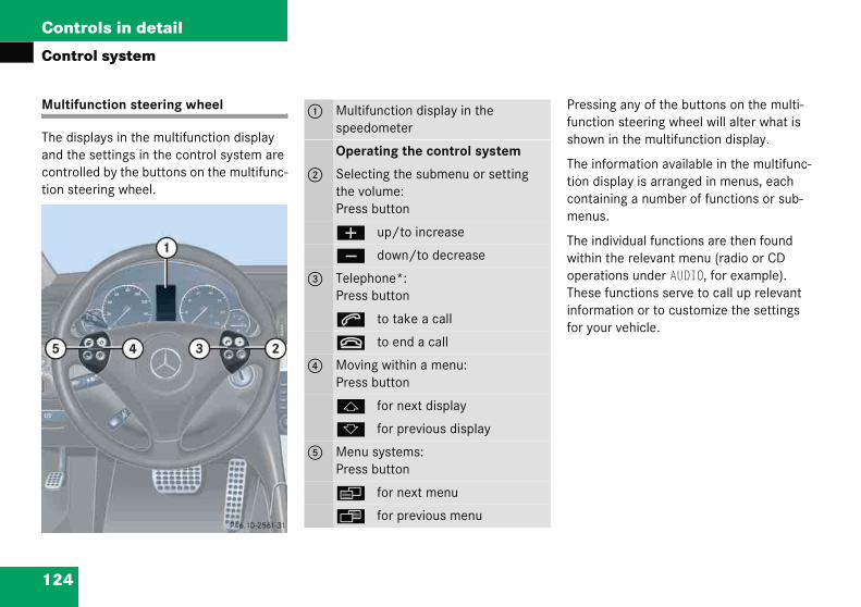
124
Controls in detail
Contro
Multifu
The dispand the controlletion stee
ressing any of the buttons on the multi-nction steering wheel will alter what is
hown in the multifunction display.
he information available in the multifunc-on display is arranged in menus, each ontaining a number of functions or sub-enus.
he individual functions are then found ithin the relevant menu (radio or CD perations under AUDIO, for example). hese functions serve to call up relevant formation or to customize the settings r your vehicle.
l system
nction steering wheel
lays in the multifunction display settings in the control system are d by the buttons on the multifunc-ring wheel.
Pfus
Tticm
TwoTinfo
1 Multifunction display in the speedometer
Operating the control system
2 Selecting the submenu or setting the volume:Press button
æ up/to increase
ç down/to decrease
3 Telephone*:Press button
s to take a call
t to end a call
4 Moving within a menu:Press button
j for next display
k for previous display
5 Menu systems:Press button
è for next menu
ÿ for previous menu
125
Controls in detail
Control system
It is hefunctioarrang
� If yrepme
� If yrepfunthe
The number of menus available in the sys-tem depends on which optional equipment is installed in your vehicle.
The menus are described on the following pages.
lpful to think of the menus, and the ns within each menu, as being ed in a circular pattern.
ou press button è or ÿ eatedly, you will pass through each nu one after the other.
ou press button k or j eatedly, you will pass through each ction display, one after the other, in current menu.
In the Settings menu, instead of functions you will find a number of submenus for calling up and changing settings. For instructions on using these submenus, see “Submenus in the Settings menu” (� page 134).

126
Controls in detail
Contro
Menus he table on the next page provides an verview of the individual menus.
l system
This is what you will see when you scroll through the menus.
To

127
Controls in detail
Control system
Menus
Me Menu 6 Menu 7
Stadis
Trip computer Telephone*
(� 3) (� page 151) (� page 153)
Com
man
ds/s
ubm
enus
Digspeouttur
tory Fuel consump-tion statistics af-ter start
Load phone book
Canandis
clus-u
Fuel consump-tion statistics since the last reset
Search for name in phone book
Chlev
Call up range
e
, submenus and functions
nu 1 Menu 2 Menu 3 Menu 4 Menu 5
ndard play
AUDIO NAV* Vehicle status message memory
Settings
page 128) (� page 129) (� page 131) (� page 132) (� page 13
ital edometer or side tempera-e
Select radio sta-tion
Activate route guidance
Call up vehicle mal-function, warning and system status messages stored in memory
Reset to facsettings
ll up mainte-ce service
play
Select satellite radio station* (USA only)
Instrument ter submen
eck engine oil el
Operate the CD player*
Time/Date submenu
Lighting submenu
Vehicle submenu
Conveniencsubmenu
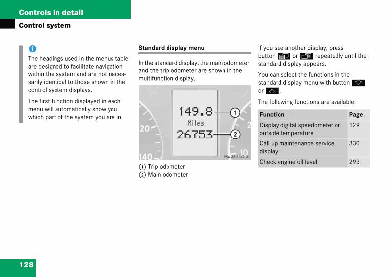
128
Controls in detail
Contro
you see another display, press utton è or ÿ repeatedly until the tandard display appears.
ou can select the functions in the tandard display menu with button k r j .
he following functions are available:
iThe hare dwithisarilycont
The fmenwhic unction Page
isplay digital speedometer or utside temperature
129
all up maintenance service isplay
330
heck engine oil level 293
l system
Standard display menu
In the standard display, the main odometer and the trip odometer are shown in the multifunction display.
1 Trip odometer2 Main odometer
Ifbs
Yso
T
eadings used in the menus table esigned to facilitate navigation n the system and are not neces- identical to those shown in the
rol system displays.
irst function displayed in each u will automatically show you h part of the system you are in. F
Do
Cd
C

129
Controls in detail
Control system
Displatempe
� Preuntin t
Thethe
1 Dig
AUDIO menu
The functions in the AUDIO menu operate the audio equipment which you currently have turned on.
If no audio equipment is currently turned on, the message AUDIO OFF appears in the multifunction display.
The following functions are available:
Function Page
Select radio station 130
Select satellite radio station* (USA only)
130
Operate CD player* 131
y digital speedometer or outside rature
ss button j or k repeatedly il the digital speedometer appears he multifunction display.
current vehicle speed is shown in multifunction display.
ital speedometer
iYou can have the outside temperature displayed instead of the digital speed-ometer. You can select the setting in the submenu Instr.Cl. via the function Status line display (� page 138).

130
Controls in detail
Contro
Select r
� TurnVehiRefeinstr
� Presuntilappe
1 Wave2 Stati
elect satellite radio station* SA only)
he satellite radio is treated as a radio pplication.
Select satellite radio with the corresponding soft key (SAT) in the radio menu.
SAT mode and preset numberChannel name or number
Press button k or j repeatedly until the desired channel is found.
l system
adio station
on the radio (� page 198). cles with COMAND*: r to separate operating uctions.
s button è or ÿ repeatedly the currently tuned station ars in the multifunction display.
band settingon frequency
� Press button k or j repeatedly until the desired station is found.
S(U
Ta
�
12
�
iYou can only store new stations using the corresponding feature on the radio (� page 206).
Vehicles with COMAND*: Refer to separate operating instructions.
You can also operate the radio in the usual manner.

131
Controls in detail
Control system
Opera
� TurCDVehRefins
� Preuntbeimu
NAV* menu
The NAV menu contains the functions needed to operate your navigation system.
� Press button è or ÿ repeatedly until the message NAV appears in the multifunction display.
� If the navigation system is switched off, the message NAV OFF appears in the multifunction display.
� If the navigation system is on, different messages, depending on the current state of the navigation system, appear in the multifunction display.
Please refer to the COMAND* manual for instructions on how to activate the route guidance system*.
iForoperad
VehRefins
te the CD player
n on the radio and select the player (� page 213).icles with COMAND*:er to separate operating tructions.
ss button è or ÿ repeatedly il the settings for the CD currently ng played appear in the ltifunction display.
1 Current CD (for CD changer*)2 Current track
� Press button k or j repeatedly until the desired track is selected.
more information on satellite radio ration, see “Introduction to satellite io* (USA only)” (� page 208).
icles with COMAND*: er to separate operating tructions.
iTo select a CD from the magazine, press a number on the audio system or the COMAND* system key pad located in the center dashboard.
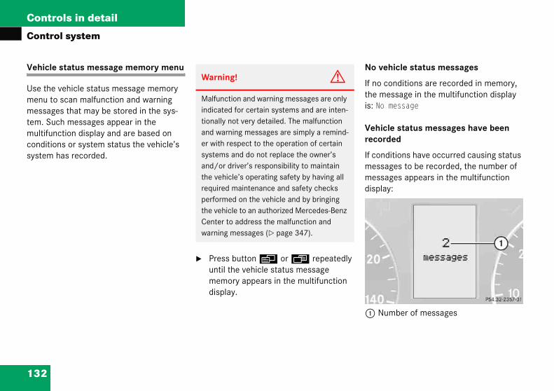
132
Controls in detail
Contro
Vehicle
Use the menu tomessagetem. Sucmultifunconditiosystem
o vehicle status messages
no conditions are recorded in memory, e message in the multifunction display : No message
ehicle status messages have been ecorded
conditions have occurred causing status essages to be recorded, the number of essages appears in the multifunction
isplay:
Number of messages
l system
status message memory menu
vehicle status message memory scan malfunction and warning s that may be stored in the sys-h messages appear in the
ction display and are based on ns or system status the vehicle’s has recorded.
� Press button è or ÿ repeatedly until the vehicle status message memory appears in the multifunction display.
N
Ifthis
Vr
Ifmmd
1
Warning! G
Malfunction and warning messages are only indicated for certain systems and are inten-tionally not very detailed. The malfunction and warning messages are simply a remind-er with respect to the operation of certain systems and do not replace the owner’s and/or driver’s responsibility to maintain the vehicle’s operating safety by having all required maintenance and safety checks performed on the vehicle and by bringing the vehicle to an authorized Mercedes-Benz Center to address the malfunction and warning messages (� page 347).

133
Controls in detail
Control system
� Pre
Thedishavwame(�
Shouldconditimessation disstarterremove
Resetting all settings
You can reset all the functions of all submenus to the factory settings.
� Press the reset button in the instrument cluster (� page 119) for approximately three seconds.
The request to press the reset button once more to confirm appears in the multifunction display.
� Press the reset button once more.
The functions of all the submenus will reset to factory settings.
iThewillSmposhigmu
ss button k or j .
stored messages will now be played in the order in which they e occurred. For malfunction and
rning messages, see “Vehicle status ssages in the multifunction display” page 347).
the vehicle’s system record any ons while driving, the number of ges will reappear in the multifunc-play when the SmartKey in the
switch is turned to position 0 or d from the starter switch.
Settings menu
In the Settings menu there are two functions:
� The function Reset to factory settings, with which you can reset all the settings to the original factory settings.
� A collection of submenus with which you can make individual settings for your vehicle.
� Press button è or ÿ repeatedly until the Settings menu appears in the multifunction display.
vehicle status message memory be cleared when you turn the artKey in the starter switch to ition 1 or 2. You will then only see
h-priority messages in the ltifunction display (� page 347).

134
Controls in detail
Contro
he submenus are arranged by hierarchy. croll down with button ç, scroll up ith button æ.
ove within the submenus with utton k or j to the individual nctions.
he settings themselves are made with utton æ or ç.
iThe sbe reby prtimethe Smult
For sfunc
� tL
� tC
l system
Submenus in the Settings menu
� Press button k or j.
The collection of the submenus appears in the multifunction display.
� Press button ç .
The selection marker moves to the next submenu.
TSw
Mbfu
Tb
ettings you have changed will not set unless you confirm the action essing the reset button a second
. After approximately five seconds, ettings menu reappears in the ifunction display.
afety reasons, the following tions are not reset while driving:
he Hdlamp mode function in the ighting submenu
he Key dependency function in the onvenience submenu

135
Controls in detail
Control system
Resett
For eacfunctio
� Mo
� Prethema
Theoncmu
� Pre
All to f
iThebe by timpresecrea
ing the functions of a submenu
h submenu you can reset all the ns to the factory settings.
ve to a function in the submenu.
ss the reset button (� page 119) in instrument cluster for approxi-tely three seconds.
request to press the reset button e more to confirm appears in the ltifunction display.
ss the reset button once more.
functions of the submenu will reset actory settings.
settings you have changed will not reset unless you confirm the action pressing the reset button a second e. Approximately five seconds after ssing the reset button for the ond time, the Settings menu ppears in the multifunction display.
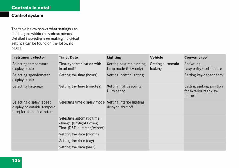
136
Controls in detail
Contro
The tablbe chanDetailedsettingspages.
Instrum le Convenience
Selectindisplay
g automatic g
Activating easy-entry/exit feature
Selectindisplay
Setting key-dependency
Selectin Setting parking position for exterior rear view mirror
Selectindisplay ture) fo
l system
e below shows what settings can ged within the various menus. instructions on making individual can be found on the following
ent cluster Time/Date Lighting Vehic
g temperature mode
Time synchronization with head unit*
Setting daytime running lamp mode (USA only)
Settinlockin
g speedometer mode
Setting the time (hours) Setting locator lighting
g language Setting the time (minutes) Setting night security illumination
g display (speed or outside tempera-r status indicator
Selecting time display mode Setting interior lighting delayed shut-off
Selecting automatic time change (Daylight Saving Time (DST) summer/winter)
Setting the date (month)
Setting the date (day)
Setting the date (year)

137
Controls in detail
Control system
Instru
AccessSettinsubmedisplay
The fol
Selecting speedometer display mode
� Move the selection marker with button æ or ç to the Instr.Cl. submenu.
� Press button j or k repeatedly until the message Disp.Unit Speed/odo appears in the multifunction display.
The selection marker is on the current setting.
� Press button æ or ç to set speedometer unit to km or Miles.
Funct
Selectmode
Selectmode
Select
Selector outtus ind
ment cluster submenu
the Instr.Cl. submenu via the gs menu. Use the Instr.Cl. nu to change the instrument cluster settings.
lowing functions are available:
Selecting temperature display mode
� Move the selection marker with button æ or ç to the Instr.Cl. submenu.
� Press button j or k repeatedly until the message Temperature indicator appears in the multifunction display.
The selection marker is on the current setting.
� Press button æ or ç to set tem-perature unit to °C (degrees Celsius) or °F (degrees Fahrenheit).
ion Page
ing temperature display 137
ing speedometer display 137
ing language 138
ing display (speed display side temperature) for sta-icator
138
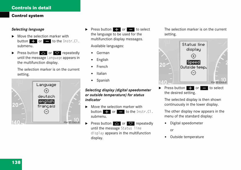
138
Controls in detail
Contro
Selectin
� Movebuttosubm
� Presuntilthe m
The ssetti
The selection marker is on the current setting.
Press button æ or ç to select the desired setting.
The selected display is then shown continuously in the lower display.
The other display now appears in the menu of the standard display:
� Digital speedometer
or
� Outside temperature
l system
g language
the selection marker with n æ or ç to the Instr.Cl. enu.
s button j or k repeatedly the message Language appears in
ultifunction display.
election marker is on the current ng.
� Press button æ or ç to select the language to be used for the multifunction display messages.
Available languages:
� German
� English
� French
� Italian
� Spanish
Selecting display (digital speedometer or outside temperature) for status indicator
� Move the selection marker with button æ or ç to the Instr.Cl. submenu.
� Press button j or k repeatedly until the message Status line display appears in the multifunction display.
�

139
Controls in detail
Control system
Time/
AccessSettinsubmedisplayare ava
Setting the time (hours)
This function can be seen in vehicles with audio system, or in vehicles with COMAND* if the time synchronization with head unit* feature was set to Off.
� Move the selection marker with button æ or ç to the Time/Date submenu.
� Press button j or k repeatedly until the message Time Hours appears in the multifunction display.
Funct
Time shead u
Settin
Settin
Select
Select(Dayligsumm
Settin
Settin
Settin
iVehicles with COMAND*:For information on setting the time in COMAND, refer to the separate COMAND operating instructions.
��
Date submenu
the Time/Date submenu via the gs menu. Use the Time/Date nu to change the instrument cluster settings. The following functions ilable:
Time synchronization with head unit*
This function can only be seen on vehicles with COMAND* and navigation module*.
� Move the selection marker with button æ or ç to the Time/Date submenu.
� Press button j or k repeatedly until the message Time synchro. w/Head Unit appears in the multifunc-tion display.
The selection marker is on the current setting.
� Press button æ or ç to select the desired setting.
ion Page
ynchronization with nit*
139
g time (hours) 139
g time (minutes) 140
ing time display mode 141
ing automatic time change ht Saving Time (DST)
er/Standard Time winter)
141
g date (month) 141
g date (day) 142
g date (year) 143

140
Controls in detail
Contro
The ssetti
� Preshour
The selection marker is on the minute setting.
Press button æ or ç to set the minutes.
��
l system
election marker is on the hour ng.
s button æ or ç to set the .
Setting the time (minutes)
This function can be seen in vehicles with audio system, or in vehicles with COMAND* if the time synchronization with head unit* feature was set to Off.
� Move the selection marker with button æ or ç to the Time/Date submenu.
� Press button j or k repeatedly until the message Time Minutes appears in the multifunction display.
�
iVehicles with COMAND*:For information on setting the time in COMAND, refer to the separate COMAND operating instructions.
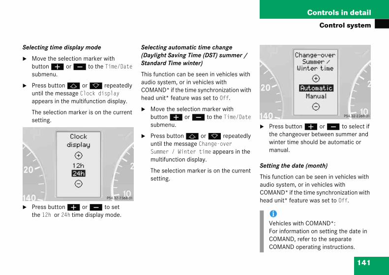
141
Controls in detail
Control system
Select
� Mobutsub
� Preuntapp
Theset
� Prethe
� Press button æ or ç to select if the changeover between summer and winter time should be automatic or manual.
Setting the date (month)
This function can be seen in vehicles with audio system, or in vehicles with COMAND* if the time synchronization with head unit* feature was set to Off.
iVehicles with COMAND*:For information on setting the date in COMAND, refer to the separate COMAND operating instructions.
ing time display mode
ve the selection marker with ton æ or ç to the Time/Date menu.
ss button j or k repeatedly il the message Clock display ears in the multifunction display.
selection marker is on the current ting.
ss button æ or ç to set 12h or 24h time display mode.
Selecting automatic time change (Daylight Saving Time (DST) summer / Standard Time winter)
This function can be seen in vehicles with audio system, or in vehicles with COMAND* if the time synchronization with head unit* feature was set to Off.
� Move the selection marker with button æ or ç to the Time/Date submenu.
� Press button j or k repeatedly until the message Change-over Summer / Winter time appears in the multifunction display.
The selection marker is on the current setting.
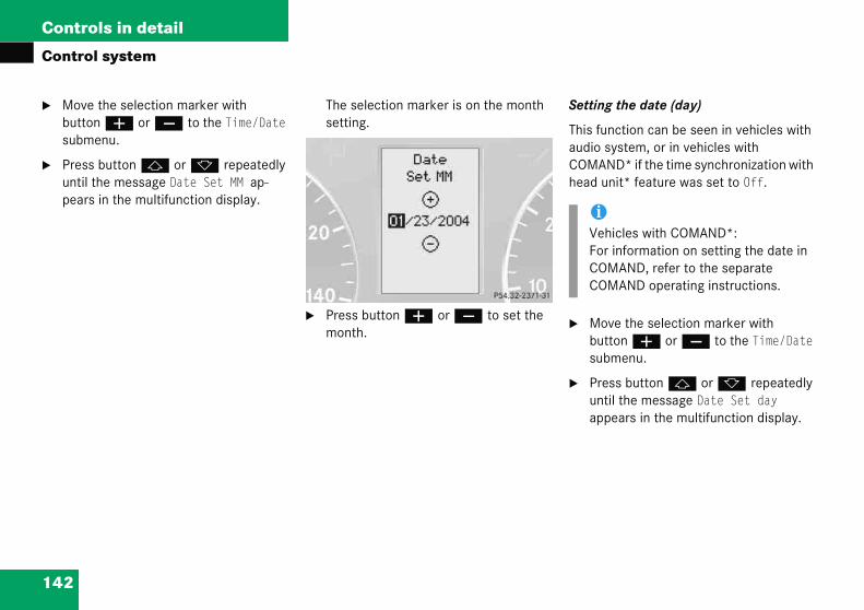
142
Controls in detail
Contro
� Movebuttosubm
� Presuntilpear
etting the date (day)
his function can be seen in vehicles with udio system, or in vehicles with OMAND* if the time synchronization with ead unit* feature was set to Off.
Move the selection marker with button æ or ç to the Time/Date submenu.
Press button j or k repeatedly until the message Date Set day appears in the multifunction display.
iVehicles with COMAND*:For information on setting the date in COMAND, refer to the separate COMAND operating instructions.
l system
the selection marker with n æ or ç to the Time/Date enu.
s button j or k repeatedly the message Date Set MM ap-s in the multifunction display.
The selection marker is on the month setting.
� Press button æ or ç to set the month.
S
TaCh
�
�
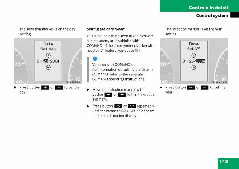
143
Controls in detail
Control system
Theset
� Preday
The selection marker is on the year setting.
� Press button æ or ç to set the year.
selection marker is on the day ting.
ss button æ or ç to set the .
Setting the date (year)
This function can be seen in vehicles with audio system, or in vehicles with COMAND* if the time synchronization with head unit* feature was set to Off.
� Move the selection marker with button æ or ç to the Time/Date submenu.
� Press button j or k repeatedly until the message Date Set YY appears in the multifunction display.
iVehicles with COMAND*:For information on setting the date in COMAND, refer to the separate COMAND operating instructions.
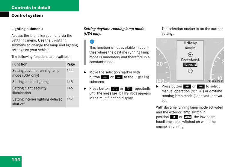
144
Controls in detail
Contro
Lighting
Access tSettingsubmensettings
The follo
The selection marker is on the current setting.
Press button æ or ç to select manual operation (Manual) or daytime running lamp mode (Constant) activat-ed.
ith daytime running lamp mode activated nd the exterior lamp switch in osition M or U, the low beam eadlamps are switched on when the ngine is running.
Functio
Setting mode (U
Setting
Setting illumina
Setting shut-off
l system
submenu
he Lighting submenu via the s menu. Use the Lighting u to change the lamp and lighting on your vehicle.
wing functions are available:
Setting daytime running lamp mode (USA only)
� Move the selection marker with button æ or ç to the Lighting submenu.
� Press button j or k repeatedly until the message Hdlamp mode appears in the multifunction display.
�
Waphe
n Page
daytime running lamp SA only)
144
locator lighting 145
night security tion
146
Interior lighting delayed 147
iThis function is not available in coun-tries where the daytime running lamp mode is mandatory and therefore in a constant mode.

145
Controls in detail
Control system
In low ing lam
� Par
� Tai
� Lic
� Sid
For morunnin(� pag
� Press button j or k repeatedly until the message Surround lighting appears in the multifunction display.
The selection marker is on the current setting.
� Press button æ or ç to switch the locator lighting function On.
� Turn the exterior lamp switch to position U when exiting the vehicle (� page 110).
The locator lighting feature is activated.
iForLig(�deamo
ThemuLigresdri
ambient light conditions the follow-ps will switch on additionally:
king lamps
l lamps
ense plate lamps
e marker lamps
re information on the daytime g lamp mode, see “Lighting” e 110).
Setting locator lighting
With the locator lighting feature activated and the exterior lamp switch in position U, the following lamps will switch on when the vehicle is unlocked with the SmartKey during darkness:
� Parking lamps
� Tail lamps
� License plate lamps
� Side marker lamps
� Front fog lamps
The locator lighting switches off when the driver’s door is opened.
If you do not open a door after unlocking with the SmartKey the lamps will switch off automatically after approximately 40 seconds.
� Move the selection marker with button æ or ç to the Lighting submenu.
safety reasons, resetting the hting submenu to factory settings page 135) while driving will not ctivate the daytime running lamp de.
following message appears in the ltifunction display:hting - Cannot be completely et to factory sets. while ving.
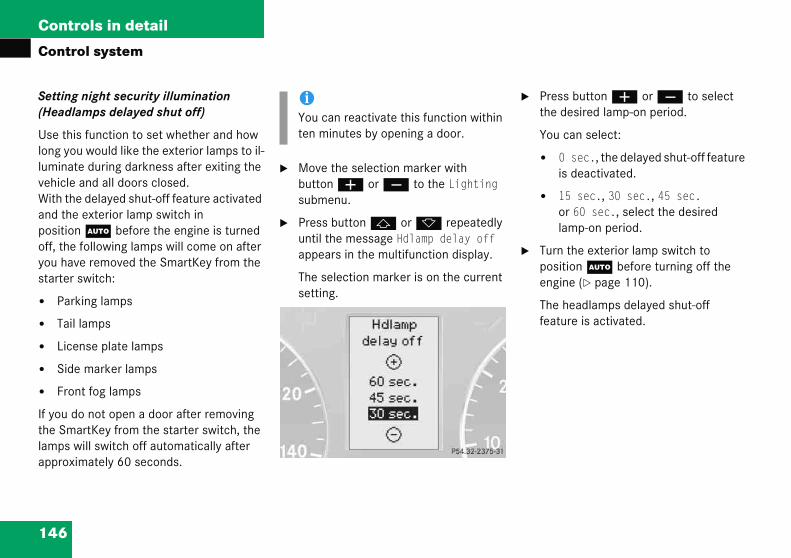
146
Controls in detail
Contro
Setting (Headla
Use thislong youluminatevehicle aWith theand the positionoff, the fyou havestarter s
� Park
� Tail l
� Licen
� Side
� Fron
If you dothe Smalamps wapproxim
Press button æ or ç to select the desired lamp-on period.
You can select:
� 0 sec., the delayed shut-off feature is deactivated.
� 15 sec., 30 sec., 45 sec. or 60 sec., select the desired lamp-on period.
Turn the exterior lamp switch to position U before turning off the engine (� page 110).
The headlamps delayed shut-off feature is activated.
l system
night security illumination mps delayed shut off)
function to set whether and how would like the exterior lamps to il- during darkness after exiting the nd all doors closed. delayed shut-off feature activated exterior lamp switch in U before the engine is turned ollowing lamps will come on after removed the SmartKey from the witch:
ing lamps
amps
se plate lamps
marker lamps
t fog lamps
not open a door after removing rtKey from the starter switch, the ill switch off automatically after ately 60 seconds.
� Move the selection marker with button æ or ç to the Lighting submenu.
� Press button j or k repeatedly until the message Hdlamp delay off appears in the multifunction display.
The selection marker is on the current setting.
�
�
iYou can reactivate this function within ten minutes by opening a door.

147
Controls in detail
Control system
You cadelaye
� BefSmpos
� Thepos
Thedeaas sta
The selection marker is on the current setting.
� Press button æ or ç to select the desired lamp-on period.
You can select:
� 0 sec., the delayed shut-off feature is deactivated.
� 5 sec., 10 sec., 15 sec. or 20 sec., the interior lighting delayed shut-off feature is activat-ed with the desired lamp-on period.
n temporarily deactivate the d shut-off feature:
ore exiting the vehicle, turn the artKey in the starter switch to ition 0.
n turn it to position 2 and back to ition 0.
delayed shut-off feature is ctivated. It will reactivate as soon
you reinsert the SmartKey in the rter switch.
Setting interior lighting delayed shut-off
Use this function to set whether and how long you would like the interior lighting to remain lit during darkness after you have removed the SmartKey from the starter switch.
� Move the selection marker with button æ or ç to the Lighting submenu.
� Press button j or k repeatedly until the message Int. light delay off appears in the multifunction display.
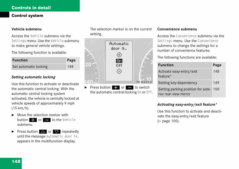
148
Controls in detail
Contro
Vehicle
Access tSettingto make
The follo
Setting
Use thisthe autoautomatactivatevehicle s(15 km/
� Movebuttosubm
� Presuntilappe
onvenience submenu
ccess the Convenience submenu via the ettings menu. Use the Convenience ubmenu to change the settings for a umber of convenience features.
he following functions are available:
ctivating easy-entry/exit feature*
se this function to activate and deacti-ate the easy-entry/exit feature
page 100).
Functio
Set auto unction Page
ctivate easy-entry/exit eature*
148
etting key-dependency 149
etting parking position for exte-ior rear view mirror
150
l system
submenu
he Vehicle submenu via the s menu. Use the Vehicle submenu general vehicle settings.
wing function is available:
automatic locking
function to activate or deactivate matic central locking. With the ic central locking system d, the vehicle is centrally locked at peeds of approximately 9 mph h).
the selection marker with n æ or ç to the Vehicle enu.
s button j or k repeatedly the message Automatic door lk. ars in the multifunction display.
The selection marker is on the current setting.
� Press button æ or ç to switch the automatic central locking On or Off.
C
ASsn
T
A
Uv(�
n Page
matic locking 148 F
Af
S
Sr

149
Controls in detail
Control system
The following settings are available for the easy-entry/exit feature:
Setting key-dependency
Use this function to set whether the memory settings for the seats, the steering wheel and the mirrors should be stored separately for each SmartKey (� page 107).
� Move the selection marker with button æ or ç to the Convenience submenu.
� Press button j or k repeatedly until the message Key dependency appears in the multifunction display.
Warn
You mtrappewheeltry/ex
To cando on
� Pr(�
� M(�
� Pr(�
Do nohicle, Childrunintefeaturand/o
Off The easy-entry/exit feature is deactivated
Steer. Column Only the steering column is moved
St.col.+seat Both the steering column and the seat are moved
��
� Move the selection marker with button æ or ç to the Convenience submenu.
� Press button j or k repeatedly until the message Easy-entry feature appears in the multifunction display.
The selection marker is on the current setting.
� Press æ or ç to change the easy-entry/exit setting.
ing! G
ust make sure no one can become d or injured by the moving steering
and driver’s seat when the easy-en-it feature is activated.
cel seat/steering wheel movement, e of the following:
ess seat adjustment switch* page 38).
ove steering column stalk* page 41).
ess the memory position switch* page 108).
t leave children unattended in the ve-or with access to an unlocked vehicle. en could open the driver’s door and ntionally activate the easy-entry/exit e, which could result in an accident r serious personal injury.
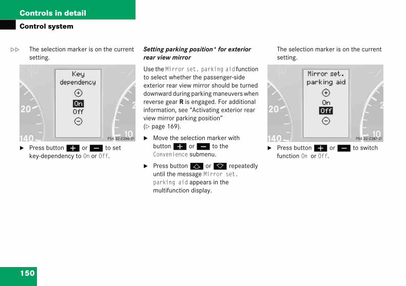
150
Controls in detail
Contro
The ssetti
� Preskey-d
The selection marker is on the current setting.
Press button æ or ç to switch function On or Off.
��
l system
election marker is on the current ng.
s button æ or ç to set ependency to On or Off.
Setting parking position* for exterior rear view mirror
Use the Mirror set. parking aid function to select whether the passenger-side exterior rear view mirror should be turned downward during parking maneuvers when reverse gear R is engaged. For additional information, see “Activating exterior rear view mirror parking position” (� page 169).
� Move the selection marker with button æ or ç to the Convenience submenu.
� Press button j or k repeatedly until the message Mirror set. parking aid appears in the multifunction display.
�

151
Controls in detail
Control system
Trip co
Use thstatisti
The fol
Fuel consumption since last reset
� Press button ÿ or è repeatedly until the first function of the Trip computer menu appears in the multifunction display.
� Press button j or k repeatedly until the message After reset appears in the multifunction display.
1 Distance driven since last reset2 Time elapsed since last reset3 Average speed since last reset4 Average fuel consumption since last
reset
Funct
Fuel costart
Fuel csince
Call up
��
mputer menu
e trip computer menu to call up cal data on your vehicle.
lowing information is available:
Fuel consumption statistics after start
� Press button ÿ or è repeatedly until the first function of the Trip computer menu appears in the multifunction display.
� Press button j or k repeatedly until the message After start appears in the multifunction display.
1 Distance driven since start2 Time elapsed since start3 Average speed since start4 Average fuel consumption since start
ion Page
nsumption statistics after 151
onsumption statistics last reset
151
range (distance to empty) 152
152
Controls in detail
Contro
all up range (distance to empty)
Press button ÿ or è repeatedly until the first function of the trip computer menu appears in the multifunction display.
Press button j or k repeatedly until the message Distance appears in the multifunction display.
The calculated range based on the current fuel tank level appears in the multifunction display.
iAll stenginfour startremo
ReseSmawithi
��
l system
Resetting fuel consumption statistics
� Press button ÿ or è repeatedly until the first function of the trip computer menu appears in the multifunction display.
� Press button j or k repeatedly until the reading that you want to reset appears in the multifunction display.
� Press and hold the reset button in the instrument cluster (� page 119) until the value is reset to 0.
C
�
�
atistics stored since the last e start will be reset approximately
hours after the SmartKey in the er switch is turned to position 0 or ved from the starter switch.
tting will not occur if you turn the rtKey back to position 1 or 2 n this time period.
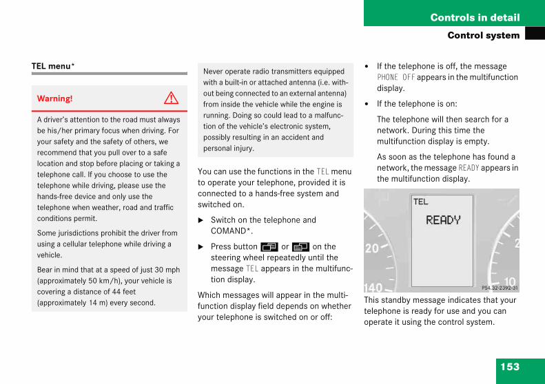
153
Controls in detail
Control system
TEL m � If the telephone is off, the message PHONE OFF appears in the multifunction display.
� If the telephone is on:
The telephone will then search for a network. During this time the multifunction display is empty.
As soon as the telephone has found a network, the message READY appears in the multifunction display.
This standby message indicates that your telephone is ready for use and you can operate it using the control system.
Warn
A drivbe hisyour srecomlocatitelephtelephhandstelephcondi
Someusing vehicl
Bear i(approcover(appro
enu*
You can use the functions in the TEL menu to operate your telephone, provided it is connected to a hands-free system and switched on.
� Switch on the telephone and COMAND*.
� Press button ÿ or è on the steering wheel repeatedly until the message TEL appears in the multifunc-tion display.
Which messages will appear in the multi-function display field depends on whether your telephone is switched on or off:
ing! G
er’s attention to the road must always /her primary focus when driving. For afety and the safety of others, we mend that you pull over to a safe
on and stop before placing or taking a one call. If you choose to use the one while driving, please use the -free device and only use the one when weather, road and traffic
tions permit.
jurisdictions prohibit the driver from a cellular telephone while driving a e.
n mind that at a speed of just 30 mph ximately 50 km/h), your vehicle is
ing a distance of 44 feet ximately 14 m) every second.
Never operate radio transmitters equipped with a built-in or attached antenna (i.e. with-out being connected to an external antenna) from inside the vehicle while the engine is running. Doing so could lead to a malfunc-tion of the vehicle’s electronic system, possibly resulting in an accident and personal injury.

154
Controls in detail
Contro
Answer
When yocalls, yothe multthe mes
� Pres
You duramult
ialing a number from the phone book
your telephone is ready to receive calls, ou may select and dial a number from the hone book at any time.
Press button ÿ or è repeatedly until the message TEL appears in the multifunction display.
Press button j or k .
The control system reads the phone book which is stored in the telephone. This may take up to 30 seconds. The message Please wait appears in the multifunction display.
When the message Please wait disappears, the phone book has been loaded.
l system
ing a call
ur telephone is ready to receive u can answer a call at any time. In ifunction display you will then see sage:
s button s .
have answered the call. The tion of the call appears in the ifunction display.
Ending a call
� Press button t.
You have ended the call. The standby message appears in the multifunction display.
D
Ifyp
�
�

155
Controls in detail
Control system
� Preuntmu
Theascord
1 Nam
� If no connection is made, the control system stores the dialed number in the redial memory.
ss button j or k repeatedly il the desired name appears in the ltifunction display.
stored names are displayed in ending or descending alphabetical er.
e from the phone book
� Press button s .
The system dials the selected phone number.
� If the connection is successful, the name of the party you called and the duration of the call will appear in the multifunction display.
iIf you press and hold button j or k for longer than one second, the system scrolls rapidly through the list of names until you release the button again.
Cancel the quick search mode by pressing button t.

156
Controls in detail
Contro
Redialin
The conrecentlyeliminatentire ph
� Presuntilmult
� Pres
The fappe
� Presuntilmult
� Pres
The cphon
l system
g
trol system stores the most dialed phone numbers. This es the need to search through your one book.
s button ÿ or è repeatedly the message TEL appears in the ifunction display.
s button s .
irst number in the redial memory ars in the multifunction display.
s button j or k repeatedly the desired name appears in the ifunction display.
s button s .
ontrol system dials the selected e number.
157
Controls in detail
Manual transmission
�Fomami
Warning! G
When leaving the vehicle, always remove the SmartKey from the starter switch, take it with you, and lock the vehicle. Do not leave children unattended in the vehicle, or with access to an unlocked vehicle. Children could move the gearshift lever, which could result in an accident and/or serious injury.
Warning! G
On slippery road surfaces, never downshift in order to obtain braking action. This could result in drive wheel slip and reduced vehi-cle control. Your vehicle’s ABS will not pre-vent this type of loss of control.
Manur more nual tr
ssion” (
al transmissioninformation on driving with a ansmission, see “Manual trans-� page 48).
Warning! G
For vehicles equipped with a manual trans-mission, getting out of your vehicle with the gearshift lever not engaged in 1st or reverse gear and parking brake engaged is danger-ous. Also, when parked on an incline, an en-gaged 1st or reverse gear alone may not prevent your vehicle from moving, possibly hitting people or objects.
Always set the parking brake in addition to engaging first or reverse gear (� page 56).
When parked on an incline, turn the front wheel towards the road curb.
Do not park this vehicle in areas where com-bustible materials such as grass, hay, or leaves can come into contact with the hot exhaust system, as these materials could be ignited and cause a vehicle fire.

158
Controls in detail
Manua
Gearshif
hifting into reverse
Stop the vehicle completely.
Fully depress clutch pedal.
Move the gearshift lever to the neutral position (no gear selected).
Move the gearshift lever to the left until you feel a certain resistance.
Push the gearshift lever past this resistance.
Then move the gearshift lever forward into position R.
!Only shift into reverse gear R, when the vehicle is stationary, as the transmis-sion could otherwise be damaged.
l transmission
t pattern for manual transmission
S
�
�
�
�
�
�
!When you are shifting into the 5th or 6th gear, make sure that you press the gearshift lever to the right. Other-wise, you could accidentally shift into the 3rd or 4th gear and damage the transmission.
Downshifting gears leading to overrevving the engine can result in engine damage that is not covered by the Mercedes-Benz Limited Warranty.
Never hold the vehicle stopped on a hill by using the clutch pedal. The clutch may be damaged which is not covered by the Mercedes-Benz Limited Warranty.
Do not exceed the engine speed limits. Refer to tachometer (� page 121) for engine speeds.
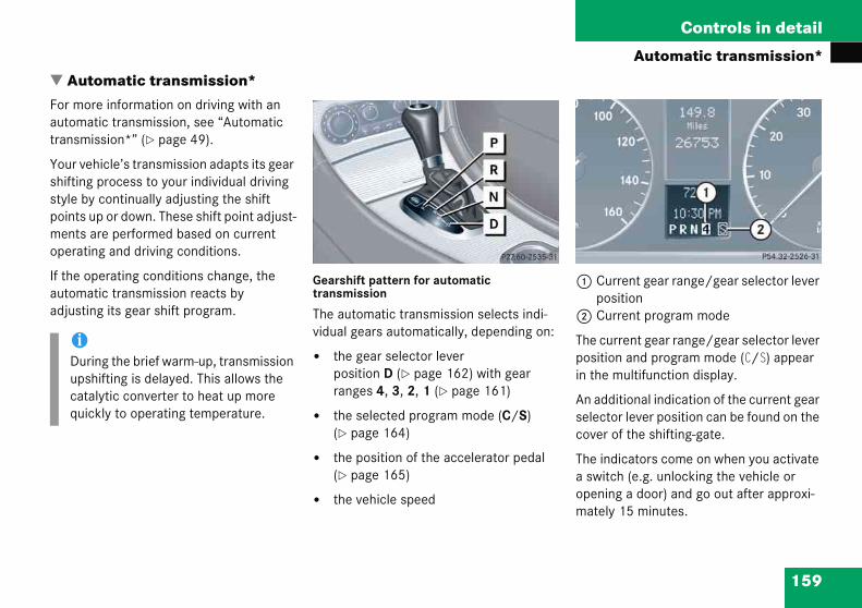
159
Controls in detail
Automatic transmission*
�Foautra
Yoshstypomeop
If tauad
1 Current gear range/gear selector lever position
2 Current program mode
The current gear range/gear selector lever position and program mode (C/S) appear in the multifunction display.
An additional indication of the current gear selector lever position can be found on the cover of the shifting-gate.
The indicators come on when you activate a switch (e.g. unlocking the vehicle or opening a door) and go out after approxi-mately 15 minutes.
Automr more tomaticnsmiss
ur vehicifting prle by cints up nts areerating
he opetomaticjusting
iDuringupshifcatalyquickl
atic transmission*information on driving with an transmission, see “Automatic ion*” (� page 49).
le’s transmission adapts its gear ocess to your individual driving
ontinually adjusting the shift or down. These shift point adjust- performed based on current and driving conditions.
rating conditions change, the transmission reacts by its gear shift program.
Gearshift pattern for automatic transmission
The automatic transmission selects indi-vidual gears automatically, depending on:
� the gear selector lever position D (� page 162) with gear ranges 4, 3, 2, 1 (� page 161)
� the selected program mode (C/S) (� page 164)
� the position of the accelerator pedal (� page 165)
� the vehicle speed
the brief warm-up, transmission ting is delayed. This allows the tic converter to heat up more y to operating temperature.

160
Controls in detail
Autom
When thpositionshifting
� limit
� chan
pshifting
Briefly press the gear selector lever to the right in the D+ direction.
he transmission will shift from the current ear to the next higher gear as permitted y the shift program. This action simul-neously extends the gear range of the ansmission.
Warni
It is danlever ouhigher tfirmly oaccelercould losomeonwhen thyour rig
iTo avoid overrevving the engine when the gear selector lever is moved to the D- direction, the transmission will not shift to a lower gear if the engine’s max. speed would be exceeded.
atic transmission*
e gear selector lever is in D, you can influence transmission
by:
ing the gear range
ging gears manually
One-touch gearshifting
Even with an automatic transmission you can change the gears manually when the gear selector lever is in position D.
Downshifting
� Briefly press the gear selector lever to the left in the D- direction.
The transmission will shift from the current gear to the next lower gear. This action simultaneously limits the gear range of the transmission (� page 161).
U
�
Tgbtatr
ng! G
gerous to shift the gear selector t of P or N if the engine speed is han idle speed. If your foot is not n the brake pedal, the vehicle could ate quickly forward or reverse. You se control of the vehicle and hit e or something. Only shift into gear e engine is idling normally and when ht foot is firmly on the brake pedal.
Warning! G
On slippery road surfaces, never downshift in order to obtain braking action. This could result in drive wheel slip and reduced vehicle control. Your vehicle’s ABS will not prevent this type of loss of control.

161
Controls in detail
Automatic transmission*
Cance
� Prein tthe
The tragear ra
Shiftin
� Prein t
The trathe geaacceleinvolve
Effect
ç The transmission shifts through second gear only.
Allows the use of engine’s braking power when driving:
� on steep downgrades
� in mountainous regions
� under extreme operating conditions
æ The transmission operates in first gear only.
For maximum use of engine’s braking effect on very steep or lengthy downgrades.
ling gear range limit
ss and hold the gear selector lever he D+ direction until D reappears in multifunction display.
nsmission will shift from the current nge directly to gear range D.
g into optimal gear range
ss and hold the gear selector lever he D- direction.
nsmission will automatically select r range suited for optimal
ration and deceleration. This will shifting down one or more gears.
Gear ranges
With the gear selector lever in position D, you can limit the transmission’s gear range by pressing the gear selector lever to the left (D-), and reverse the gear range limit by pressing the gear selector lever to the right (D+).
The selected gear range appears in the multifunction display. If you press on the accelerator when the engine has reached its rpm limit, the transmission will upshift beyond any gear range limit selected.
Effect
é The transmission shifts through fourth gear only.
è The transmission shifts through third gear only.
With this selection you can use the braking effect of the engine.
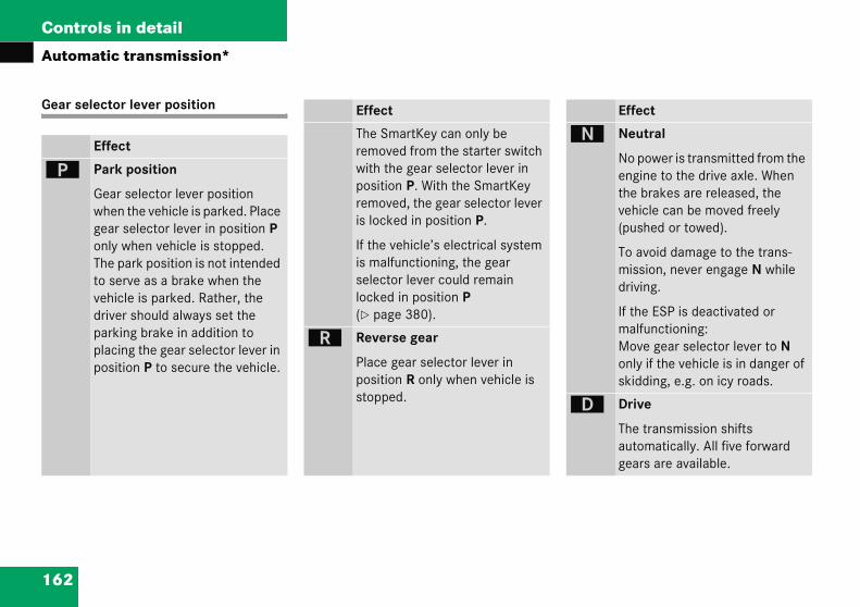
162
Controls in detail
Autom
Gear se
ì
Effect
Neutral
No power is transmitted from the engine to the drive axle. When the brakes are released, the vehicle can be moved freely (pushed or towed).
To avoid damage to the trans-mission, never engage N while driving.
If the ESP is deactivated or malfunctioning:Move gear selector lever to N only if the vehicle is in danger of skidding, e.g. on icy roads.
Drive
The transmission shifts automatically. All five forward gears are available.
atic transmission*
lector lever position
Effect
Park position
Gear selector lever position when the vehicle is parked. Place gear selector lever in position P only when vehicle is stopped. The park position is not intended to serve as a brake when the vehicle is parked. Rather, the driver should always set the parking brake in addition to placing the gear selector lever in position P to secure the vehicle.
Effect
The SmartKey can only be removed from the starter switch with the gear selector lever in position P. With the SmartKey removed, the gear selector lever is locked in position P.
If the vehicle’s electrical system is malfunctioning, the gear selector lever could remain locked in position P (� page 380).
í Reverse gear
Place gear selector lever in position R only when vehicle is stopped.
ë
ê

163
Controls in detail
Automatic transmission*
!Coaothin NthaMe
Warning! G
When leaving the vehicle, always remove the SmartKey from the starter switch, take it with you, and lock the vehicle. Do not leave children unattended in the vehicle, or with access to an unlocked vehicle. Children could move the gear selector lever from position P, which could result in an accident and/or serious personal injury.
sting the vehicle, or driving for any er reason with gear selector lever can result in transmission damage
t is not covered by the rcedes-Benz Limited Warranty.
Warning! G
Getting out of your vehicle with the gear selector lever not fully engaged in position P is dangerous. Also, position P alone is not intended to or capable of preventing your vehicle from moving, possibly hitting people or objects.
Always set the parking brake in addition to shifting to position P (� page 50).
When parked on an incline, turn the front wheels towards the road curb.
Do not park this vehicle in areas where com-bustible materials such as grass, hay, or leaves can come into contact with the hot exhaust system, as these materials could be ignited and cause a vehicle fire.

164
Controls in detail
Autom
Automa
The proglocated console.
1 Prog
C Comfo
S Sport
Press program mode selector switch 1 repeatedly until the letter of the desired program mode appears in the multifunction display (� page 159).
Select C for comfort driving:
� The vehicle starts out in second gear (both forward and reverse) for gentler starts. This does not apply if full throttle is applied or gear range 1 is selected.
� Traction and driving stability are improved on icy roads.
� Upshifts occur earlier even when you give more gas. The engine then operates at lower rpms and the wheels are less likely to spin.
atic transmission*
tic shift program
ram mode selector switch is on the lower part of the center
ram mode selector switch
rt For comfort driving
For standard driving
�!Never change the program mode when the gear selector lever is out of position P. This could result in a change of driving characteristics for which you may not be prepared.
iThe last selected program mode (S or C) is switched on when the engine is restarted in the automatic program mode.

165
Controls in detail
Automatic transmission*
Drivin
Accele
Your dtransm
Less th
More t
Kickdo
Use kicaccele
� Preres
Thegea
� Easrea
The
Maneuvering
When you maneuver in tight areas, e.g. when pulling into parking space:
� Control the vehicle speed by gradually releasing the brakes.
� Accelerate gently.
� Never abruptly step on the accelerator.
Working on the vehicle
Warning! G
When working on the vehicle, set the parking brake and move gear selector lever to position P. Otherwise the vehicle could roll away.
g tips
rator position
riving style influences the ission’s shifting behavior:
rottle Earlier upshifting
hrottle Later upshifting
wn
kdown when you want maximum ration.
ss the accelerator past the point of istance.
transmission shifts into a lower r.
e on the accelerator when you have ched the desired speed.
transmission shifts up again.
Stopping
When you stop briefly, e.g. at traffic lights:
� Leave the transmission in gear.
� Hold the vehicle with the brake.
When you stop longer with the engine idling or on an uphill gradient:
� Move the gear selector lever to position P.
� Set the parking brake.
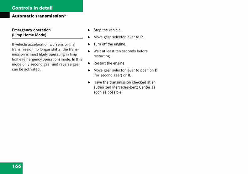
166
Controls in detail
Autom
Emerge(Limp H
If vehicletransmismission home (emode oncan be a
atic transmission*
ncy operation ome Mode)
acceleration worsens or the sion no longer shifts, the trans-is most likely operating in limp mergency operation) mode. In this ly second gear and reverse gear ctivated.
� Stop the vehicle.
� Move gear selector lever to P.
� Turn off the engine.
� Wait at least ten seconds before restarting.
� Restart the engine.
� Move gear selector lever to position D (for second gear) or R.
� Have the transmission checked at an authorized Mercedes-Benz Center as soon as possible.

167
Controls in detail
Good visibility
�Fose
He
Thda
1
Rear view mirrors
For more information on setting the rear view mirrors, see “Mirrors” (� page 42).
Interior rear view mirror, antiglare position
1 Lever
� Tilt the mirror to the antiglare night po-sition by moving lever 1 towards the windshield.
The interior rear view mirror is dimmed.
Goodr informe “Wind
adlam
e switchshboard
Headla
visibilityation on the windshield wipers, shield wipers” (� page 53).
p cleaning system*
is located on the left side of the .
mp washer switch
� Switch on the ignition (� page 33).
� Press switch 1.
The headlamps are cleaned with a high-pressure water jet.
For information on filling up the washer reservoir, see “Windshield washer system and headlamp cleaning system*” (� page 299).

168
Controls in detail
Good v
Auto-dim
The reflerear viewthe interautomat
� the i
and
� incomthe sror.
The rear
� reve
� the i
!Electrolyte drops coming into contact with the vehicle paint finish can be completely removed only while in the liquid state by applying plenty of water.
Warning! G
Exercise care when using the passenger-side exterior rear view mirror. The mirror surface is convex (outwardly curved surface for a wider field of view). Objects in mirror are closer than they appear. Check your inside rear view mirror or glance over your shoulder before chang-ing lanes.
isibility
ming rear view mirrors*
ction brightness of the exterior mirror on the driver’s side and
ior rear view mirror will respond ically to glare when
gnition is switched on
ing light from headlamps falls on ensor in the interior rear view mir-
view mirror will not react if
rse gear is engaged
nterior lighting is turned on.
Warning! G
The auto-dimming function does not react if incoming light is not aimed directly at sen-sors in the interior rear view mirror.
The interior rear view mirror and the exterior rear view mirror on the driver’s side do not react, for example, when transporting cargo which covers the rear window.
Glare can endanger you and others.
Warning! G
In the case of an accident liquid electrolyte may escape from the mirror housing if the mirror glass breaks.
Electrolyte has an irritating effect. Do not allow the liquid to come into contact with eyes, skin, clothing, or respiratory system. In case it does, immediately flush affected area with water, and seek medical help if necessary.
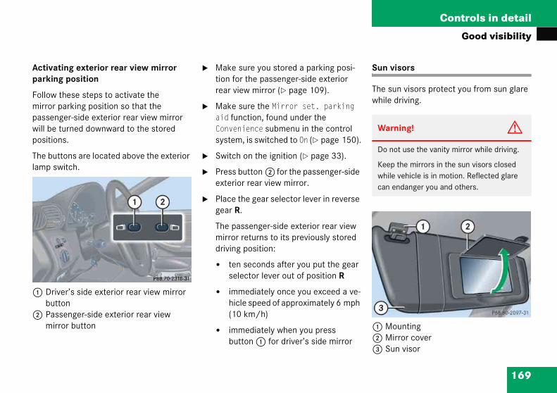
169
Controls in detail
Good visibility
Activaparkin
Followmirrorpassenwill bepositio
The bulamp s
1 Dribut
2 Pasmir
Sun visors
The sun visors protect you from sun glare while driving.
1 Mounting2 Mirror cover3 Sun visor
Warning! G
Do not use the vanity mirror while driving.
Keep the mirrors in the sun visors closed while vehicle is in motion. Reflected glare can endanger you and others.
ting exterior rear view mirror g position
these steps to activate the parking position so that the ger-side exterior rear view mirror
turned downward to the stored ns.
ttons are located above the exterior witch.
ver’s side exterior rear view mirror tonsenger-side exterior rear view ror button
� Make sure you stored a parking posi-tion for the passenger-side exterior rear view mirror (� page 109).
� Make sure the Mirror set. parking aid function, found under the Convenience submenu in the control system, is switched to On (� page 150).
� Switch on the ignition (� page 33).
� Press button 2 for the passenger-side exterior rear view mirror.
� Place the gear selector lever in reverse gear R.
The passenger-side exterior rear view mirror returns to its previously stored driving position:
� ten seconds after you put the gear selector lever out of position R
� immediately once you exceed a ve-hicle speed of approximately 6 mph (10 km/h)
� immediately when you press button 1 for driver’s side mirror

170
Controls in detail
Good v
� Swinrienc
� To u
eactivating
Press button F or 1 in the climate control panel (� page 173) or automatic climate again.
The indicator lamp on the button goes out.
iIf sunwindmou
Warning! G
Any accumulation of snow and ice should be removed from the rear window before driv-ing. Visibility could otherwise be impaired, endangering you and others.
isibility
g sun visors down when you expe-e glare.
se mirror, lift up mirror cover 2.
Rear window defroster
The rear window defroster uses a large amount of power. To keep the battery drain to a minimum, switch off the defrost-er as soon as the rear window is clear. The defroster is automatically deactivated after approximately 6 to 17 minutes of operation depending on the outside tem-perature.
Activating
� Press button F or 1 in the climate control panel (� page 173) or automatic climate.
The indicator lamp on the button comes on.
D
�
light enters through a side ow, disengage sun visor from nting 1 and pivot to the side.

171
Controls in detail
Good visibility
!If thoff stamaingcieresthe
As voltaut
e rear window defroster switches too soon and the indicator lamp rts flashing, this means that too ny electrical consumers are operat- simultaneously and there is insuffi-nt voltage in the battery. The system ponds automatically by deactivating rear window defroster.
soon as the battery has sufficient age, the rear window defroster omatically turns itself back on.

Controls in detail
t
172
Clima
e control
173
Controls in detail
Climate control
I
1 L
2 L
3 Tf
4 Tf
5 L
6 R
7 Tf
8 Tf
9 R
a R
b C
iForslidand
Item
1 Air volume control
2 Left side temperature control
3 Right side temperature control
4 Air distribution control
5 Rear window defroster
6 AC cooling on/off (ACOFF or A/C)
7 Air distribution and air volume (automatic mode)
8 Air recirculation
9 Defrosting
Depending on production date, your vehicle is equipped with either climate control panel design A or B.
Climate control panel design A
Climate control panel design B
tem
eft side defroster vent, fixed
eft side air vent, adjustable
humbwheel for air volume control or left side air vent
humbwheel for air volume control or left center air vent
eft center air vent, adjustable
ight center air vent, adjustable
humbwheel for air volume control or right center air vent
humbwheel for air volume control or right side air vent
ight side air vent, adjustable
ight side defroster vent, fixed
limate control panel
draft-free ventilation, move the ers for the air vents 2, 5, 6, 9 to the middle position.

174
Controls in detail
Climat
The climever theate the cautomatcools orthe selecurrent
Warni
When othat enthroughvery hotemperbite on area of distancbody anchangecontrolwell air
iSevere conditions (e.g. strong air pollution) may require replacement of the filter before its scheduled interval. A clogged filter will reduce the air volume to the interior.
If the vehicle interior is hot, ventilate the interior before driving off, see “Opening (Summer opening feature)” (� page 240).
Keep the air intake grille in front of the windshield free of snow and debris.
Do not obstruct air flow by placing objects on the air flow-through exhaust slots below the rear window.
e control
ate control is operational when- engine is running. You can oper-limate control system in either the ic or manual mode. The system heats the interior depending on cted interior temperature and the outside temperature.
Nearly all dust particles, pollutants and odors are filtered out before outside air en-ters the passenger compartment through the air distribution system.
The air conditioning will not engage (no cooling) if the mode ACOFF is activated or mode A/C is deactivated (� page 179).
ng! G
perating the climate control, the air ters the passenger compartment the air vents in the footwell can be t or very cold (depending on the set ature). This may cause burns or frost-unprotected skin in the immediate the air vents. Always keep sufficient e between unprotected parts of the d the footwell air vents. If necessary, the air flow using the air distribution s to direct the air away from the foot- vents (� page 176).
Warning! G
Follow the recommended settings for heat-ing and cooling given on the following pag-es. Otherwise the windows could fog up, impairing visibility and endangering you and others.
175
Controls in detail
Climate control
Deactisystem
Deacti
� Setto p
Reacti
� Setto a
Increasing
� Turn temperature control 2 or 3 slightly to the right.
The climate control system will corre-spondingly adjust the interior air tem-perature.
Decreasing
� Turn temperature control 2 or 3 slightly counterclockwise.
The climate control system will corre-spondingly adjust the interior air tem-perature.
iWhoff,tionthisthe
vating the climate control
vating
air volume control 1 (� page 173) osition 0.
vating
air volume control 1 (� page 173) ny speed.
Setting the temperature
Use temperature controls 2 and 3 (� page 173) to separately adjust the air temperature on each side of the passenger compartment. You should raise or lower the temperature setting in small incre-ments, preferably starting at 72°F (22°C).
en the air conditioning is switched the outside air supply and circula- are also switched off. Only choose setting for a short time. Otherwise windows could fog up.
iWhen operating the climate control system in automatic mode, you will only rarely need to adjust the tempera-ture, air volume and air distribution.
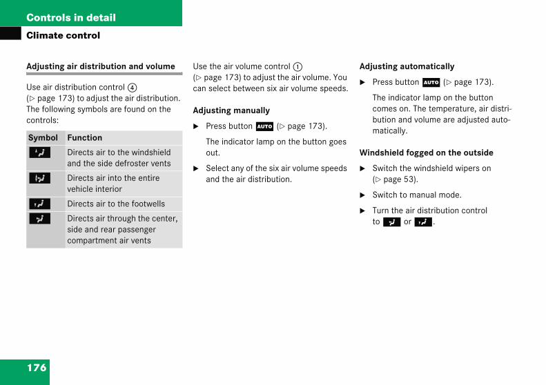
176
Controls in detail
Climat
Adjustin
Use air d(� pageThe follocontrols
djusting automatically
Press button U (� page 173).
The indicator lamp on the button comes on. The temperature, air distri-bution and volume are adjusted auto-matically.
indshield fogged on the outside
Switch the windshield wipers on (� page 53).
Switch to manual mode.
Turn the air distribution control to a or Y.
Symbo
Z
b
Y
a
e control
g air distribution and volume
istribution control 4 173) to adjust the air distribution. wing symbols are found on the :
Use the air volume control 1 (� page 173) to adjust the air volume. You can select between six air volume speeds.
Adjusting manually
� Press button U (� page 173).
The indicator lamp on the button goes out.
� Select any of the six air volume speeds and the air distribution.
A
�
W
�
�
�
l Function
Directs air to the windshield and the side defroster vents
Directs air into the entire vehicle interior
Directs air to the footwells
Directs air through the center, side and rear passenger compartment air vents
177
Controls in detail
Climate control
Defros
Activa
� Pre(�
Thecom
The airly to th
�
�
�
Activating
� Press button , (� page 173).
The indicator lamp on the button comes on.
iThefor
iIf you keep button , pressed the side windows and panorama roof with power tilt/sliding panel* will close.
Warning! G
Never operate the side windows and the panorama roof with power tilt/sliding pan-el* if there is the possibility of anyone being harmed by the closing procedure.
Vehicles without panorama roof with power tilt/sliding panel*:In the event that the procedure causes potential danger, the opening and closing of the side windows can be immediately halted by pressing or pulling the respective window switch. ��
ting
ting
ss button P or 0 page 173).
indicator lamp on the button es on.
conditioning switches automatical-e following functions:
maximum blowing and heating power
air flows onto the windshield and the front side windows
the air recirculation mode is switched off
Deactivating
� Press button P or 0 (� page 173).
The indicator lamp on the button goes out. Defrosting is turned off.
Air recirculation mode
Switch to air recirculation mode to prevent unpleasant odors from entering the vehicle from the outside. This setting cuts off the intake of outside air and recirculates the air in the passenger compartment.
se settings should only be selected a short time.
Warning! G
When the outside temperature is below 41°F (5°C), only switch to air recirculation mode for short periods to prevent window fogging.
Window fogging may impair visibility and endanger you and others.

178
Controls in detail
Climat
eactivating
Press button , (� page 173).
The indicator lamp on the button goes out.
he air recirculation mode is deactivated utomatically:
after five minutes if the outside temperature is below approximately 41°F (5°C)
after five minutes if the air conditioning is turned off
after 30 minutes if the outside temperature is above approximately 41°F (5°C)
Vehicletilt/slidIn the etential dthe sideby releaor pullinopeningwith podiately or by mtilt/slidcontrol
iIf you keep button , pressed, the side windows and panorama roof with power tilt/sliding panel* will return to their previous position.
��
e control
D
�
Ta
�
�
�
s with panorama roof with power ing panel*:vent that the procedure causes po-anger, the opening and closing of windows can be immediately halted sing the , button or by pressing g the respective window switch. The and closing of the panorama roof wer tilt/sliding panel* can be imme-halted by releasing the , button oving the panorama roof with power ing panel switch in the overhead panel in any direction.
iThe air recirculation mode is activated automatically at high outside tempera-tures.
The indicator lamp on the , button is not lit when the air recirculation mode is automatically switched on.
After approximately 30 minutes, out-side air is added to the air inside the vehicle.
If you have turned off the air condi-tioning (� page 179) or the outside temperature is below 41°F (5°C), the air recirculation mode will not switch on automatically.

179
Controls in detail
Climate control
At outs(26°C)switchoutside30 min
Air con
The airthe engair to t
Activating
Moist air can fog up the windows. You can dehumidify the air with the air condition-ing.
Climate control panel design A
� Press button ± (� page 173).
The indicator lamp on the button goes out.
Climate control panel design B
� Press button 2 (� page 173).
The indicator lamp on the button comes on.
The air conditioning uses the refrigerant R134a. This refrigerant is free of CFCs which are harmful to the ozone layer.
iConneanot
Warn
If youcle witions more obsercould
ide temperatures above 79°F the system will not automatically back to outside air. A quantity of air is added after approximately utes.
ditioning
conditioning is operational while ine is running and cools the interior
he temperature set by the operator.
Deactivating
It is possible to deactivate the air condi-tioning (cooling) function of the climate control system. The air in the vehicle will then no longer be cooled or dehumidified.
Climate control panel design A
� Press button ± (� page 173).
The indicator lamp on the button comes on.
The cooling function switches off after a short delay.
Climate control panel design B
� Press button 2 (� page 173).
The indicator lamp on the button goes out.
The cooling function switches off after a short delay.
densation may drip out from under-th the vehicle. This is normal and an indication of a malfunction.
ing! G
turn off the cooling function, the vehi-ll not be cooled when weather condi-are warm. The windows can fog up quickly. As a result, you can no longer ve traffic situations around you and cause an accident.
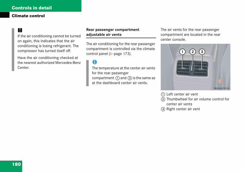
180
Controls in detail
Climat
he air vents for the rear passenger ompartment are located in the rear enter console.
Left center air ventThumbwheel for air volume control for center air ventsRight center air vent
!If theon agcondcom
Havethe nCent
e control
Rear passenger compartment adjustable air vents
The air conditioning for the rear passenger compartment is controlled via the climate control panel (� page 173).
Tcc
12
3
air conditioning cannot be turned ain, this indicates that the air itioning is losing refrigerant. The pressor has turned itself off.
the air conditioning checked at earest authorized Mercedes-Benz er.
iThe temperature at the center air vents for the rear passenger compartment 1 and 3 is the same as at the dashboard center air vents.

181
Controls in detail
Climate control
Adjust
� Pusvenleft
Thespo
iForslid
ing air distribution
h the slide for the left center t 1 or right center vent 3 to the , right, up or down.
air flow is directed in the corre-nding direction.
Adjusting air volume
� Turn thumbwheel 2 up or down.
The air volume is increased or decreased.
draft-free ventilation, push es 1 and 3 upward.

Controls in detail
182
Autom
atic climate control*
183
Controls in detail
Automatic climate control*
I
1 L
2 L
3 Tf
4 Tf
5 L
6 R
7 Tf
8 Tf
9 R
a R
b A
iForslidand
Item
1 Left side air distribution control
2 Defrosting
3 Temperature control, left, raising
4 Display
5 Air volume control, raising
6 Temperature control, right, raising
7 Rear window defroster
8 Right side air distribution control
9 Charcoal filter
a AC cooling on/off (ACOFF or A/C)
Residual heat/ventilation
b Temperature control, right, lowering
c Air volume control, lowering
d Temperature control, left, lowering
e Air recirculation
f Automatic climate control on/off (complete system)
g Air distribution and air volume (automatic mode)
Depending on production date, your vehicle is equipped with either automatic climate control panel design A or B.
Automatic climate control panel design A
Automatic climate control panel design B
tem
eft side defroster vent, fixed
eft side air vent, adjustable
humbwheel for air volume control or left side air vent
humbwheel for air volume control or left center air vent
eft center air vent, adjustable
ight center air vent, adjustable
humbwheel for air volume control or right center air vent
humbwheel for air volume control or right side air vent
ight side air vent, adjustable
ight side defroster vent, fixed
utomatic climate control panel
draft-free ventilation, move the ers for the air vents 2, 5, 6, 9 to the middle position.
184
Controls in detail
Autom
The autoal wheneoperate ther thesystem cing on thand the
iFeatnaryThe abe avall m
Warning! G
Follow the recommended settings for heating and cooling given on the following pages. Otherwise the windows could fog up, impairing visibility and endangering you and others.
iSevere conditions (e.g. strong air pollution) may require replacement of the filter before its scheduled interval. A clogged filter will reduce the air volume to the interior.
If the vehicle interior is hot, ventilate the interior before driving off, see “Opening (Summer opening feature)” (� page 245).
Keep the air intake grille in front of the windshield free of snow and debris.
Do not obstruct air flow by placing objects on the air flow-through exhaust slots below the rear window.
atic climate control*
matic climate control is operation-ver the engine is running. You can the climate control system in ei- automatic or manual mode. The ools or heats the interior depend-e selected interior temperature current outside temperature.
Nearly all dust particles, pollutants and odors are filtered out before outside air enters the passenger compartment through the air distribution system.
The air conditioning will not engage (no cooling) if the mode ACOFF is activated or mode A/C is deactivated (� page 192).
ure availability is based on prelimi- information at time of printing. utomatic climate control may not ailable as optional equipment on odels.
Warning G
When operating the automatic climate control, the air that enters the passenger compartment through the air vents in the footwell can be very hot or very cold (depending on the set temperature). This may cause burns or frostbite on unprotected skin in the immediate area of the air vents. Always keep sufficient distance between unprotected parts of the body and the foot-well air vents. If necessary change the air flow using the air distribution controls to direct the air away from the footwell air vents (� page 186).
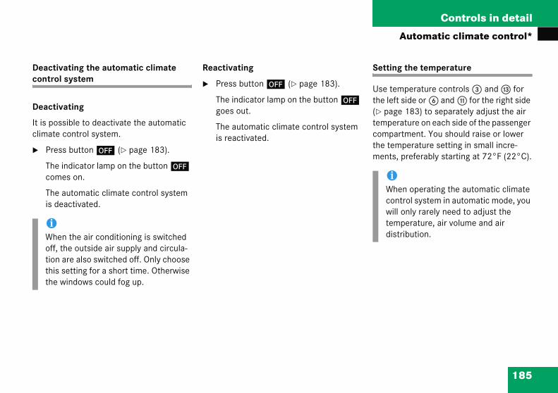
185
Controls in detail
Automatic climate control*
Deacticontro
Deacti
It is poclimate
� Pre
Thecom
Theis d
Setting the temperature
Use temperature controls 3 and d for the left side or 6 and b for the right side (� page 183) to separately adjust the air temperature on each side of the passenger compartment. You should raise or lower the temperature setting in small incre-ments, preferably starting at 72°F (22°C).
iWhoff,tionthisthe
iWhen operating the automatic climate control system in automatic mode, you will only rarely need to adjust the temperature, air volume and air distribution.
vating the automatic climate l system
vating
ssible to deactivate the automatic control system.
ss button ´ (� page 183).
indicator lamp on the button ´ es on.
automatic climate control system eactivated.
Reactivating
� Press button ´ (� page 183).
The indicator lamp on the button ´ goes out.
The automatic climate control system is reactivated.
en the air conditioning is switched the outside air supply and circula- are also switched off. Only choose setting for a short time. Otherwise windows could fog up.

186
Controls in detail
Autom
Display
1 Tem2 Blow3 Tem
Increas
� Pushand/
The awill cair te
Decreas
� Pushand/
The awill cair te
djusting manually
Turn air distribution control 1 or 8 (� page 183) to the desired symbol.
The indicator lamp on the button U goes out.
The automatic air distribution is switched off. The air distribution is controlled according to the selected control setting.
djusting automatically
Press button U (� page 183).
The indicator lamp on the button comes on.
The air volume is controlled automati-cally for the entire vehicle, and the air distribution is controlled automatically for each separate half of the vehicle.
atic climate control*
perature, lefter speedperature, right
ing
temperature control 3 or 6 (� page 183).
utomatic climate control system orrespondingly adjust the interior mperature.
ing
temperature control b or d (� page 183).
utomatic climate control system orrespondingly adjust the interior mperature.
Adjusting air distribution
Use the button U for automatic mode or air distribution controls 1 and 8 (� page 183) to separately adjust the air distribution on each side of the passenger compartment. The following symbols are found on the controls:
A
�
A
�
Symbol Function
Z Directs air to the windshield and the side defroster vents
b Directs air into the entire vehicle interior
Y Directs air to the footwells
a Directs air through the center, side and rear passenger compartment air vents
187
Controls in detail
Automatic climate control*
Winds
� Sw(�
� Sw
� Turto a
Adjusting automatically
� Press button U (� page 183).
The indicator lamp on the button comes on.
The air volume is controlled automati-cally for the entire vehicle, and the air distribution is controlled automatically for each separate half of the vehicle.
hield fogged on the outside
itch the windshield wipers on page 53).
itch to manual mode.
n air distribution control 1 or 8 or Y (� page 183).
Adjusting air volume
Use button U for automatic mode or air volume controls � or Q (� page 183) to adjust air volume manually.
Adjusting manually
Seven blower speeds are available.
� Press air volume control � or Q (� page 183) until the requested blower speed is attained.
The indicator lamp on the button U goes out.
The automatic air distribution remains switched on.

188
Controls in detail
Autom
Defrost
Activati
� Pres(� pa
The icom
The air cautomat
� mp
� at
� ts
aximum cooling MAXCOOL
the left and right air distribution controls s well as the airflow volume control are et to U (� page 183) and there is a igh need for cooling, the display MAXCOOL” appears.
his provides the fastest possible cooling f the vehicle interior (when side windows nd panorama roof with power tilt/sliding anel* are closed).
iThesfor a
atic climate control*
ing
ng
s button P or 0 ge 183).
ndicator lamp on the button es on.
onditioning switches ically to the following functions:
aximum blowing and heating ower
ir flows onto the windshield and he front side windows
he air recirculation mode is witched off
Deactivating
� Press button P or 0 (� page 183).
The indicator lamp on the button goes out. Defrosting is turned off.
The previous settings are once again in effect.
M
Ifash“
Toap
e settings should only be selected short time.

189
Controls in detail
Automatic climate control*
Air rec
Switchunpleafrom thintake air in t
Activa
� Pre
Thecom
Warn
Whenbelowrecircpreve
Windoendan
by pressing or pulling the respective window switch. The opening and closing of the pan-orama roof with power tilt/sliding panel* can be immediately halted by releasing the , button or by moving the panorama roof with power tilt/sliding panel switch in the overhead control panel in any direction.
irculation mode
to air recirculation mode to prevent sant odors from entering the vehicle e outside. This setting cuts off the of outside air and recirculates the he passenger compartment.
ting
ss button , (� page 183).
indicator lamp on the button es on.
ing! G
the outside temperature is 41°F (5°C), only switch to air
ulation mode for short periods to nt window fogging.
w fogging may impair visibility and ger you and others.
iIf you keep button , pressed, the side windows and panorama roof with power tilt/sliding panel* will close.
Warning! G
Never operate the side windows and the panorama roof with power tilt/sliding pan-el* if there is the possibility of anyone being harmed by the closing procedure.
Vehicles without panorama roof with power tilt/sliding panel*:In the event that the procedure causes potential danger, the opening and closing of the side windows can be immediately halted by pressing or pulling the respective window switch.
Vehicles with panorama roof with power tilt/sliding panel*:In the event that the procedure causes po-tential danger, the opening and closing of the side windows can be immediately halted by releasing the , button or

190
Controls in detail
Autom
he air recirculation mode is deactivated utomatically:
after five minutes if the outside temperature is below approximately 41°F (5°C)
after five minutes if the air conditioning is turned off
after 30 minutes if the outside temperature is above approximately 41°F (5°C)
t outside temperatures above 79°F 6°C) the system will not automatically
witch back to outside air. A quantity of utside air is added after approximately 0 minutes.
iThe aauto
� a
� ifooinam
The iis nomod
Afterside vehic
If youcondside the aswitc
atic climate control*
Deactivating
� Press button , (� page 183).
The indicator lamp on the button goes out.
Ta
�
�
�
A(2so3
ir recirculation mode is activated matically:
t high outside temperatures
the concentration of carbon mon-xide and nitrogen oxide in the utside air increases, for example a tunnel (charcoal filter must be
ctivated for the air recirculation ode to be activated automatically)
ndicator lamp on the button , t lit when the air recirculation e is automatically switched on.
approximately 30 minutes, out-air is added to the air inside the le.
have turned off the air itioning (� page 192) or the out-temperature is below 41°F (5°C), ir recirculation mode will not h on automatically.
iIf you keep button , pressed, the side windows and panorama roof with power tilt/sliding panel* will return to their previous position.

191
Controls in detail
Automatic climate control*
Charco
An actreducefrom ament. or dea
The syair reci
� car
or
� nitr
concenbeyond
iThedoeis abutis dbutoutbel
Vehicles without panorama roof with power tilt/sliding panel*:In the event that the procedure causes potential danger, the opening and closing of the side windows can be immediately halted by pressing or pulling the respective window switch.
Vehicles with panorama roof with power tilt/sliding panel*:In the event that the procedure causes po-tential danger, the opening and closing of the side windows can be immediately halted by releasing the e button or by pressing or pulling the respective window switch. The opening and closing of the panorama roof with power tilt/sliding panel* can be imme-diately halted by releasing the e button or by moving the panorama roof with power tilt/sliding panel switch in the overhead control panel in any direction.
al filter
ivated charcoal filter markedly s bad odors and removes pollutants ir entering the passenger compart-The charcoal filter can be activated ctivated.
stem switches automatically to the rculation mode, if the
bon monoxide (CO)
ogen oxide (NOX)
tration of the outside air increases a predetermined level.
Activating
� Press button e (� page 183).
The indicator lamp on the button comes on.
automatic air recirculation mode s not function if the ACOFF mode ctivated (indicator lamp on ton ° illuminated) or A/C mode eactivated (indicator lamp on ton 2 not lit), or if the side temperature has fallen ow 41°F (5°C).
iIf you keep button e pressed, the side windows and panorama roof with power tilt/sliding panel* will close.
iThe activated charcoal filter should be switched off when windows fog up on the inside, or if the passenger compart-ment needs to be quickly heated or cooled down.
Warning! G
Never operate the side windows and the panorama roof with power tilt/sliding pan-el* if there is the possibility of anyone being harmed by the closing procedure.
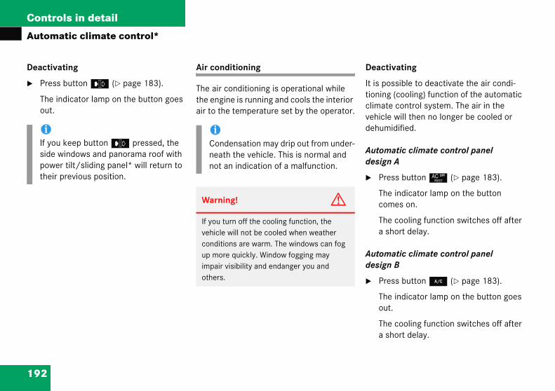
192
Controls in detail
Autom
Deactiv
� Pres
The iout.
eactivating
is possible to deactivate the air condi-oning (cooling) function of the automatic limate control system. The air in the ehicle will then no longer be cooled or ehumidified.
utomatic climate control panel esign A
Press button ° (� page 183).
The indicator lamp on the button comes on.
The cooling function switches off after a short delay.
utomatic climate control panel esign B
Press button 2 (� page 183).
The indicator lamp on the button goes out.
The cooling function switches off after a short delay.
iIf youside powetheir
atic climate control*
ating
s button e (� page 183).
ndicator lamp on the button goes
Air conditioning
The air conditioning is operational while the engine is running and cools the interior air to the temperature set by the operator.
D
Itticvd
Ad
�
Ad
�
keep button e pressed, the windows and panorama roof with r tilt/sliding panel* will return to
previous position.
iCondensation may drip out from under-neath the vehicle. This is normal and not an indication of a malfunction.
Warning! G
If you turn off the cooling function, the vehicle will not be cooled when weather conditions are warm. The windows can fog up more quickly. Window fogging may impair visibility and endanger you and others.

193
Controls in detail
Automatic climate control*
Activa
Moist adehumtioning
Automdesign
� Pre
Theout
The
Automdesign
� Pre
Thecom
The
The airR134awhich
Deactivating
� Press button ° (� page 183).
The indicator lamp on the button goes out.
The residual heat is automatically turned off:
� when the ignition is switched on
� after about 30 minutes
� if the battery voltage drops
iHow long the system will provide heating depends on
� the coolant temperature
� the temperature set by the operator
The blower will run at speed setting 1 regardless of the air distribution control setting.
ting
ir can fog up the windows. You can idify the air with the air condi-.
atic climate control panel A
ss button ° (� page 183) again.
indicator lamp on the button goes .
cooling function is switched on.
atic climate control panel B
ss button 2 (� page 183) again.
indicator lamp on the button es on.
cooling function is switched on.
conditioning uses the refrigerant . This refrigerant is free of CFCs are harmful to the ozone layer.
Residual heat and ventilation (available on automatic climate control panel design A only)
With the engine switched off, it is possible to continue to heat or ventilate the interior for up to 30 minutes. This feature makes use of the residual heat produced by the engine.
Activating
� Switch off the ignition (� page 58).
� Press button ° (� page 183).
The indicator lamp on the button comes on.
!If the air conditioning cannot be turned on again, this indicates that the air conditioning is losing refrigerant. The compressor has turned itself off.
Have the air conditioning checked at the nearest authorized Mercedes-Benz Center.

194
Controls in detail
Autom
Rear paadjusta
The air ccompartmatic cl
The air vcompartcenter c
djusting air distribution
Push the slide for the left center vent 1 or right center vent 3 to the left, right, up, or down.
The air flow is directed in the corresponding direction.
djusting air volume
Turn thumbwheel 2 up or down.
The air volume is increased or decreased.
iThe tfor thcomat th
iFor draft-free ventilation, push slides 1 and 3 upward.
atic climate control*
ssenger compartment ble air vents
onditioning for the rear passenger ment is controlled via the auto-imate control panel (� page 183).
ents for the rear passenger ment are located in the rear onsole.
1 Left center air vent2 Thumbwheel for air volume control for
center air vents3 Right center air vent
A
�
A
�
emperature at the center air vents e rear passenger
partment 1 and 3 is the same as e dashboard center air vents.
195
Controls in detail
Audio system
�Au
ThyoMetaiof
W
Inlessaao
B(in1
Audiodio an
ese insu becomrcedesn usefuthe use
arning
order tad to an
ystem still and ond traffittentionperating
ear in mapproximg a dist4 m) ev
systemd telephone, operation
tructions are intended to help e familiar with your
-Benz audio system. They con-l tips and a detailed description r functions.
Operating safety
! G
o avoid distraction which could accident, the driver should enter
ettings with the vehicle at a stand-perate the system only when road
c conditions permit. Always pay full to traffic conditions first before system controls while driving.
ind that at a speed of just 30 mph ately 50 km/h), your car is cover-
ance of 44 feet (approximately ery second.
Warning! G
Any alterations made to electronic compo-nents can cause malfunctions.
The radio, amplifier, CD changer*, satellite radio* and telephone* are interconnected. When one of the components is not opera-tional or has not been removed/replaced properly, the function of other components may be impaired.
This condition might seriously impair the operating safety of your vehicle.
We recommend that you have any service work on electronic components carried out by an authorized Mercedes-Benz Center.

196
Controls in detail
Audio
Operati
system
ng and display elements
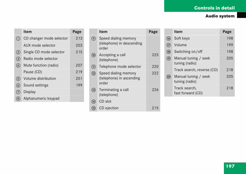
197
Controls in detail
Audio system
It
1 C
A
2 S
3 R
4 M
P
5 V
6 S
7 D
8 A
Item Page
g Soft keys 198
h Volume 199
j Switching on/off 198
k Manual tuning / seek tuning (radio)
205
Track search, reverse (CD) 218
l Manual tuning / seek tuning (radio)
205
Track search,fast forward (CD)
218
em Page
D changer mode selector
UX mode selector
213
203
ingle CD mode selector 215
adio mode selector
ute function (radio) 207
ause (CD) 219
olume distribution 201
ound settings 199
isplay
lphanumeric keypad
Item Page
9 Speed dialing memory (telephone) in descending order
a Accepting a call(telephone)
225
b Telephone mode selector 220
c Speed dialing memory (telephone) in ascending order
222
d Terminating a call(telephone)
226
e CD slot
f CD ejection 215

198
Controls in detail
Audio
Button
In thesekeypad functionare referbelow th“soft ke
!Do nface.dam
iIf the radio is switched on without the key in the starter switch, it will auto-matically switch off again after approximately 30 minutes.
If your vehicle is equipped with a tele-phone, the display may prompt you to enter your PIN (GSM network) or code (TDMA or CDMA network).
system
and soft key operation
instructions, the alphanumeric (right side of radio panel) and the buttons (left side of radio panel) red to as “buttons”. The four keys e display panel are referred to as
ys”.
Operation
Switching the unit on/off
Switching on
� Turn the SmartKey in the starter switch to position 1 or 2.
� If the audio system was on as you re-moved the SmartKey from the starter switch, the audio system will automati-cally come back on as you turn the SmartKey to position 1 or 2.
or
� Press M button.
ot press directly in the display Otherwise, the display will be aged.

199
Controls in detail
Audio system
Switch
� Rem
or
� Pre
Adjust
� Tur
Thedep
� Press + or – soft key to increase or decrease tone level accordingly.
or
� Press RES soft key briefly to reset bass tones to their center level.
The radio switches back to the stan-dard radio menu eight seconds after the last soft key is pressed.
iShooccopeperwillthefor
ing off
ove SmartKey from starter switch.
ss M button.
ing the volume
n rotary control of N button.
volume will increase or decrease ending on the direction turned.
Adjusting sound functions
The bass and treble functions are called up by pressing the O button.
Settings for bass and treble are stored sep-arately for the AM and FM wavebands, weather band, CD mode and telephone mode.
Bass
� Press O button repeatedly until BASS appears in the display.
uld excessively high temperatures ur while the audio system is being rated, the display will dim. If tem-atures continue to rise, HIGH TEMP appear in the display, after which audio system will be switched off a cooling-down period.
iIf your vehicle equipment includes a Mercedes-Benz specified mobile tele-phone*, you can adjust its volume sep-arately from the volume of the audio system while the telephone is being used.
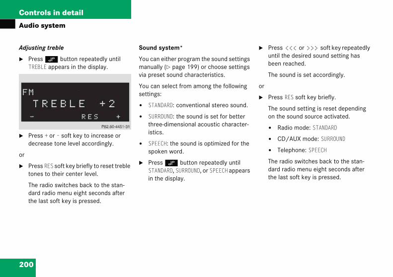
200
Controls in detail
Audio
Adjustin
� PresTREB
� Presdecr
or
� Prestone
The rdardthe l
Press X or Y soft key repeatedly until the desired sound setting has been reached.
The sound is set accordingly.
r
Press RES soft key briefly.
The sound setting is reset depending on the sound source activated.
� Radio mode: STANDARD
� CD/AUX mode: SURROUND
� Telephone: SPEECH
The radio switches back to the stan-dard radio menu eight seconds after the last soft key is pressed.
system
g treble
s O button repeatedly until LE appears in the display.
s + or – soft key to increase or ease tone level accordingly.
s RES soft key briefly to reset treble s to their center level.
adio switches back to the stan- radio menu eight seconds after ast soft key is pressed.
Sound system*
You can either program the sound settings manually (� page 199) or choose settings via preset sound characteristics.
You can select from among the following settings:
� STANDARD: conventional stereo sound.
� SURROUND: the sound is set for better three-dimensional acoustic character-istics.
� SPEECH: the sound is optimized for the spoken word.
� Press O button repeatedly until STANDARD, SURROUND, or SPEECH appears in the display.
�
o
�

201
Controls in detail
Audio system
Returnsetting
� Preme
� Pretivelev
or
� Preapp
Thearethe
� Press V or W soft key.
The volume is distributed accordingly between the front and rear of the vehi-cle.
or
� Press RES soft key briefly.
The fader is reset to its center level.
The radio switches back to the stan-dard radio menu eight seconds after the last soft key is pressed.
ing sound functions to factory s
ss O button to call up settings nu in the display.
ss RES soft key briefly; the respec- sound function is reset to its center
el.
ss and hold RES soft key until RESET ears in the display.
sound settings for bass and treble returned to their center level and volume is set to a predefined level.
Vehicles with sound system*:
The sound setting is reset depending on the sound source activated.
� Radio mode: STANDARD
� CD/AUX mode: SURROUND
� Telephone: SPEECH
The radio switches back to the standard radio menu four seconds after the last soft key is pressed.
Adjusting volume distribution
Call up fader and balance functions by pressing the P button.
Fader
� Press P button repeatedly until FADER appears in the display.

202
Controls in detail
Audio
Adjustin
� PresBALA
� Pres
The vleft a
or
� Pres
The b
The rdardthe l
Press RES soft key briefly; the respec-tive volume distribution is reset to its center (flat) level.
r
Press and hold RES soft key until RESET appears in the display.
The volume distribution settings for fader and balance are set to their cen-ter level.
The radio switches back to the stan-dard radio menu four seconds after the last soft key is pressed.
elephone* muting
your vehicle equipment includes a ercedes-Benz specified mobile tele-
hone*, you can adjust its volume sepa-tely from the volume of the audio system hile the telephone is being used.
system
g balance
s P button repeatedly until NCE appears in the display.
s X or Y soft key.
olume is distributed between the nd right sides of the vehicle.
s RES soft key briefly.
alance is reset to its center level.
adio switches back to the stan- radio menu eight seconds after ast button is pressed.
Returning volume distribution to facto-ry settings
� Press P button to call up settings menu in the display.
�
o
�
T
IfMpraw

203
Controls in detail
Audio system
Conne(AUX)
An opttor* fosourcevehiclebased of prinMerced
You cathe souvolumeAUX in
Calling
� Preapp
Cance
� Pre
Calling up wavebands for radios without SAT
� Press FM or AM soft key to switch be-tween FM and AM.
The FM and AM wavebands are called up one after another.
or
� Press WB soft key.
The weather band menu is called up.
The waveband currently selected appears in the upper left-hand corner of the display.
cting an external audio source to the radio*
ional dealer-installed cinch-connec-r connecting an external audio may become available for your model. Feature description is on preliminary information at time ting. Contact an authorized es-Benz Center for availability.
n adjust the volume (� page 199), nd settings (� page 199) and the distribution (� page 201) for the put.
up AUX mode
ss and hold Q button until AUX ears in the display.
ling AUX mode
ss any audio source button.
Radio operation
Selecting radio mode
� Press b button.
Calling up wavebands
You can choose from among the FM, AM and WB wavebands.
Weather band (� page 207).
iFM waveband: 87.7......107.9 MHz
AM waveband: 530......1710 KHz

204
Controls in detail
Audio
Calling SAT
� Presuntillecte
The Fcalle
The wappeof th
irect frequency input
Select desired waveband.
Press * button.
Enter desired frequency with buttons 1 to R.
system
up wavebands for radios with
s FM, AM, or WB soft key repeatedly desired waveband has been se-d.
M, AM, and WB wavebands are d up one after another.
aveband currently selected ars in the upper left-hand corner e display.
Selecting a station
The following options are available for se-lecting a station:
� Direct frequency input (� page 204)
� Manual tuning (� page 205)
� Automatic seek tuning (� page 205)
� Scan search (� page 205)
� Station memory (� page 206)
� Automatic station memory (Autostore) (� page 206)
The station search proceeds in the follow-ing frequency increments:
� 200 KHz in FM range
� 10 KHz in AM range
D
�
�
�

205
Controls in detail
Audio system
Manua
� Sel
� Preapp
� Prefreq
Stein atimtunual
Scan search
� Starting scan search
� Select desired waveband.
� Press SC soft key.
SC will appear in the display. The radio briefly tunes in all receivable stations on the waveband selected.
iYouthe
If afouthe
l tuning
ect desired waveband.
ss S or T button for roximately three seconds.
ss button repeatedly until desired uency has been reached.
p-by-step station tuning takes place scending or descending order. Each e the button is pressed, the radio es further by 0.2 MHz. During man- tuning, the radio is muted.
Automatic seek tuning
� Select desired waveband.
� Press S or T button briefly.
The radio will tune to the next highest or next lowest receivable frequency.
can only enter frequencies within respective waveband.
button is not pressed within r seconds, the radio will return to last station tuned.
iIf no station is received after two consecutive scans of the complete frequency range, then the scan stops at the frequency from which it began.

206
Controls in detail
Audio
� Endi
� P
Tled
Station
You canin the m
� Stori
� T
Calling up Autostore memory level and storing stations
� Press AS soft key briefly.
The radio switches to the Autostore memory level. AS and SEARCH ap-pear in the display and the radio finds the ten stations with the strongest signals. These stations are stored on the station buttons 1 to R in order of signal strength.
system
ng scan search
ress SC soft key or S or T.
he station last played will be se-cted and SC disappears from the isplay.
memory
store ten AM and ten FM stations emory.
ng stations
une in desired station.
� Press and hold desired station button 1 to R until a brief signal tone is heard.
The frequency is stored on the se-lected station button.
� Calling up stations
� Press desired station button 1 to R briefly.
Autostore – automatic station memory
The Autostore memory function provides an additional memory level. The station memory for manually stored stations is not overwritten.
�
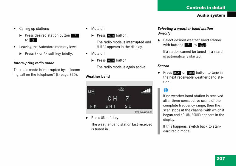
207
Controls in detail
Audio system
� Cal
�
� Lea
�
Interru
The rading cal
Selecting a weather band station directly
� Select desired weather band station with buttons 1 to 7.
If a station cannot be tuned in, a search is automatically started.
Search
� Press S or T button to tune in the next receivable weather band sta-tion.
iIf no weather band station is received after three consecutive scans of the complete frequency range, then the scan stops at the channel with which it began and NO WB FOUND appears in the display.
If this happens, switch back to stan-dard radio mode.
ling up stations
Press desired station button 1 to R.
ving the Autostore memory level
Press FM or AM soft key briefly.
pting radio mode
io mode is interrupted by an incom-l on the telephone* (� page 225).
� Mute on
� Press U button.
The radio mode is interrupted and MUTED appears in the display.
� Mute off
� Press U button.
The radio mode is again active.
Weather band
� Press WB soft key.
The weather band station last received is tuned in.

208
Controls in detail
Audio
Scan se
� Start
� P
Sdw
� Endi
� P
Tpa
iAdditional satellite radio equipment and a subscription to a satellite radio service provider are required for the satellite radio operation described here.
Contact an authorized Mercedes-Benz Center for details and availability for your vehicle.
Note that categories and channels shown in illustrations are dependent on programming content delivered by the service provider. Programming content is subject to change. Therefore, chan-nels and categories shown in illustra-tions and descriptions contained in this manual may differ from the channels and categories delivered by the service provider.
system
arch
ing scan search
ress SC soft key.
C will appear in the display. The ra-io briefly tunes in all receivable eather band stations.
ng scan search
ress SC soft key or S or T.
he weather band station last layed will be selected and SC dis-ppears from the display.
Introduction to satellite radio* (USA only)
SIRIUS satellite radio provides 100 chan-nels of digital-quality radio, among others music, sports, news, and entertainment, free of commercials. SIRIUS satellite radio uses a fleet of high-power satellites to broadcast 24 hours per day, coast to coast, in the contiguous U.S.
This diverse, satellite-delivered programming is available for a monthly subscription fee.For more information and service availability, call the SIRIUS Service Center (� page 213), or contact www.siriusradio.com

209
Controls in detail
Audio system
Progra
The challow ya certa(� pag
� Press ESN soft key.
The twelve-digit electronic serial num-ber (ESN) of the SAT tuner* installed in your vehicle is displayed.
This information is required to call the SIRIUS Service Center for an activation request.
After activation of the satellite radio service
The satellite radio main menu appears.The radio station selected last is audible, provided it can be received.
iSatablfor ronandproalso(e.gwiter t
iCredit card information may also be re-quired for your application.
The activation process takes approxi-mately five to ten minutes after calling the SIRIUS Service Center.
m categories
annels are categorized. Categories ou to tune to stations broadcasting in type of program (category mode) e 211).
Calling up the SAT main menu
� Press SAT soft key.
SAT is displayed in the upper left-hand corner of the display.
Prior to activation of the satellite radio service (� page 209).
After activation of satellite radio ser-vice (� page 209).
Prior to activation of the satellite radio service
The telephone number of the SIRIUS Service Center (888-539-7474) is dis-played.
ellite radio service may be unavail-e or interrupted from time to time a variety of reasons, such as envi-mental or topographic conditions other things beyond the service vider’s or our control. Service might not be available in certain places ., in tunnels, parking garages, or
hin or next to buildings) or near oth-echnologies.
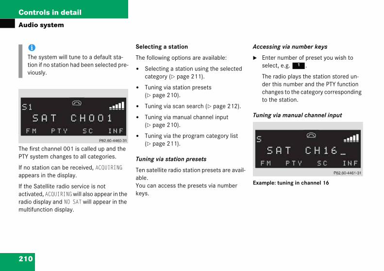
210
Controls in detail
Audio
The firstPTY syst
If no staappears
If the Saactivateradio dismultifun
ccessing via number keys
Enter number of preset you wish to select, e.g. 1.
The radio plays the station stored un-der this number and the PTY function changes to the category corresponding to the station.
uning via manual channel input
xample: tuning in channel 16
iThe stion vious
system
channel 001 is called up and the em changes to all categories.
tion can be received, ACQUIRING in the display.
tellite radio service is not d, ACQUIRING will also appear in the play and NO SAT will appear in the ction display.
Selecting a station
The following options are available:
� Selecting a station using the selected category (� page 211).
� Tuning via station presets (� page 210).
� Tuning via scan search (� page 212).
� Tuning via manual channel input (� page 210).
� Tuning via the program category list (� page 211).
Tuning via station presets
Ten satellite radio station presets are avail-able.You can access the presets via number keys.
A
�
T
E
ystem will tune to a default sta-if no station had been selected pre-ly.
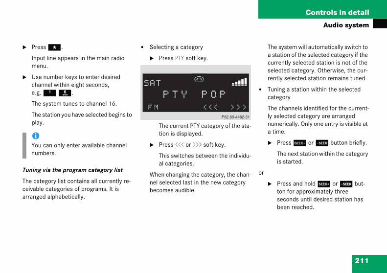
211
Controls in detail
Audio system
� Pre
Inpme
� Usechae.g
The
Thepla
Tuning
The caceivabarrang
The system will automatically switch to a station of the selected category if the currently selected station is not of the selected category. Otherwise, the cur-rently selected station remains tuned.
� Tuning a station within the selected category
The channels identified for the current-ly selected category are arranged numerically. Only one entry is visible at a time.
� Press S or T button briefly.
The next station within the category is started.
or
� Press and hold S or T but-ton for approximately three seconds until desired station has been reached.
iYounum
ss *.
ut line appears in the main radio nu.
number keys to enter desired nnel within eight seconds, . 1 6.
system tunes to channel 16.
station you have selected begins to y.
via the program category list
tegory list contains all currently re-le categories of programs. It is ed alphabetically.
� Selecting a category
� Press PTY soft key.
The current PTY category of the sta-tion is displayed.
� Press <<< or >>> soft key.
This switches between the individu-al categories.
When changing the category, the chan-nel selected last in the new category becomes audible.
can only enter available channel bers.
212
Controls in detail
Audio
Tuning v
Scan se
� Scanproxskipscurre
� Scanally.
� Pres
The sdispl
� Pres
The s
toring stations
Tune in desired station.
Press and hold desired station button 1 to R until a brief signal tone is heard.
The frequency is stored on the selected station button.
The radio saves the current station at the memory preset selected. The mem-ory preset selected appears in the sta-tus line, e.g. S3.
iThere are ten presets available.
An existing entry is overwritten in the memory list when a new entry is given.
system
ia scan search
arch is characterized as follows:
search plays a channel for ap-imately eight seconds and then to the next channel within the nt category.
search can be terminated manu-
s SC soft key.
earch starts. SC appears in the ay.
s SC soft key again.
earch stops.
Obtaining additional text information
Additional text information (artist, title) re-lated to the current channel can be dis-played.
� Press INF soft key.
The title being played is displayed.
� Press INF soft key again.
The name of the artist performing the title being played is displayed.
S
�
�
iIf a button is not pressed within four seconds, the radio will return to the standard display.
213
Controls in detail
Audio system
Calling
� Pre
� Pre
Theberyou
� Pre
General notes
The system may not be able to play audio CDs with copy protection.
Playing copied CDs may cause malfunc-tions during playback.
Warning! G
In order to avoid distraction which could lead to an accident, the driver should insert CDs with the vehicle at a standstill and oper-ate the audio system only if permitted by road, weather and traffic conditions.Bear in mind that at a speed of just 30 mph (approximately 50 km/h), your car covers a distance of 44 feet (approximately 14 m) ev-ery second.
up the ESN information menu
ss INF soft key.
ss ESN soft key.
twelve-digit electronic serial num- (ESN) of the SAT tuner* installed in r vehicle is displayed.
ss RET soft key to exit the menu.
CD mode
Safety precautions
Warning! G
The single CD player and the CD changer* are Class 1 laser products. There is a danger of invisible laser radiation if the housing is opened or damaged.Do not open the housing. The single CD player and the CD changer* do not contain any parts that can be serviced by the user. For safety reasons, have any service work which may be necessary performed only by qualified personnel.
214
Controls in detail
Audio
ips on handling CDs
Handle CDs carefully to prevent inter-ference during playback.
Avoid scratches, fingerprints and dust on the CDs.
Do not write on CDs or apply any labels or other material to them.
Clean CDs from time to time with a commercially available cleaning cloth. Never wipe the CD in a circular motion; instead, wipe it in a straight line start-ing in the center and moving outward. Do not use solvents, anti-static sprays, etc. for cleaning.
Replace the CD in its case after use.
Protect CDs from heat and direct sun-light.
!If youbecodeveer.In ceno loage tcoveWarr
!Yourdesigsponcan timum
If youonesside audiowill d
system
Do not use CDs with an eight cm diameter, not even with a CD adapter. Attempting to play CDs with an eight cm diameter or playing such CDs with an adapter may cause damage to the CD drive. Such dam-age is not covered by the Mercedes-Benz Limited Warranty.
Should excessively high or low tempera-tures occur while in CD changer mode*, CD TEMP will appear in the display, and the CD will be muted until the temperature has reached an acceptable level for the system to continue operation.
The single CD player and the CD changer* play audio CDs.
T
�
�
�
�
�
�
affix stickers to the CDs, they can me warped due to the heat that lops in the CD drive or CD chang-
rtain situations, the CDs can then nger be ejected and cause dam-o the drive. Such damage is not red by the Mercedes-Benz Limited anty.
CD drive or CD changer has been ned to play CDs which corre-d to the EN 60908 standard. You herefore only use CDs with a max- thickness of 1.3 mm.
insert thicker data carriers, e.g. that have data on both sides (one with DVD data, the other side with data), they cannot be ejected and amage the drive.
215
Controls in detail
Audio system
Operaaudio
Loadin
The sinunit hafor loadthe sof
� Ma
� Insthe
Theintoto p
Operational readiness of CD changer*
If a CD changer* has been installed in the vehicle, it can be operated from the front control panel of the audio system. A load-ed magazine must be installed to play CDs.
The CD changer is located in the glove box.
Loading/unloading the CD magazine
� Slide changer door to the right and press g button.
� Magazine will be ejected.!If aejeserothto tMe
iThe CD changer* may not be able to play audio CDs with copy protection.
ting the single CD player in the system unit
g a CD
gle CD player in the audio system s capacity for one CD. The CD slot ing the drive is located underneath
t keys.
ke sure the system is switched on.
ert CD into CD slot. The label side of CD must face upwards.
system automatically pulls the CD the CD slot. The audio CD begins lay.
Ejecting a CD
� Make sure the system is switched on.
� Press EJECT button.
The system ejects the CD. NO CD will appear in the display.
� Remove CD from slot.
CD is already loaded, it must be cted before inserting a new CD. In-ting a second CD in the slot with an-er CD still loaded will cause damage he CD drive not covered by the rcedes-Benz Limited Warranty.
iIf a CD has been inserted incorrectly or cannot be read, WRONG CD0 will appear in the display.
iIf you do not take the CD out of the CD slot within approximately 15 seconds, the system automatically pulls the CD back in and plays it.
If a CD is pulled back in, press EJECT button for five seconds; the CD will then be ejected.

216
Controls in detail
Audio
1 CD2 CD c3 CD t4 CD m
� RemCD t
� Placeup.
D changer*
Press Q button.
CD and the selected magazine slot num-ber appear in the upper left-hand cor-ner of the display.
you have not removed a CD since the last me the CD audio source was activated, e last CD listened to will begin to play at e point where it was switched off.
fter the last track on a CD has finished, e next CD is automatically played.
system
hangerrayagazine
ove magazine 4 and pull ray 3 fully out.
CD 1 in recess of tray, label side
� Push tray into magazine in direction of arrow.
� Push magazine into CD changer* 2 in direction of arrow and close sliding door.
Playing CDs
Single CD player in the audio unit
� Press i button.
CD 0 will appear in the upper left-hand corner of the display.
The CD will resume playback at the point where it was switched off.
C
�
Iftithth
Ath
iCDs which have been inserted improp-erly or are unreadable will not be played.

217
Controls in detail
Audio system
Playin
You ha
� Audlec
� Dir
� Tra
� Fas
� Sca
� Ran
� Rep
Direct track entry
You can make a direct selection from among the tracks on a CD.
� Press * button.
� Enter track number using buttons 1 to R.
iIf there is no CD in the selected maga-zine slot, NO CD appears in the display with the corresponding slot number.
��
g tracks
ve the following options:
io system with CD changer*: se-ting CDs
ect track entry
ck skip forward/reverse
t forward/reverse
n
dom tracks
eat track
Selecting CDs in the audio unit with CD changer*
� You can select from among the inserted CDs with buttons R to 6.
R = CD player in the audio unit 1 to 6 = CDs in the CD changer*
The magazine slot number of the se-lected CD appears next to CD in the dis-play, and the number of the currently played track appears next to TRACK.

218
Controls in detail
Audio
The nappe
You bers
Skippin
� Skip
� P
T
� Skip
� P
Ifmsttut
Pressingedly willskipped
can
Starting scan
� Press SC soft key.
SC will appear in the display.
Each track on the current CD will be played for approximately eight sec-onds in ascending order.
Ending scan
� Press SC soft key or T or S.
andom play
he random function (RDM) plays the acks of the current CD in random order.
iWhen you start the RDM function, the RPT function is automatically switched off.
��
system
umber of the track being played ars next to TRACK in the display.
can only enter available track num-.
g tracks forward/backward
ping tracks forward
ress S button briefly.
he next track will be played.
ping tracks backward
ress T button briefly.
the track has been playing for ore than ten seconds, the unit
kips back to the beginning of the rack currently playing. If less than en seconds have been played, the nit skips back to the beginning of he previous track.
the T or S button repeat- result in multiple tracks being .
Fast forward/reverse
� Fast forward
� Press and hold S button until desired point has been reached.
� Reverse
� Press and hold T button until desired point has been reached.
S
�
�
R
Ttr
iThe track number and the relative time of the track is shown in the display dur-ing the search.

219
Controls in detail
Audio system
� Sw
�
� Sw
�
Repea
The trarepeat
� Switching on pause function
� Press U button.
The CD changer mode is interrupt-ed and PAUSE appears in the dis-play.
� Switching off pause function
� Press U button.
The CD changer mode is active again.
iWhRDswi
itching on random
Press RDM soft key.
RDM appears in the display. A ran-domly selected track is played.
itching off random
Press RDM soft key again.
t
ck being played is repeated until the function is switched off.
� Switching on repeat
� Press RPT soft key.
RPT appears in the display.
� Switching off repeat
� Press RPT soft key again.
Pause function
The CD changer mode is interrupted by an incoming call on the telephone* (� page 225).
en you start the RPT function, the M function is automatically tched off.
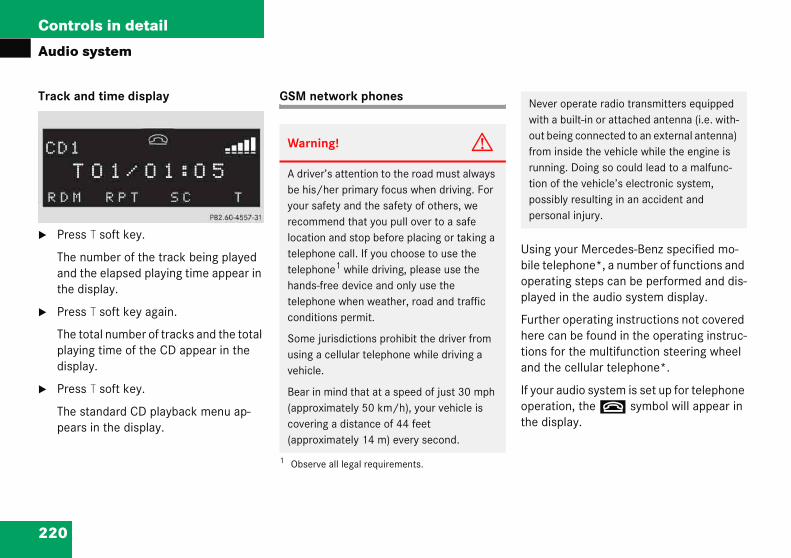
220
Controls in detail
Audio
Track a
� Pres
The nand tthe d
� Pres
The tplayidispl
� Pres
The spear
sing your Mercedes-Benz specified mo-ile telephone*, a number of functions and perating steps can be performed and dis-layed in the audio system display.
urther operating instructions not covered ere can be found in the operating instruc-ons for the multifunction steering wheel nd the cellular telephone*.
your audio system is set up for telephone peration, the t symbol will appear in e display.
Never operate radio transmitters equipped with a built-in or attached antenna (i.e. with-out being connected to an external antenna) from inside the vehicle while the engine is running. Doing so could lead to a malfunc-tion of the vehicle’s electronic system, possibly resulting in an accident and personal injury.
system
nd time display
s T soft key.
umber of the track being played he elapsed playing time appear in isplay.
s T soft key again.
otal number of tracks and the total ng time of the CD appear in the ay.
s T soft key.
tandard CD playback menu ap-s in the display.
GSM network phones
Ubop
Fhtia
Ifoth
Warning! G
A driver’s attention to the road must always be his/her primary focus when driving. For your safety and the safety of others, we recommend that you pull over to a safe location and stop before placing or taking a telephone call. If you choose to use the telephone1 while driving, please use the hands-free device and only use the telephone when weather, road and traffic conditions permit.
Some jurisdictions prohibit the driver from using a cellular telephone while driving a vehicle.
Bear in mind that at a speed of just 30 mph (approximately 50 km/h), your vehicle is covering a distance of 44 feet (approximately 14 m) every second.
1 Observe all legal requirements.
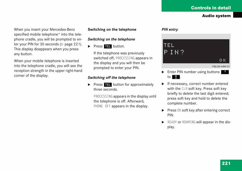
221
Controls in detail
Audio system
When yspecifiphone ter youThis diany bu
When yinto threceptcorner
PIN entry
� Enter PIN number using buttons 1 to R.
� If necessary, correct number entered with the CLR soft key. Press soft key briefly to delete the last digit entered; press soft key and hold to delete the complete number.
� Press OK soft key after entering correct PIN.
� READY or ROAMING will appear in the dis-play.
ou insert your Mercedes-Benz ed mobile telephone* into the tele-cradle, you will be prompted to en-r PIN for 30 seconds (� page 221). splay disappears when you press tton.
our mobile telephone is inserted e telephone cradle, you will see the ion strength in the upper right-hand of the display.
Switching on the telephone
Switching on the telephone
� Press h button.
If the telephone was previously switched off, PROCESSING appears in the display and you will then be prompted to enter your PIN.
Switching off the telephone
� Press h button for approximately three seconds.
PROCESSING appears in the display until the telephone is off. Afterward, PHONE OFF appears in the display.
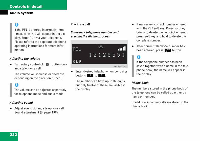
222
Controls in detail
Audio
Adjustin
� Turning a
The vdepe
Adjustin
� AdjuSoun
If necessary, correct number entered with the CLR soft key. Press soft key briefly to delete the last digit entered; press soft key and hold to delete the complete number.
After correct telephone number has been entered, press s button.
hone book
he numbers stored in the phone book of e telephone can be called up either by
ame or number.
addition, incoming calls are stored in the hone book.
iIf thetimeplay.Pleasopermati
iThe vfor te
iIf the telephone number has been saved together with a name in the tele-phone book, the name will appear in the display.
system
g the volume
rotary control of N button dur- telephone call.
olume will increase or decrease nding on the direction turned.
g sound
st sound during a telephone call. d adjustment (� page 199).
Placing a call
Entering a telephone number and starting the dialing process
� Enter desired telephone number using buttons 1 to R.
The number can have up to 32 digits, but only twelve of these are visible in the display.
�
�
P
Tthn
Inp
PIN is entered incorrectly three s, NEED PUK will appear in the dis- Enter PUK via your telephone. e refer to the separate telephone
ating instructions for more infor-on.
olume can be adjusted separately lephone mode and audio mode.
223
Controls in detail
Audio system
� Seaboo
Youphosysentpho
� Press button ‚ or ƒ repeat-edly until desired entry has been reached.
The stored entries are selected in alphabetical order with the sub-en-tries.
iThithecluingtranin t
iSeveral sub-entries can be stored for each main entry (name). These entries are marked by a corresponding abbre-viation that appears in the upper left-hand corner of the display. The fol-lowing abbreviations for sub-entries are possible:
CEL = Mobile phoneHOM = HomeWOR = WorkFAX = FaxPAG = PagerTEL = Main ��
rching and calling up telephone k entries by name
can access your mobile tele-ne’s phone book using the audio tem. You can access both the main ries and the sub-entries of your ne book.
� Press MEM soft key or press ‚ or ƒ.
� Press desired numerical key 2 to 9.
The stored entries are selected ac-cording to the alphabetical order of the initial letters (e.g. for S -Schneider, press button 7 four times).
or
� Press and hold button ‚ or ƒ.
The system jumps from one initial letter to the next in ascending or descending order.
� Press and hold button ‚ or ƒ until desired initial letter has been reached.
or
s is only possible, however, when call information transmitted in-des the number of the person call-. If the telephone number is not smitted, NO NUMBER will be stored
he phone book.
224
Controls in detail
Audio
� Wp
T
� Viewtelep
� S
� P
Tb
� Retu
Speed dial
If you have stored telephone numbers as speed dial numbers in your tele-phone, you can also enter these with buttons 1 to R on the radio head unit.
� Press desired button 1 to R briefly.
� Press s button.
The call will be made.
Turbo dial
If you have stored telephone numbers as turbo dial numbers in your tele-phone, you can also enter these with buttons 1 to R on the radio head unit.
� Press desired button 1 to R until the call is made.
��
system
hen you have selected a number, ress s button.
he call will be made.
ing the telephone number of a hone book entry
earch for desired entry.
ress NUM soft key.
he telephone number of the phone ook entry appears in the display.
rning calls received
� Press MEM soft key or press ‚ or ƒ.
� Press RCV soft key (received calls).
The number of received calls and then the call last received appear briefly in the display.
� Select desired telephone number with button ‚ or ƒ.
The letter R and the number of the memory position appear in the up-per left-hand corner of the display. The numbers are stored in the order of the calls received.
� When you have selected a number, press s button.
The call will be made.
�
�
225
Controls in detail
Audio system
Redial
If the ncan agphone functio
� Ma
Accepting an incoming call
If the telephone is active in the background (reception symbol is visible in the display), the audio source is muted when an incom-ing call is received. A ringing tone can be heard and the caller’s telephone number, or the name under which the telephone number has been saved in the phone book, appears in the display. If the caller’s num-ber is not transmitted with the call, CALL will appear in the display.
� Press s button.
The call is accepted.
iIf ydianumautwaiReftion
umber you have dialed is busy, you ain place calls to the last ten tele-numbers dialed using the redial n.
nual redial
� Press s button.
The telephone number last dialed will appear in the display.
� Select desired telephone number with button ‚ or ƒ.
The letter L and the number of the memory position appears in the left-hand corner of the display. The numbers are stored in the order of the calls received.
� When you have selected a number, press s button.
The call will be made.
ou have activated the automatic re-l function on your telephone, the
ber of the person being called is omatically redialed after a short ting period if there is a busy signal. er to the separate operating instruc-s for the mobile telephone.
226
Controls in detail
Audio
Muting
It is posthen no
� Mute
� P
� M
� Mute
� P
Termina
� Pres
The cmuteagain
You are connected with the second caller; the first caller is kept on hold.
Switching between calls
� Press 2 and s buttons.
This switches between the calls. The non-active call is kept on hold.
iYou will be notified of the second call acoustically, but you will not see this in the display.
system
a call
sible to mute a call; the caller is longer able to hear you.
on
ress MUT soft key.
IC MUTE will appear in the display.
off
ress MUT soft key again.
ting a call
s t button.
urrent call is terminated and the d audio source becomes active .
Talking with two callers at the same time
If you wish to receive or place another call during an already active call, you can ac-cept or place the second call and switch between the callers or combine them into one call. Note that the features described here are depending on availability from your mobile phone service provider.
� Placing/accepting a second call
� Place new call by entering tele-phone number manually.
� Press s button.
You are connected to the second caller; the first caller is kept on hold.
or
� Press s button to accept a sec-ond call.
�
227
Controls in detail
Audio system
� Ter
�
� Com
�
� Ter
�
Using your Mercedes-Benz specified mo-bile telephone*, a number of functions and operating steps can be performed and dis-played in the audio system display.
Further operating instructions not covered here can be found in the operating instruc-tions for the multifunction steering wheel and the mobile telephone*.
If your audio system is set up for telephone operation, the t symbol will appear in the display.
When you insert your Mercedes-Benz specified mobile telephone* into the tele-phone cradle, you will be prompted to en-
Never operate radio transmitters equipped with a built-in or attached antenna (i.e. with-out being connected to an external antenna) from inside the vehicle while the engine is running. Doing so could lead to a malfunc-tion of the vehicle’s electronic system, possibly resulting in an accident and personal injury.
minating a call
Press t button.
The current call is terminated. You are again connected with the caller previously placed on hold.
bining two calls
Press 3 and s buttons.
The calls are combined into one call.
minating a combined call
Press t button.
The connection to both callers is terminated.
TDMA or CDMA network phones
Warning! G
A driver’s attention to the road must always be his/her primary focus when driving. For your safety and the safety of others, we recommend that you pull over to a safe location and stop before placing or taking a telephone call. If you choose to use the telephone1 while driving, please use the hands-free device and only use the telephone when weather, road and traffic conditions permit.
Some jurisdictions prohibit the driver from using a cellular telephone while driving a vehicle.
Bear in mind that at a speed of just 30 mph (approximately 50 km/h), your vehicle is covering a distance of 44 feet (approximately 14 m) every second.
1 Observe all legal requirements.

228
Controls in detail
Audio
ter your This dispany butt
When yointo the receptiocorner o
Press OK soft key after entering correct code.
The telephone is unlocked. If you have entered an incorrect code, you must enter the correct code.
witching off the telephone
Press h button for approximately three seconds.
PROCESSING appears in the display until the telephone is off. Afterward, PHONE OFF appears in the display.
djusting the volume
Turn rotary control of N button dur-ing a telephone call.
The volume will increase or decrease depending on the direction turned.
iThe volume can be adjusted separately for telephone mode and audio mode.
system
PIN for 30 seconds (� page 228). lay disappears when you press
on.
ur mobile telephone is inserted telephone cradle, you will see the n strength in the upper right-hand f the display.
Switching on the telephone
Switching on the telephone
� Press h button.
If you have programmed an unlock code for the telephone, you must now enter the code.
� Enter code using buttons 1 to R.
� If necessary, correct number entered with the CLR soft key. Press soft key briefly to delete the last digit entered; press soft key and hold to delete the complete number.
�
S
�
A
�
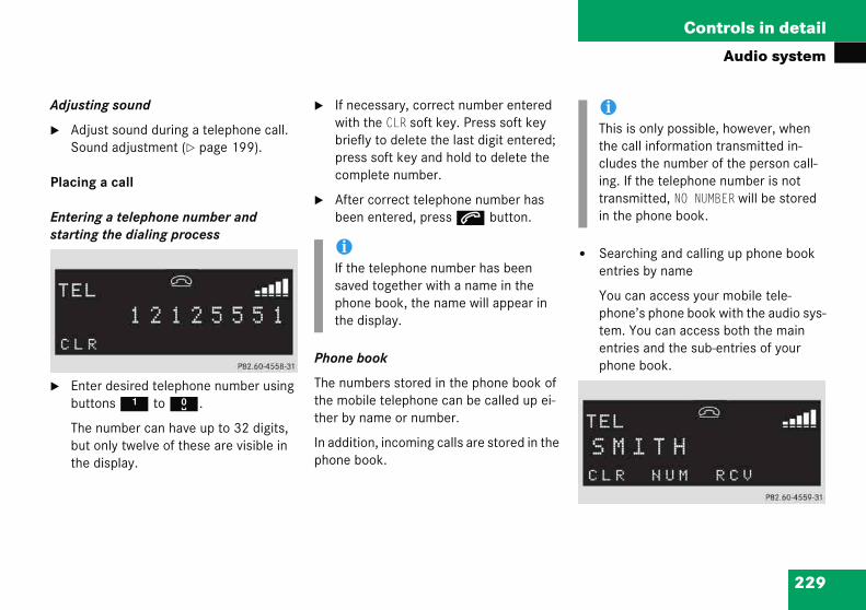
229
Controls in detail
Audio system
Adjust
� AdjSou
Placin
Enterinstartin
� Entbut
Thebutthe
� Searching and calling up phone book entries by name
You can access your mobile tele-phone’s phone book with the audio sys-tem. You can access both the main entries and the sub-entries of your phone book.
iThis is only possible, however, when the call information transmitted in-cludes the number of the person call-ing. If the telephone number is not transmitted, NO NUMBER will be stored in the phone book.
ing sound
ust sound during a telephone call. nd adjustment (� page 199).
g a call
g a telephone number and g the dialing process
er desired telephone number using tons 1 to R.
number can have up to 32 digits, only twelve of these are visible in display.
� If necessary, correct number entered with the CLR soft key. Press soft key briefly to delete the last digit entered; press soft key and hold to delete the complete number.
� After correct telephone number has been entered, press s button.
Phone book
The numbers stored in the phone book of the mobile telephone can be called up ei-ther by name or number.
In addition, incoming calls are stored in the phone book.
iIf the telephone number has been saved together with a name in the phone book, the name will appear in the display.

230
Controls in detail
Audio
� Pƒ
� Pt
TctSf
or
� Pƒ
Tled
� Pƒb
or
� When you have selected a number, press s button.
The call will be made.
Viewing the telephone number of a phone book entry
� Search for desired entry.
� Press NUM soft key.
The telephone number of the phone book entry appears in the display.
Returning calls received
system
ress MEM soft key or press ‚ or .
ress desired numerical key 2 o 9.
he stored entries are selected ac-ording to the alphabetical order of he initial letters (e.g. for -Schneider, press button 7
our times).
ress and hold button ‚ or .
he system jumps from one initial tter to the next in ascending or escending order.
ress and hold button ‚ or until desired initial letter has
een reached.
� Press button ‚ or ƒ repeat-edly until desired entry has been reached.
The stored entries are selected in alphabetical order with the sub-en-tries.
�
�
iSeveral sub-entries can be stored for each main entry (name). These entries are marked by a corresponding abbre-viation that appears in the upper left-hand corner of the display. The fol-lowing abbreviations for sub-entries are possible:
CEL = Mobile phoneHOM = HomeWOR = WorkFAX = FaxPAG = PagerTEL = Main
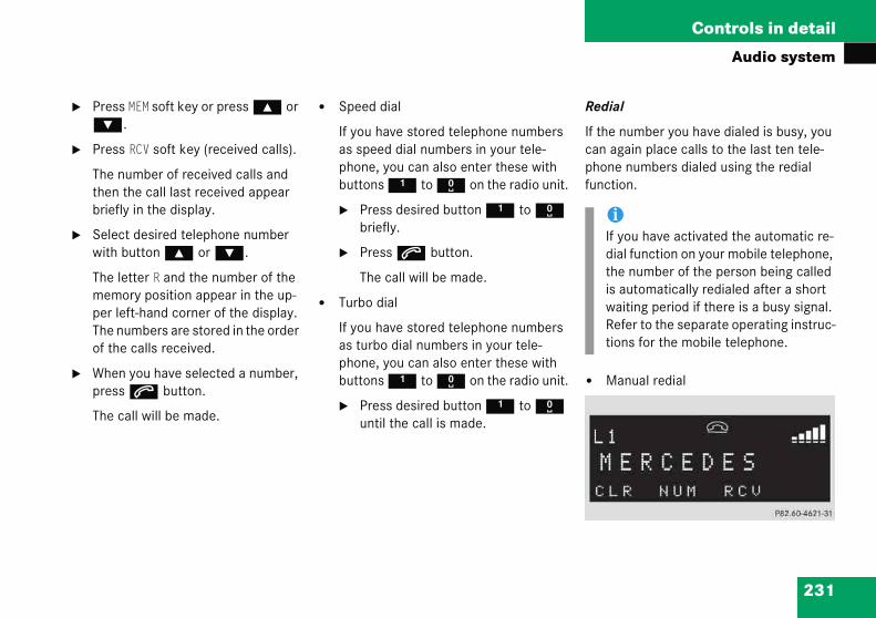
231
Controls in detail
Audio system
�
�
�
�
Redial
If the number you have dialed is busy, you can again place calls to the last ten tele-phone numbers dialed using the redial function.
� Manual redial
iIf you have activated the automatic re-dial function on your mobile telephone, the number of the person being called is automatically redialed after a short waiting period if there is a busy signal. Refer to the separate operating instruc-tions for the mobile telephone.
Press MEM soft key or press ‚ or ƒ.
Press RCV soft key (received calls).
The number of received calls and then the call last received appear briefly in the display.
Select desired telephone number with button ‚ or ƒ.
The letter R and the number of the memory position appear in the up-per left-hand corner of the display. The numbers are stored in the order of the calls received.
When you have selected a number, press s button.
The call will be made.
� Speed dial
If you have stored telephone numbers as speed dial numbers in your tele-phone, you can also enter these with buttons 1 to R on the radio unit.
� Press desired button 1 to R briefly.
� Press s button.
The call will be made.
� Turbo dial
If you have stored telephone numbers as turbo dial numbers in your tele-phone, you can also enter these with buttons 1 to R on the radio unit.
� Press desired button 1 to R until the call is made.

232
Controls in detail
Audio
� P
Tw
� Sw
Tmlent
� Wp
T
uting a call
is possible to mute a call; the caller is en no longer able to hear you.
Mute on
� Press MUT soft key.
� MIC MUTE will appear in the display.
Mute off
� Press MUT soft key again.
erminating a call
Press t button.
The current call is terminated and the muted audio source becomes active again.
system
ress s button.
he telephone number last dialed ill appear in the display.
elect desired telephone number ith button ‚ or ƒ.
he letter L and the number of the emory position appears in the ft-hand corner of the display. The umbers are stored in the order of he calls received.
hen you have selected a number, ress s button.
he call will be made.
Accepting an incoming call
If the telephone is active in the background (reception symbol is visible in the display), the audio source is muted when an incom-ing call is received. A ringing tone can be heard and the caller’s telephone number, or the name under which the telephone number has been saved in the telephone book, appears in the display. If the caller’s number is not relayed, CALL will appear in the display.
� Press s button.
The call is accepted.
M
Itth
�
�
T
�

233
Controls in detail
Audio system
Accep
If you rready aond ca
� Acc
�
Youcal
Placing a second call
If you wish to place another call during an already active call, you can place the second call and switch between the callers or combine them into one call. Note that this feature is depending on availability from your mobile phone service provider.
� Placing a second call
� Place a new call by entering tele-phone number manually.
� Press s button.
You are connected to the second caller; the first caller is kept on hold.
iYouacothe
ting a second incoming call
eceive another call during an al-ctive call, you can accept the sec-
ll and switch between the two.
epting a second call
Place new call by entering tele-phone number manually.
are connected to the second ler; the first caller is kept on hold.
� Switching between calls
� Press s button.
This switches between the calls. The non-active call is kept on hold.
� Terminating a call
� Press t button.
The current call is terminated. The connection to the caller previously kept on hold is also interrupted; however, reconnection is indicated by an acoustic signal.
will be notified of the second call ustically, but you will not see this in display.

234
Controls in detail
Audio
� Term
� P
Tckhb
� Com
� P
Tc
� Term
� P
Tt
he following conditions must be met for a 911” emergency call:
Telephone must be switched on.
The corresponding mobile communica-tions network must be available.
you cannot make an emergency call, you ill have to initiate rescue measures your-elf.
iEmergency calls may not be possible with all telephone networks or if certain network services and/or telephone functions are active. Check with your local service providers.
system
inating a call
ress t button.
he current call is terminated. The onnection to the caller previously ept on hold is also interrupted; owever, reconnection is indicated y an acoustic signal.
bining two calls
ress s button.
he calls are combined into one all.
inating a combined call
ress t button.
he connection to both callers is erminated.
Emergency calls “911”
The following describes how to dial a “911” emergency call using the audio system head unit when a Mercedes-Benz specified mobile phone* is inserted in the phone cradle*. Unless otherwise specified, the descriptions refer to the audio system head unit.
Consult the separate telephone operating instructions that came with your mobile phone* for information on how to place a “911” emergency call on the mobile phone*.
T“
�
�
IfwsWarning! G
The “911” emergency call system is a public service. Using it without due cause is a crim-inal offense.

235
Controls in detail
Audio system
GSM n
Placinaudio
� Prepho
PIN
� Entthe
� Predia
DIAwhcon
� Waans
TDMA/CDMA network phones
Placing a “911” emergency call using audio head unit with the phone locked
� Press h button to switch to tele-phone operation.
CODE? appears in the audio display.
� Enter 911 using the number keypad on the audio head unit.
� Press OK soft key or s button for dialing to begin.
DIALING appears in the audio display while the telephone establishes the connection.
� Wait until the emergency call center answers, then describe the emergency.
etwork phones
g a “911” emergency call using head unit with the phone locked
ss h button to switch to tele-ne operation.
? appears in the audio display.
er 911 using the number keypad on audio head unit.
ss OK soft key or s button for ling to begin.
LING appears in the audio display ile the telephone establishes the nection.
it until the emergency call center wers, then describe the emergency.
Placing a “911” emergency call using audio head unit with the phone un-locked
� Press h button to switch to tele-phone operation.
� Enter 911 using the number keypad on the audio head unit.
� Press s button for dialing to begin.
DIALING appears in the audio display while the telephone establishes the connection.
� Wait until the emergency call center answers, then describe the emergency.
iIf no SIM card is in the mobile phone, NO SERVICE appears in the audio dis-play. In that case, you only can make an emergency call on the mobile phone it-self, without the use of the head unit.
236
Controls in detail
Audio
Placing audio hlocked
� Presphon
� Entethe a
� Pres
DIALwhileconn
� Waitansw
system
a “911” emergency call using ead unit with the phone un-
s h button to switch to tele-e operation.
r 911 using the number keypad on udio head unit.
s s button for dialing to begin.
ING appears in the audio display the telephone establishes the ection.
until the emergency call center ers, then describe the emergency.
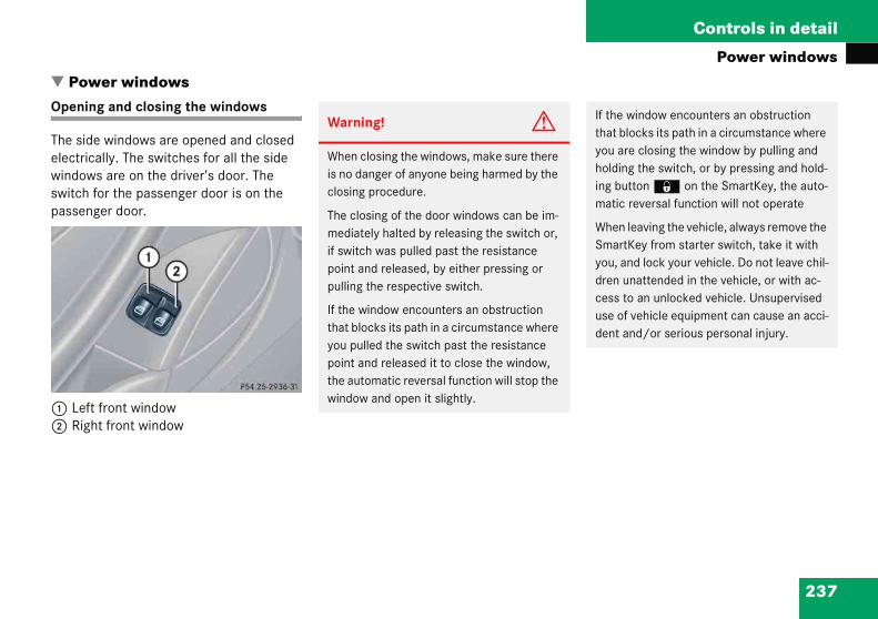
237
Controls in detail
Power windows
�Op
Thelewiswpa
12
If the window encounters an obstruction that blocks its path in a circumstance where you are closing the window by pulling and holding the switch, or by pressing and hold-ing button ‹ on the SmartKey, the auto-matic reversal function will not operate
When leaving the vehicle, always remove the SmartKey from starter switch, take it with you, and lock your vehicle. Do not leave chil-dren unattended in the vehicle, or with ac-cess to an unlocked vehicle. Unsupervised use of vehicle equipment can cause an acci-dent and/or serious personal injury.
Poweening
e side wctricall
ndows aitch forssenge
Left frRight f
r windowsand closing the windows
indows are opened and closed y. The switches for all the side re on the driver’s door. The
the passenger door is on the r door.
ont windowront window
Warning! G
When closing the windows, make sure there is no danger of anyone being harmed by the closing procedure.
The closing of the door windows can be im-mediately halted by releasing the switch or, if switch was pulled past the resistance point and released, by either pressing or pulling the respective switch.
If the window encounters an obstruction that blocks its path in a circumstance where you pulled the switch past the resistance point and released it to close the window, the automatic reversal function will stop the window and open it slightly.
238
Controls in detail
Power
� Swit
ully opening the windows xpress-open)
Press switch 1 or 2 past the resis-tance point and release.
The corresponding window opens com-pletely.
ully closing the windows xpress-close)
Pull switch 1 or 2 past the resis-tance point and release.
The corresponding window closes com-pletely.
iYou windopen(� pa
You cusingin th(� pacont
You cusingthe apane
windows
ch on the ignition (� page 33).
Opening the windows
� Press switch 1 or 2 to the resistance point.
The corresponding window will move downwards until you release the switch.
Closing the windows
� Pull switch 1 or 2 to the resistance point.
The corresponding window will move upwards until you release the switch.
F(E
�
F(E
�
can also open or close the power ows using the SmartKey (summer ing/convenience closing feature) ge 239).
an close and reopen the windows the air recirculation button ,
e climate control panel ge 173) or automatic climate
rol panel (� page 183).
an close and reopen the windows the charcoal filter button e in utomatic climate control l*(� page 183).
Warning G
If you pull and hold the switch up when clos-ing the window, and upward movement of the window is blocked by some obstruction including but not limited to arms, hands, fin-gers, etc., the automatic reversal will not op-erate.

239
Controls in detail
Power windows
Opening and closing the windows with the SmartKey
The panorama roof with power tilt/sliding panel* (� page 241) will also be opened or closed when the power windows are oper-ated with the SmartKey.
!If this bdurslig
Remswiand
If ththeholwillsen
Warning! G
Never operate the windows or panorama roof with power tilt/sliding panel* if there is the possibility of anyone being harmed by the opening or closing procedure.
In the event that the procedure causes po-tential danger, the procedure can be imme-diately halted by releasing the button on the SmartKey. To reverse direction of move-ment, press Œ for opening or ‹ for closing. ��
Stopping windows
� Press or pull respective switch again.
e upward movement of the window locked during the closing proce-e, the window will stop and open htly.
ove the obstruction, pull the tch again past the resistance point release.
e window still does not close when re is no obstruction, then pull and d the switch again. The side window then close without the obstruction sor function.
Warning! G
Driver's door only:If within five seconds you again pull the switch past the resistance point and re-lease, the automatic reversal will not func-tion.

240
Controls in detail
Power
� Aim hand
Opening
� Presunlo
The wpowebeginone
� Releproc
ynchronizing power windows
he power window must be resynchro-ized each time
after the battery has been disconnect-ed.
if the power windows cannot be fully opened (Express-open) or closed (Express-close).
Switch on the ignition (� page 33).
Pull the power window switches until the side windows are closed.
Hold the switches for approximately one second.
The power windows are synchronized.
��
windows
transmitter eye at the driver’s door le.
(Summer opening feature)
s and hold button Πafter cking the vehicle.
indows and panorama roof with r tilt/sliding panel* (� page 241) to open after approximately
second.
ase the Πbutton to stop edure.
Closing (Convenience feature)
� Press and hold button ‹ after lock-ing the vehicle.
The windows and panorama roof with power tilt/sliding panel* begin to close after approximately one second.
� Release the ‹ button to stop procedure.
Make sure all side windows and the pan-orama roof with power tilt/sliding panel* are properly closed before leaving the vehicle.
S
Tn
�
�
�
�

241
Controls in detail
of with power tilt/sliding panel*
�Opsupo
ThbliThrolpa
Thtilt
Ro
12
� Switch on the ignition (� page 33).
In a vehicle rollover, occupants not wearing their seat belts or not wearing them properly may be thrown out of the opening. Such an opening also presents a potential for injury for occupants wearing their seat belts prop-erly as entire body parts or portions of them may protrude from the passenger compart-ment.
When leaving the vehicle, always remove the SmartKey from starter switch, take it with you, and lock the vehicle. Do not leave chil-dren unattended in the vehicle, or with ac-cess to an unlocked vehicle. Unsupervised use of vehicle equipment can cause an acci-dent and/or serious personal injury.
Panoening nblindwer til
e tilt/snds aree switchler sunbnel.
e roller/slidin
of pane
, 4 Op, 3 Cl
Panorama ro
rama roof with power tilt/sliding panel*and closing the roller s for the panorama roof with t/sliding panel
liding panel and the roller sun- opened and closed electrically. for the tilt/sliding panel and the linds is on the overhead control
sunblinds only operate with the g panel closed.
l switch
en roller sunblindsose roller sunblinds
Warning! G
When opening or closing the tilt/sliding pan-el, make sure there is no danger of anyone being harmed by the opening or closing pro-cedure.
If the tilt/sliding panel is closed with the convenience closing feature and becomes blocked, it will not open automatically. Should this occur, press the Πbutton on the SmartKey and hold it down; the tilt/slid-ing panel opens again.
The panorama roof with power tilt/sliding panel is made out of glass. In the event of an accident, the glass may shatter. This may result in an opening in the roof.

242
Controls in detail
Panora
Openingsunblin
� To opmovetancdirec
Relerollesired
pening and closing the panorama roof ith power tilt/sliding panel
he tilt/sliding panel is opened and closed lectrically. The roof panel switch is locat-d on the overhead control panel.
he tilt/sliding panel only operates with e roller sunblinds opened.
oof panel switch
Push up to raise roof panel at rearPull down to lower roof panel at rearPush forward to slide roof panel closedPush back to slide roof panel open
Warni
When csure thaby the croller suby relea
ma roof with power tilt/sliding panel*
and closing the roller ds
en or close the roller sunblinds, the roof panel switch to the resis-
e point in the required tion 1 to 4.
ase the roof panel switch when the r sunblinds have reached the de- position.
Fully opening the roller sunblinds (Express-open)
� Move the roof panel switch past the resistance point in the required direction of arrow 1 or 4 and release.
The roller sunblinds open completely.
Stopping the roller sunblinds during Express-operation
� Move the roof panel switch in any direction.
Ow
Tee
Tth
R
1234
ng! G
losing the roller sunblinds, make t no one is in danger of being injured losing procedure. The closing of the nblinds can be immediately halted sing the switch.
243
Controls in detail
of with power tilt/sliding panel*
Warn
Whenel, mabeingcedur
The opaneling thpast tmovin
The clpaneling th
The ppanelaccidesult in
!To avoid damaging the seals, do not transport any objects with sharp edges which can stick out of the tilt/sliding panel. Do not open the tilt/sliding pan-el if there is snow or ice on the roof, as this could result in malfunctions.
The tilt/sliding panel can be opened or closed manually should an electrical malfunction occur (� page 381).
Panorama ro
ing! G
opening or closing the tilt/sliding pan-ke sure there is no danger of anyone harmed by the opening or closing pro-e.
pening procedure of the tilt/sliding can be immediately halted by releas-e switch or, if the switch was moved he resistance point and released, by g the switch in any direction.
osing procedure of the tilt/sliding can be immediately halted by releas-e switch.
anorama roof with power tilt/sliding is made out of glass. In the event of an nt, the glass may shatter. This may re- an opening in the roof.
In a vehicle rollover, occupants not wearing their seat belts or not wearing them properly may be thrown out of the opening. Such an opening also presents a potential for injury for occupants wearing their seat belts prop-erly as entire body parts or portions of them may protrude from the passenger compart-ment.
When leaving the vehicle, always remove the SmartKey from starter switch, take it with you, and lock the vehicle. Do not leave chil-dren unattended in the vehicle, or with ac-cess to an unlocked vehicle. Unsupervised use of vehicle equipment can cause an acci-dent and/or serious personal injury.

244
Controls in detail
Panora
� Swit
pening the panorama roof with power ilt/sliding panel with the SmartKey
he power windows (� page 237) will also e opened or closed when you operate the lt/sliding panel with the SmartKey.
iYou cing popen(� pa
You ing pbuttoel (�cont
You ing pton econt
Warning! G
Never operate the windows or tilt/sliding panel if there is the possibility of anyone be-ing harmed by the opening or closing proce-dure.
In the event that the procedure causes po-tential danger, the procedure can be imme-diately halted by releasing the button on the SmartKey. To reverse direction of move-ment, press Œ for opening or ‹ for closing.
ma roof with power tilt/sliding panel*
ch on the ignition (� page 33).
Opening and closing the panorama roof with power tilt/sliding panel
� To open, close, raise, or lower the tilt/sliding panel, move the roof panel switch to resistance point in the re-quired direction of arrows 1 to 4.
Release the roof panel switch when the tilt/sliding panel has reached the de-sired position.
Fully opening (Express-open) the panorama roof with power tilt/sliding panel
� Move the roof panel switch past the resistance point in the direction of arrow 4 and release.
The tilt/sliding panel opens completely.
Stopping the panorama roof with power tilt/sliding panel during Express-open
� Move the roof panel switch in any direction.
Ot
Tbti
an also open or close the tilt/slid-anel using the SmartKey (summer ing/convenience closing feature) ge 244).
can close and reopen the tilt/slid-anel using the air recirculation n , in the climate control pan-page 173) or automatic climate
rol panel (� page 183).
can close and reopen the tilt/slid-anel using the charcoal filter but-
in the automatic climate rol panel*(� page 183).

245
Controls in detail
of with power tilt/sliding panel*
� Aimhan
Openin
If the r
� Preunl
Thebegone
� Pre
The
Closing (Convenience feature)
� Press and hold button ‹ after lock-ing the vehicle.
The windows and the tilt/sliding panel begin to close after approximately one second.
� With the windows and tilt/sliding panel fully closed, press and hold button ‹ again.
The roller sunblind begins to close after approximately one second.
� Release the ‹ button to stop procedure.
Make sure all side windows and the tilt/sliding panel are properly closed before leaving the vehicle.
Panorama ro
transmitter eye at the driver‘s door dle.
g (Summer opening feature)
oller sunblind is closed:
ss and hold button Πafter ocking the vehicle.
windows and the roller sunblind in to open after approximately second.
ss and hold button Πagain.
tilt/sliding panel tilts.
� Press and hold button Œ again.
The tilt/sliding panel begins to open after approximately one second.
If roller sunblind is already open:
� Press and hold button Œ after unlocking the vehicle.
The windows move down and the tilt/sliding panel tilts after approxi-mately one second.
� With the windows fully open, press and hold button Œ again.
The tilt/sliding panel begins to slide open after approximately one second.
� Release the Œ button to stop procedure.
246
Controls in detail
Panora
Synchropower tsunblin
The tilt/synchro
� afterdisco
� afterclose
� the twith
� after
Move and hold the roof panel switch in the direction of arrow 3 until the tilt/sliding panel is fully closed.
Hold the roof panel switch for approximately one second.
Check the Express-open feature of the tilt/sliding panel (� page 244).
If the tilt/sliding panel opens com-pletely, the tilt/sliding panel is synchronized. Otherwise repeat the above steps.
ma roof with power tilt/sliding panel*
nizing the panorama roof with ilt/sliding panel and the roller ds
sliding panel after must be nized
the battery has been nnected or discharged
the tilt/sliding panel has been d manually
ilt/sliding panel has been opened an abrupt movement
a malfunction.
� Switch on the ignition (� page 33).
� Move and hold the roof panel switch in direction of arrow 3 (� page 242) until the roller sunblind are fully closed.
Hold the roof panel switch for approxi-mately one second.
� Move and hold the roof panel switch in direction of arrow 4 until the roller sunblinds are fully opened.
Hold the roof panel switch for approximately one second.
� Move and hold the roof panel switch in the direction of arrow 4 until the tilt/sliding panel is approximately 4 in (10 cm) opened.
Release the roof panel switch.
�
�

247
Controls in detail
Driving systems
�Thde
�
Fodritem
Warning! G
Cruise control is a convenience system designed to assist the driver during vehicle operation. The driver is and must remain at all times responsible for the vehicle speed and for safe brake operation.
Only use cruise control if the road, the traffic and weather conditions make it advisable to travel at a steady speed.
� The use of cruise control can be danger-ous on winding roads or in heavy traffic because conditions do not allow safe driving at a steady speed.
� The use of cruise control can be danger-ous on slippery roads. Rapid changes in tire traction can result in wheel spin and loss of control.
� Deactivate cruise control when driving in fog.
The “Resume” function should only be oper-ated if the driver is fully aware of the previ-ously set speed and wishes to resume this particular preset speed.
Drivine drivinscribed
Cruisecan m
r informving sy
s” (�
g systemsg system of your vehicle is on the following pages:
control, with which the vehicle aintain a preset speed
ation on the BAS, ABS and ESP stems, see “Driving safety sys-page 81).
Cruise control
Cruise control automatically maintains the speed you set for your vehicle.
Use of cruise control is recommended for driving at a constant speed for extended periods of time. You can set or resume cruise control at any speed over 20 mph (30 km/h).
The cruise control function is operated by means of the cruise control lever.
The cruise control lever is the uppermost lever on the left-hand side of the steering column.

248
Controls in detail
Drivin
1 Sets2 Sets3 Canc4 Resu
Setting
� Accespee
� Briefcont
The c
� Rempeda
Cruis
!Vehicles with automatic transmission: Moving the gear selector lever to position N while driving also cancels cruise control. However, the gear se-lector lever should not be moved to position N while driving, except to coast when the vehicle is in danger of skidding (e.g. on icy roads).
iVehicles with manual transmission: The set cruise controlled speed is switched off when declutching exceeds four seconds during downshifting a gear.
iThe last stored speed is canceled when you turn off the engine.
g systems
current or higher speed current or lower speedels cruise controlmes at last set speed
current speed
lerate or decelerate to the desired d.
ly lift 1 or depress 2 the cruise rol lever.
urrent speed is set.
ove your foot from the accelerator l.
e control is activated.
Canceling cruise control
There are several ways to cancel cruise control:
� Step on the brake pedal.
Cruise control is canceled. The last speed set is stored for later use.
or
� Briefly push the cruise control lever to position 3.
Cruise control is canceled. The last speed set is stored for later use.
iOn uphill or downhill grades, cruise control may not be able to maintain the set speed. Once the grade eases, the set speed will be resumed.

249
Controls in detail
Driving systems
Settin
� Liftandrea
� Rel
The
Settin
� Depposdes
� Rel
The
Setting to last stored speed (“Resume” function)
� Briefly push cruise control lever to position 4.
The cruise control resumes the last set speed.
� Remove your foot from the accelerator pedal.
iDepnotbriecruspe
Warning! G
The speed stored in memory should only be set again if prevailing road conditions per-mit. Possible acceleration or deceleration differences arising from returning to preset speed could cause an accident and/or seri-ous injury to you and others.
g a higher speed
cruise control lever to position 1 hold it up until the desired speed is ched.
ease cruise control lever.
new speed is set.
g a lower speed
ress cruise control lever to ition 2 and hold it down until the ired speed is reached.
ease cruise control lever.
new speed is set.
Fine adjustment in 1 mph (Canada: 1 km/h) increments
Faster
� Briefly tip cruise control lever in direction of arrow 1.
Slower
� Briefly tip cruise control lever in direction of arrow 2.
ressing the accelerator pedal does deactivate cruise control. After f acceleration (e.g. for passing),
ise control will resume the last ed set.
iVehicles with automatic transmission: When you use the cruise control lever to decelerate, the transmission will automatically downshift if the engine’s braking power does not brake the vehicle sufficiently.

Controls in detail
in
a
tb
plit rear bench seat
o expand the cargo area, you can fold own the left and right rear seat backrests.
he two sections can be folded down eparately.
i
nldde Warning! G
When expanding the luggage compartment, always fold the seat cushions fully forward.
Unless you are transporting cargo, the back-rests must remain properly locked in the up-right position.
In an accident, during hard braking or sud-den maneuvers, loose items will be thrown around inside the vehicle, and cause injury to vehicle occupants unless the items are securely fastened in the vehicle.
250
Load
Roof r
1 Fas2 Rub
Warn
Use oMerceavoid factur
g
ck*
ening pointser strip
� Mount the roof rack only between the fastening points 1 and in the recess of the rubber strip 2.
� Secure the roof rack according to manufacturer’s instructions for installation.
S
Td
Ts
ng! G
y roof racks approved by es-Benz for your vehicle model to amage to the vehicle. Follow manu-r’s installation instructions.
!Load the roof rack in such a way that the vehicle cannot be damaged while driving.
Make sure
� you can fully raise the tilt/sliding panel*.
� you can fully open the trunk lid.

251
Controls in detail
Loading
Foldin
1 Rel2 Sea3 Rel4 Bac
Setting up rear seat bench
1 Indicator
� Fold backrest rearward until it engag-es.
� Fold seat cushion rearward until it locks into position.
If the backrest is not locked into position, a red indicator 1 will be visible.
� Check for secure locking by pushing and pulling on the backrest. ��
g the backrest forward
ease handlet cushion ease lever krest
� Pull release handle 1.
� Fold seat cushion 2 forward.
� Fully retract and fold rearward head restraints (� page 104).
� Pull release lever 3.
� Fold backrest 4 forward.
!Always release the seat cushion and fold it forward before folding the seat backrests forward. Otherwise, the backrest covering may be damaged.

252
Controls in detail
Loadin
oading instructions
he total load weight including vehicle ccupants and luggage/cargo should not xceed the load limit or vehicle capacity eight indicated on the corresponding lacard located on the driver’s door -pillar.
he handling characteristics of a fully load-d vehicle depend greatly on the load dis-ibution. It is therefore recommended to ad the vehicle according to the illustra-ons shown, with the heaviest items being laced towards the front of the vehicle.
Warni
If a red up, theninto pos
Always when reextendeCheck fpulling
In an acden maaroundto vehicsecurel
To helpsion or when tr
��
g
Luggage cover
1 Securing straps
Removal
� Take off securing straps 1.
� Pull cover in direction of arrow 2.
Installation
� Place cover into holder.
� Attach securing straps to trunk lid.
L
ToewpB
Tetrlotip
ng! G
indicator is visible with the backrest the backrest is not properly locked ition.
lock backrest in its upright position ar seat bench is occupied, or the d cargo compartment is not in use. or secure locking by pushing and on the backrest.
cident, during hard braking or sud-neuvers, loose items will be thrown inside the vehicle, and cause injury le occupants unless the items are
y fastened in the vehicle.
avoid personal injury during a colli-sudden maneuver, exercise care ansporting cargo.
!Do not place anything on the luggage cover below the rear window.
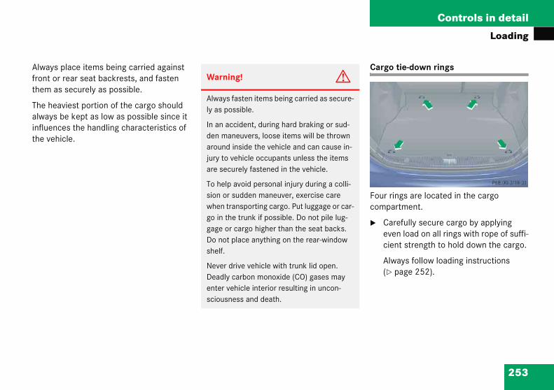
253
Controls in detail
Loading
Alwaysfront othem a
The healwaysinfluenthe veh
Cargo tie-down rings
Four rings are located in the cargo compartment.
� Carefully secure cargo by applying even load on all rings with rope of suffi-cient strength to hold down the cargo.
Always follow loading instructions (� page 252).
place items being carried against r rear seat backrests, and fasten s securely as possible.
aviest portion of the cargo should be kept as low as possible since it ces the handling characteristics of icle.
Warning! G
Always fasten items being carried as secure-ly as possible.
In an accident, during hard braking or sud-den maneuvers, loose items will be thrown around inside the vehicle and can cause in-jury to vehicle occupants unless the items are securely fastened in the vehicle.
To help avoid personal injury during a colli-sion or sudden maneuver, exercise care when transporting cargo. Put luggage or car-go in the trunk if possible. Do not pile lug-gage or cargo higher than the seat backs. Do not place anything on the rear-window shelf.
Never drive vehicle with trunk lid open. Deadly carbon monoxide (CO) gases may enter vehicle interior resulting in uncon-sciousness and death.
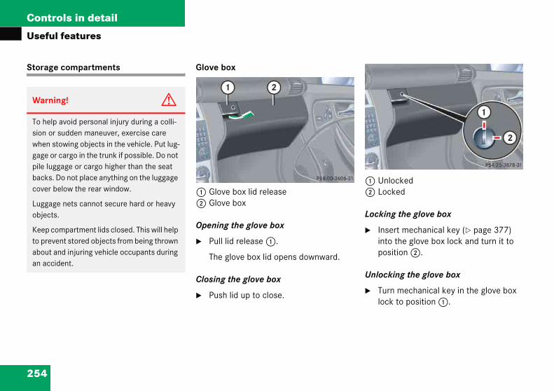
Controls in detail
l
e
UnlockedLocked
ocking the glove box
Insert mechanical key (� page 377) into the glove box lock and turn it to position 2.
nlocking the glove box
Turn mechanical key in the glove box lock to position 1.
i
lpr
strg. D b
gts
cove aci
254
Usefu
Storag
Warn
To hesion owhengage opile lubackscover
Luggaobjec
Keep to preaboutan ac
features
compartments Glove box
1 Glove box lid release2 Glove box
Opening the glove box
� Pull lid release 1.
The glove box lid opens downward.
Closing the glove box
� Push lid up to close.
12
L
�
U
�
ng! G
avoid personal injury during a colli-sudden maneuver, exercise care owing objects in the vehicle. Put lug- cargo in the trunk if possible. Do not gage or cargo higher than the seat
o not place anything on the luggage elow the rear window.
e nets cannot secure hard or heavy .
mpartment lids closed. This will help nt stored objects from being thrown
nd injuring vehicle occupants during dent.
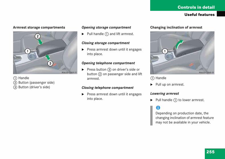
255
Controls in detail
Useful features
Armre
1 Han2 But3 But
Changing inclination of armrest
1 Handle
� Pull up on armrest.
Lowering armrest
� Pull handle 1 to lower armrest.
iDepending on production date, the changing inclination of armrest feature may not be available in your vehicle.
st storage compartments
dleton (passenger side)ton (driver’s side)
Opening storage compartment
� Pull handle 1 and lift armrest.
Closing storage compartment
� Press armrest down until it engages into place.
Opening telephone compartment
� Press button 3 on driver’s side or button 2 on passenger side and lift armrest.
Closing telephone compartment
� Press armrest down until it engages into place.

256
Controls in detail
Useful
Cup hol urning the swiveling cup holder utward
Turn the cup holder in the direction of arrow 2 until it engages.
You can now use both cup holders.
Warni
In ordevehiclefit into ttainers where tcould svers, or
When nclosed.to you obrakingdent.
Keep inholder mcle manthrownObjectsor may persona
features
ders in front of seat armrest Underneath the swiveling cup holder is another stationary cup holder. You can only use this when the swiveling cup holder is pulled out and completely turned outward.
Sliding out the swiveling cup holder
� Press button 1.
The cup holder slides upward.
To
�
ng! G
r to help prevent spilling liquids on occupants, only use containers that he cup holder. Use lids on open con-and do not fill containers to a height he contents, especially hot liquids, pill during braking, vehicle maneu- in an accident.
ot in use, keep the cup holder An open cup holder may cause injury r others when contacted during
, vehicle maneuvers, or in an acci-
mind that objects placed in the cup ay come loose during braking, vehi-
euvers, or in an accident and be around in the vehicle interior. thrown around in the vehicle interi-cause an accident and/or serious l injury.
!No objects should be in the swiveling cup holder when the swiveling cup holder is slided upward. Otherwise the swiveling cup holder or the objects could be damaged.

257
Controls in detail
Useful features
Turninand sli
� Turarro
Turarro
Ashtrays
Center console ashtray
1 Cover plate2 Sliding button3 Ashtray insert
� Briefly press the bottom of cover plate 1.
The cover plate 1 opens automatically.
!No cupholOththe
g the swiveling cup holder inward ding it in
n the cup holder in the direction of w 3 until it engages.
n the cup holder in the direction of w 4 until it engages.
Parcel net in front passenger footwell
A small convenience parcel net is located in the front passenger footwell. It is for small and light items, such as road maps, mail, etc.
objects should be in the stationary holder when the swiveling cup der is turned inward and pushed in. erwise the swiveling cup holder or objects could be damaged.
Warning! G
Do not place heavy or fragile objects, or ob-jects having sharp edges, in the parcel net.
In an accident, during hard braking or sud-den maneuvers, they could be thrown around inside the vehicle, and cause injury to vehicle occupants.
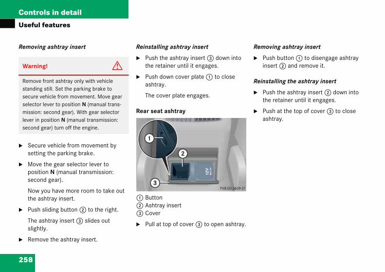
258
Controls in detail
Useful
Removi
� Secusetti
� Movepositseco
Nowthe a
� Push
The asligh
� Rem
emoving ashtray insert
Push button 1 to disengage ashtray insert 2 and remove it.
einstalling the ashtray insert
Push the ashtray insert 2 down into the retainer until it engages.
Push at the top of cover 3 to close ashtray.
Warni
Removestandinsecure selectomissionlever insecond
features
ng ashtray insert
re vehicle from movement by ng the parking brake.
the gear selector lever to ion N (manual transmission: nd gear).
you have more room to take out shtray insert.
sliding button 2 to the right.
shtray insert 3 slides out tly.
ove the ashtray insert.
Reinstalling ashtray insert
� Push the ashtray insert 3 down into the retainer until it engages.
� Push down cover plate 1 to close ashtray.
The cover plate engages.
Rear seat ashtray
1 Button2 Ashtray insert3 Cover
� Pull at top of cover 3 to open ashtray.
R
�
R
�
�
ng! G
front ashtray only with vehicle g still. Set the parking brake to vehicle from movement. Move gear r lever to position N (manual trans-: second gear). With gear selector position N (manual transmission: gear) turn off the engine.

259
Controls in detail
Useful features
Cigare
1 Cov2 Cig
� Sw
� Briepla
The
� Pus
Theaut
� Push down cover plate 1 to close ashtray.
The cover plate engages.
iThe lighter socket can be used to accommodate electrical accessories up to a maximum 85 W.
tte lighter
er platearette lighter
itch on the ignition (� page 33).
fly press the bottom of cover te 1.
ashtray opens automatically.
h in cigarette lighter 2.
cigarette lighter will pop out omatically when hot.
Warning! G
Never touch the heating element or sides of the lighter; they are extremely hot. Hold the knob only.
When leaving the vehicle, always remove the SmartKey from the starter switch, take it with you, and lock the vehicle. Do not leave children unattended in the vehicle, or with access to an unlocked vehicle. Unsuper-vised use of vehicle equipment may cause an accident and/or serious personal injury.
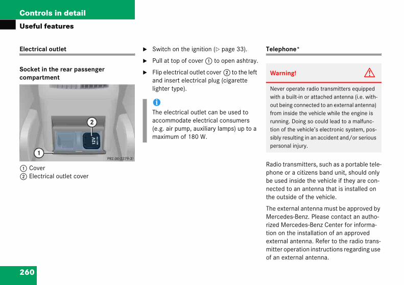
260
Controls in detail
Useful
Electric
Socket compar
1 Cove2 Elect
elephone*
adio transmitters, such as a portable tele-hone or a citizens band unit, should only e used inside the vehicle if they are con-ected to an antenna that is installed on e outside of the vehicle.
he external antenna must be approved by ercedes-Benz. Please contact an autho-zed Mercedes-Benz Center for informa-on on the installation of an approved xternal antenna. Refer to the radio trans-itter operation instructions regarding use
f an external antenna.
Warning! G
Never operate radio transmitters equipped with a built-in or attached antenna (i.e. with-out being connected to an external antenna) from inside the vehicle while the engine is running. Doing so could lead to a malfunc-tion of the vehicle’s electronic system, pos-sibly resulting in an accident and/or serious personal injury.
features
al outlet
in the rear passenger tment
rrical outlet cover
� Switch on the ignition (� page 33).
� Pull at top of cover 1 to open ashtray.
� Flip electrical outlet cover 2 to the left and insert electrical plug (cigarette lighter type).
T
Rpbnth
TMritiemo
iThe electrical outlet can be used to accommodate electrical consumers (e.g. air pump, auxiliary lamps) up to a maximum of 180 W.
261
Controls in detail
Useful features
Tele Aid*Warn
Pleaserespodriverhis/hyour srecomtion aphoneIf youdrivinand oweathjurisdcellulaOnly oagemtem ifpermiBear i(approcoverly 14
1 Obser
!The initial activation of the Tele Aid system may only be performed by completing the subscriber agreement and placing an acquaintance call using the ¡ button. Failure to complete either of these steps will result in a system that is not activated.
If you have any questions regarding ac-tivation, please call the Response Cen-ter at 1-800-756-9018 (in the USA) or 1-888-923-8367 (in Canada).
You can take and place telephone calls us-ing the s and t buttons on the steering wheel. To carry out other tele-phone functions, use the control system (� page 153).
See separate operating manual for instruc-tions on how to use the telephone.
ing! G
do not forget that your primary nsibility is to drive the vehicle. A ’s attention to the road must always be er primary focus when driving. For afety and the safety of others, we mend that you pull over to a safe loca-
nd stop before placing or taking a tele- call.
choose to use the telephone1 while g, please use the hands-free device nly use the telephone when road, er and traffic conditions permit. Some ictions prohibit the driver from using a r telephone while driving a vehicle.perate the COMAND* (Cockpit Man-
ent and Data System) and audio sys- road, weather and traffic conditions t. n mind that at a speed of just 30 mph ximately 50 km/h), your vehicle is
ing a distance of 44 feet (approximate-m) every second.
ve all legal requirements.
262
Controls in detail
Useful
The Tele
(Telemamand)
The Teletypes of
� auto
� road
� infor
The Teleing that properlycellular
The spebe adjuson the mraise, prpress bube adjusaudio sy
� To acRoadthe Iing o
ystem self-check
itially, after switching on ignition, mal-nctions are detected and indicated (the dicator lamps in the SOS button, the oadside Assistance button • and the formation button ¡ stay on longer an ten seconds or do not come on). The essage Tele Aid malfunction. Drive o workshop appears for approximately n seconds in the multifunction display.
features
Aid system
tic Alarm Identification on De-
Aid system consists of three response:
matic and manual emergency
side assistance and
mation
Aid system is operational provid-the vehicle’s battery is charged, connected, not damaged and and GPS coverage is available.
aker volume of a Tele Aid call can ted when using the volume control ultifunction steering wheel. To
ess button æ and to lower, tton ç . The volume can also ted using the volume knob on your stem or COMAND* head unit.
tivate, press the SOS button, the side Assistance button • or
nformation button ¡, depend-n the type of response required.
Shortly after the completion of your Tele Aid acquaintance call, you will receive a user ID and password. By visiting www.mbusa.com and selecting “Tele Aid” (USA only), you will have access to account information, remote door unlock and more.
S
InfuinRInthmtte
iThe SOS button is located above the in-side rear view mirror.
The Roadside Assistance button • and the Information button ¡ are located below the center armrest cover.
!The Tele Aid system utilizes the cellular network for communication and the GPS (Global Positioning System) satel-lites for vehicle location. If either of these signals are unavailable, the Tele Aid system may not function and if this occurs, assistance must be sum-moned by other means.

263
Controls in detail
Useful features
A voice connection between the Response Center and the occupants of the vehicle will be established automatically soon after the emergency call has been initiat-ed. The Response Center will attempt to determine more precisely the nature of the emergency provided they can speak to an occupant of the vehicle.
The Tele Aid system is available if:
� it has been activated and is operation-al. Activation requires a subscription for monitoring services, connection and cellular air time
� the relevant cellular phone network and GPS signals are available and pass the information on to the Response Center
Warn
If the the Rothe InconstTeleworksdisplafuncti
If a maboveexpecnearepossib
iLocation of the vehicle on a map is only possible if the vehicle is able to receive signals from the GPS satellite network and pass the information on to the Response Center.
Emergency calls
An emergency call is initiated automatical-ly following an accident in which the emer-gency tensioning devices (ETDs) or air bags deploy.
An emergency call can also be initiated manually by opening the cover next to the interior rear view mirror labeled SOS, then briefly pressing the button located under the cover. See (� page 264) for instruc-tions on initiating an emergency call man-ually.
Once the emergency call is in progress, the indicator lamp in the SOS button will begin to flash. The message Connecting call appears in the multifunction display and the audio system is muted. When the con-nection is established, the message Call connected appears in the multifunc-tion display. All information relevant to the emergency, such as the location of the vehicle (determined by the GPS satellite location system), vehicle model, identifica-tion number and color are generated.
ing! G
indicator lamps in the SOS button, in adside Assistance button and/or in
formation button remain illuminated antly in red and/or the message Aid malfunction. Drive to hop is displayed in the multifunction y after the system self-check, a mal-on in the system has been detected.
alfunction is indicated as outlined , the system may not operate as ted. Have the system checked at the st Mercedes-Benz Center as soon as le.

264
Controls in detail
Useful
Warni
If the inflashingvoice coestablisnot initvant ceThe memultifunten sec
Should moned
Warning! G
If you feel at any way in jeopardy when in the vehicle (e.g. smoke or fire in the vehicle, vehicle in a dangerous road location), please do not wait for voice contact after you have pressed the emergency button. Carefully leave the vehicle and move to a safe loca-tion. The Response Center will automatically contact local emergency officials with the vehicle’s approximate location if they re-ceive an automatic SOS signal and cannot make voice contact with the vehicle occu-pants.
features
Initiating an emergency call manually
1 Cover2 SOS button
� Briefly press on cover 1.
The cover will open.
� Press SOS button 2 briefly.
The indicator lamp in SOS button 2 will flash until the emergency call is concluded.
� Wait for a voice connection to the Re-sponse Center.
� Close cover 1 after the emergency call is concluded.
ng! G
dicator lamp in the SOS button is continuously and there was no nnection to the Response Center hed, then the Tele Aid system could
iate an emergency call (e.g. the rele-llular phone network is not available). ssage Call failed. appears in the ction display for approximately
onds.
this occur, assistance must be sum-by other means.

265
Controls in detail
Useful features
Roads
The Rolocated
� Pretha
A csistTheprocaldis
When tmessamultifuwill traidentification and GP
A voiceAssistaof the
� Desass
iThe indicator lamp in the Roadside As-sistance button • remains illumi-nated in red for approximately ten seconds during the system self-check after switching on ignition (together with the SOS button and the Information button ¡).
See system self-check (� page 262) when the indicator lamp does not come on in red or stays on longer than approximately ten seconds.
If the indicator lamp in the Roadside Assistance button • is flashing con-tinuously and there was no voice con-nection to the Response Center established, then the Tele Aid system could not initiate a Roadside Assis-tance call (e.g. the relevant cellular phone network is not available). The message Call failed. appears in the multifunction display.
ide Assistance button •
adside Assistance button • is below the center armrest cover.
ss and hold the button (for longer n two seconds).
all to a Mercedes-Benz Roadside As-ance dispatcher will be initiated. button will flash while the call is in gress. The message Connecting l will appear in the multifunction play and the audio system is muted.
he connection is established, the ge Call connected appears in the nction display. The Tele Aid system nsmit data generating the vehicle cation number, model, color and lo-(subject to availability of cellular S signals).
connection between the Roadside nce dispatcher and the occupants
vehicle will be established.
cribe the nature of the need for istance.
The Mercedes-Benz Roadside Assistance dispatcher will either dispatch a qualified Mercedes-Benz technician or arrange to tow your vehicle to the nearest Mercedes-Benz Center. For services such as labor and/or towing, charges may ap-ply. Refer to the Roadside Assistance man-ual for more information.
The following is only available in the USA:
� Sign and Drive services: Services such as jump start, a few gallons of fuel or the replacement of a flat tire with the vehicle spare tire are obtainable.

266
Controls in detail
Useful
Informa
The Infobelow th
� Presthan
A cater wflashmessin thdio s
When thmessagemultifunwill tran
Roadtermthe mrespphonCOM
See System self-check (� page 262) when the indicator lamp does not come on in red or stays on longer than ap-proximately ten seconds.
If the indicator lamp in the Information button ¡ is illuminated continuous-ly and there was no voice connection to the Response Center established, then the Tele Aid system could not initiate an Information call (e.g. the relevant cellular phone network is not avail-able). The message Call failed. appears in the multifunction display.
Information calls can be terminated using the t button on the multi-function steering wheel or the respec-tive button for ending a telephone call on the audio system or COMAND* head unit.
features
tion button ¡
rmation button ¡ is located e center armrest cover.
s and hold the button (for longer two seconds).
ll to the Customer Assistance Cen-ill be initiated. The button will while the call is in progress. The age Connecting call will appear
e multifunction display and the au-ystem is muted.
e connection is established, the Call connected appears in the
ction display. The Tele Aid system smit data generating the vehicle
identification number, model, color and lo-cation (subject to availability of cellular and GPS signals).
A voice connection between the Customer Assistance Center representative and the occupants of the vehicle will be estab-lished. Information regarding the operation of your vehicle, the nearest Mercedes-Benz Center or Mercedes-Benz USA products and services is available to you.
For more details concerning the Tele Aid system, please visit www.mbusa.com and use your ID and password (sent to you separately) to learn more (USA only).
side Assistance calls can be inated using the t button on ultifunction steering wheel or the
ective button for ending a tele-e call on the audio system or AND* head unit.
iThe indicator lamp on the Information button ¡ remains illuminated in red for approximately ten seconds during the system self-check after switching on ignition (together with the “SOS” button and the Roadside Assistance button •).

267
Controls in detail
Useful features
!If thingremthemarenVishavthe1-81-8as
iThe indicator lamp in the respective button flashes until the call is conclud-ed. Calls can only be terminated by a Response Center or Customer Assis-tance Center representative except Roadside Assistance and Information calls, which can also be terminated by pressing button t on the multifunc-tion steering wheel or the respective button for ending a telephone call on the audio system or COMAND* head unit.
Upgrade scenario
An emergency call is possible even if other services are active.
e indicator lamps do not start flash- after pressing one of the buttons or ain illuminated (in red) at any time,
Tele Aid system has detected a lfunction or the service is not cur-tly active, and may not initiate a call. it your Mercedes-Benz Center and e the system checked or contact Response Center at 00-756-9018 (in the USA) or 88-923-8367 (in Canada) as soon possible.
!If the indicator lamp continues to flash or the system does not reset, contact the Response Center at 1-800-756-9018 (in the USA) or 1-888-923-8367 (in Canada), or Mercedes-Benz Customer Assistance at 1-800-FOR-MERCedes (1-800-367-6372) in the USA or Customer Service at 1-800-387-0100 in Canada.

268
Controls in detail
Useful
iWhethe asysteed mThe oswitcphonDiscthe csysterun. ter ismanthe RA poCOMTele
iThe remote door unlock feature is avail-able if the relevant cellular phone net-work is available.
The SOS button will flash and the mes-sage Connecting call will appear in the multifunction display to indicate receipt of the door unlock command.
Once the vehicle is unlocked, a Response Center specialist will attempt to establish voice contact with the vehicle occupants.
If the trunk lid recessed handle was pulled for more than 20 seconds be-fore door unlock authorization was re-ceived by the Response Center, you must wait 15 minutes before pulling the trunk lid recessed handle again.
features
Remote door unlock
In case you have locked your vehicle unin-tentionally (e.g. SmartKey inside vehicle), and the reserve key is not handy:
� Contact the Mercedes-Benz Response Center at 1-800-756-9018 (in the USA) or 1-888-923-8367 (in Canada).
You will be asked to provide your pass-word which you provided when you completed the subscriber agreement.
� Then return to your vehicle and pull the trunk lid recessed handle for minimum of 20 seconds until the SOS button is flashing.
The message Connecting call appears in the multifunction display.
As an alternative, you may unlock the vehi-cle via Internet using the ID and password sent to you shortly after the completion of your acquaintance call.
The Response Center will then unlock your vehicle with the remote door unlocking feature.
n a Tele Aid call has been initiated, udio system or the COMAND* m audio is muted and the select-ode (radio, tape or CD) pauses. ptional cellular phone (if installed) hes off. If you must use this e, the vehicle must be parked.
onnect the coiled cord and place all. The COMAND* navigation m (if engaged) will continue to
The display in the instrument clus- available for use and spoken com-ds are only available by pressing PT button on the COMAND* unit.
p-up window will appear in the AND* display to indicate that a Aid call is in progress.

269
Controls in detail
Useful features
Stolen
In the
� Rep
Theinc
� PasMewityou
Theto cTellocconyoupro
Remote control integrated into the interior rear view mirror
1 Indicator lamp
2 3 4 Signal transmitter button
5 Hand-held transmitter button
6 Hand-held remote control trans-mitter (not part of the vehicle equipment)
Vehicle Recovery services
event your vehicle was stolen:
ort the incident to the police.
police will issue a numbered ident report.
s this number on to the rcedes-Benz Response Center along h your password issued to you when subscribed to the service.
Response Center will then attempt overtly contact the vehicle’s
e Aid system. Once the vehicle is ated, the Response Center will tact the local law enforcement and . The vehicle’s location will only be vided to law enforcement.
Garage door opener*
The built-in remote control is capable of operating up to three separately controlled devices, for example garage door openers, gate openers, or other devices compatible with HomeLink® or some other systems.
You can program the signal transmitter buttons.
iWhen the anti-theft alarm or the tow-away alarm stays on for more than 30 seconds, a call is initiated automatically to the Response Center, see “Anti-theft alarm system*” (� page 86) and “Tow away alarm*” (� page 87).
270
Controls in detail
Useful
Warni
Before controloperatoout of tpotentiming a up or doator, th
Do not with anty stop U.S. fedany gartured bthat candoor tocurrent
iUSA only:This device complies with Part 15 of the FCC Rules. Operation is subject to the following two conditions:
(1) This device may not cause harmful interference, and
(2) this device must accept any inter-ference received, including interfer-ence that may cause undesired operation.
Any unauthorized modification to this device could void the user’s authority to operate the equipment.
features
ng! G
programming the integrated remote to a garage door opener or gate r, make sure people and objects are he way of the device to prevent al harm or damage. When program-garage door opener, the door moves wn. When programming a gate oper-
e gate opens or closes.
use the integrated remote control y garage door opener that lacks safe-and reverse features as required by eral safety standards (this includes
age door opener model manufac-efore April 1, 1982). A garage door not detect an object - signaling the
stop and reverse - does not meet U.S. federal safety standards.
iCertain types of garage door openers are incompatible with the integrated opener. If you should experience diffi-culties with programming the transmit-ter, contact an authorized Mercedes-Benz Center, or call Mercedes-Benz Customer Assistance Center (in the USA) at 1-800-FOR-MERCedes, or Customer Service (in Canada) at 1-800-387-0100.

271
Controls in detail
Useful features
Step 3:
� Hold the end of the hand-held remote control transmitter 6 of the device you wish to train approximately 2 to 5 in (5 to12 cm) away from the surface of the integrated remote control locat-ed on the interior rear view mirror, keeping the indicator lamp 1 in view.
Step 4:
� Using both hands, simultaneously press the hand-held transmitter button 5 and the desired integrated signal transmitter button (2, 3 or 4). Do not release the buttons until completing step 5.
The indicator lamp 1 on the integrat-ed remote control will flash, first slowly and then rapidly.
iCanThiIndto t
(1)
(2)
Anydevto o
��
Programming or reprogramming the in-tegrated remote control
Step 1:
� Switch on the ignition (� page 33).
Step 2:
� If you have previously programmed an integrated signal transmitter button and wish to retain its programming, proceed to step 3. Otherwise, press and hold the two outer signal transmit-ter buttons 2 and 4 and release them only when the indicator lamp 1 begins to flash after approximately 20 seconds (do not hold the button for longer than 30 seconds). This proce-dure erases any previous settings for all three channels and initializes the memory. If you later wish to program a second and/or third hand-held trans-mitter to the remaining two signal transmitter buttons, do not repeat this step and begin directly with step 3.
ada only: s device complies with RSS-210 of ustry Canada. Operation is subject he following two conditions:
This device may not cause interfer-ence, and
this device must accept any inter-ference received, including interfer-ence that may cause undesired operation of the device.
unauthorized modification to this ice could void the user’s authority perate the equipment.
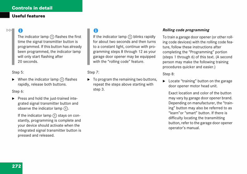
272
Controls in detail
Useful
Step 5:
� Wherapid
Step 6:
� Presgrateobse
If thestanyourintegpres
olling code programming
o train a garage door opener (or other roll-g code devices) with the rolling code fea-re, follow these instructions after
ompleting the “Programming” portion teps 1 through 6) of this text. (A second erson may make the following training rocedures quicker and easier.)
tep 8:
Locate “training” button on the garage door opener motor head unit.
Exact location and color of the button may vary by garage door opener brand. Depending on manufacturer, the “train-ing” button may also be referred to as “learn”or “smart” button. If there is difficulty locating the transmitting button, refer to the garage door opener operator’s manual.
iThe itimeprogbeenwill o20 s
��
features
n the indicator lamp 1 flashes ly, release both buttons.
s and hold the just-trained inte-d signal transmitter button and rve the indicator lamp 1.
indicator lamp 1 stays on con-tly, programming is complete and device should activate when the rated signal transmitter button is sed and released.
Step 7:
� To program the remaining two buttons, repeat the steps above starting with step 3.
R
Tintuc(spp
S
�
ndicator lamp 1 flashes the first the signal transmitter button is rammed. If this button has already programmed, the indicator lamp nly start flashing after
econds.
iIf the indicator lamp 1 blinks rapidly for about two seconds and then turns to a constant light, continue with pro-gramming steps 8 through 12 as your garage door opener may be equipped with the “rolling code” feature.
273
Controls in detail
Useful features
Step 9
� Predoo
The
You hafollowi
Step 1
� Firmrelesigor 4
Step 1
� Prerelecom
Some gcode eperformcomple
Step 1
Step 4:
� Continue to press and hold the inte-grated signal transmitter button (2, 3 or 4) while you press and re-press (“cycle”) your hand-held remote con-trol transmitter 6 every two seconds until the frequency signal has been learned. Upon successful training, the indicator lamp 1 will flash slowly and then rapidly after several seconds.
� Proceed with programming step 5 and step 6 to complete.
Operation of integrated remote control
� Switch on the ignition.
� Select and press the appropriate inte-grated signal transmitter button (2, 3 or 4) to activate the remote con-trolled device.
The integrated remote control trans-mitter continues to send the signal as long as the button is pressed – up to 20 seconds.
:
ss “training” button on the garage r opener motor head unit.
“training light” is activated.
ve 30 seconds to initiate the ng step.
0:
ly press, hold for two seconds and ase the programmed integrated
nal transmitter button (2, 3 ).
1:
ss, hold for two seconds and ase same button a second time to plete the training process.
arage door openers (or other rolling quipped devices) may require you to
this procedure a third time to te the training.
2:
� Confirm the garage door operation by pressing the programmed integrated signal transmitter button (2, 3 or 4).
Step 13:
� To program the remaining two buttons, repeat the steps above starting with step 3.
Gate operator/Canadian programming
Canadian radio-frequency laws require transmitter signals to “time-out” (or quit) after several seconds of transmission which may not be long enough for the inte-grated signal transmitter to pick up the signal during programming. Similar to this Canadian law, some U.S. gate operators are designed to “time-out” in the same manner.
If you live in Canada or if you are having difficulties programming a gate operator (regardless of where you live) by using the programming procedures, replace step 4 with the following:
274
Controls in detail
Useful
Erasing
� Swit
� Simutransapprindichold
The ceras
iIf youof al
features
the remote control memory
ch on the ignition.
ltaneously hold down the signal mitter buttons 2 and 4, for oximately 20 seconds, until the ator lamp 1 blinks rapidly. Do not for longer than 30 seconds.
odes of all three channels are ed.
Reprogramming a single integrated signal transmitter button
To program a device using a signal trans-mitter button previously trained, follow these steps:
� Press and hold the desired signal trans-mitter button (2, 3 or 4). Do not release the button.
� The indicator lamp will begin to flash af-ter 20 seconds. Without releasing the integrated signal transmitter button, proceed with programming starting with step 3.
sell your vehicle, erase the codes l three channels.

275
Operation
The first 1000 miles (1500km)
Driving instructions
At the gas station
Engine compartment
Tires and wheels
Winter driving
Maintenance
Vehicle care

Operation
“On
ir
Avoid accelerating by kick-down.
Do not attempt to slow the vehicle down by shifting to a lower gear using the gear selector lever.
Select positions 3, 2 or 1 only when driving at moderate speeds (for hill driving).
Select C as the preferred shift program (� page 164) for the first 1000 miles (1500 km).
fter 1000 miles (1500 km) you may grad-ally increase vehicle and engine speeds the permissible maximum.
ll of the above instructions also apply hen driving the first 1000 miles 500 km) after the engine or the rear dif-rential has been replaced.
iAlways obey applicable speed limits.
276
In the tailed iing and
The f
peration” section you will find de-formation on operating, maintain-caring for your vehicle.
st 1000 miles (1500km)
The more cautiously you treat your vehicle during the break-in period, the more satis-fied you will be with its performance later on.
� Drive your vehicle during the first 1000 miles (1500 km) at varying but moderate vehicle and engine speeds.
� During this period, avoid heavy loads (full throttle driving) and excessive engine speeds (no more than 2/3 of maximum rpm in each gear).
� Shift gears in a timely manner.
�
�
�
�
Auto
Aw(1fe

277
Operation
Driving instructions
�Dr
Fupedit
To
�
�
�
�
�
�
Fuingon
Pedals
Power assistance
Warning! G
Keep driver’s foot area clear at all times. Ob-jects stored in this area may impair pedal movement.
Warning! G
With the engine not running, there is no power assistance for the brake and steering systems. In this case, it is important to keep in mind that a considerably higher degree of effort is necessary to brake and steer the vehicle.
Drivinive sen
el consnds on ions.
save fu
Keep ttion pr
Remov
Remov
Allow load u
Avoid eration
Have aby quaspecifand asservicMerce
el cons in cold short t
g instructionssibly – save fuel
umption, to a great extent, de-driving habits and operating con-
el you should:
ires at the recommended infla-essures
e unnecessary loads
e roof rack when not in use
engine to warm up under low se
frequent acceleration and decel-
ll maintenance work performed lified technicians at the intervals ied in the Maintenance Booklet required by the maintenance
e display. Contact an authorized des-Benz Center
umption is also increased by driv- weather, in stop-and-go traffic, rips and in hilly area.
Drinking and driving
Warning! G
Drinking and driving and/or taking drugs and driving are very dangerous combina-tions. Even a small amount of alcohol or drugs can affect your reflexes, perceptions and judgement.
The possibility of a serious or even fatal ac-cident are greatly increased when you drink or take drugs and drive.
Do not drink or take drugs and drive or allow anyone to drive who has been drinking or taking drugs.
278
Operation
Drivin
Brakes rake pad wear or a leak in the system may e the reason for low brake fluid in the res-rvoir.
ave the brake system inspected by quali-ed technicians immediately. Contact an uthorized Mercedes-Benz Center.
ll checks and service work on the brake ystem should be carried out by qualified chnicians only. Contact an authorized ercedes-Benz Center.
stall only brake pads and brake fluid commended by Mercedes-Benz.
Warni
After drwithoutter deethe firsreducedbe neceeffect. cles in
Restingcause ebrake p
It can atherebytivenesvehicleacciden
Warning! G
If other than recommended brake pads are installed, or other than recommended brake fluid is used, the braking properties of the vehicle can be degraded to an extent that safe braking is substantially impaired. This could result in an accident.
g instructions
To help prevent brake disk corrosion after driving on wet road surfaces (particularly salted roads), it is advisable to brake the vehicle with considerable force prior to parking. The heat generated serves to dry the brakes.
If your brake system is normally only sub-jected to moderate loads, you should occa-sionally test the effectiveness of the brakes by applying above-normal braking pressure at higher speeds. This will also enhance the grip of the brake pads.
If the parking brake is released and the brake warning lamp in the instrument clus-ter stays on, the brake fluid level in the res-ervoir is too low.
Bbe
Hfia
AsteM
Inre
ng! G
iving in heavy rain for some time applying the brakes or through wa-p enough to wet brake components, t braking action may be somewhat and increased pedal pressure may ssary to obtain expected braking
Maintain a safe distance from vehi-front.
your foot on the brake pedal will xcessive and premature wear of the ads.
lso result in the brakes overheating, significantly reducing their effec-s. It may not be possible to stop the in sufficient time to avoid an t.
!Be very careful not to endanger other road users when you apply the brakes.
Refer to the description of the Brake Assist System (BAS), (� page 82).
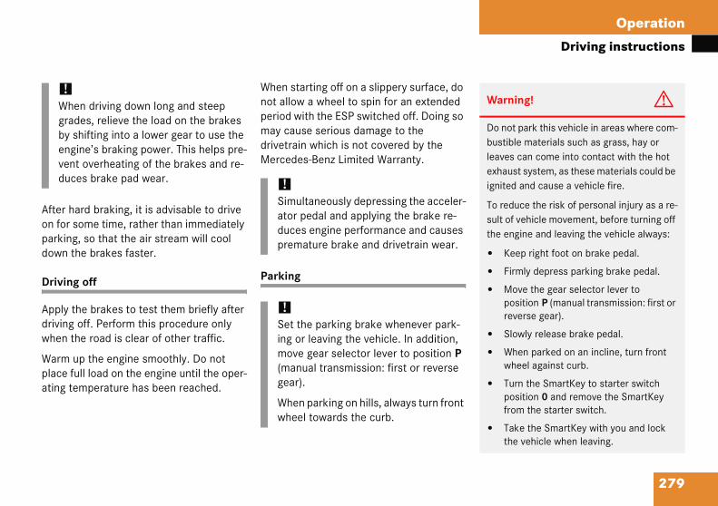
279
Operation
Driving instructions
After hon for parkingdown t
Drivin
Apply tdrivingwhen t
Warm place fating t
!Whgraby engvenduc
Warning! G
Do not park this vehicle in areas where com-bustible materials such as grass, hay or leaves can come into contact with the hot exhaust system, as these materials could be ignited and cause a vehicle fire.
To reduce the risk of personal injury as a re-sult of vehicle movement, before turning off the engine and leaving the vehicle always:
� Keep right foot on brake pedal.
� Firmly depress parking brake pedal.
� Move the gear selector lever to position P (manual transmission: first or reverse gear).
� Slowly release brake pedal.
� When parked on an incline, turn front wheel against curb.
� Turn the SmartKey to starter switch position 0 and remove the SmartKey from the starter switch.
� Take the SmartKey with you and lock the vehicle when leaving.
ard braking, it is advisable to drive some time, rather than immediately , so that the air stream will cool
he brakes faster.
g off
he brakes to test them briefly after off. Perform this procedure only he road is clear of other traffic.
up the engine smoothly. Do not ull load on the engine until the oper-emperature has been reached.
When starting off on a slippery surface, do not allow a wheel to spin for an extended period with the ESP switched off. Doing so may cause serious damage to the drivetrain which is not covered by the Mercedes-Benz Limited Warranty.
Parking
en driving down long and steep des, relieve the load on the brakes shifting into a lower gear to use the ine’s braking power. This helps pre-t overheating of the brakes and re-es brake pad wear. !
Simultaneously depressing the acceler-ator pedal and applying the brake re-duces engine performance and causes premature brake and drivetrain wear.
!Set the parking brake whenever park-ing or leaving the vehicle. In addition, move gear selector lever to position P (manual transmission: first or reverse gear).
When parking on hills, always turn front wheel towards the curb.

280
Operation
Drivin
Tires pecified tire inflation pressures must be aintained. This applies particularly if the res are subjected to high loads (e.g. high peeds, heavy loads, high ambient temper-tures).
Warni
If you feride disble damyou shoers, cartion to athe roa
Inspectfor possappear Mercedrepairs.
Warning! G
Do not drive with a flat tire. A flat tire affects the ability to steer or brake the vehicle. You may lose control of the vehicle. Continued driving with a flat tire or driving at high speed with a flat tire will cause excessive heat build-up and possibly a fire.
g instructions
Treadwear indicators (TWI) are required by law. These indicators are located in six places on the tread circumference and be-come visible at a tread depth of approxi-mately 1/16 in (1.6 mm), at which point the tire is considered worn and should be replaced.
The treadwear indicator appears as a solid band across the tread.
Smtisa
ng! G
el a sudden significant vibration or turbance, or you suspect that possi-age to your vehicle has occurred, uld turn on the hazard warning flash-efully slow down, and drive with cau-n area which is a safe distance from
d.
the tires and the vehicle underbody ible damage. If the vehicle or tires unsafe, have it towed to the nearest es-Benz Center or tire dealer for
Warning! G
Although the applicable federal motor vehicle safety laws consider a tire to be worn when the treadwear indicators (TWI) become visible at approximately 1/16 in (1.6 mm), we recommend that you do not allow your tires to wear down to that level. As tread depth approaches 1/8 in (3 mm), the adhesion properties on a wet road are sharply reduced.
Depending upon the weather and/or road surface (conditions), the tire traction varies widely.
281
Operation
Driving instructions
Hydro
Depenon the at low vehicleroad anrain.
Mercedes-Benz recommends M+S rated radial-ply tires with a minimum tread depth of approximately 1/6 in (4 mm) on all four wheels for the winter season to ensure normal balanced handling characteristics. On packed snow, they can reduce your stopping distance as compared to summer tires. Stopping distance, however, is still considerably greater than when the road is not covered with snow or ice. Exercise ap-propriate caution.
!Avoid spinning of a drive wheel. This may cause serious damage to the drivetrain which is not covered by the Mercedes-Benz Limited Warranty.
planing
ding on the depth of the water layer road, hydroplaning may occur, even speeds and with new tires. Reduce speed, avoid track grooves in the d apply brakes cautiously in the
Tire traction
The safe speed on a wet, snow covered or icy road is always lower than on a dry road.
You should pay particular attention to the condition of the road whenever the outside temperatures are close to the freezing point.
Warning! G
If ice has formed on the road, tire traction will be substantially reduced. Under such weather conditions, drive, steer and brake with extreme caution.

282
Operation
Drivin
Tire spe
Regardlespeed limdent driving cond
Warni
Even wa vehicspeed r
Exceedtires arure, causibly repersonaand for
iFor information on tire speed rating for winter tires, see “Winter driving” (� page 328).
For additional general information on tire speed markings on tire sidewall, (� page 316).
g instructions
ed rating
ss of the tire speed rating, local its should be obeyed. Use pru-
ing speeds appropriate to prevail-itions.
C 230 Kompressor (standard in U.S.A.; optional in Canada), C 320
Your vehicle is factory equipped with min. “W”-rated tires, which have a speed rating of 168 mph (270 km/h).
An electronic speed limiter prevents your vehicle from exceeding a speed of 130 mph (210 km/h).
C 230 Kompressor (standard in Canada; Canada only)
Your vehicle is factory equipped with “H”-rated tires, which have a speed rating of 130 mph (210 km/h).
An electronic speed limiter prevents your vehicle from exceeding a speed of 130 mph (210 km/h).
ng! G
hen permitted by law, never operate le at greater than the maximum ating of the tires.
ing the maximum speed for which e rated can lead to sudden tire fail-sing loss of vehicle control and pos-
sulting in an accident and/or l injury and possible death, for you
others.

283
Operation
Driving instructions
Winte
The moroads iabruptmaneusystem
When tmove gin caseTry to kcorrec
For more information on winter driving, see “Winter driving” (� page 328).
iForcha(�
Warn
On sliin ordresultcle covent t
Warning! G
If the vehicle becomes stuck in snow, make sure snow is kept clear of the exhaust pipe and from around the vehicle with the engine running. Otherwise, deadly carbon monox-ide (CO) gases may enter vehicle interior resulting in unconsciousness and death.
To assure sufficient fresh air ventilation, open a window slightly on the side of the vehicle not facing the wind.
Warning! G
The outside temperature indicator is not designed to serve as an ice-warning device and is therefore unsuitable for that purpose. Indicated temperatures just above the freez-ing point do not guarantee that the road sur-face is free of ice.
r driving instructions
st important rule for slippery or icy s to drive sensibly and to avoid acceleration, braking and steering vers. Do not use the cruise control under such conditions.
he vehicle is in danger of skidding, ear selector lever to position N or, of manual transmission declutch. eep the vehicle under control by
tive steering action.
Road salts and chemicals can adversely affect braking efficiency. Increased pedal force may become necessary to produce the normal braking effect.
Depressing the brake pedal periodically when traveling at length on salt-strewn roads can bring road-salt-impaired braking efficiency back to normal.
If the vehicle is parked after being driven on salt-treated roads, the braking efficien-cy should be tested as soon as possible after driving is resumed.
information on driving with snow ins, see “Snow chains” page 329).
ing! G
ppery road surfaces, never downshift er to obtain braking action. This could in drive wheel slip and reduced vehi-ntrol. Your vehicle’s ABS will not pre-his type of loss of control.
Warning! G
Make sure not to endanger any other road users when carrying out these braking maneuvers.

284
Operation
Drivin
Standin ontrol and operation of radio ransmitter
OMAND*, radio and telephone*
!Do nwatethrouNevewateinto men
If youter, denteor ththeselectenginin wathrouinterdamMerc
Warning! G
Please do not forget that your primary responsibility is to drive the vehicle safely. Only operate the COMAND (Cockpit Man-agement and Data System), radio or tele-phone1 if road, weather and traffic conditions permit.
Bear in mind that at a speed of just 30 mph (approximately 50 km/h), your vehicle is covering a distance of 44 feet (approximate-ly 14 m) every second.
Observe all legal requirements
g instructions
g water Passenger compartment
Driving abroad
Abroad, there is an extensive Mercedes-Benz service network at your disposal. If you plan to drive into areas which are not listed in the index of your Mercedes-Benz Center directory, you should request pertinent information from an authorized Mercedes-Benz Center.
Ct
Cot drive through flooded areas or r of unknown depth. Before driving gh water, determine its depth. r accelerate before driving into r. The bow wave could force water the engine and auxiliary equip-t, thus damaging them.
must drive through standing wa-rive slowly to prevent water from
ring the passenger compartment e engine compartment. Water in e areas could cause damage to rical components or wiring of the e or transmission, or could result ter being ingested by the engine gh the air intake causing severe
nal engine damage. Any such age is not covered by the edes-Benz Limited Warranty.
Warning! G
Always fasten items being carried as secure-ly as possible.
In an accident, during hard braking or sud-den maneuvers, loose items will be thrown around inside the vehicle, and cause injury to vehicle occupants unless the items are securely fastened in the vehicle.
The trunk is the preferred place to carry objects.
1
285
Operation
Driving instructions
Teleph
Radio tphone be usenectedthe ou
Refer tinstrucantenn
Warn
Neverwith aout befrom irunnintion osibly rperso
Warning! G
As with any vehicle, do not idle, park or operate this vehicle in areas where combus-tible materials such as grass, hay or leaves can come into contact with the hot exhaust system, as these materials could be ignited and cause a vehicle fire.
ones and two-way radios
ransmitters, such as a portable tele-or a citizens band unit should only d inside the vehicle if they are con- to an antenna that is installed on tside of the vehicle.
o the radio transmitter operation tions regarding use of an external a.
Catalytic converter
Your Mercedes-Benz is equipped with monolithic-type catalytic converters, an important element in conjunction with the oxygen sensors to achieve substantial control of the pollutants in the exhaust emissions. Keep your vehicle in proper operating condition by following our recommended maintenance instructions as outlined in your Maintenance Booklet.
ing! G
operate radio transmitters equipped built-in or attached antenna (i.e. with-ing connected to an external antenna) nside the vehicle while the engine is g. Doing so could lead to a malfunc-
f the vehicle’s electronic system, pos-esulting in an accident and/or nal injury. !
To prevent damage to the catalytic con-verters, use only premium unleaded gasoline in this vehicle.
Any noticeable irregularities in engine operation should be repaired promptly. Otherwise, excessive unburned fuel may reach the catalytic converter, causing it to overheat and potentially start a fire.

286
Operation
Drivin
Emissio
Certain keep thegases wlaw.
These syproperlyaccordinadjustmthereforMercedetechnici
Engine ain any wjobs muaccordinrequiremMainten
oolant temperature
uring severe operating conditions and top-and-go city traffic, the coolant tem-erature may rise close to approximately 48°F (120°C).
he engine should not be operated with e coolant temperature over 248°F 20°C). Doing so may cause serious
ngine damage which is not covered by e Mercedes-Benz Limited Warranty.
g instructions
n control
systems of the engine serve to toxic components of the exhaust
ithin permissible limits required by
stems, of course, will function only when maintained strictly g to factory specifications. Any ents on the engine should, e, be carried out only by qualified s-Benz Center authorized
ans.
djustments should not be altered ay. Moreover, the specified service st be carried out regularly g to Mercedes-Benz servicing ents. For details refer to the
ance Booklet.
C
Dsp2
Tth(1eth
Warning! G
Inhalation of exhaust gas is hazardous to your health. All exhaust gas contains carbon monoxide (CO), and inhaling it can cause un-consciousness and lead to death.
Do not run the engine in confined areas (such as a garage) which are not properly ventilated. If you think that exhaust gas fumes are entering the vehicle while driving, have the cause determined and corrected immediately. If you must drive under these conditions, drive with at least one window fully open at all times.

287
Operation
Driving instructions
Warn
� Dhempase
� Stcabyfrcoouth
Tuclun
ing! G
riving when your engine is badly over-ated can cause some fluids, which ay have leaked into the engine com-rtment, to catch fire. You could be riously burned.
eam from an overheated engine can use serious burns and can occur just opening the engine hood. Stay away
om the engine if you see or hear steam ming from it. Turn off the engine, get t of the vehicle and do not stand near e vehicle until it has cooled down.
rn off the engine, get out of the vehi-e and do not stand near the vehicle til the engine has cooled down.

Operation
in he fuel filler flap is located on the ght-hand side of the vehicle towards the ar. Locking/unlocking the vehicle with e remote control automatically cks/unlocks the fuel filler flap.
To open the fuel filler flapSupplemental tire inflation pressure tableTo insert the fuel filler cap
Turn off the engine.
Remove the SmartKey from the starter switch.
i
inseg
o o
288
At the
Refuel
Warn
GasolIt burnry. Whinhalinall smflame
gas station
g Trirethlo
12
3
�
�
ng! G
e is highly flammable and poisonous. violently and can cause serious inju-never you are around gasoline, avoid fumes and skin contact, extinguish
king materials. Never allow sparks, r smoking materials near gasoline!
Warning! G
Flexible Fuel Vehicles (identified by a label reading Premium gasoline or E85 only! on fuel filler flap): Ethanol fuel (E85) and its vapors are highly flammable, poisonous and burn easily. Etha-nol fuel can cause serious injuries if ignited or if you come into contact with it or inhale fumes of it. Avoid inhalation of ethanol fumes and skin contact with ethanol. Extin-guish all open flames before refueling. Never smoke or create sparks close to ethanol.

289
Operation
At the gas station
� Opthe
The
� Turholrele
� Takof aflap
To intouni
� Onuniove
Warn
Overfsure idischaback zle, w
iLeaving the engine running and the fuel cap open can cause the ú malfunc-tion indicator lamp (USA only) or the ± malfunction indicator lamp (Canada only) to illuminate.
For more information, see “Practical hints” section (� page 342).
en the fuel filler flap by pushing at point indicated by the arrow 1.
fuel filler flap springs open.
n the fuel cap counterclockwise and d on to it until possible pressure is ased.
e off the cap and set it in direction rrow 3 the recess on the fuel filler .
prevent fuel vapors from escaping open air, fully insert filler nozzle
t.
ly fill your tank until the filler nozzle t cuts out – do not top up or rfill.
� Replace the fuel cap by turning it clock-wise.
You should hear the fuel cap engage.
� Close the fuel filler flap.
ing! G
illing of the fuel tank may create pres-n the system which could cause a gas rge. This could cause the gas to spray
out when removing the fuel pump noz-hich could cause personal injury.
iUse only premium unleaded gasoline with a minimum Posted Octane Rating of 91 (average of 96 RON/86 MON). Information on gasoline quality can normally be found on the fuel pump.
More information on gasoline can be found in the Factory Approved Service Products pamphlet.
Flexible Fuel Vehicles are identified by a label reading Premium gasoline or E85 only! on the fuel filler flap.
For more information, see “Flexible Fuel Vehicles” (� page 431).
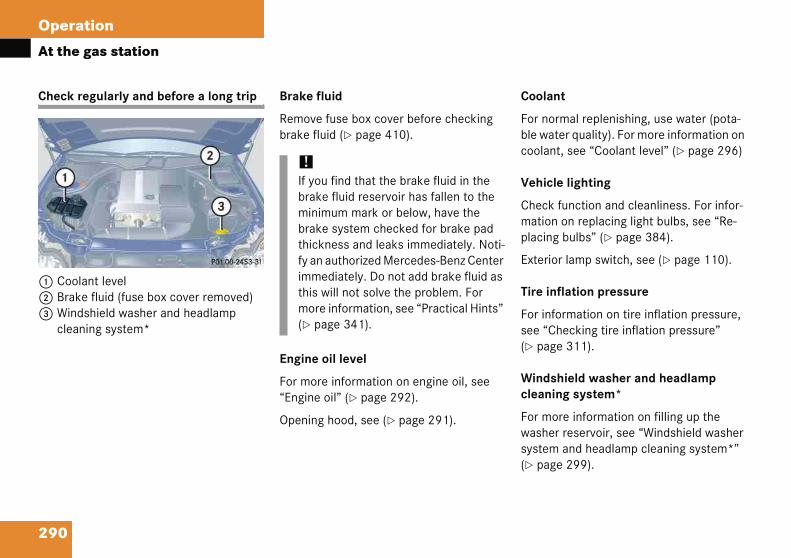
290
Operation
At the
Check r
1 Cool2 Brak3 Wind
clean
oolant
or normal replenishing, use water (pota-le water quality). For more information on oolant, see “Coolant level” (� page 296)
ehicle lighting
heck function and cleanliness. For infor-ation on replacing light bulbs, see “Re-
lacing bulbs” (� page 384).
xterior lamp switch, see (� page 110).
ire inflation pressure
or information on tire inflation pressure, ee “Checking tire inflation pressure”
page 311).
indshield washer and headlamp leaning system*
or more information on filling up the asher reservoir, see “Windshield washer ystem and headlamp cleaning system*”
page 299).
gas station
egularly and before a long trip
ant levele fluid (fuse box cover removed)shield washer and headlamp ing system*
Brake fluid
Remove fuse box cover before checking brake fluid (� page 410).
Engine oil level
For more information on engine oil, see “Engine oil” (� page 292).
Opening hood, see (� page 291).
C
Fbc
V
Cmp
E
T
Fs(�
Wc
Fws(�
!If you find that the brake fluid in the brake fluid reservoir has fallen to the minimum mark or below, have the brake system checked for brake pad thickness and leaks immediately. Noti-fy an authorized Mercedes-Benz Center immediately. Do not add brake fluid as this will not solve the problem. For more information, see “Practical Hints” (� page 341).

291
Operation
Engine compartment
�Ho
Op
Ththeda
1
� Pull handle 2 to its stop out of radiator grille.
� Pull up on the hood (do not pull up on the handle) and then release it.
The hood will be automatically held open at shoulder height by gas-filled struts.
W
Dcb
Warning! G
To help prevent personal injury, stay clear of moving parts when the hood is open and the engine is running. Make sure the hood is properly closed before driving. When closing the hood, use extreme caution not to catch hands or fingers.
The radiator fan may continue to run for ap-proximately 30 seconds or even restart af-ter the engine has been turned off. Stay clear of fan blades. ��
Enginod
ening
e hood left of
shboard
Hood
arning
o not pule is in me forced
e compartment
the hood
lock release lever is located to the steering wheel under the .
lock release lever
� Pull lever 1 downwards.
The hood is unlocked and handle 2 will extend out of the radiator grille.
2 Handle for opening the hood
! G
ll the release lever while the vehi-otion. Otherwise the hood could open by passing air flow.
!To avoid damage to the windshield wip-ers or hood, never open the hood if the wiper arms are folded forward away from the windshield.
292
Operation
Engine
ngine oil
he amount of oil your engine needs will epend on a number of factors, including riving style. Higher oil consumption can ccur when
the vehicle is new
the vehicle is driven frequently at higher engine speeds
ngine oil consumption checks should only e made after the vehicle break-in period.
Warni
If you sengine peraturoverheaaway fruntil thcall the
Warni
The engignitionit is dan(ignitiontic sock
� with
� whi
� if igturn
iDo not use any special lubricant addi-tives, as these may damage the drive assemblies. Using special additives not approved by Mercedes-Benz may cause damage not covered by the Mercedes-Benz Limited Warranty. More information on this subject is available at any Mercedes-Benz Center.
��
compartment
Closing the hood
� Let the hood drop from a height of approximately 1 ft (30 cm).
The hood will lock audibly.
� Check to make sure the hood is fully closed.
If you can raise the hood at a point above the headlamps, then it is not properly closed. Open it again and let it drop with somewhat greater force.
E
Tddo
�
�
Eb
ng! G
ee flames or smoke coming from the compartment, or if the coolant tem-e display indicates that the engine is ted, do not open the hood. Move
om vehicle and do not open the hood e engine has cooled. If necessary, fire department.
ng! G
ine is equipped with a transistorized system. Because of the high voltage gerous to touch any components coils, spark plug sockets, diagnos-et) of the ignition system
the engine running
le starting the engine
nition is “on” and the engine is ed manually
Warning! G
Be careful that you do not close the hood on anyone.
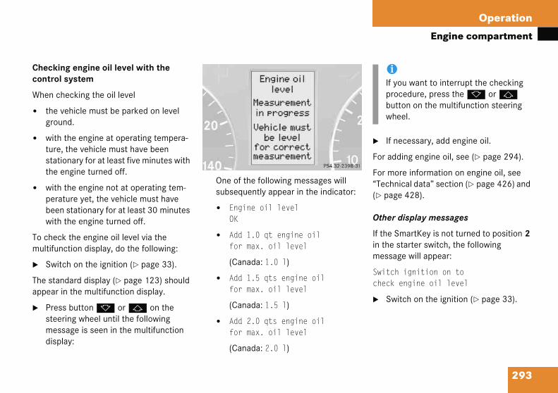
293
Operation
Engine compartment
Checkcontro
When c
� thegro
� witturstathe
� witperbeewit
To chemultifu
� Sw
The staappear
� Prestemedis
� If necessary, add engine oil.
For adding engine oil, see (� page 294).
For more information on engine oil, see “Technical data” section (� page 426) and (� page 428).
Other display messages
If the SmartKey is not turned to position 2 in the starter switch, the following message will appear:
Switch ignition on tocheck engine oil level
� Switch on the ignition (� page 33).
iIf you want to interrupt the checking procedure, press the k or j button on the multifunction steering wheel.
ing engine oil level with the l system
hecking the oil level
vehicle must be parked on level und.
h the engine at operating tempera-e, the vehicle must have been tionary for at least five minutes with engine turned off.
h the engine not at operating tem-ature yet, the vehicle must have n stationary for at least 30 minutes
h the engine turned off.
ck the engine oil level via the nction display, do the following:
itch on the ignition (� page 33).
ndard display (� page 123) should in the multifunction display.
ss button k or j on the ering wheel until the following ssage is seen in the multifunction play:
One of the following messages will subsequently appear in the indicator:
� Engine oil levelOK
� Add 1.0 qt engine oilfor max. oil level
(Canada: 1.0 l)
� Add 1.5 qts engine oilfor max. oil level
(Canada: 1.5 l)
� Add 2.0 qts engine oilfor max. oil level
(Canada: 2.0 l)
294
Operation
Engine
If you se
Observe
� If enwait chec
� If enture repe
If you se
Engine Not whe
� Turn
� If theture,oil.
� If theaturebefo
dding engine oil
!Only use approved engine oils and oil filters required for vehicles with Maintenance System (U.S. vehicles) or FSS (Canada vehicles). For a listing of approved engine oils and oil filters, refer to the Factory Approved Service Products pamphlet in your vehicle literature portfolio, or contact an authorized Mercedes-Benz Center.
Using engine oils and oil filters of spec-ification other than those expressly required for the Maintenance System (U.S. vehicles) or FSS (Canada vehi-cles), or changing of oil and oil filter at change intervals longer than those called for by the Maintenance System (U.S. vehicles) or FSS (Canada vehi-cles) will result in engine damage not covered by the Mercedes-Benz Limited Warranty.
compartment
e the message:
waiting time
gine is at operating temperature, five minutes before repeating k procedure.
gine is not at operating tempera-yet, wait 30 minutes before ating check procedure.
e the message:
oil leveln engine on
off the engine.
engine is at operating tempera- wait five minutes before checking
engine is not at operating temper- yet, you must wait 30 minutes
re checking oil.
If there is excess engine oil with the engine at normal operating temperature, the following message will appear:
Engine oil levelReduce oil level
� Have excess oil siphoned or drained off. Contact an authorized Mercedes-Benz Center.
For more information on messages in the display concerning engine oil, see “Practi-cal hints” (� page 363).
A
!Excess oil must be siphoned or drained off. It could cause damage to the engine and catalytic converter not covered by the Mercedes-Benz Limited Warranty.

295
Operation
Engine compartment
C 230 K
1 Fil
� Uns
� Addnot
Be careAvoid eenterin
Be careful not to spill any oil when adding. Avoid environmental damage caused by oil entering the ground or water.
� Screw filler cap 1 back on filler neck.
For more information on engine oil, see “Technical data” section (� page 426) and (� page 428).
!Excess oil must be siphoned or drained off. It could cause damage to the engine and catalytic converter not covered by the Mercedes-Benz Limited Warranty.
ompressor
ler cap
crew filler cap 1 from filler neck.
engine oil as required. Be careful to overfill with oil.
ful not to spill any oil when adding. nvironmental damage caused by oil g the ground or water.
� Screw filler cap 1 back on filler neck.
C 320
1 Filler cap
� Unscrew filler cap 1 from filler neck.
� Add engine oil as required. Be careful not to overfill with oil.
!Excess oil must be siphoned or drained off. It could cause damage to the engine and catalytic converter not covered by the Mercedes-Benz Limited Warranty.

296
Operation
Engine
Transm
The tranto be chfluid loshave an check th
� Using a rag, slowly open the cap approximately 1/2 turn to relieve ex-cess pressure. If opened immediately, scalding hot fluid and steam will be blown out under pressure.
� Do not spill antifreeze on hot engine parts. Antifreeze contains ethylene gly-col which may ignite and burn if it comes into contact with hot engine parts.
compartment
ission fluid level
smission fluid level does not need ecked. If you notice transmission s or gear shifting malfunctions, authorized Mercedes-Benz Center e transmission.
Coolant level
The engine coolant is a mixture of water and anticorrosion/antifreeze. To check the coolant level, the vehicle must be parked on level ground and the engine must be cool.
For more information on coolant, see “Coolants” (� page 432).
Warning! G
In order to avoid any possibly serious burns:
� Use extreme caution when opening the hood if there are any signs of steam or coolant leaking from the cooling system, or if the coolant temperature display indicates that the coolant is overheated.
� Do not remove pressure cap on coolant reservoir if coolant temperature is above 158°F (70°C). Allow engine to cool down before removing cap. The coolant reservoir contains hot fluid and is under pressure.

297
Operation
Engine compartment
The cothe pasment.
1 Coo2 Cap
Battery
Your vehicle’s battery is located in the en-gine compartment on the right hand side.
The battery should always be sufficiently charged in order to achieve its rated ser-vice life. Refer to Maintenance Booklet for battery maintenance intervals.
If you use your vehicle mostly for short-distance trips, you will need to have the battery charge checked more frequently.
When replacing the battery, always use batteries approved by Mercedes-Benz.
If you do not intend to operate your vehicle for an extended period of time, consult an authorized Mercedes-Benz Center about steps you need to observe.
olant expansion tank is located on senger side of the engine compart-
lant expansion tank
� Using a rag, turn the cap 2 slowly approximately one half turn counter-clockwise to release any excess pressure.
� Continue turning the cap counterclock-wise and remove it.
The coolant level is correct if the level
� for cold coolant: reaches the black top part of the reservoir
� for warm coolant: is approximately 0.6 in (1.5 cm) higher
� Add coolant as required.
� Replace and tighten cap.

298
Operation
Engine
G
A
D
B
compartment
Batteries contain materials that can harm the environment if disposed of improperly. Recycling of batteries is the preferred method of disposal. Many states require sellers of batteries to accept old batteries for recycling.
Observe all safety instructions and precautions when handling automotive batteries.
Risk of explosion.
Keep flames or sparks away from battery. Do not smoke.
Battery acid is caustic. Do not allow it to come into contact with skin, eyes or clothing.
In case it does, immediately flush affected area with clean water and seek medical help if necessary.
E Wear eye protection.
C Keep children away.
F Follow the instructions in this Operator’s Manual.
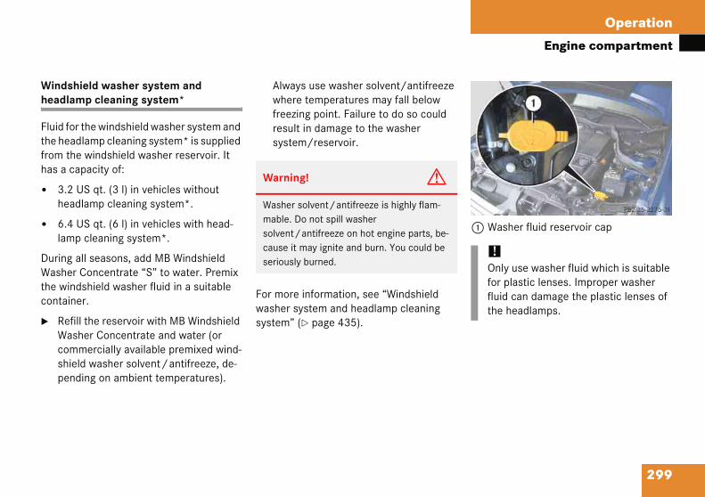
299
Operation
Engine compartment
Windsheadla
Fluid fothe heafrom thhas a c
� 3.2hea
� 6.4lam
DuringWashethe wincontain
� RefWacomshipen
1 Washer fluid reservoir cap
!Only use washer fluid which is suitable for plastic lenses. Improper washer fluid can damage the plastic lenses of the headlamps.
hield washer system and mp cleaning system*
r the windshield washer system and dlamp cleaning system* is supplied e windshield washer reservoir. It apacity of:
US qt. (3 l) in vehicles without dlamp cleaning system*.
US qt. (6 l) in vehicles with head-p cleaning system*.
all seasons, add MB Windshield r Concentrate “S” to water. Premix dshield washer fluid in a suitable er.
ill the reservoir with MB Windshield sher Concentrate and water (or mercially available premixed wind-
eld washer solvent/antifreeze, de-ding on ambient temperatures).
Always use washer solvent/antifreeze where temperatures may fall below freezing point. Failure to do so could result in damage to the washer system/reservoir.
For more information, see “Windshield washer system and headlamp cleaning system” (� page 435).
Warning! G
Washer solvent/antifreeze is highly flam-mable. Do not spill washer solvent/antifreeze on hot engine parts, be-cause it may ignite and burn. You could be seriously burned.

Operation
a
ar
mnt cs
portant guidelines
Only use sets of tires and rims of the same type and make.
Tires must be of the correct size for the rim.
Break in new tires for approximately 60 miles (100 km) at moderate speeds.
Regularly check the tires and rims for damage. Dented or bent rims can cause tire inflation pressure loss and damage to the tire beads.
If vehicle is heavily loaded, check tire inflation pressure and correct as required.
Do not allow your tires to wear down too far. Adhesion properties on wet roads are sharply reduced at tread depths under 1/8 in (3 mm).
When replacing individual tires, you should mount new tires on the front wheels first (on vehicles with same-sized wheels all around).
i
cea
aldf te
em
ed
300
Tires
See anfor inforecomand wiadvicepurcha
Warn
Replation, moriginMercetion. Imoun
� Thco
� Than
nd wheels
uthorized Mercedes-Benz Center mation on tested and ended rims and tires for summer er operation. They can also offer oncerning tire service and e.
Retreaded tires are not tested or recom-mended by Mercedes-Benz, since previous damage cannot always be recognized on retreads. The operating safety of the vehicle cannot be assured when such tires are used.
Im
�
�
�
�
�
�
�
ng! G
rims or tires with the same designa-nufacturer and type as shown on the part. See an authorized es-Benz Center for further informa-incorrectly sized rims and tires are d:
wheel brakes or suspension ponents can be damaged.
operating clearance of the wheels the tires may no longer be correct.
Warning! G
Worn, old tires can cause accidents. If the tire tread is badly worn, or if the tires have sustained damage, replace them.
When replacing rims, only use genuine Mercedes-Benz wheel bolts specified for the particular rim type. Failure to do so can result in the bolts loosening and possibly an accident.
301
Operation
Tires and wheels
Tire ca
Regulaat leastion onsee “Rsure” (
Life of tire
The service life of a tire is dependent upon varying factors including but not limited to:
� Driving style
� Tire inflation pressure
� Distance driven
Warn
Regulaged loss. Ayour v
Worn,tire trsustai
Warning! G
Tires and spare tire should be replaced after six years, regardless of the remaining tread.
re and maintenance
rly check your tire inflation pressure t once a month. For more informa- checking tire inflation pressure, ecommended tire inflation pres-� page 309).
Tire inspection
Every time you check your tire inflation pressure, you should also inspect your tires for the following:
� excessive treadwear (� page 302)
� cord or fabric showing through the tire’s rubber
� bumps, bulges, cuts, cracks or splits in the tread or side of the tire
Replace the tire if you find any of the above conditions.
Make sure you also inspect the spare tire periodically for condition and inflation. Spare tires will age and become worn over time even if never used, and thus should be inspected and replaced when necessary.
ing! G
arly check the tires for damage. Dam-tires can cause tire inflation pressure s a result, you could lose control of ehicle.
old tires can cause accidents. If the ead is badly worn, or if the tires have ned damage, replace them.
302
Operation
Tires a
Tread d
Do not afar. Adhsharply 1/8 in (3
Treadwelaw. Theplaces obecomeimately the tire replaced
Recomm
� Sum
� Wint
toring tires
leaning tires
Warni
Althouglaws cotreadweapproxirecomm
!Keep unmounted tires in a cool, dry place with as little exposure to light as possible. Protect tires from contact with oil, grease and gasoline.
!Never use a round nozzle to power wash tires. The intense jet of water can result in damage to the tire.
Always replace a damaged tire.
nd wheels
epth
llow your tires to wear down too esion properties on wet roads are reduced at tread depths under
mm).
ar indicators (TWI) are required by se indicators are located in six n the tread circumference and visible at a tread depth of approx-1/16 in (1.6 mm), at which point is considered worn and should be .
ended minimum tire tread depth:
mer tires 1/8 in (3 mm)
er tires 1/6 in (4 mm)
1 TWI (TreadWear Indicator)
The treadwear indicator appears as a solid band across the tread.
S
C
ng! G
h the applicable federal motor safety nsider a tire to be worn when the ar indicators (TWI) become visible at
mately 1/16 in (1.6 mm), we end that you do not allow your tires
to wear down to that level. As tread depth approaches 1/8 in (3 mm), the adhesion properties on a wet road are sharply reduced.
Depending upon the weather and/or road surface (conditions), the tire traction varies widely.
303
Operation
Tires and wheels
Direct
Unidiretages, mancemake sspecifi
An arrointendethe tire
� The Certification label, also found on the driver’s door B-pillar tells you about the gross weight capacity of your vehi-cle, called the Gross Vehicle Weight Rating (GVWR). The GVWR includes the weight of the vehicle, all occupants, fuel and cargo. The Certification label also tells you about the front and rear axle weight capacity, called the Gross Axle Weight Rating (GAWR). The GAWR is the total allowable weight that can be carried by a single axle (front or rear). Never exceed the GVWR or GAWR for either the front axle or rear axle.
iSpathewitusehasobsrarytion
ion of rotation
ctional tires offer added advan-such as better hydroplaning perfor-. To benefit, however, you must ure the tires rotate in the direction
ed.
w on the sidewall indicates the d direction of rotation (spinning) of .
Loading the vehicle
Two labels on your vehicle show how much weight it may properly carry.
� The Tire and Loading Information placard (Example A) or the Vehicle Tire Information placard (Example B) can be found on the driver’s door B-pillar. This placard tells you important information about the number of people that can be in the vehicle and the total weight that can be carried in the vehicle. It also contains information on the proper size and recommended tire inflation pressures for the original equipment tires on your vehicle.
re wheels may be mounted against direction of rotation (spinning) even h a unidirectional tire for temporary only until the regular drive wheel been repaired or replaced. Always erve and follow applicable tempo- use restrictions and speed limita-s indicated on the spare wheel.

304
Operation
Tires a
1 Drive
Followinwith theplacardsvehicle.
lacard (Example A)
Load limit information on the Tire and Loading Information placard
he placard showing the load limit informa-on is located on the driver’s door B-pillar. your vehicle is equipped with the Tire and oading Information placard (Example A), cate the statement “The combined eight of occupants and cargo should ever exceed XXX kilograms or XXX lbs.” n this placard. The combined weight of all ccupants, cargo/luggage and trailer ngue load (if applicable) should never
xceed the weight referenced in that tatement.
nd wheels
r’s door B-pillar
g is a discussion on how to work information contained on the two with regards to loading your
Tire and Loading Information
Your vehicle is equipped with either the Tire and Loading Information placard (Example A) or the Vehicle Tire Information placard (Example B).
P
1
TtiIfLlownootoes
Warning! G
Do not overload the tires by exceeding the specified load limit or vehicle capacity weight as indicated on the placard on the driver’s door B-pillar. Overloading the tires can overheat them, possibly causing a blowout. Overloading the tires can also result in handling or steering problems, or brake failure.
iData shown on placard examples is for illustration purposes only. Load limit data is specific to each vehicle and may vary from data shown in the illustra-tions below. Refer to placard on vehicle for actual data specific to your vehicle.

305
Operation
Tires and wheels
Placar
1 LoaTire
The plation is If your Tire Inflocate Weightweightand tranever evehicle
Placard (Example A)
1 Seating capacity
Placard (Example B)
1 Seating capacity
d (Example B)
d limit information on the Vehicle Information placard
card showing the load limit informa-located on the driver’s door B-pillar. vehicle is equipped with the Vehicle ormation placard (Example B), the heading “Vehicle Capacity ” on this placard. The combined of all occupants, cargo/luggage iler tongue (if applicable) should xceed the weight listed next to capacity weight.
Seating capacity
The seating capacity gives you important information on the number of occupants that can be in the vehicle. Observe front and rear seating capacity. Your vehicle is equipped with either placard Example A or placard Example B located on the driver’s door B-pillar (� page 304).
iData shown on placard examples is for illustration purposes only. Seating data is specific to each vehicle and may vary from data shown in the illustrations below. Refer to placard on vehicle for actual data specific to your vehicle.
306
Operation
Tires a
Steps fo
The folloas requir49, Cod575 purMotor V
Step 1 (Example
� Locaweigneveyour
Step 1 (Example
� LocaWeig
Step 2
� Detedriveridin
tep 6 (if applicable)
If your vehicle will be towing a trailer, load from your trailer will be trans-ferred to your vehicle. Consult this manual to determine how this reduces the available cargo and luggage load capacity of your vehicle (� page 308).
he following table shows examples on ow to calculate total and cargo load apacities with varying seating configura-ons and number and size of occupants. he following examples use a load limit f 1500 lbs. This is for illustration urposes only. Make sure you are using e actual load limit for your vehicle stated
n the vehicle’s placard (� page 304).
nd wheels
r determining correct load limit
wing steps have been developed ed of all manufacturers under Title
e of U.S. Federal Regulations, Part suant to the “National Traffic and ehicle Safety Act of 1966”.
Vehicles equipped with placard A)
te the statement “The combined ht of occupants and cargo should r exceed XXX kg or XXX lbs.” on vehicle’s placard.
Vehicles equipped with placard B)
te the heading “Vehicle Capacity ht” on your vehicle’s placard.
rmine the combined weight of the r and passengers that will be g in your vehicle.
Step 3
� Subtract the combined weight of the driver and passengers from XXX kilo-grams or XXX lbs.
Step 4
� The resulting figure equals the avail-able amount of cargo and luggage load capacity. For example, if the “XXX” amount equals 1400 lbs. and there will be five 150 lbs. passengers in your vehicle, the amount of available cargo and luggage load capacity is 650 lbs. (1400-750 (5 x150) = 650 lbs.)
Step 5
� Determine the combined weight of luggage and cargo being loaded on the vehicle. That weight may not safely exceed the available cargo and luggage load capacity calculated in step 4.
S
�
ThctiToptho
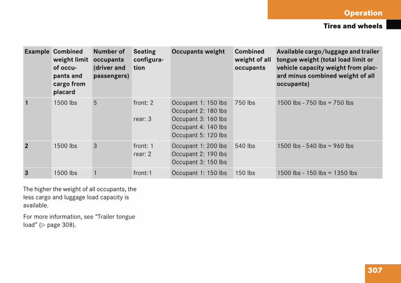
307
Operation
Tires and wheels
The higless caavailab
For moload” (
Examll
Available cargo/luggage and trailer tongue weight (total load limit or vehicle capacity weight from plac-ard minus combined weight of all occupants)
1 1500 lbs - 750 lbs = 750 lbs
2 1500 lbs - 540 lbs = 960 lbs
3 1500 lbs - 150 lbs = 1350 lbs
her the weight of all occupants, the rgo and luggage load capacity is le.
re information, see “Trailer tongue � page 308).
ple Combined weight limit of occu-pants and cargo from placard
Number of occupants (driver and passengers)
Seating configura-tion
Occupants weight Combined weight of aoccupants
1500 lbs 5 front: 2
rear: 3
Occupant 1: 150 lbsOccupant 2: 180 lbsOccupant 3: 160 lbsOccupant 4: 140 lbsOccupant 5: 120 lbs
750 lbs
1500 lbs 3 front: 1rear: 2
Occupant 1: 200 lbsOccupant 2: 190 lbsOccupant 3: 150 lbs
540 lbs
1500 lbs 1 front:1 Occupant 1: 150 lbs 150 lbs

308
Operation
Tires a
Certific
Even aftcombineand the (� pagesible loayour vehcle WeigAxle Wefront or GVWR abel. Theon the ddata” (�
railer tongue load
he tongue load of any trailer is an impor-nt weight to measure because it affects e load you can carry in your vehicle. If a ailer is towed, the tongue load must be dded to the weight of all occupants riding nd any cargo you are carrying in the ehicle. The tongue load typically is ten ercent of the trailer weight and every-ing loaded in it.
our Mercedes-Benz has been designed rimarily to carry passengers and their argo. Mercedes-Benz does not recom-end trailer towing with your vehicle.
nd wheels
ation label
er careful determination of the d weight of all occupants, cargo trailer tongue load (if applicable) 308) as to not exceed the permis-d limit, you must make sure that icle never exceeds the Gross Vehi-ht Rating (GVWR) and the Gross ight Rating (GAWR) for either the rear axle. You can obtain the nd GAWR from the Certification la- Certification Label can be found river’s door B-pillar, see “Technical page 416).
Gross Vehicle Weight Rating (GVWR): The total weight of the vehicle, all occupants, all cargo, and the trailer tongue load (� page 308) must never exceed the GVWR.
Gross Axle Weight Rating (GAWR): The to-tal allowable weight that can be carried by a single axle (front or rear).
To assure that your vehicle does not ex-ceed the maximum permissible weight limits (GVWR and GAWR for front and rear axle), have the loaded vehicle (including driver, passengers and all cargo and, if ap-plicable, trailer fully loaded) weighed on a suitable commercial scale.
T
Ttathtraavpth
Ypcm

309
Operation
Tires and wheels
Recom In addition to the tire placard on the driver’s door B-pillar, also consult the fuel filler flap for any additional information pertaining to special driving situations. For more information, see “Important notes on tire inflation pressure” (� page 310).
Warn
Followpress
Do nowear adverand aheate
Do nocan acomfodistan(blowobecomdebris
iData shown on placard examples is for illustration purposes only. Tire data is specific to each vehicle and may vary from data shown in the illustrations below. Refer to placard on vehicle for actual data specific to your vehicle.
mended tire inflation pressure Your vehicle is equipped with either the Tire and Loading Information placard (Example A) or the Vehicle Tire Information placard (Example B) located on the driver’s door B-pillar (� page 304).
The tire inflation pressure should be checked regularly and should only be ad-justed on cold tires. The tires can be con-sidered cold if the vehicle has been parked for at least three hours or driven less than one mile (1.6 km).
Follow recommended cold tire inflation pressures listed on placard.
Keeping the tires properly inflated provides the best handling, tread life and riding comfort.
ing! G
recommended tire inflation ures.
t underinflate tires. Underinflated tires excessively and/or unevenly, sely affect handling and fuel economy, re more likely to fail from being over-d.
t overinflate tires. Overinflated tires dversely affect handling and ride rt, wear unevenly, increase stopping ce, and result in sudden deflation ut) because they are more likely to e punctured or damaged by road , potholes etc.
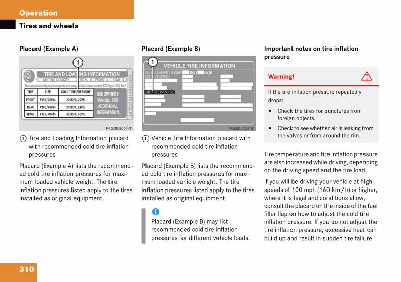
310
Operation
Tires a
Placard
1 Tire with pres
Placard ed cold mum loainflationinstalled
portant notes on tire inflation ressure
ire temperature and tire inflation pressure re also increased while driving, depending n the driving speed and the tire load.
you will be driving your vehicle at high peeds of 100 mph (160 km/h) or higher, here it is legal and conditions allow, onsult the placard on the inside of the fuel ller flap on how to adjust the cold tire flation pressure. If you do not adjust the re inflation pressure, excessive heat can uild up and result in sudden tire failure.
Warning! G
If the tire inflation pressure repeatedly drops:
� Check the tires for punctures from foreign objects.
� Check to see whether air is leaking from the valves or from around the rim.
nd wheels
(Example A)
and Loading Information placard recommended cold tire inflation sures
(Example A) lists the recommend-tire inflation pressures for maxi-ded vehicle weight. The tire pressures listed apply to the tires as original equipment.
Placard (Example B)
1 Vehicle Tire Information placard with recommended cold tire inflation pressures
Placard (Example B) lists the recommend-ed cold tire inflation pressures for maxi-mum loaded vehicle weight. The tire inflation pressures listed apply to the tires installed as original equipment.
Imp
Tao
Ifswcfiintib
iPlacard (Example B) may list recommended cold tire inflation pressures for different vehicle loads.

311
Operation
Tires and wheels
Be surepressushouldadjusti
Some vinflatioloads lvehicleprovidelocated
Tire infmatelyair temwhen cwhere the ou
Follow the steps below to achieve correct tire inflation pressure:
� Remove the cap from the valve on one tire.
� Firmly press a tire gauge onto the valve.
� Read tire inflation pressure on tire gauge and check against the recom-mended tire inflation pressure on the placard on the driver’s door B-pillar (� page 310). If necessary, add air to achieve the recommended tire inflation pressure. ��
to readjust the tire inflation re for normal driving speeds. You wait until the tires are cold before ng the tire inflation pressure.
ehicles may have supplemental tire n pressure information for vehicle ess than the maximum loaded condition. If such information is d, it can be found on the placard on the inside of the fuel filler flap.
lation pressure changes by approxi- 1.5 psi (0.1 bar) per 18°F (10°C) of perature change. Keep this in mind hecking tire inflation pressure the temperature is different from tside temperature.
Checking tire inflation pressure
Regularly check your tire inflation pressure at least once a month.
Check and adjust the tire inflation pressure when the tires are cold. The tires can be considered cold if the vehicle has been parked for at least three hours or driven less than one mile (1.6 km).
If you check the tire inflation pressure when the tires are warm (the vehicle has been driven for several miles or sitting less than three hours), the reading will be approximately 4 psi (0.3 bar) higher than the cold reading. This is normal. Do not let air out to match the specified cold tire inflation pressure. Otherwise, the tire will be underinflated.

312
Operation
Tires a
� Insta
� Repe
otential problems associated with nderinflated and overinflated tires
nderinflated tire inflation pressure
nderinflated tires can:
cause excessive and uneven tire wear
adversely affect fuel economy
lead to tire failure from being overheated
adversely affect handling characteristics
iIf youtire imetaa penpres
Warning! G
Follow recommended tire inflation pres-sures.
Do not underinflate tires. Underinflated tires wear excessively and/or unevenly, adversely affect handling and fuel economy, and are more likely to fail from being overheated.
��
nd wheels
ll the valve cap.
at this procedure for each tire.
Pu
U
U
�
�
�
�
have overfilled the tire, release nflation pressure by pushing the l stem of the valve with e.g. a tip of . Then recheck the tire inflation
sure with the tire gauge.
Warning! G
Follow recommended tire inflation pres-sures.
Do not underinflate tires. Underinflated tires wear excessively and/or unevenly, adversely affect handling and fuel economy, and are more likely to fail from being over-heated.
Do not overinflate tires. Overinflated tires can adversely affect handling and ride comfort, wear unevenly, increase stopping distance, and result in sudden deflation (blowout) because they are more likely to become punctured or damaged by road debris, potholes etc.
Do not overload the tires by exceeding the specified load limit or vehicle capacity weight as indicated on the placard on the driver’s door B-pillar. Overloading the tires can overheat them, possibly causing a blowout.

313
Operation
Tires and wheels
Overin
Overin
� advcha
� cau
� be haz
� adv
� inc
1 Uniform Quality Grading Standards (� page 320)
2 DOT, Tire Identification Number (TIN) (� page 318)
3 Maximum tire load (� page 319)4 Maximum tire inflation pressure
(� page 320)5 Manufacturer6 Tire ply material (� page 322)7 Tire size designation, load and speed
rating (� page 314)8 Load identification (� page 317)9 Tire name
Warn
Followpress
Do nocan acomfodistan(blowobecomdebris
iFor illustration purposes only. Actual data on tires is specific to each vehicle and may vary from data shown in above illustration.
For more information, see “Rims and Tires” (� page 419).
flated tire inflation pressure
flated tires can:
ersely affect handling racteristics
se uneven tire wear
more prone to damage from road ards
ersely affect ride comfort
rease stopping distance
Tire labeling
Besides tire name (sales designation) and manufacturer name, a number of markings can be found on a tire.
Following are some explanations for the markings on your vehicle’s tires:
ing! G
recommended tire inflation ures.
t overinflate tires. Overinflated tires dversely affect handling and ride rt, wear unevenly, increase stopping ce, and result in sudden deflation ut) because they are more likely to e punctured or damaged by road , potholes etc.

314
Operation
Tires a
Tire sizerating
1 Tire 2 Aspe3 Radi4 Rim 5 Tire 6 Tire
ire width
he tire width 1 (� page 314) indicates e nominal tire width in mm.
spect ratio
he aspect ratio 2 (� page 314) is the imensional relationship between tire ection height and section width and is xpressed in percentage. The aspect ratio arrived at by dividing section height by ection width.
ire code
he tire code 3 (� page 314) indicates e tire construction type. The “R” stands r radial tire type. Letter “D” means diag-
nal or bias ply construction; letter “B” eans belted-bias ply construction.
t the tire manufacturer’s option, any tire ith a speed capability above 149 mph 40 km/h) can include a “ZR” in the size
esignation (for example: 245/40 ZR 18). or additional information, see “Tire speed ting” (� page 316).
iFor idataand millust
nd wheels
designation, load and speed
width ct ratio in %al tire codediameterload ratingspeed rating
General:
Depending on the design standards used, the tire size molded into the sidewall may have no letter or a letter preceding the tire size designation.
No letter preceding the size designation (as illustrated above): Passenger car tire based on European design standards.
Letter “P” preceding the size designation: Passenger car tire based on U.S. design standards.
Letter “LT” preceding the size designation: Light Truck tire based on U.S. design standards.
Letter “T” preceding the size designation: Temporary spare tires which are high pressure compact spares designed for temporary emergency use only.
T
Tth
A
Tdseiss
T
Tthfoom
Aw(2dFra
llustration purposes only. Actual on tires is specific to each vehicle
ay vary from data shown in above ration.
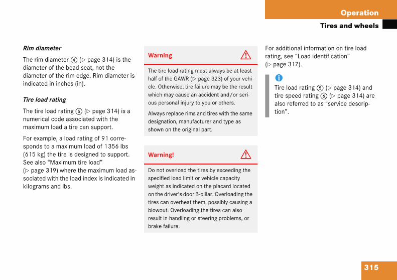
315
Operation
Tires and wheels
Rim di
The rimdiametdiametindicat
Tire lo
The tirnumermaxim
For exasponds(615 kSee als(� pagsociatekilogra
For additional information on tire load rating, see “Load identification” (� page 317).
iTire load rating 5 (� page 314) and tire speed rating 6 (� page 314) are also referred to as “service descrip-tion”.
ameter
diameter 4 (� page 314) is the er of the bead seat, not the er of the rim edge. Rim diameter is ed in inches (in).
ad rating
e load rating 5 (� page 314) is a ical code associated with the um load a tire can support.
mple, a load rating of 91 corre- to a maximum load of 1356 lbs
g) the tire is designed to support. o “Maximum tire load”
e 319) where the maximum load as-d with the load index is indicated in ms and lbs.
Warning G
The tire load rating must always be at least half of the GAWR (� page 323) of your vehi-cle. Otherwise, tire failure may be the result which may cause an accident and/or seri-ous personal injury to you or others.
Always replace rims and tires with the same designation, manufacturer and type as shown on the original part.
Warning! G
Do not overload the tires by exceeding the specified load limit or vehicle capacity weight as indicated on the placard located on the driver's door B-pillar. Overloading the tires can overheat them, possibly causing a blowout. Overloading the tires can also result in handling or steering problems, or brake failure.
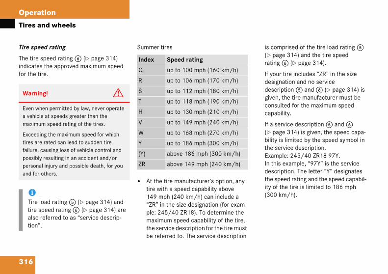
316
Operation
Tires a
Tire spe
The tire indicatefor the t
is comprised of the tire load rating 5 (� page 314) and the tire speed rating 6 (� page 314).
If your tire includes “ZR” in the size designation and no service description 5 and 6 (� page 314) is given, the tire manufacturer must be consulted for the maximum speed capability.
If a service description 5 and 6 (� page 314) is given, the speed capa-bility is limited by the speed symbol in the service description. Example: 245/40 ZR18 97Y. In this example, “97Y” is the service description. The letter “Y” designates the speed rating and the speed capabil-ity of the tire is limited to 186 mph (300 km/h).
Warni
Even wa vehicmaximu
Exceedtires arfailure, possiblpersonaand for
iTire tire salso tion”
nd wheels
ed rating
speed rating 6 (� page 314) s the approved maximum speed ire.
Summer tires
� At the tire manufacturer’s option, any tire with a speed capability above 149 mph (240 km/h) can include a “ZR” in the size designation (for exam-ple: 245/40 ZR18). To determine the maximum speed capability of the tire, the service description for the tire must be referred to. The service description
ng! G
hen permitted by law, never operate le at speeds greater than the m speed rating of the tires.
ing the maximum speed for which e rated can lead to sudden tire causing loss of vehicle control and y resulting in an accident and/or l injury and possible death, for you
others.
load rating 5 (� page 314) and peed rating 6 (� page 314) are referred to as “service descrip-.
Index Speed rating
Q up to 100 mph (160 km/h)
R up to 106 mph (170 km/h)
S up to 112 mph (180 km/h)
T up to 118 mph (190 km/h)
H up to 130 mph (210 km/h)
V up to 149 mph (240 km/h)
W up to 168 mph (270 km/h)
Y up to 186 mph (300 km/h)
(Y) above 186 mph (300 km/h)
ZR above 149 mph (240 km/h)
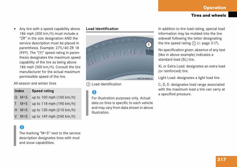
317
Operation
Tires and wheels
� Any186“ZRserpar(99thecap186maper
All-sea
In addition to tire load rating, special load information may be molded into the tire sidewall following the letter designating the tire speed rating 1 (� page 317).
No specification given: absence of any text (like in above example) indicates a standard load (SL) tire.
XL or Extra Load: designates an extra load (or reinforced) tire.
Light Load: designates a light load tire.
C, D, E: designates load range associated with the maximum load a tire can carry at a specified pressure.
Index
Q M+
T M+
H M+
V M+
iThedesand
tire with a speed capability above mph (300 km/h) must include a ” in the size designation AND the vice description must be placed in enthesis. Example: 275/40 ZR 18 Y). The “(Y)” speed rating in paren-sis designates the maximum speed ability of the tire as being above mph (300 km/h). Consult the tire
nufacturer for the actual maximum missible speed of the tire.
son and winter tires
Load identification
1 Load identification
Speed rating
S up to 100 mph (160 km/h)
S up to 118 mph (190 km/h)
S up to 130 mph (210 km/h)
S up to 149 mph (240 km/h)
marking “M+S” next to the service cription designates tires with mud snow capabilities.
iFor illustration purposes only. Actual data on tires is specific to each vehicle and may vary from data shown in above illustration.

318
Operation
Tires a
DOT, Tir
U.S. tiremanufacTIN intoproduce
The TIN tates effpurchassafety mpurchassuch tire
The TIN identificcode” an
OT (Department of Transportation)
tire branding symbol 1 (� page 318) hich denotes the tire meets require-ents of the U.S. Department of Transpor-tion.
anufacturer’s identification mark
he manufacturer’s identification mark 2 page 318) denotes the tire
anufacturer.
ew tires have a mark with two symbols.
etreaded tires have a mark with four sym-ols. For more information on retreaded res, see (� page 300).
ire size
he code 3 (� page 318) indicates the re size.
nd wheels
e Identification Number (TIN)
regulations require each new tire turer or tire retreader to mold a
or onto a sidewall of each tire d.
is a unique identifier which facili-orts by tire manufactures to notify ers in recall situations or other atters concerning tires and gives ers the means to easily identify s.
is comprised of “Manufacturer’s ation mark”, “Tire size”, “Tire type d “Date of manufacture”.
1 DOT 2 Manufacturer’s identification mark3 Tire size4 Tire type code (at the option of the tire
manufacturer)5 Date of manufacture
D
Awmta
M
T(�m
N
Rbti
T
Tti
iFor illustration purposes only. Actual data on tires is specific to each vehicle and may vary from data shown in above illustration.
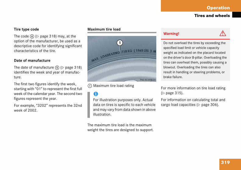
319
Operation
Tires and wheels
Tire ty
The cooptiondescripcharac
Date o
The daidentifiture.
The firsstartinweek ofigures
For exaweek o
For more information on tire load rating (� page 315).
For information on calculating total and cargo load capacities (� page 306).
Warning! G
Do not overload the tires by exceeding the specified load limit or vehicle capacity weight as indicated on the placard located on the driver’s door B-pillar. Overloading the tires can overheat them, possibly causing a blowout. Overloading the tires can also result in handling or steering problems, or brake failure.
pe code
de 4 (� page 318) may, at the of the manufacturer, be used as a tive code for identifying significant teristics of the tire.
f manufacture
te of manufacture 5 (� page 318) es the week and year of manufac-
t two figures identify the week, g with “01” to represent the first full f the calendar year. The second two represent the year.
mple, “3202” represents the 32nd f 2002.
Maximum tire load
1 Maximum tire load rating
The maximum tire load is the maximum weight the tires are designed to support.
iFor illustration purposes only. Actual data on tires is specific to each vehicle and may vary from data shown in above illustration.

320
Operation
Tires a
Maximu
1 Maxipres
This is thinflation
niform Tire Quality Grading Standards .S. vehicles)
ire manufacturers are required to grade res based on three performance ctors: treadwear, traction and mperature resistance.
TreadwearTractionTemperature resistance
iFor idataand millust
iFor illustration purposes only. Actual data on tires is specific to each vehicle and may vary from data shown in above illustration.
nd wheels
m tire inflation pressure
mum permissible tire inflation sure
e maximum permissible tire pressure for the tire.
Always follow the recommended tire inflation pressure (� page 309) for proper tire inflation.
U(U
Ttifate
123
llustration purposes only. Actual on tires is specific to each vehicle
ay vary from data shown in above ration.
Warning! G
Never exceed the max. tire inflation pressure. Follow recommended tire inflation pressures.
Do not underinflate tires. Underinflated tires wear excessively and/or unevenly, adverse-ly affect handling and fuel economy, and are more likely to fail from being overheated.
Do not overinflate tires. Overinflated tires can adversely affect handling and ride com-fort, wear unevenly, increase stopping dis-tance, and result in sudden deflation (blowout) because they are more likely to become punctured or damaged by road de-bris, potholes etc.
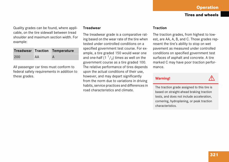
321
Operation
Tires and wheels
Qualitycable, shouldexamp
All pasfederathese g
Traction
The traction grades, from highest to low-est, are AA, A, B, and C. Those grades rep-resent the tire’s ability to stop on wet pavement as measured under controlled conditions on specified government test surfaces of asphalt and concrete. A tire marked C may have poor traction perfor-mance.
Tread
200
Warning! G
The traction grade assigned to this tire is based on straight-ahead braking traction tests, and does not include acceleration, cornering, hydroplaning, or peak traction characteristics.
grades can be found, where appli-on the tire sidewall between tread er and maximum section width. For le:
senger car tires must conform to l safety requirements in addition to rades.
Treadwear
The treadwear grade is a comparative rat-ing based on the wear rate of the tire when tested under controlled conditions on a specified government test course. For ex-ample, a tire graded 150 would wear one and one-half (1 1/2) times as well on the government course as a tire graded 100. The relative performance of tires depends upon the actual conditions of their use, however, and may depart significantly from the norm due to variations in driving habits, service practices and differences in road characteristics and climate.
wear Traction Temperature
AA A

322
Operation
Tires a
Temper
The temest), B, atance toability tocontrollelaboratoperatureto degencessive tire failulevel of car tirestor VehiGrades Bperformthan the
ire ply material
Plies in sidewallPlies under tread
his marking tells you about the type of ord and number of plies in the sidewall nd under the tread.
iFor illustration purposes only. Actual data on tires is specific to each vehicle and may vary from data shown in above illustration.
nd wheels
ature
perature grades are A (the high-nd C, representing the tire’s resis- the generation of heat and its dissipate heat when tested under d conditions on a specified indoor ry test wheel. Sustained high tem- can cause the material of the tire erate and reduce tire life, and ex-
temperature can lead to sudden re. The grade C corresponds to a performance which all passenger must meet under the Federal Mo-cle Safety Standard No. 109. and A represent higher levels of
ance on the laboratory test wheel minimum required by law.
T
12
Tca
Warning! G
The temperature grade for this tire is estab-lished for a tire that is properly inflated and not overloaded. Excessive speed, underin-flation, or excessive loading, either sepa-rately or in combination, can cause excessive heat build-up and possible tire failure.

323
Operation
Tires and wheels
Tire an
Acces
The costandaautompower seats, these ifactoryinstalle
Air pre
The amoutwarAir presquarebars.
Curb weight
The weight of a motor vehicle with standard equipment including the maxi-mum capacity of fuel, oil, and coolant, and, if so equipped, air conditioning and additional optional equipment, but without passengers and cargo.
DOT (Department of Transportation)
A tire branding symbol which denotes the tire meets requirements of the U.S. Department of Transportation.
GAWR (Gross Axle Weight Rating)
The GAWR is the maximum permissible axle weight. The gross vehicle weight on each axle must never exceed the GAWR for the front and rear axle indicated on the Certification label located on the driver's door B-pillar.
d loading terminology
sory weight
mbined weight (in excess of those rd items which may be replaced) of atic transmission, power steering, brakes, power windows, power radio, and heater, to the extent that tems are available as -installed equipment (whether d or not).
ssure
ount of air inside the tire pressing d on each square inch of the tire. ssure is expressed in pounds per inch (psi), or kilopascal (kPa) or
Aspect ratio
Dimensional relationship between tire section height and section width expressed in percentage.
Bar
Another metric unit for air pressure. There are 14.5038 pounds per square inch (psi) to 1 bar; there are 100 kilopascals (kPa) to 1 bar.
Bead
The tire bead contains steel wires wrapped by steel cords that hold the tire onto the rim.
Cold tire inflation pressure
Tire inflation pressure when your vehicle has been sitting for at least three hours or driven no more than one mile (1.6 km).
324
Operation
Tires a
GVW (G
The GVWvehicle iinstalledcargo anload. ThGWVR inlocated
GVWR (
This is thweight othe vehigers, fuetrailer toCertificadoor B-p
ormal occupant weight
he number of occupants the vehicle is esigned to seat, multiplied by 8 kilograms (150 lbs).
ccupant distribution
he distribution of occupants in a vehicle t their designated seating positions.
roduction options weight
he combined weight of those installed gular production options weighing over lbs (2.3 kilograms) in excess of those
tandard items which they replace, not reviously considered in curb weight or ccessory weight, including heavy duty rakes, ride levelers, roof rack, heavy duty attery, and special trim.
nd wheels
ross Vehicle Weight)
comprises the weight of the ncluding fuel, tools, spare wheel, accessories, passengers and d, if applicable, trailer tongue
e GWV must never exceed the dicated on the Certification label
on the driver's door B-pillar.
Gross Vehicle Weight Rating)
e maximum permissible vehicle f the fully loaded vehicle (weight of cle including all options, passen-l, and cargo and, if applicable, ngue load). It is indicated on tion label located on the driver’s illar.
Kilopascal (kPa)
The metric unit for air pressure. There are 6.9 kPa to one psi; another metric unit for air pressure is bars. There are 100 kilopascals (kPa) to one bar.
Maximum load rating
The maximum load in kilograms and pounds that can be carried by the tire.
Maximum loaded vehicle weight
The sum of curb weight, accessory weight, vehicle capacity weight and production options weight.
Maximum tire inflation pressure
This number is the greatest amount of air pressure that should ever be put in the tire under normal driving conditions.
N
Td6
O
Ta
P
Tre5spabb

325
Operation
Tires and wheels
PSI (Po
A stand-> bar,
Recom
Recomlisted oB-pillarProvideriding c
Rim
A metaassemseated
Sidew
The pothe bea
Tire speed rating
Part of tire designation; indicates the speed range for which a tire is approved.
Traction
Force exerted by the vehicle on the road via the tires. The amount of grip provided.
Tread
The portion of a tire that comes into contact with the road.
Treadwear indicators
Narrow bands, sometimes called “wear bars” that show across the tread of a tire when only 1/6 in (1.6 mm) of tread remains.
unds per square inch)
ard unit of measure for air pressure kilopascal (kPa).
mended tire inflation pressure
mended tire inflation pressure n placard located on driver's door for normal driving conditions. s best handling, tread life and omfort.
l support for a tire or a tire and tube bly upon which the tire beads are .
all
rtion of a tire between the tread and d.
TIN (Tire Identification Number)
Unique identifier which facilitates efforts by tire manufacturers to notify purchasers in recall situations or other safety matters concerning tires and gives purchases the means to easily identify such tires. The TIN is comprised of “Manufacturer’s identifica-tion mark”, “Tire size”, “Tire type code” and “Date of manufacture”.
Tire load rating
Numerical code associated with the maximum load a tire can support.
Tire ply composition and material used
This indicates the number of plies or the number of layers of rubber-coated fabric in the tire tread and sidewall. Tire manufac-turers also must indicate the ply materials in the tire and sidewall, which include steel, nylon, polyester, and others.
326
Operation
Tires a
Uniform
A tire inconsumtemperadetermingovernmratings atire.
Vehicle
Rated ca68 kilogdesignat
Vehicle
Load ondeterminshare ofweight a
applicable to your vehicle's tire configu-tion, tires can be rotated according to e tire manufacturer's recommended in-rvals in the tire manufacturer's warranty
amphlet located in your vehicle literature ortfolio. If none is available, tires should e rotated every 3000 to 6000 miles 000 to 10000 km), or sooner if neces-
ary, according to the degree of tire wear. he same rotation (spinning) direction ust be maintained (� page 303).
otate tires before the characteristic tire ear pattern becomes visible (shoulder ear on front tires and tread center wear n rear tires).
horoughly clean the mounting face of heels and brake disks, i.e. the inner side f the wheels/tires, during each rotation. heck for and ensure proper tire inflation ressure.
nd wheels
Tire Quality Grading Standards
formation system that provides ers with ratings for a tire's traction, ture and treadwear. Ratings are ed by tire manufacturers using ent testing procedures. The re molded into the sidewall of the
capacity weight
rgo and luggage load plus rams (150 lbs) times the vehicle's ed seating capacity.
maximum load on the tire
an individual tire that is ed by distributing to each axle its
the maximum loaded vehicle nd dividing it by two.
Rotating tires
Tire rotation can be performed on vehicles with tires of the same dimension all around. If your vehicle is equipped with tires of the same dimension all around, tires can be rotated, observing a a front-to-rear rotation pattern that will maintain the intended rotation (spinning) direction of the tire (� page 303).
In some cases, such as when your vehicle is equipped with mixed-size tires (different tire dimension front vs. rear), tire rotation is not possible.
Ifrathteppb(5sTm
Rwwo
TwoCp
Warning! G
Rotate front and rear wheels only if the tires are of the same dimension.
If your vehicle is equipped with mixed-size tires (different tire dimensions front vs. rear), tire rotation is not possible.

327
Operation
Tires and wheels
For inf“Practi(� pag
Warn
Have changloose 80 lb-
Only ubolts
ormation on wheel change, see the cal hints” section (� page 373) and e 394).
ing! G
the tightening torque checked after ing a wheel. Wheels could become if not tightened with a torque of ft (110 Nm).
se genuine Mercedes-Benz wheel specified for your vehicle’s rims.

Operation
r
t w
derv
cc
itean tve tepa
teh et a
nim ite
lways observe the speed rating of the inter tires installed on your vehicle. If the aximum speed for which your tires are ted is below the speed rating of your
ehicle, you must place a notice to this ffect where it will be seen by the driver. uch notices are available at your tire deal-r or any authorized Mercedes-Benz enter.
Warning! G
If you use your spare tire when winter tires are fitted on the other wheels, be aware that the difference in tire characteristics may very well impair turning stability and that overall driving stability may be reduced. Adapt your driving style accordingly.
Have the spare tire replaced with a winter tire at the nearest authorized Mercedes-Benz Center.
328
Winte
BeforevehicleMerceThis se
� Checon
� Addwacle“S”solfor(�
� BatwitA wthalow
� Tirememin1/6win
driving
he onset of winter, have your interized at an authorized s-Benz Center. ice includes:
k of anticorrosion and antifreeze entration.
tion of cleaning concentrate to the r of the windshield and headlamp ing system. Add MB Concentrate
o a premixed windshield washer nt/antifreeze which is formulated mperatures below freezing point ge 435).
ry test. Battery capacity drops decreasing ambient temperature. ll charged battery helps to ensure the engine can be started, even at mbient temperatures.
change. Mercedes-Benz recom-ds M+S rated radial-ply tires with a
um tread depth of approximately n (4 mm) on all four wheels for the r season.
Winter tires
Always use winter tires at temperatures below 45°F (7°C) and whenever wintry road conditions prevail. Use of winter tires is the only way to achieve the maximum effectiveness of the ABS and ESP in winter operation.
For safe handling, make sure that all mounted winter tires are of the same make and have the same tread design.
AwmraveSeC
Warning! G
Winter tires with a tread depth under 1/6 in (4 mm) must be replaced. They are no long-er suitable for winter operation.

329
Operation
Winter driving
Block
The enheater
The elean auth
Please observe the following guidelines when using snow chains:
� Use of snow chains is not permissible with all wheel/tire combinations.
� Snow chains should only be used on the rear wheels. Follow the manufac-turer's mounting instructions.
� Only use snow chains that are approved by Mercedes-Benz. An autho-rized Mercedes-Benz Center will be glad to advise you on this subject.
� Use of snow chains may be prohibited depending on location. Always check local and state laws before installing snow chains.
!Use of snow chains is not permissible with tire sizes:
� 245/40 R17
� 165 - 15 89P
� 165/70 - 16 92P
heater (Canada only)
gine is equipped with a block .
ctrical cable may be installed at orized Mercedes-Benz Center.
Snow chains
Snow chains should only be driven on snow-covered roads at speeds not to ex-ceed 30 mph (50 km/h). Remove chains as soon as possible when driving on roads without snow.
iWhen driving with snow chains, you may wish to deactivate the ESP (� page 83) before setting the vehicle in motion. This will improve the vehi-cle’s traction.

Operation
te
“Odin
onh
deinfoo
tai
at d
de
io i
iVehicles equipped with FSS (Flexible Service System) only (Canada vehicles): The interval between maintenance services depends on your driving habits. A gentle driving style, moderate engine speeds and the avoidance of short-distance trips will lengthen the interval between services.
330
Main
In the detailemainta
We stryour veMercethe Macalled indicat
Failureaccordand madesignvehicleMerce
The manotify yservice
nance
peration” section you will find information on operating, ing and caring for your vehicle.
gly recommend that you have icle serviced by an authorized s-Benz Center, in accordance with tenance Booklet at the times r by the maintenance service r display.
o have the vehicle maintained in nce with the Maintenance Booklet ntenance service indicator at the ed times/mileage will result in amage not covered by the s-Benz Limited Warranty.
ntenance service indicator will u when your next maintenance s due.
Starting approximately one month before your next maintenance service is due, one of the following messages will appear in the multifunction display while you are driving or when you switch on the ignition (example service A):
Service A in XX DaysService A in XX Miles (Km)A Service due now
The type of maintenance service due is indicated in the multifunction display:
9 Minor service (A)
´ Major service (B)

331
Operation
Maintenance
Clearinindica
The maautom
� aftetheten
� aftema
You ca
1 Res
� Preins
Calling up the maintenance service indicator
� Switch on the ignition (� page 33).
The standard display of the control system appears (� page 128).
� Press button k or j on the multifunction steering wheel until the maintenance service indicator with the service symbol 9 or ´ and the service deadline appears in the multifunction display.
iIf the battery is disconnected, the days of disconnection will not be included in the count shown by the maintenance service indicator. To arrive at the true maintenance service deadline, you will need to subtract these days from the days shown in the maintenance service indicator.
Do not confuse the maintenance service indicator with the engine oil level indicator :.
g the maintenance service tor
intenance service indicator is atically cleared
r ten seconds when you switch on ignition or when reaching the main-ance service threshold while driving
r 30 seconds, once the suggested intenance service term has passed
n also clear it yourself.
et button
ss reset button 1 on the trument cluster.
Maintenance service term exceeded
If you have exceeded the suggested maintenance service term, you will see the following message in the multifunction display:
Service A exceeded by XX DaysService A exceeded by XX Miles (Km)
In addition, a signal sounds when the message appears.
Any authorized Mercedes-Benz Center will reset the maintenance service indicator following a completed maintenance service.

332
Operation
Mainte
Resettinindicato
In the evon your authorizhave thereset. Thcarryingfind the maintenmaintenvehicle. either yoCenter o
nance
g the maintenance service r
ent that the maintenance service vehicle is not carried out by an ed Mercedes-Benz Center, you can maintenance service indicator e automotive maintenance facility out the maintenance service will information for resetting the ance service indicator in the ance-relevant information for your Such information is available from ur authorized Mercedes-Benz r directly from Mercedes-Benz.
iIf the maintenance service indicator was inadvertently reset, have an authorized Mercedes-Benz Center correct it.
Only reset if the proper maintenance service has been performed. Resetting the system without performing the proper service as called for by the maintenance service indicator will result in engine damage and/or other vehicle damage not covered by the Mercedes-Benz Limited Warranty.
333
Operation
Vehicle care
�Cl
Whveflutacun
More frequent washings are necessary to deal with unfavorable conditions:
� near the ocean
� in industrial areas (smoke, exhaust emissions)
� during winter operation
You should check your vehicle from time to time for stone chipping or other damage. Any damage should be repaired as soon as possible to prevent corrosion.
In doing so, do not neglect the underbody of the vehicle. A prerequisite for a thor-ough check is a washing of the underbody followed by a thorough inspection. Dam-aged areas need to be re-undercoated.
Your vehicle has been treated at the facto-ry with a wax-base rustproofing in the body cavities which will last for the lifetime of the vehicle. Post-production treatment is neither necessary nor recommended by Mercedes-Benz because of the possibility of incompatibility between materials used in the production process and others ap-plied later.
W
MSAud
Ns
Vehiceaning
ile in ohicle is ences wk the p
derbod
arning
any cleome arelways folar contoors or
ever usigned fo
le care and care of the vehicle
peration, even while parked, your subjected to varying external in-hich, if gone unchecked, can at-aintwork as well as the y and cause lasting damage.
Such damage is caused not only by ex-treme and varying climatic conditions, but also by:
� Air pollution
� Road salt
� Tar
� Gravel and stone chipping
To avoid paint damage, you should imme-diately remove:
� Grease and oil
� Fuel
� Coolant
� Brake fluid
� Bird droppings
� Insects
� Tree resins, etc.
Frequent washing reduces and/or elimi-nates the aggressiveness and potency of the above adverse influences.
! G
aning products can be hazardous. poisonous, others are flammable. llow the instructions on the partic-
ainer. Always open your vehicle’s windows when cleaning the inside.
e fluids or solvents that are not de-r cleaning your vehicle.
334
Operation
Vehicl
We havecompilespeciallywhich alYou cancar-careMercede
Scratchedamagecannot athe car-cIn such authoriz
The folloand care“how-toto Merceproducts
ar stains
uickly remove tar stains before they dry nd become more difficult to remove. A tar mover is recommended.
aintwork, painted body components
ercedes-Benz approved Paint Care hould be applied when water drops on the aint surface do not “bead up”, normally very three to five months, depending on limate and washing detergent used.
ercedes-Benz approved Paint Cleaner hould be applied if the paint surface hows signs of embedded dirt (i.e. loss of loss).
o not apply any of these products or wax your vehicle is parked in the sun or if the ood is still hot.
se the appropriate MB-Touch-Up Stick r quick and provisional repairs of minor
aint damage (i.e. chips from stones, ehicle doors, etc.).
e care
selected car-care products and d recommendations which are matched to our vehicles and ways reflect the latest technology. obtain Mercedes-Benz approved products at an authorized s-Benz Center.
s, corrosive deposits, corrosion or due to negligent or incorrect care lways be removed or repaired with are products recommended here.
cases it is best to seek aid at an ed Mercedes-Benz Center.
wing topics deal with the cleaning of your vehicle and give important
” information as well as references des-Benz approved car-care .
Power washer
When using a Power washer for cleaning the vehicle, always observe the manufac-turer’s operating instructions.
T
Qare
P
Mspec
Mssg
Difh
Ufopv
!Never use a round nozzle to power-wash tires. The intense jet of water can result in damage to the tire.
Always replace a damaged tire.
Always keep the jet of water moving across the surface. Do not aim directly at electrical parts, electrical connec-tors, seals, or other rubber parts.
335
Operation
Vehicle care
Engine
Prior tomake snents awater a
Corrosrosion gine cocleaninage bued. Thebe pro
Ornamental moldings
For regular cleaning and care of very dirty chrome-plated parts, use a chrome clean-er.
Headlamps, tail lamps, side markers, turn signal lenses
Use a mild car wash detergent, such as Mercedes-Benz approved Car Shampoo, with plenty of water.
To prevent scratches, never apply strong force and use only a soft, non-scratchy cloth when cleaning the lenses. Do not attempt to wipe dirty lenses with a dry cloth or sponge.
cleaning
cleaning the engine compartment ure to protect electrical compo-nd connectors from the intrusion of nd cleaning agents.
ion protection, such as MB Anticor-Wax, should be applied to the en-mpartment after every engine g. Before applying, all control link-shings and joints should be lubricat- poly-V-belt and all pulleys should
tected from any wax.
Vehicle washing
Do not use hot water or wash your vehicle in direct sunlight. Use only a mild car wash detergent, such as Mercedes-Benz ap-proved Car Shampoo.
Thoroughly spray the vehicle with a dif-fused jet of water. Direct only a very weak spray towards the ventilation intake. Use plenty of water and rinse the sponge and chamois frequently.
Rinse with clear water and thoroughly dry with a chamois. Do not allow cleaning agents to dry on the finish.
Due to the width of the vehicle, fold in ex-terior rear view mirrors prior to running the vehicle through an automatic car wash to prevent damage to the mirrors.
In the winter, thoroughly remove all traces of road salt as soon as possible.
When washing the underbody, do not forget to clean the inner sides of the wheels.

336
Operation
Vehicl
Wiper b
� Fold
� Cleaclean
ight alloy wheels
ercedes-Benz approved Wheel Care hould be used for regular cleaning of the ght alloy wheels.
possible, clean wheels once a week with ercedes-Benz approved Wheel Care, us-g a soft bristle brush and a strong spray f water.
ollow the instructions on container.
Warni
For saferemovebefore wise, thon and
!Fold ontoSma
Holdwipeof thsprin
iOnly use acid-free cleaning materials. Acid may cause corrosion or damage the clear coat.
e care
lades
wiper arms forward.
n the wiper blade inserts with a cloth and detergent solution.
Window cleaning
� Fold wiper arms forward.
� Use a window cleaning solution on all glass surfaces.
An automotive glass cleaner is recommended.
L
Msli
IfMino
F
ng! G
ty reasons, switch off wipers and SmartKey from starter switch cleaning the wiper blades. Other-e wiper motor could suddenly turn cause injury.
the windshield wiper arms back the windshield before turning the rtKey in the starter switch.
on to the wiper when folding the r arm back. If released, the force e impact from the tensioning g could crack the windshield.
Warning! G
For safety reasons, switch off wipers and remove SmartKey from starter switch before cleaning the windshield. Otherwise, the wiper motor could suddenly turn on and cause injury.
!Fold the windshield wiper arms back onto the windshield before turning the SmartKey in the starter switch.
Hold onto the wiper when folding the wiper arm back. If released, the force of the impact from the tensioning spring could crack the windshield.

337
Operation
Vehicle care
Instru
Use a gmild dewashinened inscourin
Steeri
Wipe wor cleaLeathe
Headliner
Clean with soft bristle brush, or use a dry-shampoo cleaner in case of excessive dirt.
Seat belts
The webbing must not be treated with chemical cleaning agents. Use only clear, lukewarm water and soap. Do not dry the webbing at temperatures above 176°F (80°C) or in direct sunlight.
Warning! G
Do not bleach or dye seat belts as this may severely weaken them. In a crash they may not be able to provide adequate protection.
ment cluster
entle dishwashing detergent or tergent for delicate fabrics as a g solution. Wipe with a cloth moist- lukewarm solution. Do not use g agents.
ng wheel and gear selector lever
ith a damp cloth and dry thoroughly n with Mercedes-Benz approved r Care.
Cup holders
Use a gentle dishwashing detergent or mild detergent for delicate fabrics as a washing solution. Wipe with a cloth moist-ened in lukewarm solution. Do not use scouring agents.
Hard plastic trim items
Pour Mercedes-Benz approved Interior Care onto soft lint-free cloth and apply with light pressure.
338
Operation
Vehicl
Upholst
Using afclothingcoloringthe uphocolored.intermedwill be p
Leather
Wipe leaand dry MercedeExerciseforated lbecome
ood trims
ampen cloth using water and use damp loth to clean wood trims in your vehicle. o not use solvents like tar remover or heel cleaner nor polishes or waxes as ese may be abrasive.
e care
ery
termarket seat covers or wearing that have the tendency to give off (e.g. when wet, etc.) may cause lstery to become permanently dis- By lining the seats with a proper iate cover, contact-discoloration
revented.
upholstery
ther upholstery with a damp cloth thoroughly or clean with s-Benz approved Leather Care. particular care when cleaning per-eather as its underside should not wet.
MB Tex upholstery
Pour Mercedes-Benz approved Interior Care onto soft lint-free cloth and apply with light pressure.
Plastic and rubber parts
Do not use oil or wax on these parts.
W
DcDwth

339
Practical hints
What to do if …
Where will I find ...?
Unlocking/locking in an emergency
Opening/closing in an emergency
Replacing SmartKey batteries
Replacing bulbs
Replacing wiper blades
Flat tire
Battery
Jump starting
Towing the vehicle
Fuses

Practical hints
t
ulb self-check when switching on the nition, have the respective bulb checked nd replaced if necessary.
m uggested solution
Continue driving with added caution. Wheels may lock during hard braking, reducing steering capability.
Read and observe messages in the display (� page 353).
Have the system checked at an autho-rized Mercedes-Benz Center as soon as possible.
ailure to follow these instructions ncreases the risk of an accident.
Switch off electrical consumers that are currently not needed, e.g. seat heating*.
If necessary, have the generator (alternator) and battery checked.
hen the voltage is above this value gain, the ABS is operational again.
340
What
Lamps
Proble
-
o do if …
in instrument cluster General information:If any of the following lamps in the instru-ment cluster fails to come on during the
biga
Possible cause S
The yellow ABS malfunction indicator lamp comes on while driving.
The ABS has detected a malfunction and has switched off. The BAS and the ESP are also switched off (see messages in display).
The brake system is still functioning normally but without the ABS available.
If the ABS control unit is malfunctioning, other systems such as the navigation system* or the automatic transmission* may also be malfunctioning.
�
�
�
Fi
The charging voltage has fallen below ten volts. The ABS has switched off.
The battery might not be charged sufficiently.
�
�
Wa

341
Practical hints
What to do if …
Proble Suggested solution
3
;
� Release the parking brake (� page 50).
� Risk of accident! Carefully stop the vehicle and notify an authorized Mercedes-Benz Center. Do not add brake fluid! This will not solve the problem.
Warn
Drivinnatedbrakebrakebrakesystemcan reenginfire. Y
m Possible cause
(Canada only)
(USA only)
The red brake warning lamp comes on while driving and you hear a warning sound.
You are driving with the parking brake set.
The red brake warning lamp comes on while driving.
There is insufficient brake fluid in the reservoir.
ing! G
g with the brake warning lamp illumi- can result in an accident. Have your system checked immediately if the warning lamp stays on. Don’t add fluid before checking the brake
. Overfilling the brake fluid reservoir sult in spilling brake fluid on hot
e parts and the brake fluid catching ou can be seriously burned.
!If you find that the brake fluid in the brake fluid reservoir has fallen to the minimum mark or below, have the brake system checked for brake pad thickness and leaks.

342
Practical hints
What t
Problem sted solution
ú
±
ve the vehicle checked as soon as possi- by an authorized Mercedes-Benz Center. on-board diagnostic connector is used the service station to link the vehicle to shop diagnostics system. It allows the urate identification of system lfunctions through the readout of gnostic trouble codes. It is located in the nt left area of the footwell next to the king brake pedal.
eck the fuel cap (� page 288).
not closed properly:
se the fuel cap.
closed properly:
ve the fuel system checked by an horized Mercedes-Benz Center.
er refuelling start, turn off and restart the ine three or four times in succession.
p-home mode is canceled. You do not o have your vehicle checked.
o do if …
Possible cause Sugge
(USA only)
(Canada only)
The yellow engine malfunction indicator lamp comes on while driving.
There is a malfunction in:
� The fuel management system
� The ignition system
� The emission control system
� Systems which affect emissions
Such malfunctions may result in ex-cessive emissions values and may switch the engine to its limp-home (emergency operation) mode.
� HableAnby theaccmadiafropar
A loss of pressure has been detect-ed in the fuel system. The fuel cap may not be closed properly or the fuel system may be leaky.
� Ch
If it is
� Clo
If it is
� Haaut
Your fuel tank is empty. � Afteng
The limneed t
343
Practical hints
What to do if …
Proble Suggested solution
v � Switch the ESP back on (� page 85).
If the ESP cannot be switched back on, have the system checked at an authorized Mercedes-Benz Center as soon as possible.
� When driving off, apply as little throttle as possible.
� While driving, ease up on the accelerator.
� Adapt your speed and driving to the prevailing road and weather conditions.
� Do not deactivate the ESP. Exceptions: (� page 83).
Failure to follow these instructions increases the risk of an accident.
m Possible cause
The yellow ESP warning lamp comes on while driving.
The ESP is deactivated.
Risk of accident!
Adapt your speed and driving to the prevailing road, weather and traffic conditions.
The yellow ESP warning lamp flashes while driving.
The ESP or traction control has come into operation because of detected traction loss in at least one tire.

344
Practical hints
What t
Problem uggested solution
Refuel at the next gas station (� page 288).
< Fasten your seat belt.
The telltale goes out.
Fasten the driver’s seat belt.
The telltale goes out.
1 Drive with added caution to the nearest authorized Mercedes-Benz Center.
Warni
In the eindicatenot be
which could result in serious or fatal injury, or it might deploy unexpectedly and unnec-essarily which could result in an accident and/or injury to you or to others.
o do if …
Possible cause S
The yellow fuel tank reserve warning lamp in the fuel gauge comes on while driving.
The fuel level has gone below the reserve mark.
�
The red seat belt telltale illumi-nates for a brief period after starting the engine.
The telltale reminds you and your passengers to fasten seat belts.
�
The red seat belt telltale illuminates and a warning chime sounds for approximately six seconds after starting the engine.
The driver’s seat belt is not fastened before the engine is started.
�
The red SRS indicator lamp comes on while driving.
There is a malfunction in the restraint systems. The air bags or emergency tensioning devices (ETDs) could deploy unexpectedly or fail to deploy in an accident.
�
ng! G
vent a malfunction of the SRS is d as outlined above, the SRS may
operational.
For your safety, we strongly recommend that you visit an authorized Mercedes-Benz Center immediately to have the system checked; otherwise the SRS may not be activated when needed in an accident,
345
Practical hints
What to do if …
Lamp
Proble ted solution
5 the system checked as soon as possible n authorized Mercedes-Benz Center.
note any messages in the multifunction lay and follow corrective steps age 347).
Warn
If the and retypicaindividnot hapasserepair
in center console
m Possible cause Sugges
6 The front passenger front air bag off indicator lamp illuminates and remains illuminated with the weight of a typical adult or some-one larger than a small individual on the front passenger seat.
The system is malfunctioning. � Haveby a
� Alsodisp(� p
ing! G
56 indicator lamp illuminates mains illuminated with the weight of a l adult or someone larger than a small ual on the front passenger seat, do ve any passenger use the front nger seat until the system has been ed.

346
Practical hints
What t
Problem lution
56 there is nothing between seat cushion eat and check installation of the child
that no objects applying supplemental o the seat are present.
passenger front air bag off indicator lamp t, have the system checked as soon as an authorized Mercedes-Benz Center. sport a child on the front passenger seat stem has been repaired.
ny messages in the multifunction display corrective steps (� page 349).
Warni
If the 5illuminaa typicachild reseat, dopassenrepaire
o do if …
Possible cause Suggested so
The front passenger front air bag off indicator lamp does not illuminate and/or does not remain illuminated with the weight of a typical 12-month-old child in a stan-dard child restraint or less on the front passenger seat.
The system is malfunctioning. � Make sureand child sseat.
� Make sureweight ont
� If the front remains oupossible byDo not tranuntil the sy
� Also note aand follow
ng! G
6 indicator lamp does not te or remains out with the weight of l 12-month-old child in a standard straint or less on the front passenger not transport a child on the front
ger seat until the system has been d.
347
Practical hints
What to do if …
Vehiclmultif
Warninappearin the i
Certaines are
Addresfollow this Op
Selectimemor(� pagunclea
High-pmultifu
Warning! G
All categories of messages contain important information which should be taken note of and, where a malfunction is indicated, addressed as soon as possible at an authorized Mercedes-Benz Center.
Failure to repair condition noted may cause damage not covered by the Mercedes-Benz Limited Warranty, or result in property damage or personal injury.
Warning! G
No messages will be displayed if either the instrument cluster or the multifunction display is inoperative.
Contact your nearest authorized Mercedes-Benz Center.
e status messages in the unction display
g and malfunction messages in the multifunction display located nstrument cluster.
warning and malfunction messag-accompanied by an audible signal.
s these messages accordingly and the additional instructions given in erator’s Manual.
ng the vehicle status message y menu in the control system e 132) displays both cleared and red messages.
riority messages appear in the nction display in red color.
Certain messages of high priority cannot be cleared from the multifunction display using the reset button (� page 24) or button j, k, ÿ, or è on the steering wheel.
Other messages of high priority and messages of less immediate priority can be cleared from the multifunction display using the reset button (� page 24) or button j, k, ÿ, or è on the steering wheel. These are then stored in the vehicle status message memory (� page 132). Remember that clearing a message will only make the message dis-appear. Clearing a message will not cor-rect the condition that caused the message to appear.
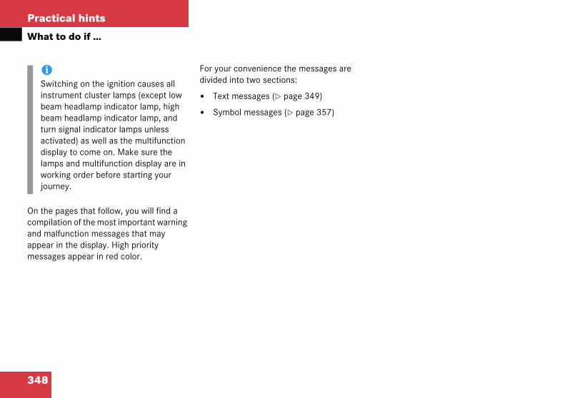
348
Practical hints
What t
On the pcompilaand malappear imessage
iSwitinstrbeambeamturn activdispllampworkjourn
o do if …
ages that follow, you will find a tion of the most important warning function messages that may n the display. High priority s appear in red color.
For your convenience the messages are divided into two sections:
� Text messages (� page 349)
� Symbol messages (� page 357)
ching on the ignition causes all ument cluster lamps (except low headlamp indicator lamp, high headlamp indicator lamp, and
signal indicator lamps unless ated) as well as the multifunction ay to come on. Make sure the s and multifunction display are in ing order before starting your ey.

349
Practical hints
What to do if …
Text m
Displa Possible solution
Stop the vehicle in a safe location as soon as possible and check the following:
� Make sure that there is nothing between seat cushion and child seat and check installation of the child seat.
� Make sure that no objects applying supplemental weight onto the seat are present. The system may recognize such supplemental weight and sense that an occupant on the front passen-ger seat is of a heavier weight than ac-tually present.
(Continued on next page)
essages
y message Possible cause
Front-passairbag activatedSee Operator’s Manual
Air bag is activated while driving even though a child, small individual, or object below the system's weight threshold is on the front passenger seat, or the front pas-senger seat is empty. Objects on the seat or forces acting on the seat may make the system sense supplemental weight.

350
Practical hints
What t
Display solution
ing any of the above corrective steps is ul, the message Front-pass airbag ted See Operator’s Manual will appear
ultifunction display, confirming the situa-been remedied. Note that after perform-orrective steps, it may take up to ds for the message Front-pass airbag ted See Operator’s Manual to appear.
ssage Front-pass airbag activated ator’s Manual remains on in the multi-
display and/or the 56 indicator ains out even after performing the rrective steps, have the system checked as possible by an authorized s-Benz Center.
Warni
If the mactivamains othe 5
o do if …
message Possible cause Possible
Front-passairbag activatedSee Operator’s Manual
If performsuccessfdeactivain the mtion has ing the c60 secondeactiva
If the meSee Operfunctionlamp remabove coas soon Mercede
ng! G
essage Front-pass airbag ted See Operator’s Manual re-n in the multifunction display and/or
6 indicator lamp remains out
even after performing the above corrective steps, do not have any children12 years old and under and other small individuals use the front passenger seat until the system has been repaired.

351
Practical hints
What to do if …
Displa olution
hicle in a safe location as soon as possi-eck the following:
lean on armrests or lift yourself up using over the door. This may make the system hat an occupant of a lesser weight than present is on the front passenger seat.
ition yourself.
erly belted in a nearly upright position ur back against the seat backrest.
ng any of the above corrective steps is , the message Front-pass airbag See Operator’s Manual will appear in the on display, confirming the situation has died.
on next page)
y message Possible cause Possible s
Front-passairbag deactivatedSee Operator’s Manual
Air bag is deactivated while driv-ing even though an adult or some-one larger than a small individual is occupying the front passenger seat. Forces acting on the seat may make the system sense a decrease in weight.
Stop the veble and ch
� Do nothandle sense tactually
� Re-pos
� Sit propwith yo
If performisuccessfulactivatedmultifunctibeen reme
(Continued

352
Practical hints
What t
Display lution
ter performing the corrective steps, it to 60 seconds for the message airbag activated See Operator’s
ppear.
ge Front-pass airbag deactivated See Manual remains on in the multifunction or the 56 indicator lamp re-
en after performing the above corrective the system checked as soon as possible rized Mercedes-Benz Center.
any passenger use the front passenger e system has been repaired.
Warni
If the mdeactiremainsand/ormains iabove csenger the sys
o do if …
message Possible cause Possible so
Front-passairbag deactivatedSee Operator’s Manual
Note that afmay take upFront-pass Manual to a
If the messaOperator’s display and/mains on evsteps, have by an autho
Do not haveseat until th
ng! G
essage Front-pass airbag vated See Operator’s Manual on in the multifunction display
the 56 indicator lamp re-lluminated even after performing the orrective steps, do not have any pas-use the front passenger seat until tem has been repaired.

353
Practical hints
What to do if …
Displa Possible solution
ABS � Continue driving with added caution. Wheels may lock during hard braking, reducing steering capability.
� Have the system checked at an authorized Mercedes-Benz Center as soon as possible.
Failure to follow these instructions increases the risk of an accident.
� Continue driving with added caution. Wheels may lock during hard braking, reducing steering capability.
� Have the system checked at an authorized Mercedes-Benz Center as soon as possible.
Failure to follow these instructions increases the risk of an accident.
y message Possible cause
malfunction.Visit workshop.
The ABS has detected a malfunction and has switched off. The ESP and the BAS are also deactivated.
The brake system is still functioning normally but without the ABS available.
Display malfunction.Visit workshop.
The ABS or the ABS display is malfunctioning.

354
Practical hints
What t
Display ossible solution
BAS Continue driving with added caution.
If necessary, have the generator and battery checked.
hen the voltage is above this value gain, the BAS is operational again.
Continue driving with added caution.
Have the system checked at an authorized Mercedes-Benz Center as soon as possible.
ailure to follow these instructions creases the risk of an accident.
Continue driving with added caution.
Have the system checked at an authorized Mercedes-Benz Center as soon as possible.
ailure to follow these instructions creases the risk of an accident.
o do if …
message Possible cause P
unavailableSee Operator’s Manual
The charging voltage has fallen below ten volts. The BAS has switched off.The battery might not be charged sufficiently.
The brake system is still functioning normally but without the BAS available.
�
�
Wa
malfunction.Visit workshop.
The BAS has detected a malfunction and switched off.
�
�
Fin
Display malfunction.Visit workshop.
The BAS or the BAS display is malfunctioning.
�
�
Fin

355
Practical hints
What to do if …
Displa Possible solution
ESP � Continue driving with added caution.
� Visit an authorized Mercedes-Benz Center as soon as possible.
Failure to follow these instructions increases the risk of an accident.
As soon as the brakes have cooled off, the electronic traction system switches on again.
The display will clear after driving a short distance at more than 12 mph (20 km/h).
� Continue driving with added caution.
� If necessary, have the generator and battery checked.
When the voltage is above this value again, the ESP is operational again.
y message Possible cause
unavailableSee Operator’s Manual
The ESP was deactivated because of a malfunction or interrupted power supply.
The ABS might not be operational.
The brake system is still functioning normally but without the ESP available.
If the yellow ESP warning lamp v flashes while driving and this message appears, the electronic traction system has switched off to prevent overheating of the drive wheel brakes.
The self-diagnosis has not been completed yet.
The brake system is still functioning normally but without the ESP available.
The charging voltage has fallen below ten volts. The ESP has switched off.
The battery might not be charged sufficiently.
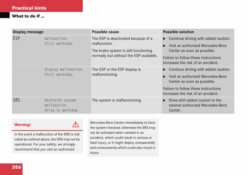
356
Practical hints
What t
Display ossible solution
ESP Continue driving with added caution.
Visit an authorized Mercedes-Benz Center as soon as possible.
ailure to follow these instructions creases the risk of an accident.
Continue driving with added caution.
Visit an authorized Mercedes-Benz Center as soon as possible.
ailure to follow these instructions creases the risk of an accident.
SRS Drive with added caution to the nearest authorized Mercedes-Benz Center.
Warni
In the ecated aoperatirecomm
o do if …
message Possible cause P
malfunction.Visit workshop.
The ESP is deactivated because of a malfunction.
The brake system is still functioning normally but without the ESP available.
�
�
Fin
Display malfunction.Visit workshop.
The ESP or the ESP display is malfunctioning.
�
�
Fin
Restraint systemmalfunctionDrive to workshop
The system is malfunctioning. �
ng! G
vent a malfunction of the SRS is indi-s outlined above, the SRS may not be onal. For your safety, we strongly end that you visit an authorized
Mercedes-Benz Center immediately to have the system checked; otherwise the SRS may not be activated when needed in an accident, which could result in serious or fatal injury, or it might deploy unexpectedly and unnecessarily which could also result in injury.
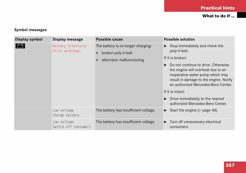
357
Practical hints
What to do if …
Symbo
Displa Possible solution
# � Stop immediately and check the poly-V-belt.
If it is broken:
� Do not continue to drive. Otherwise the engine will overheat due to an inoperative water pump which may result in damage to the engine. Notify an authorized Mercedes-Benz Center.
If it is intact:
� Drive immediately to the nearest authorized Mercedes-Benz Center.
� Start the engine (� page 48).
� Turn off unnecessary electrical consumers
l messages
y symbol Display message Possible cause
Battery AlternatorVisit workshop.
The battery is no longer charging:
� broken poly-V-belt
� alternator malfunctioning
Low voltageCharge battery
The battery has insufficient voltage.
Low voltageSwitch off consumers
The battery has insufficient voltage.
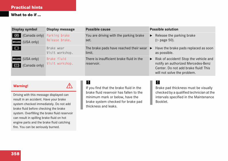
358
Practical hints
What t
Display ossible solution
! (
; (
Release the parking brake (� page 50).
2 Have the brake pads replaced as soon as possible.
; (
3 (
Risk of accident! Stop the vehicle and notify an authorized Mercedes-Benz Center. Do not add brake fluid! This will not solve the problem.
Warni
Drivingresult insystembrake fsystemcan resengine fire. Yo
!Brake pad thickness must be visually checked by a qualified technician at the intervals specified in the Maintenance Booklet.
o do if …
symbol Display message Possible cause P
Canada only)
USA only)
Parking brakeRelease brake.
You are driving with the parking brake set.
�
Brake wearVisit workshop.
The brake pads have reached their wear limit.
�
USA only)
Canada only)
Brake fluidVisit workshop.
There is insufficient brake fluid in the reservoir.
�
ng! G
with this message displayed can an accident. Have your brake
checked immediately. Do not add luid before checking the brake . Overfilling the brake fluid reservoir ult in spilling brake fluid on hot parts and the brake fluid catching u can be seriously burned.
!If you find that the brake fluid in the brake fluid reservoir has fallen to the minimum mark or below, have the brake system checked for brake pad thickness and leaks.

359
Practical hints
What to do if …
Displa Possible solution
B � Add coolant (� page 296).
� If you have to add coolant frequently, have the cooling system checked by an authorized Mercedes-Benz Center.
Warn
Do noAntifrmay bengin
y symbol Display message Possible cause
CoolantCheck level
The coolant level is too low.
ing! G
t spill antifreeze on hot engine parts. eeze contains ethylene glycol which urn if it comes into contact with hot e parts. You can be seriously burned.
!Do not ignore the low engine coolant level warning. Extended driving with the message and symbol displayed may cause serious engine damage not covered by the Mercedes-Benz Limited Warranty.
Do not drive without sufficient amount of coolant in the cooling system. The engine will overheat causing major engine damage.

360
Practical hints
What t
Display ossible solution
• Stop the vehicle and turn off the engine.
Only start the engine again after the message disappears. You could otherwise damage the engine.
Warni
Drivingheated have leacatch fi
Steam fseriousthe hoosee or h
Turn ofand do engine
!The engine should not be operated with the coolant temperature above 248°F (120°C). Doing so may cause serious engine damage which is not covered by the Mercedes-Benz Limited Warranty.
o do if …
During severe operating conditions and stop-and-go city traffic, the coolant tem-perature may rise close to 248°F (120°C).
symbol Display message Possible cause P
CoolantStop, engine off!
The coolant is too hot. �
�
ng! G
when your engine is badly over-can cause some fluids which may ked into the engine compartment to
re. You could be seriously burned.
rom an overheated engine can cause burns and can occur just by opening d. Stay away from the engine if you ear steam coming from it.
f the engine, get out of the vehicle not stand near the vehicle until the has cooled down.

361
Practical hints
What to do if …
Displa ssible solution
• Stop immediately and check the poly-V-belt.
it is broken:
Do not continue to drive. Otherwise the engine will overheat due to an inoperative water pump which may result in damage to the engine. Notify an authorized Mercedes-Benz Center.
it is intact:
Do not continue to drive the vehicle with this message displayed. Doing so could result in serious engine damage that is not covered by the Mercedes-Benz Limited Warranty.
Observe the coolant temperature gauge (� page 24).
Drive immediately to the nearest authorized Mercedes-Benz Center.
Observe the coolant temperature gauge.
Have the fan replaced as soon as possible.
y symbol Display message Possible cause Po
CoolantStop, engine off!
The poly-V-belt could be broken. �
If
�
If
�
�
�
CoolantVisit workshop.
The cooling fan for the coolant is malfunctioning.
�
�

362
Practical hints
What t
Display ossible solution
Ñ Visit an authorized Mercedes-Benz Center.
G Continue driving with added caution.
Visit an authorized Mercedes-Benz Center as soon as possible.
Have the electronic systems checked by an authorized Mercedes-Benz Center.
± Have the electronic systems checked by an authorized Mercedes-Benz Center.
J Close the doors.
o do if …
symbol Display message Possible cause P
Cruise contr.Drive to workshop
Cruise control is malfunctioning. �
Display malfunction.Visit workshop.
The instrument cluster display is malfunctioning.
�
�
The displays for several systems have malfunctioned. Some systems them-selves may also have malfunctioned.
�
Display malfunction.Visit workshop.
Certain electronic systems are unable to relay information to the control system. The following systems may have failed:
� Coolant temperature display
� Tachometer
� Cruise control display
�
Doors open You are attempting to drive with one or more doors open.
�

363
Practical hints
What to do if …
Displa Possible solution
: � Add engine oil (� page 294) and check the engine oil level (� page 293).
� Carefully bring the vehicle to a halt as soon as possible.
� Turn off the engine.
� Add engine oil (� page 294) and check the engine oil level (� page 293).
� Have oil siphoned or drained off. Observe all legal requirements with respect to its disposal.
� Have the engine oil checked.
y symbol Display messages Possible cause
USA only:At next gas stationadd 1.0 qt engine oil
Canada only:At next gas stationadd 1.0 l engine oil
The engine oil level is too low.
Engine oil levelStop, engine off!
There is no oil in the engine. There is a danger of engine damage.
Engine oil levelReduce oil level
You have added too much engine oil. There is a risk of damaging the engine or the catalytic converter.
Change engine oilVisit workshop.
It may be that there is water in the engine oil.

364
Practical hints
What t
When thadd 1.0appearsoperatinhas dropmum lev
Display ossible solution
: Check the engine oil level (� page 294) and add oil as required (� page 293).
If you must add engine oil frequently, have the engine checked for possible leaks.
Have the measuring system checked by an authorized Mercedes-Benz Center.
!The engine oil level warnings should not be ignored. Extended driving with the symbol displayed could result in serious engine damage that is not covered by the Mercedes-Benz Limited Warranty.
o do if …
e message At next gas station qt engine oil (Canada: 1.0 l)
while the engine is running and at g temperature, the engine oil level ped to approximately the mini-el.
When this occurs, the warning will first come on intermittently and then stay on if the oil level drops further.
Visually check for oil leaks. If no obvious oil leaks are noted, drive to the nearest service station where the engine oil should be topped to the required level with an approved oil specified in the Factory Approved Service Products pamphlet.
symbol Display messages Possible cause P
Engine oil levelVisit workshop.
The engine oil has dropped to a critical level.
�
�
Oil sensor malfunctionVisit workshop.
The measuring system is malfunctioning. �
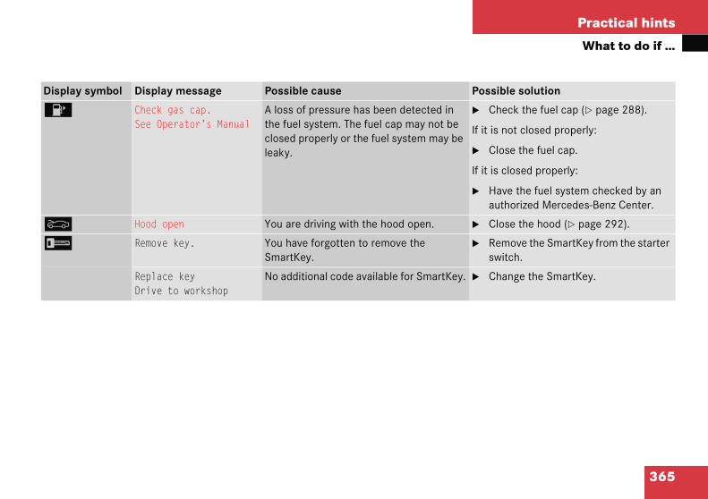
365
Practical hints
What to do if …
Displa Possible solution
4 � Check the fuel cap (� page 288).
If it is not closed properly:
� Close the fuel cap.
If it is closed properly:
� Have the fuel system checked by an authorized Mercedes-Benz Center.
Y � Close the hood (� page 292).
I � Remove the SmartKey from the starter switch.
� Change the SmartKey.
y symbol Display message Possible cause
Check gas cap.See Operator’s Manual
A loss of pressure has been detected in the fuel system. The fuel cap may not be closed properly or the fuel system may be leaky.
Hood open You are driving with the hood open.
Remove key. You have forgotten to remove the SmartKey.
Replace keyDrive to workshop
No additional code available for SmartKey.

366
Practical hints
What t
Display ossible solution
. Visit an authorized Mercedes-Benz Center as soon as possible.
Replace the bulb as soon as possible.
Replace the bulb as soon as possible.
Visit an authorized Mercedes-Benz Center as soon as possible.
Replace the bulb as soon as possible.
Replace the bulb as soon as possible.
Visit an authorized Mercedes-Benz Center as soon as possible.
Visit an authorized Mercedes-Benz Center as soon as possible.
Visit an authorized Mercedes-Benz Center as soon as possible.
Replace the bulb as soon as possible.
Replace the bulb as soon as possible.
o do if …
symbol Display message Possible cause P
3rd brake lamp The high mounted brake lamp is malfunctioning. This message will only appear if all LEDs have stopped working.
�
Backup lamp, left The left backup lamp is malfunctioning. �
Backup lamp, right The right backup lamp is malfunctioning. �
Brake lampDrive to workshop
Brake lamp illumination is delayed or lamp is permanently on.
�
Brake lamp left The left brake lamp is malfunctioning. �
Brake lamp right The right brake lamp is malfunctioning. �
Display malfunction.Visit workshop
The display for the lamps or the system is malfunctioning.
�
Front foglamp left The left front fog lamp is malfunctioning. �
Front foglamp right The right front fog lamp is malfunctioning. �
Front leftside marker lamp
The left front side marker lamp is malfunctioning.
�
Front right side marker lamp
The right front side marker lamp is malfunctioning.
�
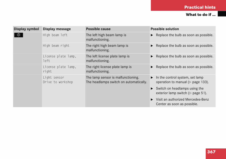
367
Practical hints
What to do if …
Displa Possible solution
. � Replace the bulb as soon as possible.
� Replace the bulb as soon as possible.
� Replace the bulb as soon as possible.
� Replace the bulb as soon as possible.
� In the control system, set lamp operation to manual (� page 133).
� Switch on headlamps using the exterior lamp switch (� page 51).
� Visit an authorized Mercedes-Benz Center as soon as possible.
y symbol Display message Possible cause
High beam left The left high beam lamp is malfunctioning.
High beam right The right high beam lamp is malfunctioning.
License plate lamp,left
The left license plate lamp is malfunctioning.
License plate lamp,right
The right license plate lamp is malfunctioning.
Light sensorDrive to workshop
The lamp sensor is malfunctioning. The headlamps switch on automatically.
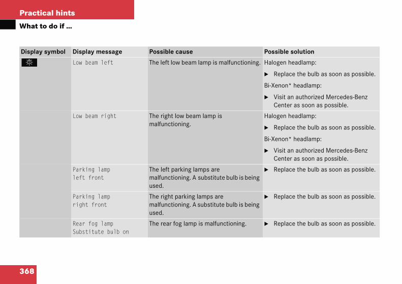
368
Practical hints
What t
Display ossible solution
. alogen headlamp:
Replace the bulb as soon as possible.
i-Xenon* headlamp:
Visit an authorized Mercedes-Benz Center as soon as possible.
alogen headlamp:
Replace the bulb as soon as possible.
i-Xenon* headlamp:
Visit an authorized Mercedes-Benz Center as soon as possible.
Replace the bulb as soon as possible.
Replace the bulb as soon as possible.
Replace the bulb as soon as possible.
o do if …
symbol Display message Possible cause P
Low beam left The left low beam lamp is malfunctioning. H
�
B
�
Low beam right The right low beam lamp is malfunctioning.
H
�
B
�
Parking lamp left front
The left parking lamps are malfunctioning. A substitute bulb is being used.
�
Parking lamp right front
The right parking lamps are malfunctioning. A substitute bulb is being used.
�
Rear fog lampSubstitute bulb on
The rear fog lamp is malfunctioning. �
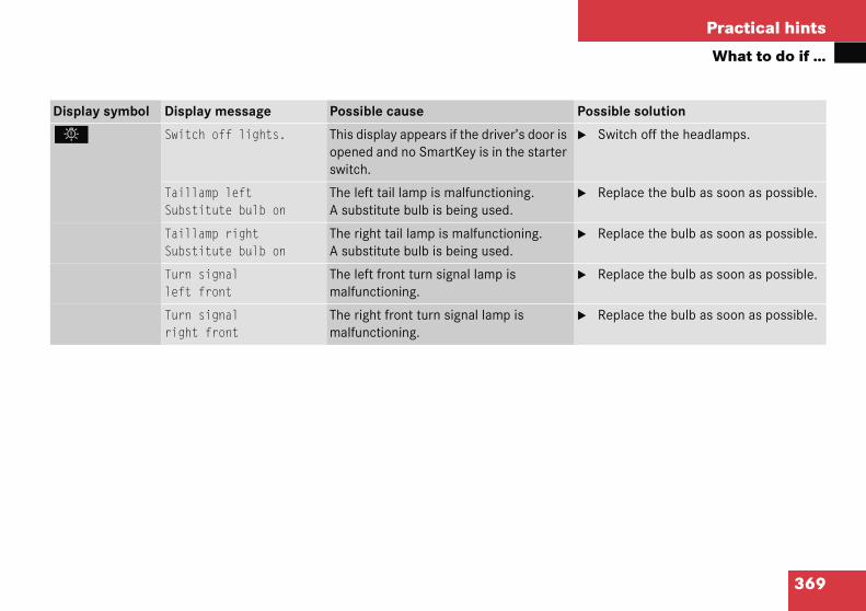
369
Practical hints
What to do if …
Displa Possible solution
. � Switch off the headlamps.
� Replace the bulb as soon as possible.
� Replace the bulb as soon as possible.
� Replace the bulb as soon as possible.
� Replace the bulb as soon as possible.
y symbol Display message Possible cause
Switch off lights. This display appears if the driver’s door is opened and no SmartKey is in the starter switch.
Taillamp leftSubstitute bulb on
The left tail lamp is malfunctioning. A substitute bulb is being used.
Taillamp rightSubstitute bulb on
The right tail lamp is malfunctioning. A substitute bulb is being used.
Turn signalleft front
The left front turn signal lamp is malfunctioning.
Turn signalright front
The right front turn signal lamp is malfunctioning.

370
Practical hints
What t
Display ossible solution
. Visit an authorized Mercedes-Benz Center as soon as possible.
Visit an authorized Mercedes-Benz Center as soon as possible.
Replace the bulb as soon as possible.
Replace the bulb as soon as possible.
o do if …
symbol Display message Possible cause P
Turn signalleft mirror
The left turn signal in the side mirror is malfunctioning. This message will only appear if all light emitting diodes have stopped working.
�
Turn signalright mirror
The right turn signal in the side mirror is malfunctioning. This message will only appear if all light emitting diodes have stopped working.
�
Turn signalleft rearSubstitute bulb on
The left rear turn signal lamp is malfunctioning. A substitute bulb is being used.
�
Turn signalright rearSubstitute bulb on
The right rear turn signal lamp is malfunctioning. A substitute bulb is being used.
�

371
Practical hints
What to do if …
Displa Possible solution
< g. � Visit an authorized Mercedes-Benz Center as soon as possible.
_ � Have the system checked by an authorized Mercedes-Benz Center.
Warn
If the too lofail. Mto tur
Do nosteeri
Do nocheckCente
y symbol Display message Possible cause
Belt systemDrive to workshop
The seat belt system is malfunctionin
Steering oilVisit workshop.
The steering gear oil level is too low. There is a danger of steering gear damage.
ing! G
level of steering gear oil in reservoir is w, the steering power assistance could uch greater effort will then be needed n the steering wheel.
t add steering oil without checking the ng system.
t drive the vehicle. Have the system ed at an authorized Mercedes-Benz r as soon as possible.

372
Practical hints
What t
Display ossible solution
K Close the panorama roof with power tilt/sliding panel (� page 242).
J Close the panorama roof with power tilt/sliding panel (� page 242).
L Have the Tele Aid system* checked by an authorized Mercedes-Benz Center.
t
Ê Close the trunk lid.
W Add washer fluid (� page 299).
o do if …
symbol Display message Possible cause P
Close slid./pop-upsunroof
You have opened the driver’s door with the SmartKey removed from the starter switch and the panorama roof with power tilt/sliding panel open.
�
Close slid./pop-upsunroof
You have opened the driver’s door with the SmartKey removed from the starter switch and the panorama roof with power tilt/sliding panel open.
�
Tele Aid malfunction.Drive to workshop
One or more main functions of the Tele Aid system* are malfunctioning.
�
Function unavailable. This display appears if button t or s on the multifunction steering wheel is pressed and the vehicle is not equipped with a telephone*.
Trunk open This message will appear whenever the trunk lid is open.
�
Washer fluidplease refill
The fluid level has dropped to about 1/3 of total reservoir capacity.
�
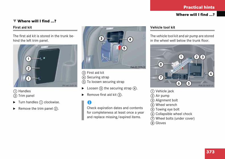
373
Practical hints
Where will I find ...?
�Fir
Thhin
12
�
�
Vehicle tool kit
The vehicle tool kit and air pump are stored in the wheel well below the trunk floor.
1 Vehicle jack2 Air pump3 Alignment bolt4 Wheel wrench5 Towing eye bolt6 Collapsible wheel chock7 Wheel bolts (under cover)8 Gloves
Wherst aid
e first ad the l
HandlTrim p
Turn h
Remov
e will I find ...?kit
id kit is stored in the trunk be-eft trim panel.
esanel
andles 1 clockwise.
e the trim panel 2.
3 First aid kit4 Securing strap5 To loosen securing strap
� Loosen 5 the securing strap 4.
� Remove first aid kit 3.
iCheck expiration dates and contents for completeness at least once a year and replace missing/expired items.

374
Practical hints
Where
Vehicle
Turn the crank handle clockwise until it engages (operational position).
efore storing the vehicle jack in its com-artment:
It should be fully collapsed.
The handle must be folded in (storage position).
Warni
The jacup the vbuilt intavoid pthe vehget benby the jthe arefirmly sbefore
Do not vehiclealways peciallyon levefully seways lopacity jvehicle
will I find ...?
jack
Storage position
� Remove the vehicle jack from the spare wheel well under the trunk floor.
� Push the crank handle up.
�
Bp
�
�
ng! G
k is designed exclusively for jacking ehicle at the jack take-up brackets o both sides of the vehicle. To help ersonal injury, use the jack only to lift icle during a wheel change. Never eath the vehicle while it is supported ack. Keep hands and feet away from a under the lifted vehicle. Always et parking brake and block wheels raising vehicle with jack.
disengage parking brake while the is raised. Be certain that the jack is vertical (plumb line) when in use, es- on hills. Always try to use the jack l surface. Make sure the jack arm is ated in the jack take-up bracket. Al-wer the vehicle onto sufficient ca-ack stands before working under the .
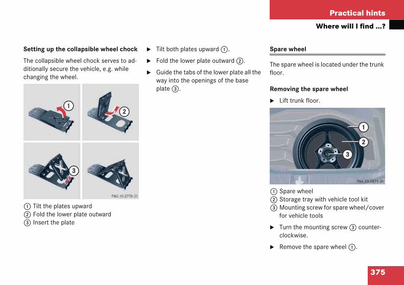
375
Practical hints
Where will I find ...?
Settin
The coditionachangi
1 Tilt2 Fol3 Ins
Spare wheel
The spare wheel is located under the trunk floor.
Removing the spare wheel
� Lift trunk floor.
1 Spare wheel2 Storage tray with vehicle tool kit3 Mounting screw for spare wheel/cover
for vehicle tools
� Turn the mounting screw 3 counter-clockwise.
� Remove the spare wheel 1.
g up the collapsible wheel chock
llapsible wheel chock serves to ad-lly secure the vehicle, e.g. while ng the wheel.
the plates upwardd the lower plate outwardert the plate
� Tilt both plates upward 1.
� Fold the lower plate outward 2.
� Guide the tabs of the lower plate all the way into the openings of the base plate 3.
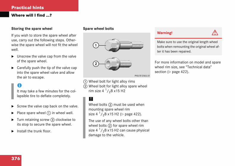
376
Practical hints
Where
Storing
If you wuse, carwise thewell.
� Unscof th
� Careinto the a
� Scre
� Place
� Turnits st
� Insta
or more information on model and spare heel rim size, see “Technical data” ection (� page 422).
iIt malapsi
Warning! G
Make sure to use the original length wheel bolts when remounting the original wheel af-ter it has been repaired.
will I find ...?
the spare wheel
ish to store the spare wheel after ry out the following steps. Other- spare wheel will not fit the wheel
rew the valve cap from the valve e spare wheel.
fully push the tip of the valve cap the spare wheel valve and allow ir to escape.
w the valve cap back on the valve.
spare wheel 1 in wheel well.
retaining screw 3 clockwise to op to secure the spare wheel.
ll the trunk floor.
Spare wheel bolts
1 Wheel bolt for light alloy rims2 Wheel bolt for light alloy spare wheel
rim size 4 1/2B x15 H2
Fws
y take a few minutes for the col-ble tire to deflate completely.
!Wheel bolts 2 must be used when mounting spare wheel rim size 4 1/2B x15 H2 (� page 422).
The use of any wheel bolts other than wheel bolts 2 for spare wheel rim size 4 1/2B x15 H2 can cause physical damage to the vehicle.
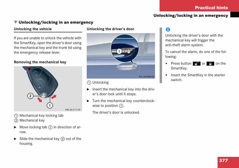
377
Practical hints
locking/locking in an emergency
�Un
If ythethethe
Re
12
�
�
iUnlocking the driver’s door with the mechanical key will trigger the anti-theft alarm system.
To cancel the alarm, do one of the fol-lowing:
� Press button Œ or ‹ on the SmartKey.
� Insert the SmartKey in the starter switch.
Unloclockin
ou are Smart mecha emerg
movin
MechaMecha
Move row.
Slide thousin
Un
king/locking in an emergencyg the vehicle
unable to unlock the vehicle with Key, open the driver’s door using nical key and the trunk lid using ency release lever.
g the mechanical key
nical key locking tabnical key
locking tab 1 in direction of ar-
he mechanical key 2 out of the g.
Unlocking the driver’s door
1 Unlocking
� Insert the mechanical key into the driv-er’s door lock until it stops.
� Turn the mechanical key counterclock-wise to position 1.
The driver’s door is unlocked.

378
Practical hints
Unlock
Unlocki
A minim(2.16 m
The emeinside o
1 Cove2 Eme3 Rear
iIf the vehicle has previously been locked from the outside with the SmartKey, opening the trunk from the inside using the emergency release le-ver will trigger the anti-theft alarm sys-tem*.
To cancel the alarm, do one of the fol-lowing:
� Press button Œ or ‹ on the SmartKey.
� Insert the SmartKey in the starter switch.
ing/locking in an emergency
ng and opening the trunk lid
um height clearance of 7.1 ft. ) is required to open the trunk lid.
rgency release is located on the f the trunk lid.
rrgency release lever bench seat backrest
� Fold backrest 3 forward (� page 251).
� Remove cover 1 from the trim on the trunk lid.
� Push release lever 2 all the way to the right.
The trunk lid unlocks.
� Lift the trunk lid.
!Always make sure there is sufficient overhead clearance.

379
Practical hints
locking/locking in an emergency
Lockin
If you athe Sm
� Clolid.
� Precen
� Cheon dow
� If n
Excsho
Fuel filler flap
In case the central locking system does not release the fuel filler flap, you can open it manually.
Warning! G
If you operate the emergency release but-ton, be careful of the sharp edges so that you do not injure yourself.
Un
g the vehicle
re unable to lock the vehicle with artKey, do the following:
se the passenger door and the trunk
ss the central locking switch in the ter console (� page 98).
ck to see whether the locking knob the passenger door have moved n.
ecessary push them down manually.
ept for the driver's door, the vehicle uld now be locked.
1 Locking
� Insert the mechanical key into the driver’s door lock until it stops.
� Turn the mechanical key clockwise to position 1.
The driver’s door is locked.

380
Practical hints
Unlock
The releside of tthe side
1 Side2 Rele
� Open
� Remrightmen
� Turnas w
The f
� Open
� Press tool 1 forward in the direc-tion of the arrow.
� Move gear selector lever from position P.
Remove tool 1 from the opening.
iThe gear selector lever is locked again when moving it to position P.
ing/locking in an emergency
ase button is on the right-hand he luggage compartment behind trim.
trimase button
the trunk lid.
ove the side trim 1 from the -hand side of the luggage compart-t.
release button 2 clockwise as far ill go.
uel filler flap is released.
the fuel filler flap from outside.
Manually unlocking the gear selector lever
In the case of power failure the gear selec-tor lever can be manually unlocked, e.g. to tow the vehicle.
� Slide out the swiveling cup holder (� page 256).
1 Tool
� Insert a tool 1 (e.g. flat blade screw driver) into the opening.
� Perform the following two steps simultaneously:
�

381
Practical hints
pening/closing in an emergency
�Papa
Yomaoc
Thhin
�
�
� Take the crank 3 out of the Operator’s Manual pouch.
� Insert crank 3 through hole.
� Turn crank 3 clockwise to:
� slide roof closed
� raise roof at the rear
� Turn crank 3 counterclockwise to:
� slide roof open
� lower roof at the rear
The tilt/sliding panel must be resynchro-nized after being operated manually (� page 246).
Opennoramnel*
u can onually
cur.
e tilt/sd the le
Remov
Pry offdriver.
O
ing/closing in an emergencya roof with power tilt/sliding
pen or close the tilt/sliding panel should an electrical malfunction
liding panel drive is located be-ns of the interior overhead light.
e SmartKey from starter switch.
lens 1 using a flat blade screw-
� Slide both locking tabs 2 in direction of arrow.
� Lower the rear of cover and remove.
� Remove the cover.
iDo not disconnect electrical connec-tors.

Practical hints
c
ad oee
i
th
ttdi
iWhen inserting the batteries, make sure they are clean and free of lint.
iWhen changing batteries, always replace both batteries.
The required replacement batteries are available at any Mercedes-Benz Center.
382
Repla
If the bchargelockedhave thrized M
Warn
Keep
If a baimme
ing SmartKey batteries
tteries in the SmartKey are dis-, the vehicle can no longer be r unlocked. It is recommended to batteries replaced at an autho-rcedes-Benz Center.
Batteries contain materials that can harm the environment if disposed of improperly. Recycling of batteries is the preferred method of disposal. Many states require sellers of batteries to accept old batteries for recycling.
ng! G
e batteries out of reach of children.
ery is swallowed, seek medical help ately.
383
Practical hints
Replacing SmartKey batteries
Smart
ReplacCR 202
� Rem(�
1 Me2 Bat
� Using a lint-free cloth, insert new batteries 3 under contact spring 4 with the plus (+) side facing up.
� Return battery compartment into the housing until it locks in place.
� Slide mechanical key 1 back into the SmartKey.
� Check the operation of the SmartKey.
Key
ement batteries: Lithium, type 5 or equivalent.
ove mechanical key 1 page 377).
chanical keytery compartment
� Insert mechanical key 1 in side opening and push grey slide.
Battery compartment 2 is unlatched.
� Pull the battery compartment 2 out of the key housing in direction of arrow.
� Remove the batteries.
3 Battery4 Contact spring

Practical hints
c
hr ses
t anstse
ulbs
384
Repla
Safe veexteriofore essemblitimes.
Correcimportreadjubulb haMercedadjustm
ing bulbs
icle operation depends on proper lighting and signaling. It is there-ential that all bulbs and lamp as- are in good working order at all
headlamp adjustment is extremely t. Have headlamps checked and
ed at regular intervals and when a been replaced. See an authorized s-Benz Center for headlamp
ent.
BiIf the headlamps or front fog lamps are fogged up on the inside as a result of high humidity, driving the vehicle a dis-tance with the lights on should clear up the fogging.
iSubstitute bulbs will be brought into use when lamps malfunction. Observe the messages in the multifunction dis-play (� page 366).
385
Practical hints
Replacing bulbs
Front Rear lamps
La
1 Adlam
2 HasigBi-Tu
3 HaLoBi-Lo
1 Vehicand hnot reautho
Lamp Type
7 High mounted brake lamp
LED
8 License plate lamps C 5 W
9 Brake lamp P 21 W
Turn signal lamp PY21W
Tail, parking, standing and side marker lamp
P21/5W
Rear fog lamp (only driver’s side)
P21/4W
lamps
mp Type
ditional turn signal ps
LED
logen headlamp: Turn nal lamp Xenon* headlamp: rn signal lamp
1156 A
2357 A
logen headlamps:w beam1
Xenon* headlamp:w and high beam
les with Bi-Xenon* headlamps: Low beamigh beam use the same D2S-35W lamp. Doplace the Xenon bulbs yourself. See an
rized Mercedes-Benz Center.
H7 (55 W)
D2S-35 W
Lamp Type
4 Halogen headlamps:High beam/high beam flasherBi-Xenon* headlamps:High beam flasher
H7 (55 W)
H7 (55 W)
Parking and standing lamps
W 5 W
5 Fog lamp
Front fog lamp with cornering fog lamp
HB4 (51 W)
H7 (55 W)
6 Side marker lamp W 5 W

386
Practical hints
Replac
eplacing bulbs for front lamps
efore you start to replace a bulb for a ont lamp, do the following first:
Turn the exterior lamp switch to position M (� page 110).
Open the hood (� page 291) (except for side marker lamps).
alogen headlamps
eft headlamp, mirror-image of right eadlamp
Housing cover for low beam headlamp Housing cover for high beam head-lamp, parking and standing lamp
Warni
Bulbs alow thea bulb.
Keep bu
HalogenA bulb c
� tou
� dro
� scra
Wear ey
Becausdangerolamp anthat youtechnic
ing bulbs
Notes on bulb replacement
� Use only 12-volt bulbs of the same type and with the specified watt rating.
� Switch lights off before replacing a bulb to prevent short circuits.
� Always use a clean lint-free cloth when handling bulbs.
� Your hands should be dry and free of oil and grease.
� If the newly installed bulb does not come on, visit an authorized Mercedes-Benz Center.
Have the LEDs and bulbs for the following lamps replaced by an authorized Mercedes-Benz Center.
� Additional turn signals in the exterior rear view mirrors
� High mounted brake lamp
� Xenon* lamps
� Front fog lamps
R
Bfr
�
�
H
Lh
12
ng! G
nd bulb sockets can be very hot. Al- lamp to cool down before changing
lbs out of reach of children.
lamps contain pressurized gas. an explode if you
ch or move it when hot
p the bulb
tch the bulb
e and hand protection.
e of high voltage in Xenon lamps, it is us to replace the bulb or repair the d its components. We recommend have such work done by a qualified
ian.

387
Practical hints
Replacing bulbs
3 Bul4 Bul5 Bul6 Bul
lam
High beam bulb
� Turn housing cover 2 counterclock-wise and remove it.
� Turn bulb holder 5 with the bulb coun-terclockwise and remove it.
� Pull the bulb at its socket out of bulb holder 5.
� Insert the new bulb so that its socket locates in the recess of bulb holder 5 and is level to it.
� Reinsert bulb holder 5 with the bulb in the lamp and turn clockwise.
� Align housing cover 2 and turn it clockwise.
b socket for turn signal lamp bulbb holder of low beam bulbb holder of high beam bulbb socket for parking and standing p bulb
Low beam bulb
� Turn housing cover 1 counterclock-wise and remove it.
� Turn bulb holder 4 with the bulb coun-terclockwise and remove it.
� Pull the bulb at its socket out of bulb holder 4.
� Insert the new bulb so that its socket locates in the recess of bulb holder 4 and is level to it.
� Reinsert bulb holder 4 with the bulb in the lamp and turn clockwise.
� Align housing cover 1 and turn it clockwise.

388
Practical hints
Replac
Front tu
� Turnand
� Prescounsock
� Pressockenga
� Placelamp
i-Xenon* headlamps
Warning! G
Do not remove the cover 1 for the Bi-Xenon headlamp. Because of high voltage in Bi-Xenon lamps, it is dangerous to replace the bulb or repair the lamp and its compo-nents. We recommend that you have such work done by a qualified technician.
ing bulbs
rn signal lamp bulb
bulb socket 3 counterclockwise remove it.
s gently onto the bulb and turn terclockwise out of bulb et 3.
s the new bulb gently into bulb et 3 and turn clockwise until it ges.
bulb socket 3 back into the and turn it clockwise.
Parking and standing lamp bulb
� Turn housing cover 2 counterclock-wise and remove it.
� Pull out bulb socket 6 with the bulb.
� Pull the bulb out of bulb socket 6.
� Press the new bulb into bulb socket 6.
� Press bulb socket 6 back into the lamp.
� Align housing cover 2 and turn it clockwise.
B

389
Practical hints
Replacing bulbs
Left heheadla
1 Ho2 Ho
par
� Reinsert bulb holder 4 with the bulb in the lamp and turn clockwise.
� Align housing cover 2 and turn it clockwise.
Front turn signal lamp bulb
� Turn bulb socket 3 with the bulb counterclockwise and remove it.
� Press gently onto the bulb and turn counterclockwise out of bulb socket 3.
� Press the new bulb gently into bulb socket 3 and turn clockwise until it engages.
� Place bulb socket 3 back into the lamp and turn it clockwise.
adlamp, mirror-image of right mp
using cover for Bi-Xenon headlampusing cover for high beam flasher, king and standing lamp
3 Bulb socket for turn signal lamp4 Bulb holder for high beam flasher5 Bulb socket for parking and standing
lamp bulb
High beam bulb for high beam flasher
� Turn housing cover 2 counterclock-wise and remove it.
� Turn bulb holder 4 with the bulb coun-terclockwise and remove it.
� Pull the bulb at its socket out of bulb holder 4.
� Insert the new bulb so that its socket locates in the recess of bulb holder 4 and is level to it.

390
Practical hints
Replac
Parking
� Turnwise
� Pull
� Pull
� Pres
� Preslamp
� Alignclock
eplacing bulbs for rear lamps
efore you start to replace a bulb for a rear mp, do the following first:
Turn the exterior lamp switch to position M (� page 110).
ail lamp unit
Trim panelLatch
Open the trunk lid.
Turn latches 1 on respective trim panel 2 clockwise.
Fold trim panel 2 to the side.
ing bulbs
and standing lamp bulb
housing cover 2 counterclock- and remove it.
out bulb socket 5 with the bulb.
the bulb out of bulb socket 5.
s the new bulb into bulb socket 5.
s bulb socket 5 back into the .
housing cover 2 and turn it wise.
Side marker lamp bulb
� Carefully slide the lamp towards the rear in direction of arrows.
� Remove the front end first.
� Turn the bulb socket with the bulb counterclockwise and remove it.
� Pull the bulb out of the bulb socket.
� Insert the new bulb into the bulb sock-et.
� Place the bulb socket back into the lamp and turn it clockwise.
� To reinstall the lamp, set the rear end in the bumper and let the front end en-gage.
R
Bla
�
T
12
�
�
�
391
Practical hints
Replacing bulbs
3 Tab4 Bul
� Pre
� Rem
� Preandbul
� Presocgag
Side marker lamp
The bulb socket for the side marker lamp bulb is located between the bulb carrier and the vehicle’s body.
� Open the trunk lid.
� Turn latches 1 on respective trim panel 2 clockwise.
� Fold trim panel 2 to the side.
� Pull bulb socket 4 with the bulb out of its holder.
� Pull the bulb out of bulb socket 4.
� Press the new bulb into bulb socket 4.
� Press bulb socket 4 back into its holder.
� Reinstall trim panel 2.
� Turn latches 1 counterclockwise.
b socket for side marker lamp bulb
ss tabs 3 together.
ove the bulb carrier.
ss gently onto the respective bulb turn counterclockwise out of its
b socket.
ss the new bulb gently into its bulb ket and turn clockwise until it en-es.
5 Brake lamp bulb6 Backup lamp bulb7 Turn signal lamp bulb8 Rear fog lamp bulb (only driver’s side),
tail, parking and standing lamp
� Reinstall the bulb carrier.
Let tabs 3 engage.
� Reinstall trim panel 2.
� Turn latches 1 counterclockwise.
392
Practical hints
Replac
License
1 Scre
� Loostive s
� Rem
� Repl
� Rein
� Retig
ing bulbs
plate lamp
w
en both screws 1 of the respec-ide.
ove the license plate lamp.
ace the bulb.
stall the license plate lamp.
hten screws 1.

393
Practical hints
Replacing wiper blades
�
Re
�
�
12
W
Fsbt
!Never open the hood when the wiper arm is folded forward.
Hold onto the wiper when folding the wiper arm back. If released, the force of the impact from the tensioning spring could crack the windshield.
Do not allow the wiper arms to contact the windshield glass without a wiper blade inserted.
Make certain that the wiper blades are properly installed. Improperly installed wiper blades may cause windshield damage.
For your convenience, we recommend that you have this work carried out by an authorized Mercedes-Benz Center.
Repla
movin
Remov
Fold w
UnlockLock
arning
or safettarter swlade, oturn on a
cing wiper blades
g
e SmartKey from starter switch.
iper arm forward.
� Pull the tab in the direction of arrow 1 and remove windshield wiper.
Installing
� Slide the wiper blade into the cutout on the wiper arm (see arrows).
� Slide the tab back in the direction of arrow 2 until it audibly engages.
� Fold the wiper arm back to rest on the windshield.
! G
y reasons, remove SmartKey from itch before replacing a wiper
herwise the motor could suddenly nd cause injury.

Practical hints
ir
ounting the spare wheel
reparing the vehicle
repare the vehicle as described page 394).
Take the wheel wrench and the jack out of wheel well below the trunk floor (� page 373).
Take the spare wheel out of the trunk (� page 375).
i
im f, tete
a droe
tone
opa
394
Flat t
Warn
The dferentresultchangmouningly.
The spWhensure pvehicl
Drive as sooreplac
Neverone s
e
Preparing the vehicle
� Park the vehicle as far as possible from moving traffic on a hard surface.
� Turn on the hazard warning flashers.
� Turn the steering wheel so that the front wheels are in a straight ahead position.
� Move the gear selector lever to P (manual transmission to first or reverse gear).
� Turn off the engine (� page 58).
� Remove the SmartKey from the starter switch.
� Have any passenger exit the vehicle at a safe distance from the roadway.
M
P
P(�
�
�
ng! G
ensions of the spare wheel are dif-rom those of the road wheels. As a he vehicle handling characteristics when driving with a spare wheel d. Adapt your driving style accord-
re wheel is for temporary use only. riving with spare wheel mounted, en-per tire pressure and do not exceed
speed of 50 mph (80 km/h).
the nearest Mercedes-Benz Center as possible to have the spare wheel d with a regular road wheel.
perate the vehicle with more than re wheel mounted.
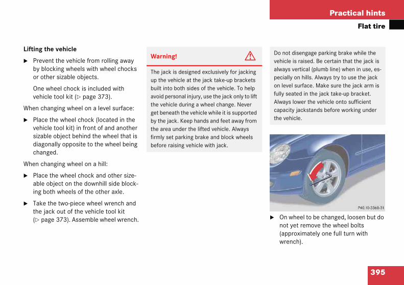
395
Practical hints
Flat tire
Lifting
� Preby or o
Onveh
When c
� Plavehsizadiacha
When c
� Plaabling
� Takthe(� � On wheel to be changed, loosen but do
not yet remove the wheel bolts (approximately one full turn with wrench).
Do not disengage parking brake while the vehicle is raised. Be certain that the jack is always vertical (plumb line) when in use, es-pecially on hills. Always try to use the jack on level surface. Make sure the jack arm is fully seated in the jack take-up bracket. Always lower the vehicle onto sufficient capacity jackstands before working under the vehicle.
the vehicle
vent the vehicle from rolling away blocking wheels with wheel chocks ther sizable objects.
e wheel chock is included with icle tool kit (� page 373).
hanging wheel on a level surface:
ce the wheel chock (located in the icle tool kit) in front of and another ble object behind the wheel that is
gonally opposite to the wheel being nged.
hanging wheel on a hill:
ce the wheel chock and other size-e object on the downhill side block- both wheels of the other axle.
e the two-piece wheel wrench and jack out of the vehicle tool kit page 373). Assemble wheel wrench.
Warning! G
The jack is designed exclusively for jacking up the vehicle at the jack take-up brackets built into both sides of the vehicle. To help avoid personal injury, use the jack only to lift the vehicle during a wheel change. Never get beneath the vehicle while it is supported by the jack. Keep hands and feet away from the area under the lifted vehicle. Always firmly set parking brake and block wheels before raising vehicle with jack.

396
Practical hints
Flat tir
The jackdirectly and in fr
1 Jack2 Cran3 Take
� Place
� Positbrac(plumeveninclin
emoving the wheel
Alignment bolt
Unscrew upper-most wheel bolt and remove.
Replace this wheel bolt with the align-ment bolt 1 supplied in the tool kit.
Remove the remaining bolts.
Remove the wheel.
!Do not place wheel bolts in sand or dirt. This could result in damage to the bolt and wheel hub threads.
e
take-up brackets are located behind the front wheel housings ont of the rear wheel housings.
k-up bracket
jack on firm ground.
ion jack 1 under the take-up ket 3 so that it is always vertical b-line) as seen from the side,
if the vehicle is parked on an e.
� Jack up the vehicle until the wheel is a maximum of 1.2 in (3 cm) from the ground. Never start engine while vehi-cle is raised.
R
1
�
�
�
�
Warning! G
The jack is intended only for lifting the vehicle briefly for wheel changes. It is not suited for performing maintenance work un-der the vehicle.
� Never start the engine when the vehicle is raised.
� Never lie down under the raised vehicle.

397
Practical hints
Flat tire
Mount
1 Wh2 Wh
rim
� Clewh
� Guide the spare wheel onto the align-ment bolt and push it on.
� Insert wheel bolts and tighten them slightly.
� Inflate the spare tire using the electric air pump (� page 398).
!Whmosize
Thewhsizedam
Warning! G
Inflate spare wheel with collapsible tire only after the wheel is properly mounted.
Inflate the spare wheel tire using the electric air pump before lowering the vehicle. ��
ing the spare wheel
eel bolt for light alloy rimseel bolt for light alloy spare wheel size 4 1/2B x15 H2
an contact surfaces of wheel and eel hub.
eel bolts 2 must be used when unting spare wheel rim
4 1/2B x 15 H2 (� page 422).
use of any wheel bolts other than eel bolts 2 for spare wheel rim
4 1/2B x15 H2 can cause physical age to the vehicle.
!To avoid paint damage, place wheel flat against hub and hold it there while installing first wheel bolt.
Warning! G
Always replace wheel bolts that are dam-aged or rusted.
Never apply oil or grease to wheel bolts.
Damaged wheel hub threads should be re-paired immediately. Do not continue to drive under these circumstances! Contact an authorized Mercedes-Benz Center or call Roadside Assistance.
Incorrect wheel bolts or improperly tight-ened wheel bolts can cause the wheel to come off. This could cause an accident. Make sure to use the correct mounting bolts.

398
Practical hints
Flat tir
� Unscwhee
Take the electric air pump out of the trunk.
FlapOn/off switchElectrical plugAir hose with pressure gauge and vent screwUnion nut
Warni
Use onlMercedbolts m
Do not hicle is fall off t
��
e
rew the alignment bolt, install last l bolt and tighten slightly.
Inflating the spare tire �
1234
5
ng! G
y genuine equipment es-Benz wheel bolts. Other wheel ay come loose.
tighten the wheel bolts when the ve-raised. Otherwise the vehicle could he jack.
Warning! G
Inflate spare wheel with collapsible tire only after the wheel is properly mounted.
Inflate the spare wheel tire using the electric air pump before lowering the vehicle.
Warning! G
Observe instructions on air pump label.
!Do not lower the vehicle before inflat-ing the collapsible tire. Otherwise the rim may be damaged.

399
Practical hints
Flat tire
� Op
� Pulwit
� Rem
� Scr
� Inscig
� Turto p
� Pre
Theswi
� Infl36
Thispanuttionburme
� Detach the electric air pump.
� Store the electrical plug and the air hose behind the flap and place the air pump back in the trunk.
Warning! G
Follow recommended inflation pressures.
Do not overinflate tires. Overinflated tires can result in sudden deflation (blowout) be-cause they are more likely to become punc-tured or damaged by road debris, potholes, etc.
Do not underinflate tires. Underinflated tires wear unevenly, adversely affect handling and fuel economy, and are more likely to fail from being overheated.
en flap 1 on electric air pump.
l out electrical plug 3 and air hose h pressure gauge 4.
ove the valve cap from valve.
ew air hose 4 onto the tire valve.
ert electrical plug 3 into vehicle arette lighter socket.
n the SmartKey in the starter switch osition 1.
ss I on electric air pump switch 2.
electric air pump should now tch on and inflate the spare tire.
ate the spare tire to approximately psi (2.5 bar).
s takes about five minutes for the re tire. Air hose 4 and union 5 can become hot during infla-. Exercise proper caution to avoid ning yourself when using the equip-nt.
� Press 0 on electric air pump switch 2.
� Turn the SmartKey in the starter switch to position 0.
� If the tire pressure is above 36 psi (2.5 bar), release excess tire pressure using the vent screw.
!Do not operate the electric air pump longer than six minutes without interruption. Otherwise it may over-heat.
You may operate the electric air pump again after it has cooled off.

400
Practical hints
Flat tir
Lowerin
� Loweterclly on
� Rem
efore storing the jack, it should be fully ollapsed, with handle folded in (storage osition) (� page 374).
Store the jack, the damaged wheel and the other vehicle tools in the wheel well below the trunk floor (� page 375).
Warni
Inflate safter th
Inflate tair pum
Warning! G
Have the tightening torque checked after changing a wheel. The wheels could come loose if they are not tightened to a torque of 80 lb-ft (110 Nm).
e
g the vehicle
r vehicle by turning crank coun-ockwise until vehicle is resting ful- its own weight.
ove the jack.
1 - 5 Wheel bolts
� Tighten the five wheel bolts evenly, fol-lowing the diagonal sequence illustrated (1 to 5), until all bolts are tight. Observe a tightening torque of 80 lb-ft (110 Nm).
Bcp
�
ng! G
pare wheel with collapsible tire only e wheel is properly mounted.
he spare wheel tire using the electric p before lowering the vehicle.

401
Practical hints
Battery
�Thpa
1
Re
�
�
Ins
�
�
!Never loosen or detach battery termi-nal clamps while the engine is running or the SmartKey is in the starter switch. Otherwise the alternator and other electronic components could be se-verely damaged.
Have the battery checked regularly by an authorized Mercedes-Benz Center.
Refer to Maintenance Booklet for main-tenance intervals or contact an autho-rized Mercedes-Benz Center for further information.
Warning! G
Do not place metal objects on the battery as this could result in a short circuit.
Use leak-proof battery only to avoid the risk of acid burns in the event of an accident. ��
Battee battertment
Clamp
moving
Releas
Remov
talling
Insert
Secure
ryry is located in the engine com-on the right hand side.
s
filter box
e clamps 1.
e filter box.
filter box
filter box properly.
it with clamps 1.
Warning! G
Failure to follow these instructions can re-sult in severe injury or death.
Observe all safety instructions and precau-tions when handling automotive batteries (� page 297).
Never lean over batteries while connecting, you might get injured.
Battery fluid contains sulfuric acid. Do not allow this fluid to come in contact with eyes, skin or clothing. In case it does, immediately flush affected area with water and seek medical help if necessary.
A battery will also produce hydrogen gas, which is flammable and explosive. Keep flames or sparks away from battery, avoid improper connection of jumper cables, smoking, etc.

402
Practical hints
Batter
1 Nega2 Posit
harging and reinstalling battery
Charge battery in accordance with the instructions of the battery charger manufacturer.
Reinstall the charged battery. Follow the previously described steps in re-verse order.
Warni
With a d
� youSm
� thelock
��
y
tive terminalive terminal cover
Disconnecting the battery
� Turn off the engine (� page 58).
� Turn off all electrical consumers.
� Remove SmartKey from starter switch.
� Open the hood (� page 291).
� Read and observe safety instructions and precautions (� page 297).
� Remove the filter box (� page 401).
� Disconnect battery negative lead from negative terminal 1.
� Remove cover 2 from the positive terminal.
� Disconnect the battery positive lead.
Removing the battery
� Remove the screw-nuts securing the battery.
� Remove the battery bracket.
� Take out the battery.
C
�
�
ng! G
isconnected battery
will no longer be able to turn the artKey in the starter switch
gear selector lever will remain ed in position P

403
Practical hints
Battery
Batteries contain materials that can harm the environment if disposed of improperly. Large 12-volt storage batteries contain lead. Recycling of batteries is the preferred method of disposal. Many states require sellers of batteries to accept old batteries for recycling.
Warn
Neverthe vechargbeinging anpaint
An acadapttestedavailatery inthorizinformin accacces
iThe following procedures must be car-ried out following any interruption of battery power (e.g. due to reconnec-tion):
� Set the clock (� page 139) (vehi-cles with COMAND*: see COMAND operator’s manual).
� Resynchronize side windows (� page 240).
� Resynchronize panorama roof with power tilt/sliding panel* (� page 246).
Reconnecting the battery
� Turn off all electrical consumers.
� Remove SmartKey from the starter switch.
� Connect the positive lead and fasten its cover 2 (� page 402).
� Connect the negative lead.
� Reinstall the filter box (� page 401).
ing! G
charge a battery while still installed in hicle unless the accessory battery e unit approved by Mercedes-Benz is used. Gases may escape during charg-d cause explosions that may result in damage, corrosion or personal injury.
cessory battery charge unit specially ed for Mercedes-Benz vehicles and and approved by Mercedes-Benz is ble, permitting the charging of the bat- its installed position. Contact an au-
ed Mercedes-Benz Center for ation and availability. Charge battery ordance with the instructions for the sory battery charger.
!NEVER invert the terminal connections!
!The battery, its filler caps and the vent tube must always be securely installed when the vehicle is in operation.
Practical hints
s
i
e gea o
lp
ythr afa
e iss pin
ps
.
al
!Jump starting may only be performed on the battery installed in the engine compartment.
Avoid repeated and lengthy starting attempts.
Do not attempt to start the engine using a battery quick charge unit.
If engine does not run after several unsuccessful starting attempts, have it checked at the nearest authorized Mercedes-Benz Center.
Excessive unburned fuel generated by repeated failed starting attempts may damage the catalytic converter and may present a fire risk.
Make sure the jumper cables do not have loose or missing insulation.
Make sure the cable clamps do not touch any other metal part while the other end is still attached to a battery.
404
Jump
Warn
Failurdamacan leinjury
Neveror jum
Batterallow skin oflush medic
A battwhichflameimprosmok
Attemcan reinjury
Read
tarting
If the battery is discharged, the engine can be started with jumper cables and the bat-tery of another vehicle. Observe the follow-ing:
� Jump starting should only be performed when the engine and catalytic convert-er are cold.
� Do not start the engine if the battery is frozen. Let the battery thaw out first.
� Only jump start from batteries with the same voltage rating (12 V). Jump start-ing with a more powerful battery could damage the vehicle’s electrical system, which will not be covered by the Mercedes-Benz Limited Warranty.
� Use only jumper cables with sufficient cross-section and insulated terminal clamps.
� Always make sure the jumper cables are not on or near pulleys, fans or other parts that move when an engine is started or running.
ng! G
to follow these directions will cause to the electronic components, and
d to a battery explosion and severe r death.
ean over batteries while connecting starting, you might get injured.
fluid contains sulfuric acid. Do not is fluid to come in contact with eyes, clothing. In case it does, immediately fected area with water, and seek l help if necessary.
ry will also produce hydrogen gas, flammable and very explosive. Keep
or sparks away from battery, avoid er connection of jumper cables, g, etc.
ting to jump start a frozen battery ult in it exploding, causing personal
l instructions before proceeding.
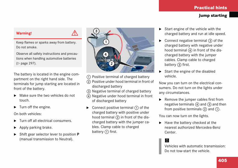
405
Practical hints
Jump starting
The bapartmeterminfront o
� Matou
� Tur
On bot
� Tur
� App
� Shi(ma
� Start engine of the vehicle with the charged battery and run at idle speed.
� Connect negative terminal 3 of the charged battery with negative under hood terminal 4 in front of the dis-charged battery with the jumper cables. Clamp cable to charged battery 3 first.
� Start the engine of the disabled vehicle.
Now you can turn on the electrical con-sumers. Do not turn on the lights under any circumstances.
� Remove the jumper cables first from negative terminals 4 and 3 and then from positive terminals 2 and 1.
You can now turn on the lights.
� Have the battery checked at the nearest authorized Mercedes-Benz Center.
Warn
Keep Do no
Obsertions (� pa
!Vehicles with automatic transmission:Do not tow-start the vehicle.
ttery is located in the engine com-nt on the right hand side. The
als for jump starting are located in f the battery.
ke sure the two vehicles do not ch.
n off the engine.
h vehicles:
n off all electrical consumers.
ly parking brake.
ft gear selector lever to position P nual transmission to Neutral).
1 Positive terminal of charged battery2 Positive under hood terminal in front of
discharged battery3 Negative terminal of charged battery4 Negative under hood terminal in front
of discharged battery
� Connect positive terminal 1 of the charged battery with positive under hood terminal 2 in front of the dis-charged battery with the jumper ca-bles. Clamp cable to charged battery 1 first.
ing! G
flames or sparks away from battery. t smoke.
ve all safety instructions and precau-when handling automotive batteries ge 297).

Practical hints
g
detr ullyto
nne
ni
p
prnop
itpati
!If the vehicle is towed with the front axle raised, the engine must be shut off (SmartKey in starter switch position 0 or 1). Otherwise, the ESP will immedi-ately be engaged and will apply the rear wheel brakes.
When towing the vehicle with all wheels on the ground, the gear selector lever must be in position N (manual trans-mission: gears disengaged) and the SmartKey must be in starter switch position 2.
When towing the vehicle with all wheels on the ground or the front axle raised, the vehicle may be towed only for dis-tances up to 30 miles (50 km) and at a speed not to exceed 30 mph (50 km/h).
406
Towin
Mercecle be groundlift/doerable
!Usemetur
DoTowbumsup
To do sus
Sw(�ma
the vehicle
s-Benz recommends that the vehi-ansported with all wheels off the sing flatbed or appropriate wheel equipment. This method is pref- other types of towing.
When circumstances do not permit the recommended towing methods, the vehi-cle may be towed with all wheels on the ground or front wheels raised only so far as necessary to have the vehicle moved to a safe location where the recommended towing methods can be employed.
flatbed or wheel lift/dolly equip-t with SmartKey in starter switch d to position 0.
ot tow with sling-type equipment. ng with sling-type equipment over py roads will damage radiator and orts.
event damage during transport, t tie down vehicle by its chassis or
ension parts.
ch off the tow-away alarm ge 87) and deactivate the auto-
c central locking (� page 148).
!Vehicles with automatic transmission:Do not tow-start the vehicle.

407
Practical hints
Towing the vehicle
!To damwe confor nea
iTo signal turns while being towed with the hazard warning flasher in use, turn SmartKey in starter switch to position 2 and activate the combina-tion switch for the left or right turn sig-nal in the usual manner – only the selected turn signal will operate.
Upon canceling the turn signal, the hazard warning flasher will operate again.
be certain to avoid a possibility of age to the transmission, however,
recommend the drive shaft be dis-nected at the rear axle drive flange any towing beyond a short tow to a rby garage.
Warning! G
If circumstances require towing the vehicle with all wheels on the ground, always tow with a tow bar if:
� the engine will not run
� there is a malfunction in the power sup-ply or in the vehicle’s electrical system
as that will be necessary to adequately con-trol the towed vehicle.
Prior to towing the vehicle with all wheels on the ground, make sure the SmartKey is in starter switch position 2.
If the SmartKey is left in starter switch position 0 for an extended period of time, it can no longer be turned in the switch. In this case, the steering is locked. To unlock, re-move SmartKey from starter switch and re-insert.
408
Practical hints
Towing
Warni
With thpower asystemin mindeffort ishicle. A
iIf the battery is disconnected or dis-charged
� the SmartKey will not turn in the starter switch. For more informa-tion, see “Battery” (� page 401) and “Jump starting” (� page 404).
� the gear selector lever will remain locked in position P. For informa-tion on manually unlocking trans-mission gear selector lever, see (� page 380).
the vehicle
ng! G
e engine not running, there is no ssistance for the brake and steering
s. In this case, it is important to keep that a considerably higher degree of necessary to brake and steer the ve-dapt your driving accordingly.
!When towing the vehicle with all wheels on the ground, please note the follow-ing:
With the automatic central locking acti-vated and the SmartKey in starter switch position 2, the vehicle doors lock if the left front wheel as well as the right rear wheel are turning at vehicle speeds of approximately 9 mph (15 km/h) or more.
Switch off the tow-away alarm (� page 87).
To prevent the vehicle doors from lock-ing, deactivate the automatic central locking (� page 148).
Towing of the vehicle should only be done using the properly installed tow-ing eye bolt. Never attach tow cable, tow rope or tow rod to vehicle chassis, frame or suspension parts.

409
Practical hints
Towing the vehicle
Install
1 Cov
To remove cover:
� Press mark on cover 1 or 2 in direc-tion of arrow.
� Lift cover off to reveal threaded hole for towing eye bolt.
The towing eye bolt is supplied with the tool kit (located in the wheel well below the trunk floor).
� Screw towing eye bolt in to its stop and tighten with lug wrench.
To reinstall cover:
� Fit cover 1 or 2 and snap into place.
ing towing eye bolt
er on right side of front bumper.
2 Cover on right side of rear bumper.
Practical hints
cemt n
lo
e
r
e
ids for changing fuses
use chart
he fuse chart is found in the main fuse ox in the passenger compartment
page 411). The amperages of the fuses re also given there.
pare fuses
pare fuses are found in the vehicle tool kit the spare wheel well (� page 373).
use extractor
he fuse extractor is found in the fuse box over in the trunk (� page 412).
i
shes a
410
Fuses
The elestop ththat is prevenelectro
The folchange
� Fus
� Spa
� Fus
Warn
Only uwith tin queresult
trical fuses in your vehicle serve to supply of electricity to a device alfunctioning. This helps to damage to the other vehicle ics.
wing aids are available to help you fuses.
chart
e fuses
extractor
The electrical fuses are located in different fuse boxes.
� Main fuse box in passenger compart-ment (� page 411)
� Fuse box in engine compartment (� page 411)
� Fuse box in trunk (� page 412)
A
F
Tb(�a
S
Sin
F
Tc
ng! G
e fuses approved for Mercedes-Benz specified amperage for the system
tion. Otherwise, a short circuit could nd cause a fire.
!Only install fuses that have been tested and approved by Mercedes-Benz and that have the specified amperage rating.
Otherwise, electrical parts or systems could be damaged.
Never attempt to repair or bridge a blown fuse. Have the cause determined and remedied by an authorized Mercedes-Benz Center.

411
Practical hints
Fuses
Main fcompa
1 Ma
Openin
� Op
� Pulor s
� Rem
Closin
� Att
� Fol
Opening fuse box
4 Fuse box cover5 Clamps
� With a dry cloth, remove any moisture from the fuse box.
� Release clamps 5.
� Remove fuse box cover 4.
Closing fuse box
� Make sure the sealing rubber is proper-ly positioned.
� Press fuse box cover 4 down and secure with clamps 5.
use box in passenger rtment
in fuse box cover
g fuse box
en the driver’s door
l cover 1 open with a screw driver imilar tool (see arrow).
ove cover 1 rearward.
g fuse box
ach cover 1 in the front.
d cover 1 in until it engages.
Fuse box in engine compartment
The fuse box is located in the engine compartment on the driver’s side.
1 Cover2 Screws3 Retainer
Removing cover
� Twist screws 2 90° counterclock-wise.
� Lift the rear of cover 1.
� Slide out retainer 3 and remove cover 1 by pulling towards front.

412
Practical hints
Fuses
Installin
� Inserretai
� Twis
Fuse extractorFuse box coverFuse box
Remove fuse box cover 4.
losing
Insert fuse box cover 4.
Insert trim panel 2.
Turn handles 1 counterclockwise.
g cover
t cover 1 sideways into ner 3.
t screws 2 90° clockwise.
Fuse box in trunk
The fuse box is located in the trunk behind the left hand trim panel.
1 Handles2 Trim panel
Opening
� Turn handles 1 clockwise.
� Remove trim panel 2.
345
�
C
�
�
�

413
Technical data
Parts service
Warranty coverage
Identification labels
Layout of poly-V-belt drive
Engine
Rims and Tires
Electrical system
Main Dimensions
Weights
Fuels, coolants, lubricants, etc.

Technical data
eca
s
!The use of non-genuine Mercedes-Benz parts and accessories not authorized by Mercedes-Benz could damage the vehicle, which is not covered by the Mercedes-Benz Limited Warranty, or could compromise the vehicle’s durability or safety.
414
The “Tnecess
Parts
hnical data” section provides the ry technical data for your vehicle.
ervice
All authorized Mercedes-Benz Centers maintain a stock of genuine Mercedes-Benz parts required for mainte-nance and repair work. In addition, strate-gically located parts distribution centers provide quick and reliable parts service.
More than 300 000 different parts for Mercedes-Benz models are available.
Genuine Mercedes-Benz parts are subject to stringent quality inspections. Each part has been specifically developed, manufac-tured or selected for and adapted to Mercedes-Benz vehicles.
Therefore, genuine Mercedes-Benz parts should be installed.

415
Technical data
Warranty coverage
�YotheWarizor insthe
�
�
�
�
Loss of Service and Warranty Information Booklet
Should you lose your Service and Warranty Information booklet, have an authorized Mercedes-Benz Center arrange for a replacement. It will be mailed to you.
Warrur vehic “warrarranty
ed Mercrepair atalled i terms
New V
Emiss
Emiss
CaliforVermoWarra
anty coveragele is covered under the terms of nties” printed in the Service and
Information booklet. An autho-edes-Benz Center will exchange ny defective parts originally
n the vehicle in accordance with of the following warranties:
ehicle Limited Warranty
ion System Warranty
ion Performance Warranty
nia, Maine, Massachusetts, and nt Emission Control Systems
nty
Replacement parts and accessories are covered by the Mercedes-Benz Parts and Accessories warranties, copies of which are available at any Mercedes-Benz Cen-ter.

Technical data
if
t Vacuum line routing diagram labelEngine number (engraved on engine)VIN, visible (lower edge of windshield)Emission control information label, includes both federal and California certification exhaust emission standards
iWhen ordering parts, please specify vehicle identification and engine numbers.
416
Ident
1 Cer
ication labels
ification label 2 Vehicle Identification Number (VIN) 3456

417
Technical data
Layout of poly-V-belt drive
�C 2
12345678
Layou30 Ko
PowerIdler pSuperAutomAir coCrankCoolanGener
t of poly-V-belt drivempressor
steering pumpulleychargeratic belt tensioner
nditioning compressorshaftt pump
ator (alternator)
C 320
1 Automatic belt tensioner2 Power steering pump3 Air conditioning compressor4 Crankshaft 5 Coolant pump6 Generator (alternator)7 Idler pulley

Technical data
e
l
uo ing data of all special bodies and special equipment.
20 (203.764)1
e 2
o troke engine, gasoline injection
c
4 in (89.90 mm)
e in (84.00 mm)
p 5.2 cu in (3199 cm3)
re :1
t
ium
5 hp/5700 rpm2
0 kW/5700 rpm)
u 9 lb-ft/3000 rpm0 Nm/3000 rpm)
u 00 rpm
o -3-6-2-5
- 80 mm
418
Engin
Mode
1 The q
Engin
Mode
No. of
Bore
Strok
Total
Comp
Outpu
2 Prem
Maxim
Maxim
Firing
Poly-V
C 230 Kompressor (203.740)1
ted data apply only to the standard vehicle. See an authorized Mercedes-Benz Center for the correspond
C 3
271 11
f operation 4-stroke engine, gasoline injection 4-s
ylinders 4 6
3.23 in (82.00 mm) 3.5
3.35 in (85.00 mm) 3.3
iston displacement 109.6 cu in (1796 cm3) 19
ssion ratio 8.5:1 10
acc. to SAE J 1349 189 hp/5800 rpm2
(141 kW/5800 rpm)
fuel required. Performance may vary with fuel octane rating.
21(16
m torque acc. to SAE J 1349 192 lb-ft/3500 rpm(260 Nm/3500 rpm)
22(31
m engine speed 6000 rpm 60
rder 1-3-4-2 1-4
belt 2420 mm 23
419
Technical data
Rims and Tires
�UssptesOteff
�
�
�
iFurther information on tires and rims is available at any authorized Mercedes-Benz Center. A placard with the recommended tire inflation pressures is located on the driver’s door B-pillar. Some vehicles may have supplemental tire inflation pressure information for driving at high speeds (� page 310) or for vehicle loads less than the maximum loaded vehicle con-dition. If such information is provided, it can be found on the placard located on the inside of the fuel filler flap. The tire inflation pressure should be checked regularly and should only be adjusted on cold tires. Follow tire manufacturer’s maintenance recom-mendation included with vehicle.
Rimse only tecificalted an
her tireects, su
poor h
increa
increa
and Tiresires and rims which have been
ly developed for your vehicle and d approved by Mercedes-Benz. s and rims can have detrimental ch as
andling characteristics
sed noise
sed fuel consumption
!Moreover, tires and rims not approved by Mercedes-Benz may, under load, ex-hibit dimensional variations and differ-ent tire deformation characteristics that could cause them to come into contact with the vehicle body or axle parts. This may result in damage to the tires or the vehicle.
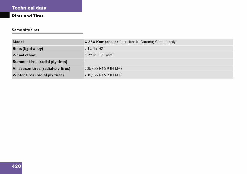
420
Technical data
Rims a
Same s
Model a only)
Rims (l
Wheel
Summe
All seas
Winter
nd Tires
ize tires
C 230 Kompressor (standard in Canada; Canad
ight alloy) 7 J x 16 H2
offset 1.22 in (31 mm)
r tires (radial-ply tires) -
on tires (radial-ply tires) 205/55 R16 91H M+S
tires (radial-ply tires) 205/55 R16 91H M+S
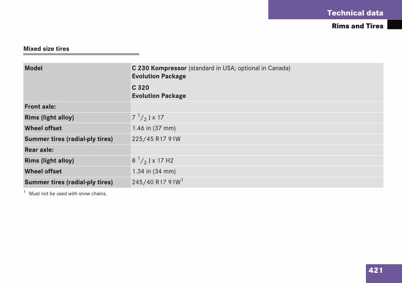
421
Technical data
Rims and Tires
Mixed
Mode Canada)
Front
Rims
Whee
Summ
Rear a
Rims
Whee
Summ1 Must
size tires
l C 230 Kompressor (standard in USA; optional in Evolution Package
C 320Evolution Package
axle:
(light alloy) 7 1/2 J x 17
l offset 1.46 in (37 mm)
er tires (radial-ply tires) 225/45 R17 91W
xle:
(light alloy) 8 1/2 J x 17 H2
l offset 1.34 in (34 mm)
er tires (radial-ply tires) 245/40 R17 91W1
not be used with snow chains.
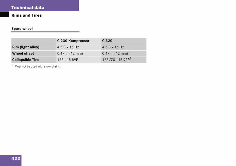
422
Technical data
Rims a
Spare w
Rim (lig
Wheel
Collaps1 Must no
nd Tires
heel
C 230 Kompressor C 320
ht alloy) 4.5 B x 15 H2 4.5 B x 16 H2
offset 0.47 in (12 mm) 0.47 in (12 mm)
ible Tire 165 - 15 89P1 165/70 - 16 92P1
t be used with snow chains.
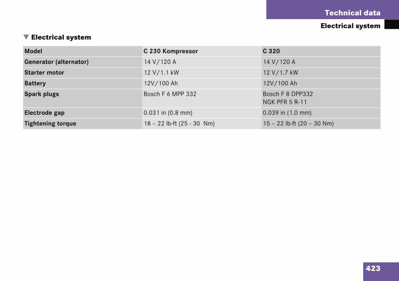
423
Technical data
Electrical system
�
M 320
Ge 4 V/120 A
St 2 V/1.7 kW
Ba 2V/100 Ah
Sp osch F 8 DPP332GK PFR 5 R-11
El .039 in (1.0 mm)
Ti 5 – 22 lb-ft (20 – 30 Nm)
Elect
odel
nerato
arter m
ttery
ark pl
ectrod
ghtenin
rical system
C 230 Kompressor C
r (alternator) 14 V/120 A 1
otor 12 V/1.1 kW 1
12V/100 Ah 1
ugs Bosch F 6 MPP 332 BN
e gap 0.031 in (0.8 mm) 0
g torque 18 – 22 lb-ft (25 - 30 Nm) 1

Technical data
D
l
ll
ll
ll
lb
, f
, r
424
Main
Mode
Overa
Overa
Overa
Whee
Track
Track
imensions
C 230 KompressorC 320
vehicle length 171.2 in (4348 mm)
vehicle width 68.0 in (1728 mm)
vehicle height 55.4 in (1406 mm)
ase 106.9 in (2715 mm)
ront 59.2 in (1505 mm)
ear 58.1 in (1476 mm)

425
Technical data
Weights
�
Ro
Tr
Weig
of load
unk lo
hts
max. 220 lb (100 kg)
ad max. 220 lb (100 kg)
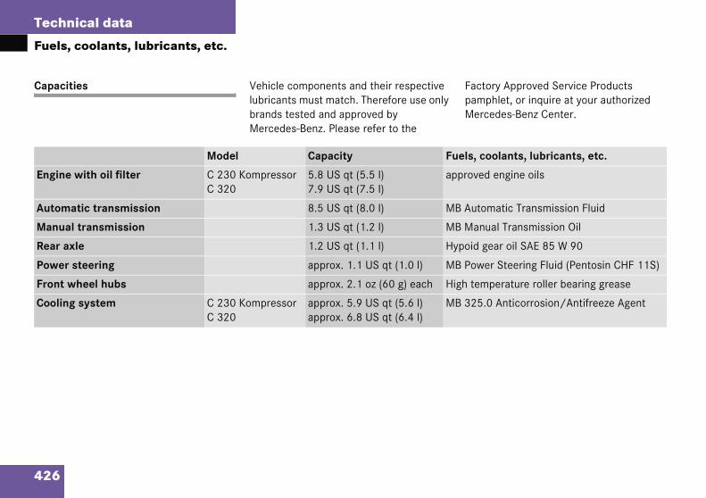
Technical data
,
it actory Approved Service Products amphlet, or inquire at your authorized ercedes-Benz Center.
, coolants, lubricants, etc.
e ved engine oils
a utomatic Transmission Fluid
a anual Transmission Oil
x id gear oil SAE 85 W 90
r ower Steering Fluid (Pentosin CHF 11S)
w temperature roller bearing grease
g 25.0 Anticorrosion/Antifreeze Agent
426
Fuels
Capac
Engin
Autom
Manu
Rear a
Powe
Front
Coolin
coolants, lubricants, etc.
ies Vehicle components and their respective lubricants must match. Therefore use only brands tested and approved by Mercedes-Benz. Please refer to the
FpM
Model Capacity Fuels
with oil filter C 230 KompressorC 320
5.8 US qt (5.5 l)7.9 US qt (7.5 l)
appro
tic transmission 8.5 US qt (8.0 l) MB A
l transmission 1.3 US qt (1.2 l) MB M
le 1.2 US qt (1.1 l) Hypo
steering approx. 1.1 US qt (1.0 l) MB P
heel hubs approx. 2.1 oz (60 g) each High
system C 230 KompressorC 320
approx. 5.9 US qt (5.6 l)approx. 6.8 US qt (6.4 l)
MB 3

427
Technical data
Fuels, coolants, lubricants, etc.
ts, lubricants, etc.
Fuel tinclud
ded gasoline:ed Octane 91 (Avg. of 96 RON/86 MON)
ehicles (identified by a label reading oline or E85 only! on fuel filler flap):l: Ethanol fuel (E85)
Air co rant and special PAG lubricant oil
Winds Washer Concentrate1
Windsheadl
1 Use M Washer Concentrate “S” and commercially availablepremi g ratios (� page 435).
Model Capacity Fuels, coolan
anking a reserve of
16.4 US gal (62.0 l)2.1 US gal (8.0 l)
Premium unleaMinimum Post
Flexible Fuel VPremium gasAlternative fue
nditioning system R-134a refrige(never R-12)
hield washer 3.2 US qt (3.0 l) MB Windshield
hield washer and amp cleaning system*
6.4 US qt (6.0 l)
B Windshield Washer Concentrate “S” and water for temperatures above freezing point or MB Windshieldxed windshield washer solvent/antifreeze for temperatures below freezing point. Follow suggested mixin

428
Technical data
Fuels,
Engine
Engine osuitabilitour servapprovequired foSystem vehiclesoils and Approvecontact Center.
Using ention othefor the Mvehicleschanginvals longMaintenFSS (CadamageMercede
rake fluid
uring vehicle operation, the boiling point f the brake fluid is continuously reduced rough the absorption of moisture from e atmosphere. Under extremely strenu-
us operating conditions, this moisture ontent can lead to the formation of bub-les in the system, thus reducing the sys-m’s efficiency.
herefore, the brake fluid must be re-laced every two years, preferably in the pring.
nly brake fluid approved by ercedes-Benz is recommended. An
uthorized Mercedes-Benz Center will rovide you with additional information.
coolants, lubricants, etc.
oils
ils are specifically tested for their y in our engines and durability for ice intervals. Therefore, only use d engine oils and oil filters re-r vehicles with Maintenance
(U.S. vehicles) or FSS (Canada ). For a listing of approved engine oil filters, refer to the Factory d Service Products pamphlet, or an authorized Mercedes-Benz
gine oils and oil filters of specifica-r than those expressly required aintenance System (U.S.
) or FSS (Canada vehicles), or g of oil and oil filter at change inter-er than those called for by the
ance System (U.S. vehicles) or nada vehicles) will result in engine not covered by the s-Benz Limited Warranty
Please follow Maintenance System (U.S. vehicles) or FSS (Canada vehicles) recom-mendations for scheduled oil changes. Failure to do so will result in engine dam-age not covered by the Mercedes-Benz Limited Warranty.
Engine oil additives
Do not blend oil additives with engine oil. They may damage the engine.
Damage or malfunctions resulting from blending oil additives are not covered by the Mercedes-Benz Limited Warranty.
Air conditioning refrigerant
R-134a (HFC) refrigerant and special PAG lubricating oil is used in the air condition-ing system.
Never use R-12 (CFC) or mineral-based lubricating oil. Otherwise damage to the system will occur.
B
Doththocbte
Tps
OMap
429
Technical data
Fuels, coolants, lubricants, etc.
Premi Unleaded gasoline containing oxygenates such as Ethanol, IPA, IBA and TBA can be used provided the ratio of any one of these oxygenates to gasoline does not exceed 10%; MTBE must not exceed 15%.
The ratio of Methanol to gasoline must not exceed 3% plus additional cosolvents.
Using mixtures of Ethanol and Methanol is not allowed. Gasohol, which contains 10% Ethanol and 90% unleaded gasoline, can be used.
These blends must also meet all other fuel requirements, such as resistance to spark knock, boiling range, vapor pressure, etc.
!To perlineis nuse
�
�
�
�
um unleaded gasoline Fuel requirements
Use only premium unleaded fuel meeting ASTM standard D 439:
� The octane number (posted at the pump) must be 91 min. It is an average of both the Research (R) octane num-ber and the Motor (M) octane number: (R+M)/2). This is also known as the ANTI-KNOCK INDEX.
maintain the engine’s durability and formance, premium unleaded gaso- must be used. If premium unleaded ot available and low octane fuel is d, follow these precautions:
Have the fuel tank only partially filled with unleaded regular and fill up with premium unleaded as soon as possible.
Avoid full throttle driving and abrupt acceleration.
Do not exceed an engine speed of 3000 rpm if the vehicle is loaded with a light load such as two per-sons and no luggage.
Do not exceed 2/3 of maximum ac-celerator pedal position if the vehi-cle is fully loaded or operating in mountainous terrain.
iFlexible Fuel Vehicles (identified by a label reading Premium gasoline or E85 only! on fuel filler flap) are de-signed to operate on premium unlead-ed gasoline or Ethanol fuel (E85), or any mixture of these two.
For more information, see “Flexible Fuel Vehicles” (� page 431).

430
Technical data
Fuels,
Gasolin
A majorturers isline. Meuse of quthat preits.
After anwithout can buildand in thengine p
� Warm
� Unst
� Knoc
� Misf
� Powe
o not blend any specific fuel additives ith fuel. This only results in unnecessary ost and may be harmful to engine opera-on.
amage or malfunction resulting from oor fuel quality or from blending addition-l fuel additives other than those tested nd approved by us for use on ercedes-Benz vehicles listed in the
actory Approved Service Products amphlet are not covered by the ercedes-Benz Limited Warranty.
coolants, lubricants, etc.
e additives
concern among engine manufac- carbon build-up caused by gaso-rcedes-Benz recommends only the ality gasoline containing additives
vent the build-up of carbon depos-
extended period of using fuels such additives, carbon deposits up especially on the intake valves e combustion area, leading to erformance problems such as:
-up hesitation
able idle
king/pinging
ire
r loss
In areas where carbon deposits may be encountered due to lack of availability of gasolines which contain these additives, Mercedes-Benz recommends the use of additives approved by us for use on Mercedes-Benz vehicles. Refer to Factory Approved Service Products Pamphlet for a listing of approved product(s). Follow directions on product label.
Dwcti
DpaaMFpM

431
Technical data
Fuels, coolants, lubricants, etc.
Flexib
Flexibllabel reonly! o
These premiu(E85),
Ethanomatelygasolin
If in spite of these recommendations the engine does not perform properly, adding more gasoline (at least 3 gallons [12 liters]) to the fuel may improve the engine behavior.
Cold weather performance
It is possible that starting times will signif-icantly increase at temperatures below 32°F (0°C). At low temperatures the use of a block heater is recommended (see an authorized Mercedes-Benz Center for further information). Rough idling may also be experienced at such temperatures before the engine is fully warmed up.
Warn
Ethanflammnol fuor if yfumesfumesguish smok
!E85 fuel is unsuitable for use when am-bient temperatures fall below 14°F (-10°C).
le Fuel Vehicles
e Fuel Vehicles are identified by a ading Premium gasoline or E85 n fuel filler flap).
vehicles are designed to operate on m unleaded gasoline or Ethanol fuel or on any mixture of these two.
l fuel (E85) is a mixture of approxi- 85% Ethanol and 15% unleaded e.
Switching fuels
For best performance and driveability it is recommended to use either one or the oth-er fuel. A refueling pattern that alternates between the two different fuels should be avoided if possible.
When switching fuels, make sure:
� Fuel level is below half full.
� Fuel level is above reserve (reserve warning lamp is not lit).
� Amount of added fuel is more than 5 gallons (20 liters).
� Ignition is off during refill.
� Immediately after refueling engine is started and operated for at least five minutes.
These precautions and recommendations are supposed to prevent any difficulties when starting and operating the engine which otherwise may be experienced before the engine has fully adapted to the different fuel.
ing! G
ol fuel (E85) and its fumes are highly able, poisonous and burn easily. Etha-
el can cause serious injuries if ignited ou come into contact with it or inhale of it. Avoid inhalation of Ethanol and skin contact with Ethanol. Extin-all open flames before fueling. Never e or create sparks close to Ethanol.
432
Technical data
Fuels,
Hot wea
At ambie(35°C) saccompstart.
Cruising
E85 fuelthan gasformancthat wheburn mobe expecincreasegasoline
Mainten
Please inMercedeused E8ered for
he coolant solution must be used ear-round to provide the necessary corro-ion protection and increase boil-over pro-ction. Refer to Maintenance Booklet for placement interval.
oolant system design and coolant used etermine the replacement interval. The placement interval published in the aintenance Booklet is only applicable if B 325.0 anticorrosion/antifreeze solu-on or other Mercedes-Benz approved roducts of equal specification (see Facto- Approved Service Products pamphlet)
re used to renew the coolant concentra-on or bring it back up to the proper level.
o provide important corrosion protection, e solution must be at least 45% anticor-sion/antifreeze (equivalent to freeze
rotection to approximately - 22°F 30°C]).
iUse rang
coolants, lubricants, etc.
ther performance
nt temperatures above 95°F tart times may increase and be anied by a rough idle following the
range
contains less energy per gallon oline. To ensure that engine per-e with Ethanol fuel is similar to n using gasoline, the engine must re Ethanol fuel. As a result, it is to ted that the fuel consumption will when using E85 compared to operation.
ance
form your authorized s-Benz Center if you use or have
5 fuel when your vehicle is deliv- maintenance or repairs.
Coolants
The engine coolant is a mixture of water and anticorrosion/antifreeze, which provides:
� Corrosion protection
� Freeze protection
� Boiling protection (by increasing the boiling point)
The cooling system was filled at the factory with a coolant providing freeze protection to approximately -22°F (-30°C) and corro-sion protection.
If the antifreeze mixture is effective to -22°F (-30°C), the boiling point of the cool-ant in the pressurized cooling system is reached at approximately 266°F (130°C).
Tystere
CdreMMtipryati
Tthrop[-
of E85 may reduce your driving e.

433
Technical data
Fuels, coolants, lubricants, etc.
If you uanticortion toenginethe lowlution. this am
If the cMB 32be use(have cleakagin acco
The waminimusatisfieare notsult an
Before the start of the winter season (or once a year in hot southern regions), you should have the anticorrosion/antifreeze concentration checked. The coolant is also regularly checked each time you bring your vehicle to an authorized Mercedes-Benz Center for service.
se a solution that is more than 55% rosion/antifreeze (freeze protec- approximately - 49°F [-45°C]), the temperature will increase due to er heat transfer capability of the so-Therefore, do not use more than ount of anticorrosion/antifreeze.
oolant level is low, water and 5.0 anticorrosion/antifreeze should d to bring it up to the proper level ooling system checked for signs of
e). Please make sure the mixture is rdance with label instructions.
ter in the cooling system must meet m requirements, which are usually d by normal drinking water. If you sure about the water quality, con- authorized Mercedes-Benz Center.
Anticorrosion/antifreeze
Your vehicle contains a number of alumi-num parts. The use of aluminum compo-nents in motor vehicle engines necessitates that anticorrosion/antifreeze coolant used in such engines be specifical-ly formulated to protect the aluminum parts. (Failure to use such anticorro-sion/antifreeze coolant will result in a significantly shortened service life.)
Therefore, the following product is strongly recommended for use in your vehicle: Mercedes-Benz 325.0 Anticorrosion/Anti-freeze agent.

434
Technical data
Fuels,
Anticorr
Model
C 230 K
C 320
coolants, lubricants, etc.
osion/antifreeze quantity
Approx. freeze protection
–35°F (–37°C) –49°F (–45°C)
ompressor 3.0 US qt (2.8 l) 3.3 US qt (3.1 l)
3.4 US qt (3.2 l) 3.8 US qt (3.6 l)

435
Technical data
Fuels, coolants, lubricants, etc.
Windsheadla
Both thsystemwashe
The waapprox
� 6.4lam
� 3.2hea
Windshield and headlamp washer fluid mixing ratio
For temperatures above freezing point, use MB Windshield Washer Concentrate “S” and water:
� 1 part “S” to 100 parts water
[40 ml “S” to 1 gallon (4 liters) water]
For temperatures below freezing point, use MB Windshield Washer Concentrate “S” and commercially available premixed windshield washer solvent/antifreeze:
� 1 part “S” to 100 parts solvent
[40 ml “S” to 1 gallon (4 liters) solvent].
hield washer system and mp cleaning system
e windshield and headlamp washer s are supplied from the windshield
r fluid reservoir.
sher fluid reservoir has a capacity of imately
US qt (6.0 l) in vehicles with head-p cleaning system*
US qt (3.0 l) in vehicles without dlamp cleaning system
� Refill the reservoir with MB Windshield Washer Concentrate and water (or con-centrate and commercially available premixed windshield washer sol-vent/antifreeze, depending on ambient temperatures).
Warning! G
Washer solvent/antifreeze is highly flamma-ble. Do not spill washer solvent/antifreeze on hot engine parts, because it may ignite and burn. You can be seriously burned.

436
Technical terms
ABS(AnPredurcon
Acces(�
Air pre(�
Alignm
CockpitAll instruments, switches, buttons and indicator/warning lamps in the passen-ger compartment needed for vehicle operation and monitoring.
Cold tire inflation pressure(� page 323)
Collapsible tireAn especially compact spare tire that must be inflated with a provided air
437
Mepinto a
Aspec(�
Bar(�
BAS(BrSysdistionsenfas
pump before using. It should only be used to bring the vehicle to the nearest service station.
COMAND*(Cockpit Management and Data Sys-tem)Information and operating center for vehicle sound and communications systems, including the radio and navi-gation system, as well as other optional equipment (CD changer, telephone, etc.).
tilock Brake System)vents the wheels from locking up ing braking so that the vehicle can tinue to be steered.
sory weightpage 323)
ssurepage 323)
ent bolttal pin with thread. The centering is an aid used when changing a tire lign the wheel with the wheel hub.
t ratiopage 323)
page 323)
ake Assist System)tem for potentially reducing braking
tances in emergency braking situa-s. The system is activated when it ses an emergency based on how t the brake is applied.
Bead(� page 323)
Bi-Xenon headlamps*Headlamps which use an electric arc as the light source and produce a more in-tense light than filament headlamps. Bi-Xenon headlamps produce low beam and high beam.
CAC(Customer Assistance Center)Mercedes-Benz customer service cen-ter, which can help you with any ques-tions about your vehicle and provide assistance in the event of a break-down.
CAN system(Controller Area Network)Data bus network serving to control ve-hicle functions such as door locking or windshield wiping.
438
Technical terms
ControlThe cvehiccommessdisplthe mnavigjust
Cruise cDrivimatiset b
Curb we(� pa
DOT(Dep(� pa
Engine The nand uniqduce
SS (Canada vehicles)(Flexible Service System)Maintenance service indicator in the multifunction display that informs the driver when the next vehicle mainte-nance service is due. FSS evaluates engine temperature, oil level, vehicle speed, engine speed, distance driven and the time elapsed since your last maintenance service, and calls for the next maintenance service accordingly.
AWR(Gross Axle Weight Rating)(� page 323)
ear rangeNumber of gears which are available to the automatic transmission for shifting. The automatic gear shifting process can be adapted to specific operating conditions using the gear selector le-ver.
systemontrol system is used to call up le information and to change
ponent settings. Information and ages appear in the multifunction ay. The driver uses the buttons on ultifunction steering wheel to ate through the system and to ad-
settings.
ontrolng convenience system for auto-cally maintaining the vehicle speed y the driver.
ightge 323)
artment of Transportation)ge 323)
numberumber set by the manufacturer
placed on the cylinder block to uely identify each engine pro-d.
Engine oil viscosityMeasurement for the inner friction (vis-cosity) of the oil at different tempera-tures. The higher the temperature an oil can tolerate without becoming thin, or the lower the temperature it can tol-erate without becoming viscous, the better the viscosity.
ESP(Electronic Stability Program)Improves vehicle handling and direc-tional stability.
ETD(Emergency Tensioning Device)Device which deploys in certain frontal and rear collisions exceeding the sys-tem's threshold to tighten the seat belts.->SRS
F
G
G
439
Technical terms
GPS*(GloSatgeofromceinav
GVW(Gr(�
GVWR(Gr(�
InstruThelamcluand
Maximum load rating(� page 324)
Maximum loaded vehicle weight(� page 324)
Maximum tire inflation pressure(� page 324)
Memory function*Used to store three individual seat, steering wheel and mirror positions for each SmartKey.
MON(Motor Octane Number)The Motor Octane Number for gasoline as determined by a standardized meth-od. It is an indication of a gasoline's ability to resist undesired detonation (knocking). The average of both the MON (Motor Octane Number) and ->RON (Research Octane Number) is posted at the pump, also known as ANTI-KNOCK INDEX.
bal Positioning System)ellite-based system for relaying graphic location information to and vehicles equipped with special re-
vers. Employs CD digital maps for igation.
oss Vehicle Weight)page 324)
oss Vehicle Weight Rating)page 324)
ment cluster displays and indicator/warning ps in the driver’s field of vision, in-
ding the tachometer, speedometer fuel gauge.
KickdownDepressing the accelerator past the point of resistance shifts the transmis-sion down to the lowest possible gear. This very quickly accelerates the vehi-cle and should not be used for normal acceleration needs.
Kilopascal (kPa)(� page 324)
Lock buttonButton on the door which indicates whether the door is locked or un-locked. Pushing the lock button down on an individual door from inside will lock that door.
Maintenance System (U.S. vehicles)Maintenance service indicator in the multifunction display that informs the driver when the next vehicle mainte-nance service is due. The Maintenance System in your vehicle tracks distance driven and the time elapsed since your last maintenance service, and calls for the next maintenance service accord-ingly.
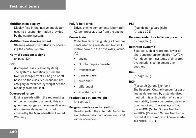
440
Technical terms
MultifuDispusedby th
MultifuSteeing t
Normal(� pa
OCS(OccThe sfrontbasecateread
OverspeEngiof thgine riouscoveWarr
SI(Pounds per square inch)(� page 325)
ecommended tire inflation pressure(� page 325)
estraint systemsSeat belts, child restraints, lower an-chors and tethers for children (LATCH). As independent systems, their protec-tive functions complement one another.
im(� page 325)
ON(Research Octane Number)The Research Octane Number for gaso-line as determined by a standardized method. It is an indication of a gaso-line's ability to resist undesired detona-tion (knocking). The average of both the ->MON (Motor Octane Number) and RON (Research Octane Number) is posted at the pump, also known as AN-TI-KNOCK INDEX.
nction displaylay field in the instrument cluster to present information provided e control system.
nction steering wheelring wheel with buttons for operat-he control system.
occupant weightge 324)
upant Classification System) ystem automatically turns the passenger front air bag on or off d on the classified occupant size gory determined by weight sensor ings from the seat.
ed rangene speeds within the red marking e tachometer dial. Avoid this en-speed range, as it may result in se- engine damage that is not red by the Mercedes-Benz Limited anty.
Poly-V-belt driveDrives engine-components (alternator, AC compressor, etc.) from the engine.
Power trainCollective term designating all compo-nents used to generate and transmit motive power to the drive axles, includ-ing
� engine
� clutch/torque converter
� transmission
� transfer case
� drive shaft
� differential
� axle shafts/axles
Production options weight(� page 324)
Program mode selector switchUsed to switch the automatic transmis-sion between standard operation S and winter operation C.
P
R
R
R
R

441
Technical terms
Shift lWhprebeiSmpre
Sidew(�
SRS(SuAir cradevtheeffe
Tire ply composition and material used(� page 325)
Tire speed rating(� page 325)
Traction(� page 325)
Tread(� page 325)
Treadwear indicators(� page 325)
Uniform Tire Quality Grading Standards(� page 326)
Vehicle capacity weight(� page 326)
Vehicle maximum load on the tire(� page 326)
VIN(Vehicle Identification Number)The number set by the manufacturer and placed on the body to uniquely identify each vehicle produced.
ocken the vehicle is parked, this lock vents the gear selector lever from ng moved out of position P without artKey turned and brake pedal de-ssed.
allpage 325)
pplemental Restraint System)bags, air bag control unit (with sh sensor), emergency tensioning ice. Though independent systems, y are closely interfaced to provide ctive occupant protection.
Tele Aid* System(Telematic Alarm Identification on De-mand)The Tele Aid system consists of three types of response: automatic and man-ual emergency, roadside assistance and information. Tele Aid is initially activated by completing a subscriber agreement and placing an acquain-tance call.The Tele Aid system is operational pro-vided that the vehicle’s battery is charged, properly connected, not dam-aged and cellular and GPS coverage is available.
Tightening torqueForce times lever arm (e.g. a lug wrench) with which threaded fasteners such as wheel bolts are tightened.
TIN(Tire Identification Number)(� page 325)
Tire load rating(� page 325)

442
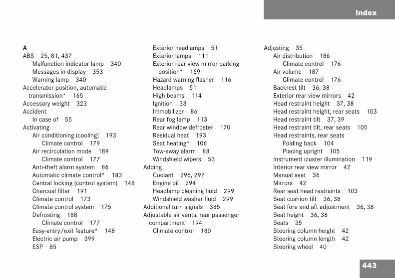
Index
AABS
MaMeWa
Acceletrans
AccessAccide
In cActivat
Adjusting 35Air distribution 186
Climate control 176Air volume 187
Climate control 176Backrest tilt 36, 38Exterior rear view mirrors 42Head restraint height 37, 38Head restraint height, rear seats 103Head restraint tilt 37, 39Head restraint tilt, rear seats 105
443
Air
Air
AntAutCenChaClimClimDef
EasEleESP
Head restraints, rear seatsFolding back 104Placing upright 105
Instrument cluster illumination 119Interior rear view mirror 42Manual seat 36Mirrors 42Rear seat head restraints 103Seat cushion tilt 36, 38Seat fore and aft adjustment 36, 38Seat height 36, 38Seats 35Steering column height 42Steering column length 42Steering wheel 40
25, 81, 437lfunction indicator lamp 340ssages in display 353rning lamp 340rator position, automatic mission* 165ory weight 323ntase of 55ingconditioning (cooling) 193Climate control 179recirculation mode 189Climate control 177i-theft alarm system 86omatic climate control* 183tral locking (control system) 148rcoal filter 191ate control 173ate control system 175
rosting 188Climate control 177y-entry/exit feature* 148ctric air pump 399
85
Exterior headlamps 51Exterior lamps 111Exterior rear view mirror parking
position* 169Hazard warning flasher 116Headlamps 51High beams 114Ignition 33Immobilizer 86Rear fog lamp 113Rear window defroster 170Residual heat 193Seat heating* 106Tow-away alarm 88Windshield wipers 53
AddingCoolant 296, 297Engine oil 294Headlamp cleaning fluid 299Windshield washer fluid 299
Additional turn signals 385Adjustable air vents, rear passenger
compartment 194Climate control 180
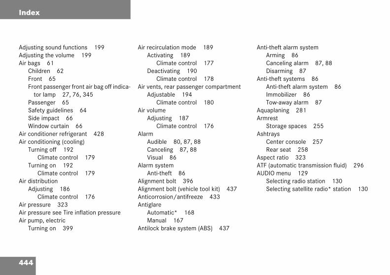
444
Index
AdjustinAdjustinAir bags
ChildFronFron
torPassSafeSideWind
Air condAir cond
TurnC
TurnC
Air distrAdju
CAir pressAir pressAir pum
Turn
nti-theft alarm systemArming 86Canceling alarm 87, 88Disarming 87
nti-theft systems 86Anti-theft alarm system 86Immobilizer 86Tow-away alarm 87
quaplaning 281rmrest
Storage spaces 255shtrays
Center console 257Rear seat 258
spect ratio 323TF (automatic transmission fluid) 296UDIO menu 129
Selecting radio station 130Selecting satellite radio* station 130
g sound functions 199g the volume 199
61ren 62t 65t passenger front air bag off indica- lamp 27, 76, 345enger 65ty guidelines 64 impact 66ow curtain 66itioner refrigerant 428itioning (cooling)ing off 192limate control 179ing on 192limate control 179
ibutionsting 186limate control 176ure 323ure see Tire inflation pressure
p, electricing on 399
Air recirculation mode 189Activating 189
Climate control 177Deactivating 190
Climate control 178Air vents, rear passenger compartment
Adjustable 194Climate control 180
Air volumeAdjusting 187
Climate control 176Alarm
Audible 80, 87, 88Canceling 87, 88Visual 86
Alarm systemAnti-theft 86
Alignment bolt 396Alignment bolt (vehicle tool kit) 437Anticorrosion/antifreeze 433Antiglare
Automatic* 168Manual 167
Antilock brake system (ABS) 437
A
A
AA
A
AAA

445
Index
Audio sAudButCDOpOpOpRadSwSwTel
Auto-dAutom
Acts
AutomActAdjAir DeaDefSet
AutomAutom
ActDea
BBackrest
Folding forward 251Folding rearward 251
Backup lampsBulbs 384
Bar 323BAS 82, 437
Messages in display 354Batteries, SmartKey
Check lamp 93Checking 93Replacing 382, 383
Battery dischargedJump starting 404
Battery, vehicle 297, 401Charging 402Disconnecting 402Reconnecting 403Reinstalling 402Removing 402
Bead 323Bi-Xenon headlamps* 437Bi-Xenon type*
Front lamp bulbs 388Block heater 329
ystem 195io and telephone, operation 195ton and soft key operation 198* operation 213erating and display elements 196erating safety 195eration 198io operation 203
itching off 199itching on 198ephone* operation 220imming* for rear view mirror 168atic central lockingivating/deactivating (control ystem) 148atic climate control* 182ivating 183usting air distribution 186recirculation mode 189ctivating 183rosting 188ting the temperature 185atic headlamp mode 111atic lighting controlivating 117ctivating 117
Automatic locking when driving 97Automatic shift program*
Program mode selector switch 164Automatic time change
(summer-/winter) 141Automatic transmission* 159, 296
Accelerator position 165Automatic shift program 164Comfort program mode 164Emergency operation (Limp Home
Mode) 166Fluid level 296Gear ranges 161Gear selector lever 159Gear selector lever position 159, 162Gear shifting malfunctions 166Kickdown 165Manual shifting 160One-touch gearshifting 160Program mode selector switch 164Starting with 49Transmission fluid 296Working on the vehicle 165
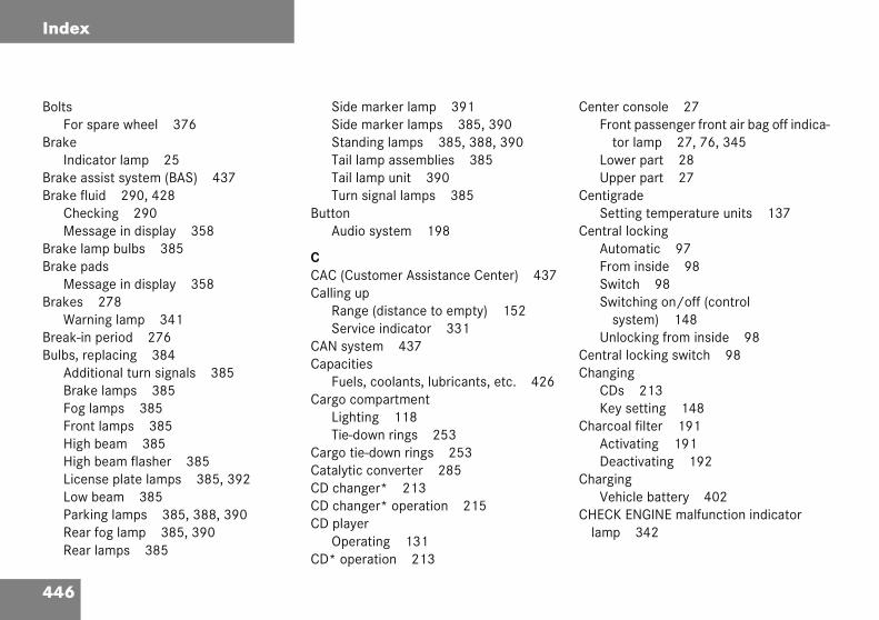
446
Index
BoltsFor s
BrakeIndic
Brake asBrake flu
ChecMess
Brake laBrake pa
MessBrakes
WarnBreak-inBulbs, re
AddiBrakFog FronHighHighLicenLow ParkRearRear
enter console 27Front passenger front air bag off indica-
tor lamp 27, 76, 345Lower part 28Upper part 27
entigradeSetting temperature units 137
entral lockingAutomatic 97From inside 98Switch 98Switching on/off (control
system) 148Unlocking from inside 98
entral locking switch 98hanging
CDs 213Key setting 148
harcoal filter 191Activating 191Deactivating 192
hargingVehicle battery 402
HECK ENGINE malfunction indicator lamp 342
pare wheel 376
ator lamp 25sist system (BAS) 437id 290, 428king 290age in display 358
mp bulbs 385dsage in display 358278
ing lamp 341 period 276placing 384
tional turn signals 385e lamps 385lamps 385t lamps 385 beam 385 beam flasher 385se plate lamps 385, 392
beam 385ing lamps 385, 388, 390 fog lamp 385, 390 lamps 385
Side marker lamp 391Side marker lamps 385, 390Standing lamps 385, 388, 390Tail lamp assemblies 385Tail lamp unit 390Turn signal lamps 385
ButtonAudio system 198
CCAC (Customer Assistance Center) 437Calling up
Range (distance to empty) 152Service indicator 331
CAN system 437Capacities
Fuels, coolants, lubricants, etc. 426Cargo compartment
Lighting 118Tie-down rings 253
Cargo tie-down rings 253Catalytic converter 285CD changer* 213CD changer* operation 215CD player
Operating 131CD* operation 213
C
C
C
CC
C
C
C
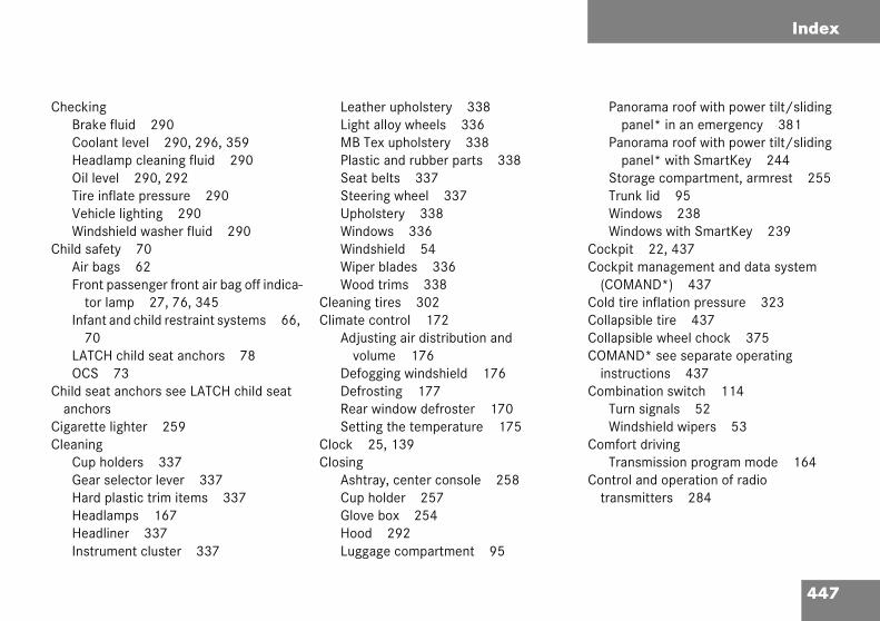
447
Index
CheckiBraCooHeaOil TireVehWin
Child sAir Fro
tInfa
7LATOC
Child sanch
CigareCleanin
CupGeaHarHeaHeaIns
Panorama roof with power tilt/sliding panel* in an emergency 381
Panorama roof with power tilt/sliding panel* with SmartKey 244
Storage compartment, armrest 255Trunk lid 95Windows 238Windows with SmartKey 239
Cockpit 22, 437Cockpit management and data system
(COMAND*) 437Cold tire inflation pressure 323Collapsible tire 437Collapsible wheel chock 375COMAND* see separate operating
instructions 437Combination switch 114
Turn signals 52Windshield wipers 53
Comfort drivingTransmission program mode 164
Control and operation of radio transmitters 284
ngke fluid 290lant level 290, 296, 359dlamp cleaning fluid 290
level 290, 292 inflate pressure 290icle lighting 290dshield washer fluid 290afety 70bags 62nt passenger front air bag off indica-or lamp 27, 76, 345nt and child restraint systems 66, 0CH child seat anchors 78
S 73eat anchors see LATCH child seat orstte lighter 259g holders 337r selector lever 337d plastic trim items 337dlamps 167dliner 337
trument cluster 337
Leather upholstery 338Light alloy wheels 336MB Tex upholstery 338Plastic and rubber parts 338Seat belts 337Steering wheel 337Upholstery 338Windows 336Windshield 54Wiper blades 336Wood trims 338
Cleaning tires 302Climate control 172
Adjusting air distribution and volume 176
Defogging windshield 176Defrosting 177Rear window defroster 170Setting the temperature 175
Clock 25, 139Closing
Ashtray, center console 258Cup holder 257Glove box 254Hood 292Luggage compartment 95

448
Index
Control AUDConvDisp
12Disp
12FuncInstr
13InterLightMenMultMultNAVSeleSeleSettiStanSubmSubmTEL*Trip Vehi
me
Fine adjustment 249Message in display 362Setting current speed 248Setting speeds 249
ruise control lever 247ruising range, fuel 432up holders 256
Cleaning 337urb weight 323ustomer Assistance Center (CAC) 437
ate (day)Setting 142
ate (month)Setting 141
ate (year)Setting 143
aytime running lamp mode 112Setting 144
system 123, 438IO menu 129enience submenu 148lay digital speedometer 128, 9lay outside temperature 128, 9tions 124, 127ument cluster submenu 137, 9ior lighting delayed shut-off 147ing submenu 144us 126, 127ifunction display 123ifunction steering wheel 124I* menu 131cting radio system 130cting satellite radio* system 130ngs menu 133dard display menu 128enu Time/Date 139enus 125, 127
menu 153computer menu 151cle status message memory nu 132
Vehicle submenu 148Convenience submenu 148
Activating easy-entry/exit feature* 148
Setting key dependency 149Setting parking position* for exterior
rear view mirror 150Coolant 296, 359, 432
Adding 296, 297Anticorrosion/antifreeze
quantity 432Capacities 426Checking level 296, 359Messages in display 359–361Refilling 296Temperature 286, 360Temperature gauge 25, 120
Coolant levelChecking 290, 296, 359
Cornering fog lamps* 114Switching off 115Switching on 115
Cruise control 247, 438Canceling 248Driving downhill 248Driving uphill 248
CCC
CC
DD
D
D
D

449
Index
DeactiAir
Air
AlaAntAutCenChaClimClimCruDefDef
ESPExtExtFroHazHeaImmReaRes
Display elementsAudio system 196
DisplaysDigital speedometer 129Engine oil 293Outside temperature 129Selecting display for status
indicator 138Service indicator 330Showing malfunctions 132Symbol messages 357Text messages 349Vehicle status messages 347
Distance to empty (range)Calling up 152
Door control panel 30Door handle 30Door unlock
With Tele Aid* 268Doors
Message in display 362Opening from inside vehicle 94Opening from outside 92Opening from the outside 92
DOT 323
vatingconditioning (cooling) 192Climate control 179recirculation mode 190Climate control 178rm 87i-theft alarm system 87omatic climate control* 183tral locking (control system) 148rcoal filter 192ate control 173ate control system 175
ise control 248rost 188rostingClimate control 177
84erior lamps 111erior lamps delayed shut-off 146nt fog lamps 146ard warning flasher 116dlamps 57obilizer 86
r window defroster 170idual heat 193
Seat heating* 106Tow-away alarm 88
Deep water see Standing water 284Defogging
Windshield 187Climate control 176
Defrosting 188Climate control 177
Delayed shut-offExterior lamps 146
Department of Transportation see DOTDialing
A number (telephone*) 154Difficulties
While driving see Problems while driving 55
With starting 49Digital speedometer 129Direction of rotation (tires) 303Discharged battery
Jump starting 404Disconnecting
Vehicle battery 402Display
Messages in display 362
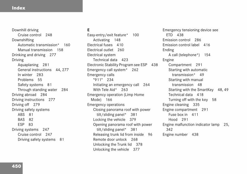
450
Index
DownhilCruis
DownshAutoMan
DrinkingDriving
AquaGeneIn wiProbSafeThro
Driving aDriving iDriving oDriving s
ABSBASESP
Driving sCruisDrivi
mergency tensioning device see ETD 438
mission control 286mission control label 416nding
A call (telephone*) 154ngine
Compartment 291Starting with automatic
transmission* 49Starting with manual
transmission 48Starting with the SmartKey 48, 49Technical data 418Turning off with the key 58
ngine cleaning 335ngine compartment 291
Fuse box in 411Hood 291
ngine malfunction indicator lamp 25, 342
ngine number 438
l drivinge control 248
iftingmatic transmission* 160ual transmission 158 and driving 277
planing 281ral instructions 44, 277nter 283lems 55ty systems 81ugh standing water 284broad 284
nstructions 277ff 279afety systems
818283
ystems 247e control 247
ng safety systems 81
EEasy-entry/exit feature* 100
Activating 148Electrical fuses 410Electrical outlet 260Electrical system
Technical data 423Electronic Stability Program see ESP 438Emergency call system* 262Emergency calls
"911" 234Initiating an emergency call 264With Tele Aid* 263
Emergency operation (Limp Home Mode) 166
Emergency operationsClosing panorama roof with power
tilt/sliding panel* 381Locking the vehicle 379Opening panorama roof with power
tilt/sliding panel* 381Releasing trunk lid from inside 96Remote door unlock 268Unlocking the Trunk lid 378Unlocking the vehicle 377
E
EEE
E
EE
E
E
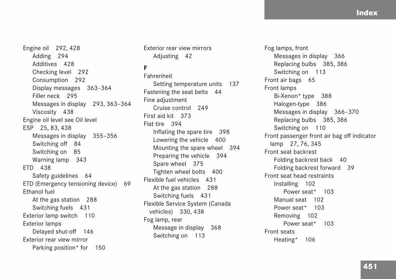
451
Index
EngineAddAddCheConDisFillMeVis
EngineESP
MeSwSwWa
ETDSaf
ETD (EEthano
At tSw
ExterioExterio
DelExterio
Par
Fog lamps, frontMessages in display 366Replacing bulbs 385, 386Switching on 113
Front air bags 65Front lamps
Bi-Xenon* type 388Halogen-type 386Messages in display 366–370Replacing bulbs 385, 386Switching on 110
Front passenger front air bag off indicator lamp 27, 76, 345
Front seat backrestFolding backrest back 40Folding backrest forward 39
Front seat head restraintsInstalling 102
Power seat* 103Manual seat 102Power seat* 103Removing 102
Power seat* 103Front seats
Heating* 106
oil 292, 428ing 294itives 428cking level 292sumption 292
play messages 363–364er neck 295ssages in display 293, 363–364cosity 438 oil level see Oil level25, 83, 438ssages in display 355–356itching off 84itching on 85rning lamp 343438ety guidelines 64mergency tensioning device) 69l fuelhe gas station 288itching fuels 431r lamp switch 110r lampsayed shut-off 146r rear view mirrorking position* for 150
Exterior rear view mirrorsAdjusting 42
FFahrenheit
Setting temperature units 137Fastening the seat belts 44Fine adjustment
Cruise control 249First aid kit 373Flat tire 394
Inflating the spare tire 398Lowering the vehicle 400Mounting the spare wheel 394Preparing the vehicle 394Spare wheel 375Tighten wheel bolts 400
Flexible fuel vehicles 431At the gas station 288Switching fuels 431
Flexible Service System (Canada vehicles) 330, 438
Fog lamp, rearMessage in display 368Switching on 113

452
Index
FSS seevehicl
Fuel 2AddiCruisE85 Fuel GasoPrem
42RequReseSwitTech
Fuel addFuel cap
MessFuel con
AfterSinc
Fuel filleLockOpenUnlo
arage door opener* 29, 269asoline
Gasoline additives 430asoline see Fuel 289AWR 323ear range 438
Automatic transmission* 161Limiting 161Shifting into optimal 161
ear range limitCanceling 161
ear selector lever 25, 159Cleaning 337Position (Automatic
transmission*) 25, 159, 162lobal
Locking 92Unlocking 92
lobal Positioning System (GPS) 439love box 23, 254
Closing 254Opening 254
ood visibility 167PS 439ross Axle Weight Rating see GAWR
Flexible Service System (Canada es)89tives 430ing range 432
(Ethanol fuel) 432reserve warning lamp 344line additives 430ium unleaded gasoline 289, 7, 429irements 429rve warning 25ching (Flexible fuel vehicle) 431nical data 426itives 430
age in display 365sumption statistics start 151e last reset 151r flap 288ing 288ing in an emergency 379
cking 288
Fuel tankCapacity 427Filler flap 288
Fuels, coolants, lubricants etc.Capacities 426
Functions (control system) 124, 127Resetting 135
Fuse box 411In trunk 412
Fuse chart 410Fuse extractor 410, 412Fuses 410
Aid for changing 410Fuse box in engine compartment 411Fuse box in passenger
compartment 411Fuse box in trunk 412Fuse chart 410Fuse extractor 410, 412
GGG
GGG
G
G
G
GG
GGG

453
Index
Gross Gross GVWGVWR
HHaloge
FroHandsHard p
CleHazard
SwSw
Head rFro
MaPowRea
HeadlaChe
HeadlaRef
High mounted brake lamp 385Hood 291
Closing 292Message in display 365Opening 291
Hydroplaning see Aquaplaning 281
IIdentification labels 416Ignition 33
Switching on 48, 49Immobilizer 86
Activating 86Deactivating 86
Indicator lamps see Lamps, indicator and warning
Infant and child restraint systems 70Installing 77LATCH child seat anchors 78
InflatingSpare tire 398
InformationButton for Tele Aid* 266
InstallingInfant and child restraint systems 77Towing eye bolt 409Wiper blades 393
Vehicle Weight Rating see GVWRVehicle Weight see GVW324
324
n-typent lamp bulbs 386-free microphone* 29lastic trim itemsaning 337 warning flasher 116itching off 116itching on 116estraintsnt seats 37, 102Manual seat 102Power seat* 103nual seat 37, 102er seat* 38, 102r seats 103mp cleaning fluidcking 290mp cleaning system*illing 299
HeadlampsAutomatic control 111Bi-Xenon* 437Bi-Xenon* type
Replacing bulbs 388Cleaning system* 167Halogen-type
Replacing bulbs 386Refilling washer fluid 299Switching off 57Switching on 51Washer fluid* 435Washer system* 435
HeadlinerCleaning 337
Heated seats* 106Height adjustment
Head restraints 37, 38Rear seat head restraints 103Seat belts 46
High beam flasher 114High beam headlamps
Messages in display 367Replacing bulbs 385, 387
Bi-Xenon-type 389Switching on 114

454
Index
InstrumeCleaCoolIllumLamMultOutsSele
InstrumeInstrumeInterior
ActivDeacDela
syMan
Interior AdjuAntig
Interior ArmrCup
Intermit
abels, identification 416amp bulbs, exterior 384amps, exterior
Front 385Light sensor 367Messages in display 366–370Rear 385
amps, indicator and warningABS 340Air bag Off 66Battery (SmartKey) 92Brake 25Brakes 341CHECK ENGINE 342Engine diagnostics 342, 344ESP 343Fuel reserve 344Instrument cluster 343–344Low beam 25Seat belts 344Service indicator 330SRS 61, 344
anguageMultifunction display 138Setting 138
nt cluster 24, 119, 439ning 337ant temperature display 120ination 119ps in 343–344ifunction display 123ide temperature indicator 121cting language 138nt lighting 119nts and controls see Cockpit
lighting 117ating automatic control 117tivating automatic control 117yed shut-off (Control stem) 147ual operation 118rear view mirrorsting 42lare (manual) 167
storage spacesest 255holders 256tent wiping 54
JJack 373Jump starting 404
KKey dependency memory
Settings 149Key positions in starter switch 33Key, mechanical 377Key, SmartKey
Battery check lamp 92Checking the batteries 93Factory setting 92Global locking 92Global unlocking 92Loss of 94Messages in display 365Positions in starter switch 33Remote control 90Restoring to factory setting 93Selective setting 92Starting the engine 48, 49Unlocking with 32
Kickdown 165, 439Kilometers/miles in speedometer 137Kilopascal 324Km/h or mph in speedometer 137
LLLL
L
L

455
Index
LATCHFol
LayoutLeathe
CleLicens
MeRep
Light aCleTec
Light sLighterLightin
AutComDayExtFroHigInsInsInteInte
sLoc
Loss of Service and Warranty Information Booklet 415
Low beam headlampsMessages in display 368Replacing bulbs 385, 387
LoweringVehicle 400
LubricantsTechnical data 426
Luggage compartmentClosing 95Closing the lid 95Opening from inside vehicle 95Trunk lid emergency release 96
Luggage cover 252
child seat anchors 78ding back 78, 79 of poly-V-belt drive 417r upholsteryaning 338e plate lampsssages in display 367lacing bulbs 385, 392
lloy wheelsaning 336hnical data 420ensor 367 see Cigarette lighterg 110omatic headlamp mode 111bination switch 114
time running lamp mode 112erior lamp switch 110nt fog lamps 113h beams 114trument cluster illumination 119truments 119rior 117rior delayed shut-off (Control ystem) 147ator lighting 112
Low beam 110Low beam, indicator lamp 25Manual headlamp mode 111Night security illumination 112Parking lamps 110Rear fog lamp 113Settings (control system) 144
Limiting the gear range 161Limp Home Mode 166Loading 250
Cargo tie-down rings 253Instructions 252Roof rack* 250Split rear bench seat 250
Loading terminology 323Loading the vehicle 303Locator lighting 112
Setting 145Lock buttons 439Locking 56, 90
Automatic while driving 97Centrally from inside 98Fuel filler flap 288Global, SmartKey 92Vehicle in an emergency 379
Loss of keys 94
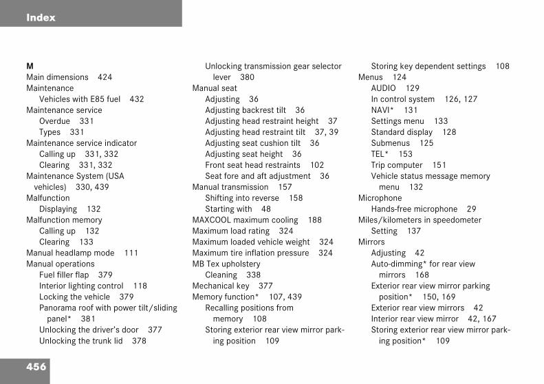
456
Index
MMain dimMainten
VehiMainten
OverType
MaintenCalliClea
Maintenvehicl
MalfuncDisp
MalfuncCalliClea
Manual Manual
Fuel InterLockPano
paUnloUnlo
Storing key dependent settings 108enus 124
AUDIO 129In control system 126, 127NAVI* 131Settings menu 133Standard display 128Submenus 125TEL* 153Trip computer 151Vehicle status message memory
menu 132icrophone
Hands-free microphone 29iles/kilometers in speedometer
Setting 137irrors
Adjusting 42Auto-dimming* for rear view
mirrors 168Exterior rear view mirror parking
position* 150, 169Exterior rear view mirrors 42Interior rear view mirror 42, 167Storing exterior rear view mirror park-
ing position* 109
ensions 424ancecles with E85 fuel 432ance servicedue 331s 331ance service indicatorng up 331, 332ring 331, 332ance System (USA es) 330, 439tionlaying 132tion memoryng up 132ring 133headlamp mode 111operationsfiller flap 379ior lighting control 118ing the vehicle 379rama roof with power tilt/sliding nel* 381cking the driver’s door 377cking the trunk lid 378
Unlocking transmission gear selector lever 380
Manual seatAdjusting 36Adjusting backrest tilt 36Adjusting head restraint height 37Adjusting head restraint tilt 37, 39Adjusting seat cushion tilt 36Adjusting seat height 36Front seat head restraints 102Seat fore and aft adjustment 36
Manual transmission 157Shifting into reverse 158Starting with 48
MAXCOOL maximum cooling 188Maximum load rating 324Maximum loaded vehicle weight 324Maximum tire inflation pressure 324MB Tex upholstery
Cleaning 338Mechanical key 377Memory function* 107, 439
Recalling positions from memory 108
Storing exterior rear view mirror park-ing position 109
M
M
M
M

457
Index
MONMON (Mph orMultifu
DisSelSetSetSetSta
MultifuABSBASBraBraCooCruDisDoEngESPFueHooKeyLamOil
OOccupant Classification System see OCSOccupant distribution 324Occupant safety 60
Air bags 61Children and air bags 62Children in the vehicle 70Fastening the seat belt 44Front passenger front air bag off indica-
tor lamp 27, 76, 345Infant and child restraint systems 66,
70LATCH child seat anchors 78OCS 73, 440Seat belts 44, 64
OCS 73, 440Self-test 77
Odometer, main 25Oil
Adding 294Consumption 292Filler neck 295Viscosity 438
Oil levelChecking 290
289Motor Octane Number) 439 km/h in speedometer 137nction display 123, 440playing gear range 161ecting language 138ting date (day) 142ting date (month) 141ting date (year) 143ndard display 127nction display messages
353354
ke fluid 358ke pads 358lant 359–361ise control 362play 362ors 362ine oil 363–364
355–356l cap 365d 365, SmartKey 365ps, exterior 366–370363–364
Panorama roof with power tilt/sliding panel* 372
Parking brake 358Restraint system 356SRS 356Steering gear oil level 371Tele Aid* 372Telephone* 372Trunk lid 372Windshield washer fluid 372
Multifunction steering wheel 26, 124, 440
Buttons 124
NNavigation system*
Operating 131See separate COMAND* operating in-
structionsNight security illumination 112
Setting 146Normal occupant weight 324
458
Index
One-touCancDowUpsh
OpeningAshtAshtCup DoorFuel Fuel GlovHoodPano
paPano
paPano
paRolleSideStoraTrunWindWind
aintwork 334anic alarm
Panic button on SmartKey 80anorama roof with power tilt/sliding panel* 241
Closing 242, 381Closing with SmartKey 244Messages in display 372Opening 242, 381Opening with SmartKey 244Stopping 244Synchronizing 246
arcel netIn front passenger footwell 257
arking 56, 279arking brake 50, 56
Engaging 56Message in display 358Releasing 50
arking lampsReplacing bulbs 385, 388, 390Switching on 110
arking position*Exterior rear view mirror 150, 169Exterior rear view mirrors 109
ch gearshifting 160eling gear range limit 161
nshifting 160ifting 160
ray, center console 257ray, rear seat 258holders 256s from the inside 94filler flap 289filler flap manually 379e box 254
291rama roof with power tilt/sliding nel* 242, 381rama roof with power tilt/sliding nel* in an emergency 381rama roof with power tilt/sliding nel* with SmartKey 244r sunblinds* 241 windows 237ge compartment, armrest 255
k lid from the inside 95ows 237ows with SmartKey 239
OperatingAudio system 195CD player 131COMAND* see separate operating in-
structionsNavigation system* 131Radio 130Radio transmitters 284Satellite radio* 130Telephone* 153, 195, 220
Operating safetyAudio system 195
Operator’s Manual 10Ornamental moldings 335Outside temperature 129Outside temperature indicator 121Overdue maintenance service 331Overhead control panel 29Overspeed range 440
PPP
P
P
PP
P
P

459
Index
Parts sParts sPassen
FusInteIntePar
foPassenPedalsPerform
In cIn h
Phone LoaQu
Phone DiaRed
PlasticCle
PlayingCD
Poly-V-Lay
Spare wheel bolts 376Symbol messages 357Text messages 349Towing the vehicle 406Vehicle jack 374Vehicle status messages in the
display 347Vehicle tool kit 373
Premium unleaded gasoline 429Problems
While driving 55Production options weight 324Program mode selector switch 440
Automatic transmission* 164PSI 325
QQuick search
Phone book* 155
RRadio
Selecting stations 130Radio operation 203Radio transmitters
Control and operation 284
ee Parts service 414ervice 414ger compartment 284e box in 411rior lighting 117rior rear view mirror 42cel net in front passenger otwell 257ger safety see Occupant safety
277ance
old weather 431ot weather 432book*ding 154
ick search 155number*ling 154ialing 156
and rubber partsaning 338
s 216belt drive 440out 417
Positions (Memory function*)Recalling from memory 108Storing into memory 108
Potential problems associated with under-inflated and overinflated tires 312
Power assistance 277Power seat*
Adjusting backrest tilt 38Adjusting head restraint height 38Adjusting seat cushion tilt 38Adjusting seat height 38Memory function* 107Removing/installing front head
restraints 103Seat fore and aft adjustment 38
Power train 440Power washer 334Power windows 237
Side windows 237Synchronizing 240
Practical hintsFirst aid kit 373Fuses 410Lamp in center console 345Lamps in instrument cluster 340Spare wheel 375

460
Index
Range (dCalli
ReadingRear ben
FoldRear fog
BulbSwit
Rear lamRepl
Rear lamMess
Rear lamRear pas
AdjuRear pas
air venClim
Rear seaAdjuAdjuFoldInstaPlaciRemSeat
emovingSpare wheel 375Vehicle battery 402Wheel 396Wiper blades 393
eplacingBackup lamp bulbs 390Batteries (SmartKey) 382, 383Brake lamp bulbs 390Bulbs 384Front lamp bulbs 385, 386Front turn signal bulbs 388, 389High beam bulbs (xenon-type*
headlamps) 389License plate lamp bulbs 392Low beam bulbs 387Parking lamp bulbs 388, 390Rear fog lamp bulb 390Rear lamp bulbs 385, 390Rear turn signal bulbs 390Side marker lamp bulbs 390, 391Standing lamp bulbs 388, 390Wiper blades 393
eset button in the instrument cluster 134, 135
istance to empty)ng up 152 lamp 29ch seat
able 250 lamp 385
385ching on 113p bulbs
acing 390psages in display 366–370ps see Tail lampssenger compartment
stable air vents 194senger compartment, adjustable ts
ate control 180t head restraints 103
sting 103sting tilt 105ing back 104lling 105ng upright 105oving 105s 105
Rear seatsAdjusting head restraint height 103Head restraints 103
Rear view mirrors see MirrorsRear window defroster 170
Activating 170Deactivating 170
Recommended tire inflation pressure 325
ReconnectingVehicle battery 403
RefillingCoolant 296Headlamp cleaning system* 299
RefrigerantAir conditioner 428
Refuelling 288Regular checks 290Reinstalling vehicle battery 402Remote control
SmartKey 90Remote door unlock
With Tele Aid* 268
R
R
R

461
Index
ResettAll All FueMaTrip
ResiduResiduRestra
MeRestra
straiRestraRevers
ShiRim 3RimsRoller
CloOp
RONRON (RRoof raRubbe
Cle
Seats 100Adjusting 35Easy entry/exit feature* 100Heating* 106Manual 36Rear seat head restraints 105Split rear bench seat 250
Securing cargoCargo tie-down rings 253
SelectingDisplay for status indicator 138Station (satellite radio) 210
Selector leverLock 49
Selector lever see gear selector leverSelf-test
OCS 77Tele Aid* 262
ServiceMajor service (Service B) 330Minor service (Service A) 330Parts 414When due 330
Service and Warranty BookletLoss of 415
Service indicator 330
ingfunctions (control system) 133functions of a submenu 135l consumption 152intenance service indicator 332 odometer 121al heat utilization 193al ventilation 193int systemssage in display 356int system see Infant and child re-nt systemsint systems 440e (manual transmission)fting into 15825419
sunblinds*sing 241ening 241289esearch Octane Number) 440ck* 250
r partsaning 338
SSafety
Occupant 60Safety belts see Seat beltsSafety systems
Driving 81Satellite radio
Additional text information 212General information 208Manual channel input 210Storing of station 212
Seat beltForce limiter 69
Seat belt force limiter 69Seat belt outlet height adjustment 46Seat belts 66
Cleaning 337Fastening 44Height adjustment 46Proper use of 47, 68Safety guidelines 64Warning lamp 344
Seat heating*Switching off 106Switching on 106
Seating capacity 305

462
Index
Service Service
tem (CService
(USA vSetting
ConvCruisCurrDateDateDateDaytFactHighHourIndivInstrKey Lamp
syLangLightLocaLoweMen
hiftingGear selector lever 159Gear selector lever positions 162Into optimal gear range (Automatic
transmission*) 161Into reverse (Manual
transmission) 158ide impact air bags 66ide marker lamp
Replacing bulbs 391ide marker lamps
Replacing bulbs 385, 390ide markers
Cleaning 335ide windows
Automatic opening 238Cleaning 336Closing 237, 238, 239Closing fully 238Closing with SmartKey 239Opening 237, 238, 239Opening fully 238Opening with SmartKey 239Stopping 239Synchronizing power windows 240
life (tires) 301System see Flexible Service Sys-anada vehicles)
System see Maintenance system ehicles)
enience functions 136, 148e control 248
ent speed 248 (day) 142 (month) 141 (year) 143ime running lamp mode 144ory, SmartKey 92er speed in cruise control 249s (clock) 139idual vehicle settings 133ument lighting 119dependent memory 149s and lighting (control
stem) 144uage, multifunction display 138ing (control system) 144tor lighting 145r speed in cruise control 249
us and submenus 125
Miles/kilometers in speedometer 137
Minutes (clock) 140Night security illumination 146Parking position* for exterior rear view
mirror 150Resetting all (control system) 133Resetting in the submenu 135Selective, SmartKey 92, 149Speed in cruise control 249Speedometer display mode 137Temperature (interior) 185
Climate control 175Temperature indicator 137Time display mode (Clock) 141Units
Speedometer 137Temperature 137
Settings menuFunctions in 133Individual vehicle settings 133Submenus 134
Shift lock 441
S
SS
S
S
S

463
Index
SidewaSimult
WinSingle SmartK
LocOp
wOpRepUnl
Snow cSoft ke
AudSoundSpare
InflSpare
BolMoRem
SpeedSet
Speed Cru
Steering wheelAdjusting 40Buttons 26Cleaning 337Electrical adjustment* 41Height adjustment 42Manual adjustment 41
Stolen vehicleTracking services 269
StoppingPanorama roof with power tilt/sliding
panel* 244Windows 239
Storage compartments 254Cup holders 256Glove box 254Parcel net in front passenger
footwell 257Storing
Station (Satellite radio) 212Storing (Memory function*)
Positions into memory 108
ll 325aneous wiping and washingdshield wipers 54wipe 54ey 90king and unlocking 90
ening and closing the panorama roof ith power tilt/sliding panel* 244
ening and closing windows 239lacing batteries 382, 383ocking with 32hains 329ysio system 198
system* 200tireating 398wheel 375ts 376unting 394
oving 375
ting current 248settingsise control 249
Speedometer 25Settings units 137
Speedometer display modeSelecting 137
Split rear bench seat 250SRS 441
Indicator lamp 344Message in display 356
Standing lamps 110Replacing bulbs 385, 388, 390
Standing waterDriving instructions 284
Starter switch 23, 33Positions 33
Starting difficulties 49Starting position 33Starting the engine 48Station (satellite radio)
Selecting 210Steering column
Height adjustment 41, 42Length adjustment 41, 42
Steering gear oilMessage in display 371

464
Index
Storing Submen
ConvFor sIn coInstrLightRese
sySeleSettiTimeVehi
Sun visoSupplemSwitchin
Fuel Switchin
AudiAuto
syCornDelaEngiESPHaza
ar stains 334echnical data
Air conditioner refrigerant 428Brake fluid 428Coolant 426Coolants 432Electrical system 423Engine 418Engine oil 428Engine oil additives 428Flexible fuel vehicles 431Fuel requirements 429Fuels 426Gasoline additives 430Lubricants 426Main dimensions 424Premium unleaded gasoline 429Rims and tires 419Weights 425Windshield and headlamp* washer
system 427, 435Windshield washer system 427
ele Aid System* 261, 441
tires 302usenience 148ettings 125ntrol system 127ument cluster 137, 139ing 144tting functions in Control stem 135cting 134ngs menu 134/Date 139cle 148rs 169ental Restraint System see SRSg(Flexible fuel vehicle) 431g offo system 198matic central locking (control stem) 148ering fog lamps* 115yed (exterior lamps) 146ne 58
84rd warning flasher 116
Headlamps 57Seat heating* 106
Switching onAudio system 198Automatic central locking (control
system) 148Cornering fog lamps* 115ESP 85Front fog lamps 113Hazard warning flasher 116Headlamps 51High beams 114Rear fog lamp 113Seat heating* 106Windshield wipers 53
SynchronizingPanorama roof with power tilt/sliding
panel* 246Power windows 240
TTachometer 25, 121
Displaying gear range 161Overspeed range 121
Tail lampsCleaning 335Replacing bulbs 385, 390
TT
T

465
Index
Tele AiEmInfoInit
mMeRemRoaSOStoSysTelUp
TelephAnsDia
bEndHanLoaMeOpRed
Tire ply composition and material used 325
Tire speed rating 282, 316, 325, 441Tire terminology 323Tire traction 281Tires 300, 419
Collapsible 437Direction of rotation 303Driving instructions 280Retreads 300Rims and tires 419Rotating 326Service life 301Temperature 310, 322Tread depth 302, 328Wear pattern 326Winter 328
Tools 373Tow-away alarm 27, 87
Arming 87Disarming 87Disarming for transport 87
Towing eye bolt (vehicle tool kit)Installing 409
Towing the vehicle 406
d*ergency calls 263rmation 266
iating an emergency call anually 264
ssage in display 372ote door unlock 268
dside assistance 265S button 264len vehicle tracking services 269tem self-check 262
e Aid System 262grade signals 267one* 26, 260wering a call 154ling a number from the phone ook 154ing a call 154ds-free microphone 29ding phone book 154ssage in display 372eration 153, 220ialing 156
TemperatureDisplay mode 137Setting interior temperature 175Setting units in display 137Tires 310
Tie-down rings 253Tightening torque 441Tilt
Head restraint 37, 39Time
Setting hours 139Setting minutes 140
Time displaySetting 141
TIN 325Tire
Vehicle maximum load on 326Tire and Loading Information 304Tire and loading terminology 323Tire care and maintenance 301Tire Identification Number see TINTire inflation pressure
Checking 290, 309, 311Tire inspection 301Tire load rating 325

466
Index
TrackingFor s
TractionTransmi
UnloTransmi
transmTreadTread deTread deTreadweTrim pan
OpenTrip comTrip odo
ReseTrunk
ClosFuse
nlocking 32, 90Centrally from inside 98Driver’s door in an emergency 377Fuel filler flap 288Global 92In an emergency 377Selective settings 92Transmission gear selector lever
manually 380Trunk lid in an emergency 378Vehicle in an emergency 268With the SmartKey 32
pgrade signalsTele Aid* 267
phill drivingCruise control 248
pholsteryCleaning 338
pshifting 160
servicestolen vehicle 269
164, 325ssion gear selector levercking manually 380ssion see Automatic ission* 296
325pth 302pth (tires) 328ar indicators 325eling 412puter 151metertting 121
ing the lid 95 box 412
Trunk lidClosing 95Emergency release 96Message in display 372Opening from inside vehicle 95
Turn signal lampsReplacing bulbs 385
Turn signals 52Additional in mirrors 385Cleaning lenses 335Front bulbs 385, 388, 389Rear bulbs 385, 391
Turning offEngine 58
UUniform Tire Quality Grading
Standards 326Units
Setting speedometer units 137Setting temperature units 137
U
U
U
U
U
467
Index
UsefulAshCigEleStoTelTel
VVehicle
IndLocLocLowPerPerSerTowUnlUnlWit
VehicleVehicle
Vehicle jack 374Vehicle lighting
Checking 290Vehicle loading terminology 323Vehicle maximum load on the tire 326Vehicle status message memory 132Vehicle tool kit 373
Air pump 373Alignment bolt 373Collapsible wheel chock 373Gloves 373Spare fuses 373Special fuse puller 373Towing eye bolt 373Vehicle jack 373Wheel bolts 373Wheel wrench 373
Vehicle washing 335VIN (Vehicle Identification Number) 441Viscosity
Engine oil 438Voice control system*
Hands-free microphone 29
features 254trays 257, 258arette lighter 259ctrical outlet 260rage compartments 254e Aid* 261ephone* 260
ividual settings 133, 136king 27king in an emergency 379ering 400
formance in cold weather 431formance in hot weather 432vice battery 401ing 406
ocking 27ocking in an emergency 377h flexible fuel 431 battery 401 capacity weight 326
Vehicle care 333Cup holders 337Engine cleaning 335Gear selector lever 337Hard plastic trim items 337Headlamps 335Instrument cluster 337Leather upholstery 338Light alloy wheels 336MB Tex upholstery 338Ornamental moldings 335Paintwork 334Plastic and rubber parts 338Power washer 334Seat belts 337side markers 335Steering wheel 337Tail lamps 335Tar stains 334Turn signals 335Upholstery 338Vehicle washing 335Window cleaning 336Wiper blades 336Wood trims 338

468
Index
WWarning
warninWarning
DrivePark
WarrantWasher WashingWear paWeightsWheel b
TightWheels
CollaTires
WindowWindowWindshi
DefoC
RefilReplWashWash
ipingAnd washing simultaneously 54Intermittent wiping 54Interval 53Single wipe 54With windshield washer fluid 54
ood trimsCleaning 338
orking on the vehicleAutomatic transmission 165
enon headlamps*Bi-Xenon 437
lamps see Lamps, indicator and g
soundsrs seat belts 66
ing brake 50y coverage 415fluid see Windshield washer fluid the vehicle 333ttern (tires) 326
425oltsen 400
psible wheel chock 375 and wheels 300 curtain air bags 66s see Side windowseldgging 187limate control 176
ling washer fluid 299acing wiper blades 393er fluid 299, 435er system 435
Windshield washer fluid 435Checking 290Message in display 372Mixing ratio 435Refilling 299Wiping with 54
Windshield washer system 435Windshield wipers 53
Fast wiper speed 53Intermittent wiping 54Replacing wiper blades 393Single wipe 54Switching on 53Wiping with windshield washer
fluid 54Winter driving 328
Block heater 329Snow chains 329Tires 328
Winter driving instructions 283Winter tires 328Wiper blades
Cleaning 336Installing 393Removing 393Replacing 393
W
W
W
XX


Service and Literature
Your authorized Mercedes-Benz Center has trained technicians and original Mercedes-Benz parts to service your vehicle properly. For expert advice and quality service, see your authorized Mercedes-Benz Center.
If you are interested in obtaining service literature for your vehicle, please contact your authorized Mercedes-Benz Center. We consider this the best way for you to obtain accurate information for your vehicle.
For further information you can find us on the Mercedes-Benz web-site www.mbusa.com or www.mercedes-benz.ca.
We reserve the right to modify the technical details of the vehicle as given in the data and illustrations of this Operator’s Manual. Re-printing, translation and copying, even of excerpts, is not permitted without our prior authorization in writing.
Title illustration no. P00.01-2915-31Press time June 17, 2004
GSP/TIPPrinted in Germany
Warning! G
To help avoid personal injury, be extremely careful when performing any service work or repairs. Improper or incomplete service or the use of incorrect or inappropriate parts or materials may damage the vehicle or its equipment, which may in turn result in personal injury.
If you have questions about carrying out any type of service, turn to the advice of an authorized Mercedes-Benz Center.


Sommer\ Corporate\ Media\ AG
Operator’s ManualC-Class Sport Coupe
Order No. 6515 0146 13 Part No. 203 584 22 71 USA Edition B 2005
Ê4Ct6gbË2035842271
Oper
ator
’sM
anua
lC-C
lass
Spo
rt Co
upe