operator's and parts manual - dealer.comoperator's and parts manual snowblower b84a &...
TRANSCRIPT

OM 0331-A 10/09
OOPPEERRAATTOORR''SS AANNDD PARTS MANUAL
SNOWBLOWER B84A & B94 MODELS
SERIAL NO SJT12509 AND UP

TABLE OF CONTENT
OM 0331-A 1
INTRODUCTION – TO THE PURCHASER ................................................................................................... 3
SAFETY PRECAUTIONS ............................................................................................................................... 4 Before Operation .................................................................................................................................... 4 Notice ...................................................................................................................................................... 5 The Snowblower ..................................................................................................................................... 5
Before Operation..................................................................................................................... 5 Snowblower Operation ........................................................................................................... 6
The Tractor ............................................................................................................................................. 7 General Information ................................................................................................................ 7 Operating the Tractor .............................................................................................................. 7 During Operation..................................................................................................................... 8 Roll-Over Protective Structure (ROPS) .................................................................................. 8
Transport................................................................................................................................................. 8 Maintenance ........................................................................................................................................... 9 Storage ............................................................................................................................................... 9
DECALS ........................................................................................................................................................ 10
ASSEMBLY .................................................................................................................................................... 11
Snowblower Assembly ........................................................................................................................ 11 Chute Installation ................................................................................................................ 11 Snowblower Installation with a Three Point Hitch ............................................................. 11 Snowblower Installation with a Quick Hitch ....................................................................... 13 How to Determine Driveline Angles ................................................................................... 15 Angles at each end of Driveline ......................................................................................... 16 Determining Driveline Length ............................................................................................. 16 Driveline Installation ............................................................................................................ 17 Removing Snowblower from Tractor ................................................................................. 19
OPERATION ................................................................................................................................................. 21 General Preparation ............................................................................................................................ 21 Operating Controls .............................................................................................................................. 21 Work and Travel Speed ..................................................................................................... 21 Raising and Lowering the Snowblower .............................................................................. 21 Adjustments .......................................................................................................................................... 21 Reduction Chain Tension Adjustment .............................................................................. 21 Skid Shoe Adjustment ........................................................................................................ 21 Deflector Adjustment ......................................................................................................... 21 Snow Removal Methods ..................................................................................................................... 22

TABLE OF CONTENT
OM 0331-A 2
MAINTENANCE ........................................................................................................................................... 23
Maintenance ........................................................................................................................................ 23 Shearbolts ........................................................................................................................... 23 Driveline ............................................................................................................................... 23 Lubrication ........................................................................................................................... 24 Driveline Troubleshooting ................................................................................................... 25
PARTS .......................................................................................................................................................... 28
Introduction ............................................................................................................................................. 28 Gearbox - 662195 .................................................................................................................................. 29 Snowblowers – B84 & B94 .................................................................................................................... 30 Driveline – 662194 for B84..................................................................................................................... 33 Driveline – 662538 for B94..................................................................................................................... 34
AVAILABLE OPTIONS .................................................................................................................................. 35 WARRANTY ................................................................................................................................................. 36 TORQUE SPECIFICATION TABLE ............................................................................................................ 37

INTRODUCTION
OM 0331-A 3
TO THE PURCHASER
All BER-VAC and BLIZZARD products are designed to give safe, dependable service if they are operated and maintained according to instructions. Read and understand this manual before operation. This manual has been prepared to assist the owner and operators in the safe operation and suitable maintenance of the implements. The information was applicable to products at the time of manufacture and does not include modifications made afterwards. Read and understand this operator's manual before attempting to put an implement into service. Familiarize yourself with the operating instructions and all the safety recommendations contained in this manual and those labeled on the implements and on the tractor. Follow the safety recommendations and make sure that those with whom you work follow them.
Illustrations
The illustrations may not necessarily reproduce the full detail and the exact shape of the parts or depict the actual models, but are intended for reference only
Direction Reference
Right hand and left hand are determined by those seen by the standing behind the machine.
To assist your dealer in handling your needs, please record hereafter the model number and serial number of your implement and tractor. It is also advisable to supply them to your insurance company. It will be helpful in the event that an implement or tractor is lost or stolen. MODEL: SERIAL NUMBER: DATE OF PURCHASE:
SAFETY PRECAUTIONS
OM 0331-A 4
All products are designed to give safe, dependable service if they are operated and maintained according to instructions. Read and understand this manual before operation. It is the owner's responsibility to be certain anyone operating this product reads this manual, and all other applicable manuals, to become familiar with this equipment and all safety precautions. Failure to do so could result in serious personal injury or equipment damage. If you have any questions, consult your dealer.
BEFORE OPERATION
Children
Tragic accidents can occur if the operator is not alert to the presence of children. Children are generally attracted to machines and the work being done. Never assume children will remain where you last saw them. 1. Keep children out of the operating area and
under the watchful eye of another responsible adult.
2. Be alert and turn machine off if children enter the work area.
3. Before and when backing, look behind and look for small children.
4. Never carry children while operating the machine. They may fall off and be seriously injured or interfere with safe operation of the machine.
5. Never allow children to play on the machine or attachment even when turned off.
6. Never allow children to operate the machine even under adult supervision.
7. Use extra care when approaching blind corners, shrubs, trees, or other obstructions that might hide children from sight.
SAFETY FIRST This symbol, the industry's "Safety Alert Symbol", is used throughout this manual and on labels on the machine itself to warn of the possibility of personal injury. Read these instructions carefully. It is essential that you read the instructions and safety regulations before you attempt to assemble or use this unit.
DANGER: Indicates an immediately hazardous situation which, if not avoided, will result in death or serious injury.
WARNING: Indicates a potentially hazardous situation which, if not avoided, could result in death or serious injury.
CAUTION: Indicates a potentially hazardous situation which, if not avoided, may result in minor or moderate injury.
IMPORTANT: Indicates that equipment or property damage could result if instructions
are not followed. NOTE: Gives helpful information.
SAFETY PRECAUTIONS - continued
OM 0331-A 5
NOTICE
A safe operator is the best insurance against accidents. All operators, no matter how experienced they may be, should read this Operator's Manual and all other related manuals before attempting to operate an implement. Please read the following section and pay particular attention to all safety recommendations contained in this manual and those labeled on the implements and on the tractor.
THE SNOWBLOWER
Before Operation
1. Read and understand this operator's manual and tractor operator's manual. Know how to operate all controls and how to stop the unit and disengage the controls quickly.
2. Never wear loose, torn, or bulky clothing around the tractor and implement. It may catch on moving parts or controls, leading to the risk of accident.
3. Before the snow season, thoroughly inspect the area where the equipment is to be used and remove all doormats, sleds, boards and other foreign objects.
4. Disengage clutch and shift into neutral before starting the engine.
5. Do not operate equipment in wintertime without wearing adequate winter garments.
6. Never attempt to make any adjustments while engine is running. Read this manual carefully to acquaint yourself with the equipment as well as the tractor operator's manual. Working with unfamiliar equipment can lead to accidents. Be thoroughly familiar with the controls and proper use of the equipment. Know how to stop the unit and disengage the controls quickly.
7. Keep all shields in place and properly tighten all mounting hardware.
8. Periodically, inspect all moving parts for wear and replace with authorized service parts if an excessive amount of wear is present.
9. Replace all missing, illegible, or damaged safety and warning decals. See list of decals in the operator's manual.
10. Do not modify or alter this equipment or any of its components, or any equipment function without first consulting your dealer.
11. Keep safety decals clean of dirt and grime.
SAFETY PRECAUTIONS - continued
OM 0331-A 6
Snowblower Operation
1. Before leaving the tractor unattended, take all possible precautions. Disengage the PTO, stop the engine and remove the ignition key. Lower the implement to the ground.
2. Before starting the snowblower, remove any ice that has accumulated in the auger/impeller.
3. Watch carefully for foreign objects that could enter the blower while operating.
4. Be sure the clutch switch/lever is in OFF position before starting engine.
5. Exercise extreme caution when operating on or crossing a gravel drive, walks, or roads. Stay alert for hidden hazards or traffic. Do not carry passengers.
6. Never carry passengers.
7. Adjust collector housing height to clear gravel or crushed rock surface.
8. Do not put hands or feet near rotation parts. Keep clear of discharge opening at all times.
9. Stop the engine, remove the key, and allow the rotating parts to stop before unclogging the collector/impeller housing or chute, and making any repairs, adjustments or inspections. Use only a 36" long piece of wood to unclog blower.
10. If the snowblower starts to vibrate abnormally, stop the engine immediately and check for cause. Excessive vibration is generally a sign of trouble.
11. Do not run the engine indoors except when starting engine and transporting attachment in or out of building. Carbon monoxide gas is colorless, odorless and deadly.
12. Exercise extreme caution when changing direction on slopes. Do not attempt to operate on steep slopes.
13. Never operate snowblower without guards, and other safety protective devices in place.
14. Never operate snowblower near glass enclosures, automobiles, window wells, embankments, etc., without proper adjustment of snow discharge angle.
15. Never operate machine at high transport speeds on a slippery surface.
16. Use extra caution when backing up.
17. Do not direct discharge at bystanders or animals. Ejected objects may cause injury.
18. Disengage power to auger/impeller when transporting or when not in use.
19. Never operate the snowblower without good visibility and lighting.
20. Prolonged exposure to loud noise can cause impairment or loss of hearing. Wear a suitable hearing protective device such as earmuffs or earplugs to protect against objectionable or uncomfortable noises
21. Never allow anyone to remain close to the working area.

SAFETY PRECAUTIONS - continued
OM 0331-A 7
THE TRACTOR
General Information
1. Read the operator's manual carefully before using tractor. Lack of operating knowledge can lead to accidents.
2. Do not allow anyone but the operator to ride on the tractor. There is no safe place for extra riders
Operating the Tractor
1. Never run the tractor engine in a closed building without adequate ventilation, as the exhaust fumes are very dangerous.
2. Adopt safe driving habits: If the tractor is equipped with independent brake pedals (left side/right side), always lock the brake pedals together unless independent braking is required. Never use independent braking during transport.
3. Always drive at a safe speed according to your local regulation and make sure to drive at a speed that will allow for safe emergency stops.
4. Reduce speed before turning to avoid tipping the tractor. Keep a minimal speed.
5. Always keep the tractor engaged when going down a slope. Never go down in neutral..
6. Never allow an open flame near the fuel tank or battery.
7. Make sure the shield is installed when using a PTO-driven equipment and always replace the shield if damaged.
8. Always bring the tractor to a complete stop, shut off the engine, lower the implement to the ground and remove the ignition key before leaving the tractor.
9. Never park the tractor on a steep slope.
10. Do not attempt to operate on steep slopes. Avoid sudden turns when going up a steep slope.
11. Handle fuel with care, as it is highly flammable.
12. Use approved fuel container.
13. Never add fuel to a running engine or a hot engine.
14. Fill fuel tank outdoors with extreme care. Never fill fuel tank indoors. Replace fuel cap securely and wipe up spilled fuel.
15. Never allow anyone to operate the snowblower until they are thoroughly familiar with basic tractor and snowblower operation.
16. Make sure the tractor is counterweighted as recommended by your dealer. Weights provide the necessary balance to prevent tip-over or loss of traction or steering.
17. Always make sure all snowblower components are properly installed and securely fastened BEFORE operation.
18. Never attempt to start the engine or engage the snowblower while standing beside the tractor.
19. Always start the engine when sitting on the driver's seat. Place all transmission and snowblower levers in neutral.
20. NEVER bypass the starter security mechanism by short-circuiting the starter terminals to start the engine. The tractor could move suddenly.
21. If the starter's security mechanism is not functional, see your dealer immediately.
SAFETY PRECAUTIONS- continued
OM 0331-A 8
During Operation
1. Do not allow anyone to ride on the tractor/snowblower at any time. There is no safe place for passengers on this equipment. The operator MUST sit in the tractor seat.
2. Eye and hearing protection is recommended when operating the snowblower.
3. Operate only during daylight hours, or when the area is well lit with bright artificial light.
4. Disengage the PTO (turn to “OFF”), place the transmission in neutral, set the parking brake, shut off the engine and remove the key, and make sure rotating components have stopped BEFORE leaving the operator’s seat.
5. Inspect the snowblower after striking any foreign object to assure that all snowblower parts are safe and secure and not damaged.
6. Look carefully at the ground and the work area. Note the holes, rocks ot other hidden obstacles. ALWAYS check the work area before using the snowblower.
7. NEVER operate the snowblower near ditches or embankments.
8. NEVER operate the snowblower in steep slopes due to the risk of tipping over.
9. Work going up and down, not sideways, in intermediate slopes.
10. Back up steeper slopes with the snowblower disengaged then engage while going down.
11. Slow down before changing directions on a slope.
12. Make sure the tractor is counterweighted as recommended by your dealer. Weights provide the necessary balance to prevent tip-over or loss of traction or steering.
13. Never stand besides the snowblower when the engine is on.
Roll-Over Protective Structure (ROPS)
1. DO NOT weld, drill or alter the ROPS. Damaged ROPS must not be straightened or used. If damage does occur, consult your dealer.
2. If the ROPS is lowered or removed from the tractor for any reason, it must be erected and/or refitted immediately. Original bolts or equivalent replacements must be used and tightened to the correct torque.
3. Your dealer does not recommend usage of tractor with ROPS removed.
4. If a fold-down ROPS is used, the ROPS can be folded down for storage, but it must be pinned in the upright position prior to operation.
5. Seat belt usage: With ROPS installed on the tractor it is imperative that the seat belt be installed, used and correctly adjusted, at all times. DO NOT use a seat belt if operating without ROPS.
Additional Safety Equipment
Keep a fire extinguisher and a first hand kit within reach.
TRANSPORT
1. If the tractor/snowblower is to be driven on public roads, it must be equipped with an SMV (Slow Moving Vehicle) sign. Check local traffic codes that may apply to unit usage on public roads and highways in your area.
2. Be alert for all other traffic when driving the tractor/snowblower on public roads or highways.
3. Always disengage the snowblower before transport.

SAFETY PRECAUTIONS
OM 0331-A 9
MAINTENANCE 1. Park the tractor/snowblower on level ground,
set the parking brake, disengage the PTO, shut off the engine, remove the key, and lower the implement to the ground BEFORE making any snowblower adjustments.
2. To avoid injury, do not adjust, unclog or service the snowblower with the tractor engine running. Making sure rotating components have completely stopped before leaving the operator’s seat
3. Keep the tractor/snowblower clean. Snow and ice build-up can lead to malfunction or personal injury from thawing and refreezing in garage.
4. Always wear eye protection when cleaning or servicing the snowblower.
5. Service the unit in safety: DO NOT service the tractor while the engine is running or hot, or if the unit is in motion. Always lower snowblower to the ground. If necessary to service unit with blower raised, securely support with stands or suitable blocking before working underneath. Do not rely on hydraulically supported devices for your safety. They can settle suddenly, leak down, or be accidentally lowered.
6. Do not attempt to service machine, clear obstructions or unplug blockages with the engine running. Always shut off engine and allow all motion to cease.
7. The manufacturer will not claim responsibility for fitment of unapproved parts and/or accessories and any damages as a result of their use.
8. Make sure all shields and guards are securely in place following all service, cleaning, or repair work.
9. Do not modify or alter this equipment or any of its components or operating functions. If you have questions concerning modifications, consult with your dealer.
10. Do not operate a unit which is defective or has missing parts. Make sure that all recommended maintenance procedures are completed before operating the unit.
11. Check all controls regularly and adjust where necessary. Make sure that the brakes are evenly adjusted.
12. Periodically check all nuts and bolts for tightness, especially wheel hub and rim nuts.
13. Snowblower fan and auger must be checked for tightness. Remove any twine, wire, etc. that may have wrapped on the fan or the auger.
14. To avoid serious personal injury: Escaping hydraulic/diesel fluid under pressure can penetrate the skin causing serious injury. Do not use your hands to check for leaks. Use a piece of cardboard or paper to search for leaks.
15. Stop engine and relieve pressure before connecting or disconnecting lines. Tighten all connections before starting engine or pressurizing lines.
STORAGE
Before storing the snowblower, certain precautions should be taken to protect it from deterioration. 1. Clean the snowblower thoroughly.
2. Make all the necessary repairs.
3. Replace all Safety Signs that are damaged, lost, or otherwise become illegible. If a part to be replaced has a sign on it, obtain a new safety sign from your dealer and install it in the same place as on the removed part.
4. Repaint all parts from which paint has worn or peeled.
5. Lubricate the snowblower as instructed under "Lubrication" section.
6. When the snowblower is dry, oil all moving parts. Apply oil liberally to all surfaces to protect against rust.
7. Attach driveline shield safety chain around driveline by passing it over the upper hitch
8. Store in a dry place.

DECALS
OM 0331-A 10
Replace immediately if damaged.
664458
655834
660988
660989
656780
656781
664548
Included with Option 8046
656779
664467 664459
5RD2500813
ASSEMBLY
OM 0331-A 11
SNOWBLOWER ASSEMBLY
The snowblower is assembled at the factory, however, snowblower kits must be assembled. Use the present manual and lay out all parts for assembly. Separate bolts and nuts into various sizes. After assembly, torque all the bolts according to the Torque Specification Table enclosed at the end of the manual.
Chute Installation
Install chute according to the instructions supplied with the chosen rotation – manual or hydraulic.
Snowblower Installation with a Three Point Hitch (Figures 1-2)
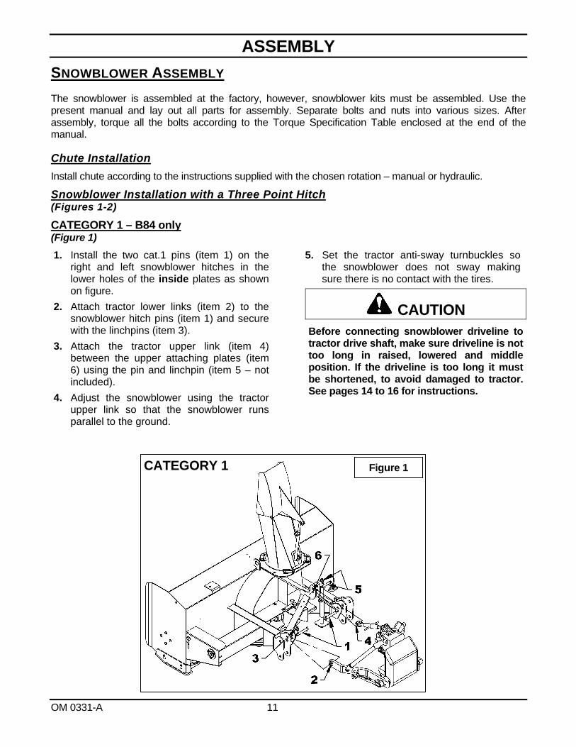
CATEGORY 1 – B84 only (Figure 1)
1. Install the two cat.1 pins (item 1) on the right and left snowblower hitches in the lower holes of the inside plates as shown on figure.
2. Attach tractor lower links (item 2) to the snowblower hitch pins (item 1) and secure with the linchpins (item 3).
3. Attach the tractor upper link (item 4) between the upper attaching plates (item 6) using the pin and linchpin (item 5 – not included).
4. Adjust the snowblower using the tractor upper link so that the snowblower runs parallel to the ground.
5. Set the tractor anti-sway turnbuckles so the snowblower does not sway making sure there is no contact with the tires.
CAUTION Before connecting snowblower driveline to tractor drive shaft, make sure driveline is not too long in raised, lowered and middle position. If the driveline is too long it must be shortened, to avoid damaged to tractor. See pages 14 to 16 for instructions.
CATEGORY 1 Figure 1
ASSEMBLY
OM 0331-A 12
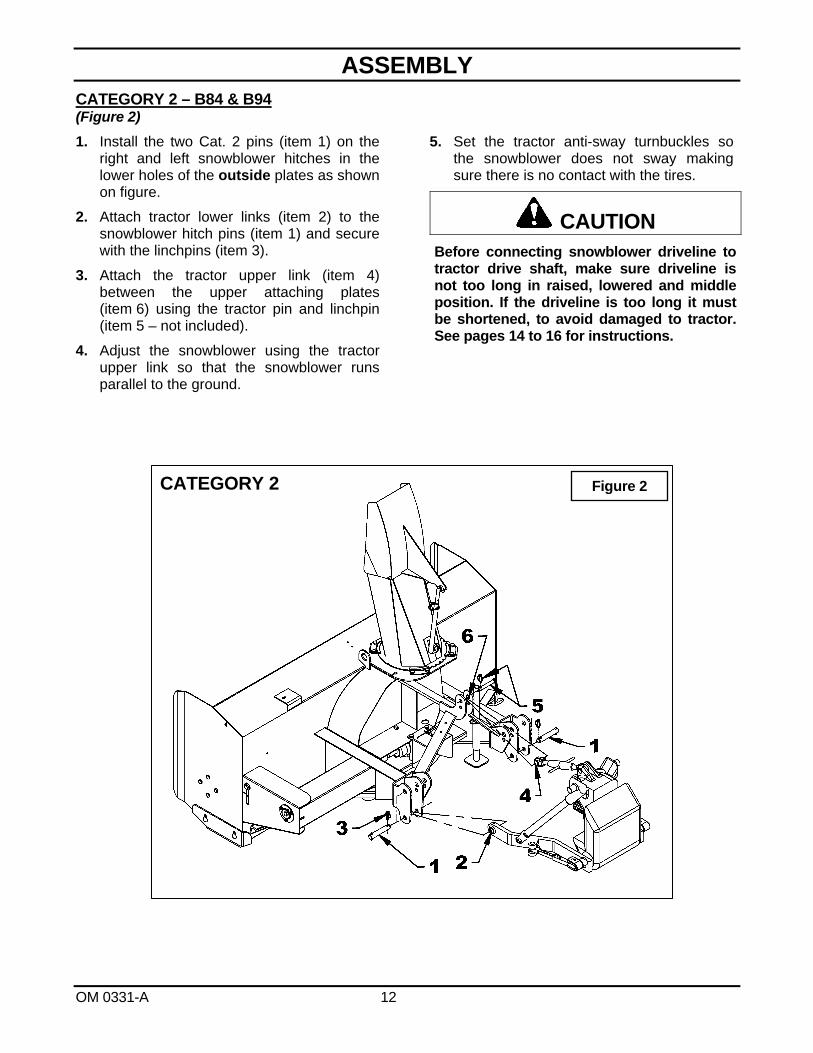
CATEGORY 2 – B84 & B94 (Figure 2)
1. Install the two Cat. 2 pins (item 1) on the right and left snowblower hitches in the lower holes of the outside plates as shown on figure.
2. Attach tractor lower links (item 2) to the snowblower hitch pins (item 1) and secure with the linchpins (item 3).
3. Attach the tractor upper link (item 4) between the upper attaching plates (item 6) using the tractor pin and linchpin (item 5 – not included).
4. Adjust the snowblower using the tractor upper link so that the snowblower runs parallel to the ground.
5. Set the tractor anti-sway turnbuckles so the snowblower does not sway making sure there is no contact with the tires.
CAUTION Before connecting snowblower driveline to tractor drive shaft, make sure driveline is not too long in raised, lowered and middle position. If the driveline is too long it must be shortened, to avoid damaged to tractor. See pages 14 to 16 for instructions.
Figure 2 CATEGORY 2
ASSEMBLY
OM 0331-A 13
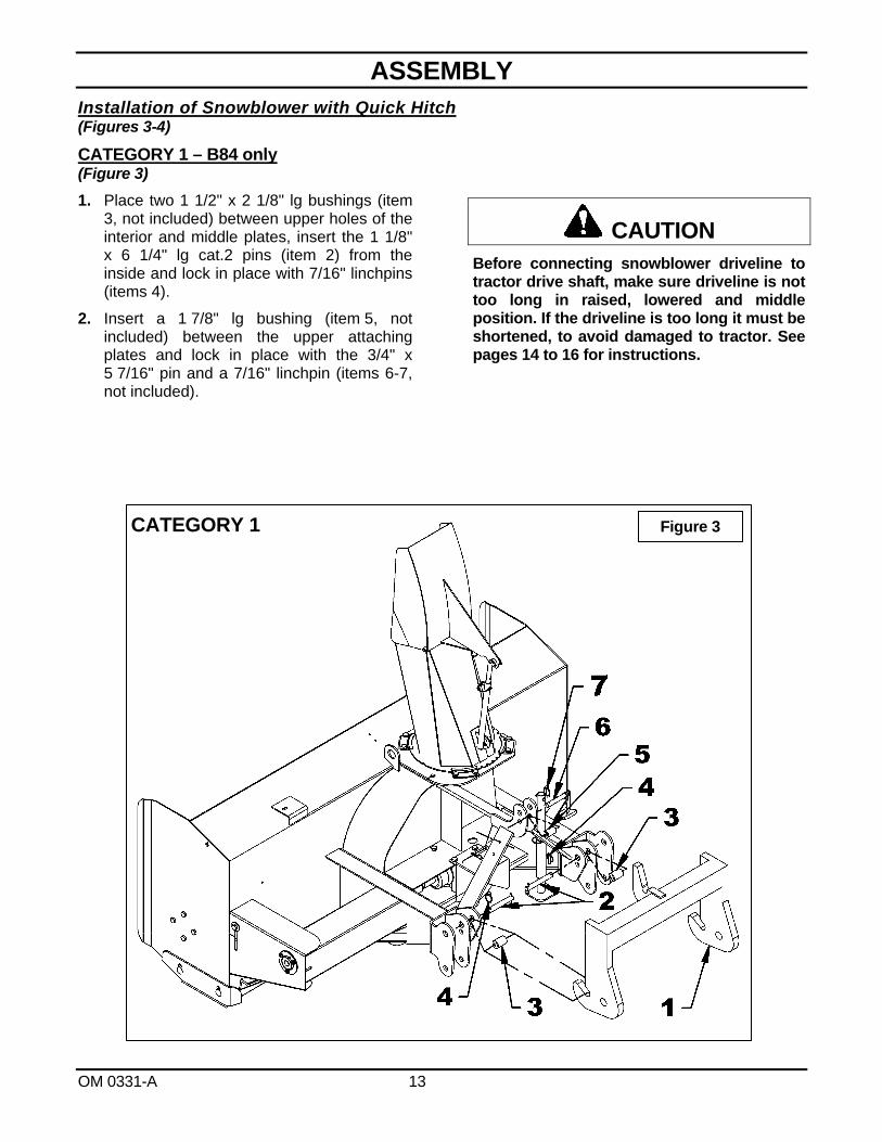
Installation of Snowblower with Quick Hitch (Figures 3-4)
CATEGORY 1 – B84 only (Figure 3)
1. Place two 1 1/2" x 2 1/8" lg bushings (item 3, not included) between upper holes of the interior and middle plates, insert the 1 1/8" x 6 1/4" lg cat.2 pins (item 2) from the inside and lock in place with 7/16" linchpins (items 4).
2. Insert a 1 7/8" lg bushing (item 5, not included) between the upper attaching plates and lock in place with the 3/4" x 5 7/16" pin and a 7/16" linchpin (items 6-7, not included).
Before connecting snowblower driveline to tractor drive shaft, make sure driveline is not too long in raised, lowered and middle position. If the driveline is too long it must be shortened, to avoid damaged to tractor. See pages 14 to 16 for instructions.
CAUTION
Figure 3 CATEGORY 1
ASSEMBLY
OM 0331-A 14
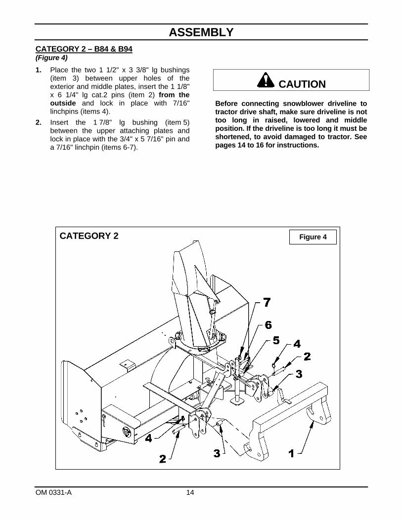
CATEGORY 2 – B84 & B94 (Figure 4)
1. Place the two 1 1/2" x 3 3/8" lg bushings (item 3) between upper holes of the exterior and middle plates, insert the 1 1/8" x 6 1/4" lg cat.2 pins (item 2) from the outside and lock in place with 7/16" linchpins (items 4).
2. Insert the 1 7/8" lg bushing (item 5) between the upper attaching plates and lock in place with the 3/4" x 5 7/16" pin and a 7/16" linchpin (items 6-7).
Before connecting snowblower driveline to tractor drive shaft, make sure driveline is not too long in raised, lowered and middle position. If the driveline is too long it must be shortened, to avoid damaged to tractor. See pages 14 to 16 for instructions.
CAUTION
CATEGORY 2 Figure 4
ASSEMBLY
OM 0331-A 15
IMPORTANT: A proper initial installation will give you years of satisfactory service on your equipment. Please read carefully following instructions that have been specially included to help you and ensure you are satisfied with your purchase. WARNING: Unfortunately, snowblowers will be faced with forgotten or hidden objects under the snow, such as : chain, tires, stones, pieces of wood, etc. In spite of all our efforts, machines are not built to resist all those conditions.
Danger: Tractors Too Big
It is dangerous to use a tractor that is too big and powerful. The tractor will always be able to overload the blower, even if the machine is already at maximum capacity. Furthermore, tractors being very high, the driveline angles will be excessive which means the universal joints will be very vulnerable and the life of the driveline will be dramatically reduced.
How to Determine Driveline Angles
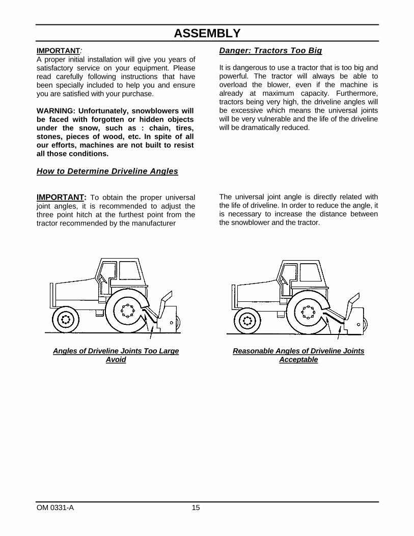
IMPORTANT: To obtain the proper universal joint angles, it is recommended to adjust the three point hitch at the furthest point from the tractor recommended by the manufacturer
The universal joint angle is directly related with the life of driveline. In order to reduce the angle, it is necessary to increase the distance between the snowblower and the tractor.
Angles of Driveline Joints Too Large Avoid
Reasonable Angles of Driveline Joints Acceptable

ASSEMBLY
OM 0331-A 16
Unequal Angles at Driveline Joints Avoid
Equal Angles at Driveline Joints Recommended
Angles at Each End of Driveline
A popular habit is to change the snowblower angle in order to obtain a better scraping effect. This practice can become harmful to the driveline since the angle at each end is unequal. This results in a fan speed variation as well as a drastic increase of load on cross and bearings. To be avoided: It is recommended to always keep tractor driveline and snowblower input shaft parallel.
Determining Driveline Length
IMPORTANT: Before using the equipment, make sure the driveline is not too long. At working position, the two half drivelines must intersect each other sufficiently to insure maximum efficiency but there must not be any interference.
1. To determine the "L" length for your tractor model first find the "X" factor by measuring the horizontal distance between the end of the tractor's drive shaft and the end of the snowblower's driven shaft when the snowblower is in transport position as shown on Figure 5.
2. Choose in the table below the "Y" factor according to the tractor category and deduct that number from "X" to determine "L" which is the center-to-center length between the universal joints.
L = X – Y
3 PTS HITCH
CATEGORY Y
Cat. 1 4 1/2"
Cat. 2 5 1/2"
Figure 5

ASSEMBLY
OM 0331-A 17
NOTE: Before cutting, make sure the two shafts intersect by at least 7 3/4" when in working position that is when the snowblower rests on the ground.
3. Hold the two half-shaft side by side and locate the "L" length between the two center-to-center half-shaft universal joints. Mark off the zone to be cut on both halves opposite each half-shaft guard as shown on Figure 6.
4. Cut off inner and outer guard tubes as well as the inner and outer telescopic sections.
5. Cut the guard a second time leaving the same distance between the end of the guard and the end of the shaft as existed before. To obtain the proper distance "A" shown on Figure 7, cut the guard according to the following table:
DISTANCE A Male PTO Female PTO
1 3/4" 1 1/4"
6. File down tubes and remove chips.
7. Apply grease to inside of outer telescopic section.
IMPORTANT: Work with fully guarded shafts only!
Figure 6
Figure 7
A
ASSEMBLY
OM 0331-A 18
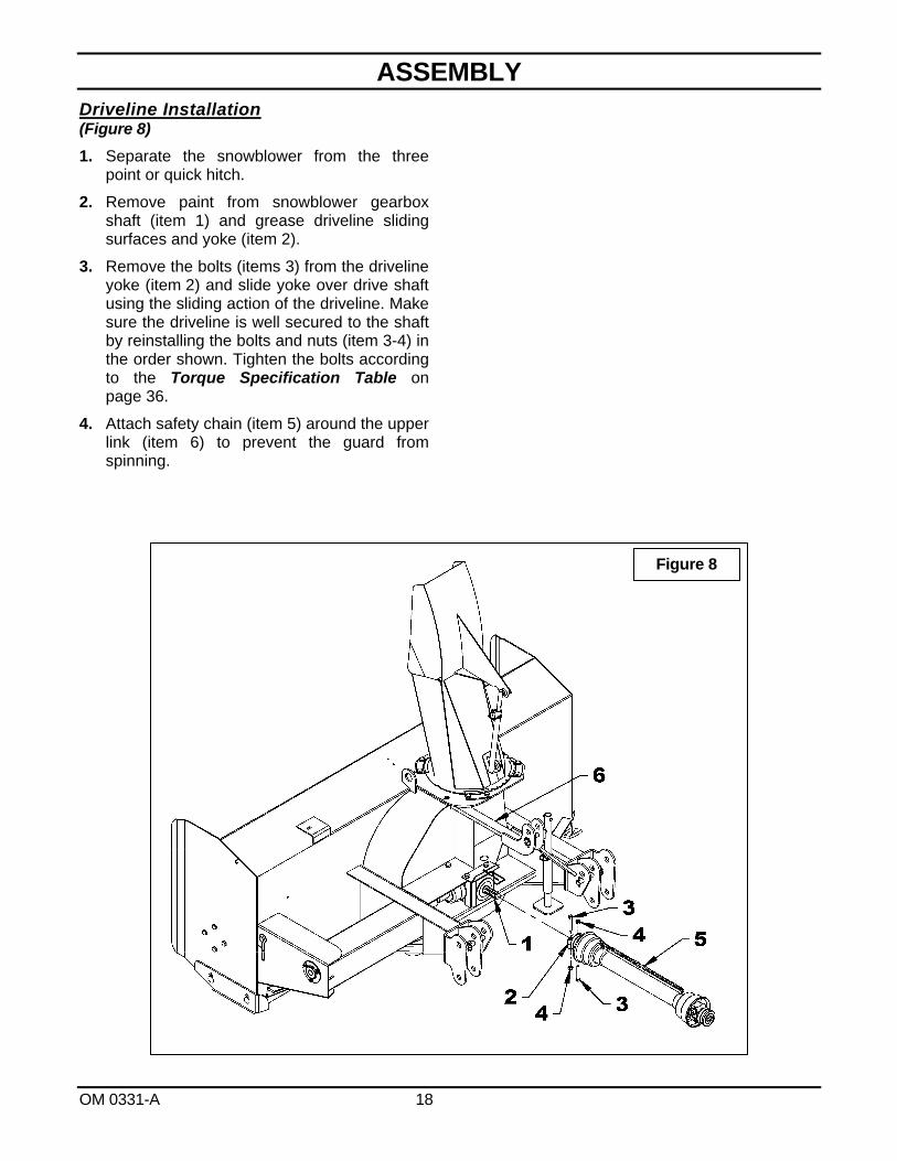
Driveline Installation (Figure 8)
1. Separate the snowblower from the three point or quick hitch.
2. Remove paint from snowblower gearbox shaft (item 1) and grease driveline sliding surfaces and yoke (item 2).
3. Remove the bolts (items 3) from the driveline yoke (item 2) and slide yoke over drive shaft using the sliding action of the driveline. Make sure the driveline is well secured to the shaft by reinstalling the bolts and nuts (item 3-4) in the order shown. Tighten the bolts according to the Torque Specification Table on page 36.
4. Attach safety chain (item 5) around the upper link (item 6) to prevent the guard from spinning.
Figure 8

ASSEMBLY
OM 0331-A 19
Figure 9
Figure 10
Removing Snowblower from Tractor (Figures 9-10-11)
Three Point Hitch
1. Set parking brake and turn engine off.
2. Figure 9: Remove the wire round lock pin (item 2), lower the parking stand (item 1) completely to the ground to release all pressure from the three-point and reinsert the wire round lock pin in the lower hole (item 3).
3. Figure 10: Detach upper link (item 4) by removing linchpin and pin (items 6-5).
4. Figure 10: Disconnect driveline from tractor and attach the driveline safety chain (item 7around the upper hitch (item 8).
5. Figure 10: Carefully detach lower links (items 2) from hitch pins (item 1) by removing linchpins (items 3), loosen anti-sway turnbuckles and slowly back tractor away from the snowblower.
IMPORTANT: To avoid damages to the snowblower, retorque all bolts after the first 10 hours of operation.
ASSEMBLY
OM 0331-A 20
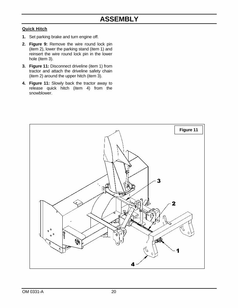
Quick Hitch
1. Set parking brake and turn engine off.
2. Figure 9: Remove the wire round lock pin (item 2), lower the parking stand (item 1) and reinsert the wire round lock pin in the lower hole (item 3).
3. Figure 11: Disconnect driveline (item 1) from tractor and attach the driveline safety chain (item 2) around the upper hitch (item 3).
4. Figure 11: Slowly back the tractor away to release quick hitch (item 4) from the snowblower.
Figure 11

OPERATION
OM 0331-A 21
GENERAL PREPARATION
1. Read the operator’s manual carefully before using the tractor and snowblower. Be thoroughly familiar with the controls and proper use of the equipment. Know how to stop the unit and disengage the controls quickly.
2. Make sure the snowblower is clear of snow before engaging the driveline.
3. Make sure the auger and fan operate freely.
4. Check the oil level in the worm Gearbox and if necessary, add 80W90 SAE gear oil, AGMA 5EP oil or equivalent.
5. Check the two shear bolts, one on the driving shaft, and the one on the PTO, for proper tightness.
6. Adjust so that the snowblower skid shoes run level.
7. Wear adequate winter outer garments while operating equipment.
OPERATING CONTROLS
Work and Travel Speed
Working ground speed will depend on the depth and density of the snow to be cleared. Normally, ground speed will range from 4 to 7 MPH for light, dry snowfalls 3 to 6 inches, and 1 to 3 MPH for heavy, wet or drifted snow. To transport, disengage the drive shaft and raise the snowblower to full transport height.
Raising and Lowering the Snowblower
Move the three point lever on right hand side of seat down or forward to lower, and up or rearward to raise.
WARNING To avoid personal injury, be sure the tractor engine is off, the drive shaft disengaged, and all movement has stopped before making any adjustments.
ADJUSTMENTS
Reduction Chain Tension Adjustment (Figure 12)
The premature wear of the chain may be caused by tension being too tight. It is therefore important not to tighten chain to its maximum. To adjust the tension on the drive chain, loosen the
bolt (item 1), securing the idler sprocket to the snowblower housing.
To tighten the chain, lower the bolt. Leave approximately 1/8" deflection in one span of the chain. Retighten securely the bolt holding the idler sprocket.
Skid Shoe Adjustment (Figure 12)
Adjust the skid shoes so that the snowblower runs level and according to the surface conditions so that stones are not thrown with the snow.
Adjust both skid shoes to the same height to keep the cutting edge level and adjust upwards for smooth surfaces.
Loosen skid shoe bolts (item 2) and adjust according to instructions below, and securely tighten bolts:
Clearance between cutting edge and surface: Paved surface: Insert bolts in lower hole. Uneven or gravel surface: Insert bolts according
to distance needed: 1/2" - middle hole 1" - upper hole
Manual Deflector Adjustment
Set the angle of deflection according to the distance the snow must be thrown. To set the deflector angle, remove the adjusting pipe hairpin and adjust the adjusting rod to the desired deflector angle. Secure with the adjusting pipe hairpin.
2
1
Figure 12

OPERATION
OM 0331-A 22
SNOW REMOVAL METHODS
When removing snow, do not use the snowblower as a dozer blade to push snow. Let the snowblower work its way through deep drifts. If the speed of your tractor is too fast, the snowblower may become overloaded and clog. For best results, raise the snowblower and remove a top layer of snow. A second pass with the snowblower will remove the remaining snow.
IMPORTANT: Use full RPM power when removing wet, sticky snow. Low RPM power will tend to clog the chute.
WARNING Do not use hands or feet to unclog chute. Do not attempt to clear clogged chute of snow while tractor engine is running. If the chute clogs, disengage the drive shaft, shut off the tractor engine, remove the ignition key, wait for all movement to stop, and then clear the snow from the chute.
A definite pattern of operation is required to thoroughly clean the snow area. These patterns will avoid throwing snow in unwanted places as well as eliminating a second removal of snow
Where it is possible to throw the snow to the left and right (above), as on a long driveway, it is advantageous to start in the middle. Plow from one end to the other, throwing snow to both sides without changing the direction of the discharge guide.
If the snow can only be thrown to one side of the driveway or sidewalk (above), start on the opposite side. At the end of the first pass, rotate the discharge guide 180 degrees for the return pass. At the end of each succeeding pass, rotate the discharge guide 180 degrees to maintain direction of throw in the same area.

MAINTENANCE
OM 0331-A 23
MAINTENANCE
Shearbolts
Check the shearbolts indicated on the figure below at frequent intervals for proper tightness to be sure the blower is in safe working condition. If the shearbolts need replacement, use the following parts only:
Drive shaft:
Shearbolt hex. 5/16" NC x 1 3/4" gr.5 with nut. Part # 665547.
Driveline:
B84 Shearbolt M10 x 1.5 x 55mm gr. 8.8 with nut. Part # 657199 B94 Shearbolt M10 x 1.5 x 55mm gr. 8.8 with nut. Part # 657199.
WARNING Provide adequate blocking before working under the snowblower when in the raised position. Driveline
IMPORTANT: When the snowblower is not used for more than two weeks, perform driveline maintenance and always store it in a dry place, away from bad weather conditions.
MAINTENANCE
OM 0331-A 24
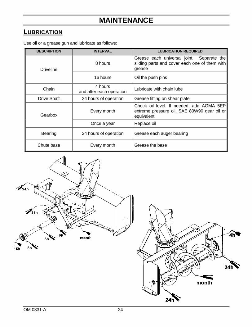
LUBRICATION
Use oil or a grease gun and lubricate as follows:
DESCRIPTION INTERVAL LUBRICATION REQUIRED
Driveline 8 hours
Grease each universal joint. Separate the sliding parts and cover each one of them with grease
16 hours Oil the push pins
Chain 4 hours
and after each operation Lubricate with chain lube
Drive Shaft 24 hours of operation Grease fitting on shear plate
Gearbox Every month
Check oil level. If needed, add AGMA 5EP extreme pressure oil, SAE 80W90 gear oil or equivalent.
Once a year Replace oil
Bearing 24 hours of operation Grease each auger bearing
Chute base Every month Grease the base

MAINTENANCE
OM 0331-A 25
DRIVELINE TROUBLESHOOTING AVOIDABLE DAMAGES POSSIBLE CAUSES CORRECTIVE ACTIONS
QUICK-DISCONNECT YOKE
Quick-disconnect pin tight or completely seized.
Quick-disconnect pin damaged (broken or bent)
Quick-disconnect pin damaged in the locking portion.
Quick-disconnect pin dirty (insufficient maintenance).
Quick-disconnect pin defective (forced engagement, incorrect handling)
Excessive shaft length.
Axial loads too high.
Clean, oil and follow service instructions.
Replace quick-disconnect pin.
Shorten shaft length (cut both telescopic tubes as well as shield and remove burrs).
Replace quick-disconnect pin.
Clean and grease telescopic tubes, and replace both tubes, if necessary.
Replace quick-disconnect pin.
Note: Quick-disconnect pins must be cleaned and greased every 16 hours.
AVOIDABLE DAMAGES POSSIBLE CAUSES CORRECTIVE ACTIONS
YOKE Yoke ears deformation
Excessive shaft length.
Axial loads too high.
Excessive working angle and torque.
Shorten shaft length (cut both telescopic tubes as well as shields and remove burrs).
Replace defective yokes.
Clean and grease telescopic tubes, and replace both tubes, if necessary.
Replace defective yokes.
Verify compatibility between shaft and working conditions (torque vs. angle).
Disengage tractor driveline during cornering or when lifting or lowering the implement.
Change to a larger driveline size.
Replace defective yokes.
Yoke ears distorted.
Overload caused by high starting and peak torques.
Engage driveline more carefully.
Use appropriate safety devices.
Replace defective yokes.
Yoke ears worn or pounded.
Excessive working angle. Avoid excessive working angle.
Disengage tractor driveline during cornering.
Replace defective yokes.
MAINTENANCE
OM 0331-A 26
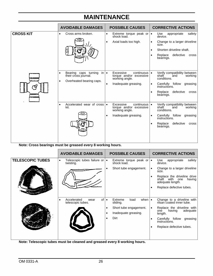
AVOIDABLE DAMAGES POSSIBLE CAUSES CORRECTIVE ACTIONS
CROSS KIT Cross arms broken.
Extreme torque peak or shock load.
Axial loads too high.
Use appropriate safety device.
Change to a larger driveline size.
Shorten driveline shaft.
Replace defective cross bearings.
Bearing caps turning in their cross journal.
Overheated bearing caps.
Excessive continuous torque and/or excessive working angle.
Inadequate greasing.
Verify compatibility between shaft and working conditions.
Carefully follow greasing instructions.
Replace defective cross bearings.
Accelerated wear of cross kit.
Excessive continuous torque and/or excessive working angle.
Inadequate greasing.
Verify compatibility between shaft and working conditions.
Carefully follow greasing instructions.
Replace defective cross bearings.
Note: Cross bearings must be greased every 8 working hours.
AVOIDABLE DAMAGES POSSIBLE CAUSES CORRECTIVE ACTIONS
TELESCOPIC TUBES
Telescopic tubes failure or twisting.
Extreme torque peak or shock load.
Short tube engagement.
Use appropriate safety device.
Change to a larger driveline size.
Replace the driveline drive shaft with one having adequate length.
Replace defective tubes.
Accelerated wear of telescopic tubes.
Extreme load when sliding.
Short tube engagement.
Inadequate greasing.
Dirt
Change to a driveline with rilsan coated inner tube.
Replace the driveline with one having adequate length.
Carefully follow greasing instructions.
Replace defective tubes.
Note: Telescopic tubes must be cleaned and greased every 8 working hours.
MAINTENANCE
OM 0331-A 27
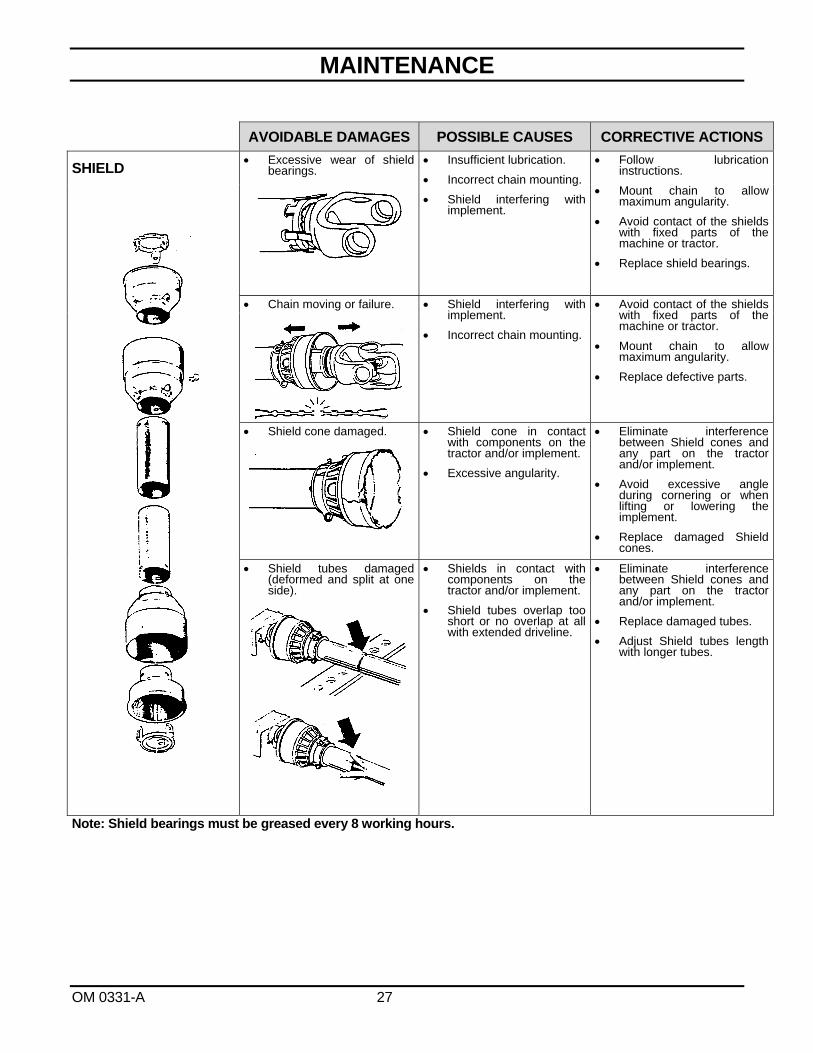
Note: Shield bearings must be greased every 8 working hours.
AVOIDABLE DAMAGES POSSIBLE CAUSES CORRECTIVE ACTIONS
SHIELD Excessive wear of shield
bearings.
Insufficient lubrication.
Incorrect chain mounting.
Shield interfering with implement.
Follow lubrication instructions.
Mount chain to allow maximum angularity.
Avoid contact of the shields with fixed parts of the machine or tractor.
Replace shield bearings.
Chain moving or failure. Shield interfering with implement.
Incorrect chain mounting.
Avoid contact of the shields with fixed parts of the machine or tractor.
Mount chain to allow maximum angularity.
Replace defective parts.
Shield cone damaged.
Shield cone in contact with components on the tractor and/or implement.
Excessive angularity.
Eliminate interference between Shield cones and any part on the tractor and/or implement.
Avoid excessive angle during cornering or when lifting or lowering the implement.
Replace damaged Shield cones.
Shield tubes damaged (deformed and split at one side).
Shields in contact with components on the tractor and/or implement.
Shield tubes overlap too short or no overlap at all with extended driveline.
Eliminate interference between Shield cones and any part on the tractor and/or implement.
Replace damaged tubes.
Adjust Shield tubes length with longer tubes.
PARTS
OM 0331-A 28
INTRODUCTION
All parts are illustrated in "exploded views" which show the individual parts in their normal relationship to each other. Reference numbers are used in the illustrations. These numbers correspond to those in the "Reference Number" (REF) column, and are followed by the description and quantity required.
O/L - "Obtain Locally" in the part number column indicates common hardware that is available at your local hardware supply.
Right hand and left hand are determined by those seen by the conductor standing behind the equipment.
Orders must give the complete description, correct part number, the total amount required, the serial number, the method of shipment and the shipping address.
The manufacturer reserves the rights to change, modify, or eliminate from time to time, for technical or other reasons, certain or all data, specifications, or the product or products themselves, without any liability or obligation.
The parts listed here are available through your local dealer.
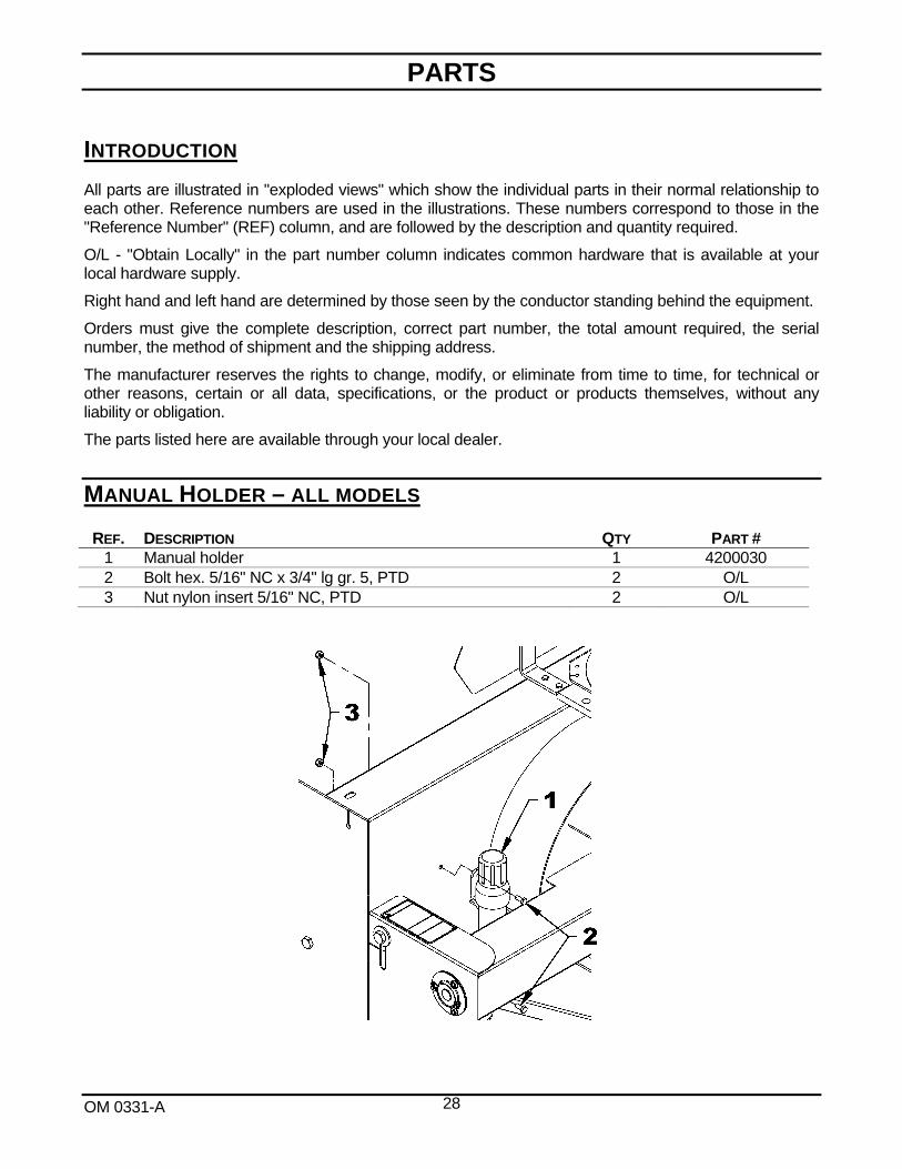
MANUAL HOLDER – ALL MODELS
REF. DESCRIPTION QTY PART # 1 Manual holder 1 4200030 2 Bolt hex. 5/16" NC x 3/4" lg gr. 5, PTD 2 O/L 3 Nut nylon insert 5/16" NC, PTD 2 O/L
PARTS
OM 0331-A 29
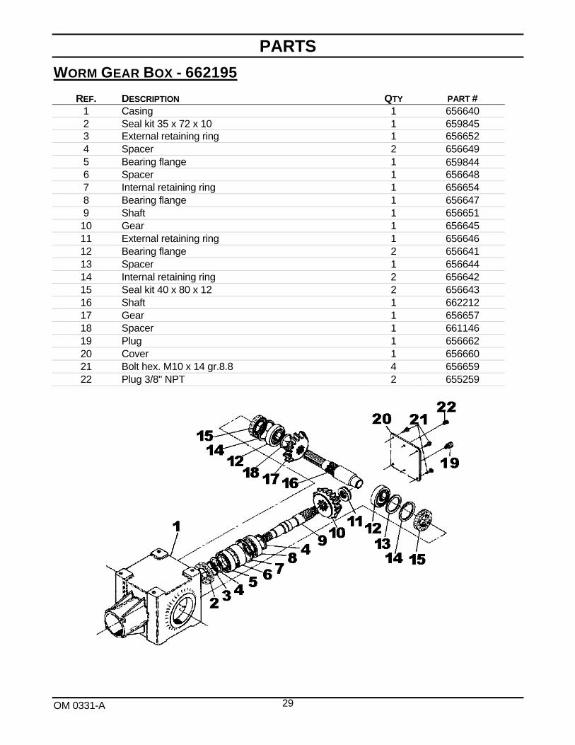
WORM GEAR BOX - 662195
REF. DESCRIPTION QTY PART # 1 Casing 1 656640 2 Seal kit 35 x 72 x 10 1 659845 3 External retaining ring 1 656652 4 Spacer 2 656649 5 Bearing flange 1 659844 6 Spacer 1 656648 7 Internal retaining ring 1 656654 8 Bearing flange 1 656647 9 Shaft 1 656651 10 Gear 1 656645 11 External retaining ring 1 656646 12 Bearing flange 2 656641 13 Spacer 1 656644 14 Internal retaining ring 2 656642 15 Seal kit 40 x 80 x 12 2 656643 16 Shaft 1 662212 17 Gear 1 656657 18 Spacer 1 661146 19 Plug 1 656662 20 Cover 1 656660 21 Bolt hex. M10 x 14 gr.8.8 4 656659 22 Plug 3/8" NPT 2 655259
PARTS
OM 0331-A 30
SNOWBLOWERS –B84 & B94

PARTS
OM 0331-A 31
SNOWBLOWERS –B84 & B94
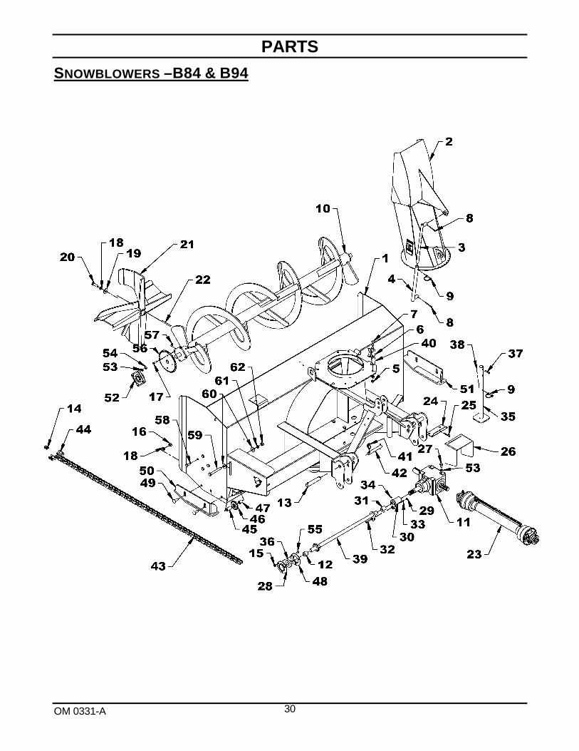
REF. DESCRIPTION QTY PART # 1 Housing 1 --- 2 Chute assembly (including adjustment tube and rod) 1 668101 3 Adjustment rod 1 654074 4 Adjustment tube 1 654076 5 Serrated flange nut 1/2" NC PTD 8 O/L 6 Retaining plate 4 654197 7 Bolt hex. 1/2" NC x 1 1/4" gr.5 PTD 8 O/L 8 Cotter pin Ø1/4" x 2" PTD 4 O/L 9 Round wire lock pin 1/4" x 2" PTD 2 1900006 10 Auger – B84 1 666278 Auger – B94 1 666290
11 Gearbox 1 662195 12 Spacer ring 0 3/32" 1 667015 13 Hitch pin 1 1/8" x 6 1/4" lg Cat. 2 2 4600042 14 Half link #60 1 654025 15 Serrated flange nut 3/8" NC PTD 3 O/L 16 Nut hex. 5/8" NC PTD 4 O/L 17 Bolt hex. 3/8" NC x 1 1/2" gr.5 PTD 4 O/L 18 Lockwasher 5/8" PTD 5 O/L 19 Flat washer 5/8" PTD 1 O/L 20 Bolt hex. 5/8" NC x 2" gr.5 PTD 1 O/L 21 Fan 1 668967 22 Key 3/8" x 3/8" x 4" lg 1 4500075 23 Driveline Series 50 1 662194 Driveline Series 60 1 662538
24 Driveline shield bracket 1 668449 25 Hairpin 3mm x 65mm lg PTD 1 1800004 26 Driveline shield 1 668057 27 Bolt hex. 1/2" NC x 1" gr.5 PTD 8 O/L 28 Flange, 3 holes with grease fitting and groove 1 4300015 29 Nut hex. 5/16" NC PTD 1 O/L 30 Shear plate 1 666257 31 Oilite bushing 1 4300056 32 Shearbolt 5/16"NC x 1 3/4" gr.5, incl. nut 1 665547 33 Lockwasher 5/16" PTD 1 O/L 34 Grease fitting 1/4" NF 1 654106 35 Parking stand 1 668091 36 Bearing 1 1/8" with setscrew and grease system 1 4300040 37 Bolt hex. 1/4" NC x 1 1/4" gr. 5 PTD 1 O/L 38 Nylon insert hex. nut 1/4" NC PTD 1 O/L 39 Driving shaft – B84 1 668046 Driving shaft – B94 1 668476
40 Spacer 4 668549

PARTS
OM 0331-A 32
SNOWBLOWERS –B84 & B94
REF. DESCRIPTION QTY PART # 41 Linchpin 7/16" PTD 2 1900003 42 Hitch pin Cat. 1 2 4600043 43 Chain #60 x 90 links 1 662447 44 Connecting link #60 1 654839 45 Spacer ring 1 3/4" lg 1 668093 46 Idler sprocket 60A12 1 3300022 47 Spacer ring .656"ID x 1.51 lg x 1" ext. 1 667777 48 Flange, 3 holes with grease groove 1 4300014 49 Bolt carriage 1/2" NC x 1" lg gr.5 PTD 4 0300022 50 Left adjustable skid shoe 1 666287 51 Right adjustable skid shoe 1 666288 52 Flange bearing 1 1/4" hole, 4 holes 2 4300001 53 Lockwasher 1/2" PTD 16 1200006 54 Nut hex. 1/2" NC PTD 8 0900006 55 Bolt carriage 3/8" NC x 3/4" lg PTD 3 0300007 56 Sprocket 60A32 1 654167 57 Nylon insert nut 3/8" NC gr.5 PTD 4 O/L 58 Bolt hex. 1/2" NC x 1 1/2" lg gr.5 PTD 8 O/L 59 Bolt hex. 5/8" NC x 5" lg gr.5 PTD 1 O/L 60 Flat washer 5/8" (11/16" dia. hole) 2 O/L 61 Lockwasher 5/8" PTD 1 O/L 62 Nut hex. 5/8" NC gr.5 PTD 1 O/L

PARTS
OM 0331-A 33
DRIVELINE 662194 FOR B84
REF. DESCRIPTION QTY. PART #
1 Push pin yoke assembly 1 657209 2 Journal cross 2 657200
3 Outer yoke 1 663119 4 Outer tube 1 663123 5 Inner tube 1 663124 6 Inner yoke 1 663126 7 Yoke and hub assembly 1 662198 8 Bolt and nut 2 662199 9 Grease fitting 1 663129 10 Ball Ø14" 23 663163 11 Shear bolt M10 x 1.5 x 55mm gr. 8.8 PTD and nut 1 657199 12 Shields with safety chain 1 657221 13 Pin for male tube 1 663125 14 Pin for female tube 1 663120

PARTS
OM 0331-A 34
DRIVELINE – 662538 FOR B94
Ref. Description Qty Part # 1 Slide collar yoke assembly 1 4700083 2 Universal joint kit 2 663134 3 Outer yoke 1 663136 4 Outer tube 1 663140 5 Inner tube 1 663142 6 Inner yoke 1 663144 7 Yoke and hub assembly 1 663145 8 Bolt and nut 2 662199 9 Grease fitting 1 663148 10 Ball 24 663162 11 Shear bolt and nut, M10 x 1.5 x 55 mm gr. 8.8 PTD 1 657199 12 Shields with safety chain 1 663150 13 Outer circlip 1 4700084 14 Sliding sleeve collar 1 4700085 15 Spring 1 4700086 16 Fixed sleeve 1 4700087 17 Ball 1/2" 3 4700088 18 Roll pin for outer tube 1 663153 19 Roll pin for inner tube 1 663157

AVAILABLE OPTIONS
OM 0331-A 35
MANUAL CHUTE ROTATION
HYDRAULIC CHUTE ROTATION
ELECTRIC CHUTE ROTATION
ELECTRIC CHUTE DEFLECTOR

WARRANTY
OM 0331-A 36
RADTECH warrants to the original buyer that the equipment is free from defects in material and workmanship. RADTECH's obligation, under this warranty, will be limited to the repair or replacement of any non-wear part or component, which RADTECH finds to be defective within one year from the date of original purchase (unless otherwise-specified). The applicable warranty period for commercial or rental use shall be ninety (90) days from the date of purchase
In no event shall RADTECH be liable for consequential, special, direct or indirect damages incurred by the buyer/user.
All components not manufactured by RADTECH (such as motors, actuators, hydraulic components, tires, ...etc.) are covered by the original manufacturer's warranty in conjunction with RADTECH
RADTECH's obligation under this warranty shall be limited to repairing or replacing, free of charge to the original purchaser, any part that, in RADTECH's judgment, shall show evidence of such defect, provided the distributor returns the part prepaid within thirty (30) days from date of failure.
This warranty shall not be interpreted to render RADTECH liable for injuries or damages of any kind or nature to person or property. This warranty does not extend to losses because of delays, or to any expenses or losses incurred for labor, substitute machinery, rental or for any other reason.
Except as set forth above, RADTECH shall have no obligation or liability of any kind on account of any of its equipment and shall not be liable for special or consequential damages. RADTECH makes no other warranty, expressed or implied, and specifically, RADTECH disclaims any implied warranty or merchantability or fitness for a particular purpose. Some states or provinces do not permit limitations or exclusions of implied warranties or incidental or consequential damages, so the limitations or exclusions in this warranty may not apply.
This warranty is subject to any existing conditions of supply, which may directly affect our ability to obtain materials or manufacture replacement parts. RADTECH reserves the right to make improvements in design or changes in specifications at any time, without incurring any obligation to owners of units previously sold.
No one is authorized to alter, modify or enlarge this warranty nor the exclusions, limitations and reservations.
2835 Chemin de l'Aéroport, Thetford Mines (Québec) G6G 5R7
Tel.: (418) 338-4499 Fax: (418) 388-6090 Internet : www.radinter.com e-mail : [email protected]
TORQUE SPECIFICATION TABLE
OM 0331-A 37
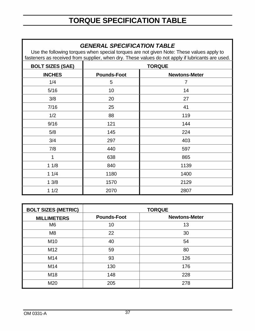
GENERAL SPECIFICATION TABLE Use the following torques when special torques are not given Note: These values apply to
fasteners as received from supplier, when dry. These values do not apply if lubricants are used.
BOLT SIZES (SAE) TORQUE
INCHES Pounds-Foot Newtons-Meter
1/4 5 7
5/16 10 14
3/8 20 27
7/16 25 41
1/2 88 119
9/16 121 144
5/8 145 224
3/4 297 403
7/8 440 597
1 638 865
1 1/8 840 1139
1 1/4 1180 1400
1 3/8 1570 2129
1 1/2 2070 2807
BOLT SIZES (METRIC) TORQUE
MILLIMETERS Pounds-Foot Newtons-Meter
M6 10 13
M8 22 30
M10 40 54
M12 59 80
M14 93 126
M14 130 176
M18 148 228
M20 205 278

Manufactured by:
2835, Chemin de l’Aéroport Thetford Mines, Québec, Canada, G6G 5R7 Tel.: (418) 338-4499 - Fax: (418) 338-6090 e-mail : [email protected] Internet : www.radinter.com Printed in Canada