operator manual - w900, t660, t800, c500, 963 (y53-1203 ......introduction vehiclesafety warning!...
TRANSCRIPT


Contents
Safety
Emergency
Controls
Driving
Maintenance
Information
Index
1
2
3
4
5
6
7
Contents
©2017 PACCAR Inc - All Rights Reserved
This manual illustrates and describes the operation of features or equipment which may be either standard or optional onthis vehicle. This manual may also include a description of features and equipment which are no longer available or werenot ordered on this vehicle. Please disregard any illustrations or descriptions relating to features or equipment which arenot on this vehicle.
PACCAR reserves the right to discontinue, change specifications, or change the design of its vehicles at any time, withoutnotice and without incurring any obligation.
The information contained in this manual is proprietary to PACCAR. Reproduction, in whole or in part, by any means is strictlyprohibited without prior written authorization from PACCAR Inc.
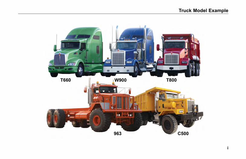
Truck Model Example
i

SAFETY
INTRODUCTIONAbout this Manual. . . . . . . . . . . . . . . . 1-3Safety Alerts . . . . . . . . . . . . . . . . . . 1-3Vehicle Safety . . . . . . . . . . . . . . . . . 1-5Environmental Protection . . . . . . . . . . . . 1-6Data Recorder . . . . . . . . . . . . . . . . . 1-7Repairs . . . . . . . . . . . . . . . . . . . . 1-7Greenhouse Gas Certification . . . . . . . . . . 1-8Additional Sources of Information . . . . . . . . . 1-9
CAB AND FRAME ACCESSSafety . . . . . . . . . . . . . . . . . . . . 1-10Door Lock and Keys . . . . . . . . . . . . . 1-14Remote Keyless Entry (Option) . . . . . . . . . 1-14
GETTING TO YOUR ENGINEHood Hold Downs. . . . . . . . . . . . . . . 1-17Hood Tilt . . . . . . . . . . . . . . . . . . 1-17Hood Lock . . . . . . . . . . . . . . . . . . 1-18
(03/17) Y53-1203-1E1 1-1
1
SAFETY
Hood Safety Cable . . . . . . . . . . . . . . 1-19
SEATS AND RESTRAINTSIntroduction . . . . . . . . . . . . . . . . . 1-20Safety Restraint Belts . . . . . . . . . . . . . 1-21Tether Belts . . . . . . . . . . . . . . . . . 1-25Komfort-Latch® Feature . . . . . . . . . . . . 1-26During Pregnancy. . . . . . . . . . . . . . . 1-27Belt Damage and Repair . . . . . . . . . . . . 1-28Safety Restraint Tips . . . . . . . . . . . . . 1-28Sleeper Bunks and Restraints . . . . . . . . . 1-29
START-UPIntroduction . . . . . . . . . . . . . . . . . 1-33Safe Vehicle Operation . . . . . . . . . . . . 1-33Vehicle Loading. . . . . . . . . . . . . . . . 1-34Emergency Equipment . . . . . . . . . . . . 1-35Driver's Check List . . . . . . . . . . . . . . 1-35
1-2 Y53-1203-1E1 (03/17)
1

INTRODUCTION
INTRODUCTION
About this Manual
Congratulations! Your selection of aKenworth truck was a wise investment.Kenworth trucks are recognized asthe industry standard for quality andreliability.
Please take the time to get acquaintedwith your vehicle by reading thisOperator’s Manual. We recommendthat you read and understand thismanual from beginning to end beforeyou operate your truck. This manualexplains the safe, efficient operationand maintenance of your Kenworth.
NOTEAfter you’ve read this manual, itshould be stored in the cab for con-venient reference and remain withthis truck when sold.
Your Kenworth may not have all thefeatures or options mentioned in thismanual. Therefore, you should paycareful attention to the instructions thatpertain to just your vehicle. In addition,if your vehicle is equipped with specialequipment or options not discussed inthis manual, consult your dealer or themanufacturer of the equipment.
All information contained in thismanual is based on the latestproduction information available at thetime of publication. Kenworth TruckCompany reserves the right to makechanges at any time without notice.
Safety Alerts
Please read and follow all of thesafety alerts contained in this manual.They are there for your protectionand information. These alerts canhelp you avoid injury to yourself, yourpassengers, and help prevent costlydamage to the vehicle. Safety alertsare highlighted by safety alert symbolsand signal words such as "WARNING","CAUTION", or "NOTE". Please do notignore any of these alerts.
(03/17) Y53-1203-1E1 1-3
1
INTRODUCTION
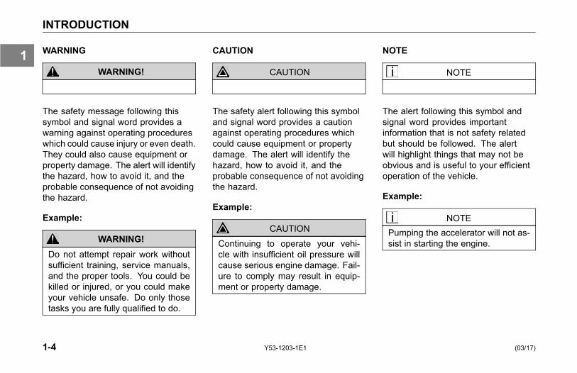
WARNING
WARNING!
The safety message following thissymbol and signal word provides awarning against operating procedureswhich could cause injury or even death.They could also cause equipment orproperty damage. The alert will identifythe hazard, how to avoid it, and theprobable consequence of not avoidingthe hazard.
Example:
WARNING!Do not attempt repair work withoutsufficient training, service manuals,and the proper tools. You could bekilled or injured, or you could makeyour vehicle unsafe. Do only thosetasks you are fully qualified to do.
CAUTION
CAUTION
The safety alert following this symboland signal word provides a cautionagainst operating procedures whichcould cause equipment or propertydamage. The alert will identify thehazard, how to avoid it, and theprobable consequence of not avoidingthe hazard.
Example:
CAUTIONContinuing to operate your vehi-cle with insufficient oil pressure willcause serious engine damage. Fail-ure to comply may result in equip-ment or property damage.
NOTE
NOTE
The alert following this symbol andsignal word provides importantinformation that is not safety relatedbut should be followed. The alertwill highlight things that may not beobvious and is useful to your efficientoperation of the vehicle.
Example:
NOTEPumping the accelerator will not as-sist in starting the engine.
1-4 Y53-1203-1E1 (03/17)
1

INTRODUCTION
Vehicle Safety
WARNING!Do not drive after drinking alcohol orusing other substances that may af-fect the senses, including prescrip-tion medications. Your reflexes, per-ceptions, and judgment can be af-fected by even a small amount of al-cohol or other substances, and cancause a serious or even fatal acci-dent. Failure to comply may result indeath, personal injury, or equipmentand property damage.
WARNING!Do not text while driving. Your re-flexes, perceptions, and judgmentcan be affected while texting orusing any other form of mobile mes-saging while driving. Failure to com-ply may result in death, personalinjury, or equipment and propertydamage.
Make sure your Kenworth is in topworking condition before headingout on the road, it is the responsibledriver's duty to do so. Inspect thevehicle according to the Driver's CheckList beginning on page 1-35.
Every new Kenworth vehicle isdesigned to conform to all FederalMotor Vehicle Safety Standardsapplicable at the time of manufacture.Even with these safety features,continued safe and reliable operationdepends greatly upon regular vehiclemaintenance. Follow the maintenancerecommendations found in PreventiveMaintenance on page 5-7. This willhelp preserve your investment.
Keep in mind that even a wellmaintained vehicle must be operatedwithin the range of its mechanicalcapabilities and the limits of its loadratings. See the Tire, Rim and Weight
Ratings Data Label on the driver's dooredge.
Safe driving is only possible with theproper concentration on the drivingtask. Keep distraction to a minimum toimprove your concentration. Examplesof distractions may include radiocontrols, GPS navigation controls,cellular telephone calls, cellular textmessages, reading or reaching forsomething on the floor. Minimizingyour distractions will improve safedriving and will help avoid an accidentinvolving death or personal injury.
Be aware of local regulations that mayprohibit the use of cellular telephoneswhile driving. In addition to being anunsafe practice, it may be against localor federal ordinances to use cellulardevices while operating the vehicle.
This manual is not a training manual.It cannot tell you everything you needto know about driving your Kenworth
(03/17) Y53-1203-1E1 1-5
1
INTRODUCTION
vehicle. For that you need a goodtraining program or truck drivingschool. If you have not been trained,get the proper training before youdrive. Only qualified drivers shoulddrive this vehicle.
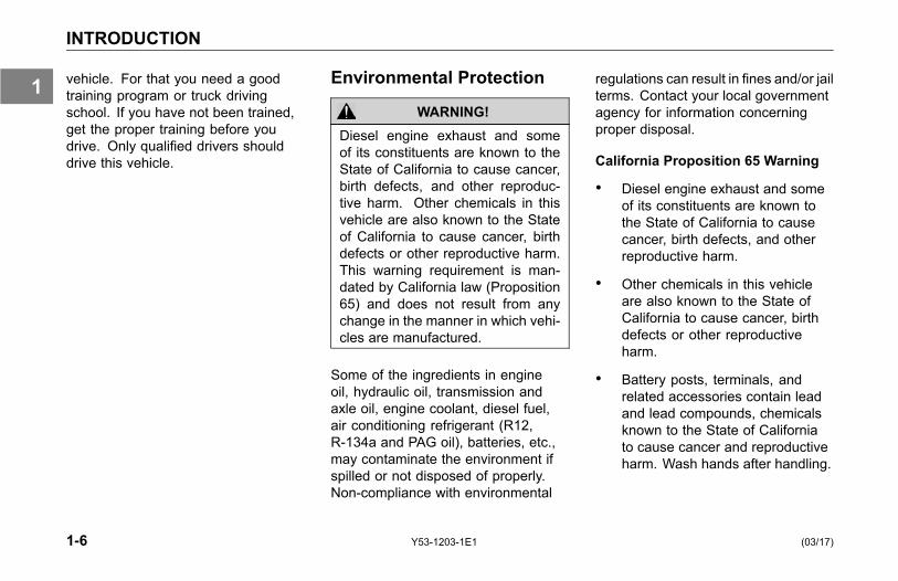
Environmental Protection
WARNING!Diesel engine exhaust and someof its constituents are known to theState of California to cause cancer,birth defects, and other reproduc-tive harm. Other chemicals in thisvehicle are also known to the Stateof California to cause cancer, birthdefects or other reproductive harm.This warning requirement is man-dated by California law (Proposition65) and does not result from anychange in the manner in which vehi-cles are manufactured.
Some of the ingredients in engineoil, hydraulic oil, transmission andaxle oil, engine coolant, diesel fuel,air conditioning refrigerant (R12,R-134a and PAG oil), batteries, etc.,may contaminate the environment ifspilled or not disposed of properly.Non-compliance with environmental
regulations can result in fines and/or jailterms. Contact your local governmentagency for information concerningproper disposal.
California Proposition 65 Warning
• Diesel engine exhaust and someof its constituents are known tothe State of California to causecancer, birth defects, and otherreproductive harm.
• Other chemicals in this vehicleare also known to the State ofCalifornia to cause cancer, birthdefects or other reproductiveharm.
• Battery posts, terminals, andrelated accessories contain leadand lead compounds, chemicalsknown to the State of Californiato cause cancer and reproductiveharm. Wash hands after handling.
1-6 Y53-1203-1E1 (03/17)
1
INTRODUCTION
Data Recorder
California Vehicle Code - Section9951- Disclosure of Recording Device
Your vehicle may be equipped with oneor more recording devices commonlyreferred to as "event data recorders(EDR)" or "sensing and diagnosticmodules (SDM)". If you are involved inan accident, the device(s) may havethe ability to record vehicle data thatoccurred just prior to and/or during theaccident. For additional information onyour rights associated with the use ofthis data, contact
• the California Department of MotorVehicles - Licensing OperationsDivision– or –
• www.dmv.ca.gov
Repairs
WARNING!Do not attempt repair work withoutsufficient training, service manuals,and the proper tools. You couldmake your vehicle unsafe. Do onlythose tasks you are fully qualified todo. Failure to comply may result inpersonal injury, death, or equipmentand property damage.
WARNING!Modifying your vehicle can makeit unsafe. Some modifications canaffect your vehicle's electrical sys-tem, stability, or other importantfunctions. Before modifying yourvehicle, check with your dealer tomake sure it can be done safely.Improper modifications may result indeath, personal injury, or equipmentand property damage.
Your dealer’s service center is the bestplace to have your vehicle repaired.You can find dealers all over thecountry with the equipment and trainedpersonnel to get you back on the roadquickly—and keep you there.
Your vehicle is a complex machine.Anyone attempting repairs on it needsgood mechanical training and theproper tools. However, all warrantyrepairs must be performed by anauthorized service facility. If you aren’tan experienced mechanic, or don’thave the right equipment, pleaseleave all repairs to an authorizedservice facility. They are the onesbest equipped to do the job safely andcorrectly.
To find a dealer near you, give us acall toll-FREE at 1-800-KW-ASSIST(1-800-592-7747) 24-7-365 daysa year or visit us online atwww.kenworth.com and click on
(03/17) Y53-1203-1E1 1-7
1

INTRODUCTION
the "dealers" link. When it comestime for service work, your KenworthDealer will need your VehicleIdentification Number (VIN), seeVehicle Identification on page 6-4.
Maintenance Manuals
If you do decide to do anycomplex repair work, you’ll needthe maintenance manuals. Order themfrom your authorized dealer. Pleaseprovide your Chassis Serial Numberwhen you order, to be sure you get thecorrect manuals for your vehicle. Allowabout four weeks for delivery. Therewill be a charge for these manuals.
Final Chassis Bill of Material
A complete, non-illustrated computerprintout listing of the parts used tocustom-build your vehicle is availablethrough the dealer from whom youpurchased your vehicle.
Greenhouse GasCertification
This vehicle may be equipped withcomponents that are identified asGreenhouse Gas Certified components(GHG). A label on the door is printedwith codes that identify the componentsmanufactured on the vehicle that arepart of the GHG certification. Thecodes are translated in the followingtable:
EmissionControlIdentifier
Emissions RelatedComponents
VSL, VSLS,VSLE, orVSLD
Engine Softwareparameters that affectthe Vehicle SpeedLimiter
IRT5, IRTE Engine softwareparameters that affectthe automatic engineshutdown timer
ATS Aerodynamic side skirtsand/or fuel tank fairings
ARF Aerodynamic roof fairing
ARFR Adjustable heightaerodynamic roof fairing
TGR Gap reducing fairing(tractor to trailer)
LRRA,LRRD, orLRRS
Greenhouse Gas (GHG)Tires
1-8 Y53-1203-1E1 (03/17)
1
INTRODUCTION
Additional Sources ofInformationInstalled Equipment - Operator'sManuals
Major component suppliers toKenworth also supply operationmanuals specific to their products.Additional manuals and other piecesof literature are included in the glovebox literature package. Look forinformation on products such as theengine, driver's seat, transmission,axles, wheels, tires, ABS/ESC (ifapplicable) and radio. If you aremissing these pieces of literature, askyour Kenworth Dealer for copies.
Other Sources
Another place to learn more abouttrucking is from local truck drivingschools. Contact one near you to learnabout courses they offer.
Federal and state agencies suchas the department of licensing alsohave information. The InterstateCommerce Commission can giveyou information about regulationsgoverning transportation across statelines.
(03/17) Y53-1203-1E1 1-9
1
CAB AND FRAME ACCESS
CAB AND FRAMEACCESS
Safety
The following cab and frame entry/exitprocedure recommendations wereprepared with personal safety foremostin mind.
WARNING!Do not jump out of the cab or get intothe cab without proper caution. Youcould slip or fall, possibly suffering ainjury or death. You could slip andfall if the steps are wet or icy, or ifyou step in fuel, oil, or grease.
To help avoid personal injury due toa slip or fall:
• Always face the vehicle whenaccessing or leaving the cab orframe access area.
• Use three points of contact(two feet one hand or one foottwo hands) to grip the steps orhandholds whenever possible andlook where you are going.
• Use even more care when stepsand handholds (or footwear) arewet, coated with ice, snow, mud,oil, fuel, or grease.
WARNING!Do not step on vehicle componentswithout anti-skid surfaces or usecomponents not designed for en-try-and-exit use. You could fall andinjure or kill yourself if you step ontoa slippery surface.
• Do not step onto the surface ofa fuel tank. A fuel tank is not astep. The tank surface can getvery slippery, and you might not beable to prevent a fall. Use only the
steps and handholds provided, notchain hooks, quarter fenders, etc.
• Do not climb onto and off the deckplate, use steps and grab handleprovided. If there is no deck plate,or if proper steps and grab handlesare not provided, do not climb ontothe area behind the cab.
• Keep steps clean. Clean any fuel,oil, or grease off the steps beforeentering the cab.
WARNING!Always reinstall the battery compart-ment cover (step) before enteringthe cab. Without the battery andor SCR compartment cover in place,you could slip and fall, resulting inpossible injury to yourself.
1-10 Y53-1203-1E1 (03/17)
1
CAB AND FRAME ACCESS
NOTEAny alteration (adding bulkheads,headache racks, tool boxes, etc.)behind the cab or sleeper that af-fects the utilization of grab handles,deck plates or frame access stepsinstalled by Kenworth must complywith Federal Motor Carrier SafetyRegulation 399.
(03/17) Y53-1203-1E1 1-11
1

CAB AND FRAME ACCESS
Hold handles as you step up on the frame/deck plate.
1-12 Y53-1203-1E1 (03/17)
1

CAB AND FRAME ACCESS
Remember: Hold handle(s) as you step up. Always maintain three points of contact as you access and leave the deck plate area, hands on thegrab handle and your feet on the steps.
(03/17) Y53-1203-1E1 1-13
1

CAB AND FRAME ACCESS
Door Lock and Keys
Doors can be locked from the inside byusing the lock button. Close the doorthen push the button down to lock.Doors automatically unlock when youopen them from inside, and can belocked from the outside with the keyonly.
As standard equipment, two keys areprovided for the doors and ignition.When necessary, additional locksand keys are provided for storagecompartments.
WARNING!To lessen the chance and/or severityof personal injury in case of an ac-cident, always lock the doors whiledriving. Along with using the lap/shoulder belts properly, locking thedoors helps prevent occupants frombeing thrown from the vehicle. Fail-ure to comply may result in personalinjury or death.
To lock or unlock the doors fromoutside the cab:
• Insert the key in the door lock.
• Turn the key toward the rear doorframe to lock; forward to unlock.
Remote Keyless Entry(Option)
This vehicle may be equipped with aRemote Keyless Entry (RKE) systemthat adds security and convenience toyour Kenworth truck. The system willlock or unlock the driver's door andpassenger's door with the key fob andalert you with parking lights when theselected doors are locked or unlocked.The system includes two key fobs thatprovide secure rolling code technologythat prevents someone from recordingthe entry signal.
FCC ID: L2C0031T IC: 3432A-0031T
FCC ID: L2C0032R IC: 3432A-0032R
This device complies with Part 15 ofthe FCC Rules and with RSS-210 ofIndustry Canada. Operation is subjectto the following two conditions:
1. This device may not cause harmfulinterference, and
1-14 Y53-1203-1E1 (03/17)
1

CAB AND FRAME ACCESS
2. This device must accept anyinterference received, includinginterference that may causeundesired operation.
NOTEChanges or modifications not ex-pressively approved by the partyresponsible for compliance couldvoid the user's authority to operatethe equipment. The term "IC:" be-fore the radio certification numberonly signifies that Industry Canadatechnical specifications were met.
OperationTo Unlock the Driver's Door
Press the UNLOCK button once. Thedriver's door will unlock and the parkinglights will come on for 40 seconds.
To Unlock the Passenger's Door
Press the UNLOCK button once andpress again within 5 seconds. Thepassenger door will unlock.
To Lock Both Doors
Press the LOCK button. The doors willlock and the parking lights will comeon for 2 seconds. If the doors are openthey will not lock.
NOTEIf this system is retrofit on vehiclesbuilt before March 2002, doors maylock when open.
The range of the RKE system shouldbe approximately 30 feet. This willbe reduced if it is operated close toother RF sources such as TV/radiotransmitters and cell towers.
Batteries
To Replace the Battery
1. Remove rear cover from key fob.
2. Remove the battery.
3. Install new battery.
4. Reinstall cover.
5. Synchronize the key fob.
The key fob uses one CR2032,3V battery. Batteries should lastapproximately three years, dependingon use. Consistently reduced rangeis an indicator that the battery needsreplacement. Batteries are availableat most discount, hardware and drugstores.
(03/17) Y53-1203-1E1 1-15
1
CAB AND FRAME ACCESS
Synchronization
The key fob may need to besynchronized to the vehicle when thebattery is replaced, or when the keyfob has not been used for an extendedperiod time.
To Synchronize a Key Fob
1. Hold the key fob near the centergauge area (middle of theinstrument panel).
2. Press either the lock or unlockbutton twice within 2 seconds.
° When the key fob isresynchronized, the doorswill lock or unlock.
° If the fob fails to synchronize,it could be programmed to adifferent vehicle or could havefailed.
See Remote Keyless EntryTroubleshooting on page 5-84,for more information.
1-16 Y53-1203-1E1 (03/17)
1

GETTING TO YOUR ENGINE
GETTING TO YOURENGINE
Hood Hold Downs
The hood is locked in position by twoexternal latches. These latches serveas hold downs and keep the hood fromopening unexpectedly.
Hood Latch: pull out to release
CAUTIONIf you do not latch your hood se-curely, it could open during opera-tion and cause vehicle damage. Besure to latch the hood securely.
Pull up and over to unlatch
Hood Tilt
To open the hood, unlock the hoodholddown by unlatching it. Put onehand on the KW emblem, one footon the bumper, and one foot on theground. Tilt the hood forward.
WARNING!A hood could hurt someone in theway of its descent. Before loweringthe hood, be sure there are no peo-ple or objects in the way.
(03/17) Y53-1203-1E1 1-17
1
GETTING TO YOUR ENGINE
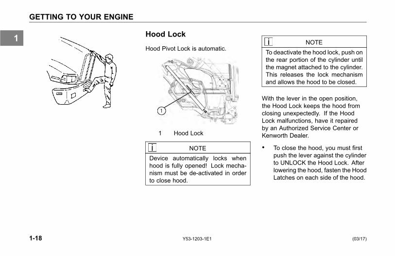
Hood Lock
Hood Pivot Lock is automatic.
1 Hood Lock
NOTEDevice automatically locks whenhood is fully opened! Lock mecha-nism must be de-activated in orderto close hood.
NOTETo deactivate the hood lock, push onthe rear portion of the cylinder untilthe magnet attached to the cylinder.This releases the lock mechanismand allows the hood to be closed.
With the lever in the open position,the Hood Lock keeps the hood fromclosing unexpectedly. If the HoodLock malfunctions, have it repairedby an Authorized Service Center orKenworth Dealer.
• To close the hood, you must firstpush the lever against the cylinderto UNLOCK the Hood Lock. Afterlowering the hood, fasten the HoodLatches on each side of the hood.
1-18 Y53-1203-1E1 (03/17)
1

GETTING TO YOUR ENGINE
WARNING!If the hood falls, anyone under itcould be injured. Always attach thesafety cable and/or hood stop whenthe hood is in its open position anytime anyone gets under the hood forany reason.
WARNING!If the hood is not latched securely,it could open during operation andcause an accident. Be sure the hoodis latched securely before movingthe vehicle. Failure to comply mayresult in personal injury, death, orequipment damage.
Hood Safety Cable
Attach safety cable here
Attached cable
WARNING!If the hood falls, anyone under itcould be injured. Always attach thesafety cable and/or hood stop whenthe hood is in its open position anytime anyone gets under the hood forany reason.
CAUTIONBefore lowering the hood, be sureno objects or people are in the way.Look on both sides of the engineand then yell "HOOD DOWN" priorto closing the hood.
WARNING!If the hood is not latched securely,it could open during operation andcause an accident. Be sure the hoodis latched securely before movingthe vehicle.
(03/17) Y53-1203-1E1 1-19
1

SEATS AND RESTRAINTS
SEATS ANDRESTRAINTS
Introduction
This section covers the operationand safe use of your Kenworth seats.For further information on featuresand adjustment of the seat, see themanufacturer's Service and OperationManual included with the vehicle.
Seat Adjustment
WARNING!Do not adjust the driver's seat whilethe vehicle is moving. The seatcould move suddenly and unexpect-edly and can cause the driver tolose control of the vehicle. Make alladjustments to the seat while thevehicle is stopped. After adjustingthe seat and before driving off, al-ways check to ensure that the seatis firmly latched in position. Failureto comply may result in death, per-sonal injury, equipment or propertydamage.
NOTEAfter adjusting the seat and beforedriving off, always check to ensurethat the seat is firmly latched in po-sition.
Standard Driver's Seat
The standard driver's seat can beadjusted forward and rearward as wellas up and down. The seat back anglecan also be adjusted. These threemovements are each controlled bylevers located either beneath or at thesides of the seat.
Driver's Seat with Air Suspension
WARNING!Before driving or riding in vehi-cle, ensure that there is adequatehead clearance at maximum upwardtravel of seat. Injury may occur ifhead clearance is not adequate.Failure to comply may result in per-sonal injury or death.
Reclining Seats
• Make sure the sleeper curtain istied back.
1-20 Y53-1203-1E1 (03/17)
1
SEATS AND RESTRAINTS
• Raise the seat all the way upso that the seat will tilt back andcompletely clear objects behindyou.
WARNING!Do not drive or ride with your seatback in the reclined position. Youcould be injured by sliding under theseat belts in a collision. Failure tocomply may result in personal injuryor death.
Safety Restraint Belts
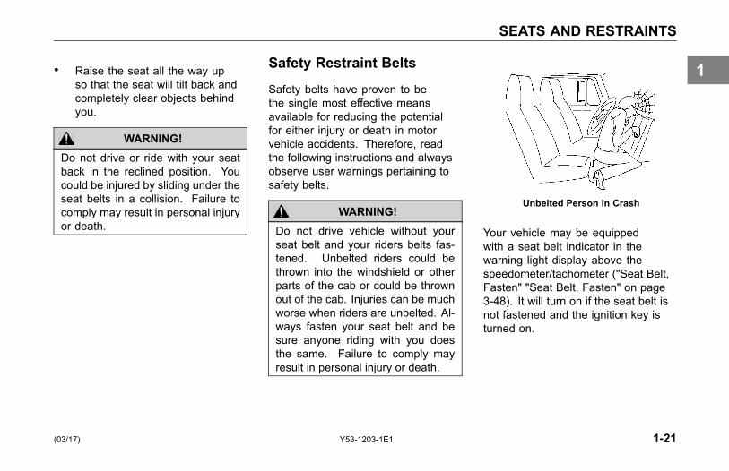
Safety belts have proven to bethe single most effective meansavailable for reducing the potentialfor either injury or death in motorvehicle accidents. Therefore, readthe following instructions and alwaysobserve user warnings pertaining tosafety belts.
WARNING!Do not drive vehicle without yourseat belt and your riders belts fas-tened. Unbelted riders could bethrown into the windshield or otherparts of the cab or could be thrownout of the cab. Injuries can be muchworse when riders are unbelted. Al-ways fasten your seat belt and besure anyone riding with you doesthe same. Failure to comply mayresult in personal injury or death.
Unbelted Person in Crash
Your vehicle may be equippedwith a seat belt indicator in thewarning light display above thespeedometer/tachometer ("Seat Belt,Fasten" "Seat Belt, Fasten" on page3-48). It will turn on if the seat belt isnot fastened and the ignition key isturned on.
(03/17) Y53-1203-1E1 1-21
1
SEATS AND RESTRAINTS
Lap/Shoulder Belt
The combination lap-shoulder belt isequipped with a locking mechanism.The system adjusts automatically to aperson's size and movements as longas the pull on the belt is slow.
Hard braking or a collision locks thebelt. The belt will also lock whendriving up or down a steep hill or in asharp curve.
To fasten the belt:
1. Grasp the belt tongue.
2. Pull belt in a continuous slowmotion across your chest and lap.
3. Insert belt tongue into buckle oninboard side of seat.
4. Push down until the tongue issecurely locked with an audibleclick. Pull belt to check for properfastening.
° Pull shoulder section to makesure belt fits snugly across thechest.
° The shoulder belt must bepositioned over the shoulder,it must never rest against theneck.
° Belts should fit snugly acrossthe pelvis and chest.Make sure any slack is woundup on the retractor.
To unfasten the belt:
• Push in the release button on thebuckle. The belt will spring out ofthe buckle.
• To release a locked belt, lean backto take the body pressure off ofthe belt.
• To store a lap-shoulder belt, allowthe belt to wind up on the retractorby guiding the belt tongue until thebelt comes to a stop.
Proper Safety Belt Adjustment
Your combination lap-shoulder beltmay need adjustment. Adjust safetybelts properly.
• The lap belt should be worn as lowand tight on the hips as possible.Make sure any slack is taken upby the belt mechanism.
• The shoulder belt should fit snuglyacross your body. It shouldbe positioned midway over theshoulder (that is next to the door);it should never rest against yourneck.
1-22 Y53-1203-1E1 (03/17)
1
SEATS AND RESTRAINTS
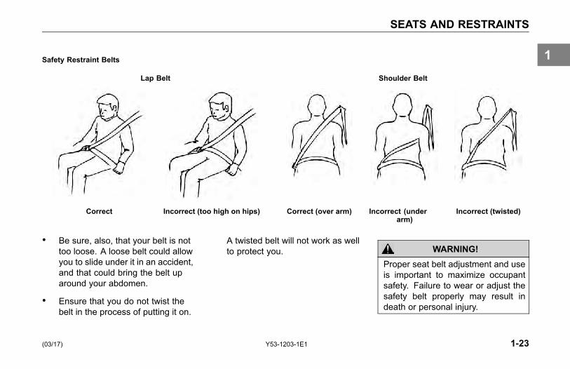
Safety Restraint Belts
Lap Belt Shoulder Belt
Correct Incorrect (too high on hips) Correct (over arm) Incorrect (underarm)
Incorrect (twisted)
• Be sure, also, that your belt is nottoo loose. A loose belt could allowyou to slide under it in an accident,and that could bring the belt uparound your abdomen.
• Ensure that you do not twist thebelt in the process of putting it on.
A twisted belt will not work as wellto protect you. WARNING!
Proper seat belt adjustment and useis important to maximize occupantsafety. Failure to wear or adjust thesafety belt properly may result indeath or personal injury.
(03/17) Y53-1203-1E1 1-23
1
SEATS AND RESTRAINTS
• You can be injured if yourbelt is buckled too high. Ina crash, it would apply forceto your abdomen, not yourpelvic bones. This can result ininternal injuries.
• Do not drive with your seat beltloose. A too-loose seat belt canallow you to fall too far forward,possibly causing head and neckinjuries. You could strike thewheel or the windshield. Adjustyour belt so that there is nomore than 1 in. (25mm) of slack.
WARNING!Do not wear the shoulder part ofbelt under your arm or otherwise outof position. In a crash your bodywould move too far forward, increas-ing the chance of head and neck in-jury. Also, the belt would apply toomuch force to the ribs, which are notas strong as your shoulder bones,and could cause you to suffer inter-nal injuries. Wear the shoulder beltover your shoulder (see Safety Re-straint Belts on page 1-23). Failureto comply may result in personal in-jury or death.
WARNING!Do not twist the belt in the processof putting it on. A twisted belt willnot work as well to protect you. In acrash, the full width of the belt wouldnot be protecting you. A twisted beltcould cut into your body and causeinjuries. Straighten the belt beforebuckling it. If you are unable to wearit without twisting it, have your dealeror service person repair it as soonas possible. Failure to comply mayresult in personal injury or death.
1-24 Y53-1203-1E1 (03/17)
1

SEATS AND RESTRAINTS
Tether Belts
Tether belts are installed on suspensionseats. They help secure the seat to thefloor to restrain it in case of a suddenstop or an accident.
Fixed Tethers
If your Kenworth has been equippedwith fixed length tethers, no manualadjustment is required. The sameinspection and replacement guidelinesshould be used as stated in SafetyRestraint System - Inspection on page5-60.
WARNING!Do not remove, modify, or replacethe tether belt system with a differ-ent tether system. A failed or miss-ing tether belt could allow the seatbase to fully extend in the event ofan accident. Failure to comply mayresult in personal injury or death.
WARNING!Failure to adjust tether belts properlycan cause excessive movement ofthe seat in an accident. Tether beltsshould be adjusted so that they aretaut when the seat is in its most up-ward and forward position. Failureto comply may result in personal in-jury or death.
WARNING!Before driving or riding in a vehi-cle, ensure that there is adequatehead clearance at maximum upwardtravel of seat. Shorten the tether beltas necessary to provide adequatehead clearance. Injury or death mayoccur if head clearance is not ade-quate.
(03/17) Y53-1203-1E1 1-25
1
SEATS AND RESTRAINTS
Tether Adjustment
• Make sure that the tether belt isattached to the cab floor and seatframe. It should be routed throughthe buckle on each side.
• Often the attachments are madeusing a split-type hook. Make sureboth halves of the hook are aroundthe anchor bracket.
• To lengthen the tether, turn thebuckle to a right angle to thewebbing. Then pull the buckle.To shorten the tether, pull on thestrap.
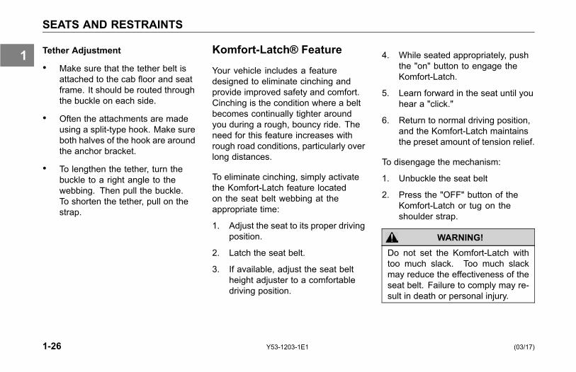
Komfort-Latch® Feature
Your vehicle includes a featuredesigned to eliminate cinching andprovide improved safety and comfort.Cinching is the condition where a beltbecomes continually tighter aroundyou during a rough, bouncy ride. Theneed for this feature increases withrough road conditions, particularly overlong distances.
To eliminate cinching, simply activatethe Komfort-Latch feature locatedon the seat belt webbing at theappropriate time:
1. Adjust the seat to its proper drivingposition.
2. Latch the seat belt.
3. If available, adjust the seat beltheight adjuster to a comfortabledriving position.
4. While seated appropriately, pushthe "on" button to engage theKomfort-Latch.
5. Learn forward in the seat until youhear a "click."
6. Return to normal driving position,and the Komfort-Latch maintainsthe preset amount of tension relief.
To disengage the mechanism:
1. Unbuckle the seat belt
2. Press the "OFF" button of theKomfort-Latch or tug on theshoulder strap.
WARNING!Do not set the Komfort-Latch withtoo much slack. Too much slackmay reduce the effectiveness of theseat belt. Failure to comply may re-sult in death or personal injury.
1-26 Y53-1203-1E1 (03/17)
1
SEATS AND RESTRAINTS
Komfort-Latch®
More information and videotutorials can be found at:www.clicktugsnug.com
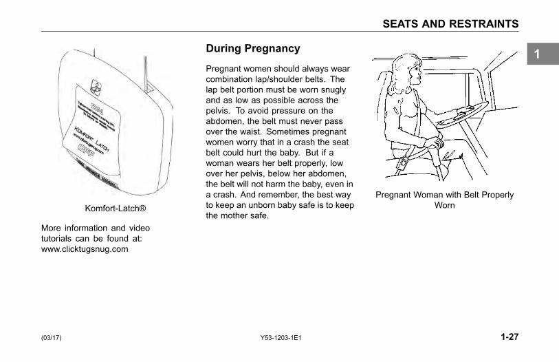
During Pregnancy
Pregnant women should always wearcombination lap/shoulder belts. Thelap belt portion must be worn snuglyand as low as possible across thepelvis. To avoid pressure on theabdomen, the belt must never passover the waist. Sometimes pregnantwomen worry that in a crash the seatbelt could hurt the baby. But if awoman wears her belt properly, lowover her pelvis, below her abdomen,the belt will not harm the baby, even ina crash. And remember, the best wayto keep an unborn baby safe is to keepthe mother safe.
Pregnant Woman with Belt ProperlyWorn
(03/17) Y53-1203-1E1 1-27
1
SEATS AND RESTRAINTS
Belt Damage and Repair
Damaged belts in the cab mustbe replaced. Belts that have beenstretched, cut, or worn out may notprotect you in an accident.
If any seat belt is not working properly,see an Authorized Service Center forrepair or replacement.
For further information on seat beltsand seat belt maintenance, see SafetyRestraint System - Inspection on page5-60.
Safety Restraint Tips• Anyone riding in your vehicle
should wear a seat belt. Aresponsible operator sees to itthat everyone in the vehicle ridessafely and that means with a seatbelt.
• Do not wear a belt over rigid orbreakable objects in or on yourclothing, such as eye glasses,pens, keys, etc., as these maycause injury in an accident.
• Several layers of heavy clothingmay interfere with properpositioning of belts and reducethe overall effectiveness of thesystem.
• Any authorized person sleepingin your vehicle while it is movingshould use the bunk restraint.
• Any authorized person sitting inthe sleeper area on the sofa bed
(if equipped) while it is movingshould wear a seat belt.
• A responsible operator sees to itthat everyone in the vehicle ridesor sleeps safely. The operatoris responsible to inform anypassengers or co-drivers how toproperly use the seat belts andbunk restraint in the vehicle.
• Do not strap in more than oneperson with each belt.
• Keep seat belt and bunk restraintbuckles free of any obstructionthat may prevent secure locking.
• Damaged or worn belts in the cabor sleeper, subjected to excessivestretch forces from normal wear,must be replaced. They maynot protect you if you have anaccident.
• Any belts or restraints that havebeen subjected to an accident
1-28 Y53-1203-1E1 (03/17)
1
SEATS AND RESTRAINTS
should be inspected for any loose(attaching) hardware or damagedbuckles.
• If belts show damage to any partof assembly, such as webbing,bindings, buckles or retractors,they must be replaced.
• Do not allow safety belts (seator bunk) to become damaged bygetting caught in door, bunk orseat hardware, or rubbing againstsharp objects.
• All belts must be kept clean or theretractors may not work properly.
• Never bleach or dye seat or bunkrestraint belts: chemicals canweaken them. Do, however, keepthem clean by following the carelabel on the belts. Let them drycompletely before allowing themto retract or be stowed away.
• Make sure the seat belts andbunk restraint of the unoccupiedpassenger seat or bunk is fullywound up on its retractor oris stowed, so that the belt orrestraint tongue is in its properlystowed position. This reduces thepossibility of the tongue becominga striking object in case of asudden stop.
• Do not modify or disassemble theseat belts or bunk restraint in yourvehicle. They will not be availableto keep you and your passengerssafe.
• If any seat belt or bunk restraintis not working properly, see anauthorized dealer for repair orreplacement.
Sleeper Bunks andRestraints
For Kenworth cabs equipped with asleeper, be sure to use the restraintdevices when the vehicle is in motion.Your vehicle may have belts and/or anet restraint system which are over thebunk or cover the opening.
If your vehicle has an upper and lowerbunk, the upper bunk can be folded upout of the way to provide you with moreroom in the sleeper. Fold the upperbunk up and insert the metal end of thebunk retaining belts into the buckles.Check to be sure the lower bunk is inthe down position.
(03/17) Y53-1203-1E1 1-29
1

SEATS AND RESTRAINTS
WARNING!Be sure the restraint system isused when anyone is occupying thesleeper while the vehicle is moving.In an accident, an unrestrained per-son lying in a sleeper bunk could beseriously injured. He or she couldbe thrown from the bunk. Failureto comply may result in personalinjury, death, equipment or propertydamage.
Lower:
WARNING!Always keep the lower bunk in itsdown position while the vehicle ismoving. If left open, stored itemscould become loose during an acci-dent and strike you, causing seriousdamage or injury.
Upper:
WARNING!Be sure the latch that holds the up-per bunk in the folded position isworking properly so the bunk will notfall down. Pull on the bunk to be sureit is latched securely. If the bunkfalls, you could be injured. Failure tocomply may result in personal injury,death, equipment or property dam-age.
WARNING!Be sure no one ever rides in theupper bunk. That person could bethrown out in an accident and couldbe very seriously injured. The up-per bunk is not equipped with a re-straint system. Do not use the up-per bunk while you are moving. Fail-ure to comply may result in personalinjury, death, equipment or propertydamage.
1-30 Y53-1203-1E1 (03/17)
1
SEATS AND RESTRAINTS
NOTEPer FMCSR 392.60 - UnauthorizedPersons Not to be Transported.Federal law prohibits the trans-portation of persons in commercialvehicles unless they are specificallyauthorized in writing by the motorcarrier. See the cited FMCSR for acomplete description of the regula-tion and exemptions.
• Be sure to stow away all loosebelongings before you move yourvehicle. And do not store objectson the bunks—they could causeserious damage or injury in anaccident.
• Any authorized person sleepingin your vehicle while it is movingshould use the bunk restraint.
• Any authorized person sitting inthe sleeper area on the sofa bed
(if equipped) while it is movingshould wear a seat belt.
• A responsible operator sees to itthat everyone in the vehicle ridesor sleeps safely -and that meanswith a seat belt or bunk restraint.The operator is responsibleto inform any passengers orco-drivers how to properly use theseat belts and bunk restraint in thevehicle.
• Do not strap in more than oneperson with each belt.
• Do not wear a belt over rigid orbreakable objects in or on yourclothing, such as eye glasses,pens, keys, etc., as these maycause injury in an accident.
• Several layers of heavy clothingmay interfere with properpositioning of belts and reducethe overall effectiveness of thesystem.
• Keep seat belt and bunk restraintbuckles free of any obstructionthat may prevent secure locking.
• Damaged or worn belts in the cabor sleeper, subjected to excessivestretch forces from normal wear,must be replaced. They maynot protect you if you have anaccident.
• Any belts or restraints that havebeen subjected to an accidentshould be inspected for any loose(attaching) hardware or damagedbuckles.
• If belts show damage to any partof assembly, such as webbing,bindings, buckles or retractors,they must be replaced.
• Do not allow safety belts (seator bunk) to become damaged bygetting caught in door, bunk orseat hardware, or rubbing againstsharp objects.
(03/17) Y53-1203-1E1 1-31
1

SEATS AND RESTRAINTS
• All belts must be kept clean or theretractors may not work properly.
• Never bleach or dye seat or bunkrestraint belts: chemicals canweaken them. Do, however, keepthem clean by following the carelabel on the belts. Let them drycompletely before allowing themto retract or be stowed away.
• Make sure the seat belts andbunk restraint of the unoccupiedpassenger seat or bunk is fullywound up on its retractor oris stowed, so that the belt orrestraint tongue is in its properlystowed position. This reduces thepossibility of the tongue becominga striking object in case of asudden stop.
• Do not modify or disassemble theseat belts or bunk restraint in yourvehicle. They will not be available
to keep you and your passengerssafe.
• If any seat belt or bunk restraintis not working properly, see anauthorized Kenworth Dealer forrepair or replacement.
Upper Rear Sleeper Storage
Your Kenworth may be equipped withan upper storage shelf that extendsover the lower bunk and across therear of the sleeper. The followingcaution applies:
CAUTIONThe shelf is not intended for person-nel use or storage of items weigh-ing over 75 pounds total. The upperstorage shelf is only intended for softlightweight items such as bedding,duffel bags and clothing. Storage ofhard or heavy itemsmay cause shelfto collapse and/ or fall out in a sud-den stop that could cause personalinjury.
1-32 Y53-1203-1E1 (03/17)
1

START-UP
START-UP
Introduction
The following section covers start-upprocedures for getting your Kenworthready for the road.
Safe Vehicle Operation
For your safety, as well as thosearound you, be a responsible driver:
• If you drink, do not drive.
• Do not drive if you are tired, ill, orunder emotional stress.
Much has gone into the manufacturingof your Kenworth, including advancedengineering techniques, rigid qualitycontrol, and demanding inspections.These manufacturing processes willbe enhanced by you, the safe driver,who observes the following:
• knows and understands how tooperate the vehicle and all itscontrols
• maintains the vehicle properly
• uses driving skills wisely
For more information, refer toDepartment of Transportation
Regulation 392.7, which states thatinterstate commercial motor vehiclesare not to be driven unless the driver issure that certain parts and accessoriesare in working order.
WARNING!Do not drive after drinking alcohol orusing other substances that may af-fect the senses, including prescrip-tion medications. Your reflexes, per-ceptions, and judgment can be af-fected by even a small amount of al-cohol or other substances, and cancause a serious or even fatal acci-dent. Failure to comply may result indeath, personal injury, or equipmentand property damage.
(03/17) Y53-1203-1E1 1-33
1
START-UP
WARNING!The use of alcohol, drugs, and cer-tain medications will seriously im-pair perception, reactions, and driv-ing ability. These circumstances cansubstantially increase the risk of anaccident. Failure to comply may re-sult in death, personal injury, equip-ment or property damage.
WARNING!Do not text while driving. Your re-flexes, perceptions, and judgmentcan be affected while texting orusing any other form of mobile mes-saging while driving. Failure to com-ply may result in death, personalinjury, or equipment and propertydamage.
Vehicle Loading
Compare your vehicle's load capacitywith the total load you are carrying. Ifadjustments need to be made, makethem, do not drive an overloadedvehicle. If you are overloaded or yourload has shifted, your vehicle may beunsafe to drive.
WARNING!Do not exceed the specified load rat-ing. Overloading can result in lossof vehicle control, either by causingcomponent failures or by affectingvehicle handling. Exceeding loadratings can also shorten the servicelife of the vehicle. Failure to com-ply may result in personal injury ordeath.
• The components of yourvehicle are designed to providesatisfactory service if thevehicle is not loaded in excessof either the gross vehicle
weight rating (GVWR), or themaximum front and rear grossaxle weight ratings (GAWRs).(Axle weight ratings are listedon the driver's door edge.)
The following are some definitions ofweight you should know:
GVWR: is the Gross Vehicle WeightRating. This is the MAXIMUMWEIGHT your vehicle is allowed tocarry, including the weight of the emptyvehicle, loading platform, occupants,fuel, and any load. Never exceed theGVWR of your vehicle.
GCW: is the actual combined weight,or Gross Combination Weight (GCW),of your vehicle and its load: vehicle,plus trailer(s), plus cargo.
GAWR: is the Gross Axle WeightRating. This is the total weight thatone axle is designed to transmit to the
1-34 Y53-1203-1E1 (03/17)
1

START-UP
ground. You will find this number listedon the driver's door edge.
Load Distribution: be sure any loadyou carry is distributed so that no axlehas to support more than its GAWR.
WARNING!An unevenly distributed load or aload too heavy over one axle can af-fect the braking and handling of yourvehicle, which could result in an ac-cident. Even if your load is under thelegal limits, be sure it is distributedevenly. Failure to comply may resultin personal injury, death, equipmentor property damage.
Emergency Equipment
It is good practice to carry anemergency equipment kit in yourvehicle. One day, if you have aroadside emergency, you will be gladthe following items are with you:
• window scraper
• snow brush
• container or bag of sand or salt
• emergency light
• triangles
• small shovel
• first aid kit
• fire extinguisher
• vehicle recovery hitches (seeVehicle Recovery Guidelines onpage 2-12 for details).
Driver's Check List
To keep your Kenworth in top shapeand maintain a high level of safetyfor you, your passengers, and yourload, make a thorough inspectionevery day before you drive. You willsave maintenance time later, and thesafety checks could help prevent aserious accident. Please remember,too, that Federal Motor Carrier SafetyRegulation 392.7 requires a pre-tripinspection and so do commercialtrucking companies.
You are not expected to become aprofessional mechanic. The purposeof your inspections is to find anythingthat might interfere with the safe andefficient transportation of yourself, anypassengers, and your load. If you dofind something wrong and cannot fix ityourself, have an authorized KenworthDealer or qualified mechanic repairyour vehicle right away.
(03/17) Y53-1203-1E1 1-35
1

START-UP
The following operations are to beperformed by the driver. Performingthese checks and following themaintenance procedures in thismanual will help keep your Kenworthrunning properly.
Approaching Your Vehicle
• Check the overall appearance andcondition. Are windows, mirrors,and lights clean and unobstructed?
• Check beneath the vehicle. Arethere signs of fuel, oil, or waterleaks?
• Check for damaged, loose, ormissing parts. Are there partsshowing signs of excessive wearor lack of lubrication? Have aqualified mechanic examine anyquestionable items and repairthem without delay.
• Check your load. Is it securedproperly?
Daily ChecksEngine Compartment Checks - Daily
1. Engine Fluid Levels - add more ifnecessary.
° Engine oil
° Coolant (check while engineis cold)
° Power steering fluid level
2. Engine Belt - check tension andcondition of belts. This is importantto ensure proper air compressorand engine operation.
° Measure the belt tensionat the longest span of thebelt. See Accessory DriveBelts on page 5-96 for furtherinformation on checking belttension.
1-36 Y53-1203-1E1 (03/17)
1
START-UP
NOTEDeflection should be one belt thick-ness for each foot distance betweenthe pulley centers.
° If breaks or tears are found,the belt should be replacedbefore operating the vehicle.
3. Fuel Filter/Water SeparatorDraining - check and drain.Depending on the fuel storagefacility, more frequent drainingmay be required.
4. Windshield washer reservoir fluidlevel - fill if necessary.
5. Battery Cables - check thecondition of the battery andalternator cables for signs ofchafing or rubbing. Make surethat all clamps (straps) holding thecables are present and in goodworking order.
6. Hood closed before entering cab.Is it latched properly?
Chassis and Cab Checks - Daily
Before entering the cab and operatingthe vehicle, check the followingequipment for proper maintenance:
1. Lights - do headlights, turn signals,emergency flashers, and exteriorlamps function and are they cleanand adjusted properly?
2. Windows and Mirrors - are theyclean and adjusted properly?
3. Tires and Wheels - are theyinflated properly? Are all wheelcap nuts in place and torquedproperly - tighten if necessary.Check front wheel bearing oillevels. Inspect all tires and wheelsfor damage - correct if found.
4. Suspension - check for loose ormissing fasteners. Check damage
to springs or other suspensionparts.
5. Brake Components - check lines,linkages, chambers, parking andservice brake operation.
6. Air System - are there leaks?
° Air Tanks - drain water fromall air tanks. Make sure thedrain cocks are closed. Thisprocedure is also required forair suspension tanks equippedwith automatic drain valves.
° For further details, see Usingthe Brake System on page4-16.
7. Steps and Handholds - checkfor worn surfaces and loose ormissing fasteners.
8. Fluid Tanks - check underneaththe vehicle for signs of fluid leaks.If any are found, correct beforeoperating the vehicle.
(03/17) Y53-1203-1E1 1-37
1
START-UP
9. Fuel Tank Caps - are they secure?
WARNING!Do not remove a fuel tank cap nearan open flame. Diesel fuel in thepresence of an ignition source (suchas a cigarette) could cause an explo-sion. A mixture of gasoline or alcoholwith diesel fuel increases this risk ofexplosion. Use only the fuel and/oradditives recommended for your en-gine. Failure to comply may result inpersonal injury, death, equipment orproperty damage. See Refueling onpage 4-80, for more information.
10. Trailer Connections - are theysecure and the (Tractor) linesclear? If they are not being used,are they stored properly?
° Is the trailer spare wheelsecure and inflated?
° Is the landing gear up and thehandle secured?
11. Check the fifth wheel. Is thekingpin locked?
° Is the sliding fifth wheellocked?
Cab Interior - Daily
1. Seat - adjust the seat for easyreach of controls.
2. Seat Belts - fasten and adjustsafety restraint belts.
3. Sleeper Restraints - check andinspect condition.
4. Steering Column - adjust for easyreach.
5. Mirrors - check and readjustmirrors if necessary.
6. Lights - turn ignition key to the ONposition and check for warninglights and buzzer. Check operationof turn signals and emergencylights.
7. Instruments - check allinstruments.
8. Windshield - check operation ofwindshield wipers and washers.
9. Horn - check operation of horn.
10. Sleeper and LuggageCompartment - all loose itemsstowed securely.
° Is the fire extinguisher fullycharged?
° Is your road emergency kitcomplete?
° Compartments closed?
11. Fuel - check fuel. Is there enoughfuel?
12. Diesel Exhaust Fluid (DEF) -check level. Is there enough fluid?
1-38 Y53-1203-1E1 (03/17)
1

START-UP
NOTEThe above items (Engine Compart-ment, Chassis and Cab, and PrestartChecks) should be checked daily, asa minimum. They are in addition to,not in place, of Federal Motor CarrierSafety Regulations. These regula-tions may be purchased by writing to:Superintendent of Documents,U.S. Government Printing Office,Washington, DC 20402
Weekly Operations
1. Battery - check battery andterminals.
2. Wheel Cap Nuts - are they allin place and torqued properly -tighten if necessary. See WheelCap Nut Torque on page 5-131.
3. Other Controls and Wiring - checkfor condition and adjustment.
4. Steering Components - checkpitman arm, draglink, and powersteering hoses, etc., for loose,broken, or missing parts.
5. Other Engine CompartmentChecks.
• Check condition and fastening ofengine belt, hoses, clamps, andradiator.
• Check the air cleaner, muffler, andexhaust pipes. Are they tight andsecure?
• After Engine Warm-up.
° Automatic Transmission- check fluid level in theautomatic transmission oil (ifequipped).
(03/17) Y53-1203-1E1 1-39
1


EMERGENCY
WHAT TO DO IF...You Need Roadside Assistance. . . . . . . . . . 2-3Low Air Alarm Turns On . . . . . . . . . . . . . 2-3Stop Engine Lamp Turns On . . . . . . . . . . . 2-4Engine Oil Pressure Lamp Turns On. . . . . . . . 2-4Check Engine Lamp Turns On . . . . . . . . . . 2-5Engine is Overheating . . . . . . . . . . . . . . 2-5Fuse or Relay Blows . . . . . . . . . . . . . . 2-7
JUMP STARTING VEHICLESIntroduction . . . . . . . . . . . . . . . . . . 2-9
VEHICLE RECOVERY AND SPRING BRAKESIntroduction . . . . . . . . . . . . . . . . . 2-12Vehicle Recovery Instructions . . . . . . . . . 2-12Recovery Rigging . . . . . . . . . . . . . . . 2-14Returning Vehicle to Service . . . . . . . . . . 2-14Spring Brakes - Manual Release . . . . . . . . 2-15Freeing the Vehicle from Sand, Mud, Snow and Ice 2-17
(03/17) Y53-1203-1E1 2-1
2

WHAT TO DO IF...
WHAT TO DO IF...
You Need RoadsideAssistance
Call toll-FREE 1-800-KW-ASSIST(1-800-592-7747) to talk to someoneat the PACCAR Customer Center.
• Open 24-7-365 days a year.
• They can help you get roadsideassistance.
• They have a custom mappingsystem which locates Kenworth &Peterbilt Dealers and IndependentService Providers (ISPs) near youand lists types of services offered,hours of operation and contactinformation.
• They can assist with jump andpull starts, tires, trailers, fines andpermits, chains, towing, hazardousclean-up, out of fuel (roadside),mechanical repairs and preventivemaintenance services.
• They have bilingual agents andaccess to a translation serviceto ensure quality assistancefor customers who speak anylanguage.
• They can’t answer your warrantyquestions but can get you incontact with a Kenworth dealerwho can.
• The PACCAR Customer Centerservice is FREE even if you don’tdrive a Kenworth.
Low Air Alarm Turns On1. Slow down carefully.
2. Move a safe distance off the roadand stop.
3. Place the transmission inneutral (park with automatictransmissions, if equipped) andset the parking brake. (Referto Parking Brake Valve on page3-107 and OPERATING THETRANSMISSION on page 4-70,for transmission shifting andparking brake information.)
4. Turn OFF the engine.
5. Turn ON the emergency flasherand use other warning devices toalert other motorists.
(03/17) Y53-1203-1E1 2-3
2

WHAT TO DO IF...
WARNING!If the air pressure falls below 60psi (414 kPa) the spring brakesmay stop the vehicle abruptly, whichcould cause an accident resultingin personal injury or death. Ob-serve the red warning lamps on thegauges. If one comes on, do notcontinue to drive the vehicle until ithas been properly repaired or ser-viced.
If the light and alarm do not turn offat startup, do not try to drive thevehicle until the problem is found andfixed. (Refer to USING THE BRAKESYSTEM on page 4-16, for more brakeinformation.)
Stop Engine Lamp Turns On
WARNING!This should be considered an emer-gency. You should stop the vehi-cle as safely as possible and turnOFF the ignition. The vehicle mustbe serviced and the problem cor-rected before driving again. Failureto do somay cause severe engine orDPF damage, or cause an accidentwhich may result in personal injuryor death.
If the Stop Engine warning lampilluminates, it means you have aserious engine system problem.
Engine Oil Pressure LampTurns On
1. Slow down carefully.
2. Move a safe distance off the roadand stop.
3. Place the transmission in parkand set the parking brake. (SeeParking Brake Valve on page3-107 and OPERATING THETRANSMISSION on page 4-70,for transmission shifting andparking brake information.)
4. Turn OFF the engine.
5. Turn ON the emergency flasherand use other warning devices toalert other motorists.
2-4 Y53-1203-1E1 (03/17)
2

WHAT TO DO IF...
6. Wait a few minutes to allow oil todrain into the engine oil pan, andthen check the oil level. (See OilLevel Check on page 5-91, fordetails on checking oil level.)
7. Add oil if necessary. If the problempersists, contact an authorizedKenworth dealer as soon aspossible.
CAUTIONContinuing to operate your vehiclewith insufficient oil pressure maycause severe engine damage orcause an accident which may resultin equipment or property damage.
It is important to maintain oil pressurewithin acceptable limits. If oil pressuredrops below the minimum psi a RedWarning Lamp on the oil pressuregauge and the Stop Engine Lamp willcome ON.
Check Engine Lamp TurnsOn
Vehicle should be serviced to correctthe problem but the situation shouldnot be considered an emergency. Thevehicle can still be safely driven.
Engine is Overheating1. Reduce engine speed and safely
stop the vehicle. When stopped,place the transmission in Neutraland set the parking brake. (SeeParking Brake Valve on page3-107 and OPERATING THETRANSMISSION on page 4-70,for transmission shifting andparking brake information.) Keepthe engine running.
2. Check to ensure the Oil PressureGauge reads normal. (See EngineOil Pressure Gauge, on page3-65, for further information.)
3. Make sure the engine fan isturning by switching the EngineFan Switch from AUTO to MAN(Manual).
4. Increase the engine speed toabout one-half of full operatingspeed, or 1,100 to 1,200 rpm,maximum.
(03/17) Y53-1203-1E1 2-5
2
WHAT TO DO IF...
5. Return the engine speed to normalidle after 2 or 3 minutes.
6. Monitor the engine temperature.After the temperature returns tonormal, allow the engine to idle3 to 5 minutes before shutting itoff. This allows the engine to coolgradually and uniformly.
7. If overheating came fromsevere operating conditions, thetemperature should have cooledby this time. If it has not, stopthe engine and let it cool beforechecking to see if the coolant islow.
° Wait until the coolanttemperature is below 122° F(50° C).
° Protect face, hands, and armsby covering the cap with alarge, thick rag to protectagainst escaping fluid andsteam.
° Carefully and slowly turnthe cap one-quarter of aturn or until it reaches thefirst stop—allowing excesspressure to escape—pushdown and turn for finalremoval.
See Topping Up on page 5-65, forinstructions on checking and filling thecoolant expansion tank.
WARNING!Do not remove the radiator fill capwhile the engine is hot. Scaldingsteam and fluid under pressure mayescape. You could be badly burned.Failure to comply may result in per-sonal injury or death.
WARNING!To reduce the chance of death,personal injury, fire and/or vehicledamage from overheated engines,never leave the engine idling withoutan alert driver present. If the en-gine should overheat, as indicatedby the engine coolant temperaturelight, immediate action is requiredto correct the condition. Continuedunattended operation of the engine,even for a short time, may resultin serious engine damage or a fire.Failure to comply may result in per-sonal injury, death, equipment orproperty damage.
2-6 Y53-1203-1E1 (03/17)
2

WHAT TO DO IF...
Fuse or Relay Blows
Fuses, circuit breakers, and relaysare located in the Power DistributionBox to the left of the steering columnbehind the clutch pedal. See PowerDistribution Box on page 5-74.
Additional fuses for the alternator,engine electronics and trailer batterycharge circuit may be located in thePower Distribution Center (PDC)inside the battery box and/ or on theengine side of the cab firewall. SeePower Distribution Center (PDC) onpage 5-71.
WARNING!Do not replace a fuse with a fuse of ahigher rating. Doing somay damagethe electrical system and cause afire. Failure to comply may result inpersonal injury, death, equipment orproperty damage.
CAUTIONBefore replacing a fuse, turn OFF alllights and accessories and removethe ignition key to avoid damagingthe electrical system.
CAUTIONNever patch fuses with tin foil orwire. This may cause serious dam-age elsewhere in the electrical cir-cuit, and it may cause a fire.
CAUTIONIf a circuit keeps blowing fuses, havethe electrical system inspected for ashort circuit or overload by an au-thorized Kenworth dealer as soonas possible. Failure to do so couldcause serious damage to the elec-trical system and/or vehicle.
NOTEIf a fuse of the same rating is notavailable, a fuse of a lower ratingmay be temporarily substituted. Youcan also use a fuse from a circuit youcan do temporarily without (for ex-ample an accessory circuit or radio).
All the electrical circuits have fusesto protect them from a short circuit oroverload. If something electrical onyour chassis stops working, the firstthing you should check for is a blownfuse.
1. TurnOFF all lights and accessoriesand remove the ignition key toavoid damaging the electricalsystem.
2. Determine from the chart on thefuse panel which fuse controls thatcomponent.
(03/17) Y53-1203-1E1 2-7
2
WHAT TO DO IF...
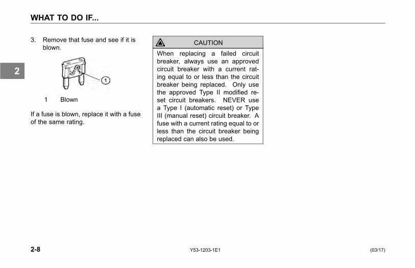
3. Remove that fuse and see if it isblown.
1 Blown
If a fuse is blown, replace it with a fuseof the same rating.
CAUTIONWhen replacing a failed circuitbreaker, always use an approvedcircuit breaker with a current rat-ing equal to or less than the circuitbreaker being replaced. Only usethe approved Type II modified re-set circuit breakers. NEVER usea Type I (automatic reset) or TypeIII (manual reset) circuit breaker. Afuse with a current rating equal to orless than the circuit breaker beingreplaced can also be used.
2-8 Y53-1203-1E1 (03/17)
2
JUMP STARTING VEHICLES
JUMP STARTINGVEHICLES
Introduction
Because of the various batteryinstallations and electrical systemoptions, Kenworth does notrecommend that you attempt tojump start your vehicle. If you have abattery problem, it is best to contact aKenworth Dealer or a reputable towingservice.
However, if your battery is discharged(dead), you may be able to start itby using energy from a good batteryin another vehicle. This is termedjump starting. Be sure to follow theprecautions and instructions below.
WARNING!Batteries contain acid that can burnand gasses that can explode. Ignor-ing safety procedures may result inpersonal injury, death, equipment orproperty damage.
WARNING!Never jump start a battery near fire,flames, or electrical sparks. Bat-teries generate explosive gasesthat could explode. Keep sparks,flame, and lighted cigarettes awayfrom batteries. Failure to complymay result in personal injury, death,equipment or property damage.
WARNING!Never remove or tamper with batterycaps. Ignoring this could allow bat-tery acid to contact eyes, skin, fab-rics, or painted surfaces. Failure tocomply may result in personal injury,death, equipment or property dam-age.
• Be careful that metal tools (orany metal in contact with thepositive terminal) do not contactthe positive battery terminal andany other metal on the vehicleat the same time. Remove metaljewelry and avoid leaning overthe battery.
• If metal jewelry or other metalcomes in contact with electricalcircuits, a short circuit mayoccur causing you to be injured,as well as electrical systemfailure and damage to thevehicle.
(03/17) Y53-1203-1E1 2-9
2
JUMP STARTING VEHICLES
To Jump Start Your Vehicle
WARNING!The voltage of the booster bat-tery must have a 12 volt rating andthe capacity of the booster batteryshould not be lower than that of thedischarged battery. Use of batteriesof different voltage or substantiallydifferent capacity rating may causean explosion. Failure to complymay result in personal injury, death,equipment or property damage.
CAUTIONApplying a higher voltage boosterbattery will cause expensive dam-age to sensitive electronic compo-nents, such as relays, and the ra-dio. Failure to comply may result inequipment damage.
• Improper hook-up of jumpercables or not following theseprocedures can damage thealternator or cause seriousdamage to both vehicles.
WARNING!To avoid personal injury and dam-age to the vehicle, heed all warningsand instructions of the jumper cablemanufacturer.
• The jumper cables must be longenough so that the vehicles donot touch.
Preparing the vehicles:
1. Position the two vehicles together,but do not allow them to touch.
2. Turn OFF all lights, heater, radio,and any other accessory on bothvehicles.
3. Set the parking brakes: pull outthe Yellow button located on thedash.
4. Shift the transmission into parkposition or neutral for manualtransmissions. (See OPERATINGTHE TRANSMISSION on page4-70 and Parking Brake Valveon page 3-107, for transmissionshifting and parking brakeinformation.)
5. If either vehicle is equipped withbattery disconnects ensure theyare in the "OFF" position prior toconnecting the two vehicles.
2-10 Y53-1203-1E1 (03/17)
2
JUMP STARTING VEHICLES
Connect the batteries:
1. Attach one end of a jumper cableto the positive (+) terminal of thedischarged (dead) battery. Thiswill have a large red + or P on thebattery case, post, or clamp.
2. Attach the other end of the samecable to the positive (+) terminalof the good (booster) battery.
3. Attach the remaining jumper cableFIRST to the negative (-) terminal(black or N) of the good battery.
4. Attach the other end of thenegative cable to a bare metal partnot bolted to the engine block.IMPORTANT: Always connectpositive (+) to positive (+) andnegative (-) to negative (-).
5. If either vehicle is equipped withbattery disconnects, ensure thatthey are in the "ON" position.
6. Start the engine:
• Start the vehicle that has thegood battery first. Let it run for 5minutes.
• Then start the vehicle that has thedischarged (dead) battery.If the engine fails to start, do notcontinue to crank the starter butcontact the nearest authorizedKenworth Dealer.
Remove jumper cables:
WARNING!When disconnecting jumper cables,make sure they do not get caughtin any moving parts in the enginecompartment. You could be injured.
• Reverse the above procedureexactly when removing the jumpercables. With engine running,disconnect jumper cables fromboth vehicles in the exact reverseorder (Steps 4-1), making sureto first remove the negativecable from the vehicle with thedischarged battery.
(03/17) Y53-1203-1E1 2-11
2
VEHICLE RECOVERY AND SPRING BRAKES
VEHICLE RECOVERYAND SPRING BRAKES
Introduction
Your Kenworth may be equipped with aRecovery Device(s) designed for shortdistance recovery purposes only. Useonly the original Kenworth recoverydevice(s) and the instructions below.If your vehicle does not have theproper device contact your authorizedKenworth Dealer.
Vehicle RecoveryInstructions
Refer to the instructions below whentowing your vehicle:
• Use proper towing equipment toprevent damage to the vehicle.
CAUTIONConnect only to the Recovery De-vice(s), as described on the follow-ing pages. Do not attach to bumpersor brackets. Use only equipment de-signed for this purpose. Connec-tions to other structural parts coulddamage the vehicle.
CAUTIONRemove the driveline and axleshafts or lift the driving wheels offthe ground before towing the ve-hicle. See Driver Controlled MainDifferential Lock on page 4-60. Alllubricating and clutch applicationoil pressure is provided by an en-gine-driven pump, which will notwork when the engine is stopped.You could seriously damage yourvehicle by towing it with the drivelineconnected and the drive wheels onthe ground.
2-12 Y53-1203-1E1 (03/17)
2

VEHICLE RECOVERY AND SPRING BRAKES
CAUTIONWhen vehicles are towed, either bywrecker or piggy-back, the lubricantin the top front of the drive axle willdrain to the rear. This will leave thetop components dry. The resultingfriction may seriously damage them.Always remove the main driveshaftand axle shafts before towing yourvehicle.
• See the following references:
° Recovery Rigging on page2-14.
° Driver Controlled MainDifferential Lock on page4-60.
• Use a safety chain system.
• Disconnect driveline.
• Follow state/provincial and locallaws that apply to vehicles in tow.
• Do not tow vehicles at speeds inexcess of 55 mph (90 km/h).
NOTEFor additional information concern-ing heavy duty truck recovery, seeTechnology & Maintenance Council(TMC).
• Recommended Practice #602–A— "Front Towing Devices ForTrucks and Tractors."
• Recommended Practice #602–B— "Recovery Attachment PointsFor Trucks, Tractors, andCombination Vehicles."
• Recommended Practice #626— "Heavy Duty Truck TowingProcedures."
Copies of these can be obtained fromthe following address:
Technology & Maintenance Council
950 N. Glebe Road
(703) 838-1763
Arlington, VA 22203
Email: [email protected]
www.trucking.org
(03/17) Y53-1203-1E1 2-13
2

VEHICLE RECOVERY AND SPRING BRAKES
Recovery Rigging
To connect to the Kenworth, follow thesuggested rigging methods below.
• Use a double chain or cable setupthat distributes the load equally
to both hitches. See 1 or 2 in thefollowing illustration.
• Never loop a single chain or cablethrough both hitches (3).
• Use a spreader or equalizer bar todistribute the load on both hitches(1).
• If no spreader bar is available,connect the main tow chain orcable no closer than 6 ft. from thevehicle (2).
1. Spreader Bar or Equalizer 2. Minimum 6 FT. 3. NEVER USE SINGLE CHAIN OR CABLEPreferred Acceptable LOOPED THROUGH TOW DEVICES
Returning Vehicle to Service
Your vehicle may have lost lubricantwhile being towed. To preventdamage, check the oil level and addoil if necessary.
After adding the specified type andamount of lubricant, drive the vehicle.It should be unloaded. Drive 1 to2 miles (1.5 to 3 km) at a speedlower than 25 mph (40 km/h). This
will thoroughly circulate the lubricantthrough the assembly.
2-14 Y53-1203-1E1 (03/17)
2

VEHICLE RECOVERY AND SPRING BRAKES
Spring Brakes - ManualRelease
In order to tow a vehicle, if there isinsufficient air to release the parkingbrake, the spring brakes can bemanually released.
WARNING!Do not drive vehicle with malfunc-tioning brakes. If one of the brakecircuits should become inoperative,braking distances will increase sub-stantially and handling characteris-tics while braking will be affected.You could lose control of your vehi-cle or cause an accident. Have ittowed to the nearest dealer or qual-ified repair facility for repair. Fail-ure to comply may result in personalinjury, death, equipment or propertydamage.
You may sometimes have to releaseyour vehicle's spring brakes by hand.
This could happen if the system airpressure does not reach operatingpressure because your engine orcompressor is not working properly.You will have to release the springbrakes at the spring brake chambers.
WARNING!Do not disassemble a spring brakechamber. These chambers con-tain a powerful spring that is com-pressed. Sudden release of thisspring may result in personal injuryor death.
WARNING!Do not operate a vehicle when thespring brakes have been manu-ally released. Driving a vehicleafter its spring brakes are manu-ally released is extremely danger-ous. The brakes may not func-tion. Failure to comply may resultin personal injury, death, equip-ment or property damage.
WARNING!Releasing the spring brakes onan unsecured vehicle could leadto an accident. The vehicle couldroll, which may result in per-sonal injury, death, equipment orproperty damage. Always securethe vehicle with wheel chocks,chains, or other safe means toprevent rolling before manuallyreleasing the spring brakes.
(03/17) Y53-1203-1E1 2-15
2

VEHICLE RECOVERY AND SPRING BRAKES
To move a vehicle immobilized bythe spring brakes due to loss ofair pressure in the brake system,perform the following procedure:
1. Remove thecap from the springchamber.
2. Remove therelease studassembly from theside pocket, andremove the releasenut and washer fromthe release stud.
3. Slide out therelease stud.
4. Insert the releasestud through theopening in the springchamber where thecap was removed.Insert it into thepressure plate. Turnthe release stud 1/4turn clockwise in thepressure plate. Thissecures the crosspin into the cross pinarea of the pressureplate and locks it intothe manual releaseposition.
5. Assemble therelease stud washerand nut on therelease stud.
6. With a wrench,turn the release studassembly nut until thecompression springis 90-95 percentcaged. While doingthis, check to makesure the push rod(adapter push rodor service pushrod) is retracting.Do not over-torquethe release studassembly. (S-Camtype maximum: 50lb-ft, Wedge typemaximum: 30 lb-ft).The spring brake isnow mechanicallyreleased.
2-16 Y53-1203-1E1 (03/17)
2
VEHICLE RECOVERY AND SPRING BRAKES
Freeing the Vehicle fromSand, Mud, Snow and Ice
If the vehicle gets stuck in sand,mud, snow, or ice:
• Move the gearshift lever orselector from First to Reverse.
• Apply light pressure on theaccelerator pedal while thetransmission is in gear.
• Remove your foot from theaccelerator while shifting.
• Do not race the engine.
• For best traction and safety, avoidspinning the wheels.
WARNING!Do not spin the wheels faster than35 mph (55 km/h). Spinning a tire atspeedometer readings faster than35mph (55 km/h) can be dangerous.Tires can explode from spinning toofast. Under some conditions, a tiremay be spinning at a speed twicethat shown on the speedometer.Any resulting tire explosion couldcause injury or death to a bystanderor passenger, as well as exten-sive vehicle damage: including tire,transmission and/or rear axle mal-function.
Comply with the followinginstructions to avoid transmissiondamage:
• Always start vehicle in motion withthe shift lever in first gear.
• Be sure that transmission is fullyengaged in gear before releasingthe clutch pedal (manual only).
• Do not shift into reverse while thevehicle is moving.
• Do not permit the vehicle to betowed for long distances withoutremoving the driveshaft.
(03/17) Y53-1203-1E1 2-17
2
VEHICLE RECOVERY AND SPRING BRAKES
Tire Chains
If you need tire chains, install them onboth sides of the driving axle.
CAUTIONChains on the tires of only one tan-dem axle can damage the drivelineU-joints and the interaxle differen-tial. Repairs could be costly andtime-consuming. Failure to complymay result in equipment damage.
2-18 Y53-1203-1E1 (03/17)
2
CONTROLS
ACCESSORIESIntroduction . . . . . . . . . . . . . . . . . . 3-5Radio (Option) . . . . . . . . . . . . . . . . . 3-6Cigarette Lighter and Ashtray (Option) . . . . . . . 3-6Clock . . . . . . . . . . . . . . . . . . . . . 3-7Cab Storage . . . . . . . . . . . . . . . . . 3-10
HEATING AND AIR CONDITIONINGIntroduction . . . . . . . . . . . . . . . . . 3-12Precautions . . . . . . . . . . . . . . . . . 3-13Cab Controls . . . . . . . . . . . . . . . . . 3-16Sleeper Heater - A/C Controls (option) . . . . . . 3-19
AUDIBLE ALERTSIntroduction . . . . . . . . . . . . . . . . . 3-22
INDICATORSIntroduction . . . . . . . . . . . . . . . . . 3-28
(03/17) Y53-1203-1E1 3-1
3
CONTROLS
GAUGES AND DISPLAYSIntroduction . . . . . . . . . . . . . . . . . 3-52Multi-Function Display (Option) . . . . . . . . . 3-76
MULTI-FUNCTION DISPLAYIntroduction . . . . . . . . . . . . . . . . . 3-80Alarms, Warning Tones and Visual Indicator Lights 3-80Warning and Information Alert Screens . . . . . 3-81Wingman® ACB Warning Tone / Alert Screens . . 3-85Multi-Function Display . . . . . . . . . . . . . 3-87
SWITCHESIntroduction . . . . . . . . . . . . . . . . . 3-98
STEERING COLUMNIntroduction . . . . . . . . . . . . . . . . . 3-117Turn Signal/High Beam Switch . . . . . . . . . 3-117Windshield Wipers/Washer . . . . . . . . . . . 3-119Trailer Brake Hand Valve. . . . . . . . . . . . 3-121Stop/Turn Signal Lamp Operation . . . . . . . . 3-121
3-2 Y53-1203-1E1 (03/17)
3
CONTROLS
Adjustable Tilt/Telescoping Column . . . . . . . 3-122Horn . . . . . . . . . . . . . . . . . . . . 3-123SmartWheel Multiplex Control System . . . . . . 3-124
MIRRORSIntroduction . . . . . . . . . . . . . . . . . 3-129Power Mirror Switch . . . . . . . . . . . . . . 3-129Mirror Heat Button . . . . . . . . . . . . . . 3-131
(03/17) Y53-1203-1E1 3-3
3


ACCESSORIES
ACCESSORIES
Introduction
1. Radio2. Glove Box
3. Ashtray (Option)4. Cigarette Lighter (Option)
(03/17) Y53-1203-1E1 3-5
3
ACCESSORIES
Radio (Option)
As an option, your vehicle has eitheran AM/FM Stereo Receiver or AM/FMStereo with CD.
For instructions on how to operate yourparticular radio, see the manufacturer'sRadio Operating Instructions.
Cigarette Lighter andAshtray (Option)
NOTEThe cigarette lighter will operate withthe ignition key in either the OFF,ACC (accessory), or ON position.
To operate, push in on the knob endof the lighter. After a few moments,the lighter will automatically pop out,glowing hot and ready to use. Afteruse, insert the lighter back into thesocket without pushing all the way in.
The socket of the cigarette lighter maybe used to operate 12 volt, 15 ampereappliances, such as a hand spotlightor small vacuum cleaner.
WARNING!Do not place paper or other com-bustible substances in an ashtray, itcould cause a fire. Keep all burnablematerials, besides smoking materi-als, out of the ashtray. Failure tocomply may result in personal injury,death, equipment or property dam-age.
WARNING!Do not exceed the voltage/amper-age capacity of the cigarette lighter.It could result in a fire. Follow allwarnings and instructions in the op-erator's manual for the applianceyou are using. Failure to complymay result in personal injury, death,equipment or property damage.
3-6 Y53-1203-1E1 (03/17)
3

ACCESSORIES
ClockDash and Sleeper ClockAnalog Clock - Dash
1 Counter Clockwise2 Clockwise
• Depress right hand button to rotateclock hands clockwise.
• Depress left hand button to rotateclock hands counter clockwise.
• Continue to depress buttons forfaster movement.
Digital Clock - Sleeper
Quick Operating Instructions for Kenworth Digital ClockMode Display Functions Buttons to UseClock Current time (flashing colon)
(note PM in upper left corner)• set time• silence alarm
+, - (hold down to change faster)Select or On/Off
Date Date (MM/DD) • set date - for month, + for day
Alarm Alarm setting (alarm symbol)(steady symbol = alarm On
• set alarm• turn alarm on/off
+, -On/Off
ElapsedTime
Elapsed time (ET displayed)(steady ET = timer On)
• start & stop timer• reset elapsed time
On/Off+ or - when timer is off
Auxiliary AUX in lower left corner • not used
(03/17) Y53-1203-1E1 3-7
3

ACCESSORIES
Clock
Set the time as follows: Press andhold down either the "+" or "-" button tochange the time to the proper setting(note "PM" indicator in upper left cornerof display). After holding down eitherbutton for three seconds, the rate ofchange will increase from slow to fast.The clock will start keeping time assoon as either button is released. Aflashing display indicates that powerhas been interrupted to the clock, andall functions will need to be reset.
The clock mode is the default display,which means the display will return tothis mode after a few seconds fromevery other mode except from elapsedtime mode.
Date
Enter the date mode by pressing the"Select" button once. Set the currentmonth using the "-" button, and thedate by using the "+" button (thedisplay will automatically return to theclock mode after a few seconds).
Alarm
Press the "Select" button twice toswitch to the alarm mode, which isindicated by the alarm symbol on theleft side of the display. The alarm isset in the same manner as the time(again, be careful to note the status ofthe "PM" indicator). Use the "On/Off"button to turn the alarm on and offwhile in this mode. The alarm symbolflashes when the alarm is off, and turnsto steady when the alarm is turned on.
When the alarm is turned on, the alarmsymbol is displayed while in the clockmode. To silence the alarm, presseither the "Select" or "On/Off" button.
3-8 Y53-1203-1E1 (03/17)
3
ACCESSORIES
Elapsed Time
Press the "Select" button three timesto switch to the elapsed time mode,which is indicated by "ET" in the lowerleft corner of the display. Similar tothe alarm symbol, the "ET" flasheswhen the elapsed timer is turned off,and is steady while the timer is turnedon. Turn the elapsed timer on and offby using the "On/Off" button. Whenthe elapsed timer is on, "ET" is alsodisplayed while in the clock mode. Toreset the elapsed time, press eitherthe "+" or the "-" button while the timeris off. Unlike the other modes, thedisplay will stay in elapsed time modeuntil the "Select" button is pressed.
Auxiliary
This mode has no function at this timeand should be ignored.
Display
The display is always on. The displaycan be set to four levels of brightnessby pressing both the "+" and "-" buttonsat the same time.
(03/17) Y53-1203-1E1 3-9
3

ACCESSORIES
Cab StorageGlove Box
A glove box is provided to storeimportant documents, the vehicleliterature set (including this Operator'sManual) and other related materials.
WARNING!Do not drive with the glove box open,it can be dangerous. In an accidentor sudden stop, you or a passengercould be thrown against the coverand be injured. To reduce the riskof personal injury during an accidentor sudden stop, keep the glove boxclosed when the vehicle is in motion.
Interior Compartments
You can choose from a variety ofinterior storage options to store yourpersonal supplies or small tools:
- center console
- map pocket
- overhead storage compartments
- records holder, behind seat
WARNING!Do not carry loose objects in yourcab, it can be dangerous. In a sud-den stop, or even going over a bumpin the road, they could fly throughthe air and strike you or a passenger.You could be injured or even killed.Secure all loose objects in the cabbefore moving the vehicle. Carryany heavy objects such as luggagein the exterior storage compartmentand close it securely.
Ashtray
To open, pull on the upper side ofthe panel. To close, push against thepanel.
WARNING!Do not place paper or other com-bustible substances in an ashtray, itcould cause a fire. Keep all burnablematerials, besides smoking materi-als, out of the ashtray. Failure tocomply may result in personal injury,death, equipment or property dam-age.
3-10 Y53-1203-1E1 (03/17)
3

ACCESSORIES
Appliances
If your Kenworth is equipped witha television, refrigerator or otherappliance, be sure they are compatiblewith your vehicle's electrical system.And secure them in the cab so theycannot come loose in a sudden stop.
WARNING!In a sudden stop or collision a heavyobject in your cab could strike you oranyone with you. You could be in-jured or even killed. Secure any ap-pliance (such as a radio, refrigeratoror TV) you add to your cab.
(03/17) Y53-1203-1E1 3-11
3
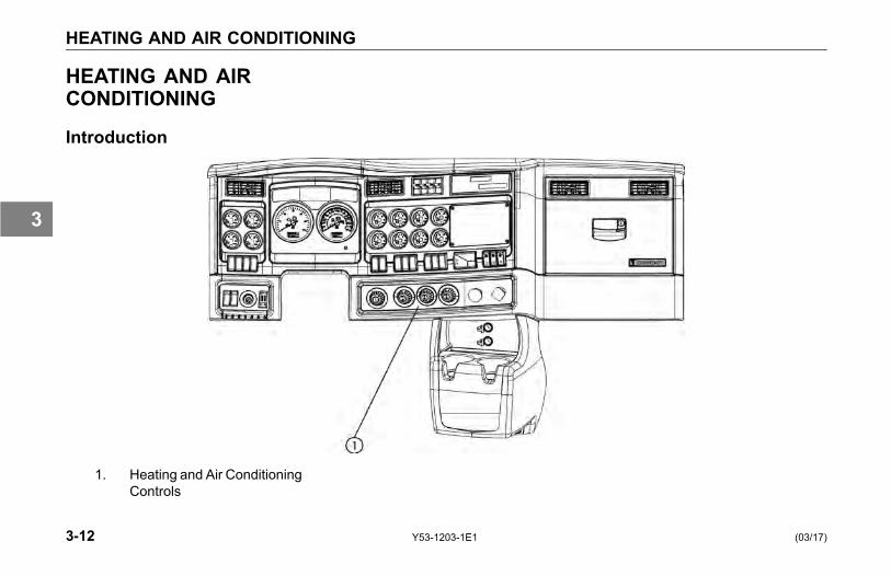
HEATING AND AIR CONDITIONING
HEATING AND AIRCONDITIONING
Introduction
1. Heating and Air ConditioningControls
3-12 Y53-1203-1E1 (03/17)
3
HEATING AND AIR CONDITIONING
The cab heater and A/C controls arelocated together in the center of thedash just to the right of the steeringcolumn. Additionally, the sleepercompartment may also contain aseparate heater and A/C controlslocated on the driver’s side sleepercabinet. Each control maintainsseparate temperature settings.
Precautions
WARNING!Do not drive with visibility reducedby fog, condensation, or frost on thewindshield. Your view may be ob-scured, which may result in personalinjury, death, equipment or propertydamage. For clear visibility and safedriving it is extremely important foryou to follow the instructions per-taining to the function and use ofthe ventilation/heating and defog-ging/defrosting system. If in doubt,consult your dealer. Maximum heat-ing output and fast defrosting can beobtained only after the engine hasreached operating temperature.
WARNING!The air conditioning system is un-der pressure. If not serviced prop-erly, it could explode and may resultin personal injury, death or propertydamage to your vehicle. Any servic-ing that requires depressurizing andrecharging the air conditioning sys-tem must be conducted by a quali-fied technician with the right facilitiesto do the job.
WARNING!Excessive heat may cause the pres-surized components of the air con-ditioning system to explode. Neverweld, solder, steam clean, or usea blow torch near any part of theair conditioning system. Failure tocomply may result in personal injury,death, equipment or property dam-age.
(03/17) Y53-1203-1E1 3-13
3
HEATING AND AIR CONDITIONING
• If a refrigerant leak develops inthe presence of excessive heator an open flame, hazardousgases may be generated.These gases may causeunconsciousness or death.If you become aware of arefrigerant leak on your vehiclehave your system servicedimmediately and observe thefollowing precautions:
° Stay away from the hotengine until the exhaustmanifold has cooled.
° Do not permit any openflame in the area. Even amatch or a cigarette lightermay generate a hazardousquantity of poisonous gas.
° Do not smoke in the area.Inhaling gaseous refrigerantthrough a cigarette maycause violent illness.
WARNING!Exhaust fumes from the enginecontain carbon monoxide, a col-orless and odorless gas. Do notbreathe the engine exhaust gas.A poorly maintained, damaged orcorroded exhaust system can allowcarbon monoxide to enter the cabor sleeper. Entry of carbon monox-ide into the cab or sleeper is alsopossible from other vehicles nearby.Failure to properly maintain your ve-hicle could cause carbon monoxideto enter the cab or sleeper, resultingin illness or death.
WARNING!Never idle your vehicle for prolongedperiods of time if you sense that ex-haust fumes are entering the cabor sleeper. Investigate the causeof the fumes and correct it as soonas possible. If the vehicle must bedriven under these conditions, driveonly with the windows open. Failureto repair the source of the exhaustfumes may result in personal injury,death, equipment or property dam-age.
NOTEKeep the engine exhaust systemand the vehicles cab/sleeper venti-lation system properly maintained.
It is recommended that the vehiclesexhaust system and cab/sleeper beinspected:
3-14 Y53-1203-1E1 (03/17)
3
HEATING AND AIR CONDITIONING
• By a competent technician every15,000 miles
• Whenever a change is noticed inthe sound of the exhaust system
• Whenever the exhaust system,underbody, or cab or sleeper isdamaged
NOTETo allow for proper operation of thevehicle ventilation system, keep theinlet grille at the base of the wind-shield clear of snow, ice, leaves andother obstructions at all times.
CAUTIONDo not stay in the vehicle with theengine running or idling for morethan 10 minutes with the vehicle'sHeater and A/C ventilation systemin RECIRC or at LOW FAN SPEED.Even with the ventilation system on,running the engine while parked orstopped for prolonged periods oftime is not recommended.
When idling for short periods of time:
• Set the heating or cooling systemto Heat or A/C
• Set the fan to Medium or Highspeed
• Set the controls to FRESH AIR
NOTEIf you are required to idle your ve-hicle for long periods of time, installan auxiliary heater or automatic idlecontrol. These auxiliary devices canreduce fuel consumption and saveyou money.
NOTEIf you are parked next to idling ve-hicles, move your vehicle or do notstay in your vehicle for prolonged pe-riods of time.
(03/17) Y53-1203-1E1 3-15
3
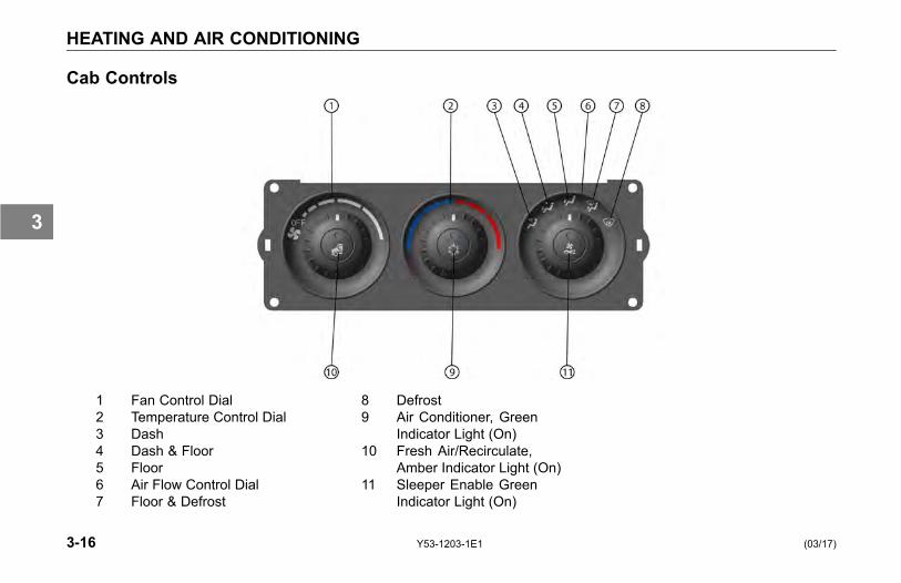
HEATING AND AIR CONDITIONING
Cab Controls
1 Fan Control Dial2 Temperature Control Dial3 Dash4 Dash & Floor5 Floor6 Air Flow Control Dial7 Floor & Defrost
8 Defrost9 Air Conditioner, Green
Indicator Light (On)10 Fresh Air/Recirculate,
Amber Indicator Light (On)11 Sleeper Enable Green
Indicator Light (On)
3-16 Y53-1203-1E1 (03/17)
3

HEATING AND AIR CONDITIONING
What Each Control Does
Fan Control Dial
Turning this dial clockwise from the OFFposition turns the fan ON and increasesthe fan speed.
Air Flow Control DialThis dial directs the air flow through 5primary sets of vents:
Dash Vents
Dash and Floor Vents
Floor Vents
Floor and *Defrost Vents
*Defrost Vents
*Fresh air and air conditioning areautomatically turned ON. As the dial isturned away from a primary position, thesystem directs an increasing amount of airflow towards the next primary position.
Temperature Control Dial
Turn this dial clockwise for heat,counterclockwise for cool.
Air Conditioner Switch
This switch turns the air conditioner Onand Off.
NOTEFan Control Dial must also be in theON position for A/C to be on.
Sleeper Enable Switch
This switch turns ON and OFF the sleepercontrol panel. Green light in center of dialcomes on when switch is enabled.
NOTEOn the Cab Control Unit, the SleeperEnable Switch must be pressedto turn ON power to the SleeperControl Unit. If air conditioning isrequested in the sleeper, the A/CSwitch on the Cab Control Unit andthe fan in the Cab Heater and A/CUnit will be turned ON low (if it wasOFF), automatically.
Fresh Air/Recirculation Switch
This switch controls the source of the airflowing into the heater and air conditionerunit.
Fresh Air mode = Air comes fromoutside the cab.
Recirculation mode = Air comesfrom inside the cab.
(03/17) Y53-1203-1E1 3-17
3
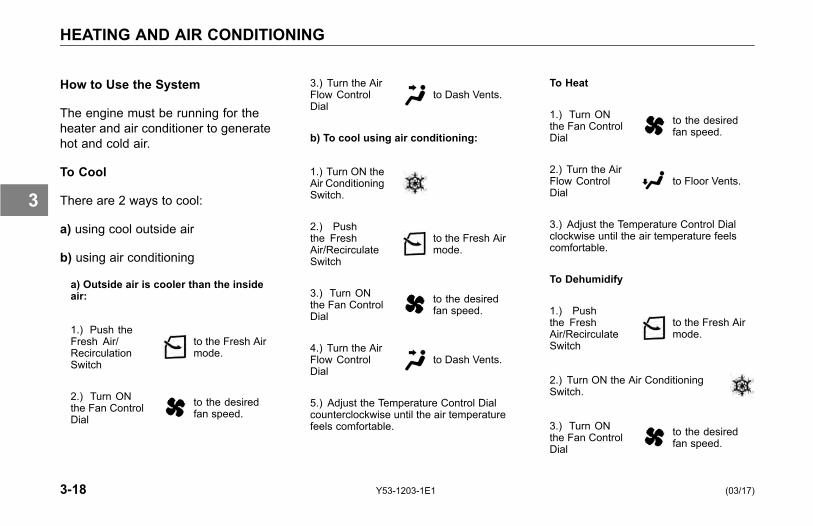
HEATING AND AIR CONDITIONING
How to Use the System
The engine must be running for theheater and air conditioner to generatehot and cold air.
To Cool
There are 2 ways to cool:
a) using cool outside air
b) using air conditioning
a) Outside air is cooler than the insideair:
1.) Push theFresh Air/RecirculationSwitch
to the Fresh Airmode.
2.) Turn ONthe Fan ControlDial
to the desiredfan speed.
3.) Turn the AirFlow ControlDial
to Dash Vents.
b) To cool using air conditioning:
1.) Turn ON theAir ConditioningSwitch.
2.) Pushthe FreshAir/RecirculateSwitch
to the Fresh Airmode.
3.) Turn ONthe Fan ControlDial
to the desiredfan speed.
4.) Turn the AirFlow ControlDial
to Dash Vents.
5.) Adjust the Temperature Control Dialcounterclockwise until the air temperaturefeels comfortable.
To Heat
1.) Turn ONthe Fan ControlDial
to the desiredfan speed.
2.) Turn the AirFlow ControlDial
to Floor Vents.
3.) Adjust the Temperature Control Dialclockwise until the air temperature feelscomfortable.
To Dehumidify
1.) Pushthe FreshAir/RecirculateSwitch
to the Fresh Airmode.
2.) Turn ON the Air ConditioningSwitch.
3.) Turn ONthe Fan ControlDial
to the desiredfan speed.
3-18 Y53-1203-1E1 (03/17)
3

HEATING AND AIR CONDITIONING
4.) Adjust the Temperature Control Dialuntil the air temperature feels comfortable.
The air conditioner removes moisturefrom the air while the heater heats theair.
To Defog and Defrost the Windshield
1.) Turn theFan ControlDial
clockwise tothe highest fanspeed.
2.) Turn the AirFlow ControlDial
to DefrostVents.
Fresh air and air conditioning areautomatically turned ON.
3.) Adjust the Temperature Control Dialclockwise to full heat.
CAUTIONDuring extreme cold weather, do notblow hot defroster air onto cold wind-shields. This could crack the glass.Turn the Air Flow Control Dial to De-frost and adjust the fan speed ac-cordingly while the engine warms. Ifthe engine is already warm, movethe Temperature Control Dial to cool,then gradually increase the temper-ature when you see that the wind-shield is starting to warm up. Failureto comply may result in equipmentdamage.
Sleeper Heater - A/CControls (option)
NOTEOn the Cab Control Unit, the SleeperEnable Switch must be pressed toturn ON power to the Sleeper Con-trol Unit. In addition, if air condition-ing is requested in the sleeper, theAir Conditioner Switch on the CabControl Unit will be turned ON andthe fan in the Cab Heater and AirConditioning Unit will be turned ONlow (if it was OFF), automatically.
Modular Sleeper Controls
(03/17) Y53-1203-1E1 3-19
3

HEATING AND AIR CONDITIONING
Aerocab & Studio Sleeper Controls
Fan Control (1)
Turning this dial controls fan speed.
Heat & A/C Control (2) (Aerocab &Studio):
Allows you to select between, MaxHeat, Max A/C, and Auto Heat - A/C.
• Max Heat: Fully opens the valvethat allows hot engine coolant toflow through the heater core.
• Max A/C: Completely closes theengine coolant valve.
• Auto Heat - A/C: Works togetherwith the Temperature Control(3) to maintain the temperatureautomatically.
Heat & A/C Control (2) (Modular):
Allows you to select between Heat orA/C.
• Heat: The fan cycles on/off toregulate temperature based on theTemperature Control (3) setting.
• A/C: A refrigerant solenoid valvecycles open/closed to regulatethe temperature based on theTemperature Control (3) setting.
Temperature Control (3):
The temperature for the sleeper iscontrolled automatically.
Set the Heat & A/C Control to:
• AutoHeat - A/C (for Aerocabs &Studios)
• Heat or A/C (for Modulars)
Adjust the Temperature Control anda sensor will then control the sleepertemperature. The Temperature Controlis not keyed to specific temperatures.Turning counterclockwise meanscooler than it is now. Clockwise meanswarmer than it is now. Once thedesired temperature is reached, thesystem will maintain it automatically.
3-20 Y53-1203-1E1 (03/17)
3
HEATING AND AIR CONDITIONING
NOTEThe sensor is located on the sleeperheater - A/C control panel and mea-sures the sleeper air temperatureat the panel. There will be a timedelay between Temperature Controladjustment and sleeper air tempera-ture change. Also, be careful of anyheat source which could affect theair temperature by the sensor. Avoidhanging items (e.g. shirt, jacket,etc.) which could block the air flowto the sensor.
(03/17) Y53-1203-1E1 3-21
3
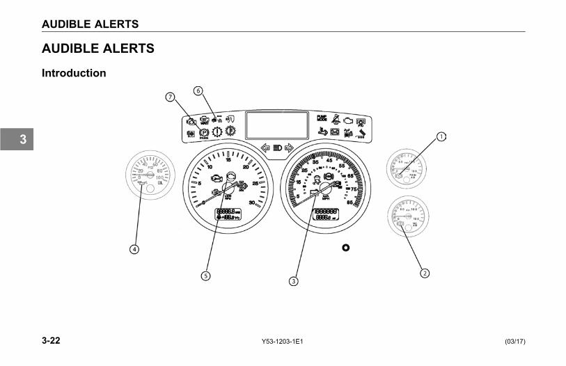
AUDIBLE ALERTS
AUDIBLE ALERTS
Introduction
3-22 Y53-1203-1E1 (03/17)
3

AUDIBLE ALERTS
Your vehicle's dash andinstrumentation uses variousmethods to indicate to you the statusof various systems, or that one ormore of your vehicle's systems maybe malfunctioning. The methodto communicate or alert you of aparticular condition is by:
• Audible alarm tone
• Audible warning tone
• Indicator light(s)
In some cases, you may have both analarm or warning tone accompanied byan indicator light(s).
WARNING!Do not ignore any type of tone orlights. These signals tell you thatsomething is malfunctioning on yourvehicle and provide you an indi-cation of what system is affected.It could be a failure of an impor-tant system, such as the brakes,which could lead to an accident andmay result in personal injury, death,equipment or property damage.
Please remember that each Kenworthis custom made. Your instrumentpanel may not look exactly like the onein the illustration.
(03/17) Y53-1203-1E1 3-23
3
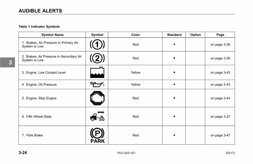
AUDIBLE ALERTS
Table 1 Indicator Symbols
Symbol Name Symbol Color Standard Option Page
1. Brakes, Air Pressure in Primary AirSystem is Low Red ● on page 3-26
2. Brakes, Air Pressure in Secondary AirSystem is Low Red ● on page 3-26
3. Engine, Low Coolant Level Yellow ● on page 3-43
4. Engine, Oil Pressure Yellow ● on page 3-43
5. Engine, Stop Engine Red ● on page 3-44
6. Fifth Wheel Slide Red ● on page 3-27
7. Park Brake Red ● on page 3-47
3-24 Y53-1203-1E1 (03/17)
3
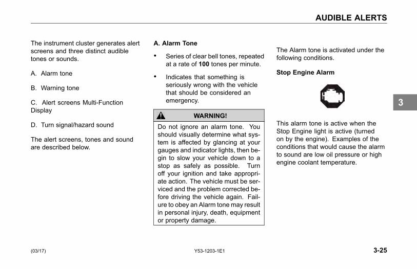
AUDIBLE ALERTS
The instrument cluster generates alertscreens and three distinct audibletones or sounds.
A. Alarm tone
B. Warning tone
C. Alert screens Multi-FunctionDisplay
D. Turn signal/hazard sound
The alert screens, tones and soundare described below.
A. Alarm Tone
• Series of clear bell tones, repeatedat a rate of 100 tones per minute.
• Indicates that something isseriously wrong with the vehiclethat should be considered anemergency.
WARNING!Do not ignore an alarm tone. Youshould visually determine what sys-tem is affected by glancing at yourgauges and indicator lights, then be-gin to slow your vehicle down to astop as safely as possible. Turnoff your ignition and take appropri-ate action. The vehicle must be ser-viced and the problem corrected be-fore driving the vehicle again. Fail-ure to obey an Alarm tonemay resultin personal injury, death, equipmentor property damage.
The Alarm tone is activated under thefollowing conditions.
Stop Engine Alarm
This alarm tone is active when theStop Engine light is active (turnedon by the engine). Examples of theconditions that would cause the alarmto sound are low oil pressure or highengine coolant temperature.
(03/17) Y53-1203-1E1 3-25
3

AUDIBLE ALERTS
Primary or Secondary Low AirWarning Alarm
This alarm tone is active when eitherthe Primary or Secondary Low AirWarning lamp is active and the engineRPM is above 300. This occurs whenthe primary or secondary air pressuredrops below 65 psi (448 kPa), andstays active until it increases above66.5 psi (458 kPa). The tone is onlyactive when the engine is running(RPM above 300).
Engine Oil Pressure Alarm
This alarm tone is active when theEngine Oil Pressure light is active(turned on by the engine).
Park Brake Alarm
With the park brake not set and thedoor open, the Alarm tone is activatedfor approximately 4.5 minutes and thepark brake warning light will blink.
B. Warning tone (similar to theAlarm tone)
• Series of clear bell tones, repeatedat a rate of 60 tones per minute.
• Sounds when a problem exists,but the vehicle can still be safelydriven. Service the vehicle tocorrect the problem but thesituation should not be consideredan emergency.
CAUTIONIf a warning tone sounds, determinethe system affected by glancing atyour indicator lights. The warningtone indicates a problem exists, butthe vehicle can still be safely driven.Service the vehicle at your earliestconvenience to correct the problem,but the situation should not be con-sidered an emergency.
The Warning tone is activated underthe following conditions.
3-26 Y53-1203-1E1 (03/17)
3
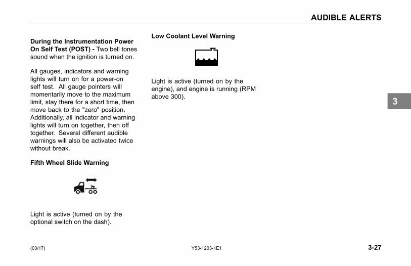
AUDIBLE ALERTS
During the Instrumentation PowerOn Self Test (POST) - Two bell tonessound when the ignition is turned on.
All gauges, indicators and warninglights will turn on for a power-onself test. All gauge pointers willmomentarily move to the maximumlimit, stay there for a short time, thenmove back to the "zero" position.Additionally, all indicator and warninglights will turn on together, then offtogether. Several different audiblewarnings will also be activated twicewithout break.
Fifth Wheel Slide Warning
Light is active (turned on by theoptional switch on the dash).
Low Coolant Level Warning
Light is active (turned on by theengine), and engine is running (RPMabove 300).
(03/17) Y53-1203-1E1 3-27
3

INDICATORS
INDICATORS
Introduction
Numbered items in illustration are standard or common indicators.
3-28 Y53-1203-1E1 (03/17)
3
INDICATORS
NOTEYour vehicle includes both standardand optional gauges in the instru-ment cluster display. Some optionalwarning light indicators will be inop-erable unless that option was speci-fied with the vehicle.
Your vehicle's dash andinstrumentation uses variousmethods to indicate to you the statusof various systems, or that one ormore of your vehicles systems maybe malfunctioning. The methodto communicate or alert you of aparticular condition is by:
• Audible alarm tone
• Audible warning tone
• Indicator light(s)
In some cases, you may have both analarm or warning tone accompanied byan indicator light(s).
WARNING!Do not ignore any type of tone orlights. These signals tell you thatsomething is malfunctioning on yourvehicle and provide you an indi-cation of what system is affected.It could be a failure of an impor-tant system, such as the brakes,which could lead to an accident andmay result in personal injury, death,equipment or property damage.
Please remember that each Kenworthis custom made. Your instrumentpanel may not look exactly like the onein the illustration.
(03/17) Y53-1203-1E1 3-29
3
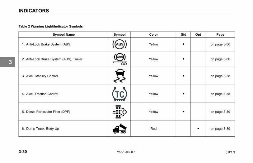
INDICATORS
Table 2 Warning Light/Indicator Symbols
Symbol Name Symbol Color Std Opt Page
1. Anti-Lock Brake System (ABS) Yellow ● on page 3-36
2. Anti-Lock Brake System (ABS), Trailer Yellow ● on page 3-36
3. Axle, Stability Control Yellow ● on page 3-38
4. Axle, Traction Control Yellow ● on page 3-38
5. Diesel Particulate Filter (DPF) Yellow ● on page 3-39
6. Dump Truck, Body Up Red ● on page 3-39
3-30 Y53-1203-1E1 (03/17)
3
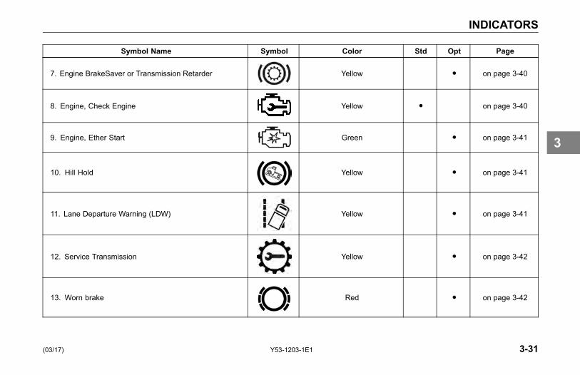
INDICATORS
Symbol Name Symbol Color Std Opt Page
7. Engine BrakeSaver or Transmission Retarder Yellow ● on page 3-40
8. Engine, Check Engine Yellow ● on page 3-40
9. Engine, Ether Start Green ● on page 3-41
10. Hill Hold Yellow ● on page 3-41
11. Lane Departure Warning (LDW) Yellow ● on page 3-41
12. Service Transmission Yellow ● on page 3-42
13. Worn brake Red ● on page 3-42
(03/17) Y53-1203-1E1 3-31
3
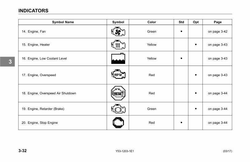
INDICATORS
Symbol Name Symbol Color Std Opt Page
14. Engine, Fan Green ● on page 3-42
15. Engine, Heater Yellow ● on page 3-43
16. Engine, Low Coolant Level Yellow ● on page 3-43
17. Engine, Overspeed Red ● on page 3-43
18. Engine, Overspeed Air Shutdown Red ● on page 3-44
19. Engine, Retarder (Brake) Green ● on page 3-44
20. Engine, Stop Engine Red ● on page 3-44
3-32 Y53-1203-1E1 (03/17)
3
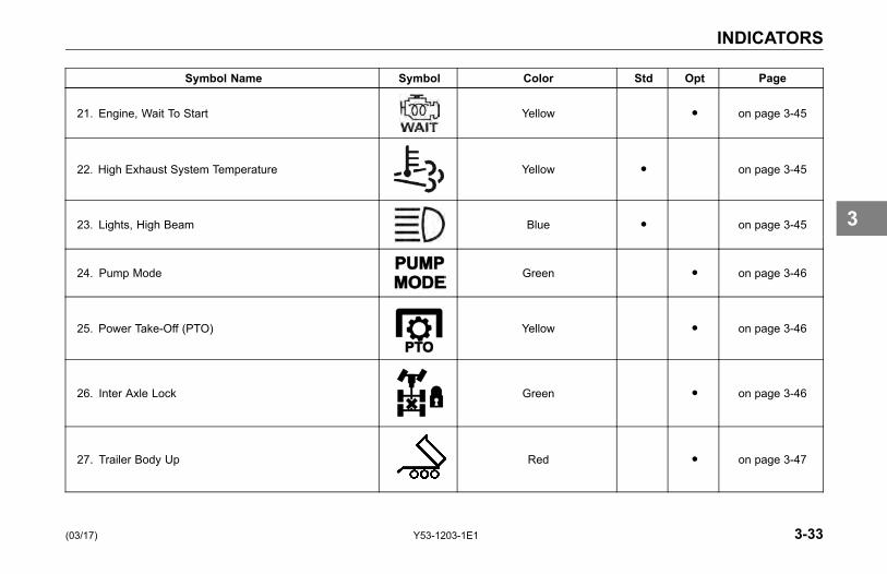
INDICATORS
Symbol Name Symbol Color Std Opt Page
21. Engine, Wait To Start Yellow ● on page 3-45
22. High Exhaust System Temperature Yellow ● on page 3-45
23. Lights, High Beam Blue ● on page 3-45
24. Pump Mode Green ● on page 3-46
25. Power Take-Off (PTO) Yellow ● on page 3-46
26. Inter Axle Lock Green ● on page 3-46
27. Trailer Body Up Red ● on page 3-47
(03/17) Y53-1203-1E1 3-33
3
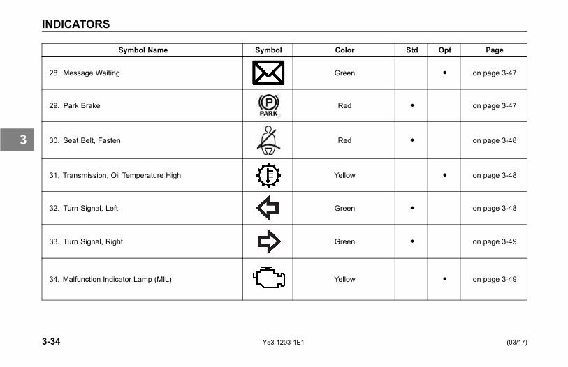
INDICATORS
Symbol Name Symbol Color Std Opt Page
28. Message Waiting Green ● on page 3-47
29. Park Brake Red ● on page 3-47
30. Seat Belt, Fasten Red ● on page 3-48
31. Transmission, Oil Temperature High Yellow ● on page 3-48
32. Turn Signal, Left Green ● on page 3-48
33. Turn Signal, Right Green ● on page 3-49
34. Malfunction Indicator Lamp (MIL) Yellow ● on page 3-49
3-34 Y53-1203-1E1 (03/17)
3
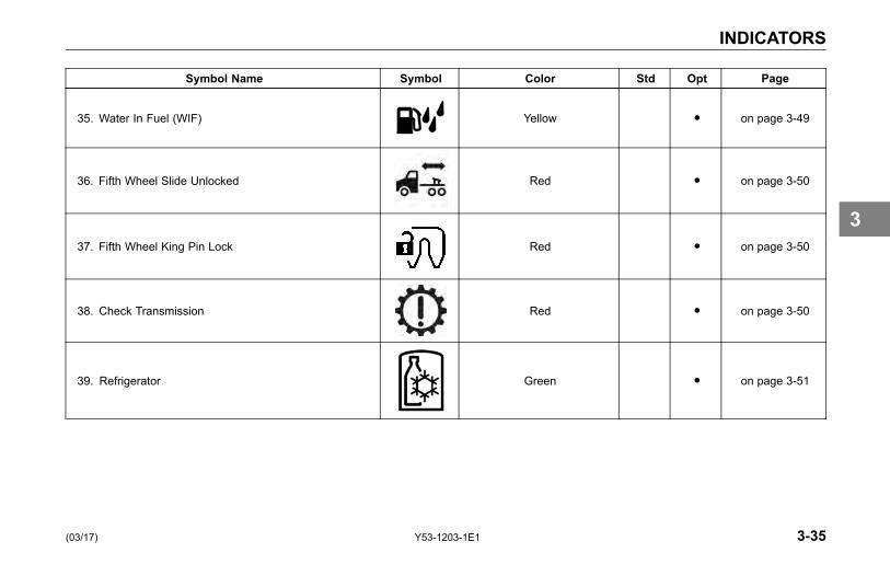
INDICATORS
Symbol Name Symbol Color Std Opt Page
35. Water In Fuel (WIF) Yellow ● on page 3-49
36. Fifth Wheel Slide Unlocked Red ● on page 3-50
37. Fifth Wheel King Pin Lock Red ● on page 3-50
38. Check Transmission Red ● on page 3-50
39. Refrigerator Green ● on page 3-51
(03/17) Y53-1203-1E1 3-35
3
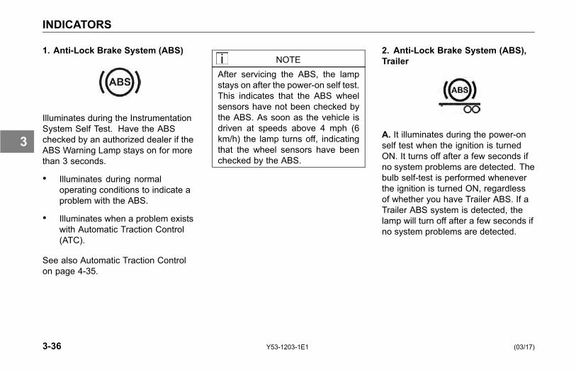
INDICATORS
1. Anti-Lock Brake System (ABS)
Illuminates during the InstrumentationSystem Self Test. Have the ABSchecked by an authorized dealer if theABS Warning Lamp stays on for morethan 3 seconds.
• Illuminates during normaloperating conditions to indicate aproblem with the ABS.
• Illuminates when a problem existswith Automatic Traction Control(ATC).
See also Automatic Traction Controlon page 4-35.
NOTEAfter servicing the ABS, the lampstays on after the power-on self test.This indicates that the ABS wheelsensors have not been checked bythe ABS. As soon as the vehicle isdriven at speeds above 4 mph (6km/h) the lamp turns off, indicatingthat the wheel sensors have beenchecked by the ABS.
2. Anti-Lock Brake System (ABS),Trailer
A. It illuminates during the power-onself test when the ignition is turnedON. It turns off after a few seconds ifno system problems are detected. Thebulb self-test is performed wheneverthe ignition is turned ON, regardlessof whether you have Trailer ABS. If aTrailer ABS system is detected, thelamp will turn off after a few seconds ifno system problems are detected.
3-36 Y53-1203-1E1 (03/17)
3

INDICATORS
CAUTIONIf the Trailer ABS Warning Lampdoes not turn on during the power-onself test, there may be a problemwith the light or wiring. You shouldhave this checked as soon as pos-sible.
B. If it turns on at any other time,it is indicating that a problem existswith the Power Line Communication(PLC) trailer ABS. This should bechecked by a Kenworth dealer as soonas possible. (Refer to "Trailer ABS"in the Operator's Manual for moreinformation.)
C. If your tractor and trailer havethe "Special Trailer ABS (WithoutPLC) Option", (Refer to "SpecialTrailer ABS (Without PLC) Option"in the Operator's Manual for moreinformation.) this lamp will turn onwhen the trailer ABS has a systemproblem. This should be checked by a
Kenworth dealer as soon as possible.The Trailer ABS Warning Lamp will notturn on for the power-on self test whenconnected to these types of trailers.
CAUTIONIf the Trailer ABS Warning Lampdoes not turn on during the power-onself test there may be a problem withthe light or wiring. You should havethis checked as soon as possible.
NOTETractors/Trucks and trailers built af-ter 3/1/01 must be able to turn on anIn-Cab Trailer ABS Warning Lamp(per U.S. FMVSS121). The industrychose PLC as the standard methodto turn it on. (Refer to "Trailer ABS"in theOperator's Manual for more in-formation.)
NOTEThe Trailer ABS Warning Lampwill not turn on when connected totrailers with ABS (but without PLC)powered through the primary 7-waytrailer light line. Use the lamp on thedriver's side of the trailer to identifytrailer ABS problems.
NOTEFor doubles or triples, the lamp doesnot distinguish between trailers. AnABS problem in any of the trailerswill activate the Trailer ABSWarningLamp.
(03/17) Y53-1203-1E1 3-37
3
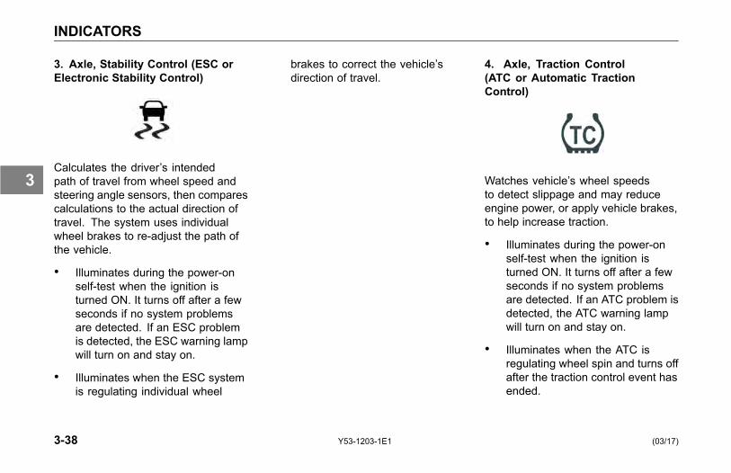
INDICATORS
3. Axle, Stability Control (ESC orElectronic Stability Control)
Calculates the driver’s intendedpath of travel from wheel speed andsteering angle sensors, then comparescalculations to the actual direction oftravel. The system uses individualwheel brakes to re-adjust the path ofthe vehicle.
• Illuminates during the power-onself-test when the ignition isturned ON. It turns off after a fewseconds if no system problemsare detected. If an ESC problemis detected, the ESC warning lampwill turn on and stay on.
• Illuminates when the ESC systemis regulating individual wheel
brakes to correct the vehicle’sdirection of travel.
4. Axle, Traction Control(ATC or Automatic TractionControl)
Watches vehicle’s wheel speedsto detect slippage and may reduceengine power, or apply vehicle brakes,to help increase traction.
• Illuminates during the power-onself-test when the ignition isturned ON. It turns off after a fewseconds if no system problemsare detected. If an ATC problem isdetected, the ATC warning lampwill turn on and stay on.
• Illuminates when the ATC isregulating wheel spin and turns offafter the traction control event hasended.
3-38 Y53-1203-1E1 (03/17)
3

INDICATORS
• Flashes continuously when theATC/Deep Snow & Mud switchis turned on, indicating that thisfeature is active.
5. Diesel Particulate Filter (DPF)
Illuminates when diesel particulatefilter needs regeneration (controlledby Engine Control Module (ECM)).This warning lamp will illuminateeven if the regeneration operationis disabled. (Refer to the EngineManufacturer's Operator Manual andthe PACCAR Engine After-treatmentControl Operator Manual for additionalinformation.)
NOTEOnly for engines equipped withemissions aftertreatment.
6. Dump Truck, Body Up
Illuminates when Truck Dump Body isup.
(03/17) Y53-1203-1E1 3-39
3

INDICATORS
7. Engine BrakeSaver orTransmission Retarder
Illuminates when BrakeSaver (exportonly) or Transmission Retarder isactive.
8. Engine, Check Engine
Illuminates when a problem exists, butthe vehicle can still be safely driven.Vehicle should be serviced to correctthe problem, but the situation shouldnot be considered an emergency.
The Check Engine lamp will activatefor several reasons. These includebut are not limited to Water in Fueland No-Idle Shutdown alert screensand the High Exhaust Temperature,Diesel Particulate Filter (DPF), DieselExhaust Fluid (DEF) warning lights.You may need to refer to your EngineOperator's Manual for additionalinformation.
NOTEOnly for engines equipped withemissions aftertreatment.
3-40 Y53-1203-1E1 (03/17)
3
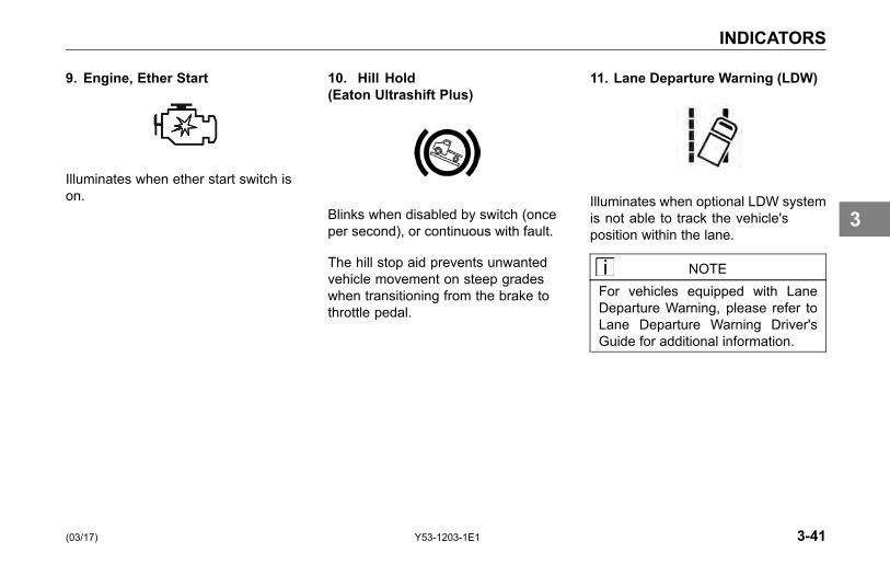
INDICATORS
9. Engine, Ether Start
Illuminates when ether start switch ison.
10. Hill Hold(Eaton Ultrashift Plus)
Blinks when disabled by switch (onceper second), or continuous with fault.
The hill stop aid prevents unwantedvehicle movement on steep gradeswhen transitioning from the brake tothrottle pedal.
11. Lane Departure Warning (LDW)
Illuminates when optional LDW systemis not able to track the vehicle'sposition within the lane.
NOTEFor vehicles equipped with LaneDeparture Warning, please refer toLane Departure Warning Driver'sGuide for additional information.
(03/17) Y53-1203-1E1 3-41
3

INDICATORS
12. Service Transmission
Illuminates when Allison 1000/2000transmission requires service.
13. Worn Brake
Illuminates when brake pads onoptional Brake Warning Systemrequire replacement.
14. Engine, Fan
Illuminates when fan is active.
3-42 Y53-1203-1E1 (03/17)
3

INDICATORS
15. Engine, Heater
Illuminates when Engine Heater switchis on.
16. Engine, Low Coolant Level
Illuminates and an audible warningtone will sound when coolant level inthe radiator is critically low.
CAUTIONThe vehicle must be serviced to cor-rect the problem, but the situationshould not be considered an emer-gency.
17. Engine, Overspeed
Illuminates when engine RPM isexceeded (Allison Transmissions).
(03/17) Y53-1203-1E1 3-43
3

INDICATORS
18. Engine, Overspeed AirShutdown
Illuminates when the EngineOverspeed Air Shutdown system isactivated.
19. Engine, Retarder (Brake)
Illuminates when the engine retarder(compression brake), BrakeSaver(export only), or exhaust brake isswitch is on (Smartwheel only).
20. Engine, Stop Engine
Illuminates and an audible alarm tonewill sound when a major engine systemproblem exists.
WARNING!This should be considered an emer-gency. You should stop the vehicleas safely as possible and turn OFFthe ignition. The vehicle must beserviced and the problem correctedbefore driving again. Failure to doso may cause severe engine dam-age or cause an accident which mayresult in personal injury or death.
3-44 Y53-1203-1E1 (03/17)
3

INDICATORS
21. Engine, Wait to Start
Illuminates when engine grid heateris on. (PACCAR PX-6, PX-8, andCummins ISL engines)
22. High Exhaust SystemTemperature
Illuminates when exhausttemperature is high (controlled byEngine Control Module (ECM)). (Referto the Engine Manufacturer's OperatorManual and the PACCAR EngineAfter-treatment Control OperatorManual for additional information.)
23. Lights, High Beam
Illuminates when the high beams areon.
The high beam indicator will flash anda tone will sound to indicate that thehead lamps are left on when: the headlamp switch is ON, the driver's door isopen, AND the key switch is OFF.
(03/17) Y53-1203-1E1 3-45
3
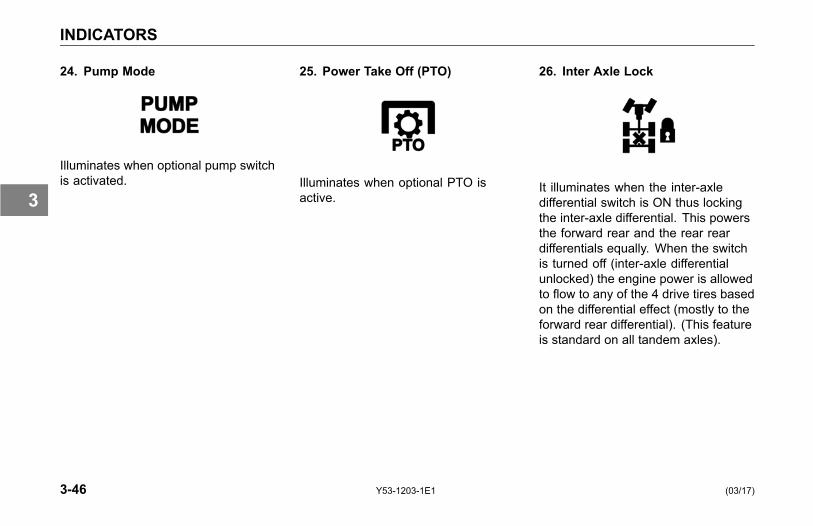
INDICATORS
24. Pump Mode
Illuminates when optional pump switchis activated.
25. Power Take Off (PTO)
Illuminates when optional PTO isactive.
26. Inter Axle Lock
It illuminates when the inter-axledifferential switch is ON thus lockingthe inter-axle differential. This powersthe forward rear and the rear reardifferentials equally. When the switchis turned off (inter-axle differentialunlocked) the engine power is allowedto flow to any of the 4 drive tires basedon the differential effect (mostly to theforward rear differential). (This featureis standard on all tandem axles).
3-46 Y53-1203-1E1 (03/17)
3

INDICATORS
27. Trailer Body Up
Illuminates when optional trailer bodyup switch is activated.
28. Message Waiting
Illuminates with telematic equippedmessaging.
29. Park Brake
Illuminates when parking brakes areapplied.
The Park Brake lamp will flash and thewarning tone will sound anytime thePark Brake is not set and the driver'sdoor is open.
(03/17) Y53-1203-1E1 3-47
3
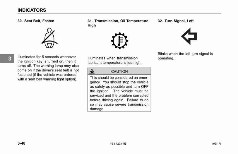
INDICATORS
30. Seat Belt, Fasten
Illuminates for 5 seconds wheneverthe ignition key is turned on, then itturns off. The warning lamp may alsocome on if the driver's seat belt is notfastened (if the vehicle was orderedwith a seat belt warning light option).
31. Transmission, Oil TemperatureHigh
Illuminates when transmissionlubricant temperature is too high.
CAUTIONThis should be considered an emer-gency. You should stop the vehicleas safely as possible and turn OFFthe ignition. The vehicle must beserviced and the problem correctedbefore driving again. Failure to doso may cause severe transmissiondamage.
32. Turn Signal, Left
Blinks when the left turn signal isoperating.
3-48 Y53-1203-1E1 (03/17)
3
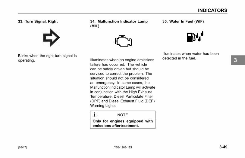
INDICATORS
33. Turn Signal, Right
Blinks when the right turn signal isoperating.
34. Malfunction Indicator Lamp(MIL)
Illuminates when an engine emissionsfailure has occurred. The vehiclecan be safely driven but should beserviced to correct the problem. Thesituation should not be consideredan emergency. In some cases, theMalfunction Indicator Lamp will activatein conjunction with the High ExhaustTemperature, Diesel Particulate Filter(DPF) and Diesel Exhaust Fluid (DEF)Warning Lights.
NOTEOnly for engines equipped withemissions aftertreatment.
35. Water In Fuel (WIF)
Illuminates when water has beendetected in the fuel.
(03/17) Y53-1203-1E1 3-49
3
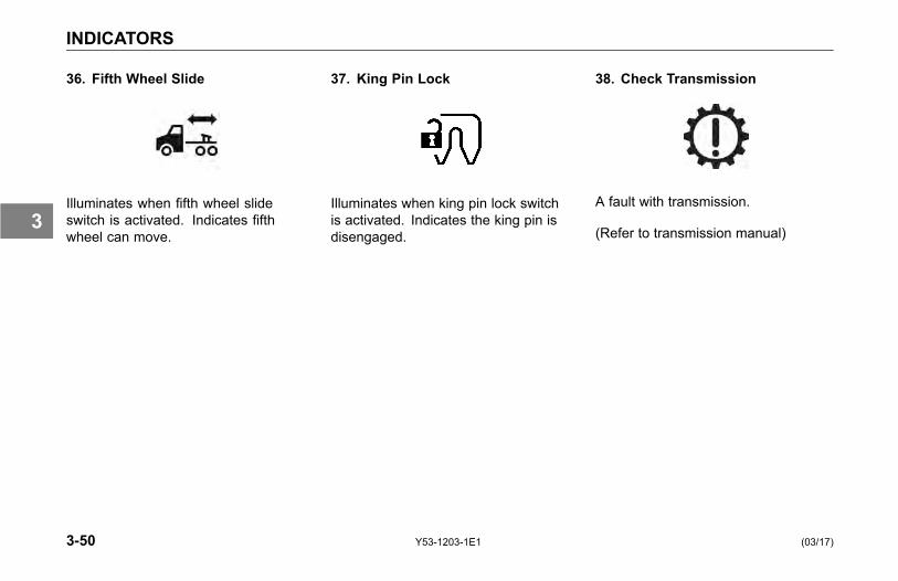
INDICATORS
36. Fifth Wheel Slide
Illuminates when fifth wheel slideswitch is activated. Indicates fifthwheel can move.
37. King Pin Lock
Illuminates when king pin lock switchis activated. Indicates the king pin isdisengaged.
38. Check Transmission
A fault with transmission.
(Refer to transmission manual)
3-50 Y53-1203-1E1 (03/17)
3

INDICATORS
39. Refrigerator
Indicates when the refrigerator is on.
(03/17) Y53-1203-1E1 3-51
3
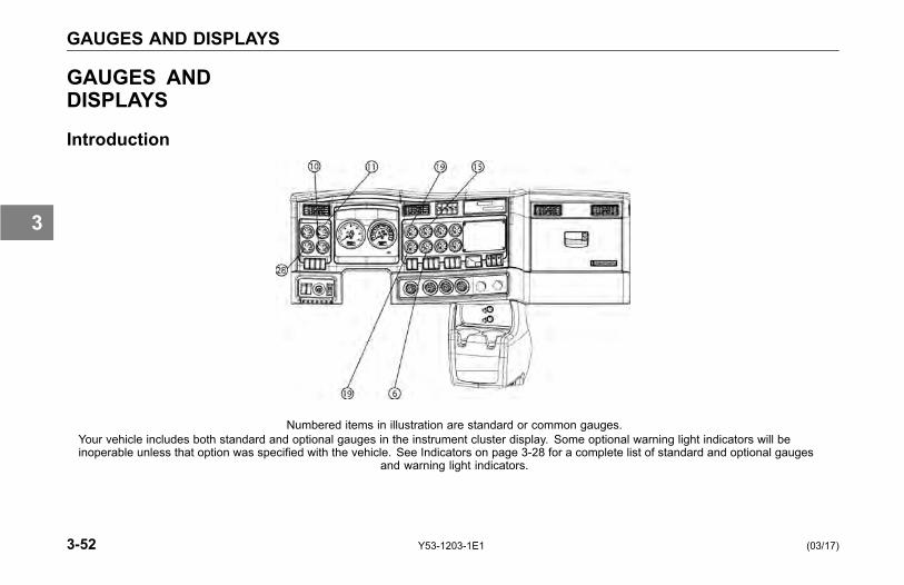
GAUGES AND DISPLAYS
GAUGES ANDDISPLAYS
Introduction
Numbered items in illustration are standard or common gauges.Your vehicle includes both standard and optional gauges in the instrument cluster display. Some optional warning light indicators will beinoperable unless that option was specified with the vehicle. See Indicators on page 3-28 for a complete list of standard and optional gauges
and warning light indicators.
3-52 Y53-1203-1E1 (03/17)
3

GAUGES AND DISPLAYS
Gauges
Table 3 Gauges Symbol
Symbol Name Symbol Std Opt Page
1. Air Filter Restriction Pressure ● on page 3-59
2. Ammeter ● on page 3-59
3. Axle, Drive Oil Temperature
Front
Rear
Center(Tridem)
● on page 3-60
4. Axle, Pusher Air Pressure, #1, #2, #3 ● on page 3-61
5. Axle, Tag Air Pressure ● on page 3-61
6. Brake, Application Air Pressure ● on page 3-62
(03/17) Y53-1203-1E1 3-53
3
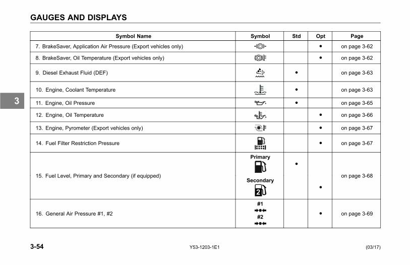
GAUGES AND DISPLAYS
Symbol Name Symbol Std Opt Page
7. BrakeSaver, Application Air Pressure (Export vehicles only) ● on page 3-62
8. BrakeSaver, Oil Temperature (Export vehicles only) ● on page 3-62
9. Diesel Exhaust Fluid (DEF) ● on page 3-63
10. Engine, Coolant Temperature ● on page 3-63
11. Engine, Oil Pressure ● on page 3-65
12. Engine, Oil Temperature ● on page 3-66
13. Engine, Pyrometer (Export vehicles only) ● on page 3-67
14. Fuel Filter Restriction Pressure ● on page 3-67
Primary●
15. Fuel Level, Primary and Secondary (if equipped)Secondary
●
on page 3-68
16. General Air Pressure #1, #2
#1
#2● on page 3-69
3-54 Y53-1203-1E1 (03/17)
3

GAUGES AND DISPLAYS
Symbol Name Symbol Std Opt Page
17. General Oil Temperature ● on page 3-70
18. Manifold Pressure (Turbo Boost) ● on page 3-70
19. Primary and Secondary Air Pressure
Primary
Secondary ● on page 3-70
20. Suspension Load Air Pressure, #1, #2
#1
#2● on page 3-72
21. Tractor Brake Application Air Pressure ● on page 3-73
22. Trailer Brake Application Air Pressure ● on page 3-73
23. Trailer Air Tank Air Pressure ● on page 3-74
24. Transfer Case Oil Temperature ● on page 3-74
25. Transmission Oil Temperature, Main ● on page 3-74
(03/17) Y53-1203-1E1 3-55
3
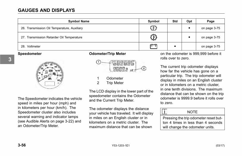
GAUGES AND DISPLAYS
Symbol Name Symbol Std Opt Page
26. Transmission Oil Temperature, Auxiliary ● on page 3-75
27. Transmission Retarder Oil Temperature ● on page 3-75
28. Voltmeter ● on page 3-75
Speedometer
The Speedometer indicates the vehiclespeed in miles per hour (mph) andin kilometers per hour (km/h). TheSpeedometer cluster also includesseveral warning and indicator lamps(see Audible Alerts on page 3-22) andan Odometer/Trip Meter.
Odometer/Trip Meter
1 Odometer2 Trip Meter
The LCD display in the lower part of thespeedometer contains the Odometerand the Current Trip Meter.
The odometer displays the distanceyour vehicle has traveled. It will displayin miles on an English cluster or inkilometers on a metric cluster. Themaximum distance that can be shown
on the odometer is 999,999 before itrolls over to zero.
The current trip odometer displayshow far the vehicle has gone on aparticular trip. The trip odometer willdisplay in miles on an English clusteror in kilometers on a metric cluster,in one tenth divisions. The maximumdistance that can be shown on the tripodometer is 9999.9 before it rolls overto zero.
NOTEPressing the trip odometer reset but-ton 4 times in less than 4 secondswill change the odometer units.
3-56 Y53-1203-1E1 (03/17)
3
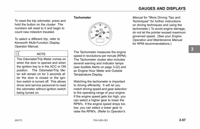
GAUGES AND DISPLAYS
To reset the trip odometer, press andhold the button on the cluster. Thenumbers will reset to 0 and begin tocount new miles/km traveled.
To select a different trip, refer toKenworth Multi-Function DisplayOperator Manual.
NOTEThe Odometer/Trip Meter comes onwhen the door is opened and whenthe ignition key is in the ACC or ONposition. The Odometer/Trip Me-ter will remain on for 3 seconds af-ter the door is closed or the igni-tion switch is turned off. This allowsdriver and service personnel to readthe odometer without ignition switchbeing turned on.
Tachometer
The Tachometer measures the enginespeed in revolutions per minute (RPM).The Tachometer cluster also includesseveral warning and indicator lamps(see Audible Alerts on page 3-22) andan Engine Hour Meter and OutsideTemperature Display.
Watching the tachometer is importantto driving efficiently. It will let youmatch driving speed and gear selectionto the operating range of your engine.If the engine speed gets too high, youcan select a higher gear to lower theRPM's. If the engine speed drops toolow, you can select a lower gear toraise the RPM's. (Refer to Operator's
Manual for "More Driving Tips andTechniques" for further instructionson driving techniques and using thetachometer.) To avoid engine damage,do not let the pointer exceed maximumgoverned speed. (See your EngineOperation and Maintenance Manualfor RPM recommendations.)
(03/17) Y53-1203-1E1 3-57
3
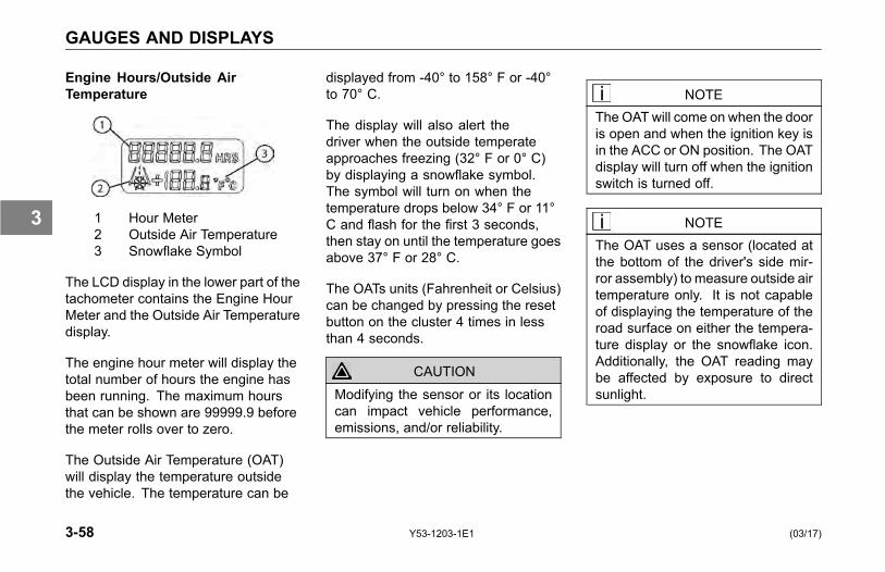
GAUGES AND DISPLAYS
Engine Hours/Outside AirTemperature
1 Hour Meter2 Outside Air Temperature3 Snowflake Symbol
The LCD display in the lower part of thetachometer contains the Engine HourMeter and the Outside Air Temperaturedisplay.
The engine hour meter will display thetotal number of hours the engine hasbeen running. The maximum hoursthat can be shown are 99999.9 beforethe meter rolls over to zero.
The Outside Air Temperature (OAT)will display the temperature outsidethe vehicle. The temperature can be
displayed from -40° to 158° F or -40°to 70° C.
The display will also alert thedriver when the outside temperateapproaches freezing (32° F or 0° C)by displaying a snowflake symbol.The symbol will turn on when thetemperature drops below 34° F or 11°C and flash for the first 3 seconds,then stay on until the temperature goesabove 37° F or 28° C.
The OATs units (Fahrenheit or Celsius)can be changed by pressing the resetbutton on the cluster 4 times in lessthan 4 seconds.
CAUTIONModifying the sensor or its locationcan impact vehicle performance,emissions, and/or reliability.
NOTEThe OAT will come on when the dooris open and when the ignition key isin the ACC or ON position. The OATdisplay will turn off when the ignitionswitch is turned off.
NOTEThe OAT uses a sensor (located atthe bottom of the driver's side mir-ror assembly) to measure outside airtemperature only. It is not capableof displaying the temperature of theroad surface on either the tempera-ture display or the snowflake icon.Additionally, the OAT reading maybe affected by exposure to directsunlight.
3-58 Y53-1203-1E1 (03/17)
3

GAUGES AND DISPLAYS
1. Air Filter Restriction Pressure
The Air Filter Restriction Pressuregauge indicates the condition of theengine air cleaner and is measured byinches of water (H2O). A clean filtershould register 7 in. H2O (may varywith system design) and a filter whoselife is over will register approximately20 in. H2O. The red light will come onwhen it has reached a critical level.This critical level is determined byengine and air filter selections.
CAUTIONContinued operation with the Air Fil-ter Restriction Gauge reading 20 in.H2O may cause damage to the en-gine. Inspect the filter and replaceif necessary. Holes in the paper el-ement render an air cleaner uselessand may cause the Air Filter Restric-tion Gauge to give a false reading,whether the element is clogged ornot. Replace the element if it is dam-aged. Failure to comply may resultin equipment damage.
2. Ammeter
The ammeter tells you whether yourvehicles electrical system is in balanceand operating normally. If not, it maybe drawing power from the alternator(positive reading) or from the batteries(negative reading).
Under normal conditions the ammeterwill read nearly "zero". If it beginsto read noticeably above or belowthe "zero" balance, have the systemchecked out immediately. If you do not,you could have a roadside breakdown.
(03/17) Y53-1203-1E1 3-59
3

GAUGES AND DISPLAYS
3. Axle, Drive Oil Temperature
Front Drive Axle
Rear Drive Axle
Center Drive Axle (for Tridem Axleconfiguration)
The Drive Axle Oil Temperature gauges(front, rear, and center) indicate thetemperature of the lubricant in yourvehicle's axles. These temperatureswill vary with the kind of load you arecarrying and the driving conditions youencounter. The red light will come onwhen the temperature has reacheda critical level. This critical level isdetermined by axle type.
NOTEVery high temperatures signal aneed to have the axle(s) lubricationchecked.
3-60 Y53-1203-1E1 (03/17)
3
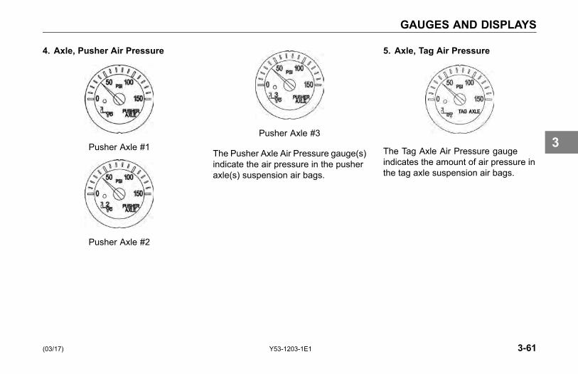
GAUGES AND DISPLAYS
4. Axle, Pusher Air Pressure
Pusher Axle #1
Pusher Axle #2
Pusher Axle #3
The Pusher Axle Air Pressure gauge(s)indicate the air pressure in the pusheraxle(s) suspension air bags.
5. Axle, Tag Air Pressure
The Tag Axle Air Pressure gaugeindicates the amount of air pressure inthe tag axle suspension air bags.
(03/17) Y53-1203-1E1 3-61
3
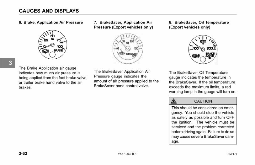
GAUGES AND DISPLAYS
6. Brake, Application Air Pressure
The Brake Application air gaugeindicates how much air pressure isbeing applied from the foot brake valveor trailer brake hand valve to the airbrakes.
7. BrakeSaver, Application AirPressure (Export vehicles only)
The BrakeSaver Application AirPressure gauge indicates theamount of air pressure applied to theBrakeSaver hand control valve.
8. BrakeSaver, Oil Temperature(Export vehicles only)
The BrakeSaver Oil Temperaturegauge indicates the temperature inthe BrakeSaver. If the oil temperatureexceeds the maximum limits, a redwarning lamp in the gauge will turn on.
CAUTIONThis should be considered an emer-gency. You should stop the vehicleas safely as possible and turn OFFthe ignition. The vehicle must beserviced and the problem correctedbefore driving again. Failure to do somay cause severe BrakeSaver dam-age.
3-62 Y53-1203-1E1 (03/17)
3
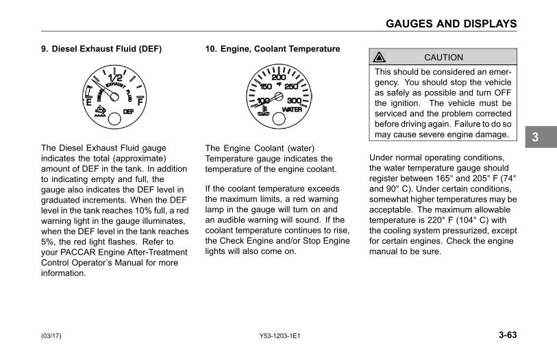
GAUGES AND DISPLAYS
9. Diesel Exhaust Fluid (DEF)
The Diesel Exhaust Fluid gaugeindicates the total (approximate)amount of DEF in the tank. In additionto indicating empty and full, thegauge also indicates the DEF level ingraduated increments. When the DEFlevel in the tank reaches 10% full, a redwarning light in the gauge illuminates,when the DEF level in the tank reaches5%, the red light flashes. Refer toyour PACCAR Engine After-TreatmentControl Operator’s Manual for moreinformation.
10. Engine, Coolant Temperature
The Engine Coolant (water)Temperature gauge indicates thetemperature of the engine coolant.
If the coolant temperature exceedsthe maximum limits, a red warninglamp in the gauge will turn on andan audible warning will sound. If thecoolant temperature continues to rise,the Check Engine and/or Stop Enginelights will also come on.
CAUTIONThis should be considered an emer-gency. You should stop the vehicleas safely as possible and turn OFFthe ignition. The vehicle must beserviced and the problem correctedbefore driving again. Failure to do somay cause severe engine damage.
Under normal operating conditions,the water temperature gauge shouldregister between 165° and 205° F (74°and 90° C). Under certain conditions,somewhat higher temperatures may beacceptable. The maximum allowabletemperature is 220° F (104° C) withthe cooling system pressurized, exceptfor certain engines. Check the enginemanual to be sure.
(03/17) Y53-1203-1E1 3-63
3
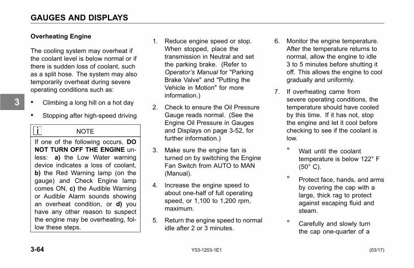
GAUGES AND DISPLAYS
Overheating Engine
The cooling system may overheat ifthe coolant level is below normal or ifthere is sudden loss of coolant, suchas a split hose. The system may alsotemporarily overheat during severeoperating conditions such as:
• Climbing a long hill on a hot day
• Stopping after high-speed driving
NOTEIf one of the following occurs, DONOT TURN OFF THE ENGINE un-less: a) the Low Water warningdevice indicates a loss of coolant,b) the Red Warning lamp (on thegauge) and Check Engine lampcomes ON, c) the Audible Warningor Audible Alarm sounds showingan overheat condition, or d) youhave any other reason to suspectthe engine may be overheating, fol-low these steps.
1. Reduce engine speed or stop.When stopped, place thetransmission in Neutral and setthe parking brake. (Refer toOperator’s Manual for "ParkingBrake Valve" and "Putting theVehicle in Motion" for moreinformation.)
2. Check to ensure the Oil PressureGauge reads normal. (See theEngine Oil Pressure in Gaugesand Displays on page 3-52, forfurther information.)
3. Make sure the engine fan isturned on by switching the EngineFan Switch from AUTO to MAN(Manual).
4. Increase the engine speed toabout one-half of full operatingspeed, or 1,100 to 1,200 rpm,maximum.
5. Return the engine speed to normalidle after 2 or 3 minutes.
6. Monitor the engine temperature.After the temperature returns tonormal, allow the engine to idle3 to 5 minutes before shutting itoff. This allows the engine to coolgradually and uniformly.
7. If overheating came fromsevere operating conditions, thetemperature should have cooledby this time. If it has not, stopthe engine and let it cool beforechecking to see if the coolant islow.
° Wait until the coolanttemperature is below 122° F(50° C).
° Protect face, hands, and armsby covering the cap with alarge, thick rag to protectagainst escaping fluid andsteam.
° Carefully and slowly turnthe cap one-quarter of a
3-64 Y53-1203-1E1 (03/17)
3
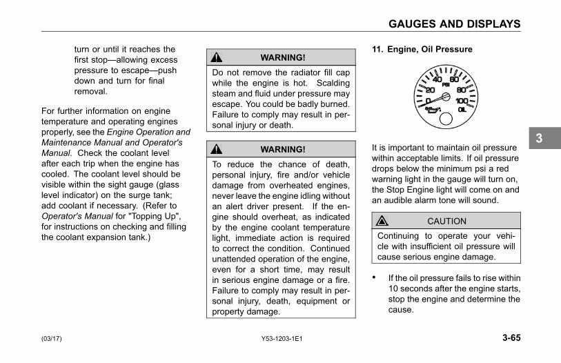
GAUGES AND DISPLAYS
turn or until it reaches thefirst stop—allowing excesspressure to escape—pushdown and turn for finalremoval.
For further information on enginetemperature and operating enginesproperly, see the Engine Operation andMaintenance Manual and Operator'sManual. Check the coolant levelafter each trip when the engine hascooled. The coolant level should bevisible within the sight gauge (glasslevel indicator) on the surge tank;add coolant if necessary. (Refer toOperator's Manual for "Topping Up",for instructions on checking and fillingthe coolant expansion tank.)
WARNING!Do not remove the radiator fill capwhile the engine is hot. Scaldingsteam and fluid under pressure mayescape. You could be badly burned.Failure to comply may result in per-sonal injury or death.
WARNING!To reduce the chance of death,personal injury, fire and/or vehicledamage from overheated engines,never leave the engine idling withoutan alert driver present. If the en-gine should overheat, as indicatedby the engine coolant temperaturelight, immediate action is requiredto correct the condition. Continuedunattended operation of the engine,even for a short time, may resultin serious engine damage or a fire.Failure to comply may result in per-sonal injury, death, equipment orproperty damage.
11. Engine, Oil Pressure
It is important to maintain oil pressurewithin acceptable limits. If oil pressuredrops below the minimum psi a redwarning light in the gauge will turn on,the Stop Engine light will come on andan audible alarm tone will sound.
CAUTIONContinuing to operate your vehi-cle with insufficient oil pressure willcause serious engine damage.
• If the oil pressure fails to rise within10 seconds after the engine starts,stop the engine and determine thecause.
(03/17) Y53-1203-1E1 3-65
3

GAUGES AND DISPLAYS
• Check the engine manufacturer'smanual for the correct oil pressureranges for your vehicle's engine.
• If the oil pressure suddenly drops,or the audible alarm and engineoil pressure warning light come onwhile driving, do the following:
1. Slow down carefully.
2. Move a safe distance off the roadand stop.
3. Place the transmission in park andset the parking brake. (Refer toOperator’s Manual for "ParkingBrake Valve" and "Operating theTransmission" for transmissionshifting and parking brakeinformation.)
4. Turn OFF the engine.
5. Turn ON the emergency flasherand use other warning devices toalert other motorists.
6. Wait a few minutes to allow oil todrain into the engine oil pan, andthen check the oil level. (Refer toOperator’s Manual for "Oil LevelCheck" for details on checking oillevel.)
7. Add oil if necessary. If the problempersists, contact an authorizedKenworth Dealer.
For further information on engine oiland normal operating pressures, seethe Engine Operation and MaintenanceManual.
For further information on enginegauges and operating your engineproperly, refer to Operator’s Manual for"Engine Maintenance".
12. Engine, Oil Temperature
The Engine Oil Temperature gaugeindicates the engine oil temperature.If the oil temperature exceeds themaximum limits, a red warninglight in the gauge will turn on. Donot exceed maximum engine oiltemperature recommended by theengine manufacturer. (See the EngineOperation and Maintenance Manualfor details.)
3-66 Y53-1203-1E1 (03/17)
3
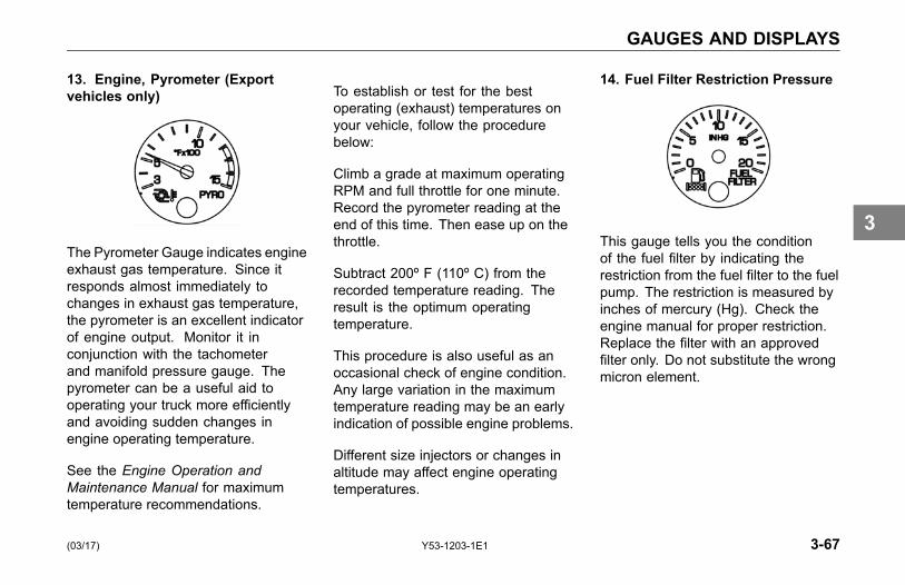
GAUGES AND DISPLAYS
13. Engine, Pyrometer (Exportvehicles only)
The Pyrometer Gauge indicates engineexhaust gas temperature. Since itresponds almost immediately tochanges in exhaust gas temperature,the pyrometer is an excellent indicatorof engine output. Monitor it inconjunction with the tachometerand manifold pressure gauge. Thepyrometer can be a useful aid tooperating your truck more efficientlyand avoiding sudden changes inengine operating temperature.
See the Engine Operation andMaintenance Manual for maximumtemperature recommendations.
To establish or test for the bestoperating (exhaust) temperatures onyour vehicle, follow the procedurebelow:
Climb a grade at maximum operatingRPM and full throttle for one minute.Record the pyrometer reading at theend of this time. Then ease up on thethrottle.
Subtract 200º F (110º C) from therecorded temperature reading. Theresult is the optimum operatingtemperature.
This procedure is also useful as anoccasional check of engine condition.Any large variation in the maximumtemperature reading may be an earlyindication of possible engine problems.
Different size injectors or changes inaltitude may affect engine operatingtemperatures.
14. Fuel Filter Restriction Pressure
This gauge tells you the conditionof the fuel filter by indicating therestriction from the fuel filter to the fuelpump. The restriction is measured byinches of mercury (Hg). Check theengine manual for proper restriction.Replace the filter with an approvedfilter only. Do not substitute the wrongmicron element.
(03/17) Y53-1203-1E1 3-67
3
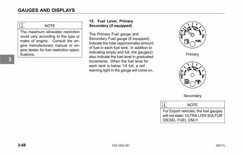
GAUGES AND DISPLAYS
NOTEThe maximum allowable restrictioncould vary according to the type ormake of engine. Consult the en-gine manufacturers manual or en-gine dealer for fuel restriction speci-fications.
15. Fuel Level, PrimarySecondary (if equipped)
The Primary Fuel gauge andSecondary Fuel gauge (if equipped)indicate the total (approximate) amountof fuel in each fuel tank. In addition toindicating empty and full, the gauge(s)also indicate the fuel level in graduatedincrements. When the fuel level foreach tank is below 1/4 full, a redwarning light in the gauge will come on.
Primary
Secondary
NOTEFor Export vehicles, the fuel gaugeswill not state: ULTRA LOWSULFURDIESEL FUEL ONLY.
3-68 Y53-1203-1E1 (03/17)
3
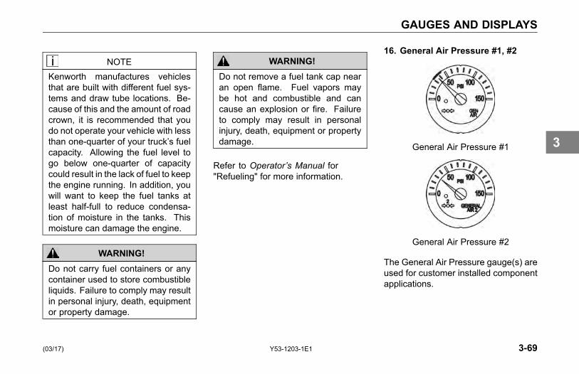
GAUGES AND DISPLAYS
NOTEKenworth manufactures vehiclesthat are built with different fuel sys-tems and draw tube locations. Be-cause of this and the amount of roadcrown, it is recommended that youdo not operate your vehicle with lessthan one-quarter of your truck’s fuelcapacity. Allowing the fuel level togo below one-quarter of capacitycould result in the lack of fuel to keepthe engine running. In addition, youwill want to keep the fuel tanks atleast half-full to reduce condensa-tion of moisture in the tanks. Thismoisture can damage the engine.
WARNING!Do not carry fuel containers or anycontainer used to store combustibleliquids. Failure to comply may resultin personal injury, death, equipmentor property damage.
WARNING!Do not remove a fuel tank cap nearan open flame. Fuel vapors maybe hot and combustible and cancause an explosion or fire. Failureto comply may result in personalinjury, death, equipment or propertydamage.
Refer to Operator’s Manual for"Refueling" for more information.
16. General Air Pressure #1, #2
General Air Pressure #1
General Air Pressure #2
The General Air Pressure gauge(s) areused for customer installed componentapplications.
(03/17) Y53-1203-1E1 3-69
3

GAUGES AND DISPLAYS
17. General Oil Temperature
The General Oil Temperature gauge(s)are used for customer installedcomponent applications.
18. Manifold Pressure (Turbo Boost)
The Manifold Pressure Gaugeindicates the power your vehiclesengine is putting out by showing theamount of turbo boost. If the pressureindicated by the manifold pressuregauge goes down, there may besomething wrong with the engine.Have it checked by a qualified serviceperson.
19. Primary and Secondary AirPressure
Primary Air Pressure
Secondary Air Pressure
The Primary Air Pressure gaugeindicates pressure in the rear brakingsystem. The Secondary gaugeindicates pressure in the front brakingsystem. Each gauge indicates the
3-70 Y53-1203-1E1 (03/17)
3
GAUGES AND DISPLAYS
amount of air pressure in each systemin pounds per square inch (psi).
On vehicles equipped with metric airpressure gauges, the gauge face plateincludes a kPa (major) scale and psi(minor) scale.
NOTEBe sure the air pressure registersmore than 100 psi (689 kPa) in bothservice systems before you movethe vehicle.
NOTEIf the pressure in either or both cir-cuits falls below 65 psi (448 kPa),a red warning light in the gauge willturn on and an audible alarm tonewill sound when the engine is run-ning.
WARNING!If the air pressure falls below 60 psi(414 kPa), the spring brakes maystop the vehicle abruptly which couldcause an accident resulting in per-sonal injury or death. Observe thered warning lamps on the gauges.If one comes on, do not continueto drive the vehicle until it has beenproperly repaired or serviced.
WARNING!The air pressure warning light andthe audible alarm tone indicate adangerous situation: there is notenough air pressure in the air tanksfor repeated braking and the brakesystem has failed. Without the useof your service brakes your springbrakes could suddenly apply caus-ing a wheel lock-up, loss of control,or over-take by following vehicles.This may cause an accident result-ing in personal injury or death. Bringthe vehicle to a safe stop right away,while you still have control of thevehicle. Refer to the following pro-cedure:
(03/17) Y53-1203-1E1 3-71
3
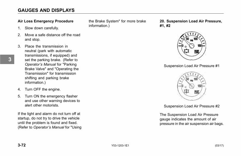
GAUGES AND DISPLAYS
Air Loss Emergency Procedure
1. Slow down carefully.
2. Move a safe distance off the roadand stop.
3. Place the transmission inneutral (park with automatictransmissions, if equipped) andset the parking brake. (Refer toOperator’s Manual for "ParkingBrake Valve" and "Operating theTransmission" for transmissionshifting and parking brakeinformation.)
4. Turn OFF the engine.
5. Turn ON the emergency flasherand use other warning devices toalert other motorists.
If the light and alarm do not turn off atstartup, do not try to drive the vehicleuntil the problem is found and fixed.(Refer to Operator’s Manual for "Using
the Brake System" for more brakeinformation.)
20. Suspension Load Air Pressure,#1, #2
Suspension Load Air Pressure #1
Suspension Load Air Pressure #2
The Suspension Load Air Pressuregauge indicates the amount of airpressure in the air suspension air bags.
3-72 Y53-1203-1E1 (03/17)
3
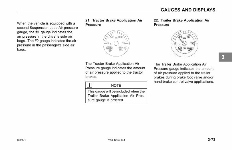
GAUGES AND DISPLAYS
When the vehicle is equipped with asecond Suspension Load Air pressuregauge, the #1 gauge indicates theair pressure in the driver's side airbags. The #2 gauge indicates the airpressure in the passenger's side airbags.
21. Tractor Brake Application AirPressure
The Tractor Brake Application AirPressure gauge indicates the amountof air pressure applied to the tractorbrakes.
NOTEThis gauge will be included when theTrailer Brake Application Air Pres-sure gauge is ordered.
22. Trailer Brake Application AirPressure
The Trailer Brake Application AirPressure gauge indicates the amountof air pressure applied to the trailerbrakes during brake foot valve and/orhand brake control valve applications.
(03/17) Y53-1203-1E1 3-73
3
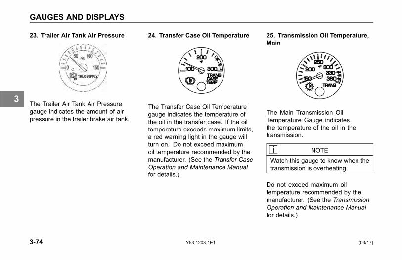
GAUGES AND DISPLAYS
23. Trailer Air Tank Air Pressure
The Trailer Air Tank Air Pressuregauge indicates the amount of airpressure in the trailer brake air tank.
24. Transfer Case Oil Temperature
The Transfer Case Oil Temperaturegauge indicates the temperature ofthe oil in the transfer case. If the oiltemperature exceeds maximum limits,a red warning light in the gauge willturn on. Do not exceed maximumoil temperature recommended by themanufacturer. (See the Transfer CaseOperation and Maintenance Manualfor details.)
25. Transmission Oil Temperature,Main
The Main Transmission OilTemperature Gauge indicatesthe temperature of the oil in thetransmission.
NOTEWatch this gauge to know when thetransmission is overheating.
Do not exceed maximum oiltemperature recommended by themanufacturer. (See the TransmissionOperation and Maintenance Manualfor details.)
3-74 Y53-1203-1E1 (03/17)
3

GAUGES AND DISPLAYS
26. Transmission Oil Temperature,Auxiliary
The Auxiliary Transmission OilTemperature gauge indicates thetemperature of the oil in the auxiliarytransmission.
NOTEWatch this gauge to know when thetransmission is overheating.
Do not exceed maximum oiltemperature recommended by themanufacturer. (See the TransmissionOperation and Maintenance Manualfor details.)
27. Transmission Retarder OilTemperature
The Transmission Retarder OilTemperature gauge indicatesthe temperature of the oil in thetransmission retarder.
NOTEWatch this gauge to know when thetransmission is overheating.
Do not exceed maximum oiltemperature recommended by themanufacturer. (See the TransmissionOperation and Maintenance Manualfor details.)
28. Voltmeter
The Voltmeter displays the batteryvoltage. Normally, it should show 12 to14V (volts). A red warning light in thegauge turns on when an out of rangecondition exists.
NOTEEven with a healthy charge/startsystem, the voltmeter may fall wellbelow 12V during engine cranking.If voltage drops below 12V and staysthere, have the electrical systemchecked.
(03/17) Y53-1203-1E1 3-75
3
GAUGES AND DISPLAYS
Multi-Function Display(Option)
(Refer to Kenworth Multi-FunctionDisplay Operator Manual)
Bendix Wingman® Active Cruisewith Braking (ACB)
• Your vehicle may be equipped witha Bendix Wingman® Active Cruisewith Braking (ACB) system. Thissystem is an integrated feature ofthe vehicle cruise control whichwill slow the vehicle to maintain aset following distance. The speedreduction may be accomplished byan engine de-throttle, applicationof engine retarder, and applicationof foundation brakes.
• Driver alerts and stationary objectalerts are a feature of the BendixWingman® Active Cruise withBraking (ACB) system and arealways active regardless of thevehicle’s cruise control status.These alerts are intended solelyas a supplement to the existingwindows and mirrors of yourvehicle and should strictly beused as an aid for an attentiveand conscientious professional
driver. They are not to be solelyrelied upon to operate a vehicleand should be used in conjunctionwith rear view mirrors, windowsand any other applicable device ormethod to operate the vehicle in asafe manner.
• The Bendix Wingman® ActiveCruise with Braking (ACB) systemincludes a front sensor andsingle RH side sensor along withdriver and side displays. Thisoption provides Active Cruise withBraking and side object detection.Side object detection is an optionaladd-on to Bendix Wingman®Active Cruise with Braking (ACB)and may not be present.
3-76 Y53-1203-1E1 (03/17)
3

GAUGES AND DISPLAYS
NOTEBefore operating the system, readand understand the Bendix Wing-man® Active Cruise with Braking(ACB) Operator’s Manual providedwith your vehicle. In addition, ob-serve all Warnings, Cautions, andNotes in the Operator’s Manual andlisted below.
WARNING!Ultimate responsibility for the safeoperation of the vehicle remains withthe driver at all times. Even withBendix Wingman® Active Cruisewith Braking (ACB), you must re-main alert, react appropriately andin a timely manner, and use gooddriving practices. Failure to complymay result in personal injury, death,equipment or property damage.
WARNING!Bendix Wingman® Active Cruisewith Braking (ACB) reacts to vehi-cles moving in the same directionas your vehicle. The system doesnot attempt to brake the vehiclewhen approaching stopped vehi-cles, side-to-side moving traffic, oroncoming traffic. Failure to complymay result in personal injury, death,equipment or property damage.
WARNING!The Bendix Wingman® ActiveCruise with Braking (ACB) driveralerts will not warn of all potentialhazards. Do not assume "all is clear"if no warning signals are indicated.This system is intended solely asa driver aid and supplement to ex-isting visual aids, and should notbe relied upon to operate a vehicle.Use the Bendix Wingman® ActiveCruise with Braking (ACB) system inconjunction with rear view mirrors,windows and any other applicabledevice or method to operate the ve-hicle in a safe manner. Failure tocomply may result in personal injury,death, equipment or property dam-age.
(03/17) Y53-1203-1E1 3-77
3

GAUGES AND DISPLAYS
WARNING!The Bendix Wingman® ActiveCruise with Braking (ACB) systemshould never be used on roadswhere you cannot drive safely at asteady speed including city streets,winding roads and sharp curves,downhill grades, poor road con-ditions such as gravel, dirt, iceor wet surfaces, or in fog, heavyrain, or snowy conditions. In cer-tain situations Bendix Wingman®Active Cruise with Braking (ACB)should not be used including in-clement weather, dense traffic orwhere smaller vehicles such as mo-torcycles are ahead in the samelane, construction zones, off-roaduse, downhill grades, when enter-ing turning lanes, entering or exitinghighways, or similar situations. Fail-ure to comply may result in personalinjury, death, equipment or propertydamage.
Vehicle ConfigurationChanges–Limitations andGuidelines
• The positioning of the variouscomponents of the BendixWingman® Active Cruise withBraking (ACB) system has beendesigned for your vehicle. Prior toadding any SAE J1939 equippeddevices, or changing the vehicle’sframe height or relocating theBendix Wingman® Active Cruisewith Braking (ACB) sensors,please contact your nearestKenworth authorized dealer toensure that your planned changesdo not effect the operation ofperformance of the BendixWingman® Active Cruise withBraking (ACB) system. Forfurther information, you cancontact the Bendix Tech Team at1-800-AIR-BRAK (247-2725).
WARNING!The addition of SAE J1939 databus communication equipped de-vices have the potential to disruptthe other SAE J1939 data compo-nents, including but not limited toengine controls, transmissions andBendix Wingman® Active Cruisewith Braking (ACB). Do not addany additional SAE J1939 equippeddevices. Any unauthorized or uncer-tified SAE J1939 equipped devicesadded to the vehicle may result inthe SAE J1939 communication linkto not perform as designed. Failureto comply may result in personalinjury, death, equipment or propertydamage.
3-78 Y53-1203-1E1 (03/17)
3
GAUGES AND DISPLAYS
WARNING!The front radar has been aligned perBendix’s installation guidelines. Ifyou are in an accident that involvesthe front bumper or the radar’s align-ment, the radar needs to be checkedand adjusted prior to placing the ve-hicle into service. Kenworth stronglyrecommends that if your vehicle wasinvolved in a frontal accident, youhave the system checked by an au-thorized Kenworth dealer. Failure todo so may result in the degradationof system performance. Failure tocomply may result in personal injury,death, equipment or property dam-age.
WARNING!The location and height of theBendix Wingman® Active Cruisewith Braking (ACB) front radar andside sensor position was specificallydesigned for your vehicle per Bendixrequirements. The elevation andlocation of the radar and side sen-sor are critical for proper operationof the system. Any changes to thevehicle frame height or side sensorlocation, including but not limitedto tire radius changes must be ap-proved by Bendix. Any changesthat affect the location of the radarand/or side sensor may result in thedegradation of system performance.Failure to comply may result in per-sonal injury, death, equipment orproperty damage.
(03/17) Y53-1203-1E1 3-79
3
MULTI-FUNCTION DISPLAY
MULTI-FUNCTIONDISPLAY
Introduction
This section explains the location andfunction of the various instruments andcontrols on your vehicle.
Please remember that each Kenworthis custom made. Your instrument panelmay not look exactly like the one inthe illustration below. Described beloware the most common instruments andcontrols available.
Alarms, Warning Tones andVisual Indicator LightsIntroduction
Your vehicle's dash andinstrumentation uses variousmethods to indicate to you the statusof various systems, or that one ormore of your vehicle's systems maybe malfunctioning. The methodto communicate or alert you of aparticular condition is by:
• Audible alarm tone
• Audible warning tone
• Indicator light(s)
In some cases, you may have both analarm or warning tone accompanied byan indicator light(s).
WARNING!Do not ignore any type of tone orlights. These signals tell you thatsomething is malfunctioning on yourvehicle and provide you an indi-cation of what system is affected.It could be a failure of an impor-tant system, such as the brakes,which could lead to an accident andmay result in personal injury, death,equipment or property damage.
3-80 Y53-1203-1E1 (03/17)
3
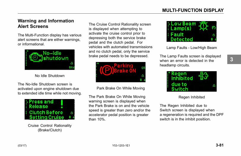
MULTI-FUNCTION DISPLAY
Warning and InformationAlert Screens
The Multi-Function display has variousalert screens that are either warnings,or informational.
No Idle Shutdown
The No-Idle Shutdown screen isactivated upon engine shutdown dueto extended idle time while not moving.
Cruise Control Rationality(Brake/Clutch)
The Cruise Control Rationality screenis displayed when attempting toactivate the cruise control prior todepressing both the service brakepedal and the clutch pedal. Forvehicles with automated transmissionsand no clutch pedal, only the servicebrake pedal needs to be depressed.
Park Brake On While Moving
The Park Brake On While Movingwarning screen is displayed whenthe Park Brake is on and the vehiclespeed is greater than zero and/or theaccelerator pedal position is greaterthan 10%.
Lamp Faults - Low/High Beam
The Lamp Faults screen is displayedwhen an error is detected in theheadlamp circuits.
Regen Inhibited
The Regen Inhibited due toSwitch screen is displayed whena regeneration is required and the DPFswitch is in the inhibit positiion.
(03/17) Y53-1203-1E1 3-81
3
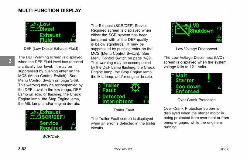
MULTI-FUNCTION DISPLAY
DEF (Low Diesel Exhaust Fluid)
The DEF Warning screen is displayedwhen the DEF Fluid level has reacheda critically low level. It may besuppressed by pushing enter on theMCS (Menu Control Switch). SeeMenu Control Switch on page 3-89.This warning may be accompanied bythe DEF Level in the low range, DEFLamp on solid or flashing, the CheckEngine lamp, the Stop Engine lamp,the MIL lamp, and/or engine de-rate.
SCR/DEF
The Exhaust (SCR/DEF) ServiceRequired screen is displayed wheneither the SCR system has beentampered with or the DEF qualityis below standards. It may besuppressed by pushing enter on theMCS (Menu Control Switch). SeeMenu Control Switch on page 3-89.This warning may be accompaniedby the DEF Lamp flashing, the CheckEngine lamp, the Stop Engine lamp,the MIL lamp, and/or engine de-rate.
Trailer Fault
The Trailer Fault screen is displayedwhen an error is detected in the trailercircuits.
Low Voltage Disconnect
The Low Voltage Disconnect (LVD)screen is displayed when the systemvoltage falls to 12.1 volts.
Over-Crank Protection
Over-Crank Protection screen isdisplayed when the starter motor isbeing protected from over heat or frombeing engaged while the engine isrunning.
3-82 Y53-1203-1E1 (03/17)
3
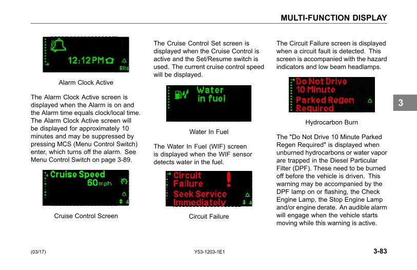
MULTI-FUNCTION DISPLAY
Alarm Clock Active
The Alarm Clock Active screen isdisplayed when the Alarm is on andthe Alarm time equals clock/local time.The Alarm Clock Active screen willbe displayed for approximately 10minutes and may be suppressed bypressing MCS (Menu Control Switch)enter, which turns off the alarm. SeeMenu Control Switch on page 3-89.
Cruise Control Screen
The Cruise Control Set screen isdisplayed when the Cruise Control isactive and the Set/Resume switch isused. The current cruise control speedwill be displayed.
Water In Fuel
The Water In Fuel (WIF) screenis displayed when the WIF sensordetects water in the fuel.
Circuit Failure
The Circuit Failure screen is displayedwhen a circuit fault is detected. Thisscreen is accompanied with the hazardindicators and low beam headlamps.
Hydrocarbon Burn
The "Do Not Drive 10 Minute ParkedRegen Required" is displayed whenunburned hydrocarbons or water vaporare trapped in the Diesel ParticularFilter (DPF). These need to be burnedoff before the vehicle is driven. Thiswarning may be accompanied by theDPF lamp on or flashing, the CheckEngine Lamp, the Stop Engine Lampand/or engine derate. An audible alarmwill engage when the vehicle startsmoving while this warning is active.
(03/17) Y53-1203-1E1 3-83
3
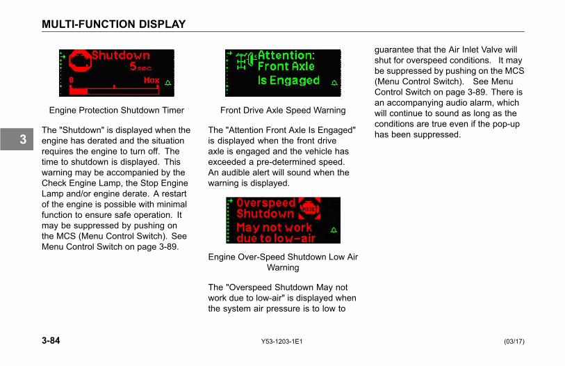
MULTI-FUNCTION DISPLAY
Engine Protection Shutdown Timer
The "Shutdown" is displayed when theengine has derated and the situationrequires the engine to turn off. Thetime to shutdown is displayed. Thiswarning may be accompanied by theCheck Engine Lamp, the Stop EngineLamp and/or engine derate. A restartof the engine is possible with minimalfunction to ensure safe operation. Itmay be suppressed by pushing onthe MCS (Menu Control Switch). SeeMenu Control Switch on page 3-89.
Front Drive Axle Speed Warning
The "Attention Front Axle Is Engaged"is displayed when the front driveaxle is engaged and the vehicle hasexceeded a pre-determined speed.An audible alert will sound when thewarning is displayed.
Engine Over-Speed Shutdown Low AirWarning
The "Overspeed Shutdown May notwork due to low-air" is displayed whenthe system air pressure is to low to
guarantee that the Air Inlet Valve willshut for overspeed conditions. It maybe suppressed by pushing on the MCS(Menu Control Switch). See MenuControl Switch on page 3-89. There isan accompanying audio alarm, whichwill continue to sound as long as theconditions are true even if the pop-uphas been suppressed.
3-84 Y53-1203-1E1 (03/17)
3

MULTI-FUNCTION DISPLAY
What You Should Do
If an alert screen comes on whiledriving, do the following:
1. Slow down carefully.
2. Move a safe distance off the roadand stop.
3. Set the parking brake. (Refer toOperator’s Manual for "Operatingthe Transmission" and "Operatingthe Brake System".)
4. If the engine is overheating donot turn it off (see "OverheatingEngine" in the Operator’s Manual);otherwise, for other conditions turnthe engine OFF.
5. Turn on the emergency flasherand use other warning devices toalert other motorists.
Wingman® ACB WarningTone / Alert Screens• Series of high pitched rings that
repeat at different rates. See thefollowing warning descriptions andcorresponding number of tonesper minute.
• Indicates one of the followingscenarios; your vehicle is too closeto the vehicle ahead, a stationaryobject has been detected, or thereis an active fault in the Wingman®ACB system.
Level 3 Following Distance Alert
This Wingman® ACB warning tone isactive when the following distance isless than what is set in the Wingman®
ACB system. This is the least severeof all the ACB warning tones. The highpitched ring will have a single beeprepeating at a rate of 42 tones perminute.
Level 2 Following Distance Alert
This Wingman® ACB warning tone isactive when the following distance isless than what is set in the Wingman®ACB system. This ACB warningtone is more severe than the Level3 Following Distance Alert. The highpitched ring will have a double beeprepeating at a rate of 80 tones perminute (40 double beeps per minute).
(03/17) Y53-1203-1E1 3-85
3
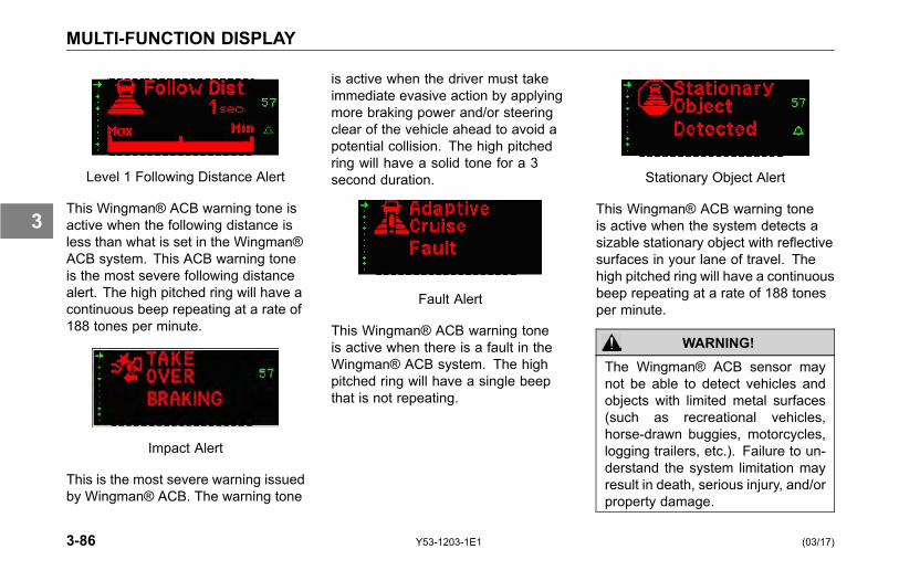
MULTI-FUNCTION DISPLAY
Level 1 Following Distance Alert
This Wingman® ACB warning tone isactive when the following distance isless than what is set in the Wingman®ACB system. This ACB warning toneis the most severe following distancealert. The high pitched ring will have acontinuous beep repeating at a rate of188 tones per minute.
Impact Alert
This is the most severe warning issuedby Wingman® ACB. The warning tone
is active when the driver must takeimmediate evasive action by applyingmore braking power and/or steeringclear of the vehicle ahead to avoid apotential collision. The high pitchedring will have a solid tone for a 3second duration.
Fault Alert
This Wingman® ACB warning toneis active when there is a fault in theWingman® ACB system. The highpitched ring will have a single beepthat is not repeating.
Stationary Object Alert
This Wingman® ACB warning toneis active when the system detects asizable stationary object with reflectivesurfaces in your lane of travel. Thehigh pitched ring will have a continuousbeep repeating at a rate of 188 tonesper minute.
WARNING!The Wingman® ACB sensor maynot be able to detect vehicles andobjects with limited metal surfaces(such as recreational vehicles,horse-drawn buggies, motorcycles,logging trailers, etc.). Failure to un-derstand the system limitation mayresult in death, serious injury, and/orproperty damage.
3-86 Y53-1203-1E1 (03/17)
3
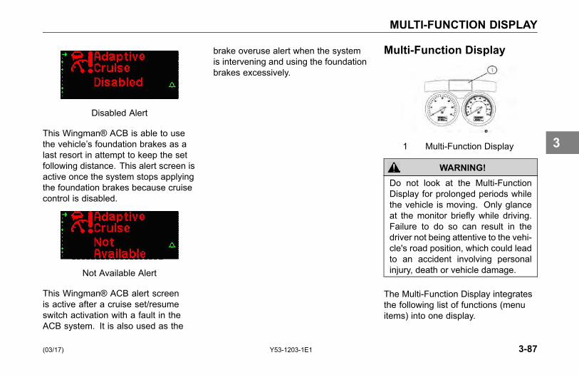
MULTI-FUNCTION DISPLAY
Disabled Alert
This Wingman® ACB is able to usethe vehicle’s foundation brakes as alast resort in attempt to keep the setfollowing distance. This alert screen isactive once the system stops applyingthe foundation brakes because cruisecontrol is disabled.
Not Available Alert
This Wingman® ACB alert screenis active after a cruise set/resumeswitch activation with a fault in theACB system. It is also used as the
brake overuse alert when the systemis intervening and using the foundationbrakes excessively.
Multi-Function Display
1 Multi-Function Display
WARNING!Do not look at the Multi-FunctionDisplay for prolonged periods whilethe vehicle is moving. Only glanceat the monitor briefly while driving.Failure to do so can result in thedriver not being attentive to the vehi-cle's road position, which could leadto an accident involving personalinjury, death or vehicle damage.
The Multi-Function Display integratesthe following list of functions (menuitems) into one display.
(03/17) Y53-1203-1E1 3-87
3
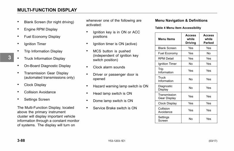
MULTI-FUNCTION DISPLAY
• Blank Screen (for night driving)
• Engine RPM Display
• Fuel Economy Display
• Ignition Timer
• Trip Information Display
• Truck Information Display
• On-Board Diagnostic Display
• Transmission Gear Display(automated transmissions only)
• Clock Display
• Collision Avoidance
• Settings Screen
The Multi-Function Display, locatedabove the primary instrumentcluster will display important vehicleinformation through a constant monitorof systems. The display will turn on
whenever one of the following areactivated:
• Ignition key is in ON or ACCpositions
• Ignition timer is ON (active)
• MCS button is pushed(independent of ignition keyswitch position)
• Clock alarm sounds
• Driver or passenger door isopened
• Hazard warning lamp switch is ON
• Head lamp switch is ON
• Dome lamp switch is ON
• Service Brake switch is ON
Menu Navigation & Definitions
Table 4 Menu Item Accessibility
Menu ItemsAccesswhileDriving
AccesswhileParked
Blank Screen Yes Yes
Fuel Economy Yes No
RPM Detail Yes Yes
Ignition Timer No Yes
TripInformation Yes Yes
TruckInformation No Yes
DiagnosticDisplay No Yes
TransmissionGear Display Yes Yes
Clock Display Yes Yes
CollisionAvoidance Yes Yes
SettingsScreen No Yes
3-88 Y53-1203-1E1 (03/17)
3
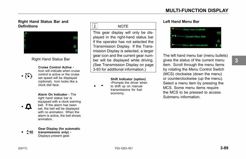
MULTI-FUNCTION DISPLAY
Right Hand Status Bar andDefinitions
Right Hand Status Bar
●
Cruise Control Active -Icon will indicate when cruisecontrol is active or the cruiseset speed will be displayed(optional). Icon looks like aclock dial face.
●
Alarm On Indicator - Theright hand status bar isequipped with a clock warningbell. If the alarm has beenset, the bell will be displayedwith no animation. When thealarm is active, the bell showsanimation.
●Gear Display (for automatictransmissions only) -Displays present gear.
NOTEThis gear display will only be dis-played in the right-hand status barif the operator has not selected theTransmission Display. If the Trans-mission Display is selected, a largergear icon and the current gear num-ber will be displayed while driving.(See Transmission Display on page3-93 for additional information.)
●
Shift Indicator (option)-Prompts the driver whento shift up on manualtransmissions for fueleconomy.
Left Hand Menu Bar
The left hand menu bar (menu bullets)gives the status of the current menuitem. Scroll through the menu itemsby rotating the Menu Control Switch(MCS) clockwise (down the menu)or counterclockwise (up the menu).Select a menu item by pressing theMCS. Some menu items requirethe MCS to be pressed to accessSubmenu information.
(03/17) Y53-1203-1E1 3-89
3
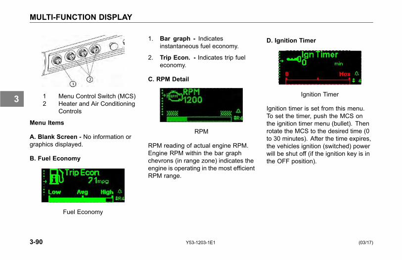
MULTI-FUNCTION DISPLAY
1 Menu Control Switch (MCS)2 Heater and Air Conditioning
Controls
Menu Items
A. Blank Screen - No information orgraphics displayed.
B. Fuel Economy
Fuel Economy
1. Bar graph - Indicatesinstantaneous fuel economy.
2. Trip Econ. - Indicates trip fueleconomy.
C. RPM Detail
RPM
RPM reading of actual engine RPM.Engine RPM within the bar graphchevrons (in range zone) indicates theengine is operating in the most efficientRPM range.
D. Ignition Timer
Ignition Timer
Ignition timer is set from this menu.To set the timer, push the MCS onthe ignition timer menu (bullet). Thenrotate the MCS to the desired time (0to 30 minutes). After the time expires,the vehicles ignition (switched) powerwill be shut off (if the ignition key is inthe OFF position).
3-90 Y53-1203-1E1 (03/17)
3
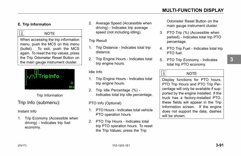
MULTI-FUNCTION DISPLAY
E. Trip Information
NOTEWhen accessing the trip informationmenu, push the MCS on this menu(bullet). To exit, push the MCSagain. To reset the trip values, pressthe Trip Odometer Reset Button onthe main gauge instrument cluster.
Trip Information
Trip Info (submenu):
Instant Info
1. Trip Economy (Accessible whendriving) - Indicates trip fueleconomy.
2. Average Speed (Accessible whendriving) - Indicates trip averagespeed (not including idling).
Trip Result
1. Trip Distance - Indicates total tripdistance.
2. Trip Engine Hours - Indicates totaltrip engine hours.
Idle Info
1. Trip Engine Hours - Indicates totaltrip engine hours.
2. Trip Idle Percentage (%) -Indicates total trip idle percentage.
PTO Info (Optional)
1. PTO Hours - Indicates total vehiclePTO operation hours.
2. PTO Trip Hours - Indicates totaltrip PTO operation hours. To resetthe Trip Values, press the Trip
Odometer Reset Button on themain gauge instrument cluster.
3. PTO Trip (%) (Accessible whenparked) - Indicates total trip PTOpercentage.
4. PTO Trip Fuel - Indicates total tripPTO fuel.
5. PTO Trip Economy - Indicatestotal trip PTO economy.
NOTEDisplay functions for PTO hours,PTO Trip Hours and PTO Trip Per-centage will only be available if sup-ported by the engine installed. If thetruck has a factory-installed PTO,these fields will appear in the TripInformation screen. If the enginedoes not support the data, dasheswill be shown.
(03/17) Y53-1203-1E1 3-91
3
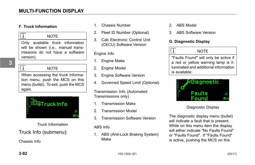
MULTI-FUNCTION DISPLAY
F. Truck Information
NOTEOnly available truck informationwill be shown (i.e., manual trans-missions do not have a softwareversion).
NOTEWhen accessing the truck informa-tion menu, push the MCS on thismenu (bullet). To exit, push theMCSagain.
Truck Information
Truck Info (submenu):
Chassis Info
1. Chassis Number
2. Fleet ID Number (Optional)
3. Cab Electronic Control Unit(CECU) Software Version
Engine Info
1. Engine Make
2. Engine Model
3. Engine Software Version
4. Governed Speed Limit (Optional)
Transmission Info (AutomatedTransmissions only)
1. Transmission Make
2. Transmission Model
3. Transmission Software Version
ABS Info
1. ABS (Anti-Lock Braking System)Make
2. ABS Model
3. ABS Software Version
G. Diagnostic Display
NOTE"Faults Found" will only be active ifa red or yellow warning lamp is il-luminated and additional informationis available.
Diagnostic Display
The diagnostic display menu (bullet)will indicate a fault that is present.While on this menu item the displaywill either indicate "No Faults Found"or "Faults Found". If "Faults Found"is active, pushing the MCS on this
3-92 Y53-1203-1E1 (03/17)
3
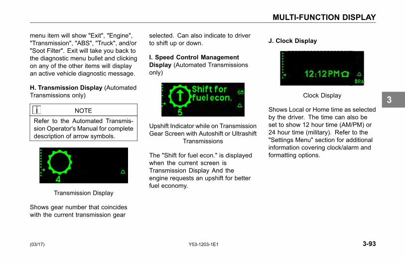
MULTI-FUNCTION DISPLAY
menu item will show "Exit", "Engine","Transmission", "ABS", "Truck", and/or"Soot Filter". Exit will take you back tothe diagnostic menu bullet and clickingon any of the other items will displayan active vehicle diagnostic message.
H. Transmission Display (AutomatedTransmissions only)
NOTERefer to the Automated Transmis-sion Operator's Manual for completedescription of arrow symbols.
Transmission Display
Shows gear number that coincideswith the current transmission gear
selected. Can also indicate to driverto shift up or down.
I. Speed Control ManagementDisplay (Automated Transmissionsonly)
Upshift Indicator while on TransmissionGear Screen with Autoshift or Ultrashift
Transmissions
The "Shift for fuel econ." is displayedwhen the current screen isTransmission Display And theengine requests an upshift for betterfuel economy.
J. Clock Display
Clock Display
Shows Local or Home time as selectedby the driver. The time can also beset to show 12 hour time (AM/PM) or24 hour time (military). Refer to the"Settings Menu" section for additionalinformation covering clock/alarm andformatting options.
(03/17) Y53-1203-1E1 3-93
3
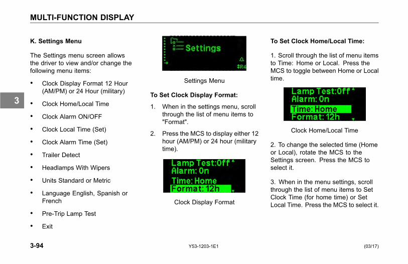
MULTI-FUNCTION DISPLAY
K. Settings Menu
The Settings menu screen allowsthe driver to view and/or change thefollowing menu items:
• Clock Display Format 12 Hour(AM/PM) or 24 Hour (military)
• Clock Home/Local Time
• Clock Alarm ON/OFF
• Clock Local Time (Set)
• Clock Alarm Time (Set)
• Trailer Detect
• Headlamps With Wipers
• Units Standard or Metric
• Language English, Spanish orFrench
• Pre-Trip Lamp Test
• Exit
Settings Menu
To Set Clock Display Format:
1. When in the settings menu, scrollthrough the list of menu items to"Format".
2. Press the MCS to display either 12hour (AM/PM) or 24 hour (militarytime).
Clock Display Format
To Set Clock Home/Local Time:
1. Scroll through the list of menu itemsto Time: Home or Local. Press theMCS to toggle between Home or Localtime.
Clock Home/Local Time
2. To change the selected time (Homeor Local), rotate the MCS to theSettings screen. Press the MCS toselect it.
3. When in the menu settings, scrollthrough the list of menu items to SetClock Time (for home time) or SetLocal Time. Press the MCS to select it.
3-94 Y53-1203-1E1 (03/17)
3
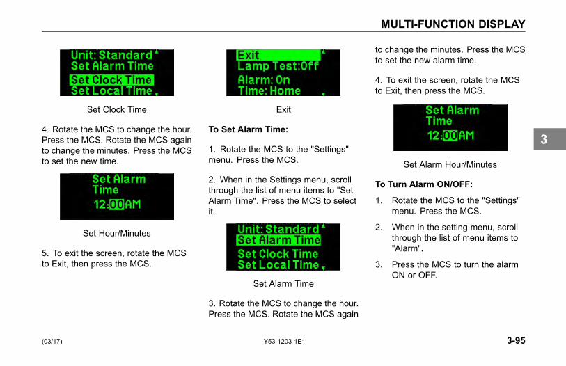
MULTI-FUNCTION DISPLAY
Set Clock Time
4. Rotate the MCS to change the hour.Press the MCS. Rotate the MCS againto change the minutes. Press the MCSto set the new time.
Set Hour/Minutes
5. To exit the screen, rotate the MCSto Exit, then press the MCS.
Exit
To Set Alarm Time:
1. Rotate the MCS to the "Settings"menu. Press the MCS.
2. When in the Settings menu, scrollthrough the list of menu items to "SetAlarm Time". Press the MCS to selectit.
Set Alarm Time
3. Rotate the MCS to change the hour.Press the MCS. Rotate the MCS again
to change the minutes. Press the MCSto set the new alarm time.
4. To exit the screen, rotate the MCSto Exit, then press the MCS.
Set Alarm Hour/Minutes
To Turn Alarm ON/OFF:
1. Rotate the MCS to the "Settings"menu. Press the MCS.
2. When in the setting menu, scrollthrough the list of menu items to"Alarm".
3. Press the MCS to turn the alarmON or OFF.
(03/17) Y53-1203-1E1 3-95
3
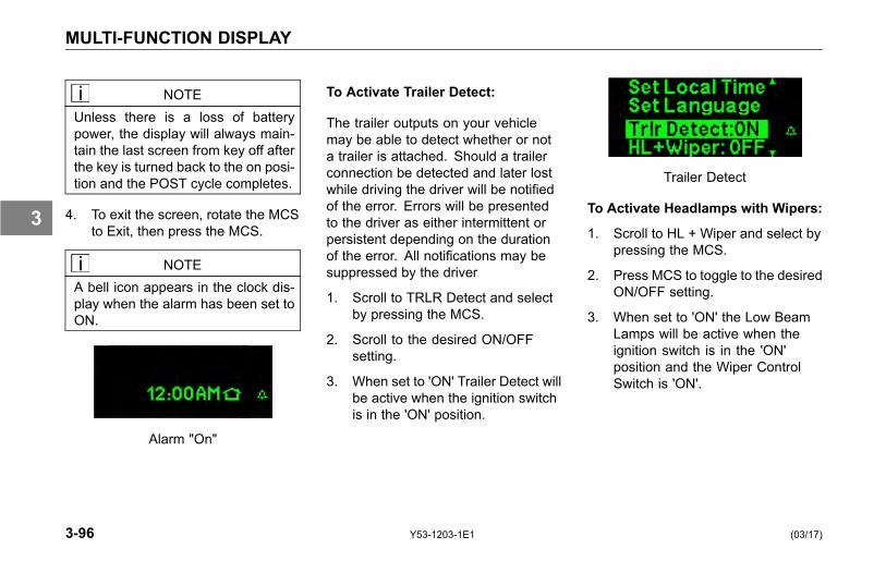
MULTI-FUNCTION DISPLAY
NOTEUnless there is a loss of batterypower, the display will always main-tain the last screen from key off afterthe key is turned back to the on posi-tion and the POST cycle completes.
4. To exit the screen, rotate the MCSto Exit, then press the MCS.
NOTEA bell icon appears in the clock dis-play when the alarm has been set toON.
Alarm "On"
To Activate Trailer Detect:
The trailer outputs on your vehiclemay be able to detect whether or nota trailer is attached. Should a trailerconnection be detected and later lostwhile driving the driver will be notifiedof the error. Errors will be presentedto the driver as either intermittent orpersistent depending on the durationof the error. All notifications may besuppressed by the driver
1. Scroll to TRLR Detect and selectby pressing the MCS.
2. Scroll to the desired ON/OFFsetting.
3. When set to 'ON' Trailer Detect willbe active when the ignition switchis in the 'ON' position.
Trailer Detect
To Activate Headlamps with Wipers:
1. Scroll to HL + Wiper and select bypressing the MCS.
2. Press MCS to toggle to the desiredON/OFF setting.
3. When set to 'ON' the Low BeamLamps will be active when theignition switch is in the 'ON'position and the Wiper ControlSwitch is 'ON'.
3-96 Y53-1203-1E1 (03/17)
3

MULTI-FUNCTION DISPLAY
Headlamps with Wipers
To Set Standard or Metric Units:
1. Rotate the MCS to the "Settings"menu. Press the MCS.
2. When in the Settings menu, scrollthrough the list of menu items to"Units". Press the MCS to displayeither Standard or Metric units.
To Set Language:
1. Rotate the MCS knob to the"Settings" menu. Press the MCS.
2. When in the Settings menu, scrollthrough the list of menu items to"Language". Press the MCS todisplay either English, Spanish orFrench.
L. Pre-trip Lamp Test
When activated with the MCS, ‘Pre-tripLamp Test Active’ appears on theMulti-function display and will reappearperiodically while the test is active. Thetest will illuminate the following lamps:
Lamp SequenceMarker* 1, 2
Clearance* 1, 2
Headlamp low-beam 1
Headlamp high-beam 2
Auxiliary (fog or driving) 1, 2
Stop 2
Park* 1, 2
Hazard/Turn lamps 1
All lamps with sequence #1 willilluminate simultaneously for 10seconds. All lamps with sequence#2 will illuminate simultaneously for10 seconds immediately followingsequence #1. Each sequence will
illuminate lamps for 10 seconds.With the default settings and withoutintervention the Pre-trip Lamp Test willdeactivate after 10 minutes. Sequencetime can vary from 10 seconds with a10 minute duration up to 30 secondsand a 30 minute duration.
Asterisks (*) indicate that dash switchmust be ON for the Pre-trip Self Test tooperate these lamps.
Pre-trip Lamp Test
(03/17) Y53-1203-1E1 3-97
3

SWITCHES
SWITCHES
Introduction
Numbered items in illustration are standard or common indicators.
3-98 Y53-1203-1E1 (03/17)
3
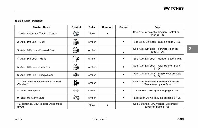
SWITCHES
Table 5 Dash Switches
Symbol Name Symbol Color Standard Option Page
1. Axle, Automatic Traction Control None ● See Axle, Automatic Traction Control onpage 3-106.
2. Axle, Diff-Lock - Dual Amber ● See Axle, Diff-Lock - Dual on page 3-106.
3. Axle, Diff-Lock - Forward Rear Amber●
See Axle, Diff-Lock - Forward Rear onpage 3-106.
4. Axle, Diff-Lock - Front Amber ● See Axle, Diff-Lock - Front on page 3-106.
5. Axle, Diff-Lock - Rear Rear Amber ● See Axle, Diff-Lock - Rear Rear on page3-106.
6. Axle, Diff-Lock - Single Rear Amber ● See Axle, Diff-Lock - Single Rear on page3-106.
7. Axle, Inter-Axle Differential Locked(Tandem) Amber ● See Axle, Inter-Axle Differential Locked
(Tandem) on page 3-46.
8. Axle, Two Speed Green ● See Axle, Two Speed on page 3-106.
9. Back Up Alarm Mute Amber ● See Back Up Alarm Mute on page 3-106.
10. Batteries, Low Voltage Disconnect(LVD) None ● See Batteries, Low Voltage Disconnect
(LVD) on page 3-106.
(03/17) Y53-1203-1E1 3-99
3
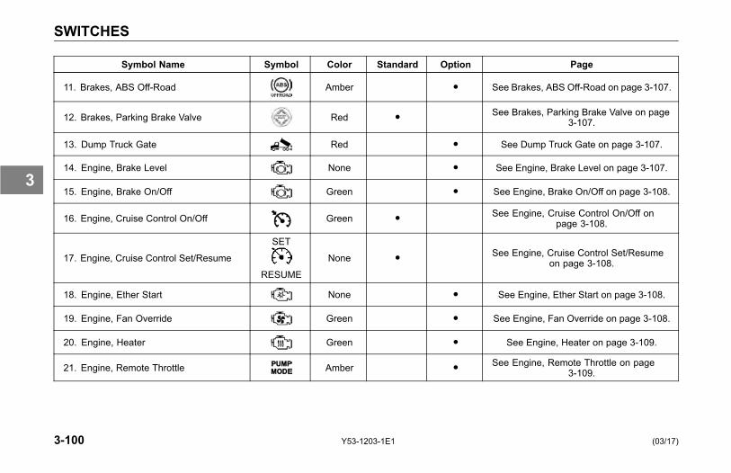
SWITCHES
Symbol Name Symbol Color Standard Option Page
11. Brakes, ABS Off-Road Amber ● See Brakes, ABS Off-Road on page 3-107.
12. Brakes, Parking Brake Valve Red ● See Brakes, Parking Brake Valve on page3-107.
13. Dump Truck Gate Red ● See Dump Truck Gate on page 3-107.
14. Engine, Brake Level None ● See Engine, Brake Level on page 3-107.
15. Engine, Brake On/Off Green ● See Engine, Brake On/Off on page 3-108.
16. Engine, Cruise Control On/Off Green ● See Engine, Cruise Control On/Off onpage 3-108.
17. Engine, Cruise Control Set/Resume
SET
RESUME
None ● See Engine, Cruise Control Set/Resumeon page 3-108.
18. Engine, Ether Start None ● See Engine, Ether Start on page 3-108.
19. Engine, Fan Override Green ● See Engine, Fan Override on page 3-108.
20. Engine, Heater Green ● See Engine, Heater on page 3-109.
21. Engine, Remote Throttle Amber ● See Engine, Remote Throttle on page3-109.
3-100 Y53-1203-1E1 (03/17)
3
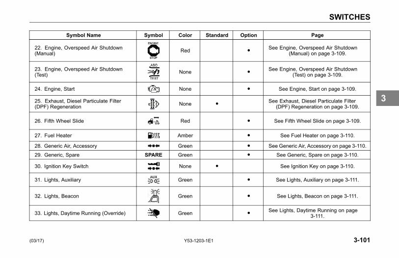
SWITCHES
Symbol Name Symbol Color Standard Option Page
22. Engine, Overspeed Air Shutdown(Manual) Red ● See Engine, Overspeed Air Shutdown
(Manual) on page 3-109.
23. Engine, Overspeed Air Shutdown(Test) None ● See Engine, Overspeed Air Shutdown
(Test) on page 3-109.
24. Engine, Start None ● See Engine, Start on page 3-109.
25. Exhaust, Diesel Particulate Filter(DPF) Regeneration None ● See Exhaust, Diesel Particulate Filter
(DPF) Regeneration on page 3-109.
26. Fifth Wheel Slide Red ● See Fifth Wheel Slide on page 3-109.
27. Fuel Heater Amber ● See Fuel Heater on page 3-110.
28. Generic Air, Accessory Green ● See Generic Air, Accessory on page 3-110.
29. Generic, Spare SPARE Green ● See Generic, Spare on page 3-110.
30. Ignition Key Switch None ● See Ignition Key on page 3-110.
31. Lights, Auxiliary Green ● See Lights, Auxiliary on page 3-111.
32. Lights, Beacon Green ● See Lights, Beacon on page 3-111.
33. Lights, Daytime Running (Override) Green ● See Lights, Daytime Running on page3-111.
(03/17) Y53-1203-1E1 3-101
3
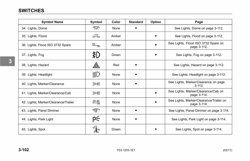
SWITCHES
Symbol Name Symbol Color Standard Option Page
34. Lights, Dome None ● See Lights, Dome on page 3-112.
35. Lights, Flood Amber ● See Lights, Flood on page 3-112.
36. Lights, Flood ISO 3732 Spare Amber ● See Lights, Flood ISO 3732 Spare onpage 3-112.
37. Lights, Fog Green ● See Lights, Fog on page 3-112.
38. Lights, Hazard Red ● See Lights, Hazard on page 3-112.
39. Lights, Headlight None ● See Lights, Headlight on page 3-112.
40. Lights, Marker/Clearance None ● See Lights, Marker/Clearance on page3-113.
41. Lights, Marker/Clearance/Cab None ● See Lights, Marker/Clearance/Cab onpage 3-114.
42. Lights, Marker/Clearance/Trailer None ● See Lights, Marker/Clearance/Trailer onpage 3-114.
43. Lights, Panel Dimmer None ● See Lights, Panel Dimmer on page 3-114.
44. Lights, Park Light None ● See Lights, Park Light on page 3-114.
45. Lights, Spot Green ● See Lights, Spot on page 3-114.
3-102 Y53-1203-1E1 (03/17)
3
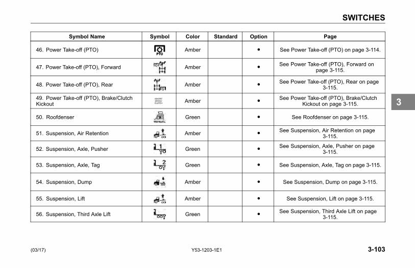
SWITCHES
Symbol Name Symbol Color Standard Option Page
46. Power Take-off (PTO) Amber ● See Power Take-off (PTO) on page 3-114.
47. Power Take-off (PTO), Forward Amber ● See Power Take-off (PTO), Forward onpage 3-115.
48. Power Take-off (PTO), Rear Amber ● See Power Take-off (PTO), Rear on page3-115.
49. Power Take-off (PTO), Brake/ClutchKickout Amber ● See Power Take-off (PTO), Brake/Clutch
Kickout on page 3-115.
50. Roofdenser Green ● See Roofdenser on page 3-115.
51. Suspension, Air Retention Amber ● See Suspension, Air Retention on page3-115.
52. Suspension, Axle, Pusher Green ● See Suspension, Axle, Pusher on page3-115.
53. Suspension, Axle, Tag Green ● See Suspension, Axle, Tag on page 3-115.
54. Suspension, Dump Amber ● See Suspension, Dump on page 3-115.
55. Suspension, Lift Amber ● See Suspension, Lift on page 3-115.
56. Suspension, Third Axle Lift Green ● See Suspension, Third Axle Lift on page3-115.
(03/17) Y53-1203-1E1 3-103
3
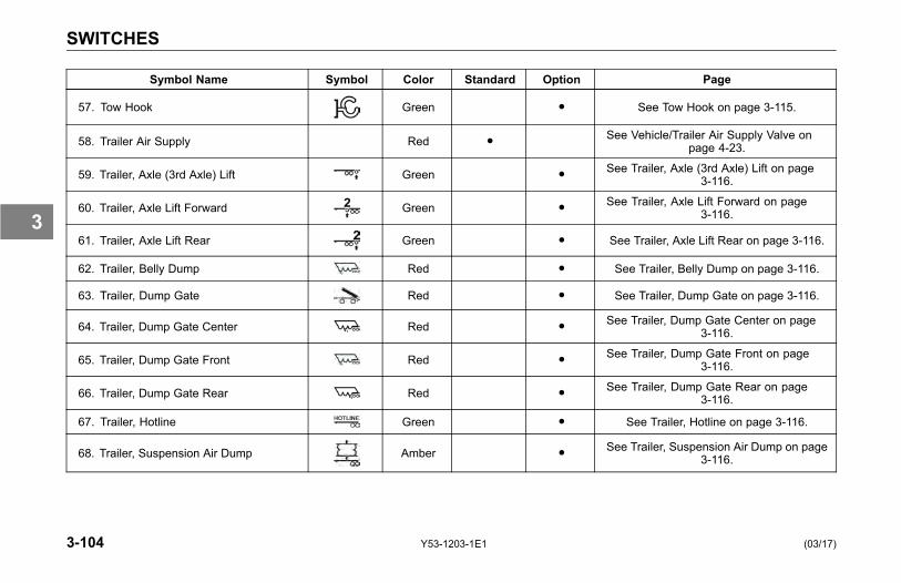
SWITCHES
Symbol Name Symbol Color Standard Option Page
57. Tow Hook Green ● See Tow Hook on page 3-115.
58. Trailer Air Supply Red ● See Vehicle/Trailer Air Supply Valve onpage 4-23.
59. Trailer, Axle (3rd Axle) Lift Green ● See Trailer, Axle (3rd Axle) Lift on page3-116.
60. Trailer, Axle Lift Forward Green ● See Trailer, Axle Lift Forward on page3-116.
61. Trailer, Axle Lift Rear Green ● See Trailer, Axle Lift Rear on page 3-116.
62. Trailer, Belly Dump Red ● See Trailer, Belly Dump on page 3-116.
63. Trailer, Dump Gate Red ● See Trailer, Dump Gate on page 3-116.
64. Trailer, Dump Gate Center Red ● See Trailer, Dump Gate Center on page3-116.
65. Trailer, Dump Gate Front Red ● See Trailer, Dump Gate Front on page3-116.
66. Trailer, Dump Gate Rear Red ● See Trailer, Dump Gate Rear on page3-116.
67. Trailer, Hotline Green ● See Trailer, Hotline on page 3-116.
68. Trailer, Suspension Air Dump Amber ● See Trailer, Suspension Air Dump on page3-116.
3-104 Y53-1203-1E1 (03/17)
3
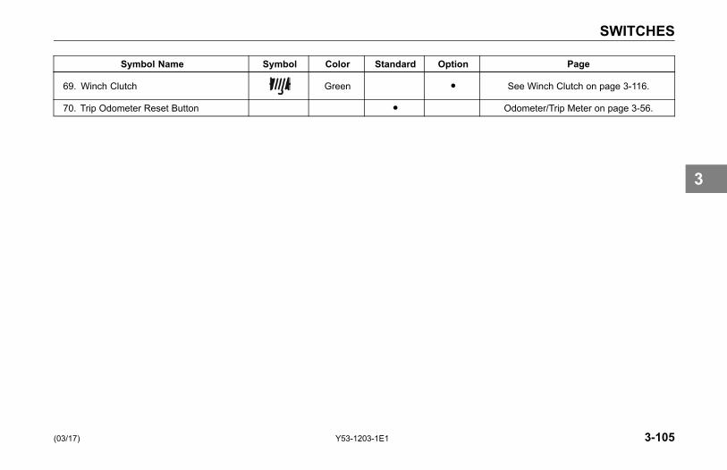
SWITCHES
Symbol Name Symbol Color Standard Option Page
69. Winch Clutch Green ● See Winch Clutch on page 3-116.
70. Trip Odometer Reset Button ● Odometer/Trip Meter on page 3-56.
(03/17) Y53-1203-1E1 3-105
3

SWITCHES
1. Axle, Automatic TractionControlMomentarily push switch in toengage Deep Mud and SnowTraction Control. See Deep Snowand Mud Switch on page 4-36.
2. Axle Diff-Lock - DualTurn switch on to engage Frontand Rear Axle Diff Lock.
3. Axle Diff-Lock - Forward RearTurn switch on to engage ForwardRear Axle Diff Lock.
4. Axle Diff Lock - FrontTurn switch on to engage FrontAxle Diff Lock.
5. Axle Diff-Lock Rear RearTurn switch on to engage RearRear Axle Diff Lock.
6. Axle Diff Lock - Single RearTurn switch on to engage SingleRear Axle Diff Lock.
7. Axle, Inter-Axle DifferentialLocked (Tandem)Turn switch on to engageInter-Axle Differential Lock.
8. Axle, Two SpeedIf equipped, the two speed axleswitch allows you to select axlehigh and low ranges. The lowrange (Off) provides maximumtorque for operating off-highway.The high range (On) is a fasterratio for highway speeds.
9. Back Up Alarm MuteTurn switch on to mute Back UpAlarm.
NOTEKenworth discourages the use of themute function. Only use mute whenlegally required.
10. Batteries, Low VoltageDisconnect (LVD)
If your vehicle is equipped with a LowVoltage Disconnect (LVD) feature,the LVD module is located inside thedriver's side kick panel.
NOTE86 in. Aerocab Sleepers have anadditional LVD located either behindthe sleeper fuse panel or inside thesleeper tool-box.
Purpose
The LVD may increase battery lifeand prevent unnecessary jumpstart conditions by ensuring that anunattended load does not depletethe battery charge to a level that willprevent you from starting your vehicle.
Operation
The LVD will disconnect non-vitalbattery loads when battery voltage
3-106 Y53-1203-1E1 (03/17)
3

SWITCHES
drops below 12.3V for 3 minutes andthe key switch is in the ACC or OFFposition. During the last 2 minutesthe LVD will emit a slow audible beep.30 seconds before disconnectingloads the alarm will change to a fastbeep. Turning the key switch to theON position at anytime will reconnectloads disconnected by the LVD.
See an authorized Kenworth Dealer ifthe LVD fails to reconnect loads duringnormal operation.
Circuits Disconnected by LVD
• Cab Dome Lamps
• Cab Accessories
• Spare Battery A & B
• Sleeper Dome Lamps
• Sleeper Accessories
NOTEAll LVD circuits are color-coded blueon the central electrical panel coverlabel.
WARNING!Do not use the Spare Battery A &B circuits or other circuits that arecontrolled by the LVD to power elec-tronic engine controls, ABS circuits,or safety/work-related lighting. Be-fore adding any device to the vehi-cle's electrical system, consult yournearest authorized Kenworth Dealeror read the contents of TMCRP-136.Failure to do so may cause equip-ment damage or lead to personal in-jury.
NOTEThe determination of what cir-cuits/loads that were connected tothe LVD was based upon the rec-ommendation from Technology andMaintenance Council (TMC) of theAmerican Trucking Association. Toreview the recommended practice,see TMC RP-136.
11. Brakes, ABS Off-RoadTurn switch on to engage ABSOff-Road mode. See Anti-LockBraking System on page 3-36.
12. Brakes, Parking Brake ValvePull yellow knob to activate parkingbrakes. See Parking Brake Valveon page 3-107.
13. Dump Truck GateTurn switch on to open DumpTruck Gate.
(03/17) Y53-1203-1E1 3-107
3
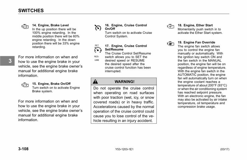
SWITCHES
14. Engine, Brake LevelIn the up position there will be100% engine retarding. In themiddle position there will be 60%engine retarding. In the downposition there will be 33% engineretarding.
For more information on when andhow to use the engine brake in yourvehicle, see the engine brake owner’smanual for additional engine brakeinformation.
15. Engine, Brake On/OffTurn switch on to activate EngineBrake system.
For more information on when andhow to use the engine brake in yourvehicle, see the engine brake owner’smanual for additional engine brakeinformation.
16. Engine, Cruise ControlOn/OffTurn switch on to activate CruiseControl System.
SET
RES-
UME
17. Engine, Cruise ControlSet/ResumeThe Cruise Control Set/Resumeswitch allows you to SET thedesired speed or RESUMEthe desired speed after thecruise control function has beeninterrupted.
WARNING!Do not operate the cruise controlwhen operating on road surfaceswith poor traction (wet, icy, or snowcovered roads) or in heavy traffic.Accelerations caused by the normaloperation of the cruise control couldcause you to lose control of the ve-hicle resulting in an injury accident.
18. Engine, Ether StartMomentarily push switch in toactivate the Ether Start system.
19. Engine Fan OverrideThe engine fan switch allowsyou to control the engine fanmanually or automatically. Withthe ignition key switch ON andthe fan switch in the MANUALposition, the engine fan will be onregardless of engine temperature.With the engine fan switch in theAUTOMATIC position, the enginefan will automatically turn on whenthe engine coolant reaches atemperature of about 200°F (93°C)or when the air conditioning systemhas reached setpoint pressure.With an electronic engine, the fanmay also be activated by air intaketemperature, oil temperature andcompression brake usage.
3-108 Y53-1203-1E1 (03/17)
3
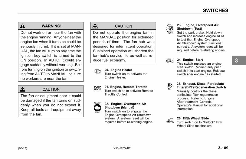
SWITCHES
WARNING!Do not work on or near the fan withthe engine running. Anyone near theengine fan when it turns on could beseriously injured. If it is set at MAN-UAL, the fan will turn on any time theignition key switch is turned to theON position. In AUTO, it could en-gage suddenly without warning. Be-fore turning on the ignition or switch-ing from AUTO to MANUAL, be sureno workers are near the fan.
CAUTIONThe fan or equipment near it couldbe damaged if the fan turns on sud-denly when you do not expect it.Keep all tools and equipment awayfrom the fan.
CAUTIONDo not operate the engine fan inthe MANUAL position for extendedperiods of time. The fan hub wasdesigned for intermittent operation.Sustained operation will shorten thefan hub’s service life as well as re-duce fuel economy.
20. Engine HeaterTurn switch on to activate theEngine Heater.
21. Engine, Remote ThrottleTurn switch on to activate RemoteThrottle Control.
22. Engine, Overspeed AirShutdown (Manual)Turn switch on to engage theEngine Overspeed Air Shutdownsystem. A system reset will berequired before re-starting engine.
23. Engine, Overspeed AirShutdown (Test)Set the park brake. Hold downswitch and increase engine RPMto test that Engine OverspeedAir Shutdown system functionscorrectly. A system reset will berequired before re-starting engine.
24. Engine, StartThis switch replaces an enginestart switch. Momentarily pushswitch in to start engine. Releaseswitch after engine has started.
25. Exhaust, Diesel ParticulateFilter (DPF) Regeneration SwitchManually controls the dieselparticulate filter regenerationprocess. Refer to EngineAfter-treatment ControlsOperator's Manual for additionalinformation.
26. Fifth Wheel SlideTurn switch on to "Unlock" FifthWheel Slide mechanism.
(03/17) Y53-1203-1E1 3-109
3

SWITCHES
NOTEVehicles having an air slide fifthwheel have a fifth wheel slider lockcontrolled by a switch on the instru-ment panel. By placing the switchin the unlock position you can slidethe fifth wheel to various positionsto adjust weight distribution.
The switch is guarded to protectyou from accidentally activating orreleasing the lock.
WARNING!Do not move the fifth wheel while thetractor-trailer is in motion. Your loadcould shift suddenly, causing you tolose control of the vehicle. Neveroperate the vehicle with the switchin the UNLOCK position. Always in-spect the fifth wheel after you lockthe switch to be sure the fifth wheelslide lock is engaged. Failure tocomply may result in personal injury,death, equipment or property dam-age.
27. Fuel HeaterTurn switch on to activate FuelHeater.
28. Generic, Air, AccessoryProvides accessory air to the endof frame connection when switchis turned on.
SP-ARE
29. Generic, SpareTurn switch on to power customerinstalled accessory.
30. Ignition Key Switch
The ignition key switch (located to theleft of the steering column) has fourpositions: ACC (Accessories), OFF,ON, and START.
OFF: In this position all accessoriesare OFF (except those listed below)and you can remove the key.
• The following lights andaccessories have power when thekey is in the OFF position:
° brake lights
° emergency hazard flasher
° dome and courtesy lamps (ondoors)
3-110 Y53-1203-1E1 (03/17)
3
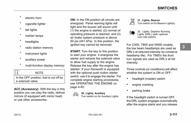
SWITCHES
° electric horn
° cigarette lighter
° tail lights
° marker lamps
° headlights
° radio station memory
° instrument lights
° auxiliary power
° multi-function display memory
NOTEIn the OFF position, fuel is cut off bya solenoid valve.
ACC (Accessory): With the key in thisposition you can play the radio, defrostmirrors (if equipped with mirror heat)or use other accessories.
ON: In the ON position all circuits areenergized. Panel warning lights willlight and the buzzer will sound until(1) the engine is started, (2) normal oiloperating pressure is reached, and (3)air brake system pressure is above64 psi (441 kPa). In this position, theignition key cannot be removed.
START: Turn the key to this positionto start your engine: it energizes thestarter and retracts the solenoid valveto allow fuel supply to the engine.Release the key after the engine hasstarted. If your Kenworth is equippedwith the optional push button starterswitch, use it to engage the starter. Forcomplete engine starting procedures,see OPERATING THE ENGINE onpage 4-45.
30. Lights, AuxiliaryTurn switch on for Auxiliary Lights.
31. Lights, BeaconTurn switch on for Beacon Light(s).
32. Lights, Daytime RunningLights (DRL) (with optionalover-ride switch)
For C500, T800 and W900 models,the low beam headlamps are used asDRL’s at reduced intensity (to conserveheadlamp life). For T660's the frontturn signals are used as DRL’s at fullintensity.
Three controls (or conditions) will affectwhether the system is ON or OFF:
• headlight (master) switch
• engine cranking
• parking brake
If the headlight switch is turned OFF,the DRL system engages automaticallyafter the engine starts and you release
(03/17) Y53-1203-1E1 3-111
3
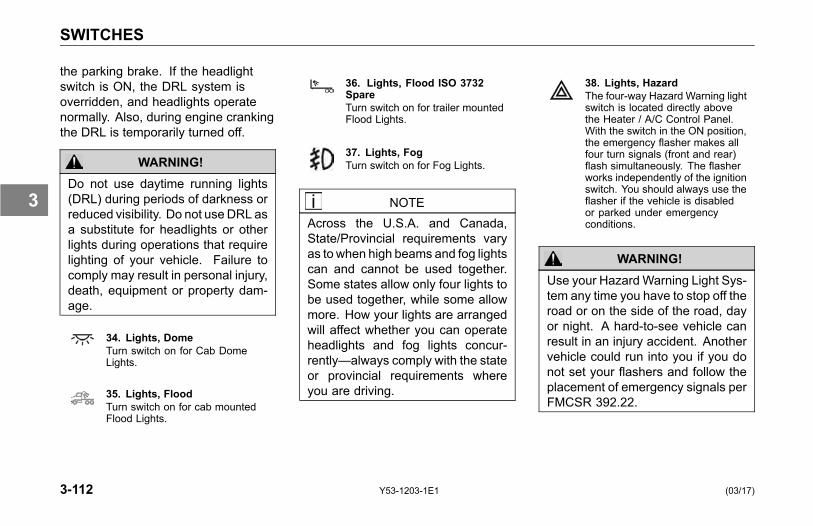
SWITCHES
the parking brake. If the headlightswitch is ON, the DRL system isoverridden, and headlights operatenormally. Also, during engine crankingthe DRL is temporarily turned off.
WARNING!Do not use daytime running lights(DRL) during periods of darkness orreduced visibility. Do not useDRL asa substitute for headlights or otherlights during operations that requirelighting of your vehicle. Failure tocomply may result in personal injury,death, equipment or property dam-age.
34. Lights, DomeTurn switch on for Cab DomeLights.
35. Lights, FloodTurn switch on for cab mountedFlood Lights.
36. Lights, Flood ISO 3732SpareTurn switch on for trailer mountedFlood Lights.
37. Lights, FogTurn switch on for Fog Lights.
NOTEAcross the U.S.A. and Canada,State/Provincial requirements varyas to when high beams and fog lightscan and cannot be used together.Some states allow only four lights tobe used together, while some allowmore. How your lights are arrangedwill affect whether you can operateheadlights and fog lights concur-rently—always comply with the stateor provincial requirements whereyou are driving.
38. Lights, HazardThe four-way Hazard Warning lightswitch is located directly abovethe Heater / A/C Control Panel.With the switch in the ON position,the emergency flasher makes allfour turn signals (front and rear)flash simultaneously. The flasherworks independently of the ignitionswitch. You should always use theflasher if the vehicle is disabledor parked under emergencyconditions.
WARNING!Use your HazardWarning Light Sys-tem any time you have to stop off theroad or on the side of the road, dayor night. A hard-to-see vehicle canresult in an injury accident. Anothervehicle could run into you if you donot set your flashers and follow theplacement of emergency signals perFMCSR 392.22.
3-112 Y53-1203-1E1 (03/17)
3

SWITCHES
39. Lights, HeadlightTurn switch on for headlights.When the Headlights are ON, thedash lights, side, and tail lights arealso on.
Your Kenworth vehicle uses anelectronic control unit to interfacelighting functions from the dashswitches and turn signal stalk to theturn/stop lamps on the vehicle andturn signals only on the trailer. Thiselectronic unit has control functionsdesigned to protect the system fromfailures and keep your exterior lightingsystem operating reliably.
In the event the vehicle's lightingsystem defaults to protection mode,follow the steps below to assist indetermining the lighting system'scondition.
NOTEStop your vehicle before diagnosingthe system.
Switch Position: Headlamps On, LowBeam Selected
Symptom: High beam indicator lampin dash is illuminated. Headlampsmomentarily flashed several times, butotherwise appear to operate okay.
Cause: The electronic control unithas detected a short in the right orleft low beam wiring circuit. Underthis condition, the system controllerautomatically activates the highbeams, but the headlamps operate ata reduced intensity. After 1 secondof detecting a fault, the control unitwill attempt to activate the low beamheadlamps again. If the fault isnot cleared after five attempts, theheadlamps will remain on high beam(reduced intensity) until the headlampswitch is turned off.
Correction: Check both low beamheadlamp fuses in the powerdistribution box.
• If you find a blown fuse, replace itwith the same amperage fuse andtry the headlamps again.
• If the fuse continues to blow,contact your nearest Kenworthdealer for service.
CAUTIONIf you have confirmed there is aproblem in the low beam wiring cir-cuit, proceed with caution to thenext available exit/turnoff and safelypull your vehicle completely off theroad and call for assistance. Driv-ing your vehicle with the headlampson high beam (at reduced intensity)for a prolonged period could leadto an injury accident. Contact yournearest Kenworth dealer to havethe problem corrected as soon aspossible.
40. Lights, Marker/ClearanceTurn switch on to control Cab andVehicle Marker/Clearance lights.
(03/17) Y53-1203-1E1 3-113
3

SWITCHES
A separate switch next to the headlightswitch turns on the marker lights forboth the cab and trailer. These arethe five amber lights on top of thecab, front trailer lights, and red reartruck/trailer lights.
NOTEAn interrupt switch for the trailermarker lights is mounted on the endof the turn signal lever.
41. Lights, Marker/Clearance/CabTurn switch on to controlCab Marker/Clearance lightsseparately from the trailer.
42. Lights, Marker/Clearance/TrailerTurn switch on to controlTrailer Marker/Clearance lightsseparately from the vehiclemarker/clearance lights.
43. Lights, Panel DimmerRotate thumb wheel up to brightenpanel lights. Rotate thumb wheeldown to dim panel lights.
NOTEThe Headlight Switch must be in oneof two ON positions for the panellights to operate.
44. Lights, Park LightTurn switch on for Park Lights.When the Park Lights are on thedash lights, side and tail lights arealso on.
45. Lights, SpotTurn switch on for Spot Light.
46. Power Take-off (PTO)Turn switch on to engage PTO.
Your Kenworth vehicle may beequipped with a dash mountedair switch that controls PTOengagement/disengagement.
When the operator activates the switchfor the PTO, the status indicatorlamp (located on the switch) willimmediately illuminate even thoughPTO engagement may not haveoccurred.
If the PTO is engaged and the operatorturns the switch OFF, the PTO statusindicator lamp (located on the switch)will go out immediately even thoughPTO disengagement may not haveoccurred.
NOTEDo not drive vehicle with PTO en-gaged.
NOTEActual PTO engagement / disen-gagement may be delayed momen-tarily since it is controlled by the airsystem and mechanical movement.
3-114 Y53-1203-1E1 (03/17)
3

SWITCHES
CAUTIONIncreasing engine RPM before thePTO is actually engaged could pre-vent the PTO from engaging and/orcause PTO damage.
47. Power Take-off (PTO),ForwardTurn switch on to engage forwardPTO.
48. Power Take-off (PTO), RearTurn switch on to engage RearPTO.
49. Power Take-off (PTO),Brake/Clutch KickoutTurn switch on to disable PTOwhen brake pedal or clutch pedalare depressed.
50. RoofdenserTurn switch on for roof mountedcondenser fan.
51. Suspension, Air RetentionThe Air Retention Switch keepsthe air suspension bags fromlosing air pressure when usedwith vehicle outriggers. Depressthe Air Retention Switch prior todeploying the outriggers. Whileoutriggers are deployed axlestability is maintained.
52. Suspension, Axle, PusherTurn switch on to lower Single orForward Pusher Axle.
53. Suspension, Axle, TagTurn switch on to lower tag axle.
54. Suspension, DumpTurn switch on to deflatesuspension air bags. Theswitch is guarded to protect youfrom accidentally deflating thesuspension.
WARNING!Do not operate the Air SuspensionDeflate Switch (Dump Valve) whiledriving. Sudden deflation while yourvehicle is moving can affect han-dling and control. Failure to complymay result in personal injury, death,equipment or property damage.
CAUTIONOperating a vehicle with air suspen-sion bags either overinflated or un-derinflated may cause damage todriveline components. If a vehiclemust be operated under such condi-tions, do not exceed 5 mph (8 km/h).
55. Suspension, LiftTurn switch on to over-inflatesuspension air bags. Turn switchoff for normal suspension height.
56. Suspension Third Axle LiftTurn switch on to raise Third Axle.
(03/17) Y53-1203-1E1 3-115
3

SWITCHES
57. Tow HookTurn switch on to remove the slackfrom the Tow Hook.
58. Trailer Air SupplyThe red octagon knob controls theair supply to the trailer.
59. Trailer, Axle (3rd Axle) LiftTurn switch on to lift 3rd TrailerAxle.
60. Trailer, Axle Lift ForwardTurn switch on to lift ForwardTrailer Axle.
61. Trailer, Axle Lift RearTurn switch on to lift Rear TrailerAxle.
62. Trailer, Belly DumpTurn switch on to open TrailerBelly Dump.
63. Trailer Dump GateTurn switch on to open TrailerDump Gate.
64. Trailer, Dump Gate CenterTurn switch on to open TrailerCenter Dump Gate.
65. Trailer, Dump Gate FrontTurn switch on to open TrailerFront Dump Gate.
66. Trailer, Dump Gate RearTurn switch on to open TrailerRear Dump Gate.
67. Trailer HotlineTurn switch on to supply electricalpower to trailer accessories.
68. Trailer, Suspension AirDumpTurn switch on to deflate TrailerAir Suspension.
69. Winch ClutchTurn switch on to engage WinchClutch.
3-116 Y53-1203-1E1 (03/17)
3
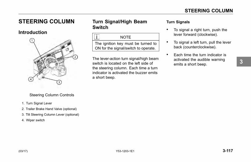
STEERING COLUMN
STEERING COLUMN
Introduction
Steering Column Controls
1. Turn Signal Lever
2. Trailer Brake Hand Valve (optional)
3. Tilt Steering Column Lever (optional)
4. Wiper switch
Turn Signal/High BeamSwitch
NOTEThe ignition key must be turned toON for the signal/switch to operate.
The lever-action turn signal/high beamswitch is located on the left side ofthe steering column. Each time a turnindicator is activated the buzzer emitsa short beep.
Turn Signals
• To signal a right turn, push thelever forward (clockwise).
• To signal a left turn, pull the leverback (counterclockwise).
• Each time the turn indicator isactivated the audible warningemits a short beep.
(03/17) Y53-1203-1E1 3-117
3
STEERING COLUMN
NOTEIf the vehicle turn signals and turnsignal indicators in the dash gaugecluster ever begin flashing at anaccelerated rate (115 cycles perminute) when the turn signal leveris in the OFF (center) position, orwhen a Right/Left turn has been se-lected, the problem may be relatedto a failed turn signal switch or turnsignal module. In either case, theproblem is not a failed bulb. Contactyour nearest authorized KenworthDealer to have the problem cor-rected as soon as possible.
CAUTIONAfter you complete a turn, shutthe system off by returning thelever to the "OFF" (center) position.The switch's lever action is NOTself-canceling. Failure to shut offa turn signal could confuse otherdrivers and result in an injury ac-cident. An indicator light in theinstrument panel will flash until theturn signal is turned off.
High Beam
NOTEThe headlights must be ON for thehigh beam switch to operate.
• To switch your headlights to loweror higher beam, gently pull the turnsignal lever, toward the steeringwheel, until you hear the switchclick and the beam changes.The blue indicator light in theinstrument panel will be ON whenthe high beam is being used.
• To return to previous beam: pullthe lever towards the steeringwheel again.
• To momentarily flash yourheadlights (illuminating thehigh-beams), push the turn signallever forward.
3-118 Y53-1203-1E1 (03/17)
3

STEERING COLUMN
NOTE• You cannot momentarily flash
headlights when high beams areon. The headlights will flash onif they are off, if headlamps areon as low beams, headlampsdim to 25%.
• Headlight flash is not availableon models with high intensitydischarge (HID) headlight option.
• Check your local state’sregulations for any restrictionon the use of the high-beamflashing function.
Windshield Wipers/Washer
Your Kenworth is equipped with atwo-speed, intermittent windshieldwiper system. A seven-position rotarywiper switch (located on the turn-signallever) operates the windshield wipersand washer. Rotate the end of the turnsignal lever to change the wiper mode.
NOTEThe ignition key must be turned toON or ACC for the wiper/washerswitches to operate.
1 Press in for washer pump2 Rotate to change wiper
mode3 Press button for Marker / ID
Lamp flash
The first position after OFF is theintermittent #1 cycle. The nextpositions are intermittent #2, #3 and#4. The last two positions are wiperlow speed and wiper high speed. Seethe wiper switch settings table forintermittent delay times.
NOTEThe ignition key must be turned toON or ACC for the wiper/washerswitch to operate.
(03/17) Y53-1203-1E1 3-119
3
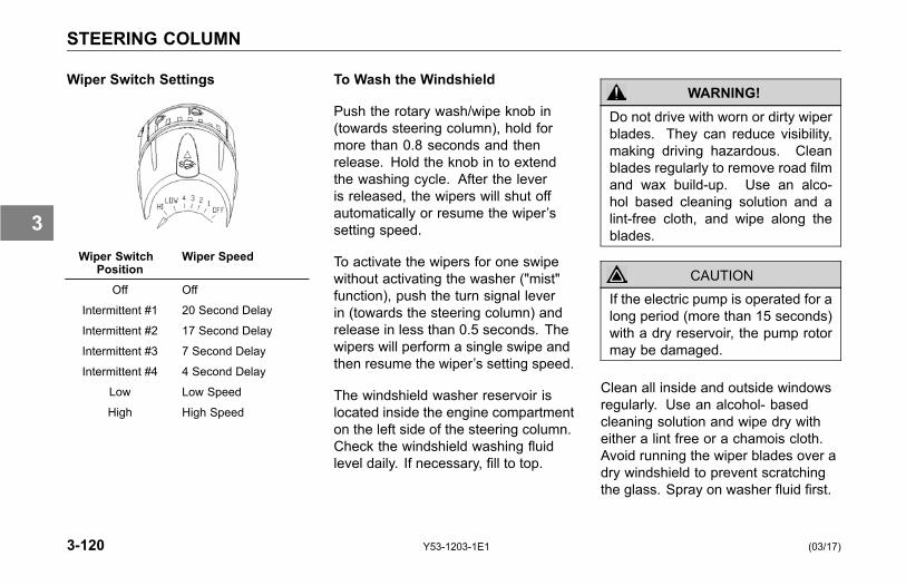
STEERING COLUMN
Wiper Switch Settings
Wiper SwitchPosition
Wiper Speed
Off Off
Intermittent #1 20 Second Delay
Intermittent #2 17 Second Delay
Intermittent #3 7 Second Delay
Intermittent #4 4 Second Delay
Low Low Speed
High High Speed
To Wash the Windshield
Push the rotary wash/wipe knob in(towards steering column), hold formore than 0.8 seconds and thenrelease. Hold the knob in to extendthe washing cycle. After the leveris released, the wipers will shut offautomatically or resume the wiper’ssetting speed.
To activate the wipers for one swipewithout activating the washer ("mist"function), push the turn signal leverin (towards the steering column) andrelease in less than 0.5 seconds. Thewipers will perform a single swipe andthen resume the wiper’s setting speed.
The windshield washer reservoir islocated inside the engine compartmenton the left side of the steering column.Check the windshield washing fluidlevel daily. If necessary, fill to top.
WARNING!Do not drive with worn or dirty wiperblades. They can reduce visibility,making driving hazardous. Cleanblades regularly to remove road filmand wax build-up. Use an alco-hol based cleaning solution and alint-free cloth, and wipe along theblades.
CAUTIONIf the electric pump is operated for along period (more than 15 seconds)with a dry reservoir, the pump rotormay be damaged.
Clean all inside and outside windowsregularly. Use an alcohol- basedcleaning solution and wipe dry witheither a lint free or a chamois cloth.Avoid running the wiper blades over adry windshield to prevent scratchingthe glass. Spray on washer fluid first.
3-120 Y53-1203-1E1 (03/17)
3

STEERING COLUMN
Trailer Brake Hand Valve
This hand valve, mounted on thesteering wheel column, provides airpressure to apply the trailer brakesonly. It operates independently ofthe foot treadle valve. See Using theBrake System on page 4-16, for moreinstructions on proper use of the TrailerBrake Hand Valve.
Stop/Turn Signal LampOperation
Your Kenworth vehicle uses combinedstop/turn signal lamps at the rear ofthe vehicle, using the same bulb toperform both functions. This means asingle bulb is used for the brake lampas well as the turn signal lamp. Thisbulb will burn steadily with the brakesapplied. The same bulb will flash withthe turn signal activated, even with thebrakes applied.
Maximum Number of LampsAllowed per Circuit
• Vehicle Stop/Turn Signal Circuit
The lighting control unit is limitedto 5 amps total, or two (2) 25 wattincandescent bulbs per side. Do notwire more than two incandescent bulbsper side to the vehicle tail lamp fixtures.If more than two bulbs are requiredfor each tail lamp fixture, install LEDtype lamps, or contact your nearestKenworth dealer for other options.
• Trailer Turn and Vehicle ForwardSide Facing Turn Lamp Circuit
The lighting control unit is limitedto 20 amps or nine (9) 25 wattincandescent bulbs total (per side) forthe combination of trailer turn lampsand vehicle forward side facing turnlamps. Do not wire more than nineincandescent bulbs per side for thecombination of trailer turn lamps andvehicle forward side facing turn lamps.
(03/17) Y53-1203-1E1 3-121
3

STEERING COLUMN
If more than nine bulbs per side arerequired, install LED type lamps, orcontact your nearest Kenworth dealerfor other options.
CAUTIONBefore installing additional vehiclestop/turn lamps, trailer turn lamps oradditional forward side facing turnlamps on the vehicle, make sure thelighting circuit limits described aboveare not exceeded. Exceeding thenumber of lamps designated abovecan/will cause the electronic controlunit to default to a protection mode,causing the lamps to not functionproperly.
Similar to the headlamp system, if aproblem is detected with the electroniccontrol unit, the control unit will cyclethe turn signals off once every 9seconds. You can detect that this isoccurring if the turn signal indicatorsin the dash operate intermittently. If
you experience intermittent turn signaloperation, the problem is either ashort in the turn signal circuit or themaximum number of bulbs has beenexceeded for the circuit.
If you experience any vehicle stop/turnsignal issues, contact your nearestKenworth dealer.
Adjustable Tilt/TelescopingColumn
The Adjustable Tilt/TelescopingColumn is an option on yourKenworth. Depending on yourvehicle’s configuration, you mayhave a Tilt/Telescoping steeringcolumn or Fixed steering column.The tilt feature allows forward andrearward movement of the wheel.The telescoping feature allows youto move the wheel up and down. Toactivate these features, locate theTilt/Telescoping pedal at the base ofthe steering column.
3-122 Y53-1203-1E1 (03/17)
3

STEERING COLUMN
WARNING!Do not adjust the Tilt-TelescopingSteering Wheel while the vehicle isin motion, it could cause loss of con-trol. You would not be able to steerproperly and could have an acci-dent. Make all adjustments to thesteering column while the vehicle isstopped. Failure to comply may re-sult in personal injury, death, equip-ment or property damage.
To tilt, raise or lower the Telescopingsteering wheel:
• Push the pedal down fully. Movethe wheel to the desired heightand angle, then release the pedalto lock the wheel at the desiredposition.
1 Tilt / Telescoping SteeringColumn Lever (optional)
Horn
Your vehicle may be equipped withair horns. To operate, pull on thelanyard extending from the overheadheader panel. Your vehicle may alsohave an electric horn. To sound theelectric horn, press the button in thecenter of the steering wheel, whichis the standard location for electrichorns (optional horn locations may berequested).
(03/17) Y53-1203-1E1 3-123
3
STEERING COLUMN
SmartWheel MultiplexControl System
CAUTIONUnder no circumstances shouldyou attempt to service the steeringwheel, clockspring, or any of theelectrical wiring in the multiplex sys-tem, or any steering components(steering column, steering drivelineor steering gear). Tampering withthese components may result in aninoperable multiplex system.
System Description
The multiplex steering wheel systemconsists of the steering wheel mountedcontrols, the multiplex electronicsmodule, the clockspring in the steeringcolumn and the interconnecting wireharnesses.
The steering wheel mounted controlstell the multiplex electronics module(located behind the dash) whichelectrical circuit to turn on or off.The controls are connected to theelectronics module with two wires,using a "multiplexed" electronic signal.This multiplexed signal allows morethan one switch to use the same pairof wires.
The multiplex electronics modulecontains relays and electronics toactivate the circuits controlled by thesteering wheel controls. These relaysare not replaceable. The relays thatcontrol the headlights, marker lights
and horn are still located in the truckpower distribution box. The electronicsmodule is located between the dashswitches and the relays, so that it cancontrol them.
The clockspring in the steeringcolumn is a rotating electrical contactcontaining a wound electrical ribbonthat lets "multiplexed" electrical signalsto get from the steering wheel hubto the electronics module and stillallow the steering wheel to turn. Theclockspring is located at the top of thesteering column directly beneath thesteering wheel.
3-124 Y53-1203-1E1 (03/17)
3
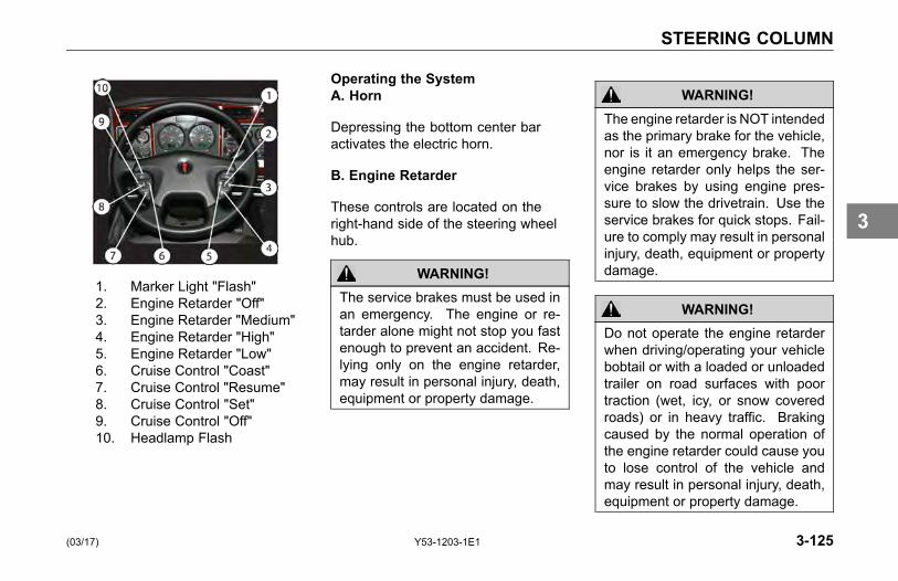
STEERING COLUMN
1. Marker Light "Flash"2. Engine Retarder "Off"3. Engine Retarder "Medium"4. Engine Retarder "High"5. Engine Retarder "Low"6. Cruise Control "Coast"7. Cruise Control "Resume"8. Cruise Control "Set"9. Cruise Control "Off"10. Headlamp Flash
Operating the SystemA. Horn
Depressing the bottom center baractivates the electric horn.
B. Engine Retarder
These controls are located on theright-hand side of the steering wheelhub.
WARNING!The service brakes must be used inan emergency. The engine or re-tarder alone might not stop you fastenough to prevent an accident. Re-lying only on the engine retarder,may result in personal injury, death,equipment or property damage.
WARNING!The engine retarder is NOT intendedas the primary brake for the vehicle,nor is it an emergency brake. Theengine retarder only helps the ser-vice brakes by using engine pres-sure to slow the drivetrain. Use theservice brakes for quick stops. Fail-ure to comply may result in personalinjury, death, equipment or propertydamage.
WARNING!Do not operate the engine retarderwhen driving/operating your vehiclebobtail or with a loaded or unloadedtrailer on road surfaces with poortraction (wet, icy, or snow coveredroads) or in heavy traffic. Brakingcaused by the normal operation ofthe engine retarder could cause youto lose control of the vehicle andmay result in personal injury, death,equipment or property damage.
(03/17) Y53-1203-1E1 3-125
3

STEERING COLUMN
NOTEThe exhaust brake and engine brakeare two types of engine retarders.Refer also to the Engine Manufac-turer’s Operator Manual and to theEngine Retarder manual for addi-tional instructions.
• To Activate:To activate the desired engineretarder setting:
Press for LOW.
Press for MEDIUM.
Press for HIGH.
NOTEYour engine may only have 2 engineretarder settings, LOW and HIGH.If so, the MEDIUM button is non-operational.
• To Turn Off:
Press for OFF.
C. Cruise Control
These controls are located on theleft-hand side of the steering wheelhub.
WARNING!Do not operate the cruise controlwhen operating on road surfaceswith poor traction (wet, icy, or snowcovered roads) or in heavy traffic.Accelerations caused by the normaloperation of the cruise control couldcause you to lose control of the ve-hicle resulting in an injury accident.
3-126 Y53-1203-1E1 (03/17)
3
STEERING COLUMN
• To Turn On:
Press the ON button.
• To Turn Off:
Press the OFF button. Any previousspeed settings are cleared.
Using Cruise Control While Driving
Setting Cruise Speed
1. Ensure that the vehicle speed isabove the minimum cruise controlspeed and the engine speed isabove 1100 rpm.
2. Press the "ON" button.
3. Accelerate the vehicle to thedesired cruise speed.
4. Press the "SET" button to set thecruise speed.
NOTECruise Control may not hold the setspeed going down hills. If the speedincreases going down a hill, use thebrakes to slow down. This will can-cel Cruise Control.
Changing the Cruise Set Speed
• To increase the cruise set speed:
Press the "SET" button until thedesired speed is achieved, thenrelease the button.
• To decrease the cruise set speed:
Press the "RESUME" button andcoast to the desired lower speed, thenrelease the button.
Cancelling Cruise Control
You can cancel cruise control in anyof these ways:
• Tap the brake pedal.
• Tap the clutch pedal.
• Press the "OFF" button.
Resuming Cruise Control
1. If you tapped the brake orclutch pedal, the cruise controlremembered the previously setcruise speed. To resume thatset speed, accelerate above theminimum cruise control speed andpress the "RESUME" button.
2. If you pressed the "OFF" button orturned the ignition key OFF, thiscleared the system memory andyou will need to set a new cruisespeed.
(03/17) Y53-1203-1E1 3-127
3

STEERING COLUMN
Using Cruise Control for StationaryPTO Operation
Setting Idle Speed
1. Ensure parking brakes are applied.
2. Ensure transmission is in Neutral.
3. Engage PTO per themanufacturer's operatinginstructions.
4. Press the "ON" button.
5. Press the "SET" button to obtainthe desired engine rpm.
Cancelling Cruise Control
You can cancel cruise control in anyof these ways:
• Tap the brake pedal.
• Tap the clutch pedal.
• Press the "OFF" button.
D. Headlight/Marker Lamp Flash
• Headlight Flash:
Press located on the upperleft corner of thesteering wheel hub.The headlights willflash on if they are off,if headlamps are on aslow beams, headlampsdim to 25%. Thisfunction is disabledon T660 with HIDheadlamp option. Ifheadlamps are on highbeams, high beams aredeactivated, low beamsare lit 25%. Headlampsreturn to low beam, nothigh beam.
• Marker Lamp Flash:
Press to flash on the markerlamps if they are off,or blink off if they areon while the button isheld down. This featureworks with the markerlamp switch on thedash in either position.The button controls thetrailer marker lamps(and the tractor markerlamps if they are on thesame switch).
3-128 Y53-1203-1E1 (03/17)
3
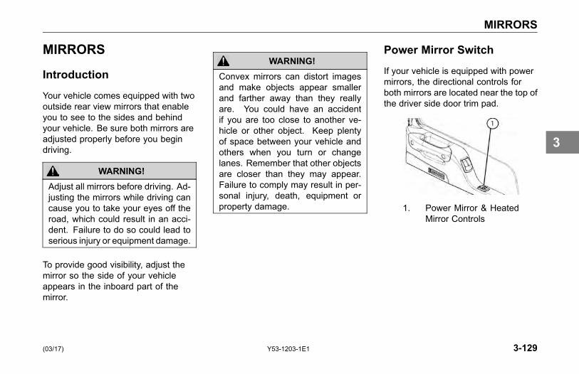
MIRRORS
MIRRORS
Introduction
Your vehicle comes equipped with twooutside rear view mirrors that enableyou to see to the sides and behindyour vehicle. Be sure both mirrors areadjusted properly before you begindriving.
WARNING!Adjust all mirrors before driving. Ad-justing the mirrors while driving cancause you to take your eyes off theroad, which could result in an acci-dent. Failure to do so could lead toserious injury or equipment damage.
To provide good visibility, adjust themirror so the side of your vehicleappears in the inboard part of themirror.
WARNING!Convex mirrors can distort imagesand make objects appear smallerand farther away than they reallyare. You could have an accidentif you are too close to another ve-hicle or other object. Keep plentyof space between your vehicle andothers when you turn or changelanes. Remember that other objectsare closer than they may appear.Failure to comply may result in per-sonal injury, death, equipment orproperty damage.
Power Mirror Switch
If your vehicle is equipped with powermirrors, the directional controls forboth mirrors are located near the top ofthe driver side door trim pad.
1. Power Mirror & HeatedMirror Controls
(03/17) Y53-1203-1E1 3-129
3

MIRRORS
1. Mirror Directional ControlPad
2. Mirror Selector Switch
To Adjust Kenworth AerodynamicStyle Mirrors
1. Move the mirror selector switchto the right or left from the neutralcenter position to select thedesired mirror for adjustment.
2. Depress the mirror directionalcontrol pad in one of its four arrowdirections to adjust the mirrorin/out or up/down.
NOTEAfter mirror adjustments have beencompleted, return the mirror selec-tor switch back to the center (neu-tral) position to prevent unintentionaladjustments to the mirrors.
To Adjust Moto Mirrors
1. For in/out mirror adjustment: Movethe mirror selector switch to theright or left from the neutral centerposition to select the desiredmirror for adjustment.
NOTEIf the mirror is fixed (non-motorized)on the left side, then the mirror selec-tor switch will ONLY allow selectionof the neutral and right mirror switchpositions.
2. Depress the mirror directionalcontrol pad towards the arrowspointing left or right to adjust themirror in/out.
NOTEBecause the Moto mirrors have only2- way adjustment, the mirror direc-tional control pad is also restricted inits movement to left or right ONLY.
NOTEAfter mirror adjustments have beencompleted, return the mirror selec-tor switch back to the center (neu-tral) position to prevent unintentionaladjustments to the mirrors.
3-130 Y53-1203-1E1 (03/17)
3
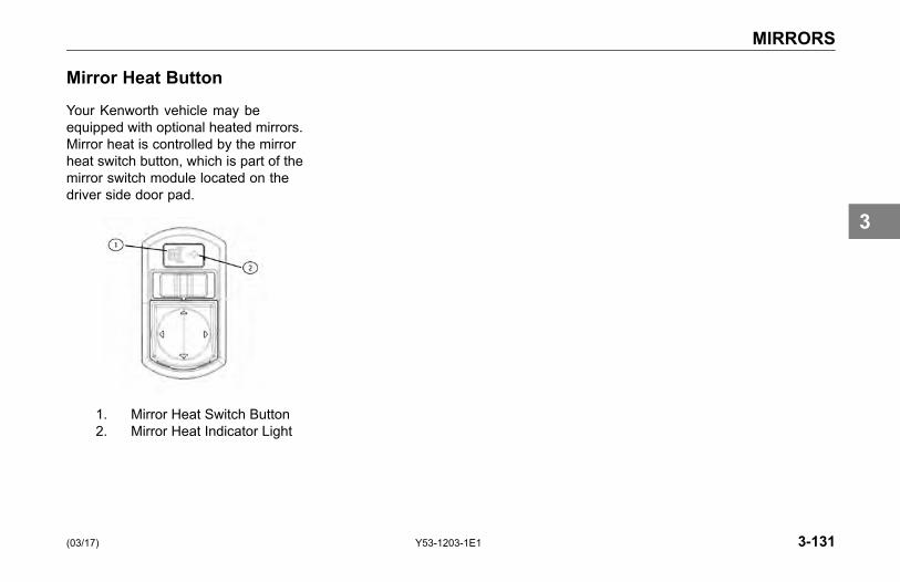
MIRRORS
Mirror Heat Button
Your Kenworth vehicle may beequipped with optional heated mirrors.Mirror heat is controlled by the mirrorheat switch button, which is part of themirror switch module located on thedriver side door pad.
1. Mirror Heat Switch Button2. Mirror Heat Indicator Light
(03/17) Y53-1203-1E1 3-131
3

DRIVING
DRIVING TIPS AND TECHNIQUESIntroduction . . . . . . . . . . . . . . . . . . 4-5Coasting . . . . . . . . . . . . . . . . . . . . 4-5Descending a Grade . . . . . . . . . . . . . . 4-6Economical Driving . . . . . . . . . . . . . . . 4-6Fuel - Excess Consumption . . . . . . . . . . . 4-8Safe Driving . . . . . . . . . . . . . . . . . . 4-9Cruise Control . . . . . . . . . . . . . . . . 4-11Air Suspension Height/Air Pressure . . . . . . . 4-12Fifth Wheel. . . . . . . . . . . . . . . . . . 4-14
OPERATING THE BRAKE SYSTEMIntroduction . . . . . . . . . . . . . . . . . 4-16Air Supply System . . . . . . . . . . . . . . 4-17Using the Parking Brake . . . . . . . . . . . . 4-19European Air System Parking Brake Option forExport Vehicles . . . . . . . . . . . . . . . 4-22
Vehicle/Trailer Air Supply Valve . . . . . . . . . 4-23
(03/17) Y53-1203-1E1 4-1
4
DRIVING
Brake Safety and Emergency. . . . . . . . . . 4-27Automatic Traction Control . . . . . . . . . . . 4-29Anti-Lock Brake Systems (ABS) . . . . . . . . 4-29Advanced ABS with Stability Control. . . . . . . 4-32Trailer Brake Hand Valve. . . . . . . . . . . . 4-39Driving with an Unloaded Trailer . . . . . . . . 4-40Engine Retarders . . . . . . . . . . . . . . . 4-40Exhaust Brake . . . . . . . . . . . . . . . . 4-41Engine Brakes . . . . . . . . . . . . . . . . 4-42Brake Components . . . . . . . . . . . . . . 4-43
OPERATING THE ENGINEIntroduction . . . . . . . . . . . . . . . . . 4-45Starting Procedure - Normal Temperature . . . . 4-46Starting Procedure - Cold Weather . . . . . . . 4-47Engine Block and Oil Pan Heater (Option) . . . . 4-47Engine Warm-up . . . . . . . . . . . . . . . 4-48Ether Metering Equipment . . . . . . . . . . . 4-51Cruise Control . . . . . . . . . . . . . . . . 4-52
4-2 Y53-1203-1E1 (03/17)
4

DRIVING
Engine Fan Control . . . . . . . . . . . . . . 4-54Engine Control Display . . . . . . . . . . . . 4-55Engine Shutdown System . . . . . . . . . . . 4-55
OPERATING THE REAR/DRIVE AXLEIntroduction . . . . . . . . . . . . . . . . . 4-57Inter-Axle Differential Lock . . . . . . . . . . . 4-57Driver Controlled Main Differential Lock . . . . . 4-60Dual Range (Two-Speed) Rear Axle . . . . . . . 4-61Auxiliary Axles - Pusher or Tag . . . . . . . . . 4-63
OPERATING THE TRANSMISSIONIntroduction . . . . . . . . . . . . . . . . . 4-70Transmission Warm-Up . . . . . . . . . . . . 4-70Operating Manual Transmissions . . . . . . . . 4-71Putting the Vehicle in Motion . . . . . . . . . . 4-71More Transmission Tips . . . . . . . . . . . . 4-74Operating Automatic Transmissions . . . . . . . 4-76Auxiliary Transmissions . . . . . . . . . . . . 4-77Steerable Drive Axle . . . . . . . . . . . . . 4-77
(03/17) Y53-1203-1E1 4-3
4
DRIVING
SHUT-DOWNIntroduction . . . . . . . . . . . . . . . . . 4-78Final Stopping Procedures . . . . . . . . . . . 4-78Before Stopping the Engine . . . . . . . . . . 4-79Refueling . . . . . . . . . . . . . . . . . . 4-80Sleeper Bunk. . . . . . . . . . . . . . . . . 4-81
4-4 Y53-1203-1E1 (03/17)
4

DRIVING TIPS AND TECHNIQUES
DRIVING TIPS ANDTECHNIQUES
Introduction
This section covers driving tips andtechniques on how to drive yourKenworth efficiently. For furtherinformation on driving techniques, readthe Truck Driver Handbook includedin your glove box literature package.It will give you more tips on starting,shifting, and driving your vehicle.
Coasting
Do not coast with the transmissionin neutral or with the clutch pedaldepressed.
WARNING!Do not coast with the transmissionin neutral or with the clutch pedaldepressed, it is a dangerous prac-tice. Without the use of the retardingpower of the drivetrain, your vehiclecan reach dangerous speeds. Atvery high speeds you may not beable to put the transmission in anygear. At high speeds you could seri-ously damage your vehicle or causean accident when you put the trans-mission in gear. The engine speedcould exceed the maximum gov-erned speed and cause a seriousaccident due to mechanical failures.Failure to comply may result in per-sonal injury, death, equipment orproperty damage.
Besides being illegal and dangerous,coasting is also expensive. It causespremature failure or damage to theclutch and transmission and overloadsthe brake system.
Coasting with the transmissionin neutral also prevents propertransmission component lubrication.During coasting the transmission isdriven by the rear wheels, and thecountershaft gear (which lubricatesthe transmission components by oilsplash) will only be turning at idlespeed.
(03/17) Y53-1203-1E1 4-5
4
DRIVING TIPS AND TECHNIQUES
Descending a Grade
WARNING!Do not hold the brake pedal downtoo long or too often while goingdown a steep or long grade. Thiscould cause the brakes to overheatand reduce their effectiveness. Asa result, the vehicle will not slowdown at the usual rate. To reducethe risk of personal injury and/or anaccident, before going down a steepor long grade, reduce speed andshift the transmission into a lowergear to help control your vehiclespeed. Failure to follow proceduresfor proper downhill operation couldresult in loss of vehicle control andmay result in personal injury, death,equipment or property damage.
Economical Driving
The following section includesrecommendations for best engineperformance and economy:
Engine Overspeed - RPM
• Operate the engine within theoptimum engine RPM range anddo not allow the RPM's to exceedthe maximum governed speed.See your Engine Operationand Maintenance manual forinformation regarding engineRPM.
• When the engine is used as abrake to control vehicle speed(e.g., while driving down a grade),do not allow the engine RPMto exceed maximum governedspeed.
• Under normal load and roadconditions operate the engine inthe lower end of the range.
4-6 Y53-1203-1E1 (03/17)
4

DRIVING TIPS AND TECHNIQUES
NOTEOften these recommendations aresecondary to maintaining an ade-quate and safe speed relative to thesurrounding traffic and road condi-tions.
CAUTIONTo avoid engine damage, do not letthe engine RPM go beyond the max-imum governed RPM valve damagecould result if overspeed conditionsoccur.
Use of Tachometer
The tachometer is an instrument thataids in obtaining the best performanceof the engine and manual transmission,serving as a guide for shifting gears.Refer to the Engine Operation andMaintenance manual for optimumengine RPM.
• If the engine RPM moves beyondthe maximum governed speed,indicating an overspeed condition,apply the service brake or shift toa higher gear to bring engine RPMwithin the optimum speed range.
• When driving downhill: shift to alower gear, use the engine brake(if so equipped), and use theservice brake, keeping the enginespeed below 2,100 rpm.
When the engine speed reachesits maximum governed speed, theinjection pump governor cuts off fuelto the engine. However, the governor
has no control over the engine RPMwhen it is being driven by the vehicle'stransmission, for example, on steepdowngrades. Apply service brakes orshift to a higher gear.
(03/17) Y53-1203-1E1 4-7
4

DRIVING TIPS AND TECHNIQUES
Fuel economy and engineperformance are also directlyrelated to driving habits:
• The best results in trip time andfuel economy are obtained whiledriving the vehicle at a steadyspeed.
• Shift into higher or lower gears (orapply the service brake) to keepengine RPM near the lower end ofthe optimum operating range.
• Avoid rapid acceleration andbraking.
Fuel - Excess Consumption
The vehicle's fuel consumption isconnected to three important factors:maintenance, driving habits, andgeneral condition of the road, trafficconditions, and vehicle load.
Maintenance
Proper maintenance will keep thevehicle running like new even afterlong periods of use. The driver mustperform the daily and weekly checksof the vehicle.
Maintenance factors affecting fuelconsumption:
• air and/or fuel filters clogged
• engine valves out of adjustment
• injection pump improperlysynchronized
• injection nozzles defective oruncalibrated
• improperly inflated tires
• wheel bearings improperlyadjusted
• clutch improperly adjusted or worn(slipping)
• fuel leaks
4-8 Y53-1203-1E1 (03/17)
4

DRIVING TIPS AND TECHNIQUES
Driving Habits
Wrong driving habits must becorrected and the recommendationson economic driving should befollowed.
Driving factors affecting fuelconsumption:
• excessive speed and unnecessaryfast acceleration
• long periods of idling
• driving with foot resting on the(manual transmission) clutchpedal
General Condition
Other factors affecting fuelconsumption are related to loadsand type of roads on which the vehicleoperates. It is not always possible tochoose the most adequate road, butit must be kept in mind that the idealroad is the one that allows a steadyspeed in high gear, without requiringfrequent braking and acceleration.
The following general conditionscan affect fuel consumption:
• overload
• unbalanced load
• very high load
• inadequate roads
• traffic conditions
Safe Driving
NOTEThe following recommendations aremerely informative and do not coverall safety precautions. Safe drivingis, above all, the responsibility of thedriver.
The safe operation of a vehicle isnot just following the establishedtraffic rules, but should also include:maintaining the vehicle in goodmechanical condition, and properoperation of the engine, transmission,and brakes.
(03/17) Y53-1203-1E1 4-9
4
DRIVING TIPS AND TECHNIQUES
The following guidelines will helpyou to drive the vehicle safely:
• Make a thorough inspection of thevehicle, daily and weekly. SeeDriver's Check List on page 1-35.
• Ensure that windows, mirrors, andlights are clean.
• Check all tires for damage andcorrect inflation pressure.
• Adjust the seat to a comfortabledriving position, for easy access topedals and vehicle controls.
• Adjust rear view mirrors.
• Always use the safety belts.
• Do not exceed the GVWR.
• Proportionally distribute loads onthe frame.
• Always keep the brakes adjustedand in proper condition. See
Checks and Adjustments on page5-51.
• Obey speed limits and all trafficsignals.
• When driving downhill, select onegear lower than the up-hill gear.And use the brakes properly, donot ride them.
• Do not exceed maximum governedspeed (as specified in the EngineOperation and MaintenanceManual).
WARNING!Do not exceed the specified load rat-ing. Overloading can result in lossof vehicle control and personal in-jury, either by causing componentfailures or by affecting vehicle han-dling. Exceeding load ratings canalso shorten the service life of thevehicle. Failure to comply may re-sult in personal injury, death, equip-ment or property damage.
• The components of yourvehicle are designed to providesatisfactory service if the vehicleis not loaded in excess of eitherthe gross vehicle weight rating(GVWR), or the maximum frontand rear gross axle weight ratings(GAWRs). (Axle weight ratings arelisted on the driver's door edge.)
4-10 Y53-1203-1E1 (03/17)
4
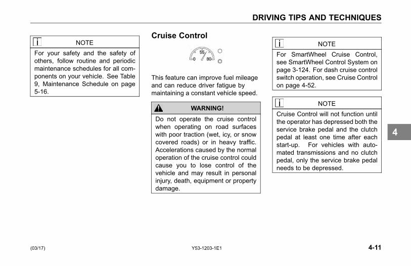
DRIVING TIPS AND TECHNIQUES
NOTEFor your safety and the safety ofothers, follow routine and periodicmaintenance schedules for all com-ponents on your vehicle. See Table9, Maintenance Schedule on page5-16.
Cruise Control
This feature can improve fuel mileageand can reduce driver fatigue bymaintaining a constant vehicle speed.
WARNING!Do not operate the cruise controlwhen operating on road surfaceswith poor traction (wet, icy, or snowcovered roads) or in heavy traffic.Accelerations caused by the normaloperation of the cruise control couldcause you to lose control of thevehicle and may result in personalinjury, death, equipment or propertydamage.
NOTEFor SmartWheel Cruise Control,see SmartWheel Control System onpage 3-124. For dash cruise controlswitch operation, see Cruise Controlon page 4-52.
NOTECruise Control will not function untilthe operator has depressed both theservice brake pedal and the clutchpedal at least one time after eachstart-up. For vehicles with auto-mated transmissions and no clutchpedal, only the service brake pedalneeds to be depressed.
(03/17) Y53-1203-1E1 4-11
4
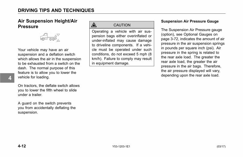
DRIVING TIPS AND TECHNIQUES
Air Suspension Height/AirPressure
Your vehicle may have an airsuspension and a deflation switchwhich allows the air in the suspensionto be exhausted from a switch on thedash. The normal purpose of thisfeature is to allow you to lower thevehicle for loading.
On tractors, the deflate switch allowsyou to lower the fifth wheel to slideunder a trailer.
A guard on the switch preventsyou from accidentally deflating thesuspension.
CAUTIONOperating a vehicle with air sus-pension bags either overinflated orunder-inflated may cause damageto driveline components. If a vehi-cle must be operated under suchconditions, do not exceed 5 mph (8km/h). Failure to comply may resultin equipment damage.
Suspension Air Pressure Gauge
The Suspension Air Pressure gauge(option), see Optional Gauges onpage 3-72, indicates the amount of airpressure in the air suspension springsin pounds per square inch (psi). Airpressure in the spring is related tothe rear axle load. The greater therear axle load, the greater the airpressure in the air bags. Therefore,the air pressure displayed will vary,depending upon the rear axle load.
4-12 Y53-1203-1E1 (03/17)
4

DRIVING TIPS AND TECHNIQUES
Driving with Deflated Air Springs
If an air spring ruptures, there willbe enough air pressure to drive thevehicle to a safe stop off the highwayto investigate the problem.
To get to a repair facility, do thefollowing:
1. Remove the height control linkconnected to the axle and tothe suspension air valve controlarm. This will cause the air valvecontrol arm to center in the closedposition.
2. The air system can then bepumped up to normal pressure forcontinued operation.
WARNING!Low air pressure could make brakesunsafe for driving by not providingsufficient air brake application pres-sure in an emergency, which couldlead to an accident. Before drivingthe vehicle, make sure the air pres-sure pumps up to over 100 psi (689kPa) for normal brake operation. Ifit does not reach 100 psi (689 kPa),do not try to move the vehicle. Fail-ure to comply may result in personalinjury, death, equipment or propertydamage.
(03/17) Y53-1203-1E1 4-13
4
DRIVING TIPS AND TECHNIQUES
Fifth Wheel
The following applies to tractorconfigurations:
WARNING!Ensure that all fifth wheel mainte-nance, adjustments, and rebuildingare done only by a qualified me-chanic. An improperly maintainedfifth wheel can cause a trailer to sep-arate from a tractor. This could leadto a serious accident. Failure tocomply may result in personal injury,death, equipment or property dam-age.
Your Kenworth is equipped with eithera Fixed or an Air-Controlled SlidingFifth Wheel. Either type should selflock when a trailer king pin trips thelocking dogs as the tractor is backedunder a trailer.
Fifth Wheel Jaw LockTo unlock the fifth wheel lock:
• Pull out on the lever (usuallylocated on the left-hand side of thefifth wheel) until it remains in anover center position.
Hook Up:
• After connecting your tractor to thetrailer, always inspect the jaws tobe sure they have locked on thekingpin before driving.
Air-Controlled Sliding Fifth Wheel
Vehicles having an air-controlledsliding fifth wheel have a fifth wheelslider lock controlled by a switch on theaccessory switch panel. To operatethis type of lock, move the switch tothe appropriate position. By placingthe switch in the UNLOCK position,you can slide the fifth wheel to variouspositions to adjust weight distribution.There is a guard on this switch toprotect you against accidentallyactivating or releasing the lock.
4-14 Y53-1203-1E1 (03/17)
4

DRIVING TIPS AND TECHNIQUES
WARNING!Do not move the fifth wheel while thetractor-trailer is in motion. Your loadcould shift suddenly, causing you tolose control of the vehicle, which canresult in an accident. Never operatethe vehicle with the switch in the UN-LOCK position. Always inspect thefifth wheel after you lock the switchto be sure the fifth wheel lock is en-gaged. Failure to comply may resultin personal injury, death, equipmentor property damage.
Fifth Wheel Lubrication
• Frequently operate and lubricatemovable or sliding fifth wheels toprevent corrosion.
CAUTIONBoth the fifth wheel plate and theslide tracks (if a slider) should becleaned and lubricated periodicallyto ensure smooth turning and slid-ing action. Failure to keep these sur-faces lubricated can lead to frame ordriveline damage.
See Frame and Fifth Wheel on page5-99, for maintenance information.
(03/17) Y53-1203-1E1 4-15
4

OPERATING THE BRAKE SYSTEM
OPERATING THEBRAKE SYSTEM
Introduction
The operation of the vehicle's brakingsystem and many vehicle accessoriesdepends upon the storage andapplication of a high-pressure airsupply.
This air brake system is of the dualcircuit type: it has a circuit for the frontwheels, a separate circuit for the rearwheels, and one for the trailer. Thesystem is supplied by an engine-drivencompressor. The vehicle's compressortakes outside air and compresses it,usually to 100-130 psi (689-896 kPa).The compressor air then goes to theair tanks to be stored until needed.
When you operate your air brakes, thestored compressed air flows into thechambers where it is used to applyyour truck and trailer brakes. That
is why, when you push down on thebrake pedal, you do not feel the sameamount of pressure on the pedal thatyou do when you apply the brakes onyour car. All you are doing on yourtruck is opening an air valve to allowair to flow into the brake chambers.
WARNING!The brake system is a critical vehiclesafety system. For the safety of youand others around you, have the ve-hicle submitted for periodic preven-tive maintenance checks as well ashaving any suspected problems im-mediately checked by an authorizedKenworth Dealer. Failure to prop-erly maintain your brake system canlead to serious accidents. Failure tocomply may result in personal injury,death, equipment or property dam-age.
WARNING!Never drive your vehicle with theparking brake applied. Always re-lease the parking brakes prior tomoving the vehicle. Failure to dis-engage the parking brakes prior tomoving your vehicle could result inexcessive heat buildup in the brakesystem, resulting in a fire. Failureto comply may result in personalinjury, death, equipment or propertydamage.
NOTEToday's diesel electronic engineshave significant torque and starta-bility power at low RPM. Combina-tions of engine speed and availabletorque may over-power the vehiclesparking brakes.
4-16 Y53-1203-1E1 (03/17)
4
OPERATING THE BRAKE SYSTEM
Air Supply System
Contamination of the air supply systemis the major cause of problems inair-operated components such asbrake valves and suspension heightcontrol valves. To keep contaminantsto the lowest possible level, follow allmaintenance procedures.
Air Dryer
Bendix AD-IS Series Air Dryers
WARNING!If a different air dryer brand or modelis installed on the vehicle other thanwhat was originally installed, it couldcause the air system to not performcorrectly unless the full air systemdesign is reviewed and modifica-tions made to comply with FederalMotor Vehicle Safety Standards(FMVSS 121 - Air Brake Systems)or, in the case of chassis equippedwith the European air system, ECER13. Failure to abide by this warningand maintain compliance to FMVSS121 or ECE R13 could cause lossof vehicle control and may lead topersonal injury or death.
Your Kenworth vehicle may beequipped with a Bendix AD-IS seriesair dryer. Any air dryer replacementshould be made with an identicalcomponent.
The AD-IS Series air dryer hasincorporated into its design variouscomponents that have typically beeninstalled separately on the vehicle (seebelow for components/ areas affected).
• Pressure protection valves
• Safety valve
• Governor and plumbing
• Plumbing of the front and rearservice air tanks
• Plumbing to accessory systems
(03/17) Y53-1203-1E1 4-17
4
OPERATING THE BRAKE SYSTEM
These components are requiredto meet the Federal Motor VehicleSafety Standards (FMVSS 121 - AirBrake Systems) or, in the case ofchassis equipped with the Europeanair system, ECE R13. As the Warningabove states, any other type of airdryer installed in the place of anAD-IS Series will require changes,modifications, and/or additions toyour vehicle’s air system to maintaincompliance with FMVSS 121 or ECER13. Kenworth strongly recommendsthat if the air dryer is changed from anAD-IS series, you consult your nearestauthorized Kenworth dealer.
Brake Operation
WARNING!Do not drive through water deepenough to wet brake components,as it may cause the brakes to workless efficiently than normal. Thevehicle's stopping distance may belonger than expected, and the vehi-cle may pull to the left or right whenbrakes are applied, which couldcontribute to an accident. Failureto comply may result in personalinjury, death, equipment or propertydamage.
To rectify this condition, check the rearand both sides of the vehicle for cleartraffic, then apply the brakes gently,releasing and gently reapplying untilthe brakes dry out, restoring normaloperation. Always check brakes afterdriving through deep water to helpreduce the possibility of personal injuryor an accident.
Front Brake System
When the brake pedal is depressed,the front circuit portion of the treadlevalve delivers air from the frontservice air tank to the front axle brakechambers via a quick-release valve.
Simultaneously (on full truckconfigurations), air is also suppliedto the modulating valve control port.In the event of a rear service circuitfailure, the modulating valve willexhaust air from the spring brakechambers, applying the spring brakesin proportion to the front circuitapplication.
4-18 Y53-1203-1E1 (03/17)
4

OPERATING THE BRAKE SYSTEM
Rear Brake System
When the brake pedal is depressed,the rear circuit portion of the treadlevalve delivers air from the rear serviceair tank to the service brake relayvalve control port. The relay valvethen delivers air directly from therear service air tank to the rear brakechambers in proportion to the treadlepressure.
On tractors without ABS, the relayvalve is part of the BP-R1 brakevalve, which automatically proportionsthe drive axle brake applicationpressure when driving bobtail (withouta trailer connected). The proportioningBP-R1 brake valve allows full useof the steer axle (front) brakes andreduces the chance that the drive axlebrakes will lockup. The bobtail brakeproportioning system is automaticallyturned off when a trailer is connected.
Using the Parking Brake
The yellow diamond-shaped knob onthe dash controls the vehicle parkingbrakes. These are spring brakes thatyou activate by releasing air pressurefrom their chambers. When they arenot in use, air pressure compressesthe springs and releases the brakes.Pulling the valve OUT applies theparking brake, which exhausts air fromthe chambers and allows the springsto extend and apply the brakes.
WARNING!Do not leave the cab without apply-ing the parking brake. The vehiclecould roll and cause an accident. Al-ways apply the parking brake beforeyou leave the cab. Failure to complymay result in personal injury, death,equipment or property damage.
Combination ( Vehicle/Trailer) ParkingBrake Control Valves
1 Parking Brake Control(Yellow)
2 Trailer Air Supply Control(Red)
(03/17) Y53-1203-1E1 4-19
4

OPERATING THE BRAKE SYSTEM
Before you leave the cab:
1. Apply all parking brakes. Pullout the Yellow Parking BrakeControl knob (1) located on thedash. The Red (octagon-shaped)Trailer Air Supply Control knob willautomatically pop out. (A dashwarning light will indicate when thebrake is ON.)
2. Shift the transmission into PARKposition:
° manual transmission, selectFirst or Reverse gear.
° automatic transmission, selectNeutral.
3. Turn the key to OFF.
4. Remove the key.
WARNING!Do not pull out the parking brakevalve while the vehicle is moving.Stopping with the parking brake con-trols can cause a suddenwheel lock-up, loss of control, or over-take byfollowing vehicles. Failure to complymay result in personal injury, death,equipment or property damage.
The parking brakes act on the rearwheels only. They are spring-applied,with air pressure used to release them.Release air is supplied by both thefront and rear circuit air tanks througha double check valve.
To release the vehicle parkingbrakes ONLY:
• Push IN the Yellow knob on thedash. Your trailer will remainparked.
• Below 60 psi (414 kPa) the Yellowparking brake valve remains OUT(ON position). If air pressure is notrestored above 60 psi (414 kPa),the knob will automatically returnto the OUT position if you attemptto push it in. See Primary andSecondary Air Pressure on page3-70.
4-20 Y53-1203-1E1 (03/17)
4

OPERATING THE BRAKE SYSTEM
To release the trailer brakes ONLY:
• Push IN the Red knob on the dash.The vehicle will remain parked.
To release the full combination ofbrakes:
• Push IN BOTH knobs on the dash.
• In the event that air pressure isreduced below a safe level: thelow air warning light will come onfirst; if air pressure continues todrop, the parking brake valve willpop OUT, automatically applyingthe spring brakes.
CAUTIONDo not try to put the vehicle in mo-tion before pressure in the systemreaches 100 psi (689 kPa) becausethe wheels are locked by the springbrake action. Unnecessary stressand possible brake malfunctioncould occur if the vehicle is forced tomove before the air system reaches100 psi (689 kPa). Failure to complymay result in equipment damage.
WARNING!If the air pressure falls below 60psi (414 kPa) the spring brakesmay stop the vehicle abruptly, whichcould result in an accident. Ob-serve the red warning lamps on thegauges. If one comes on, do notcontinue to drive the vehicle until ithas been properly repaired or ser-viced. Failure to comply may resultin personal injury, death, equipmentor property damage.
(03/17) Y53-1203-1E1 4-21
4

OPERATING THE BRAKE SYSTEM
WARNING!Do not use the trailer hand brake orservice brakes to park and hold anunattended vehicle, use the parkingbrakes. Because service brakeswork with air pressure, these brakescould slowly release. Your vehiclecould roll, causing a serious ac-cident. Never rely on the servicebrakes to hold a parked vehicle.Failure to comply may result in per-sonal injury, death, equipment orproperty damage.
European Air SystemParking Brake Option forExport Vehicles
Parking Brake Operation
WARNING!Never drive your vehicle with theparking brake applied. Always re-lease the parking brake prior to mov-ing the vehicle. Failure to disen-gage the parking brake prior to mov-ing your vehicle could result in ex-cessive heat build-up in the brakesystem, resulting in a fire. Failure tocomply may result in personal injury,death, equipment or property dam-age.
NOTEToday’s electronic diesel engineshave significant torque and starta-bility power at low RPM. Combina-tions of engine speed and availabletorque may over-power the vehicle’sparking brake.
WARNING!Do not leave the cab without apply-ing the parking brake. The truckcould roll and cause an injury ac-cident. Always apply the parkingbrake before you leave the cab. Fail-ure to comply may result in personalinjury, death, equipment or propertydamage.
4-22 Y53-1203-1E1 (03/17)
4
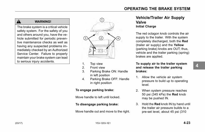
OPERATING THE BRAKE SYSTEM
WARNING!The brake system is a critical vehiclesafety system. For the safety of youand others around you, have the ve-hicle submitted for periodic preven-tive maintenance checks as well ashaving any suspected problems im-mediately checked by an AuthorizedService Center. Failure to properlymaintain your brake system can leadto serious injury accidents.
1. Top view2. Front view3. Parking Brake ON: Handle
in left position4. Parking Brake OFF: Handle
in right position
To engage parking brake:
Move handle to left until locked.
To disengage parking brake:
Move handle out and move to the right.
Vehicle/Trailer Air SupplyValveInitial Charge
The red octagon knob controls the airsupply to the trailer. With the systemcompletely discharged, both the Red(trailer air supply) and the Yellow(parking brake) knobs are OUT; thus,vehicle and the trailer parking (spring)brakes are applied.
To supply air to the trailer systemand release the trailer parkingbrakes:
1. Allow the vehicle air systempressure to build up to operatinglevel.
2. When system pressure reaches50 psi (345 kPa) the Red knobmay be pushed IN.
3. Hold the Red knob IN by hand untilthe trailer air pressure builds to apre-set level, about 45 psi (310
(03/17) Y53-1203-1E1 4-23
4
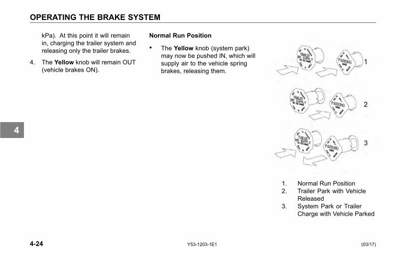
OPERATING THE BRAKE SYSTEM
kPa). At this point it will remainin, charging the trailer system andreleasing only the trailer brakes.
4. The Yellow knob will remain OUT(vehicle brakes ON).
Normal Run Position
• The Yellow knob (system park)may now be pushed IN, which willsupply air to the vehicle springbrakes, releasing them.
1. Normal Run Position2. Trailer Park with Vehicle
Released3. System Park or Trailer
Charge with Vehicle Parked
4-24 Y53-1203-1E1 (03/17)
4

OPERATING THE BRAKE SYSTEM
Trailer Park or Emergency BrakeApplication Only
If you ever have a failure or disconnectthe air supply hose to the trailer, thetrailer parking brakes will set. The Redknob will automatically pop OUT andseal off the vehicle air tanks to protectthe vehicle air system pressure.
To apply the trailer brakes only:
Pull OUT the Red knob. This willexhaust air from the trailer supply line,causing the vehicle protection valve toclose and the trailer spring brakes toapply. The trailer is now in emergencyor park. This mode would be usedto uncouple from the trailer (runningwithout a trailer connected).
WARNING!Do not use the trailer hand brake orservice brakes to park and hold anunattended vehicle, use the parkingbrakes. Because service brakeswork with air pressure, these brakescould slowly release. Your vehiclecould roll, causing a serious ac-cident. Never rely on the servicebrakes to hold a parked vehicle.Failure to comply may result in per-sonal injury, death, equipment orproperty damage.
System Park
With both knobs pushed in for normaloperating modes, the parking brakesof both the vehicle and the trailermay be applied by pulling the Yellowknob OUT. This will exhaust the airfrom the vehicle spring brakes, andsimultaneously cause the Red knob topop OUT, which will apply the trailerbrakes. This complies with the FederalMotor Vehicle Safety Standards(FMVSS) 121 requirement that onecontrol should apply all the parkingbrakes on the vehicle.
(03/17) Y53-1203-1E1 4-25
4
OPERATING THE BRAKE SYSTEM
Trailer Charge
If both knobs are OUT (combinationvehicle is parked), and it is desired torecharge the trailer, the Red knob maybe pushed IN repressurizing the trailersupply line. The vehicle will remainparked. For more information on airsupply pressure requirements, seeInitial Charge on page 4-23.
Trailer Unload Air Assist System
If your vehicle is equipped with a trailerunload air assist system, Kenworthhas provided the air supply and thevehicle’s portion of the controls for thesystem. Please read and understandthe operating instructions below andprovided by the trailer manufacturerbefore operating the system.
CAUTIONThis vehicle is equipped with a trailerair assist system. Do not exceed thetrailer manufacturers recommendedair pressure or apply air pressure be-fore the trailer unload mechanism isin the open position. Failure to com-ply could result in inability to unloadyour trailer or cause damage to theunload system. Contact the trailerair assist manufacturer for further in-formation, operating settings and in-structions.
Due to the variation in tank trailers,please consult the trailer manufacturerfor air assist unloading information.Follow the basic operating instructionslisted below:
General Operating Instructions:
1. Apply parking brakes.
2. Open trailer unload air assistsystem.
3. Apply trailer unload air assistpressure.
NOTEKenworth has installed a parkingbrake interlock device on the ve-hicle. The parking brake must beengaged for the system to operate.
The vehicle’s portion of the trailerunload air assist system is equippedwith a pressure limiting valve set at 20psi (138 kPa). Please review the trailer
4-26 Y53-1203-1E1 (03/17)
4

OPERATING THE BRAKE SYSTEM
manufacturer’s instructions for theoperating pressure required to operatethe trailer unload system.
Brake Safety and Emergency
WARNING!Do not operate the vehicle in theevent of a malfunction in any air cir-cuit. The vehicle should not be op-erated until the system is repairedand both braking circuits, includingall pneumatic and mechanical com-ponents, are working properly. Lossof system air can cause the servicebrakes to not function resulting inthe sudden application of the springbrakes causing wheel lock-up, lossof control, or overtake by followingvehicles. Failure to comply may re-sult in personal injury, death, equip-ment or property damage.
• If pressure is lost in the vehiclefront or rear circuit, the "check"valves isolate the unaffectedcircuit, allowing this circuit tocontinue normal operation. Thetrailer brakes are still functional.
• If air pressure is lost in thetrailer supply/park circuit, and thepressure drops below 60 psi (414kPa), the trailer spring brakes areautomatically applied, and thevehicle air pressure circuits areunaffected.
• If air pressure is lost in the trailerbrake service circuit, and thepressure in the vehicle front andrear circuits drops below 60 psi(414 kPa), the vehicle and trailerspring brakes are automaticallyapplied.
(03/17) Y53-1203-1E1 4-27
4

OPERATING THE BRAKE SYSTEM
Emergency Braking
WARNING!Unless you have an anti-lock brak-ing system (ABS), always avoidcompletely depressing the servicebrake pedal, if possible, even dur-ing emergency braking. Depressingthe brake pedal too aggressivelycan cause the wheels to lock, whichcan lead to an uncontrolled skid andcan result in an accident. Failureto comply may result in personalinjury, death, equipment or propertydamage.
For Non-ABS Vehicles: to stop yourvehicle in an emergency, vary theservice brake application pressureto provide maximum braking forcewithout locking the wheels. Use enginecompression to assist the servicebrakes by not depressing the clutchpedal until the engine reaches idlespeed.
Overheated Brakes
Under normal braking conditions, theenergy generated will bring the internalbrake drum temperature to about 500˚F (260˚ C). This is well within the safezone: the maximum safe temperatureof lining for drum type brakes is usuallyabout 800˚ F (427˚ C).
If service brakes are used foremergency braking, used improperly,or for prolonged periods, internal brakedrum temperatures may exceed 800˚F (427˚ C). Such brake overheatingmay be detected by a burning smellor smoke coming from a drum. If thisoccurs, you should immediately stopand check for cracked brake drums orlining fires. If neither exists, continuedriving and resume a slow speed assoon as possible to cool the brakes. Ifthe vehicle was to remain stopped, theheat transfer could destroy the liningsand distort the brake drum.
To prevent drums from distortionwhile they cool down:
• Park the vehicle on level surfaceand block the wheels.
• Release the parking brake andallow the brakes to cool down.See Parking Brake Valve on page3-107.
4-28 Y53-1203-1E1 (03/17)
4
OPERATING THE BRAKE SYSTEM
Automatic Traction Control
General information on ABS andautomatic traction control.
Your truck/tractor ABS is equipped withan automatic traction control (ATC)feature. This feature is controlled bya switch on the dash. Do not allowthe traction control lamp to remain oncontinuously for an extended lengthof time. Extended continuous use ofthe ATC can cause overheating of thedrive wheel brakes. Engine torqueor vehicle speed should be reducedto eliminate wheel spin and preventexcessive application of the ATCsystem. Except for checking for properillumination of the ABS and tractioncontrol warning lamps when firststarting the vehicle, and for monitoring
these lamps while driving, no specialoperating procedures are required.For detailed system description, seeliterature for your specific ABS thatwas provided with your vehicle.
Anti-Lock Brake Systems(ABS)
Information on using the anti-lockbrake system.
This vehicle is equipped with ananti-lock braking system (ABS).ABS reduces the possibility of wheellock-up. If a wheel is about tolock during braking, the ABS willautomatically adjust air pressure to thebrake chambers on the appropriatewheel(s) to prevent wheel lock-up. TheABS is automatically turned on whenthe ignition switch is turned on.
(03/17) Y53-1203-1E1 4-29
4
OPERATING THE BRAKE SYSTEM
WARNING!The Anti-Lock Brake System isa critical vehicle safety system.For the safety of you and othersaround you, have the vehicle sub-mitted for periodic preventive main-tenance checks as well as havingany suspected problems immedi-ately checked by an authorizeddealer. Failure to properly maintainyour brake system can lead to se-rious accidents. Failure to complymay result in death, personal injury,equipment or property damage.
WARNING!Do not rely on an anti-lock brake sys-tem that is functioning improperly.You could lose control of the vehi-cle resulting in a severe accident,causing death or personal injury. Ifyour ABS lamp goes on while youare driving or stays on after the self-check, your anti-lock system mightnot be working. The ABS may notfunction in an emergency. You willstill have conventional brakes, butnot anti-lock brakes. If the lamp in-dicates a problem, have the ABSchecked.
Vehicles without ABS are typicallyequipped with a bobtail brakeproportioning system. When a traileris not connected, the drive axle brakeapplication pressure will automaticallybe limited by the proportioning system.When driven in a bobtail mode,these tractors will require greater
brake pedal application to provide theequivalent braking to a bobtail tractornot equipped with a proportioningsystem.
4-30 Y53-1203-1E1 (03/17)
4
OPERATING THE BRAKE SYSTEM
Trailer ABS Power LineCommunication (PLC)
North American on-highway vehiclesare equipped with a separate electricalcircuit to power the ABS on towedvehicle(s). In most cases, the ABSpower will be supplied through theAuxiliary circuit on the primary 7-waytrailer light line connector. If the vehiclewas manufactured with a switchableAuxiliary circuit for trailer accessories,an additional 7-way connector wouldhave been provided for trailer ABSpower. In either case, the ABSpower line on the vehicle will be PLCequipped.
CAUTIONDo not splice into the non-switchableAuxiliary circuit on the primary 7-waytrailer light line. Doing so may causethe trailer ABS to malfunction. Thiscircuit is dedicated for trailer ABSpower. To add a switchable auxiliarycircuit, contact a dealership.
NOTETractors/Trucks and trailers built af-ter 03/01/2001 must be able to turnon an In-Cab Trailer ABS WarningLamp (per U.S. FMVSS121). Theindustry chose Power Line Com-munication (PLC) as the standardmethod to turn it on. On trailers builtprior to 03/01/2001, verify trailerABS status via the required externalwarning lamp mounted on the trailer.The indicator lamp on the trailershould be yellow and identified withthe letters ABS.
For doubles or triples, the lamp doesnot distinguish between trailers. AnABS problem in any of the trailerswill activate the Trailer ABS WarningLamp.
If you change the intended servicein any way (e.g., number of axles,multiple trailers, add switchabletrailer accessories, etc.) from the
date the vehicle was manufactured,you should contact your trailermanufacturer and/or trailer anti-lockbrake manufacturer to determine if thepower available at the 7-way trailerlight line is adequate. Failure to doso might result in insufficient power tothe trailer ABS, which may affect itsoperation.
CAUTIONThe center pin of the 7-way trailerlight line may be constantly poweredfor ABS. Make sure it will not acci-dently turn on trailer equipment.
(03/17) Y53-1203-1E1 4-31
4

OPERATING THE BRAKE SYSTEM
Special Trailer ABS (Without PLC)Option
If a trailer does not have PLC, butit does have ABS that is poweredthrough an optional second trailerconnector (ISO 3731) and that trailerABS is designed to control the TrailerABS Warning Lamp in the cab andthe vehicle has been ordered with theoption to turn on this lamp for thesetypes of trailers, then this lamp willturn on when that trailer ABS has aproblem. This should be checked by adealer as soon as possible. The TrailerABS Warning Lamp will not turn on forthe power-on test when connected tothese types of trailers.
NOTEVery few trailers built before 03/01/2001 have this option. Trailers builtafter 03/01/2001 are built with PLCtechnology.
Advanced ABS with StabilityControl
What you need to know about yourvehicle's braking, traction, and stabilitycontrol features.
Electronic Stability Control is a featurethat reduces the risk of rollovers,jackknifing, and other loss of controlsituations. ESC features include RollStability Program (RSP) and YawControl.
During operation, the ABS ECUconstantly compares performancemodels to the vehicle’s actualmovement, using the wheel speedsensors of the ABS, as well as lateral,yaw, and steering angle sensors. Ifthe vehicle shows a tendency to leavean appropriate travel path, or if criticalthreshold values are approached, thesystem will intervene to assist thedriver.
ESC may reduce the vehicle speedautomatically. To minimize unexpecteddeceleration and reduce the risk of acollision the operator must:
• Avoid aggressive drivingmaneuvers, such as sharpturns or abrupt lane changes athigh speeds, which might triggerthe stability system.
• Always operate the vehicle safely,drive defensively, anticipateobstacles and pay attentionto road, weather, and trafficconditions. ABS, ATC, and ESCsystems are no substitute forprudent, careful driving.
4-32 Y53-1203-1E1 (03/17)
4
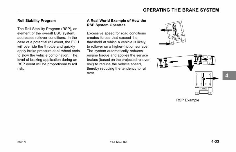
OPERATING THE BRAKE SYSTEM
Roll Stability Program
The Roll Stability Program (RSP), anelement of the overall ESC system,addresses rollover conditions. In thecase of a potential roll event, the ECUwill override the throttle and quicklyapply brake pressure at all wheel endsto slow the vehicle combination. Thelevel of braking application during anRSP event will be proportional to rollrisk.
A Real World Example of How theRSP System Operates
Excessive speed for road conditionscreates forces that exceed thethreshold at which a vehicle is likelyto rollover on a higher-friction surface.The system automatically reducesengine torque and applies the servicebrakes (based on the projected rolloverrisk) to reduce the vehicle speed,thereby reducing the tendency to rollover.
RSP Example
(03/17) Y53-1203-1E1 4-33
4

OPERATING THE BRAKE SYSTEM
Yaw Stability
Yaw stability counteracts the tendencyof a vehicle to spin about its verticalaxis. During operation, if the frictionbetween the road surface and the tiresis not sufficient to oppose lateral (side)forces, one or more of the tires canslide, causing the truck/tractor to spin.
These yaw events are referred to aseither "under-steer" (where there is alack of vehicle response to steeringinput due to tire slide on the steer axle)or "over-steer" (where the tractor'srear end slides out due to tire slideon the rear axle) situation. Generally,shorter wheelbase vehicles (tractors,for instance) have less natural yawstability, while longer wheelbasevehicles (straight trucks, for instance)have greater natural yaw stability.Factors that influence yaw stabilityare: wheelbase, suspension, steeringgeometry, weight distribution front torear, and vehicle track width.
Yaw Control
Yaw Control responds to a widerange of low- to high-friction surfacescenarios including rollover, jackknifeand loss of control. In the case ofvehicle slide (over-steer or understeersituations), the system will reduce thethrottle and then brake one or moreof the "four corners" of the vehicle(in addition to potentially applyingthe trailer brakes), thus applying acounter-force to better align the vehiclewith an appropriate path of travel. Forexample, in an over-steer situation,the system applies the "outside"front brake; while in an under-steercondition, the "inside" rear brake isapplied.
A Real World Example of How YawControl Operates
Excessive speed exceeds thethreshold, creating a situation where avehicle is likely to spin and jackknife.
The Yaw Control system reducesengine throttle and selectively appliesbrakes to reduce the vehicle speed,thereby reducing the tendency tojackknife.
Yaw Control Example
4-34 Y53-1203-1E1 (03/17)
4

OPERATING THE BRAKE SYSTEM
Automatic Traction Control
Your truck/tractor ABS has anautomatic traction control (ATC)feature. This feature is controlled bya switch. This feature is monitored bya warning lamp located on the switch.The Traction Control warning lamp willbriefly illuminate and then go out whenthe ignition switch is first turned on.The traction control warning lamp willilluminate whenever the ATC systemdetects drive wheel spin. The lamp willremain illuminated as long as wheelspin is detected and the ATC systemis applying the drive wheel brakesor reducing engine torque. Enginetorque or vehicle speed should bereduced to eliminate wheel spin andprevent excessive application of theATC system.
Except for checking for properillumination of the ABS and tractioncontrol warning lamps when firststarting the vehicle, and for monitoringthese lamps while driving, no specialoperating procedures are required.For detailed system description, seeliterature for your specific ABS thatwas provided with your vehicle.
This feature helps improve tractionwhen vehicles are on slippery surfacesor surfaces with poor traction (i.e.mud or snow) by reducing drive wheeloverspin. Automatic traction controlworks automatically in two differentways:
• If a drive wheel starts to spin,ATC applies air pressure to brakethe wheel. This transfers enginetorque to the wheels with bettertraction.
• If all drive wheels spin, ATCreduces engine torque to provideimproved traction.
ATC turns itself on and off, you donot have to select this feature. Ifdrive wheels spin during acceleration,the ATC Warning Lamp comes on,indicating wheel spin control is active.Do not allow the ATC Warning Lampto remain on continuously for anextended length of time. Extended,continuous use of the ATC can causeoverheating of the drive wheel brakes.
(03/17) Y53-1203-1E1 4-35
4
OPERATING THE BRAKE SYSTEM
Deep Snow and Mud Switch
A deep snow and mud switch isincluded with ATC. The Deep Snowand Mud feature is helpful duringacceleration. This function increasesavailable traction on extra soft surfaceslike snow, mud or gravel, by slightlyincreasing the permissible wheel spin.When this function is in use, the ATCWarning Lamp blinks continuously.
Off-Road ABS Function Switch(option)
Your vehicle may be equipped witha separate switch to activate anOff-Road ABS function. This functionis NOT to be used for On-Highwaydriving but is intended to be usedto improve stopping performance inOff-Highway conditions (e.g., loosegravel and mud). The Off-Road ABSfunction is accomplished by allowing a"wedge" of material to build-up in frontof momentarily locked wheels.
1. Changes the ABS control limits toallow for a more aggressive ABSfunction while off-road.
2. Improves vehicle control andhelps reduce stopping distancesin off-road conditions or on poortraction surfaces such as loosegravel, sand, and dirt.
3. Allows retarders to functionindependently of the ABS function.
4. If your vehicle does not have anengine retarder, the Off-Road ABSswitch will function the same.
WARNING!While the off roadmode can improvevehicle control and shorten stoppingdistances, some steering ability maybe reduced on certain surfaces re-sulting from the momentarily slidingtires. Always operate your vehicle atsafe operating speeds. Failure to doso may cause you to lose control ofthe vehicle and could result in an ac-cident or personal injury.
4-36 Y53-1203-1E1 (03/17)
4
OPERATING THE BRAKE SYSTEM
CAUTIONNever drive your vehicle on im-proved roads/highways with theOff-Road ABS function turned on.When you drive your vehicle onto animproved road surface or highway,immediately turn off the Off-RoadABS switch. Failure to do so willcause the ABS system to not func-tion properly in an ABS event under25 mph (40 km/h) and could resultin an accident or personal injury.
The ABS lamp flashes slowly duringoff-road mode engagement. This isdone to alert you of a modification tothe ABS control software. At speedsabove 25 mph (40 km/h), the ABScontroller operates in the normalon-highway mode. At speeds between10 and 25 mph (16 and 40 km/h), theABS control software is modified toallow short periods (0.25 seconds)of locked- wheel cycles. At speeds
below 10 mph (16 km/h), the ABScontrol software is turned off to allowlocked wheels. When the Off-RoadABS function is enabled, the RetarderDisable output is turned off. Thatis, the engine retarders are left tofunction without ABS intervention.For additional information, see theOff-Road ABS pamphlet in yourvehicle’s glove box.
Effectiveness and Limitations
ESC is designed and optimized fortrucks and for tractors that tow singletrailers. If a tractor equipped withESC is used to power multiple trailercombinations (known as "doubles" or"triples") the effectiveness of the ESCmay be greatly reduced.
WARNING!Exercise extreme care when tow-ing doubles or triples with a vehicleequipped with Electronic StabilityProgram. Excessive speed andaggressive maneuvers, such assharp turns, sudden steering inputsor abrupt lane changes should beavoided because these maneuverscould cause loss of vehicle controlpossibly resulting in an accident in-volving death or personal injury.
(03/17) Y53-1203-1E1 4-37
4

OPERATING THE BRAKE SYSTEM
Additionally, the ESC system’seffectiveness may be greatly reducedif:
• The load shifts due to improperretention, accident damage or theinherently mobile nature of someloads (for example, hanging meat,live animals or partially ladentankers).
• The vehicle has an unusually highor off-set center of gravity (CG).
• One side of the vehicle drops offthe pavement at an angle that istoo large to be counteracted by areduction in speed.
• The vehicle is used to haul doubleor triple trailer combinations.
• If very rapidly winding steeringinputs are inputted at high speeds.
• There are mechanical problemswith suspension leveling of the
tractor or trailer resulting in unevenloads.
• The vehicle is maneuvering on ahigh banked road creating eitheradditional side forces due to theweight (mass) of the vehicle or adeviation between expected andactual yaw rates.
• Gusty winds are strong enoughto cause significant side forceson the vehicle and any towedvehicles.
To maximize the effectiveness of ESC:
• Loads must be properly securedand evenly distributed at all times.
• Drivers need to exercise extremecaution at all times, and avoidsharp turns, sudden steeringinputs or abrupt lane changes athigh speeds, particularly if:
° The vehicle hauls loads thatcould shift,
° The vehicle or load has a highor off-set center of gravity(CG) when loaded, or
° The vehicle tows doubles ortriples.
The ESC system was specificallycalibrated and validated only foryour vehicle’s original factory-builtconfiguration. If your vehicle’s chassiscomponents are altered (for example;a wheelbase extension or reduction,tag axle addition or removal, tractor totruck conversion or steering systemcomponent change) the ESC systemmust be disabled immediately by aqualified mechanic.
4-38 Y53-1203-1E1 (03/17)
4
OPERATING THE BRAKE SYSTEM
WARNING!Failure to disable ESC "ElectronicStability Control" when modifying avehicle could result in a loss of ve-hicle control possibly resulting in anaccident involving death or personalinjury.
WARNING!For vehicles equipped with ESC"Electronic Stability Control" do notreplace the vehicle’s steering wheelwith an aftermarket or different partnumber than originally supplied. Us-ing a different steering wheel couldcause ESC to malfunction causinga loss of vehicle control possiblyresulting in an accident involvingdeath or personal injury.
Whenever maintenance or repairwork is performed to the steeringmechanism, linkage, gear, adjustmentof the wheel track, or if the steering
angle sensor is replaced or the steeringwheel is changed or re-centered, theSteering Angle Sensor must bere-calibrated.
WARNING!If the Steering Angle Sensor is notrecalibrated, the Yaw Control sys-tem will not function properly. A un-calibrated sensor could result in aloss of control of your vehicle whichcan lead to an accident involvingdeath or personal injury.
Trailer Brake Hand Valve
This hand valve provides air pressureto apply the trailer brakes only. Itoperates independently of the foottreadle valve.
To operate the trailer brake handvalve:
• Pull down on the lever under theright side of the steering wheel.See Steering Column And Mirrorson page 3-117.
• The valve is self-returning. Whenpressure is removed from thevalve lever, it will return to the OFFposition.
NOTEThe trailer brake is not to be used asa substitute for the service brakes.Using this brake frequently, insteadof using the foot brake, will cause thetrailer brakes to wear out sooner.
(03/17) Y53-1203-1E1 4-39
4
OPERATING THE BRAKE SYSTEM
WARNING!Do not use the trailer hand brake orservice brakes to park and hold anunattended vehicle, use the parkingbrakes. Because service brakeswork with air pressure, these brakescould slowly release. Your vehiclecould roll, causing a serious ac-cident. Never rely on the servicebrakes to hold a parked vehicle.Failure to comply may result in per-sonal injury, death, equipment orproperty damage.
Driving with an UnloadedTrailer
Do not use the engine retarder (suchas an exhaust brake) to slow thevehicle down when you are pulling anempty trailer.
WARNING!Do not use an engine retarder whenyou are driving with an unloadedtrailer. Using engine retarders withan unloaded trailer can cause awheel lockup resulting in less con-trol and/or jackknife. When youare unloaded, you can have a se-rious accident if your wheels locksuddenly during braking. Failure tocomply may result in personal injury,death, equipment or property dam-age.
Engine Retarders
WARNING!The engine retarder isNOT intendedas the primary brake for the vehi-cle, nor is it an emergency brake.The engine retarder only helps theservice brakes by using pressure toslow the drivetrain. Use the servicebrakes for quick stops. DO NOT relyonly on the engine retarder. Fail-ure to comply may result in personalinjury, death, equipment or propertydamage.
4-40 Y53-1203-1E1 (03/17)
4
OPERATING THE BRAKE SYSTEM
WARNING!Do not operate the engine retarderwhen driving/operating your vehicleon road surfaces with poor traction(wet, icy, or snow covered roads)or in heavy traffic. Braking causedby the normal operation of the en-gine retarder could cause you to losecontrol of the vehicle resulting in anaccident. Failure to comply may re-sult in personal injury, death, equip-ment or property damage.
NOTEThe exhaust brake and engine brakeare two types of engine retarders.See your Engine Operation andMaintenance Manual and EngineRetarder or Engine Brake OperationManual for further details on usingthese types of engine retarders.
A variety of engine retarders orexhaust brakes may be installed (as
an option) to create a braking effecton the drive wheels. These devicesuse your engine's power to slow yourvehicle down. Because they canhelp keep your vehicle's brakes fromoverheating, they save wear and tearon the service brakes. However, theretarder is not an emergency brake.
Ideally (on normal road surfaces),you should slow your vehicle withthe retarder (where permitted by law)and use the service brakes only forstopping completely. Operating thisway will greatly prolong the life of thebrakes.
Exhaust Brake
With the exhaust brake switch ON, thebrake automatically creates its brakingeffect when you remove your foot fromthe accelerator pedal.
The brake switch is located on theaccessory dash panel. It controlswhether the brake is ON (ready to slowthe vehicle down) or OFF (no brakingaction).
• Do not use the engine retarder(such as an exhaust brake) toslow the vehicle down when youare pulling an empty trailer. SeeEngine Brakes for further details.
(03/17) Y53-1203-1E1 4-41
4
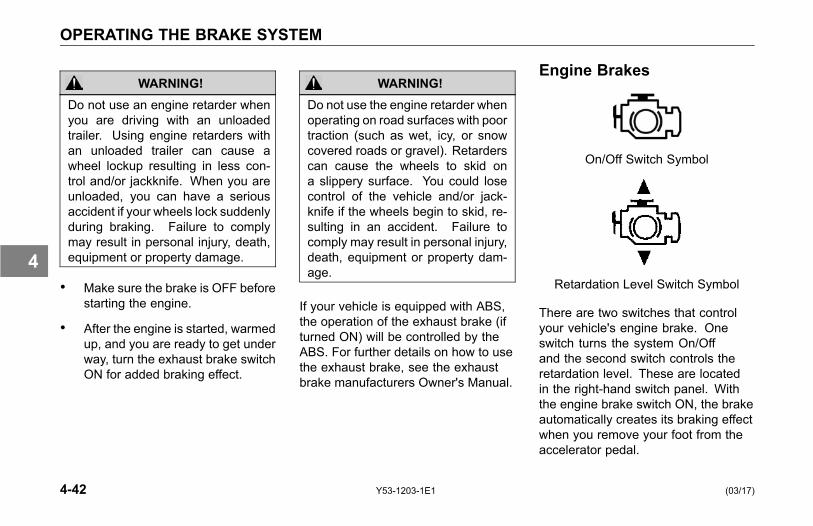
OPERATING THE BRAKE SYSTEM
WARNING!Do not use an engine retarder whenyou are driving with an unloadedtrailer. Using engine retarders withan unloaded trailer can cause awheel lockup resulting in less con-trol and/or jackknife. When you areunloaded, you can have a seriousaccident if your wheels lock suddenlyduring braking. Failure to complymay result in personal injury, death,equipment or property damage.
• Make sure the brake is OFF beforestarting the engine.
• After the engine is started, warmedup, and you are ready to get underway, turn the exhaust brake switchON for added braking effect.
WARNING!Do not use the engine retarder whenoperating on road surfaces with poortraction (such as wet, icy, or snowcovered roads or gravel). Retarderscan cause the wheels to skid ona slippery surface. You could losecontrol of the vehicle and/or jack-knife if the wheels begin to skid, re-sulting in an accident. Failure tocomply may result in personal injury,death, equipment or property dam-age.
If your vehicle is equipped with ABS,the operation of the exhaust brake (ifturned ON) will be controlled by theABS. For further details on how to usethe exhaust brake, see the exhaustbrake manufacturers Owner's Manual.
Engine Brakes
On/Off Switch Symbol
Retardation Level Switch Symbol
There are two switches that controlyour vehicle's engine brake. Oneswitch turns the system On/Offand the second switch controls theretardation level. These are locatedin the right-hand switch panel. Withthe engine brake switch ON, the brakeautomatically creates its braking effectwhen you remove your foot from theaccelerator pedal.
4-42 Y53-1203-1E1 (03/17)
4

OPERATING THE BRAKE SYSTEM
Depending on the engine, yourvehicle may be equipped with eithera 2-position or 3-position RetardationLevel Switch. If your vehicle has thetwo-speed system, you can selectFULL or HALF. If it has the three-speedsystem, you can select LOW (1),MEDIUM (2), or HIGH (3) retarding.
See your Engine Operation andMaintenance Manual or Engine BrakeOperation Manual for further details onusing engine retarders.
Brake Components
The following is a brief description ofthe air/brake system. It is intended tosupply you with general information onhow the system works.
Compressor: supplies air to thesystem. System pressure is controlledby the governor.
Governor: controls the air pressurein the system by actuating thecompressor discharge mechanism. Itscut-out pressure is 115 to 125 psi (793to 862 kPa). Its preset cut-in pressureis set to between 13 to 25 psi (90 to172 kPa) below the cut-out pressuresetting (cut-out and cut-in interval isnot adjustable).
Safety Valve: installed on the supplyair tank outlet. It should vent off at 150psi (1034 kPa) permitting air to escape.
Air Dryer: collects and removesmoisture and contaminants from theair as it travels from the compressorto the wet tank.
Compressed Air Tanks: The wettank receives air from the air dryer andcools it somewhat, allowing moistureto condense for draining. Relativelydry air is then supplied to the twoservice air tanks for distribution to theirrespective brake circuits. The serviceair tanks are isolated from each otherby check valves.
Dual Service Brake Treadle Valve:delivers air to the two service brakecircuits.
Double Check Valve: directs thehigher air pressure from either the rear(primary) or front (secondary) serviceair tank to the modulating valve.
(03/17) Y53-1203-1E1 4-43
4
OPERATING THE BRAKE SYSTEM
Modulating Valve (SR-1): used onlyon full trucks, not tractors, performsfour functions:
• Limits spring brake hold-off airpressure delivered to the springbrake chambers.
• Provides a quick release of airpressure from the spring brakechambers to speed spring brakeapplication.
• Modulates spring brake applicationin proportion to front serviceapplication in the event of a rearservice failure.
• Prevents compounding of serviceand spring applications.
Quick-Release Valve: speeds therelease of air from the brake chambers.When air is released, the air in thebrake chambers is exhausted atthe quick-release valve, rather than
exhausting back through the treadlevalve.
Single Check Valve: allows air flow inone direction only.
Parking Brake Valve: Yellowdiamond-shaped knob. It controls theapplication and release of the parking(spring) brakes of the vehicle or of thevehicle-trailer combinations. If the airsystem is being charged from zeropressure, the parking brake valve willnot hold in the release position until thesystem pressure exceeds 60 psi (414kPa), which is the pressure required tooverride the load of this valve's plungerreturn spring.
Trailer Supply Valve: The Redoctagonal-shaped knob protectsthe vehicle system; it functions inconjunction with the parking brakevalve (yellow). The trailer supplyvalve is responsible for synchronizingthe vehicle and trailer parking and
emergency brakes. If the air systemis being charged from zero pressure,the trailer supply valve will not hold inthe applied position until the systempressure exceeds 50 psi (345 kPa). Itautomatically pops out and exhaustsair if supply air pressure drops below60 psi (414 kPa).
Vehicle Protection Valve: Thefunctions of this valve are to (1) receiveall pneumatic signals pertinent to theoperation of the trailer brake system,(2) transmit these signals to the trailer,and (3) protect the vehicle air supplyin case of separation of the air linesconnecting the vehicle to the trailer.
4-44 Y53-1203-1E1 (03/17)
4
OPERATING THE ENGINE
OPERATING THEENGINE
Introduction
For detailed information on startingand operating the engine, refer to theEngine Operation and MaintenanceManual provided with your Kenworth.
Because each vehicle iscustom-equipped, all engine operationinstructions presented in this sectionare general. You will want to consultthe engine manual to find out detailsabout your vehicle's specific engineneeds. You may need to use a slightlydifferent procedure from the oneoutlined here.
Also, read the American TruckingAssociation's (ATA) Truck Driver'sHandbook. It will give you tips onstarting, shifting, and driving yourvehicle.
This section includes instructions forboth Normal Temperature starting andCold Weather starting. The enginetype (brand) and size determines whattype of cold weather starting aid isinstalled in your vehicle. Refer to yourEngine Operation and MaintenanceManual to learn what precautionsyou should take before starting theengine. Many new electronic enginescannot use ether or other startingfluids. These engines are equippedwith a flame-start air intake heatingsystem. See Starting Procedure - ColdWeather on page 4-47.
WARNING!Do not start or let the engine run inan enclosed, unventilated area. Ex-haust fumes from the engine containcarbon monoxide, a colorless andodorless gas. Carbon monoxide canbe fatal if inhaled. Failure to com-ply may result in personal injury ordeath.
WARNING!Do not use ether or starting fluid inconjunction with flame-start air in-take heating systems. Flame-startsystems use an open flame insidethe manifold to heat the air/fuel mix-ture for cold weather starting. Ifether is also used with flame-start,the air/fuel will ignite inside the man-ifold, which could cause an explo-sion. Failure to comply may resultin personal injury, death, equipmentor property damage.
CAUTIONDo not park or operate the vehicle inareas where the hot exhaust systemmay come in contact with dry grass,brush, spilled fuel or other materialthat can cause a fire.
(03/17) Y53-1203-1E1 4-45
4
OPERATING THE ENGINE
Starting Procedure - NormalTemperature
When the outside temperature isabove 50° F (10° C), you can use thefollowing procedure:
1. Set the parking brake.
2. Put your main transmission inNeutral.
3. Disengage (depress) the clutch(with manual transmission).
4. Turn the key switch to ON.
CAUTIONNever operate the starter motor whilethe engine is running. The starterand flywheel gears could clash orjam, severely damaging them.
NOTESome starters are equipped withovercrank protection. Check the"Engine Operation and MaintenanceManual" for details.
5. Turn the ignition key to the STARTposition. If the engine does notstart within 30 seconds, releasethe ignition switch. To avoidovertaxing the starter motor orthe batteries, don’t use the starterfor more than 30 seconds. Letthe starter motor cool and thebatteries recover for two minutesbefore trying again.If the engine still won’t start after acouple of tries, check the fuel linesfor possible fuel starvation or airleaks. Starting failure may meanfuel isn’t reaching the injectors.
6. As soon as the engine starts, beginto watch the oil pressure gauge.Check your engine manufacturer’s
manual for the right pressure foryour engine. If the oil pressuredoesn’t rise within a few seconds,stop the engine. Find out whatis wrong before restarting theengine.
7. Slowly engage (release) the clutchafter the engine has started.
8. Wait for the oil pressure gauge toreach normal operating pressurebefore operating the vehicle oridling faster than 1000 rpm.
4-46 Y53-1203-1E1 (03/17)
4
OPERATING THE ENGINE
Starting Procedure - ColdWeather
In cold weather, fast engine startinghelps relieve the loads on the electricalsystem and cranking motor. Using thespecial cold starting equipment willhelp starting. If you follow a few simpleguidelines, you will extend the servicelife of your engine:
• Keep the electrical system in topcondition.
• Use the best quality fuel of therecommended grade.
• Use recommended enginelubricating oil.
• For manual transmissions andauxiliary transmissions, leave thetransmission in neutral and allowthe transmission lubricating oilto warm up (approximately 3-5minutes) before operating vehicle.
Engine Block and Oil PanHeater (Option)
To preheat the engine before starting,plug the optional engine block heaterinto a properly grounded AC electricalsource. Do not start the engine withthe heater plugged in.
WARNING!Engine block and oil pan heaterscan cause fires which may result indeath, injury and/or property dam-age if not properly maintained andoperated. Regularly inspect the en-gine block heater wiring and connec-tor for damaged or frayed wires. Donot use the heater if there are anysigns of problems. Contact your au-thorized dealer or the manufacturerof the heater if you are in need of re-pairs or information.
CAUTIONAlways unplug heater before startingthe engine. Damage to the coolingsystem could occur if the heater isnot turned OFF (unplugged).
Depending on engine make, when thetemperature falls below -10° F (-24°C), the block heater is recommended.
• Use a solution of half ethyleneglycol antifreeze and half water forbest heater performance. Do notexceed 65 percent concentrationof antifreeze, as a shortenedheater life will result. See EngineCooling System on page 5-65, formore information.
• After servicing the cooling system,operate the vehicle for a day or twobefore using the heater. Trappedair inside the engine needs timeto escape.
(03/17) Y53-1203-1E1 4-47
4
OPERATING THE ENGINE
Engine Warm-upEngine
The purpose of engine warm-up is toallow oil film to be established betweenpistons and liners, shafts and bearingswhile your engine gradually reachesoperating temperature.
Warm-up Procedure
1. After you’ve started your engine,idle it at approximately 600 RPMwhile you check:
a. oil pressure
b. air pressure
c. alternator output
2. After a few minutes of idling at600 RPM, increase your idlespeed to 900 or 1000 RPM.Continue your warm-up. Thisprocedure allows oil to warm andflow freely while pistons, liners,shafts, and bearings expand
slowly and evenly. In extremelycold temperatures, you may haveto increase idle speed.
NOTEIn colder climates where the tem-perature is often below freezing,the warm-up for turbocharged en-gines is especially important. Chilledexternal oil lines leading to the tur-bocharger will slow the oil flow untilthe oil warms, reducing oil availablefor the bearings. Watch the engineoil temperature or pressure gaugefor a warming trend before increas-ing engine idle speed (RPM).
3. Continue the engine warm-up untilthe coolant temperature reachesat least 130° F (54° C). At thistemperature, you can use partialthrottle. Wait until the coolanttemperature is at least 160° F (71°C) before operating at full throttle.
WARNING!Exhaust fumes from the enginecontain carbon monoxide, a color-less and odorless gas. A poorlymaintained, damaged, or corrodedexhaust system can allow car-bon monoxide to enter the cab orsleeper. Failure to properly main-tain your vehicle could cause car-bon monoxide to enter the cab andcause death or personal injury.
WARNING!Never idle your vehicle for prolongedperiods of time if you sense that ex-haust fumes are entering the cab.Investigate the cause of the fumesand correct it as soon as possible.If the vehicle must be driven underthese conditions, drive only with thewindows slightly open. Failure to re-pair the source of the exhaust fumesmay lead to death or personal injury.
4-48 Y53-1203-1E1 (03/17)
4
OPERATING THE ENGINE
CAUTIONThe use of a winterfront can resultin excessive engine coolant, oil, andcharge air (intake) temperatures,which can lead to overheating andpossible engine damage. If youmust use a winterfront:
• Refer to the "Engine Operationand Maintenance Manual"for operating restrictions andrecommendations.
• Use only a winterfrontavailable from your dealerthat is compatible with anEPA-compliant engine coolingsystem. These winterfronts arespecifically designed for use withnew grill snap patterns.
NOTEKeep the engine exhaust systemand the vehicle’s cab/sleeper venti-lation system properly maintained.It is recommended that the vehicle’sexhaust system and cab/sleeper beinspected:
• By a competent technician every15,000 miles,
• Whenever a change is noticed inthe sound of the exhaust system,
• Whenever the exhaust system,underbody, cab or sleeper isdamaged.
NOTE• Do not stay in the vehicle with
the engine running or idlingfor more than 10 minutes withthe vehicle’s Heater and A/Cventilation system in RECIRCor at LOW FAN SPEED. Evenwith the ventilation system On,running the engine while parkedor stopped for prolonged periodsof time is not recommended.
• If other vehicles are parked nextto you idling, move your vehicleor do not stay in your vehicle forprolonged periods of time.
Idling the Engine
Under most circumstances, idlingyour engine for long periods merelywastes fuel. In severe arctic weatherconditions, however, you may needlonger idling to be sure all parts of yourengine are fully lubricated.
(03/17) Y53-1203-1E1 4-49
4
OPERATING THE ENGINE
WARNING!To reduce the chance of death orpersonal injury and/or vehicle dam-age from overheated engines, whichcan result in a fire, never leave theengine idling without an alert driverpresent. If the engine should over-heat, as indicated by the enginecoolant temperature light, immedi-ate action is required to correct thecondition. Continued unattendedoperation of the engine, even fora short time, may result in seriousengine damage or a fire.
CAUTIONDo not allow your engine to idle,at low rpm's (400–600 rpm), longerthan five minutes. Long peri-ods of idling after the engine hasreached operating temperaturescan decrease engine temperatureand cause gummed piston rings,clogged injectors, and possible en-gine damage from lack of lubrica-tion. The normal torsional vibrationsgenerated can also cause transmis-sion wear.
Transmission
In cold weather [below 32° F (0°C)], you may find shifting sluggishwhen you first start up. Transmissionwarm-up is especially important atthis time, but it is always a goodidea to warm-up your transmissionbefore starting out on the road. Towarm-up the transmission, follow theseprocedures.
To warm-up the transmissionlubricating oil during engine warm-up,with a single transmission (manual andautomatic):
1. Put the transmission in Neutral.
2. Release the clutch pedal (manualonly) and operate the transmissionin neutral for 3 to 5 minutes priorto operating the transmission ineither forward or reverse range.
3. If you have a two-transmissioncombination:
4-50 Y53-1203-1E1 (03/17)
4
OPERATING THE ENGINE
a. Put the main transmission ingear.
b. Put the auxiliary transmissionin Neutral. This will allowthe transmission countershaftto turn, agitating the oil andwarming it.
Ether Metering Equipment
WARNING!Ether starting fluid is flammableand poisonous. Do not smoke nearether or ether equipment, do notingest ether fluid and wear safetygoggles when handling ether fluid.Follow all safety literature providedwith your ether equipment. Failureto take these precautions may resultin death, personal injury.
WARNING!Do not move or relocate the ethercylinder or tubing from its original in-stallation. It must bemounted to pro-tect it from engine exhaust heat andfrom moving parts which could dam-age it. Failure to comply may resultin death, personal injury, equipmentor property damage.
WARNING!Do not store the spare cylinder in thecab. Failure to comply may result indeath, personal injury, equipment orproperty damage.
Do not smoke when testing, installing,or servicing an ether starting unit.Service it in a well-ventilated area awayfrom heat, open flames, or sparks.
If swallowed, do not induce vomiting.Call a physician immediately.
Wear goggles to avoid getting fluid inyour eyes. Avoid getting it on your skinand avoid breathing the fumes. If fluiddoes get in your eyes or fumes irritateyour eyes, flush for 15 minutes withlarge amounts of clean water. Contactan eye specialist.
In warm weather, when you will notneed the ether starting system, removethe ether bottle from your truck and
(03/17) Y53-1203-1E1 4-51
4

OPERATING THE ENGINE
store it safely. Return the protectivecap to the bottle mounting connector.
For more helpful starting information,refer to the engine manual that camewith your vehicle.
Ether injected into the engine cylinderduring cold weather startup will helpthe engine start faster. Using etherduring cold weather startup will resultin reduced demands on the batteriesand the starter motor.
When you turn the ignition switch to theSTART position, the cranking motorand the ether system are engaged.When needed, starting fluid is releasedfrom a pressurized cylinder, flowsthrough a valve and tubing, and spraysfrom a nozzle in you engine’s air intakesystem.
Cruise Control
If your vehicle is equipped with cruisecontrol dash switches, follow theoperating instructions below.
WARNING!Do not operate the cruise controlwhen driving on road surfaces withpoor traction (wet, icy, or snowcovered roads) or in heavy traffic.Accelerations caused by the normaloperation of the cruise control couldcause you to lose control of the ve-hicle resulting in an injury accident.Failure to comply may result in per-sonal injury, death, equipment orproperty damage.
On/Off Switch, Set/Resume Switch
4-52 Y53-1203-1E1 (03/17)
4
OPERATING THE ENGINE
Using Cruise Control While Driving:
Setting Cruise Speed
1. Ensure that the vehicle speed isabove the minimum cruise controlspeed and the engine speed isabove 1100 rpm.
2. Move the ON/OFF switch to the"ON" position.
3. Accelerate the vehicle to thedesired cruise speed.
4. Toggle the SET/RESUME switchto the "SET" position to set thecruise speed.
NOTECruise Control may not hold the setspeed going down hills. If the speedincreases going down a hill, use thebrakes to slow down. This will can-cel Cruise Control.
Changing the Cruise Set Speed
• To increase the cruise set speed;Hold the SET/ RESUME switch inthe "SET" position until the desiredspeed is achieved then releasethe switch.
• To decrease the cruise set speed;Hold the SET/ RESUME switch inthe "RESUME" position and coastto the desired lower speed thenrelease the switch.
Cancelling Cruise Control
You can cancel cruise control in anyof these ways:
• Tap the brake pedal.
• Tap the clutch pedal.
• Move the ON/OFF switch to the"OFF" position.
Resuming Cruise Control
1. If you tapped the brake orclutch pedal, the cruise/idlecontrol remembered thepreviously set cruise speed.To resume that set speed,accelerate above the minimumcruise control speed and;Toggle the SET/RESUME switchto the "RESUME" position.
2. If you moved the ON/OFF switchto the "OFF" position or turned theignition key OFF, this cleared thesystem memory and you will needto set a new cruise speed.
(03/17) Y53-1203-1E1 4-53
4

OPERATING THE ENGINE
Using Cruise Control for StationaryPTO Operation:
Setting Idle Speed
1. Ensure parking brakes are applied.
2. Ensure transmission is in Neutral.
3. Engage PTO per themanufacturer's operatinginstructions.
4. Move the ON/OFF switch to the"ON" position.
5. Toggle the SET/RESUME switchto obtain the desired engine rpm.
Engine Fan Control
The engine fan can be turned ONusing a switch that is mounted on theaccessory switch panel. This lets youset the fan to manual or automaticoperation.
• With the ignition key turned ONand the fan switch in the MANUALposition, the engine fan will be ONregardless of engine temperature.
• With the engine fan switch inthe AUTO position, the enginefan will automatically turn ONwhen any one of the followingconditions occur: 1) the enginecoolant temperature reaches 200ºF (93º C) approximately, 2) theAir Conditioning system is turnedON or has reached a set pressure
point, or 3) the Engine Control Unitdetects that air intake temperature,oil temperature, or compressionbrake usage requires it.
WARNING!Do not work on or near the fan withthe engine running. Anyone near theengine fan when it turns on couldbe injured. If it is set at MANUAL,the fan will turn on any time the ig-nition key switch is turned to the ONposition. In AUTO, it could engagesuddenly without warning. Beforeturning on the ignition or switchingfrom AUTO to MANUAL, be sure noworkers are near the fan. Failure tocomply may result in personal injury,death, equipment or property dam-age.
4-54 Y53-1203-1E1 (03/17)
4
OPERATING THE ENGINE
CAUTIONThe fan or equipment near it couldbe damaged if the fan turns on sud-denly when you do not expect it.Keep all tools and equipment awayfrom the fan.
NOTEDo not operate the engine fan inthe MANUAL position for extendedperiods of time. The fan hub wasdesigned for intermittent operation.Sustained operation will shorten thefan hub's service life as well as re-duce fuel economy.
Engine Control Display
Your Kenworth may come withan optional Engine and DriverInformation Display. This instrumentrecords information on enginediagnostics, scheduled maintenance,driving conditions, and general tripinformation. The specific featuresof your display may vary dependingon engine make. For completeinformation on the display see theengine manufacturer's manual.
Engine Shutdown System
This system is an option with eachengine. The engine shutdown systemcontinually monitors oil pressure andengine temperature. If either conditionchanges beyond the normal range ofoil pressure or temperature readings,the engine shuts down automatically,sounding the alarm and turning awarning light on. The buzzer will soundcontinuously as long as Stop Engineindicator is on.
After the engine starts, and until oilpressure reaches normal operatingpressures, a warning alarm will sound.As soon as oil pressure increases, thebuzzer turns off automatically. If theengine shuts down automatically or ifthe buzzer and light turn on while theengine is running, have your engineserviced at an authorized KenworthDealer.
(03/17) Y53-1203-1E1 4-55
4
OPERATING THE ENGINE
Each shutdown system is enginespecific; therefore to learn howthis system works on your vehicle,you should consult the enginemanufacturer's manual.
4-56 Y53-1203-1E1 (03/17)
4

OPERATING THE REAR/DRIVE AXLE
OPERATING THEREAR/DRIVE AXLE
Introduction
This section covers the operationof your Rear/Drive Axle. Theseinstructions apply to the most commonfeatures of drive axles. Refer to themanufacturers instructions for furtherinformation on the operation of youraxle.
Inter-Axle Differential Lock
The inter-axle differential allows eachaxle to turn independently, whichrelieves stress on the rear axles andreduces tire wear. A switch on theaccessory switch panel locks theinter-axle differentials, which gives youbetter traction for slippery surfaces.You will notice that the switch has aguard to protect you from activating itaccidentally.
When to Use the Differential Lock
In the LOCK position, an air operatedclutch positively locks both sets ofaxles together, providing greatertraction on slippery road surfaces;however, steering around cornersand on dry pavement is more difficult.Continuous operation on a paved, drysurface stresses the tandem axles,possibly causing internal damage.
Only use this feature when driving onsurfaces with poor traction, such asheavy mud or snow, or loose gravel.And do not use it when going downhillor at speeds greater than 25 mph (40km/h).
Lock the differential when youencounter road conditions such asthese:
• Ice or snow, with or without tirechains.
• Dirt roads.
(03/17) Y53-1203-1E1 4-57
4
OPERATING THE REAR/DRIVE AXLE
• Loose sand, mud, or other off-roadconditions.
WARNING!Do not put the differential lock in theLOCK position while the wheels arespinning freely (slipping), you couldlose control of the vehicle or causeaxle damage. Switch to LOCK onlywhen the wheels are not spinning.Failure to comply may result in per-sonal injury, death, equipment orproperty damage.
• Look ahead for wet, muddy, or icypatches on the road, stop yourvehicle and switch to LOCK aheadof time.
WARNING!Do not operate the vehicle ondry pavement with the differentiallocked, this could lead to an acci-dent. On dry pavement, you will notbe able to steer well with the differ-ential locked. Lock the differentialonly when operating on surfaceswith poor traction, such as wet, slip-pery roads or loose gravel. Failureto comply may result in personalinjury, death, equipment or propertydamage.
Inter-Axle Differential LockOperation
WARNING!Do not use the differential lock dur-ing downhill operation or at speedsabove 25 mph (40 km/h). When itis engaged under these conditions,your vehicle will exhibit understeerhandling characteristics. This un-dersteer condition will cause yourvehicle to not turn as quickly andmore steering effort will be required,which can cause an accident. Fail-ure to comply may result in personalinjury, death, equipment or propertydamage.
4-58 Y53-1203-1E1 (03/17)
4
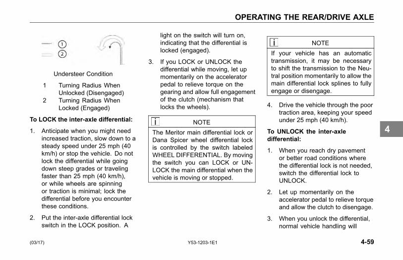
OPERATING THE REAR/DRIVE AXLE
Understeer Condition
1 Turning Radius WhenUnlocked (Disengaged)
2 Turning Radius WhenLocked (Engaged)
To LOCK the inter-axle differential:
1. Anticipate when you might needincreased traction, slow down to asteady speed under 25 mph (40km/h) or stop the vehicle. Do notlock the differential while goingdown steep grades or travelingfaster than 25 mph (40 km/h),or while wheels are spinningor traction is minimal; lock thedifferential before you encounterthese conditions.
2. Put the inter-axle differential lockswitch in the LOCK position. A
light on the switch will turn on,indicating that the differential islocked (engaged).
3. If you LOCK or UNLOCK thedifferential while moving, let upmomentarily on the acceleratorpedal to relieve torque on thegearing and allow full engagementof the clutch (mechanism thatlocks the wheels).
NOTEThe Meritor main differential lock orDana Spicer wheel differential lockis controlled by the switch labeledWHEEL DIFFERENTIAL. By movingthe switch you can LOCK or UN-LOCK the main differential when thevehicle is moving or stopped.
NOTEIf your vehicle has an automatictransmission, it may be necessaryto shift the transmission to the Neu-tral position momentarily to allow themain differential lock splines to fullyengage or disengage.
4. Drive the vehicle through the poortraction area, keeping your speedunder 25 mph (40 km/h).
To UNLOCK the inter-axledifferential:
1. When you reach dry pavementor better road conditions wherethe differential lock is not needed,switch the differential lock toUNLOCK.
2. Let up momentarily on theaccelerator pedal to relieve torqueand allow the clutch to disengage.
3. When you unlock the differential,normal vehicle handling will
(03/17) Y53-1203-1E1 4-59
4
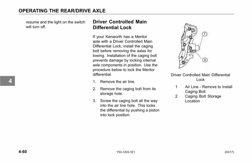
OPERATING THE REAR/DRIVE AXLE
resume and the light on the switchwill turn off.
Driver Controlled MainDifferential Lock
If your Kenworth has a Meritoraxle with a Driver Controlled MainDifferential Lock, install the cagingbolt before removing the axles fortowing. Installation of the caging boltprevents damage by locking internalaxle components in position. Use theprocedure below to lock the Meritordifferential.
1. Remove the air line.
2. Remove the caging bolt from itsstorage hole.
3. Screw the caging bolt all the wayinto the air line hole. This locksthe differential by pushing a pistoninto lock position.
Driver Controlled Main DifferentialLock
1 Air Line - Remove to InstallCaging Bolt
2 Caging Bolt StorageLocation
4-60 Y53-1203-1E1 (03/17)
4

OPERATING THE REAR/DRIVE AXLE
Dual Range (Two-Speed)Rear Axle
Your vehicle may be equipped with atwo-speed or dual range axle (option).You can select two rear axle ratios foroperating under heavy loads or roughterrain as well as for over the roadhauling.
The Low Range provides maximumtorque for hauling heavy loads ortraveling over rough terrain. The HighRange is a faster ratio for highwayspeeds and general over the roadconditions. A switch on the accessoryswitch panel controls the Dual RangeRear Axle. You will notice that theswitch has a guard to protect you fromactivating it accidentally. Always parkyour vehicle with the range selector inLOW.
Dual Range Axle Operation
Important tips on operating a DualRange Axle with Interaxle Differential:
1. Shift the axle with the inter-axledifferential in the unlocked positiononly.
2. When you are driving with poortraction, lock the differential. Whenyou have the differential locked,drive with the axle in LOW rangeonly.
3. When you are driving on a surfacewith good traction, keep theinteraxle differential unlocked. Youcan drive with the axle in the LOWor HIGH range.
4. Always UNLOCK the inter-axledifferential before shifting the axlespeed range.
CAUTIONIf you shift the axle range with theinter-axle differential in LOCK, youcould seriously damage the axles.Never shift the axle range with thedifferential locked.
(03/17) Y53-1203-1E1 4-61
4
OPERATING THE REAR/DRIVE AXLE
Starting-Up
1. Unlock the inter-axle differentialbefore starting.
2. Put the Range Selector in theLOW range. Shift the transmissionto start the vehicle moving.
3. When you are driving on roughterrain and secondary roads, orunder a very heavy load, keep theaxle in the LOW range. Shift thetransmission to maintain properroad speed.
WARNING!Never shift the axle when movingdown hill. Engine driveline disen-gagement may occur, eliminatingengine retardation and allowing thewheels to spin faster than the cur-rent speed of the engine. This mayrequire severe braking to slow thevehicle down and can result in an ac-cident. Failure to comply may resultin personal injury, death, equipmentor property damage.
Proper shifting of the axle depends onthe synchronization of engine/drivelineand wheel speed. When you shiftthe axle, the connection between theengine and wheels is momentarilydisengaged while the gearing issynchronized. Normally when the axleis shifted the speed of the engine, axle,and wheels adjust, allowing for propergear engagement.
When going down hill the wheels willnot slow down, but will tend to speedup, which makes gear synchronizationalmost impossible. As a result, theaxle is neither in HIGH nor LOW rangeand all engine/driveline retardation islost. Without engine retardation it ismore difficult to slow the vehicle downand greater stress is put on the brakesystem.
CAUTIONTo avoid damaging your vehicle shiftthe axle at slower travel speeds untilyou are used to driving with a dualrange axle.
4-62 Y53-1203-1E1 (03/17)
4
OPERATING THE REAR/DRIVE AXLE
LOW to HIGH (Cruising)
When you go from rough terrain tohighway driving, shift the axle to theHIGH range following this procedure:
1. Be sure the differential isUNLOCKED.
2. Maintain your vehicle speed(accelerator depressed) and movethe Range Selector lever to HIGH.
3. Keep driving with the acceleratordepressed until you want the axleto shift.
4. To make the axle shift, release theaccelerator until the axle shifts.You are now in the HIGH axlerange for highway speeds. Shiftthe transmission normally to reachyour desired cruising speed.
HIGH to LOW (Rough Terrain)
If you need to downshift the axle formore power or you are driving onrough terrain:
1. Maintain your vehicle speed(accelerator depressed) and movethe Range Selector lever to LOW.
2. Keep driving with the acceleratordepressed until you want the axleto downshift.
3. To make the axle downshift,release and depress theaccelerator quickly to increase theengine RPM. The axle will shift toLOW range.
4. You are now in the LOW axlerange for rough terrain and heavyloads. Shift the transmissionnormally to maintain the desiredspeed.
Auxiliary Axles - Pusher orTag
Adjustable auxiliary axles can addto the productivity of your vehicle. Itis important to recognize that whenadjustable auxiliary axles are notdeployed while the vehicle is carryinga load, excessive loads may be forcedonto other vehicle components (frame,axles, suspension, brakes, steering,tires, etc.). This overload conditionmay reduce the service life of thesevehicle components. Acceptableservice life is maintained throughcareful operation, proper maintenanceand proper adherence to the vehiclesand auxiliary axle manufacturersoperating limits.
If your vehicle is equipped withfactory-installed pusher or tagaxle(s), or you have a third-party (i.e.body-builder) install these axles, it isyour responsibility to ensure that theaxle lift controls or air-dump valve (if
(03/17) Y53-1203-1E1 4-63
4
OPERATING THE REAR/DRIVE AXLE
equipped) are calibrated prior to puttingthe vehicle into service. The reasonfor doing this important calibration is toobtain the proper axle load distributionfor the entire vehicles axles. As withthe entire vehicles axles, the pusheror tag axle load cannot exceed thecertified GAWR and/or the legal loadlimit of the axle assembly and itsrelated components.
There are three types of pusher or tagaxles:
• Liftable/steerable (axle liftcalibration required)
• Liftable/non-steerable (axle liftcalibration required)
• Non-liftable (some suspensionsrequire dump valve calibration)
Functionality of Auxiliary Axlesinstalled by Kenworth
• Any liftable steerable auxiliaryaxles installed by Kenworth willraise when the parking brake isengaged.
• Any liftable steerable auxiliaryaxles installed by Kenworth willraise when the vehicle is placedinto reverse.
• Liftable/non-steerable axles donot raise when parking brake isengaged or if vehicle is in reverse.
WARNING!Do not operate or park the ve-hicle with auxiliary axles in thedown/loaded position when vehicleis unladen, or is being unloaded.Raise or dump air into driver-con-trolled auxiliary axle(s) prior to un-loading vehicle. Failure to do so canresult in loss of vehicle control orrollaway that may result in personalinjury, death, equipment or propertydamage.
4-64 Y53-1203-1E1 (03/17)
4
OPERATING THE REAR/DRIVE AXLE
CAUTIONNever exceed the manufacturersassigned gross axle weight ratings(GAWR) of each axle when the aux-iliary axles are downloaded. Neverexceed the manufacturers creepratings when operating with a loadwhen the auxiliary axles are un-loaded. Refer to your vehicles com-pliance decals located on the LHdoorjamb for the maximum allow-able load for each axle. Exceedingthe specified weight rating of anyaxle can cause equipment damage.
NOTEAxle Creep Ratings are assignedby the axle manufacturer and arebased on axle model and intendedservice of the vehicle. To find outwhat the allowable creep rating isfor your vehicle, contact the nearestauthorized Kenworth Dealer or axlerepresentative.
Axle Creep Rating DefinitionCreep Ratings
Low speed, off-highway (work site)axle loads, which exceed the standardgross axle weight rating (GAWR) of aparticular axle.
Operator's using vehicles equippedwith liftable auxiliary axles mustconsider creep ratings when anyliftable axle is unloaded or in the raisedposition. Liftable auxiliary axles shouldonly be raised (or unloaded) to improvemaneuverability in an off-road use orwhen vehicle is unloaded.
NOTEAxle Creep ratings MUST NOT beexceeded.
Contact your Kenworth Dealer oraxle manufacturer to determine whatthe creep rating is for your particularaxle(s) and configuration. Creep
ratings are generally limited to thefollowing:
• Tandem rear axles only
• Straight trucks only
• Maximum spring mountcenters per axle manufacturersspecifications
• Maximum tire static loaded radius(SLR) per axle manufacturersspecifications
CAUTIONAlways lower the axles as soonas possible after receiving a load.Never exceed 5 miles per hour whendriving with a load with the auxil-iary axle(s) raised/unloaded. Failureto lower the axle(s) can overloadthe frame and remaining axles, andcould cause equipment damage.
(03/17) Y53-1203-1E1 4-65
4

OPERATING THE REAR/DRIVE AXLE
WARNING!Never operate the vehicle with morepressure in the lift axles than is nec-essary to carry the load, as deter-mined by the calibration proceduredescribed. Failure to do so can re-sult in loss of traction and stability atthe steer and/or drive axles and canresult in increased braking distancewhich could cause loss of vehiclecontrol resulting in an accident. Fail-ure to comply may result in personalinjury, death, equipment or propertydamage.
CAUTIONDo not modify the air system and/orcontrol functionality on a factory in-stalled auxiliary axle(s). Modifyingthe factory operation of the pusherand/or tag axle(s) will void your war-ranty, and can cause equipmentdamage.
CAUTIONA change in tire size on either theauxiliary axles or the drive/steeraxles can change the calibrationof the auxiliary axles. If tires areinstalled with a different loaded ra-dius, the calibration procedure mustbe repeated. Failure to do so cancause equipment damage.
Liftable/Steerable orLiftable/Non-Steerable Pusherand/or Tag Axle CalibrationProcedure
Below are some general instructionson how to adjust and calibrate the aircontrol valve for the auxiliary axles toobtain the proper load distribution ofthe axle(s). For additional operatingand maintenance instructions, see thepusher or tag suspension manufacturerliterature in the glove box or contactthem directly.
NOTEThis procedure must be performedprior to placing the vehicle into ser-vice.
Setting the Pressure-to-Load Ratio
To obtain the desired axle loaddistribution, you must correlate thesuspension air gauge pressure to theactual axle load by scaling the axle
4-66 Y53-1203-1E1 (03/17)
4

OPERATING THE REAR/DRIVE AXLE
weight(s) and adjusting the pressureto obtain the desired load. Once thedesired load or load range is achieved,document the pressure-to-load ratio orsetting for future use.
General Calibration Guidelines
These instructions are general innature. For more specific instructions,review the pusher or tag suspensionmanufacturers maintenance manual orcontact the nearest authorized dealer.
NOTEPerform this procedure at or near aweight scale. Procedure can be per-formed while parked on the weightscale if scale is available.
1. Park loaded vehicle on levelsurface with wheels blocked.
2. Release vehicles springbrakes. (Do not release forLiftable/Non-Steerable pusher ortag axles).
3. Lower the pusher/tag axles withthe axle lift control flip valve. (Forsome non-liftable axles, inflate airsuspension).
4. Adjust the amount of load oneach axle by turning the pressureregulator clockwise to increasethe load or counterclockwiseto decrease the load. (Thesuspension manufacturermay publish pre-establishedPressure-to- Load Ratio PressureSettings to assist you in achievingan estimated ground load.)
5. After setting the pressure to obtainthe desired axle load, verify properground loading with the weightscale.
NOTEExceeding local, state or federalweight limits may result in cita-tions. Contact your local commercialweight enforcement office for limitsin your area.
(03/17) Y53-1203-1E1 4-67
4
OPERATING THE REAR/DRIVE AXLE
Operation Guidelines
NOTESteerable-pusher and/or tag axle(s)will raise when the transmission isshifted into reverse or when theparking brakes are applied.
Maximizing Drive Axle Traction
Adjust the pressure regulator controlknob to a lower pressure until desiredtraction is obtained. By reducing airpressure at pusher or tag axle, loadwill be transferred to drive axles. Donot overload drive axles.
Coupling to a Loaded Trailer
Inflate air springs of the auxiliary axlesto the desired pressure after couplingto a loaded trailer while still maintainingproper traction of the drive axles.
4-68 Y53-1203-1E1 (03/17)
4
OPERATING THE REAR/DRIVE AXLE
Unloading Operation
Always deflate air springs of theauxiliary axles before attempting tounload vehicle. This allows maximumtraction of the drive axles to control thevehicle.
Non-liftable (Non-steerable) Axles
Some suspensions require dump valvecalibration.
Example: Neway dead axles do notlift, but the air can be dumped out ofthem to unload them when empty. Airpressure is controlled via an adjustableregulator. These axles need to becalibrated for load.
Contact your authorized KenworthDealer or axle/suspensionmanufacturer for dump valvecalibration procedures.
(03/17) Y53-1203-1E1 4-69
4
OPERATING THE TRANSMISSION
OPERATING THETRANSMISSION
Introduction
Your Kenworth is equipped with either amanual or automatic transmission withspecial features and gearing to meetyour particular needs. It is importantfor you, the driver, to understandhow your particular transmission isoperated. To do this, you have twosources: this Operator's Manualand the transmission manufacturer'sDriver/Operator's Instruction Manual.Because of the wide variety of differenttransmissions installed in Kenworthvehicles, operating procedures foryour particular transmission are notincluded in this manual; therefore,you should read and understand bothmanuals. Read the general guidelinesand instructions that follow and readthe specific instructions contained
in the transmission manufacturer'sDriver/Operator's Instruction Manual.
You will find a shift pattern diagramin the cab. Check to be sure youknow the correct sequence for yourparticular transmission.
Transmission Warm-Up
In cold weather (below 32° F (0°C), you may find shifting sluggishwhen you first start up. Transmissionwarm-up is especially important atthis time, but it is always a goodidea to warm-up your transmissionbefore starting out on the road. Towarm-up the transmission, follow theseprocedures.
To warm-up the transmissionlubricating oil during engine warm-up,with a single transmission (manual andautomatic):
1. Put the transmission in Neutral.
2. Release the clutch pedal (manualonly) and operate the transmissionin neutral for 3 to 5 minutes priorto operating the transmission ineither forward or reverse range.
3. If you have a two-transmissioncombination:
4-70 Y53-1203-1E1 (03/17)
4
OPERATING THE TRANSMISSION
° Put the main transmission ingear.
° Put the auxiliary transmissionin Neutral. This will allowthe transmission countershaftto turn, agitating the oil andwarming it.
Operating ManualTransmissions
The transmission shift pattern for yourvehicle may be located on the driver’ssun visor and shift control knob. Inaddition to understanding the shiftpattern and its location, you shouldread the transmission manufacturer’smanual provided with your vehiclebefore operating the vehicle.
Putting the Vehicle in Motion
After making sure the vehicle's oiland air pressure are correct and allother parts and systems are in properworking condition:
1. Fully depress the clutch pedal(for manual transmission) untilthe clutch brake makes contact.The contact will occur at about 1inch (2.54 cm) or less from thefloorboard.
° The total stroke of the clutchpedal is about 10 inches (25.4cm). The first 1-½ inches(3.81 cm) is free travel. Afterthe free travel comes therelease stroke, which is thepart that fully releases theclutch. The last 1 inch (2.54cm) engages the clutch brake.
° Always start out in a lowgear. Starting in higher gears,even with a light load, will
(03/17) Y53-1203-1E1 4-71
4
OPERATING THE TRANSMISSION
cause a very jumpy start andexcessive wear.
CAUTIONAlways use first gear or a low speedrange to start the vehicle in motion.The use of a higher gear or speedrange forces undue strain on the en-gine, clutch, other transmission com-ponents, and may cause damage.
2. Evaluate the road surfaceconditions and terrain your vehicleis on. Select a gear low enough tolet your vehicle start forward withthe throttle at idle.
3. Push the parking brake valvehandle (Yellow) against the dashpanel to release the brakes.
4. Release the clutch pedal (manualonly), then gradually accelerate topermit smooth starting.
5. Do not allow your vehicleto roll (even a little) in the
opposite direction during clutchengagement. If you need tostart up on an incline, apply yourservice brakes before you releasethe parking brake. Then releaseyour service brakes as you engagethe clutch and apply throttle.
For further instructions onoperating your transmission, seethe transmission manufacturer'sDriver/Operator's Instruction Manual.
If you have a misaligned gear conditionin your vehicle's transmission andcannot start, gradually release theclutch, allowing the drive gear teeth toline up properly. Then the drive gearcan roll enough to allow the teeth toline up properly and complete the shift.
The best engine performance andmaximum economy is obtained if gearsare properly selected. This efficiencyis achieved by always selecting gearswithin optimum engine RPM, which
is where maximum torque and powerare obtained. For further information,see MORE DRIVING TIPS ANDTECHNIQUES on page 4-5.
4-72 Y53-1203-1E1 (03/17)
4
OPERATING THE TRANSMISSION
Shifting Gears in a New Vehicle
Shift carefully in a new vehicle. Thetransmission may be a little stiff atfirst. Avoid gear clashing, by closelyfollowing these procedures.
When you are operating a new vehicleor one that has been exposed to coldweather, you want the transmissionlubricant (fluid) to circulate and coatthe contacting surfaces of the gears.Metal contacting metal in movingparts may seriously damage yourtransmission, do not drive in onegear for long periods of time until thetransmission lubricant has a chance tocoat all contacting surfaces. Carefullyobserve the free travel in the clutchfor the first few hundred miles. As theclutch lining wears and high spots getworn smooth, you will get less freetravel.
Clutch Brake and Travel
The clutch brake is used for stoppingtransmission gears, allowing you toeasily shift into first gear or reversewithout grinding gears. Approximatelythe last one inch of clutch pedal travelactivates the clutch brake.
• To apply the clutch brake (whilethe vehicle is stopped) fullydepress the clutch pedal to thefloorboard to stop the gears. Withthe throttle at idle, select first gearthen release the clutch pedal to letthe vehicle start forward, until theclutch is fully engaged. See themanufacturer's Driver/Operator'sInstruction Manual for furtherdetails.
If the transmission has a butt-toothcondition and you cannot engage agear, gradually release the clutch.Then the drive gear can roll enough toallow the teeth to line up properly andcomplete the shift.
During Normal Driving
If you want to shift directly into any gearother than first or reverse, depress theclutch pedal only far enough to releasethe clutch. Pushing the clutch to thefloor applies the clutch brake and couldcause gear hang-up.
CAUTIONBe careful not to apply the clutchbrake while the vehicle is moving.The purpose of the clutch brake isto stop the transmission so that youcan shift into a starting gear withoutgrinding gears. Applying the clutchbrake when the vehicle is movingcauses a braking effect on the drive-train and shortens the service life ofthe clutch brake.
(03/17) Y53-1203-1E1 4-73
4

OPERATING THE TRANSMISSION
Double Clutching
Whether you are upshifting or downshifting, it is best to double clutch.Double clutching is easier on thetransmission and on the engine,helping your vehicle match enginespeed with driveline speed andachieving clash-free shifts.
To Double Clutch:
1. Push the clutch pedal down todisengage the clutch.
2. Move the gear shift lever toneutral.
3. Release the pedal to engagethe clutch. This lets you controlthe RPM of the mainshaft gears,allowing you to match the RPM ofthe mainshaft gears to those of theoutput shaft.
° Upshifts: let the engine andgears slow down to the RPMrequired for the next gear.
° Downshifts: press accelerator,increase engine and gearspeed to the RPM required inthe lower gear.
4. Now, quickly press the pedal todisengage the clutch and movethe gear shift lever to the next gearspeed position.
5. Release the pedal to engage theclutch.
More Transmission TipsRiding the Clutch
The clutch is not a footrest. Do notdrive with your foot resting on theclutch pedal. It will allow your clutch toslip, causing excessive heat and wear,damage could result.
4-74 Y53-1203-1E1 (03/17)
4
OPERATING THE TRANSMISSION
Release Bearing Wear
When you must idle your engine for anyperiod of time, shift your transmissionto neutral and disengage the clutch(take your foot OFF of the pedal). Thishelps prevent unnecessary wear toyour clutch release bearing, and it isless tiring for you, too.
Clutch Adjustment
Inspect manual clutches according tothe manufacturer's recommendations.Regular maintenance should befollowed to maintain correct clutchadjustment. Have your dealer'sService Department perform anyadjustment necessary.
Tips
• Always use the clutch whenmaking upshifts or downshifts.
• Always select a starting gearthat will provide sufficient gearreduction for the load and terrain.
• Never downshift when the vehicleis moving too fast.
• Never slam or jerk the shift leverto complete gear engagement.
• Never coast with the transmissionin neutral and the clutchdisengaged.
• To provide smooth gearengagements while shifting,use proper coordination betweenshift lever and clutch.
(03/17) Y53-1203-1E1 4-75
4

OPERATING THE TRANSMISSION
Transmission Oil TemperatureGauge
The Transmission TemperatureGauge (option), see Transmission OilTemperature Gauge on page 3-74,indicates the temperature of the oil inthe transmission. Watch this gaugeto know when the transmission isoverheating: if it is, have it checked byan authorized service representative.
Operating AutomaticTransmissions
An automatic transmission makesshifting much easier, of course. Butbecause your truck pulls a heavyload, it is important to use it efficiently.For correct automatic transmissionoperation, see the manufacturer'sDriver/Operator's Instruction Manual.
WARNING!If your vehicle has a Freedomlinetransmission, be aware that it canroll backwards when stopped on ahill or grade, or when starting froma stop on a hill or grade. Failure tocomply may result in personal injury,death, equipment or property dam-age. Observe the following guide-lines:
• On most automatic transmissionsthere is no PARK position, soyou will need to apply the parking
brake before leaving the cab. SeeUsing the Parking Brake on page4-19.
WARNING!Do not leave the cab without apply-ing the parking brake. The truckcould roll and cause an accident. Al-ways apply the parking brake beforeyou leave the cab. Failure to complymay result in personal injury, death,equipment or property damage.
4-76 Y53-1203-1E1 (03/17)
4
OPERATING THE TRANSMISSION
Auxiliary Transmissions
If you have an auxiliary transmissioninstalled on your Kenworth, seethe transmission manufacturer'sDriver/Operator's Instruction Manual tolearn how to operate it correctly.
Steerable Drive Axle
CAUTIONThe customer cannot change axleratios or tires without Kenworth En-gineering approval.
If you have a Steerable Drive Axleinstalled on your Kenworth, refer tothe auxiliary transmission/transfercase manufacturer's Driver/Operator'sInstruction Manual to learn how tooperate correctly.
(03/17) Y53-1203-1E1 4-77
4
SHUT-DOWN
SHUT-DOWN
Introduction
After you have parked in a safe placecheck your vehicle to make sure it willbe ready for the next trip. To makesure your vehicle is ready to go after along stop (such as overnight), pleasefollow the suggestions below. Yourvehicle will be easier to get going whenyou are ready, and it will be safer foreveryone who might be around it.
Please remember, too, that in somestates it is illegal to leave the enginerunning and the vehicle unattended.
Final Stopping Procedures1. Set the parking brake before
leaving the driver's seat.To hold your vehicle while itis parked, DO NOT rely on thefollowing:
° air brakes
° hand control valve for trailerbrakes
° engine compressionAlways use your parkingbrakes!
WARNING!Do not use the trailer hand brakeor service brakes to park and holdan unattended vehicle, use the park-ing brakes. Because service brakeswork with air pressure, these brakescould slowly release. Your vehiclecould roll, causing a serious acci-dent. Always set the parking brakes.Never rely on the service brakes tohold a parked vehicle. Failure tocomply may result in personal injury,death, equipment or property dam-age.
2. If you must park on a steep grade,always block the wheels.
3. Drain water from the air tanks.
4. While the engine and air supplysystem are still warm, drainmoisture from the air tanks. Openthe tank drains just enough todrain the moisture. Do not depletethe entire air supply.
4-78 Y53-1203-1E1 (03/17)
4
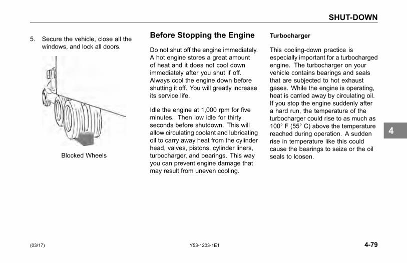
SHUT-DOWN
5. Secure the vehicle, close all thewindows, and lock all doors.
Blocked Wheels
Before Stopping the Engine
Do not shut off the engine immediately.A hot engine stores a great amountof heat and it does not cool downimmediately after you shut if off.Always cool the engine down beforeshutting it off. You will greatly increaseits service life.
Idle the engine at 1,000 rpm for fiveminutes. Then low idle for thirtyseconds before shutdown. This willallow circulating coolant and lubricatingoil to carry away heat from the cylinderhead, valves, pistons, cylinder liners,turbocharger, and bearings. This wayyou can prevent engine damage thatmay result from uneven cooling.
Turbocharger
This cooling-down practice isespecially important for a turbochargedengine. The turbocharger on yourvehicle contains bearings and sealsthat are subjected to hot exhaustgases. While the engine is operating,heat is carried away by circulating oil.If you stop the engine suddenly aftera hard run, the temperature of theturbocharger could rise to as much as100° F (55° C) above the temperaturereached during operation. A suddenrise in temperature like this couldcause the bearings to seize or the oilseals to loosen.
(03/17) Y53-1203-1E1 4-79
4

SHUT-DOWN
Refueling
Air inside the fuel tanks allows waterto condense in the tank. To preventthis condensation while the vehicle isparked for extended periods of time,fill the tanks to 95 percent of capacity.Never fill to more than 95 percentcapacity as this provides room forexpansion resulting from temperatureextremes. When refueling, addapproximately the same amount toeach fuel tank on vehicles with morethan one tank.
WARNING!Do not carry additional fuel contain-ers in your vehicle. Fuel containers,either full or empty, may leak, ex-plode, and cause or feed a fire. Donot carry extra fuel containers, evenempty ones are dangerous. Failureto comply may result in personal in-jury, death, equipment or propertydamage.
WARNING!Do not remove a fuel tank cap nearan open flame. Diesel fuel in thepresence of an ignition source (suchas a cigarette) could cause an ex-plosion. A mixture of gasoline oralcohol with diesel fuel increasesthis risk of explosion. Use only thefuel and/or additives recommendedfor your engine. Failure to complymay result in personal injury, death,equipment or property damage.
Specification: Use only UltraLow Sulfur Diesel (ULSD) Fuel,as recommended by enginemanufacturers. If you need furtherinformation on fuel specifications,consult the Engine Operation andMaintenance Manual.
Location of Fuel Shut-Off Valves
If your vehicle is equipped with shut-offvalves for the take-off and return lines,they are located on the fuel linesentering the top of the fuel tank. Fuelshut-off valves for the fuel crossoverline are on the bottom of the fuel tank,at the crossover line connection.
4-80 Y53-1203-1E1 (03/17)
4
SHUT-DOWN
Sleeper Bunk
If your vehicle has an upper and lowerbunk, the upper bunk can be folded upout of the way to provide you with moredressing area in the sleeper cab. Thelower bunk has storage underneathit to stow your luggage and otherbelongings.
WARNING!Be sure the restraint system isused when anyone is occupying thesleeper while the vehicle is moving.In an accident, an unrestrained per-son lying in a sleeper bunk could beinjured. He or she could be thrownfrom the bunk.
WARNING!Always keep the lower bunk in itsdown (latched) position while the ve-hicle is moving. If left open, storeditems could become loose during anaccident and strike you. Failure tocomply may result in personal injuryor death.
To Lower Upper Bunk: pull on thelanyard in the upper left corner of thebunk to release the bunk. This will freeit from the anchored position and allowyou to lower the bunk.
To Raise Upper Bunk: fold theupper bunk up and push it against theretaining latch until you hear a click.Pull on the bunk to be sure it is latchedsecurely.
WARNING!Be sure the restraint system isused when anyone is occupying thesleeper while the vehicle is moving.In an accident, an unrestrained per-son lying in a sleeper bunk couldbe injured. He or she could bethrown from the bunk. Failure tocomply may result in personal injuryor death.
WARNING!Be sure to stow away all loose be-longings before you move your vehi-cle. And do not store objects on thebunks, they could cause damage orinjury in an accident.
(03/17) Y53-1203-1E1 4-81
4
SHUT-DOWN
WARNING!Be sure the latch that holds the up-per bunk in the folded position isworking properly so the bunk will notfall down. If the bunk falls, you couldbe injured. Failure to complymay re-sult in personal injury or death.
WARNING!Be sure no one ever rides in theupper bunk. That person could bethrown out in an accident and couldbe injured. Do not use the upperbunk while you are moving. Failureto comply may result in personal in-jury or death.
Sleeper Occupant Restraint
The sleeper restraint is stored in acompartment on the rear sleeper cabwall.
WARNING!Failure to properly use the sleeperrestraint when an individual is lo-cated in the sleeper bunk and the ve-hicle is moving can result in injury ordeath.
To Fasten the Sleeper Restraint
1. Locate the tenting straps on eachside of the sleeper restraint andattach them to the buckle-latchplate located on the sides of thesleeper cab (above the lower bunkmattress).
2. Enter the sleeper bunk, and attachthe latch plates (on the forwardedge of the sleeper restraint) to
the buckles on the forward edgeof the bunk.
3. Start with the buckle nearest toyour feet and progress to thebuckle near your head.
4. Adjust the tenting straps to thedesired tension.
NOTEFor partial stowage of the sleeperrestraint the tenting straps may re-main attached and the front bucklesreleased. This allows entrance andexit to and from the sleeper bunk.
5. For complete stowage, disconnectall buckles and replace therestraint into the stowagecompartment. See Sleeper Bunksand Restraints on page 1-29,for more information on cab/seatrestraint systems.
4-82 Y53-1203-1E1 (03/17)
4
MAINTENANCE
PREVENTIVE MAINTENANCEIntroduction . . . . . . . . . . . . . . . . . . 5-7Safety Precautions . . . . . . . . . . . . . . . 5-7Environmental Protection and Material Hazards . . . 5-8
MAINTENANCE SCHEDULE AND LUBRICATIONIntroduction . . . . . . . . . . . . . . . . . 5-10Preventive Maintenance Intervals and Schedule . 5-10Lubrication Specifications . . . . . . . . . . . 5-34Oil Reservoirs . . . . . . . . . . . . . . . . 5-34Lubrication Chart . . . . . . . . . . . . . . . 5-35
AIR SYSTEM MAINTENANCEIntroduction . . . . . . . . . . . . . . . . . 5-38Scheduled Maintenance . . . . . . . . . . . . 5-39Air Tanks . . . . . . . . . . . . . . . . . . 5-40Air Gauges and Air Leaks . . . . . . . . . . . 5-41Air Compressor . . . . . . . . . . . . . . . . 5-43Air Dryer . . . . . . . . . . . . . . . . . . . 5-44
(03/17) Y53-1203-1E1 5-1
5
MAINTENANCE
Air Intake System . . . . . . . . . . . . . . . 5-46Turbocharger . . . . . . . . . . . . . . . . . 5-47Air Cleaners and Filter Replacement . . . . . . 5-48
BRAKE SYSTEM MAINTENANCEIntroduction . . . . . . . . . . . . . . . . . 5-49Checks and Adjustments. . . . . . . . . . . . 5-51Anti-Lock Braking System (ABS) . . . . . . . . 5-54
CAB MAINTENANCEExterior Maintenance . . . . . . . . . . . . . 5-56Cleaning, Protecting and Weather Stripping . . . 5-57Safety Restraint System - Inspection . . . . . . 5-60Windshield Wiper/Washer . . . . . . . . . . . 5-64
COOLING SYSTEM MAINTENANCETopping Up. . . . . . . . . . . . . . . . . . 5-65Adding Coolant . . . . . . . . . . . . . . . . 5-67Change and Refilling . . . . . . . . . . . . . 5-69Radiator Cap . . . . . . . . . . . . . . . . . 5-70
5-2 Y53-1203-1E1 (03/17)
5
MAINTENANCE
Engine (Block) Heater . . . . . . . . . . . . . 5-70
ELECTRICAL MAINTENANCEElectrical System . . . . . . . . . . . . . . . 5-71Fuses, Circuit Breakers, and Relays . . . . . . . 5-71Fuse Inspection and Replacement . . . . . . . 5-72Adding Electrical Options . . . . . . . . . . . 5-73Batteries . . . . . . . . . . . . . . . . . . . 5-78Battery Care . . . . . . . . . . . . . . . . . 5-81Battery Charging . . . . . . . . . . . . . . . 5-81Electrical and Alternator Precautions . . . . . . 5-83Remote Keyless Entry . . . . . . . . . . . . . 5-84Halogen/HID Lamp Headlamp Servicing . . . . . 5-84
ENGINE MAINTENANCEEngine Maintenance . . . . . . . . . . . . . 5-90Engine Lubrication . . . . . . . . . . . . . . 5-91Fuel System . . . . . . . . . . . . . . . . . 5-94Accessory Drive Belts . . . . . . . . . . . . . 5-96Engine Fan . . . . . . . . . . . . . . . . . 5-96
(03/17) Y53-1203-1E1 5-3
5
MAINTENANCE
Engine Mounting . . . . . . . . . . . . . . . 5-97Exhaust System . . . . . . . . . . . . . . . 5-97All Models . . . . . . . . . . . . . . . . . . 5-98Multi-Function Message Display . . . . . . . . 5-98
FRAME MAINTENANCEIntroduction . . . . . . . . . . . . . . . . . 5-99
FRONT AXLE AND SUSPENSION MAINTENANCEAxle Lubrication . . . . . . . . . . . . . . . 5-102Inspection . . . . . . . . . . . . . . . . . . 5-103Wheel Alignment . . . . . . . . . . . . . . . 5-103U-Bolt Torque . . . . . . . . . . . . . . . . 5-103
HEATER AND AIR CONDITIONER MAINTENANCEIntroduction . . . . . . . . . . . . . . . . . 5-105Heater. . . . . . . . . . . . . . . . . . . . 5-106Air Conditioner . . . . . . . . . . . . . . . . 5-107
NOISE AND EMISSION CONTROL MAINTENANCENoise Emission Warranty . . . . . . . . . . . 5-108
5-4 Y53-1203-1E1 (03/17)
5
MAINTENANCE
Inspection and Maintenance Instructions . . . . . 5-110Noise Control System - Maintenance Log . . . . 5-116
REAR AXLE AND SUSPENSION MAINTENANCEGeneral Maintenance . . . . . . . . . . . . . 5-118Visual Inspection . . . . . . . . . . . . . . . 5-119Rear Suspension Fasteners . . . . . . . . . . 5-119Rear Axle Lubrication . . . . . . . . . . . . . 5-121Rear Axle Alignment . . . . . . . . . . . . . 5-121
STEERING AND DRIVELINE MAINTENANCEPower Steering . . . . . . . . . . . . . . . . 5-122Fluid Level and Refill . . . . . . . . . . . . . 5-123Steering Driveline . . . . . . . . . . . . . . . 5-124Driveshaft . . . . . . . . . . . . . . . . . . 5-125
TIRES AND WHEEL MAINTENANCEIntroduction . . . . . . . . . . . . . . . . . 5-126General Safety Requirements . . . . . . . . . 5-126Speed Restricted Tires . . . . . . . . . . . . 5-127
(03/17) Y53-1203-1E1 5-5
5
MAINTENANCE
Tire Inspection and Replacement . . . . . . . . 5-128Tire Inflation and Loading . . . . . . . . . . . 5-128Wheel Mounting and Fastening . . . . . . . . . 5-131Wheel Bearing Adjustment . . . . . . . . . . . 5-133Wheel Replacement with Disc Brake Option . . . 5-134Disc Wheels . . . . . . . . . . . . . . . . . 5-135Comparing Hub Piloted and Ball Seat Parts . . . 5-135Tire Replacement . . . . . . . . . . . . . . . 5-137
TRANSMISSION MAINTENANCEIntroduction . . . . . . . . . . . . . . . . . 5-140
CLUTCHIntroduction . . . . . . . . . . . . . . . . . 5-141Clutch Linkage . . . . . . . . . . . . . . . . 5-141Clutch Adjustment - Normal Wear . . . . . . . . 5-142
5-6 Y53-1203-1E1 (03/17)
5

PREVENTIVE MAINTENANCE
PREVENTIVEMAINTENANCE
Introduction
This section will help you keep yourKenworth in good running condition.There are a number of checks youcan do, and you may be able to dosome of the service work yourself. Butplease, let your Kenworth Dealer doany work you do not have the toolsor skill to perform. Authorized servicemechanics are trained in the propertechnical and safety procedures tomaintain your Kenworth correctly.
Good driving practices, dailyand weekly driver maintenanceinspections, and periodic serviceinspections by an authorized KenworthDealer, will help keep your Kenworth ingood working order and provide manyyears of dependable service.
WARNING!It can be dangerous to attemptmaintenance work without sufficienttraining, service manuals, and theproper tools. You could be injured,or you could make your vehicle un-safe. Do only those tasks you arefully trained and equipped to do.Failure to comply may result in per-sonal injury, death, equipment orproperty damage.
Safety Precautions• Before attempting any
procedures in the enginecompartment, stop the engineand let it cool down. Hotcomponents can burn skin oncontact.
• Be alert and cautious aroundthe engine at all times while theengine is running.
• If work has to be done with theengine running, always (1) setthe parking brake, (2) chockthe wheels, and (3) ensure thatthe shift lever or selector is inNeutral.
• Exercise extreme caution toprevent neckties, jewelry, longhair, or loose clothing fromgetting caught in moving engineparts.
(03/17) Y53-1203-1E1 5-7
5

PREVENTIVE MAINTENANCE
• Disconnect the battery groundstrap whenever you work onthe fuel system or the electricalsystem. When you work aroundfuel, do not smoke or worknear heaters or other firehazards. Keep an approved fireextinguisher handy.
• Always support the vehicle withappropriate safety stands if it isnecessary to work underneaththe vehicle. A jack is notadequate for this purpose.
• When working underneath thevehicle without appropriatesafety stands but with thewheels on the ground (notsupported), make sure that (1)the vehicle is on hard levelground, (2) the parking brakeis applied, (3) all wheels arechocked (front and rear) and (4)the engine cannot be started.Remove the ignition key.
• Never start or let the engine runin an enclosed, unventilatedarea. Exhaust fumes fromthe engine contain carbonmonoxide, a colorless andodorless gas. Carbon monoxidecan be fatal if inhaled.
Incomplete or improper servicingmay cause problems in the operationof the vehicle. If in doubt aboutany servicing, have it done by yourauthorized Kenworth Dealer. Impropermaintenance during the warrantyperiod may also affect the warrantycoverage.
Modifying your vehicle can makeit unsafe. Some modifications canaffect your vehicle's electrical system,stability, or other important functions.Before modifying your vehicle, checkwith your Kenworth Dealer to makesure it can be done safely and correctly.
Environmental Protectionand Material Hazards
Some of the ingredients in engineoil, hydraulic oil, transmission andaxle oil, engine coolant, diesel fuel,air conditioning refrigerant (R12,R-134a and PAG oil), batteries, etc.,may contaminate the environment ifspilled or not disposed of properly.Non-compliance with environmentalregulations can result in fines and/or jailterms. Contact your local governmentagency for information concerningproper disposal.
5-8 Y53-1203-1E1 (03/17)
5
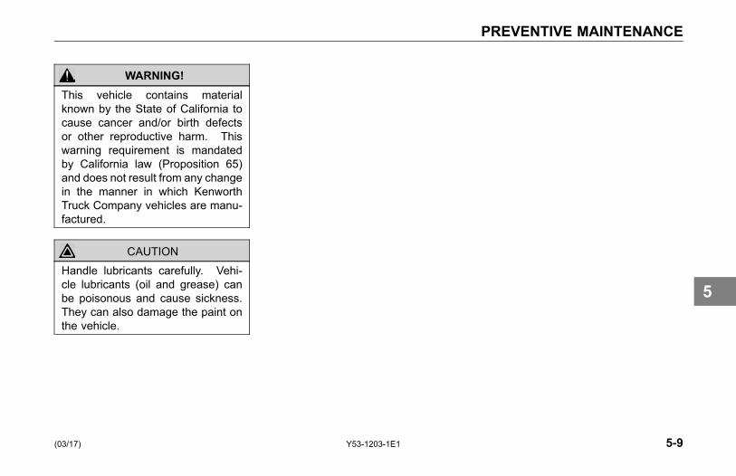
PREVENTIVE MAINTENANCE
WARNING!This vehicle contains materialknown by the State of California tocause cancer and/or birth defectsor other reproductive harm. Thiswarning requirement is mandatedby California law (Proposition 65)and does not result from any changein the manner in which KenworthTruck Company vehicles are manu-factured.
CAUTIONHandle lubricants carefully. Vehi-cle lubricants (oil and grease) canbe poisonous and cause sickness.They can also damage the paint onthe vehicle.
(03/17) Y53-1203-1E1 5-9
5
MAINTENANCE SCHEDULE AND LUBRICATION
MAINTENANCESCHEDULE ANDLUBRICATION
Introduction
The following section summarizespreventivemaintenance and lubricationrequirements for the maintenance ofyour Kenworth. In addition, supportingmanuals and literature are included inthe glove box literature package.
Preventive MaintenanceIntervals and Schedule
Your preventive maintenance programbegins with daily checks you perform.See Driver's Check List on page 1-35.If your Kenworth is serviced regularly,you can avoid many large, expensive,and time-consuming repairs, as wellas ensuring many years of safe andsmooth operation. Also, be advisedthat neglect of recommended servicemay in some cases void your vehicle'swarranty. For your safety and life ofyour vehicle, please follow Table 9,Maintenance Schedule on page 5-16.Remember, there may be maintenanceoperations that demand skills andequipment you do not have. If so,please take your Kenworth to an expertmechanic, for your safety and yourvehicle's performance.
WARNING!It can be dangerous to attempt main-tenance work without sufficient train-ing, service manuals, and the propertools. You could be injured, or youcould make your vehicle unsafe. Doonly those tasks you are fully trainedand equipped to do.
In severe operating conditions suchas earth moving, you will need toperform maintenance checks andservices more frequently. Othersevere operating conditions to beaware of are: where the vehicle isconsistently operated under conditionsof extreme temperature; conditionswhere heavy loads are being hauled;and contaminated environments, orsteep grades. Consult the componentmanufacturer's maintenance manualsfor further information on maintenanceprocedures specific to theseconditions.
5-10 Y53-1203-1E1 (03/17)
5
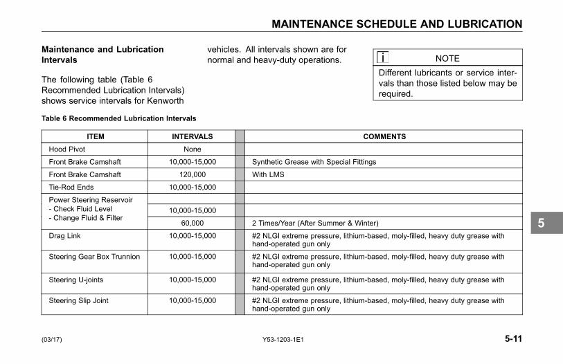
MAINTENANCE SCHEDULE AND LUBRICATION
Maintenance and LubricationIntervals
The following table (Table 6Recommended Lubrication Intervals)shows service intervals for Kenworth
vehicles. All intervals shown are fornormal and heavy-duty operations. NOTE
Different lubricants or service inter-vals than those listed below may berequired.
Table 6 Recommended Lubrication Intervals
ITEM INTERVALS COMMENTSHood Pivot None
Front Brake Camshaft 10,000-15,000 Synthetic Grease with Special Fittings
Front Brake Camshaft 120,000 With LMS
Tie-Rod Ends 10,000-15,000
10,000-15,000Power Steering Reservoir- Check Fluid Level- Change Fluid & Filter
60,000 2 Times/Year (After Summer & Winter)
Drag Link 10,000-15,000 #2 NLGI extreme pressure, lithium-based, moly-filled, heavy duty grease withhand-operated gun only
Steering Gear Box Trunnion 10,000-15,000 #2 NLGI extreme pressure, lithium-based, moly-filled, heavy duty grease withhand-operated gun only
Steering U-joints 10,000-15,000 #2 NLGI extreme pressure, lithium-based, moly-filled, heavy duty grease withhand-operated gun only
Steering Slip Joint 10,000-15,000 #2 NLGI extreme pressure, lithium-based, moly-filled, heavy duty grease withhand-operated gun only
(03/17) Y53-1203-1E1 5-11
5

MAINTENANCE SCHEDULE AND LUBRICATION
ITEM INTERVALS COMMENTSBrake Treadle 10,000-15,000
Clutch Pedal Shaft None
Main and Aux. Transmission- Check Fluid Level- Drain and Refill
Kenworth is Standard with Synthetic Lube (mineral gear lube optional)See manufacturer's operator's manual.
Rear Wheel Bearings -Standard
12 mo./100,000 See www.conmet.com for maintenance details
Rear Wheel Bearings - LMS 12 mo./100,000 -Inspect
3 years/350,000 -Service
Inspect for leaks and check for end-play: 12 mo.\100,000 miles.See hub manufacturer's service manual for details:www.conmet.comIf no oil leaks, then no need for service prior to 3 years/350,000 miles.
Rear Axle- Check Fluid Level- (Rear Axle) Drain, Flush, Refill
Kenworth is Standard with Synthetic Lube (mineral gear lube optional)See manufacturer's operator's manual.
Rear Brake Camshafts 10,000-15,000 Synthetic Grease with Special Fittings
Rear Brake Camshafts 120,000 With LMS
Spring Pins 10,000-15,000 With Rubber Bushed Pins - No Service
Front & Rear Slack Adjusters 10,000-15,000 Synthetic Grease with Special Fittings
King Pins 10,000-15,000
Fifth Wheel 10,000-15,000 40,000 to 60,000 miles for Adjustment
Front Wheel Bearings -Standard
12 mo./100,000 See www.conmet.com for maintenance details
5-12 Y53-1203-1E1 (03/17)
5
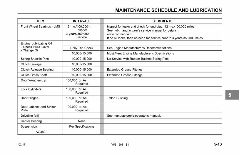
MAINTENANCE SCHEDULE AND LUBRICATION
ITEM INTERVALS COMMENTSFront Wheel Bearings - LMS 12 mo./100,000 -
Inspect3 years/350,000 -
Service
Inspect for leaks and check for end-play: 12 mo.\100,000 miles.See hub manufacturer's service manual for details:www.conmet.comIf no oil leaks, then no need for service prior to 3 years/350,000 miles.
Daily Trip Check See Engine Manufacturer's RecommendationsEngine Lubricating Oil- Check Fluid Level- Change Oil
10,000-15,000 Must Meet Engine Manufacturer's Specifications
Spring Shackle Pins 10,000-15,000 No Service with Rubber Bushed Spring Pins
Clutch Linkage 10,000-15,000
Clutch Release Bearing 10,000-15,000 Extended Grease Fittings
Clutch Cross Shaft 10,000-15,000 Extended Grease Fittings
Door Weatherstrip 100,000 or AsRequired
Lock Cylinders 100,000 or AsRequired
Door Hinges 100,000 or AsRequired
Teflon Bushing
Door Latches and StrikerPlate
100,000 or AsRequired
Driveline (all) See manufacturer's operator's manual.
Center Bearing None
Suspension Per Specifications
AG380
(03/17) Y53-1203-1E1 5-13
5
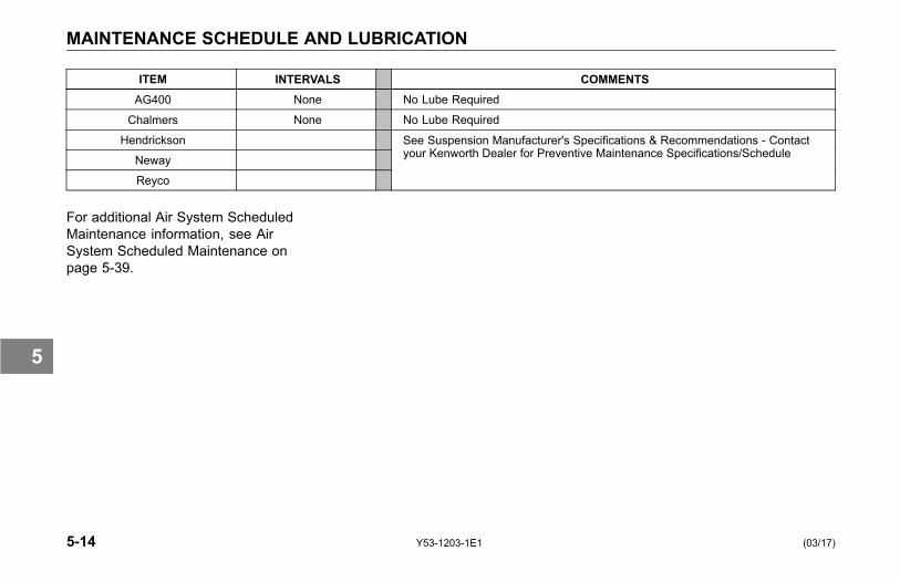
MAINTENANCE SCHEDULE AND LUBRICATION
ITEM INTERVALS COMMENTSAG400 None No Lube Required
Chalmers None No Lube Required
Hendrickson
Neway
Reyco
See Suspension Manufacturer's Specifications & Recommendations - Contactyour Kenworth Dealer for Preventive Maintenance Specifications/Schedule
For additional Air System ScheduledMaintenance information, see AirSystem Scheduled Maintenance onpage 5-39.
5-14 Y53-1203-1E1 (03/17)
5

MAINTENANCE SCHEDULE AND LUBRICATION
Maintenance Schedule
Depending on the service packagebuilt into your Kenworth, use Table9, Maintenance Schedule on page5-16, as a guide to plan servicework for Non-ESI and ESI vehicles.Be sure and follow the frequencyrecommendations for your vehicle.
Maintenance Interval
Perform the listed operation in theshortest interval indicated. Forexample, if there is an "I" for Inspectlisted under 15,000 mi, 60,000 miand 120,000 mi, the shortest intervalindicated is 15,000 mi; therefore, youshould inspect the operation listedevery 15,000 miles. It just so happensthat both 60,000 and 120,000 milesare multiples of 15,000 and the tableindicates that a 15,000 mile intervalwill also occur at 60,000 and 120,000miles.
(03/17) Y53-1203-1E1 5-15
5

MAINTENANCE SCHEDULE AND LUBRICATION
TABLE KEY
A Part of Federal Annual Inspection Every 120,000 Miles (192,000 km)
I Inspect
R Replace
G2 Synthetic Lube Required - 500,000 Drain
Table 9 Maintenance Schedule
INTERVALS COMMENTSOPERATION \ FREQUENCY 7,500
mi(12,000km)
15,000mi
(24,000km)
60,000mi
(96,000km)
120,000 mi(193,000km)
AnnuallyINITIAL DRIVE-IN A B C D
Clutch Brake Operation I I I
Clutch Pedal Free Travel _____ inches I I I
Glass for Cracks or Chips I I I A
Door Window Operation
Interior Lights Replace as Required
Interior Appearance:/Condition: Check for Tears, Stains, Wear
Seats I I I I
Floor Mats I I I I
5-16 Y53-1203-1E1 (03/17)
5

MAINTENANCE SCHEDULE AND LUBRICATION
INTERVALS COMMENTSOPERATION \ FREQUENCY 7,500
mi(12,000km)
15,000mi
(24,000km)
60,000mi
(96,000km)
120,000 mi(193,000km)
AnnuallyDoor Panels I I I I
Headliner I I I I
Dash I I I I
Sleeper I I I I
Covers I I I I
Wiper Operation I I I A
Wiper Blade Condition I I I A
Horns (Electric and Air) I I I A
Mirrors I I I A
SAFETY EQUIPMENT A B C DDrain Water from Air Tanks I I I I Daily
Air Tank Check Valve I I I A
Emergency Operation of Spring Brakes I I I A
Air Press. Build-up time: _______ min. I A
Governed Air Pressure: _______ psi I A
Air Press. Drop-Brakes not Applied: ___ I A
Air Press. Drop-Brakes Applied: ___ I A
(03/17) Y53-1203-1E1 5-17
5

MAINTENANCE SCHEDULE AND LUBRICATION
INTERVALS COMMENTSOPERATION \ FREQUENCY 7,500
mi(12,000km)
15,000mi
(24,000km)
60,000mi
(96,000km)
120,000 mi(193,000km)
AnnuallyFire Extinguisher Charge Replace or Recharge per Extinguisher
Manufacturer Recommendations
Flare Kit/Reflectors A
CIRCLE INSPECTION A B C DPhysical Damage:
Exterior Sheet Metal I I I I
Grille and Radiator I I I I
Trailer Light Cord and Connectors I I I A
Air Lines and Gladhands I I I A
Pintle - Hook/Eye Condition I I I A
5th Wheel Mounting and Condition I I I A
Headlights - High and Low Beams I I I A
Road Lights I I I A
Marker Lights I I I A
Turn Signals I I I A
Emergency Flasher I I I A
Brake Lights I I I A
Backup/Loading Lights I I I A
5-18 Y53-1203-1E1 (03/17)
5

MAINTENANCE SCHEDULE AND LUBRICATION
INTERVALS COMMENTSOPERATION \ FREQUENCY 7,500
mi(12,000km)
15,000mi
(24,000km)
60,000mi
(96,000km)
120,000 mi(193,000km)
AnnuallyLicense Plates: Permits and Mounting I I I A
Mud Flaps/Serviceable I I I A
Fuel Tank Mounting I I I A
Exhaust System-Condition and MountingBolts
I I I A
Frame Fastener Torque: I A See Table Key on page 5-16.
Lubricate:Door Hinges and Latches I I
Body Mounts (Straight Truck Only) I I
Body Sides and Roof Panels(Straight trucks) I I
Cab and Sleeper Air Suspension Mounts I I See Manufacturer's Recommendations
Hood:Hold Down Latches I I Replace if Damaged
Safety Lock I I Replace as Required
Front Pivot Assembly I I
(03/17) Y53-1203-1E1 5-19
5

MAINTENANCE SCHEDULE AND LUBRICATION
INTERVALS COMMENTSOPERATION \ FREQUENCY 7,500
mi(12,000km)
15,000mi
(24,000km)
60,000mi
(96,000km)
120,000 mi(193,000km)
AnnuallyENGINE SERVICE A B C D
Engine Oil - Change
Engine Oil Level
Oil Filters
Fuel Filters
Diesel Particulate Filter (DPF)
Drain Water from Fuel System
Engine Tune-up
Cooling:Check Supplemental Additive/Conditioner to ManufacturerSpecifications_______%
See Engine Manufacturer's OperatorManual provided with this chassis
Coolant Level I I I I
Coolant Protection: _______ degrees I I
Pressure Test I I I Check at Time of Coolant Replacement
Replace Water Filter R New Release at 100-120K - per EngineFilter Manufacturer Recommendations
Hose Condition and Connections I I I
Radiator Mounting I I
5-20 Y53-1203-1E1 (03/17)
5

MAINTENANCE SCHEDULE AND LUBRICATION
INTERVALS COMMENTSOPERATION \ FREQUENCY 7,500
mi(12,000km)
15,000mi
(24,000km)
60,000mi
(96,000km)
120,000 mi(193,000km)
AnnuallyFan Shroud I I
Ring Shroud I I
Fan Assembly and Idler Pulley I I No Service Required on ESI Units
Check Water Pump for Leaks/Play I I
Radiator - Exterior Condition Once every 240,000 Miles (384,000 km)
Replace Engine Coolant For coolant replacement, please seeEngine Operator’s Manual included withthis chassis
Charge Air Cooler Piping (CAC) * Tighten clamps after the first 500 miles(800 km).* See Pipe and Hose Clamp TorqueValues on page 5-94.
Air Cleaner: R Replace Annually/Air Cleaner Restriction:Replace if Greater Than 20
Air Intake Pipe Clamps * Tighten clamps after the first 500 miles(800 km).* See Pipe and Hose Clamp TorqueValues on page 5-94.
Contaminant Accumulation I I Check Every 15,000 Miles (24,000 km)in Dirty Conditions
(03/17) Y53-1203-1E1 5-21
5
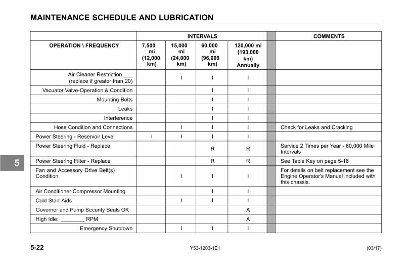
MAINTENANCE SCHEDULE AND LUBRICATION
INTERVALS COMMENTSOPERATION \ FREQUENCY 7,500
mi(12,000km)
15,000mi
(24,000km)
60,000mi
(96,000km)
120,000 mi(193,000km)
AnnuallyAir Cleaner Restriction ___(replace if greater than 20) I I I
Vacuator Valve-Operation & Condition I I
Mounting Bolts I I
Leaks I I
Interference I I
Hose Condition and Connections I I I Check for Leaks and Cracking
Power Steering - Reservoir Level I I I I
Power Steering Fluid - Replace R R Service 2 Times per Year - 60,000 MileIntervals
Power Steering Filter - Replace R R See Table Key on page 5-16
Fan and Accessory Drive Belt(s)Condition I I I
For details on belt replacement see theEngine Operator's Manual included withthis chassis.
Air Conditioner Compressor Mounting I I
Cold Start Aids I I I
Governor and Pump Security Seals OK A
High Idle: ________ RPM A
Emergency Shutdown I I I
5-22 Y53-1203-1E1 (03/17)
5
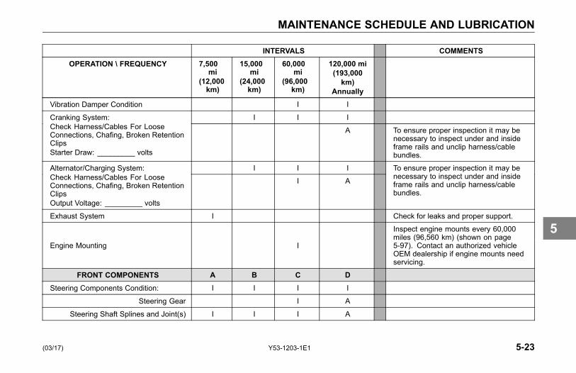
MAINTENANCE SCHEDULE AND LUBRICATION
INTERVALS COMMENTSOPERATION \ FREQUENCY 7,500
mi(12,000km)
15,000mi
(24,000km)
60,000mi
(96,000km)
120,000 mi(193,000km)
AnnuallyVibration Damper Condition I I
I I ICranking System:Check Harness/Cables For LooseConnections, Chafing, Broken RetentionClipsStarter Draw: _________ volts
A To ensure proper inspection it may benecessary to inspect under and insideframe rails and unclip harness/cablebundles.
I I IAlternator/Charging System:Check Harness/Cables For LooseConnections, Chafing, Broken RetentionClipsOutput Voltage: _________ volts
I A
To ensure proper inspection it may benecessary to inspect under and insideframe rails and unclip harness/cablebundles.
Exhaust System I Check for leaks and proper support.
Engine Mounting I
Inspect engine mounts every 60,000miles (96,560 km) (shown on page5-97). Contact an authorized vehicleOEM dealership if engine mounts needservicing.
FRONT COMPONENTS A B C DSteering Components Condition: I I I I
Steering Gear I A
Steering Shaft Splines and Joint(s) I I I A
(03/17) Y53-1203-1E1 5-23
5
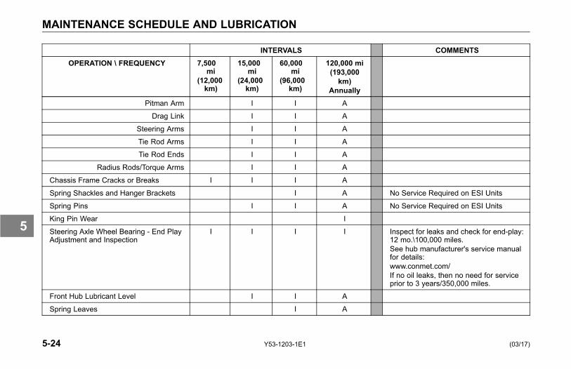
MAINTENANCE SCHEDULE AND LUBRICATION
INTERVALS COMMENTSOPERATION \ FREQUENCY 7,500
mi(12,000km)
15,000mi
(24,000km)
60,000mi
(96,000km)
120,000 mi(193,000km)
AnnuallyPitman Arm I I A
Drag Link I I A
Steering Arms I I A
Tie Rod Arms I I A
Tie Rod Ends I I A
Radius Rods/Torque Arms I I A
Chassis Frame Cracks or Breaks I I I A
Spring Shackles and Hanger Brackets I A No Service Required on ESI Units
Spring Pins I I A No Service Required on ESI Units
King Pin Wear I
Steering Axle Wheel Bearing - End PlayAdjustment and Inspection
I I I I Inspect for leaks and check for end-play:12 mo.\100,000 miles.See hub manufacturer's service manualfor details:www.conmet.com/If no oil leaks, then no need for serviceprior to 3 years/350,000 miles.
Front Hub Lubricant Level I I A
Spring Leaves I A
5-24 Y53-1203-1E1 (03/17)
5
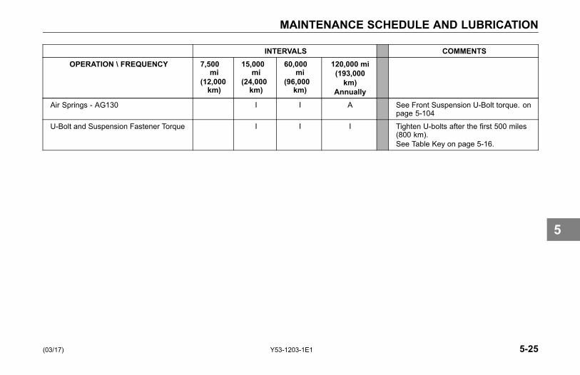
MAINTENANCE SCHEDULE AND LUBRICATION
INTERVALS COMMENTSOPERATION \ FREQUENCY 7,500
mi(12,000km)
15,000mi
(24,000km)
60,000mi
(96,000km)
120,000 mi(193,000km)
AnnuallyAir Springs - AG130 I I A See Front Suspension U-Bolt torque. on
page 5-104
U-Bolt and Suspension Fastener Torque I I I Tighten U-bolts after the first 500 miles(800 km).See Table Key on page 5-16.
(03/17) Y53-1203-1E1 5-25
5

MAINTENANCE SCHEDULE AND LUBRICATION
INTERVALS COMMENTSOPERATION \ FREQUENCY 7,500
mi(12,000km)
15,000mi
(24,000km)
60,000mi
(96,000km)
120,000 mi(193,000km)
AnnuallyREAR COMPONENTS A B C D
Rear Suspension Components -Condition I I I
Track/Torque Rods I I I
Suspension Brackets & Welds - Cracks I I I
Springs, Hangers & Shackles I I I
Walking Beams I I I
Bushings - Worn I I I
Air Springs & Mounts I I I
Lubrication I I I
For Kenworth Non-ProprietarySuspensions, see your KenworthDealer for Preventive MaintenanceSpecifications/Schedule
Suspension Air Fittings - Leaks I I I
U-Bolt and Suspension Fastener Torque
I
For other suspension, "seemanufacturer's recommendations".Rear suspension fasteners: re-torqueafter first 2,000 miles (3,218 km). SeeRear Suspension U-Bolt torque on page5-120.
Leaks:
Coolant I I I I
5-26 Y53-1203-1E1 (03/17)
5
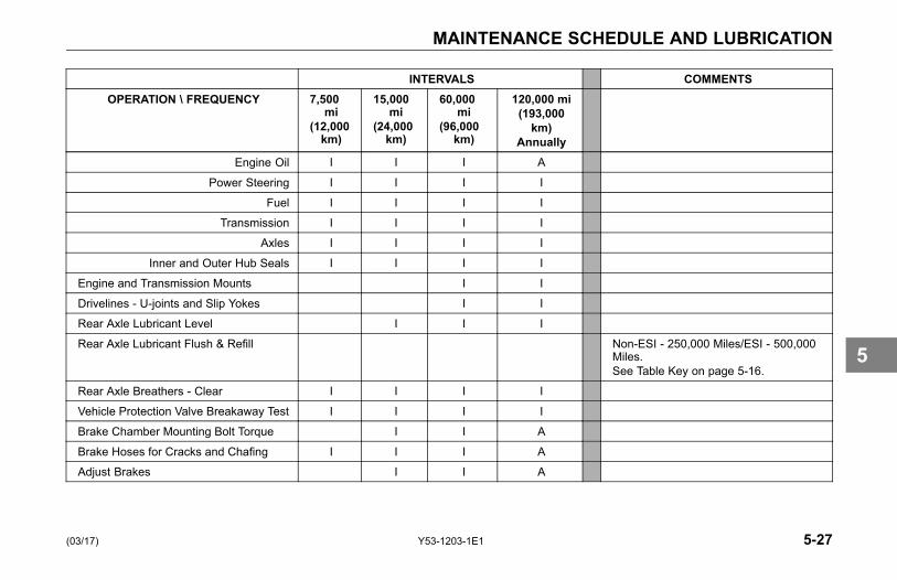
MAINTENANCE SCHEDULE AND LUBRICATION
INTERVALS COMMENTSOPERATION \ FREQUENCY 7,500
mi(12,000km)
15,000mi
(24,000km)
60,000mi
(96,000km)
120,000 mi(193,000km)
AnnuallyEngine Oil I I I A
Power Steering I I I I
Fuel I I I I
Transmission I I I I
Axles I I I I
Inner and Outer Hub Seals I I I I
Engine and Transmission Mounts I I
Drivelines - U-joints and Slip Yokes I I
Rear Axle Lubricant Level I I I
Rear Axle Lubricant Flush & Refill Non-ESI - 250,000 Miles/ESI - 500,000Miles.See Table Key on page 5-16.
Rear Axle Breathers - Clear I I I I
Vehicle Protection Valve Breakaway Test I I I I
Brake Chamber Mounting Bolt Torque I I A
Brake Hoses for Cracks and Chafing I I I A
Adjust Brakes I I A
(03/17) Y53-1203-1E1 5-27
5
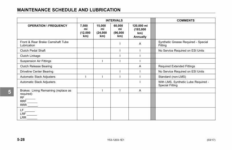
MAINTENANCE SCHEDULE AND LUBRICATION
INTERVALS COMMENTSOPERATION \ FREQUENCY 7,500
mi(12,000km)
15,000mi
(24,000km)
60,000mi
(96,000km)
120,000 mi(193,000km)
AnnuallyFront & Rear Brake Camshaft TubeLubrication I A Synthetic Grease Required - Special
Fitting
Clutch Pedal Shaft I I No Service Required on ESI Units
Clutch Linkage I I
Suspension Air Fittings I I I
Clutch Release Bearing A Required Extended Fittings
Driveline Center Bearing I I No Service Required on ESI Units
Automatic Slack Adjusters I I I I Standard (non-LMS)
Automatic Slack Adjusters I With LMS, Synthetic Lube Required -Special Fitting
I I ABrakes: Lining Remaining (replace asrequired)RF ______RRF ______RRR ______
LF ______LRF ______LRR ______
5-28 Y53-1203-1E1 (03/17)
5
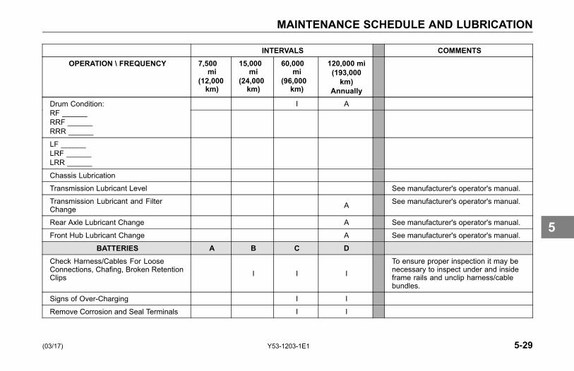
MAINTENANCE SCHEDULE AND LUBRICATION
INTERVALS COMMENTSOPERATION \ FREQUENCY 7,500
mi(12,000km)
15,000mi
(24,000km)
60,000mi
(96,000km)
120,000 mi(193,000km)
AnnuallyI ADrum Condition:
RF ______RRF ______RRR ______
LF ______LRF ______LRR ______
Chassis Lubrication
Transmission Lubricant Level See manufacturer's operator's manual.
Transmission Lubricant and FilterChange A See manufacturer's operator's manual.
Rear Axle Lubricant Change A See manufacturer's operator's manual.
Front Hub Lubricant Change A See manufacturer's operator's manual.
BATTERIES A B C DCheck Harness/Cables For LooseConnections, Chafing, Broken RetentionClips I I I
To ensure proper inspection it may benecessary to inspect under and insideframe rails and unclip harness/cablebundles.
Signs of Over-Charging I I
Remove Corrosion and Seal Terminals I I
(03/17) Y53-1203-1E1 5-29
5
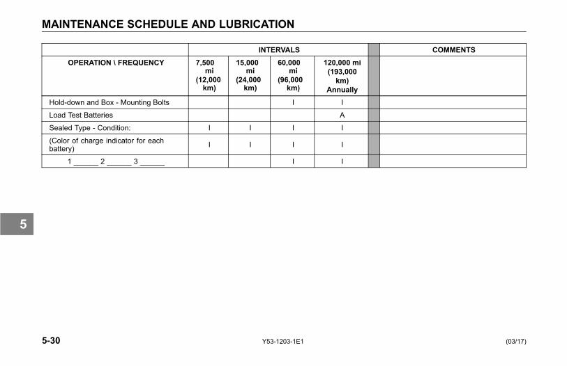
MAINTENANCE SCHEDULE AND LUBRICATION
INTERVALS COMMENTSOPERATION \ FREQUENCY 7,500
mi(12,000km)
15,000mi
(24,000km)
60,000mi
(96,000km)
120,000 mi(193,000km)
AnnuallyHold-down and Box - Mounting Bolts I I
Load Test Batteries A
Sealed Type - Condition: I I I I
(Color of charge indicator for eachbattery) I I I I
1 ______ 2 ______ 3 ______ I I
5-30 Y53-1203-1E1 (03/17)
5

MAINTENANCE SCHEDULE AND LUBRICATION
INTERVALS COMMENTSOPERATION \ FREQUENCY 7,500
mi(12,000km)
15,000mi
(24,000km)
60,000mi
(96,000km)
120,000 mi(193,000km)
AnnuallyTIRES AND WHEELS A B C D
Missing Valve Caps and Stem Locks I I I I
Cracks or Loose Wheel lugs I I I A
Tandem Mating I I I I
Irregular Wear I I I A
Tire Pressure (Record below) I I I I
Remaining Tread (Record below) I I I A
Tires & Wheels Inspection I I I A
Right
Left
(03/17) Y53-1203-1E1 5-31
5

MAINTENANCE SCHEDULE AND LUBRICATION
INTERVALS COMMENTSOPERATION \ FREQUENCY 7,500
mi(12,000km)
15,000mi
(24,000km)
60,000mi
(96,000km)
120,000 mi(193,000km)
AnnuallyAir Pressure Adjusted to:_____________
I I I I
ALIGNMENT A B C DToe-in: ______________ in (mm) I I
Caster: L ________ R ________ I I
Rear Axle Alignment I A
ROAD TEST A B C DSteering/Steering Play I I I I
Shifting I I I
Brakes I I I
Engine Operation (noises, surging, blacksmoke)
I I I
Throttle Linkage I I I I
Engine Brake Operation I I I
Seat Belts I I I
Air Seat Operation I I I
Cab Heater I I I
Air Conditioner I I
5-32 Y53-1203-1E1 (03/17)
5
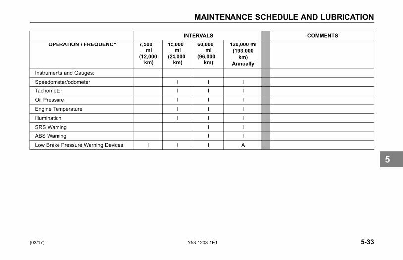
MAINTENANCE SCHEDULE AND LUBRICATION
INTERVALS COMMENTSOPERATION \ FREQUENCY 7,500
mi(12,000km)
15,000mi
(24,000km)
60,000mi
(96,000km)
120,000 mi(193,000km)
AnnuallyInstruments and Gauges:
Speedometer/odometer I I I
Tachometer I I I
Oil Pressure I I I
Engine Temperature I I I
Illumination I I I
SRS Warning I I
ABS Warning I I
Low Brake Pressure Warning Devices I I I A
(03/17) Y53-1203-1E1 5-33
5
MAINTENANCE SCHEDULE AND LUBRICATION
Lubrication Specifications
You will find a complete EngineLubrication Service Guide in the EngineOperation and Maintenance Manual.There, the engine manufacturerexplains more fully all the maintenanceoperations you and a qualified servicemechanic will need. And pleaseremember: one key to keeping yourKenworth running at top economyand in prolonging its life is properlubrication servicing. Neglecting thisessential aspect of vehicle care cancost time and money in the long run.
Below you will find basic informationneeded to perform routine vehiclelubrication. Of course you will wantto schedule service more frequentlyif operating in severe conditionssuch as extreme heat or cold, withvery heavy loads, off-road, etc. Forany special service requirements,consult your service manuals and yourlubricant supplier. The component
manufacturer's specification andrequirements take precedence overother specifications.
CAUTIONHandle lubricants carefully. Vehi-cle lubricants (oil and grease) canbe poisonous and cause sickness.They can also damage the paint onthe vehicle.
CAUTIONDo not mix different types of lubri-cants. Mixing lubricants (oil andgrease) of different brands or typescould damage vehicle components;therefore, drain (or remove) old lu-bricants from the unit before refillingit.
Oil Reservoirs
For oil reservoirs with side filler plugs(transmissions, axles, steering gearboxes, transfer cases, etc.), the oilmust be level with the filler opening.
NOTEUse care when checking the oil levelwith a finger. Just because you canreach the oil level with a finger, doesnot mean the oil level is correct.
NOTEFactory oil level may be above thislevel because it is measured as avolume and not as a specific oil level.This is acceptable to the axle man-ufacturers; however, refill should beper the Proper Oil Level as shown inthe figure below.
5-34 Y53-1203-1E1 (03/17)
5
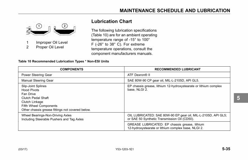
MAINTENANCE SCHEDULE AND LUBRICATION
1 Improper Oil Level2 Proper Oil Level
Lubrication Chart
The following lubrication specifications(Table 10) are for an ambient operatingtemperature range of -15° to 100°F (-26° to 38° C). For extremetemperature operations, consult thecomponent manufacturers manuals.
Table 10 Recommended Lubrication Types * Non-ESI Units
COMPONENTS RECOMMENDED LUBRICANTPower Steering Gear ATF Dexron® II
Manual Steering Gear SAE 80W-90 CP gear oil, MIL-L-2105D, API GL5.
Slip-Joint SplinesHood PivotsFan DriveClutch Pedal ShaftClutch LinkageFifth Wheel ComponentsOther chassis grease fittings not covered below.
EP chassis grease, lithium 12-hydroxystearate or lithium complexbase, NLGI 2.
OIL LUBRICATED: SAE 80W-90 EP gear oil, MIL-L-2105D, API GL5;or SAE 50 Synthetic Transmission Oil (CD50).
Wheel Bearings-Non-Driving AxlesIncluding Steerable Pushers and Tag Axles
GREASE LUBRICATED: EP chassis grease, lithium12-hydroxystearate or lithium complex base, NLGI 2.
(03/17) Y53-1203-1E1 5-35
5
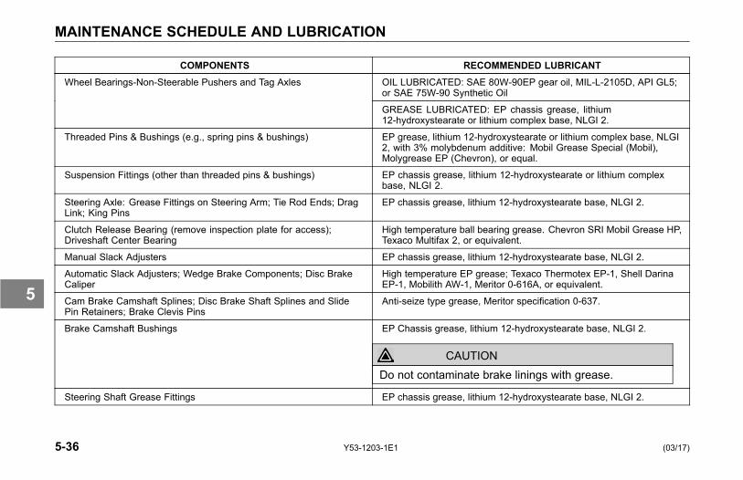
MAINTENANCE SCHEDULE AND LUBRICATION
COMPONENTS RECOMMENDED LUBRICANTOIL LUBRICATED: SAE 80W-90EP gear oil, MIL-L-2105D, API GL5;or SAE 75W-90 Synthetic Oil
Wheel Bearings-Non-Steerable Pushers and Tag Axles
GREASE LUBRICATED: EP chassis grease, lithium12-hydroxystearate or lithium complex base, NLGI 2.
Threaded Pins & Bushings (e.g., spring pins & bushings) EP grease, lithium 12-hydroxystearate or lithium complex base, NLGI2, with 3% molybdenum additive: Mobil Grease Special (Mobil),Molygrease EP (Chevron), or equal.
Suspension Fittings (other than threaded pins & bushings) EP chassis grease, lithium 12-hydroxystearate or lithium complexbase, NLGI 2.
Steering Axle: Grease Fittings on Steering Arm; Tie Rod Ends; DragLink; King Pins
EP chassis grease, lithium 12-hydroxystearate base, NLGI 2.
Clutch Release Bearing (remove inspection plate for access);Driveshaft Center Bearing
High temperature ball bearing grease. Chevron SRI Mobil Grease HP,Texaco Multifax 2, or equivalent.
Manual Slack Adjusters EP chassis grease, lithium 12-hydroxystearate base, NLGI 2.
Automatic Slack Adjusters; Wedge Brake Components; Disc BrakeCaliper
High temperature EP grease; Texaco Thermotex EP-1, Shell DarinaEP-1, Mobilith AW-1, Meritor 0-616A, or equivalent.
Cam Brake Camshaft Splines; Disc Brake Shaft Splines and SlidePin Retainers; Brake Clevis Pins
Anti-seize type grease, Meritor specification 0-637.
Brake Camshaft Bushings EP Chassis grease, lithium 12-hydroxystearate base, NLGI 2.
CAUTIONDo not contaminate brake linings with grease.
Steering Shaft Grease Fittings EP chassis grease, lithium 12-hydroxystearate base, NLGI 2.
5-36 Y53-1203-1E1 (03/17)
5
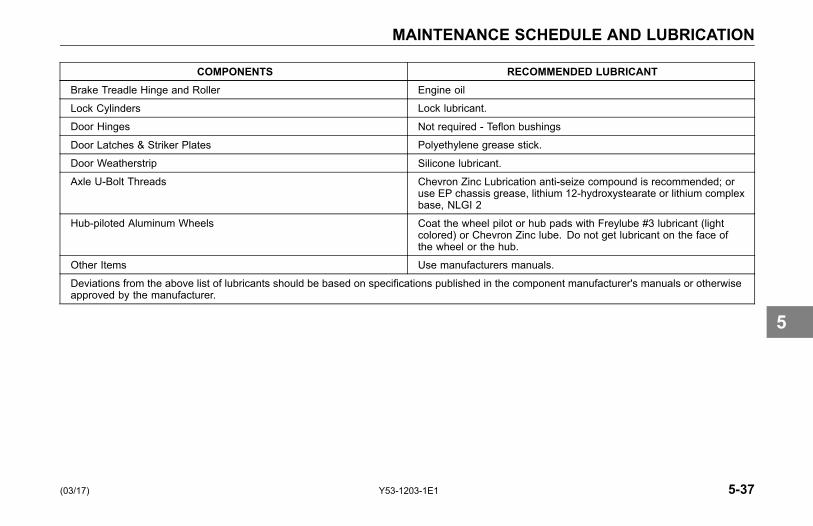
MAINTENANCE SCHEDULE AND LUBRICATION
COMPONENTS RECOMMENDED LUBRICANTBrake Treadle Hinge and Roller Engine oil
Lock Cylinders Lock lubricant.
Door Hinges Not required - Teflon bushings
Door Latches & Striker Plates Polyethylene grease stick.
Door Weatherstrip Silicone lubricant.
Axle U-Bolt Threads Chevron Zinc Lubrication anti-seize compound is recommended; oruse EP chassis grease, lithium 12-hydroxystearate or lithium complexbase, NLGI 2
Hub-piloted Aluminum Wheels Coat the wheel pilot or hub pads with Freylube #3 lubricant (lightcolored) or Chevron Zinc lube. Do not get lubricant on the face ofthe wheel or the hub.
Other Items Use manufacturers manuals.
Deviations from the above list of lubricants should be based on specifications published in the component manufacturer's manuals or otherwiseapproved by the manufacturer.
(03/17) Y53-1203-1E1 5-37
5
AIR SYSTEM MAINTENANCE
AIR SYSTEMMAINTENANCE
Introduction
WARNING!Prior to the removal of any air sys-tem component, always block andhold the vehicle by a secure meansother than the vehicle's own brakes.Depleting air system pressure maycause vehicle to roll unexpectedlyresulting in an accident. Keep handsaway from chamber push rods andslack adjusters, they may apply assystem pressure drops. Failure tocomply may result in personal injury,death, equipment or property dam-age.
• Never connect or disconnecta hose or line containing airpressure. It may whip as airescapes. Never remove acomponent or pipe plug unless
you are certain all systempressure has been depleted.
• Never exceed recommendedair pressure and always wearsafety glasses when workingwith air pressure. Never lookinto air jets or direct them atanyone.
• Never attempt to disassemble acomponent until you have readand understood recommendedprocedures. Some componentscontain powerful springs andinjury or death can result if notproperly disassembled. Useonly proper tools and observeall precautions pertaining to theuse of those tools.
WARNING!Do not release the parking brake orattempt to move the vehicle until airpressure in both circuits is at least100 psi (689 kPa), the level requiredfor normal brake operation. Failureto comply may result in personal in-jury, death, equipment or propertydamage.
• Do not use the trailer hand brakecontrol to hold vehicle whileparked. This control utilizes airpressure for brake application.Because acceptable air leakagelevels cause all truck airsystems to gradually losepressure, vehicle rollawaycould occur, resulting in anaccident, injuries or death.
• Always apply the vehicle andtrailer parking brakes when thevehicle is unattended.
5-38 Y53-1203-1E1 (03/17)
5
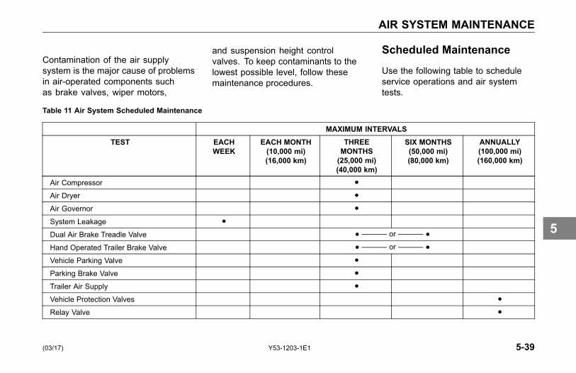
AIR SYSTEM MAINTENANCE
Contamination of the air supplysystem is the major cause of problemsin air-operated components suchas brake valves, wiper motors,
and suspension height controlvalves. To keep contaminants to thelowest possible level, follow thesemaintenance procedures.
Scheduled Maintenance
Use the following table to scheduleservice operations and air systemtests.
Table 11 Air System Scheduled Maintenance
MAXIMUM INTERVALSTEST EACH
WEEKEACH MONTH(10,000 mi)(16,000 km)
THREEMONTHS(25,000 mi)(40,000 km)
SIX MONTHS(50,000 mi)(80,000 km)
ANNUALLY(100,000 mi)(160,000 km)
Air Compressor ●
Air Dryer ●
Air Governor ●
System Leakage ●
Dual Air Brake Treadle Valve ● –––––– or –––––– ●
Hand Operated Trailer Brake Valve ● –––––– or –––––– ●
Vehicle Parking Valve ●
Parking Brake Valve ●
Trailer Air Supply ●
Vehicle Protection Valves ●
Relay Valve ●
(03/17) Y53-1203-1E1 5-39
5
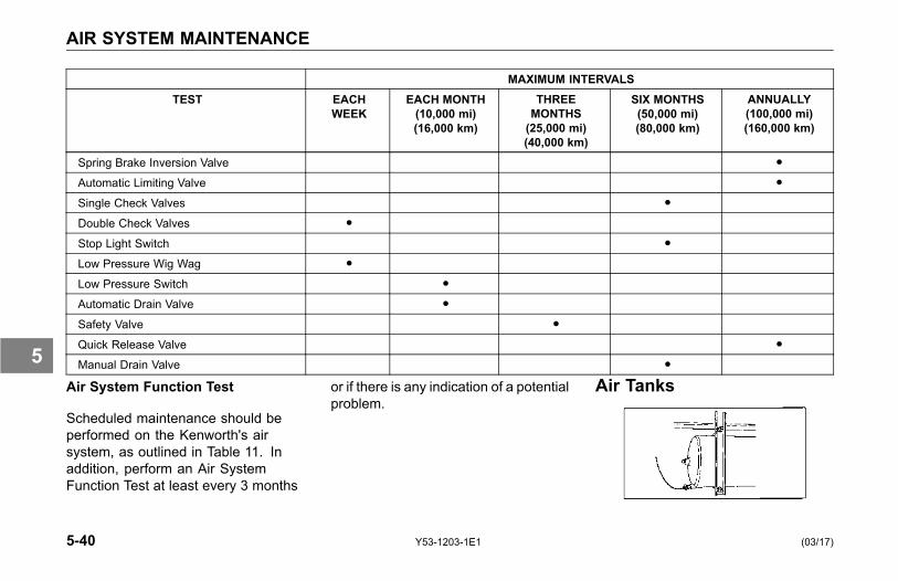
AIR SYSTEM MAINTENANCE
MAXIMUM INTERVALSTEST EACH
WEEKEACH MONTH(10,000 mi)(16,000 km)
THREEMONTHS(25,000 mi)(40,000 km)
SIX MONTHS(50,000 mi)(80,000 km)
ANNUALLY(100,000 mi)(160,000 km)
Spring Brake Inversion Valve ●
Automatic Limiting Valve ●
Single Check Valves ●
Double Check Valves ●
Stop Light Switch ●
Low Pressure Wig Wag ●
Low Pressure Switch ●
Automatic Drain Valve ●
Safety Valve ●
Quick Release Valve ●
Manual Drain Valve ●
Air System Function Test
Scheduled maintenance should beperformed on the Kenworth's airsystem, as outlined in Table 11. Inaddition, perform an Air SystemFunction Test at least every 3 months
or if there is any indication of a potentialproblem.
Air Tanks
5-40 Y53-1203-1E1 (03/17)
5
AIR SYSTEM MAINTENANCE
To eject moisture from the air systemtanks, pull the line which is connectedto the moisture ejection valve.Continue pulling until the air comes outfree of water.
Daily: The supply and service airtanks, must be drained on a dailybasis. Operate air devices daily tocirculate lubricants within the unit.
Periodically: Clean filter screensahead of the valves by removing thescreens and soaking them in solvent.Blow them dry with pressurized airbefore reinstalling them.
WARNING!If the supply and service air tanksare not drained at the recommendedfrequency, water could enter theair lines and valves. This couldcause corrosion or blockage, whichcould compromise the brake systemsafety and potentially cause an ac-cident. Failure to comply may resultin personal injury, death, equipmentor property damage.
CAUTIONDo not use penetrating oil, brakefluid, or wax-based oils in the air sys-tem. These fluids may cause severedamage to air system components.
• Maintain the air compressor toprevent excessive oil bypass.
• Replace worn seals in valves andair motors as they are needed.Your Kenworth Dealer carriesrebuild kits for most units.
Air Gauges and Air Leaks
Your Kenworth comes with twoseparate air pressure gauges fortwo separate systems, Primary andSecondary: the Primary gaugeindicates pressure in the rear brakingsystem; the Secondary gaugeindicates pressure in the front brakingsystem. Each gauge indicates theamount of air pressure in pounds persquare inch (psi).
WARNING!Do not operate the vehicle if leak-age in the air system is detected.Failure to check the brakes or followthese procedures could cause a sys-tem failure, increasing the risk of anaccident and may result in personalinjury, death, equipment or propertydamage.
If the light and alarm do not turn off atstart-up, do not try to drive the vehicleuntil the problem is found and fixed. If
(03/17) Y53-1203-1E1 5-41
5

AIR SYSTEM MAINTENANCE
the pressure in either or both systemsis too low for normal brake operation,i.e., the pointer of one gauge fallsbelow 60 psi (414 kPa), a warning lighton the gauge will glow and the audiblealarm will sound.
Primary Air Pressure Gauge
Secondary Air Pressure Gauge
Follow the procedure below tocheck the compressed air systemfor leaks:
1. Periodically, or after maintenanceor replacement of air systemcomponents:
2. Build up air pressure in the systemto the governor cutout point or until120 psi (827 kPa) is reached.
3. Stop the engine and release theservice brakes.
4. Without applying the brake pedal,observe the rate of air pressuredrop. This rate should not exceed2.0 psi (14 kPa) per minute.
5. Start the engine and build up theair pressure again.
6. Stop the engine, and apply thebrakes fully. Apply the brake pedaland hold it down for five minutes.The pressure drop should not
exceed 3.0 psi (21 kPa) perminute.
7. If you detect excessive leakage(air pressure loss greater than 3.0psi (21 kPa) after five minutes ofbrake application), a leakage testshould be made at the air lineconnections and at all air brakecontrol units. These tests shoulddetermine where air is escaping.
5-42 Y53-1203-1E1 (03/17)
5
AIR SYSTEM MAINTENANCE
Air CompressorOperation
All compressors, regardless of makeor model, run continuously while theengine is running. System pressureis controlled by the governor. Thegovernor acts in conjunction withthe unloading mechanism in thecompressor cylinder block to startand stop compression of air. Thecompressor is unloaded when thesystem pressure reaches 120 psi (827kPa) and compression is reestablishedwhen system pressure falls to 100 psi(689 kPa).
Preventive Maintenance
The following service checks areprovided for your information onlyand should be performed by acertified mechanic. Contact yourKenworth Dealer or the enginemanufacturer's Maintenance Manualfor further information on servicing aircompressors.
After completing any repairs to the airsystem, always test for air leaks, andcheck the brakes for safe operationbefore putting the vehicle in service.
According to Table 11, Air SystemScheduled Maintenance on page 5-39:
• Inspect compressor air filterelement, if so equipped, andreplace element if clogged. Checkcompressor mounting and drivefor alignment and belt tension.Adjust if necessary.
• Remove compressor dischargevalve cap nuts and check forpresence of excessive carbon. Ifexcessive carbon is found, cleanor replace the compressor cylinderhead. Also, check compressordischarge line for carbon, andclean or replace the discharge lineif necessary.
• Disassemble compressor andthoroughly clean and inspectall parts. Repair or replaceall worn or damaged parts, orreplace compressor with a factoryexchange unit.
(03/17) Y53-1203-1E1 5-43
5
AIR SYSTEM MAINTENANCE
CAUTIONWhen draining the engine coolingsystem is required, to prevent dam-age from freezing, the compressormust also be drained at the cylin-der head and block. Engine dam-age could occur if the cooling sys-tem is not periodically drained andmaintained. See Cooling System onpage 5-65 for further information.
Air Dryer
The function of the air dryer is to collectand remove air system contaminants insolid, liquid and vapor form before theyenter the brake system. It providesclean, dry air to the components ofthe brake system, which increasesthe life of the system and reducesmaintenance costs.
NOTEBecause no two vehicles operateunder identical conditions, mainte-nance and maintenance intervalswill vary. Experience is a valuableguide in determining the best main-tenance interval for any one partic-ular operation.
Every 900 operating hours or 25,000miles or every three (3) months checkfor moisture in the air brake systemby opening air tanks, drain cocks, or
valves and checking for presence ofwater.
NOTEA small amount of oil in the systemmay be normal and should not, in it-self, be considered a reason to re-place the desiccant cartridge. Oilstained desiccant can function ade-quately.
A tablespoon of water found in theair tank would point to the need for adesiccant cartridge change. However,the following conditions can alsocause water accumulation and shouldbe considered before replacing thedesiccant cartridge.
• Air usage is exceptionally highand not normal for a highwayvehicle. This may be due toaccessory air demands or someunusual air requirement that
5-44 Y53-1203-1E1 (03/17)
5
AIR SYSTEM MAINTENANCE
does not allow the compressorto load and unload (compressingand non-compressing cycle) in anormal fashion or it may be due toexcessive leaks in the air system.
• In areas where more than a 30°F (17° C) range of temperatureoccurs in one day, small amountsof water can accumulate inthe air brake system due tocondensation. Under theseconditions, the presence of smallamounts of moisture is normaland should not be considered asan indication that the dryer is notperforming properly.
• An outside air source has beenused to charge the air system.This air did not pass through thedrying bed.
Overhaul
Maintenance intervals typical foron-highway operation would be 2 - 3years, 350,000 miles or 10,800 hours.
Maintenance intervals typical for highduty cycle usage such as transit bus,refuse hauler, dump truck, cementmixers and off-highway operationwould be 1 year, 100,000 miles or3,600 hours.
NOTEReview the warranty policy beforeperforming any maintenance proce-dures. An extended warranty maybe voided if unauthorized mainte-nance is performed during this pe-riod.
Bendix AD-IS Series Air Dryer
Your Kenworth vehicle may beequipped with a Bendix AD-IS seriesair dryer. Any air dryer replacementshould be made with an identicalcomponent.
WARNING!If a different air dryer brand or modelis installed on the vehicle other thanwhat was originally installed, it couldcause the air system to not performcorrectly unless the full air systemdesign is reviewed and modifica-tions made to comply with FederalMotor Vehicle Safety Standards(FMVSS 121 - Air Brake Systems)or, in the case of chassis equippedwith the European air system, ECER13. Failure to abide by this warningand maintain compliance to FMVSS121 or ECE R13 could cause lossof vehicle control and may lead topersonal injury or death.
(03/17) Y53-1203-1E1 5-45
5

AIR SYSTEM MAINTENANCE
NOTEThe AD-IS Series air dryer has incor-porated into its design various com-ponents that have typically been in-stalled separately on the vehicle.
See below for components/areasaffected.
• Pressure protection valves
• Safety valve
• Governor and plumbing
• Plumbing of the front and rearservice air tanks
• Plumbing to accessory systems
These components are requiredto meet the Federal Motor VehicleSafety Standards (FMVSS 121 - AirBrake Systems) or, in the case ofchassis equipped with the Europeanair system, ECE R13. As the Warning
above states, any other type of airdryer installed in the place of anAD-IS Series will require changes,modifications, and/or additions toyour vehicle’s air system to maintaincompliance with FMVSS 121 or ECER13. Kenworth strongly recommendsthat if the air dryer is changed from anAD-IS series, you consult your nearestauthorized Kenworth dealer.
Air Intake System
Engine heat, vibration, and agecombine to loosen air intakeconnections and cause cracks inthe tubing and elbows. Leaks in theintake system allow abrasive dust toenter the engine and quickly causeexpensive damage. During your dailywalk-around inspection, carefullycheck all tubing, elbows, clampssupports and fasteners for conditionand tightness.
• Check the Charge-Air-Cooler forair leaks annually. The air leakscan be caused by cracked tubesor header. For service see yourauthorized Kenworth Dealer.
5-46 Y53-1203-1E1 (03/17)
5

AIR SYSTEM MAINTENANCE
CAUTIONDo not use air intake pipes and con-nections as a step or to pull your-self up. This could loosen the con-nections and open the system to un-filtered air which could damage theengine.
Turbocharger
When servicing the air intake andexhaust systems on a turbochargedengine, check the items listed below.
WARNING!Do not operate engine with tur-bocharger intake piping discon-nected. A suction is created whenthe engine is running. This suctioncould draw your hand or anythingelse near it into the impeller fan. Youcould be injured. Always keep theintake piping connected when youwill be running the engine. Failureto comply may result in personalinjury, death, equipment or propertydamage.
Lubricating System: Check the oillines, housing, and connections. Lookfor leaks, damage, or deterioration.Leaks could mean you have damagedoil lines or oil seals.
Manifold: With the engine operating,check for leaking manifold or flangegaskets.
High Frequency Vibration: Vibrationmay indicate turbo rotor imbalance.Have your Kenworth Dealer investigatethis immediately. If you detect anydeficiencies, take the vehicle toan authorized Kenworth Dealer forservicing. Delay could lead to severeand expensive damage to your vehicle.
(03/17) Y53-1203-1E1 5-47
5
AIR SYSTEM MAINTENANCE
Air Cleaners and FilterReplacement
The following service information isbasic to all air cleaner makes andmodels. Service the filter elementsas soon as reasonably possible whenthe Air Cleaner Restriction indicatoror gauge indicates that service isrequired. Have the element servicedat a Kenworth Dealer. Paper elementsrequire care and proper handling,because they are critical to engineservice life.
Service the air cleaner periodically.If the vehicle operates in areas withheavy dust, maintenance should bemore frequent.
5-48 Y53-1203-1E1 (03/17)
5
BRAKE SYSTEM MAINTENANCE
BRAKE SYSTEMMAINTENANCE
Introduction
To operate your vehicle safely, youneed some understanding of its brakesystems. Brake adjustment and brakebalance must be set carefully to allowequal stopping forces at all wheels.Tires are also a very important part ofthe whole system. How fast you canstop depends on how much frictionthere is between the road and yourtires.
All of the following areas areinterrelated and must conform tooriginal specifications:
• tire size
• cam radius
• wedge angle
• drum radius
• brake linings
• brake chambers
• slack adjusters
NOTEThe air brake system of this vehi-cle was configured for ONE of thefollowing operations, TRACTOR orTRUCK, and complies with the re-spective portions of Federal MotorVehicle Safety Standards (FMVSS121 - Air Brake Systems) or, in thecase of chassis equipped with theEuropean air system, ECE R13.A tractor shall not be operated orconfigured as a truck, nor shall atruck be operated or configuredas a tractor without significantmodifications to the air brakesystem in order to retain compli-ance with FMVSS 121 or ECE R13.Contact your Kenworth dealer forinstructions.
Once a brake system is set tospecifications, changing any one ofits components or any combination ofcomponents may cause the system notto work as well. All parts have to worktogether to perform as they should.
Because your brake system is airoperated, see Air System Maintenanceon page 5-38 for more information onchecking your brakes.
Any replacement components inthe brake system should be thesame or better than the originalcomponents. Any changes from theoriginal specifications can affect theperformance of the entire system.
(03/17) Y53-1203-1E1 5-49
5
BRAKE SYSTEM MAINTENANCE
WARNING!Do not use any replacement part inthe brake system unless it conformsexactly to original specifications. Anonconforming part in your vehi-cle's brake system could cause amalfunction resulting in an injuryaccident. Sizes and types are sorelated to one another that a seem-ingly unimportant change in onemay result in a change in how wellthe brakes work for you on the road.If parts do not work together prop-erly, you could lose control of yourvehicle, which could cause a se-rious accident. Failure to complymay result in personal injury, death,equipment or property damage.
WARNING!Do not work on the brake systemwithout the parking brake set andwheels chocked securely. If thevehicle is not secured to preventuncontrolled vehicle movement, itcould roll and may result in personalinjury, death, equipment or propertydamage.
CAUTIONUse wood blocks (4 in. X 4 in. orlarger) against the front and rear sur-faces of the tires. Be sure the vehi-cle cannot move.
Lubrication
Cam-actuated brake componentssuch as anchor pins and brakecamshafts are subjected to hightemperatures, and must be lubricatedwith non-melting, water resistant brakegrease meeting R-S Specification0-616 (NLGI-Grade 1).
• Lubricate according to Table6, Recommended LubricationIntervals on page 5-11.
WARNING!Do not apply too much lubricantto brake components, lubricatesparingly. Excessive amounts oflubricant could contaminate brakelinings, which could reduce brakeeffectiveness and cause an acci-dent. Failure to comply may resultin personal injury, death, equipmentor property damage.
5-50 Y53-1203-1E1 (03/17)
5
BRAKE SYSTEM MAINTENANCE
Brake and Slack AdjusterLubrication
According to the interval, pressurelubricate the slack adjuster and brakecamshaft (bracket/tube). Two greasefittings are provided for both the slackadjuster and camshaft bracket/tube.
• Use standard chassis lubricant(meeting No. 1 grade hightemperature, water proofspecifications).
• Do not use moly-disulfide loadedgrease or oil (they may shorten theservice life of the slack adjuster).
• Do not use pressure-releasegrease fittings when lubricatingthe slack adjuster.
Checks and Adjustments
All vehicle Operator's should check thebrakes regularly. Always adjust thebrakes when they are cool.
• Park the vehicle on a level surfaceand block the wheels beforeattempting any brake checks oradjustments.
Brake Linings
WARNING!Do not use brake linings with a thick-ness below the specified minimum.Such linings will have lining rivetsexposed that can damage the brakedrum and reduce brake efficiency,which could cause an accident orsystem failure. Failure to complymay result in personal injury, death,equipment or property damage.
• Brake linings should be inspectedby a qualified mechanic at anauthorized Kenworth Dealer forwear. See Table 9, MaintenanceSchedule on page 5-16. In severeservice applications inspect thelinings more frequently.
NOTEDepending on your vehicles servicepackage (ESI or Non-ESI), brakeservice requirements will vary.
(03/17) Y53-1203-1E1 5-51
5

BRAKE SYSTEM MAINTENANCE
Automatic Slack Adjusters
Your Kenworth is equipped withautomatic brake (slack) adjusters.
WARNING!Do not work on the brake systemwithout the parking brake set and/orthe wheels chocked securely. If thevehicle is not secured to preventuncontrolled vehicle movement, itcould roll and may result in personalinjury, death, equipment or propertydamage.
CAUTIONUse wood blocks (4 in. X 4 in. orlarger) against the front and rear sur-faces of the tires. Be sure the vehi-cle cannot move.
Periodically, brake adjustmentshould be checked using thefollowing procedure:
1. Check brakes when thetemperature of the servicebrake linings are cool and thesystem air pressure at 100 psi(689 kPa) minimum.
NOTEChock the tires before proceeding.
2. Release the parking brakes toallow the slack adjusters to retract.
3. Measure the retracted pushrodlength from the face of the brakechamber to the center of thepushrod pin.
4. Apply 80 to 90 psi (552 to 621 kPa)brake application and measure thesame distance.
5. The difference is the pushrodtravel distance (applied stroke).
6. Verify that the result is within thecorrect range. See the following
Brake Adjuster Stroke table foracceptable limits.
Measuring Pushrod Travel
1 Short as Possible WithoutBrakes Dragging "AppliedStroke"
2 Released Position3 Applied Position
5-52 Y53-1203-1E1 (03/17)
5
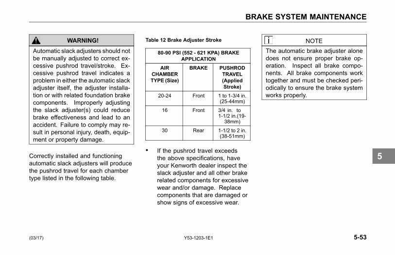
BRAKE SYSTEM MAINTENANCE
WARNING!Automatic slack adjusters should notbe manually adjusted to correct ex-cessive pushrod travel/stroke. Ex-cessive pushrod travel indicates aproblem in either the automatic slackadjuster itself, the adjuster installa-tion or with related foundation brakecomponents. Improperly adjustingthe slack adjuster(s) could reducebrake effectiveness and lead to anaccident. Failure to comply may re-sult in personal injury, death, equip-ment or property damage.
Correctly installed and functioningautomatic slack adjusters will producethe pushrod travel for each chambertype listed in the following table.
Table 12 Brake Adjuster Stroke
80-90 PSI (552 - 621 KPA) BRAKEAPPLICATION
AIRCHAMBERTYPE (Size)
BRAKE PUSHRODTRAVEL(AppliedStroke)
20-24 Front 1 to 1-3/4 in.(25-44mm)
16 Front 3/4 in. to1-1/2 in.(19-
38mm)
30 Rear 1-1/2 to 2 in.(38-51mm)
• If the pushrod travel exceedsthe above specifications, haveyour Kenworth dealer inspect theslack adjuster and all other brakerelated components for excessivewear and/or damage. Replacecomponents that are damaged orshow signs of excessive wear.
NOTEThe automatic brake adjuster alonedoes not ensure proper brake op-eration. Inspect all brake compo-nents. All brake components worktogether and must be checked peri-odically to ensure the brake systemworks properly.
(03/17) Y53-1203-1E1 5-53
5

BRAKE SYSTEM MAINTENANCE
Anti-Lock Braking System(ABS)
Below are some general notes on yourKenworth anti-lock braking system. Allservice work should be performed bya qualified technician at an authorizedKenworth Dealer. The foundationbrake system must be in properworking order to ensure the best ABSperformance.
CAUTIONBefore welding anywhere on thevehicle, detach the ABS ElectronicControl Unit (ECU) connector and allother electronic control units. Fail-ure to comply may result in equip-ment damage.
CAUTIONNever detach the ECU connectorwith the ignition turned on. Failureto comply may result in equipmentdamage.
NOTECheck ABS wiring harnesses andpiping periodically for chafing orother problems. No regular main-tenance is required on the ABScomponents.
NOTEDuring wheel balancing, dyno test-ing, or any time the ignition is onwith part of the ABS disconnected, afailure code will be recorded. Con-sult with your authorized KenworthDealer for information on clearingthe failure code.
If, due to operating conditions, a brakeapplication causes either wheel on thesame axle to begin skidding, wheelspeed sensors immediately signal theanti-lock controller in the modulatorassembly. The controller respondsinstantly by signaling the solenoids inthe modulator which activate the airvalves, reducing application pressureas needed to prevent the wheels fromlocking up. If this over-riding correctionis effective, application pressure isallowed to build up to the original input.
Any malfunction of the anti-locksystem on one or more axles willcause the system to fail-safe, andthe panel-mounted amber warninglight will come on, indicating both amalfunction, and automatic shut-downof the system. If the air system is intact(indicated by the pressure gauges),the service brakes will continue tofunction normally, but without benefitof the anti-lock feature.
5-54 Y53-1203-1E1 (03/17)
5

BRAKE SYSTEM MAINTENANCE
NOTEIf one wheel on any driven axle con-tinues to slip or spin for approxi-mately 4 seconds, this will cause theanti-lock controller for that axle togo into the fail-safe mode, and thewarning light will give a shutdownsignal.
• In this case, the anti-lock systemcan be turned back on, and thewarning light extinguished, byturning the key switch OFF andON, after the vehicle has beenbrought to a full stop. When thekey switch is turned back on, thewarning light will illuminate andremain on for 3 to 5 seconds. Thisis a built-in function test of thewarning light.
WARNING!Do not attempt to recycle theanti-lock system by turning the keyswitch OFF and ON until the vehiclehas been brought to a full stop andthe parking brakes set. Failure to doso could adversely affect steeringand braking control, and may resultin loss of vehicle control and an ac-cident. Failure to comply may resultin personal injury, death, equipmentor property damage.
WARNING!Do not operate the vehicle in theevent of a malfunction in any air cir-cuit. Such a malfunction may pre-vent the brake system from operat-ing properly, and could result in aninjury accident. The vehicle shouldnot be operated until the system isrepaired and both braking circuits,including all pneumatic andmechan-ical components, are working prop-erly. Failure to comply may result inpersonal injury, death, equipment orproperty damage.
(03/17) Y53-1203-1E1 5-55
5
CAB MAINTENANCE
CAB MAINTENANCE
Exterior MaintenancePainted Surfaces
Wash painted surfaces frequently toremove grime and caustic depositswhich may stain the finish. SeeCleaning, Protecting, and WeatherStripping on page 5-57.
Chrome and Aluminum Surfaces
To prevent rust, keep chromed partsclean and protected with wax at alltimes, especially in winter conditionswhere the roads are salted.
• If necessary, use a commercialchrome cleaner to remove lightrust.
• Chrome surfaces are bestcleaned with fresh water. Wipedry to preserve their luster. Acommercial chrome cleaner willremove light rust. After cleaning,wax flat surfaces and apply a thincoat of rust preventive lubricantaround bolts or other fasteners.
• Clean aluminum wheels andbumpers with warm water. Tarremover will get rid of heavydeposits of road grime. To preventspotting, wipe aluminum surfacesdry after washing.
• Under corrosive conditions, suchas driving on salted roads, cleanaluminum parts with steam or highpressure water from a hose. Amild soap solution will help. Rinsethoroughly.
5-56 Y53-1203-1E1 (03/17)
5
CAB MAINTENANCE
Tail Pipe Surface Cleaning
To maintain your quality finish, washwith a soft cloth, mild soap and wateror glass cleaner. A non-abrasivechrome polish can be used sparinglyon hard to clean areas. Do Not cleanyour high heat chrome using scouringpads, abrasive chrome polish, highlyacidic chemical cleaners or any otherabrasive cleaners.
CAUTIONUsing improper cleaning agents canharm your high heat chrome and in-validate your warranty.
Stainless Steel
Even high quality stainless steel partscan rust under prolonged exposureto salt water, especially when thesalt-laden moisture is held againstthe metal surface by road grime. Itis, therefore, important to frequentlyclean salty moisture and grime fromstainless steel surfaces.
• If surface rust is encountered,wash the surface and use acommercial polishing compoundto clean off the rust, followed bya coating of wax (do not applywax to hot parts, such as exhaustpipes).
• Never use steel wool whencleaning stainless steel becauseminute particles of the steel woolcan embed in the surface of thestainless steel and cause ruststaining.
Cleaning, Protecting andWeather Stripping
Frequent washings of the vehicleare required to remove grime andcontaminants that can stain andoxidize paint and accelerate corrosionof plated and polished metal surfaces.
Waxing offers added protection againststaining and oxidation. But to allowenough time for your truck's finish tocure, wait about 30 days after the dateof manufacture before waxing. Do notapply wax in the hot sun and do notfriction burn the paint with a buffingmachine.
Occasionally spray weather-strippingon doors and windows with siliconecompound to help preserve resiliency.This is especially useful in freezingweather to prevent doors and windowsfrom sticking shut with ice.
(03/17) Y53-1203-1E1 5-57
5
CAB MAINTENANCE
Vehicle Cleaning
Precautions
WARNING!Handle cleaning agents carefully.Cleaning agents may be poisonous.Keep them out of the reach of chil-dren.
• Observe all caution labels.
• Always read directions on thecontainer before using anyproduct.
• Do not use any solution that candamage the body paint.
• Most chemical cleaners areconcentrates which requiredilution.
• Only use spot removing fluids inwell ventilated areas.
• Do not use gasoline, kerosene,naphtha, nail polish removeror other volatile cleaning fluids.They may be toxic, flammable orhazardous in other ways.
• Do not clean the underside ofchassis, fenders wheel covers,etc. without protecting your handsand arms. You may cut yourselfon sharp-edged metal parts.
• Moisture, ice, and road salton brakes may affect brakingefficiency. Test the brakescarefully after each vehicle wash.
• Any vehicle is subjected todeterioration from industrialfumes, ice, snow, corrosive roadsalt, etc., to name just a fewcauses. A well-cared-for vehiclecan look like new many yearslater. Regular and correct carewill contribute to maintaining the
beauty and the value of yourvehicle.
Your Kenworth Dealer has a number ofvehicle-care products and can adviseyou on which ones to use for cleaningthe exterior and interior of your vehicle.
CAUTIONDo not aim the water jet directly atdoor locks or latch. Tape the keyholes to prevent water from seepinginto the lock cylinders. Water in lockcylinders should be removed withcompressed air. To prevent locksfrom freezing in the winter, squirtglycerin or lock deicer into the lockcylinders.
5-58 Y53-1203-1E1 (03/17)
5
CAB MAINTENANCE
Washing the Exterior
1. Begin by spraying water over thedry surface to remove all loose dirtbefore applying the car wash andwax solution.Do not wash the vehicle in directsunshine.Do not spray water directly into thecab and sleeper vents.
2. Using soapy water, wash thevehicle with a clean soft cloth ora soft brush made for automotivecleaning.Use cool or warm water and amild, household type soap. Strongindustrial detergents and cleaningagents are not recommended.Do not use stiff brushes, papertowels, steel wool, or abrasivecleaning compounds becausethey will scratch painted, plated,and polished metal surfaces.
3. Rinse surfaces frequently whilewashing to flush away dirt that
might scratch the finishes duringthe washing operation.
4. Wipe everything dry with achamois to avoid water spots.To prevent water spotting, dry offthe cosmetic surfaces with a cleancloth or chamois.
5. Remove road tar with anautomotive type tar remover ormineral spirits.
6. After cleaning and drying, apply aquality automotive wax.
° Do not apply wax in the hotsun.
° Never dust off dry surfaceswith a cloth because it willscratch the finishes.
NOTETo allow enough time for your truck'sfinish to cure, wait at least thirty daysafter the date of manufacture beforewaxing.
(03/17) Y53-1203-1E1 5-59
5
CAB MAINTENANCE
Cleaning the Chassis
• Hose dirt and grime from theentire chassis. Then, if an oilleak develops, you will be able todetect it easier.
• Corrosive materials used for iceand snow removal and dust controlcan collect on the underbody. Ifthese materials are not removed,accelerated corrosion (rust) canoccur on underbody parts such asfuel lines, frames, floor pan, andexhaust system, even though theyhave been provided with corrosionprotection.
At least every spring, flush thesematerials from the under body withplain water. Be sure to clean anyarea where mud and other debris cancollect. Sediment packed in closedareas of the frame should be loosenedbefore being flushed. If desired, yourKenworth Dealer can do this servicefor you.
Cleaning Interior Vinyl andUpholstery
• Wipe vinyl upholstery and liningwith a good commercial upholsterycleaner. Do not use acetone orlacquer thinner.
• Clean fabric upholstery withupholstery shampoo speciallyformulated for this purpose. Followinstructions on the container.
Safety Restraint System -Inspection
The seat belt system, includingwebbing, buckles, latches, andmounting hardware, endures heavyuse in heavy-duty vehicles, much morethan seat belt systems in passengercars. All users should be aware of thefactors contributing to this heavy useand reduced belt life.
WARNING!Failure to properly inspect and main-tain restraint systems can lead to in-jury or loss of life. Without periodicinspection and maintenance to de-tect unsafe conditions, seat restraintcomponents can wear out or not pro-tect you in an accident. Failure tocomply may result in personal injury,death, equipment or property dam-age.
5-60 Y53-1203-1E1 (03/17)
5
CAB MAINTENANCE
Factors contributing to reducedseat belt life:
• High mileage heavy trucks, oftenaccumulate mileage in excess of500,000 total miles (800,000 km)during the vehicle lifetime. Thisis much greater than a typicalpassenger car, which frequentlywill not exceed 125,000 total miles(200,000 km).
• Seat and cab movement intrucks, there is almost constantmovement of the belt due to ridecharacteristics and seat design.The constant movement of the beltinside the restraint hardware andthe potential for the belt to comein contact with the cab and othervehicle parts, contributes to thewear of the entire system.
• Environmental conditions, such asdirt and ultraviolet rays from the
sun, will reduce the life of the seatbelt system.
Due to these factors, the three-pointsafety belt system installed in yourvehicle requires thorough inspectionevery 20,000 miles (32,000 km). Ifthe vehicle is exposed to severeenvironmental or working conditions,more frequent inspections may benecessary.
Any seat belt system that shows cuts,fraying, extreme or unusual wear,significant discoloration due to UV(ultraviolet) exposure, abrasion to theseat belt webbing, or damage to thebuckle, latch plate, retractor hardwareor any other obvious problem shouldbe replaced immediately, regardlessof mileage.
WARNING!It is important to remember that anytime a vehicle is involved in an ac-cident, the entire seat belt systemmust be replaced. Unexposed dam-age caused by the stress of an acci-dent could prevent the system fromfunctioning properly the next time itis needed. Failure to comply may re-sult in personal injury or death.
(03/17) Y53-1203-1E1 5-61
5
CAB MAINTENANCE
Inspection Guidelines
Follow these guidelines wheninspecting for cuts, fraying, extremeor unusual wear of the webbing,and damage to the buckle, retractor,hardware, or other factors. Damage tothese areas indicates that belt systemreplacement is necessary.
WARNING!Replace the entire belt system (re-tractor and buckle side) if replace-ment of any one part is necessary.Unexposed damage to one or morecomponents could prevent the sys-tem from functioning properly thenext time it is needed. Failure tocomply may result in personal injuryor death.
1. Check the web wear in the system.The webbing must be closelyexamined to determine if it iscoming into contact with any sharpor rough surfaces on the seat or
other parts of the cab interior.These areas are typical placeswhere the web will experiencecutting or abrasion. Cuts, fraying,or excessive wear would indicatethe need for replacement of theseat belt system.
2. The pillar web guide (D-loop) isthe area where almost constantmovement of the seat beltwebbing occurs because ofrelative movement between theseat and cab.
3. Check the Comfort Clip for cracksor possible damage and check forproper operation.
4. Check buckle and latch for properoperation and to determine iflatch plate is worn, deformed, ordamaged.
5. Inspect the retractor web storagedevice, which is mounted on thefloor of the vehicle, for damage.The retractor is the heart of the
occupant restraint system and canoften be damaged if abused, evenunintentionally. Check operationto ensure that it is not locked upand that it spools out and retractswebbing properly.
6. If tethers are used, be sure theyare properly attached to theseat and, if adjustable, that theyare adjusted in accordance withinstallation instructions. Tethersmust also be inspected for webwear and proper tightness ofmounting hardware.
7. Mounting hardware should beevaluated for corrosion, and fortightness of bolts and nuts.
8. Check web in areas exposed toultraviolet rays from the sun. If thecolor of the web in these areas isgray to light brown, the physicalstrength of the web may havedeteriorated due to exposure to
5-62 Y53-1203-1E1 (03/17)
5
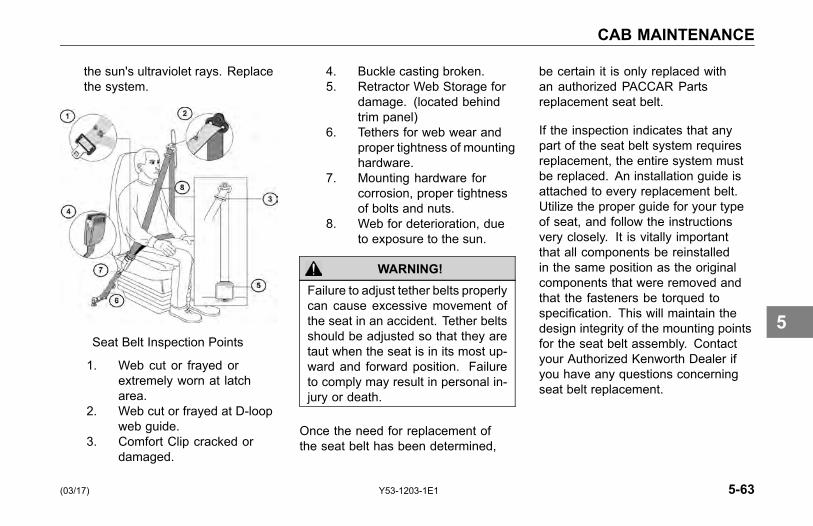
CAB MAINTENANCE
the sun's ultraviolet rays. Replacethe system.
Seat Belt Inspection Points
1. Web cut or frayed orextremely worn at latcharea.
2. Web cut or frayed at D-loopweb guide.
3. Comfort Clip cracked ordamaged.
4. Buckle casting broken.5. Retractor Web Storage for
damage. (located behindtrim panel)
6. Tethers for web wear andproper tightness of mountinghardware.
7. Mounting hardware forcorrosion, proper tightnessof bolts and nuts.
8. Web for deterioration, dueto exposure to the sun.
WARNING!Failure to adjust tether belts properlycan cause excessive movement ofthe seat in an accident. Tether beltsshould be adjusted so that they aretaut when the seat is in its most up-ward and forward position. Failureto comply may result in personal in-jury or death.
Once the need for replacement ofthe seat belt has been determined,
be certain it is only replaced withan authorized PACCAR Partsreplacement seat belt.
If the inspection indicates that anypart of the seat belt system requiresreplacement, the entire system mustbe replaced. An installation guide isattached to every replacement belt.Utilize the proper guide for your typeof seat, and follow the instructionsvery closely. It is vitally importantthat all components be reinstalledin the same position as the originalcomponents that were removed andthat the fasteners be torqued tospecification. This will maintain thedesign integrity of the mounting pointsfor the seat belt assembly. Contactyour Authorized Kenworth Dealer ifyou have any questions concerningseat belt replacement.
(03/17) Y53-1203-1E1 5-63
5

CAB MAINTENANCE
Windshield Wiper/Washer
The windshield wiper system ismaintenance free. Check wiperblades annually or every 60,000 miles(96,000 km). Anco wiper bladesare recommended. See WindshieldWipers/Washer on page 3-119, formore information.
Washer Reservoir
CAUTIONDo not use antifreeze or enginecoolant in the windshield washerreservoir, damage to seals and othercomponents will result.
Daily: Check reservoir water level,located in the engine compartment. Ifnecessary, refill to the proper level.
5-64 Y53-1203-1E1 (03/17)
5
COOLING SYSTEM MAINTENANCE
COOLING SYSTEMMAINTENANCE
WARNING!Do not remove the radiator cap ona hot engine. It can cause scaldingcoolant to spray out and you couldbe burned. If the engine has beenoperated within the last 30 minutes,be very careful in removing the radi-ator cap. Failure to comply may re-sult in personal injury, death, equip-ment or property damage.
WARNING!Do not work on the fan with the en-gine running. The engine fan canengage at any time without warning.Anyone near the fan when it turnson could be injured. Before turningon the ignition be sure that no oneis near the fan. Failure to complymay result in personal injury, death,equipment or property damage.
Kenworth Trucks are standard withAir-to-Air cooling systems. Thesecooling systems incorporate a radiatorto cool engine jacket water, a ChargeAir Cooler to cool turbo-charged engineintake air, and a refrigerant condenserto provide cab air conditioning.
Topping Up
Check the coolant level after eachtrip when the engine has cooled. Thecoolant level should be visible withinthe sight gauge (glass level indicator)on the surge tank. Add coolant asnecessary (see Adding Coolant onpage 5-67).
With the engine cold, top up withpremixed coolant. Add the coolantthrough the pressure cap neck on thesurge tank. The surge tank is locatedon the cooling module mounted on topof the radiator.
With the engine cold, the coolant levelshould be at the full cold coolant level.Use caution not to overfill the systemwith coolant. An overfilled coolingsystem will cause loss of coolantthrough the radiator cap as the coolantexpands during heating. Replacementor make-up coolant should havethe same antifreeze concentration
(03/17) Y53-1203-1E1 5-65
5
COOLING SYSTEM MAINTENANCE
and corrosion inhibitor content asthe original coolant in the coolingsystem. Never add 100% antifreezeto the cooling system. Always diluteantifreeze to the correct concentrationbased on freeze protection prior toadding it to the cooling system. Addingor using 100% antifreeze in a coolingsystem may result in cooling systemplugging and overheating problems.
NOTEIf frequent topping up is necessaryand there are not visible signs ofcoolant leaks when the engine iscold, check for leaks with the engineoperating at normal operating tem-perature.
WARNING!Do not remove the radiator cap ona hot engine. It can cause scaldingcoolant to spray out and you couldbe burned. If the engine has beenoperated within the last 30 minutes,be very careful in removing the radi-ator cap. Failure to comply may re-sult in personal injury, death, equip-ment or property damage.
• Protect face, hands, and armsagainst escaping fluid andsteam by covering the cap witha large, thick rag.
• Carefully and slowly turn cap (onexpansion surge tank) one quarterof a turn to allow excess pressureto escape before completelyremoving cap. If you see anysteam or coolant escaping, donot even try to remove it until theradiator cools down. If you seenothing escaping, still remove the
cap very slowly and carefully. Beready to back off if any steam orcoolant begins to escape.
WARNING!Handle coolant and antifreeze care-fully. Ethylene glycol antifreeze ispoisonous. Store in original fluidcontainer only, and always keepout of reach of children. Failure tocomply may result in personal injury,death, equipment or property dam-age.
WARNING!Never remove the cap on the surgetank while the engine is still hot. Waituntil the coolant temperature is be-low 120º F (50º C). Scalding steamand fluid under pressure may es-cape and cause personal injuries.
5-66 Y53-1203-1E1 (03/17)
5
COOLING SYSTEM MAINTENANCE
WARNING!Do not work on the fan with the en-gine running. The engine fan canengage at any time without warning.Anyone near the fan when it turnson could be injured. Before turningon the ignition, be sure that no oneis near the fan. Failure to complymay result in personal injury, death,equipment or property damage.
Adding Coolant
A mixture of water and low silicateantifreeze should be used forcoolant. Water must be clean andfree of corrosive and scale-formingchemicals. Drinking water may not begood for your vehicle. New vehiclescome premixed with antifreeze andcorrosion inhibitor. Be sure differenttypes of coolant are not mixed. Staywith the same coolant until a completeReplacement is performed.
Coolant Conditioner
A variety of test methods are availablefor measuring coolant conditionerlevels. Test strips provide convenientand consistent results with minimaltraining. Other test methods can beused when appropriate training isprovided. The actual test (i.e. teststrips, etc.) and coolant conditionermaintenance schedule should bedone in accordance with the actualcoolant conditioner manufacturerrecommendations.
The coolant conditioner should berecharged according to Table 6,Recommended Lubrication Intervalson page 5-11, unless otherwisespecified in the Engine ManufacturersMaintenance Manual.
(03/17) Y53-1203-1E1 5-67
5
COOLING SYSTEM MAINTENANCE
Additives
If you add supplemental coolantadditives to the radiator, maintain themat the recommended levels. Readthe label carefully. Too much additivecould harm your vehicle.
Approved additives help neutralizethe water's harmful effects on yourvehicle's cooling system. Ask yourdealer to recommend the best onesfor you.
• Do not add rust inhibitors,radiator sealants, or water pumplubricants containing soluble oil tothe coolant. These additives cancause the anti-corrosion chemicalsnot to work.
• If the cooling system in your truckhas a treated spin-on water filter,install the service filter on all B or Escheduled service intervals. SeeTable 9, Maintenance Scheduleon page 5-16. For more detailed
recommendations check with yourKenworth Dealer or check themanufacturer's Engine Operationand Maintenance Manual.
• Antifreeze solutions containinganti-leak additives will quicklyrestrict the water filter. If thishappens, the filter will not work.So stay away from anti-leakadditives.
CAUTIONDo not add inhibitor if the engine hasa Dry Charge Additive (DCA4) waterfilter cartridge containing corrosioninhibitor, engine damage from overconcentration of silicates may occur.
• The water filter cartridgecontaining DCA4 inhibitor mustbe periodically changed. Referto the Engine Operation andMaintenance Manual for details.
CAUTIONDo not mix inhibitor types. Impropermixing of coolant may damage theengine.
• For coolant conditioner rechargeintervals see the Engine Operationand Maintenance Manual.
5-68 Y53-1203-1E1 (03/17)
5

COOLING SYSTEM MAINTENANCE
Change and Refilling
The coolant must be changedperiodically. When draining coolant,capture old coolant and dispose of itproperly.
Refilling
To refill the cooling system, followthe recommendations below:
1. Before refilling be sure the radiatorand engine block drains areclosed.
2. Move the heater control tomaximum heat position.
3. Remove the surge tank pressurecap.
4. Through the surge tank, fill thesystem with premixed coolant.Pour it in a steady flow until theradiator is full.
5. Start the engine and idle it at lowRPM.
6. Complete the filling as quicklyas possible. Idle the engineuntil it reaches normal operatingtemperature.
7. Fill the radiator as necessaryto raise the coolant level to theproper level.
8. Replace the surge tank pressurecap.
You may find the coolant level is notup to the correct level soon after youhave filled the radiator. This maybe because all the trapped air in thesystem has not yet been purged. Ittakes a little time for all the air to leavethe system after you fill the radiator.
For further details on coolant, coolantcapacities, water filters, and antifreezemixture see the Engine Operation andMaintenance Manual (supplied withthe vehicle).
(03/17) Y53-1203-1E1 5-69
5
COOLING SYSTEM MAINTENANCE
Radiator Cap
CAUTIONWhen replacing the radiator cap al-ways use one with the correct ratedpressure. Failure to do so couldcause engine or cooling systemdamage.
All radiator caps are marked with therated pressure (psi) of the cap.
Engine (Block) Heater
Regularly inspect the engine blockheater wiring and connector fordamaged or frayed wires. Contactyour authorized Kenworth Dealer orthe manufacturer of the heater if youare in need of repairs or information.
WARNING!Do not use the heater if there areany signs of problems. Engine blockheaters can cause fires resulting inpersonal injury, death, equipmentor property damage if not properlymaintained and operated.
CAUTIONAlways unplug the block heater be-fore starting your engine. Damageto the cooling system could occur ifnot turned OFF (unplugged).
Use a solution of half ethylene glycolantifreeze and half water for best
heater performance. Do not usemore than 65 percent concentration ofantifreeze, as a shortened heater lifewill result.
After servicing the cooling system,operate the vehicle for a day or twobefore using the heater. Trappedair inside the engine needs time toescape.
5-70 Y53-1203-1E1 (03/17)
5
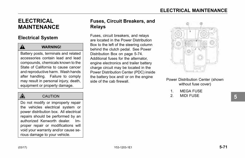
ELECTRICAL MAINTENANCE
ELECTRICALMAINTENANCE
Electrical System
WARNING!Battery posts, terminals and relatedaccessories contain lead and leadcompounds, chemicals known to theState of California to cause cancerand reproductive harm. Wash handsafter handling. Failure to complymay result in personal injury, death,equipment or property damage.
CAUTIONDo not modify or improperly repairthe vehicles electrical system orpower distribution box. All electricalrepairs should be performed by anauthorized Kenworth dealer. Im-proper repair or modifications willvoid your warranty and/or cause se-rious damage to your vehicle.
Fuses, Circuit Breakers, andRelays
Fuses, circuit breakers, and relaysare located in the Power DistributionBox to the left of the steering columnbehind the clutch pedal. See PowerDistribution Box on page 5-74.Additional fuses for the alternator,engine electronics and trailer batterycharge circuit may be located in thePower Distribution Center (PDC) insidethe battery box and/ or on the engineside of the cab firewall. Power Distribution Center (shown
without fuse cover)
1. MEGA FUSE2. MIDI FUSE
(03/17) Y53-1203-1E1 5-71
5

ELECTRICAL MAINTENANCE
Fuse Inspection andReplacement
WARNING!Do not replace a fuse with a fuse of ahigher rating. Doing somay damagethe electrical system and cause afire. Failure to comply may result inpersonal injury, death, equipment orproperty damage.
CAUTIONBefore replacing a fuse, turn OFF alllights and accessories and removethe ignition key to avoid damagingthe electrical system.
CAUTIONNever patch fuses with tin foil orwire. This may cause serious dam-age elsewhere in the electrical cir-cuit, and it may cause a fire.
CAUTIONIf a circuit keeps blowing fuses, havethe electrical system inspected for ashort circuit or overload by an au-thorized Kenworth dealer as soonas possible. Failure to do so couldcause serious damage to the elec-trical system and/or vehicle.
NOTEIf a fuse of the same rating is notavailable, a fuse of a lower ratingmay be temporarily substituted. Youcan also use a fuse from a circuit youcan do temporarily without (for ex-ample an accessory circuit or radio).
See the Kenworth Shop Manual forinstructions on fuse replacement.
All the electrical circuits have fusesto protect them from a short circuit oroverload. If something electrical onyour chassis stops working, the first
thing you should check for is a blownfuse.
1. TurnOFF all lights and accessoriesand remove the ignition key toavoid damaging the electricalsystem.
2. Determine from the chart on thefuse panel which fuse controls thatcomponent.
3. Remove that fuse and see if it isblown.
If a fuse is blown, replace it with a fuseof the same rating.
1 Blown
5-72 Y53-1203-1E1 (03/17)
5
ELECTRICAL MAINTENANCE
Adding Electrical Options
WARNING!Do not add a fuse with a ratinghigher than 30 amps. Follow thecircuit protection size/type recom-mended by the component manu-facturer. Installing a fuse or circuitbreaker greater than designatedmay damage the electrical systemwhich could lead to equipment dam-age and/or personal injury.
CAUTIONFollow all manufacturers' circuit pro-tection recommendations for thecomponents and wires being added.Failure to comply may result inequipment damage.
NOTEIf you are unfamiliar with properelectrical repair practices and pro-cedures, see your authorized Ken-worth dealer for assistance.
NOTEEasy addition of circuits is providedby plug-in connectors that have aground and a power wire.
For proper electrical systemperformance, refer to a wiringdiagram for your chassis before addingelectrical options.
WARNING!Never install a circuit breaker in acircuit that is designated as "fuse-only" circuit(s). Fuse-only circuitsare marked with an * on the reverseside of the Power Distribution Boxcover. Using a circuit breaker inthose fuse-only circuits may causethe circuit to overheat when a shortexists which could lead to equipmentdamage and/or personal injury.
NOTEDo not install a circuit breaker inplace of a fuse for the following cir-cuits:
• ACC FEED
• BODY IGN
• CAB ABS - BATT
• CAB ABS - IGN
(03/17) Y53-1203-1E1 5-73
5
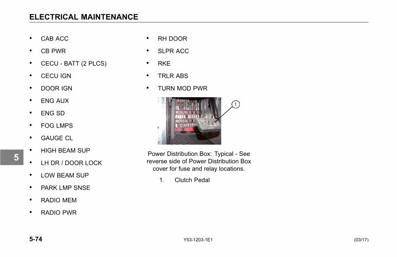
ELECTRICAL MAINTENANCE
• CAB ACC
• CB PWR
• CECU - BATT (2 PLCS)
• CECU IGN
• DOOR IGN
• ENG AUX
• ENG SD
• FOG LMPS
• GAUGE CL
• HIGH BEAM SUP
• LH DR / DOOR LOCK
• LOW BEAM SUP
• PARK LMP SNSE
• RADIO MEM
• RADIO PWR
• RH DOOR
• SLPR ACC
• RKE
• TRLR ABS
• TURN MOD PWR
Power Distribution Box: Typical - Seereverse side of Power Distribution Boxcover for fuse and relay locations.
1. Clutch Pedal
5-74 Y53-1203-1E1 (03/17)
5

ELECTRICAL MAINTENANCE
Power Distribution Box
(03/17) Y53-1203-1E1 5-75
5

ELECTRICAL MAINTENANCE
Chassis Load Center Fuse Box (MX)
5-76 Y53-1203-1E1 (03/17)
5

ELECTRICAL MAINTENANCE
Chassis Load Center Fuse Box (Cummins)
(03/17) Y53-1203-1E1 5-77
5
ELECTRICAL MAINTENANCE
BatteriesBattery Access
The vehicle is originally equipped withthree or four batteries. Replacementbatteries must meet the followingspecifications: maintenance-free,group 31 size, threaded stud, 12V/ 650cold cranking ampere (CCA), and 160minutes of reserve capacity.
The battery compartment is located onthe left side of the vehicle, under thecab access steps.
1. Remove steps by removing 2 boltsfrom each step.
2. Remove 4 bolts and washers fromforward fairing.
3. Remove 2 bolts (A) from step strut.
4. Remove battery cover for access.
In-Cab Battery Box
Your vehicle may be equipped withOptima brand Absorbed Glass Mat(AGM) batteries located in the cabunder the passenger’s seat. The glassmat in AGM batteries is designed toabsorb the battery acid inside thebattery that can leak or spill out inconventional batteries. This designfeature allows Optima batteries to bepositioned in any orientation withoutrisk of leaking.
To access the batteries:
1. Remove 6 fasteners securing thepassenger side seat base to thebattery box assembly.
2. Remove the seat and seat baseas one unit to gain access to thebatteries.
WARNING!Replace only with Optima brandAGM (Group 31) batteries. Use ofother batteries could result in acidleaks causing personal injury in theevent of a vehicle accident. Failureto comply may result in personalinjury, death, equipment or propertydamage.
WARNING!Battery cables and air/electrical har-nesses are mounted to the bottom ofthe floor. Do not drill or screw intofloor pan without first checking thelocation of the cables, harnesses orany other component that might bedamaged. Damaging any compo-nent could result in electrical shockwhich could cause personal injuryand/or loss of a critical truck sys-tem. Failure to comply may result inpersonal injury, death, equipment orproperty damage.
5-78 Y53-1203-1E1 (03/17)
5

ELECTRICAL MAINTENANCE
WARNING!Batteries release gases that areflammable. Batteries are equippedwith vent tubes and flash arrestorswhich vent battery gases out of thecab. Ensure all vent tubes, flash ar-restors and grommets are properlyinstalled and ensure they are clearand functioning properly. Failure toreinstall or keep the vent tubes andgrommets clear or ensure the flasharrestor(s) are functioning properlycould result in personal injury orequipment damage. Failure to com-ply may result in personal injury,death, equipment or property dam-age.
WARNING!Electrical damage or battery ex-plosion can occur when improperlycharging batteries. Refer to theoperation and service manual forappropriate charging instructions.Failure to comply may result in per-sonal injury, death, equipment orproperty damage.
CAUTIONDo not store other items in this bat-tery box. Failure to comply could re-sult in damage to the truck and/orbatteries.
CAUTIONProperly secure battery tie downsand battery box cover when rein-stalling batteries after service. Donot over tighten. Over tighteningcan crack the battery case which canlead to equipment damage.
Replacing Parts Removed forAccess
1. Replace battery cover.
2. Install 2 bolts in step strut. Torqueto 24-32 lb-ft (33-43 Nm).
3. Install fairing and install 4 bolts.Torque to 6-7 lb-ft (8-9 Nm).
4. Install steps by installing 2 bolts ineach step. Torque to 24-32 lb-ft(33-43 Nm).
WARNING!Always reinstall the steps before en-tering the cab. Without the steps youcould slip and fall, resulting in pos-sible injury to yourself. Failure tocomply may result in personal injury,death, equipment or property dam-age.
(03/17) Y53-1203-1E1 5-79
5
ELECTRICAL MAINTENANCE
WARNING!Fairings not installed properly couldcome loose and cause other mo-torists to have an injury accident. Itis important that fairings be installedproperly. Failure to comply may re-sult in personal injury, death, equip-ment or property damage.
WARNING!Before attempting any work on thebatteries or electrical system, re-move all jewelry. If metal jewelry orother metal comes in contact withelectrical circuits, a short circuit mayoccur causing you to be injured, aswell as electrical system failure anddamage.
Removing and Installing Batteries:
1. Be sure all switches on the vehicleare turned OFF.
2. Disconnect negative ground cablefirst.
3. Disconnect positive cable.
4. Unscrew bolt of holding plate withopen end wrench.
NOTEAlways dispose of automotive bat-teries in a safe and responsibleman-ner. Contact your authorized Ken-worth dealer for disposal standards.Call your local authorized recyclingcenter for information on recyclingautomotive batteries.
Follow the procedure below to reinstallbatteries on the vehicle:
NOTEMake sure to reconnect the ground(negative) cable last.
1. Place batteries in vehicle andtighten bolt of holding plate.
2. Reconnect positive cable.
3. Reconnect ground (negative)ground cable.
WARNING!Battery replacement may alter ordisturb battery cable routing. Checkto insure battery cables are freefrom any point of chaffing. Failureto comply may result in personalinjury, death, equipment or propertydamage.
5-80 Y53-1203-1E1 (03/17)
5
ELECTRICAL MAINTENANCE
Battery Care
Regular attention to the chargingsystem will help prolong the servicelife of the batteries. Here are somecommon causes of battery failure:
Overcharge: this condition resultsfrom improper voltage regulatoradjustment. It results in overheatingof the battery, warped plates, andevaporation of electrolyte.
Undercharge: the voltage regulatoris malfunctioning, the drive belt isslipping, or your vehicle has undergonelong periods of standing idle or shortdistance driving. These conditionsresult in battery plates becomingcovered with a hard coating.
Vibration: loose battery hold-downsmay cause battery plate failure.
Short Circuits: these discharge thebattery by draining electricity.
Dirty or Loose Connections:improper connections may stop theflow of electrical power to and from thebattery.
Battery Charging
Except for using small trickle charges(as explained in Slow Battery Chargingon page 5-81) to maintain batterycondition, you should have yourvehicle's batteries charged by aqualified service facility.
WARNING!Batteries can injure you severely.They contain acid, produce poi-sonous and explosive gases, andsupply levels of electric current highenough to cause burns. A sparkor flame near a battery on chargemay cause it to explode with greatforce. Never remove or tamper withthe battery caps. Failure to complymay result in personal injury, death,equipment or property damage.
(03/17) Y53-1203-1E1 5-81
5
ELECTRICAL MAINTENANCE
To help reduce the risk of personalinjuries, follow these guidelinescarefully when recharging a battery:
• Before attempting any servicein the electrical installation,disconnect the battery negativecable.
• Allow no sparks or open flameanywhere near the charging area.
• Charge a battery only in awell-ventilated area, such asoutdoors or in a fully open garagewhich contains no pilot lights orother flames. Gases generatedduring the charging process mustbe allowed to escape.
• Always make sure the batterycharger is OFF before connectingor disconnecting the cable clamps.
• To avoid short circuits, damageto the vehicle, or personal injury,never place metal tools or jumper
cables on the battery or nearby.Metal that accidentally comes incontact with the positive batteryterminal or any other metal on thevehicle (that is in contact with thepositive terminal), could cause ashort circuit or an explosion.
Charging Reminders
• Use protective eyewear.
• Keep all batteries away fromchildren.
• Never reverse battery poles.
• Never attempt to place the vehiclein motion, or run the engine withbatteries disconnected.
• Keep the battery clean and dry.
• Look for any signs of damage.
• Battery terminals should notbe coated with impropergrease. Use petroleum jellyor commercially available,noncorrosive, nonconductiveterminal coatings.
• Never use a fast charger as abooster to start the engine. Thiscan seriously damage sensitiveelectronic components such
5-82 Y53-1203-1E1 (03/17)
5
ELECTRICAL MAINTENANCE
as relays, radio, etc., as wellas the battery charger. Fastcharging a battery is dangerousand should only be attempted bya competent mechanic with theproper equipment.
Slow Battery Charging
NOTEFollow the instructions that comewith your battery charger.
• It is not necessary to remove thebattery from the compartment.
WARNING!Charger cables must be connectedpositive to positive (+ to +) and neg-ative to negative (- to -). If con-nected improperly, batteries couldexplode. Failure to comply may re-sult in personal injury, death, equip-ment or property damage.
• Always make sure thebattery charger is OFF beforeconnecting or disconnectingthe cable clamps. To reducethe danger of explosions andresulting personal injury, do notconnect or disconnect chargercables while the charger isoperating.
1. Disconnect the battery cables.
2. Connect charger cables.
3. Start charging the battery at a ratenot over 6 amperes. Normally, abattery should be charged at nomore than 10 percent of its ratedcapacity.
4. After charging, turn OFF chargerand disconnect charger cables.
Electrical and AlternatorPrecautions
Take the following precautions toavoid burning out alternator diodes:
• Do not start the enginewith alternator disconnected(connections removed) from thecircuit.
• Before welding, disconnect allelectronic connections to thevehicle batteries.
• Remove battery power cable andinsulate it from the vehicle.
• Do not run the engine with thebatteries disconnected.
• Do not disconnect the batterycables or alternator connectioncables with the engine running.
• Never turn the ignition switch fromthe ON position to the STARTposition with the engine running.
(03/17) Y53-1203-1E1 5-83
5
ELECTRICAL MAINTENANCE
• When charging the battery(installed in the vehicle) disconnectthe battery cables.
• Do not reverse the cables of thealternator, starter motor, or battery.
• Do not polarize the alternator. Thealternator should not be polarizedlike a generator. To ensure correctpolarity, use a test lamp or avoltmeter.
Remote Keyless EntryTroubleshooting
The remote keyless entry system maybecome non-operational due to failureof a key fob battery. If you have issueswith a key fob, replace the battery andre-synchronize the key fob. In somesituations, the key fob may need tobe replaced and in others, a fuse mayhave failed and may render both keyfobs inoperative.
See battery replacement instructionson page 1-15.
See synchronization instructions onpage 1-16.
Contact your dealer for more help, ifa key fob does not work and it is notbecause of a bad battery.
Halogen/HID LampHeadlamp Servicing
A Halogen or HID (High IntensityDischarge) Projector headlampassembly comprises of a Halogenor HID projector low beam, acomplex reflector high beam, two sidemarker/turn signal lamps, housing andmounting/wiring hardware.
NOTEIt is normal for some fogging on theinside of the lens to occur. Thiscondensation may be removed bydriving the vehicle for an extendedperiod with the headlights turnedon. Servicing is required if waterdroplets or puddles of water form onthe inside of the headlamp.
5-84 Y53-1203-1E1 (03/17)
5

ELECTRICAL MAINTENANCE
Servicing
Access is gained from the rear of theassembly.
Rear Of Halogen/HID Housing
1 Low-beam Access Cover
Follow the procedure below to replaceHID bulbs.
Removing Ignition Device
1. Rotate low-beam access covercounter-clockwise and removecover.
Low-Beam Access Cover
2. Rotate Ignition Device 25°counter-clockwise.
° High-voltage line will beautomatically ejected as asafety precaution.
Ignition Device
1 High-voltage cableejected
2 Ignition Device
3. Pull Ignition Device away frombulb.
Remove HID Bulb
1. Squeeze the two projector housingspring ends marked with arrowstowards each other and thendeflect away from bulb housing.
(03/17) Y53-1203-1E1 5-85
5
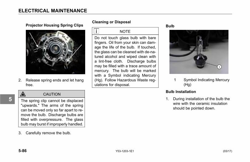
ELECTRICAL MAINTENANCE
Projector Housing Spring Clips
2. Release spring ends and let hangfree.
CAUTIONThe spring clip cannot be displaced"upwards." The arms of the springcan be moved only so far apart to re-move the bulb. Discharge bulbs arefilled with overpressure. The glassbulb may burst if improperly handled.
3. Carefully remove the bulb.
Cleaning or Disposal
NOTEDo not touch glass bulb with barefingers. Oil from your skin can dam-age the life of the bulb. If touched,the glass can be cleaned with de-na-tured alcohol and wiped clean witha lint-free cloth. Discharge bulbsmay be filled with a trace amount ofmercury. The bulb will be markedwith a Symbol indicating Mercury(Hg). Follow Hazardous Waste reg-ulations for disposal.
Bulb
1 Symbol Indicating Mercury(Hg)
Bulb Installation
1. During installation of the bulb thewire with the ceramic insulationshould be pointed down.
5-86 Y53-1203-1E1 (03/17)
5
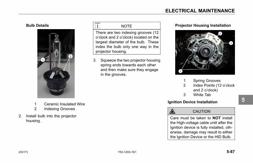
ELECTRICAL MAINTENANCE
Bulb Details
1 Ceramic Insulated Wire2 Indexing Grooves
2. Install bulb into the projectorhousing.
NOTEThere are two indexing grooves (12o’clock and 2 o’clock) located on thelargest diameter of the bulb. Theseindex the bulb only one way in theprojector housing.
3. Squeeze the two projector housingspring ends towards each otherand then make sure they engagein the grooves.
Projector Housing Installation
1 Spring Grooves2 Index Points (12 o’clock
and 2 o’clock)3 White Tab
Ignition Device Installation
CAUTIONCare must be taken to NOT installthe High-voltage cable until after theIgnition device is fully installed, oth-erwise, damage may result to eitherthe Ignition Device or the HID Bulb.
(03/17) Y53-1203-1E1 5-87
5
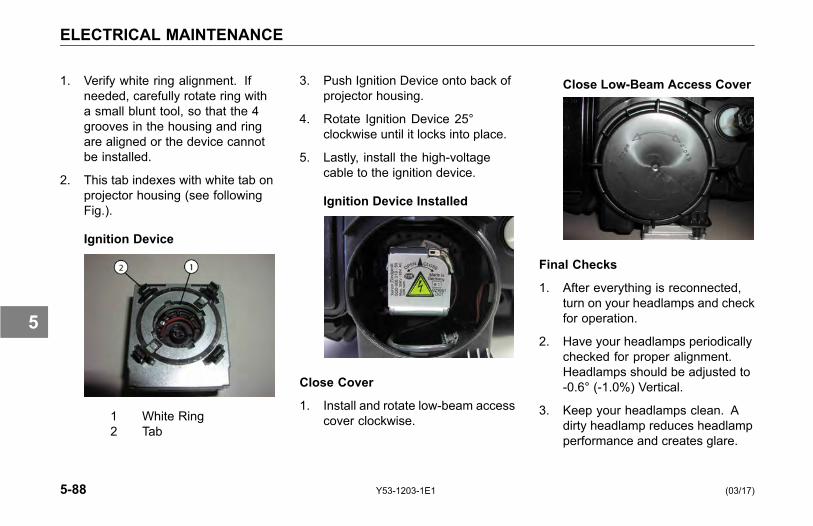
ELECTRICAL MAINTENANCE
1. Verify white ring alignment. Ifneeded, carefully rotate ring witha small blunt tool, so that the 4grooves in the housing and ringare aligned or the device cannotbe installed.
2. This tab indexes with white tab onprojector housing (see followingFig.).
Ignition Device
1 White Ring2 Tab
3. Push Ignition Device onto back ofprojector housing.
4. Rotate Ignition Device 25°clockwise until it locks into place.
5. Lastly, install the high-voltagecable to the ignition device.
Ignition Device Installed
Close Cover
1. Install and rotate low-beam accesscover clockwise.
Close Low-Beam Access Cover
Final Checks
1. After everything is reconnected,turn on your headlamps and checkfor operation.
2. Have your headlamps periodicallychecked for proper alignment.Headlamps should be adjusted to-0.6° (-1.0%) Vertical.
3. Keep your headlamps clean. Adirty headlamp reduces headlampperformance and creates glare.
5-88 Y53-1203-1E1 (03/17)
5
ELECTRICAL MAINTENANCE
° Use only clean soap andwater.
° Your headlamp is coated witha special substance to resistchips and hazing. Harshchemicals and polishing canremove this coating.
(03/17) Y53-1203-1E1 5-89
5
ENGINE MAINTENANCE
ENGINE MAINTENANCE
Engine Maintenance
WARNING!Exhaust fumes from the enginecontain carbon monoxide, a col-orless and odor less gas. Do notbreathe the engine exhaust gas.A poorly maintained, damaged orcorroded exhaust system can allowcarbon monoxide to enter the cab orsleeper. Entry of carbon monoxideinto the cab is also possible fromother vehicles nearby. Failure toproperly maintain your vehicle couldcause carbon monoxide to enterthe cab/sleeper and cause illness ordeath.
WARNING!Never idle your vehicle for prolongedperiods of time if you sense that ex-haust fumes are entering the cabor sleeper. Investigate the causeof the fumes and correct it as soonas possible. If the vehicle must bedriven under these conditions, driveonly with the windows open. Failureto repair the source of the exhaustfumes may result in personal injury,death, equipment or property dam-age.
NOTEKeep the engine exhaust systemand the vehicles cab/sleeper venti-lation system properly maintained.
It is recommended that the vehiclesexhaust system and cab/sleeper beinspected:
• By a competent technician every15,000 miles
• Whenever a change is noticed inthe sound of the exhaust system
• Whenever the exhaust system,underbody or cab or sleeper isdamaged
5-90 Y53-1203-1E1 (03/17)
5
ENGINE MAINTENANCE
Engine Lubrication
Refer to the engine manufacturer'sEngine Operation and MaintenanceManual supplied with your vehicle forinformation about draining and refillingengine oil, engine crank case capacity,engine oil type, and changing oil filters,etc.
WARNING!Hot engine oil can be dangerous.You could be burned. Let the en-gine oil cool down before changingit. Failure to comply may result inpersonal injury, death, equipment orproperty damage.
Lubricant Symbol KeyATF MD3 or MERCON®-approved automatic transmission fluid
BB High temperature ball bearing grease. Chevron SRI Mobile Grease HP, Texaco Multifax 2 or equivalent
CD50 SAE50W synthetic transmission fluid
CJ-4 Engine oil for PACCAR MX and Cummins ISX engines
CL Multipurpose chassis grease
EP Extreme Pressure Lubricant (Lithium 12-hydroxystearate base NGLI 2)
GL Straight mineral gear lubricant
HD Hypoid Gear Oil, A.P.I. - GL-5, SAE 75W-90FE synthetic gear lubricant
HT High Temperature grease (Timken Spec. 0-616)
MP Multipurpose gear lubricant (MIL-L-2105B)
DOT3 or DOT4 Brake Fluid
(03/17) Y53-1203-1E1 5-91
5

ENGINE MAINTENANCE
Inspection of the Engine Oil Level
NOTEIt takes approximately 15 minutesfor all the oil to run into the sumpwhen the engine is ‘warm.’ If thelevel is checked immediately afterswitching off the engine, the dipstickwill show a low oil level.
1. Make sure that the vehicle framerail is standing on a flat and levelsurface.
2. Make sure that the vehicle ishorizontal, both lengthwise andcrosswise. Check this carefullyon a vehicle with air suspension.Note that the engine may beinclined up to 4° depending on thevehicle model and wheelbase.
3. Twist the dipstick handle to unlockit, then pull the dipstick out of theholder.
4. Wipe the dipstick clean with alint-free cloth.
5. Place the dipstick back into theholder.
6. Pull the dipstick out again andcheck the oil level. The oil levelshould always be between the 2marks on the dipstick.
7. Reinstall the dipstick and twist tolock it in place.
1. Engine Oil High Level2. Engine Oil Low Level
5-92 Y53-1203-1E1 (03/17)
5
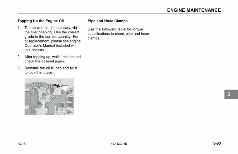
ENGINE MAINTENANCE
Topping Up the Engine Oil
1. Top up with oil, if necessary, viathe filler opening. Use the correctgrade in the correct quantity. Foroil replacement, please see engineOperator’s Manual included withthis chassis.
2. After topping up, wait 1 minute andcheck the oil level again.
3. Reinstall the oil fill cap and twistto lock it in place.
Pipe and Hose Clamps
Use the following table for torquespecifications to check pipe and hoseclamps.
(03/17) Y53-1203-1E1 5-93
5

ENGINE MAINTENANCE
Table 13 Pipe and Hose Clamp Torque Values
TORQUEAPPLICATION APPROVED CLAMPNm Lb-In
Radiator & Heat Exchanger Hoses Constant-Torque CT-L 10.2-12.5 90-110
Heater Hoses Constant Tension not required not required
Air Intake Pipes Hi-Torque HTM-L 11.3-14.2 100-125
Flex Seal 667 7.9-11.3 70-100Charge Air Intake Hoses
B9296 6-7 50-60
Fuel, Oil & Water Heat Exchangers(for hoses less than 9/16 diameter)
Miniature 3600L 1.1-1.7 10-15
Exhaust Clamps Breeze V-Band 54 480
Fuel System
Please follow these recommendationswhen you are changing your fuel filtersor strainer elements. Your vehicle'sengine will run better and last longer ifyou do. See the engine manufacturer'srecommendations for proper water andmicron requirements.
Installing Fuel Filters
When removing filters, cover anyelectrical equipment and wiring thatmight get soaked with fuel. Diesel fuelmay permanently damage electricalinsulation.
When installing spin-on (throwaway)filters:
1. Pre-fill filter with fuel.
2. Moisten gasket with diesel fuel.
3. Hand tighten them only to 1/2 - 2/3turn after gasket contact.Mechanical tightening of thesefilters may distort or crack the filterhead.
• When replacing a fuel filterelement, do not use a substitute.Install only filter elements designedfor fuel filtration. First clean and
5-94 Y53-1203-1E1 (03/17)
5
ENGINE MAINTENANCE
inspect the shell. Then insert thenew element and fill the containerat least 2/3 full of clean fuel beforeinstalling the shell.
NOTETo expel air from density-typestrainer elements, soak them inclean fuel before installing them.
• Throw away old gaskets. Replacethem with new ones to ensure apositive seal.
• Position the shell and gasketproperly. Then tighten the covernut or bolt just enough to preventfuel leakage.
• After starting the engine, check forleaks around the filter.
Filter Draining
1. Check fuel filter/water separatordaily. Check with engine OFF.Depending on the fuel storagefacility, more frequent drainingmay be required.
2. Open drain valve (by hand only):turn valve screw counter clockwiseapproximately 1 to 2 turns untildraining occurs. Drain filter sumpof water until clear fuel is visible.
3. If entrapped water exceeds sumpvolume, you can either:
4. Close valve and run engine untilsmooth idle is established, thenrepeat drain procedures.
5. Remove filter from mounting head,completely drain all fluid, andreassemble filter assembly. Besure to follow new filter assemblyinstructions.
6. Close drain valve by turning valvescrew clockwise approximately 1to 2 turns.
CAUTIONDo not overtighten the valve. Overtightening can damage the threads.
(03/17) Y53-1203-1E1 5-95
5
ENGINE MAINTENANCE
Accessory Drive Belts
You can avoid costly downtime byperiodically checking belt wear andreplacing worn and damaged belts.Neglect could cause belt failure. Theresult could be the loss of the electricalor air system as well as possibleengine damage from overheating. So,it is a good idea to check the beltsfrequently and replace them as soonas you detect trouble.
Engine FanThermatic (Clutch) Type Fan
WARNING!Do not work on the fan with the en-gine running. The engine fan canengage at any time without warning.Anyone near the fan when it turnson could be injured. Before turningon the ignition, be sure that no oneis near the fan. Failure to complymay result in personal injury, death,equipment or property damage.
To check the fan:
• Check the fan assembly mountingbolts for tightness. Inspect theblades for damage.
• Check the clutch operation bystarting the engine when it is cold.Then idle it at about 800 rpm.Listen for air leaks.
Fan Drive and Blade
Fan Blade Clearance: Around the fanshroud, the recommended distanceis 1 in. (25 mm) from front edge ofany fan blade-to-radiator side member.Minimum clearance is 3/4 in. (19 mm).
• Rear edge of any blade must beno closer than 3/8 in. (9 mm) tothe nearest engine component. Ifthis cannot be obtained, the fanspacer or fan is not correct.
• The leading edge of any fan blademust be 1 in. (25 mm) from theinside edge of the shroud.
5-96 Y53-1203-1E1 (03/17)
5
ENGINE MAINTENANCE
Engine Mounting
Periodic Inspection: Inspect enginemounts every 60,000 miles (96,560km). Check for the following:
• Inspect both mount and legfasteners. Check for looseor broken bolts. Replace asnecessary.
• Check mount and leg for fractures,breaks or deformation. Replaceas necessary.
• Check for complete insertionof motor mount. Replace asnecessary.
• New leg to mount flange headbolts should be torqued to 210-230lb-ft (284-311 Nm).
CAUTIONDo not re-torque or reuse existingflange head bolts. These bolts arefactory set to the specified torque.If bolts are loose or damaged, theymust be replaced with the new bolts.Failure to comply may result inequipment or property damage.
Exhaust System
The exhaust system is part of thenoise control system. Periodicallycheck the exhaust for wear and looseor missing parts. For details see Noiseand Emission Control on page 5-108.
(03/17) Y53-1203-1E1 5-97
5
ENGINE MAINTENANCE
All Models
Proper operation, driving techniquesand maintenance are key factors inobtaining the maximum service life ofthe muffler and/or converter. Someprecautions should be taken if theengine is equipped with a mufflerand converter. Avoid excess idling.Excessive idling or extended low loadperiods can cause the muffler andconverter to plug. A plugged mufflerand converter will lead to an increasein exhaust back pressure. Operatingthe engine in extremely cold conditionscan cause the muffler and converter toplug sooner. Use the procedure belowto clean out the muffler and converterif extended idle periods or extendedlow load periods are required.
1. Operate the engine at ratedconditions for five to fifteenminutes.
2. Contact an authorized EngineService Center, if the engine
continues to run at low poweror the engine does not respondproperly.
Multi-Function MessageDisplay
The Multi-function Display will displaydiagnostic messages that are intendedto alert you that trouble may bedeveloping in one of the systems, donot ignore these messages, they areimportant indicators that your vehicleshould be serviced immediately.
See your Kenworth Dealer for troubleshooting and diagnostic information.
5-98 Y53-1203-1E1 (03/17)
5
FRAME MAINTENANCE
FRAME MAINTENANCE
Introduction
WARNING!Do not cut, splice or weld framerails or drill through the top or bot-tom flanges of the rails. Theseoperations could affect frame railstrength leading to a failure resultingin an accident. Rail failures re-sulting from such modifications arenot warrantable. Failure to complymay result in personal injury, death,equipment or property damage.
Emergency Welding
Kenworth DOES NOT recommendframe welding. The high heat ofwelding nullifies the special heattreatment of the rails, greatly reducingthe tensile strength of the framerail. If a frame member becomescracked from overloading, fatigue,surface damage or a collision, the onlypermanent repair is to replace thedamaged frame member with a newpart. In an emergency, a temporaryrepair may be performed. Observethe following precautions to protectelectronic systems during weldingoperations.
Welding Precautions
In the event of emergency welding of aframe rail and when welding any otherpart of your truck or any componentattached to your truck, observe thefollowing precautions before welding:
• Disconnect all electronic devices.It is not possible to list all of theelectronics that could be affected,but a few examples include thefollowing: alternator, engineElectronic Control Unit (ECU),transmission ECU, ABS ECU,navigation devices, diagnosticdevices, and monitoring devices.
• Disconnect battery cables andinsulate them from the vehicle.
• Do not use the ECU or engineground stud for the ground of thewelding probe.
• Ensure that the ground connectionfor the welder is as close to theweld point as possible. Thisensures maximum weld currentand minimum risk to damageof electrical components on thevehicle.
(03/17) Y53-1203-1E1 5-99
5
FRAME MAINTENANCE
Painting
Do not electrostatically paint yourtruck or any component on yourtruck without first removing all ofthe electronic components from thetruck. It is not possible to list all ofthe electronics that could be affected,but a few examples include thealternator, engine Electronic ControlUnit (ECU), transmission ECU, ABSECU, navigation devices, diagnosticdevices, and monitoring devices.
Frame Fastener TorqueRequirements
• Tighten all frame fastenerswith a torque wrench. Torquespecifications apply to thefollowing fasteners with lightlylubricated threads.
NOTEWhenever possible, torque all framefasteners on the nut end, not the bolthead.
Fifth Wheel Maintenance
Proper preventive maintenance isessential to trouble-free service andsafe operation of the fifth wheel.
Every 2 Months or 25,000 Miles:
• Refer to specific manufacturer'sliterature for any specialinstructions.
• Steam clean the fifth wheel.
• Check lock guard operation usinga commercial lock tester.
• Clean and oil all moving parts.
• Lubricate the following part with alithium-base grease.
° Lock mechanism
• All grease fittings (especially thosewhich grease the top surface ofthe fifth wheel).
5-100 Y53-1203-1E1 (03/17)
5

FRAME MAINTENANCE
Every 6 Months or 50,000 Miles:
• Refer to specific manufacturer'sliterature for any specialinstructions.
• Remove fifth wheel from vehicle.Refer to the Kenworth ShopManual, "Fifth Wheel Removal."
• Steam clean the fifth wheel andmounting brackets.
• Check all moving parts forexcessive wear or damage.Replace all worn or broken parts.
• Complete two-month serviceprocedure.
• Install fifth wheel. Refer to theKenworth Shop Manual, "FifthWheel Installation."
Sliding Fifth Wheels
• Lubricate bearing surface ofsupport bracket through thegrease fittings on the side of thefifth wheel plate. Use a waterresistant lithium-base grease.
NOTEThe plate must be lifted up slightlyto relieve the weight of the bracketwhile applying grease.
Table 14 Standard Grade 8 UNF or UNCand Metric
TORQUE *FAS-TENERSIZE Nm lb-ft
5/16 22-30 16-22
3/8 41-54 30-40
7/16 75-88 55-65
1/2 109-122 80-90
9/16 156-190 115-140
5/8 224-265 165-195
TORQUE *FAS-TENERSIZE Nm lb-ft
3/4 394-462 290-340
7/8 517-626 380-460
1 952-1,129 700-830
1-1/8 1,346-1,591
990-1,170
1-1/4 1,877-2,217
1,380-1,630
METRIC WITH NYLON INSERT NUTSM5 8-12 6-9
M6 9-15 7-11
M8 23-31 17-23
M10 33-43 24-32
M12 75-101 55-75
M16 163-217 120-160
M20 352-460 260-340
* ESNA Style Lock Nut, with nylon insert.Lubricate nylon insert nut lightly with SAE20/30 oil.
(03/17) Y53-1203-1E1 5-101
5
FRONT AXLE AND SUSPENSION MAINTENANCE
FRONT AXLEAND SUSPENSIONMAINTENANCE
Axle Lubrication
See the axle manufacturer's operator'smanual for lubrication specificationsand service intervals.
Kingpin Lubrication
• Lubricate with approved lubricant.Lubricate knuckle thrust bearings,knuckle pins, and tie rod ends.See Table 6, RecommendedLubrication Intervals on page5-11. Lack of lubrication causespremature wear and hard steering.Lubrication schedule may beshortened if necessary.
Suspension Lubrication
Each standard spring anchor pin hasa grease fitting. Pressure lubricatespring pins as specified. See Table 6,Recommended Lubrication Intervalson page 5-11.
• At regular intervals, the springleaves may be lubricated with arust-inhibiting oil applied with aspray gun or brush.
• Depending on your suspension,lubricate all spring pins untilgrease flows out of both ends ofthe bushing. Look for signs of rustor water in the flushed grease.If a pin will not accept grease, itshould be removed, cleaned, andinspected.
CAUTIONDo not spray the suspension withchemical products or mineral oil; itcan cause damage to the bushings.
5-102 Y53-1203-1E1 (03/17)
5
FRONT AXLE AND SUSPENSION MAINTENANCE
Inspection• For all vehicles, mandatory
maintenance procedures includeretightening all U-bolts andinspecting the suspension forloose fasteners, abnormal wear,or damage. However, even withproper maintenance, the servicelife of leaf springs is affected bymany factors, such as: fatigue,vehicle gross weight, type ofload, road conditions, and vehiclespeed.
• Check for cracks, wear marks,splits, or other defects on thesurface of the spring. Defectiveparts must be replaced. Becauserepaired springs cannot befully restored to their originalservice life, replace the completeassembly if cracks or other defectsare detected.
• Visually inspect shock absorbersand rubber bushings.
Wheel Alignment
For driving safety and comfort, andto prolong the life of your vehicle, itis important to have wheels correctlyaligned. Check tire wear frequently.Uneven tire wear is a sign that thewheels may be misaligned.
If you see uneven wear, take yourvehicle to a Kenworth Dealer familiarwith aligning wheels on Kenworthvehicles.
U-Bolt Torque
It is important that U-bolts remain tight.Severe use of your vehicle will causethem to loosen faster. But all vehiclesneed to have their U-bolts checked andtightened regularly. Be sure someonewith the proper training and the righttools checks and tightens the U-boltson your Kenworth.
New springs can settle in after service,relieving the tension on the U-bolts.Loose U-bolts can cause leaf springbreakage, axle misalignment, hardsteering and abnormal tire wear.
• All vehicles should havesuspension U-bolts tightenedafter the first 500 miles (800 km) ofoperation. And re-torque the frontspring pinch bolts and shacklepinch bolts.
(03/17) Y53-1203-1E1 5-103
5
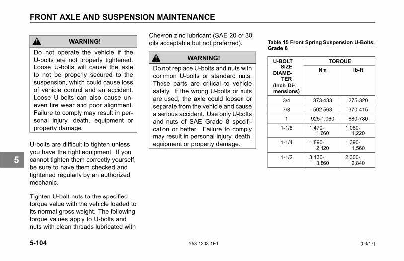
FRONT AXLE AND SUSPENSION MAINTENANCE
WARNING!Do not operate the vehicle if theU-bolts are not properly tightened.Loose U-bolts will cause the axleto not be properly secured to thesuspension, which could cause lossof vehicle control and an accident.Loose U-bolts can also cause un-even tire wear and poor alignment.Failure to comply may result in per-sonal injury, death, equipment orproperty damage.
U-bolts are difficult to tighten unlessyou have the right equipment. If youcannot tighten them correctly yourself,be sure to have them checked andtightened regularly by an authorizedmechanic.
Tighten U-bolt nuts to the specifiedtorque value with the vehicle loaded toits normal gross weight. The followingtorque values apply to U-bolts andnuts with clean threads lubricated with
Chevron zinc lubricant (SAE 20 or 30oils acceptable but not preferred).
WARNING!Do not replace U-bolts and nuts withcommon U-bolts or standard nuts.These parts are critical to vehiclesafety. If the wrong U-bolts or nutsare used, the axle could loosen orseparate from the vehicle and causea serious accident. Use only U-boltsand nuts of SAE Grade 8 specifi-cation or better. Failure to complymay result in personal injury, death,equipment or property damage.
Table 15 Front Spring Suspension U-Bolts,Grade 8
TORQUEU-BOLTSIZE
DIAME-TER
(Inch Di-mensions)
Nm lb-ft
3/4 373-433 275-320
7/8 502-563 370-415
1 925-1,060 680-780
1-1/8 1,470-1,660
1,080-1,220
1-1/4 1,890-2,120
1,390-1,560
1-1/2 3,130-3,860
2,300-2,840
5-104 Y53-1203-1E1 (03/17)
5
HEATER AND AIR CONDITIONER MAINTENANCE
HEATER AND AIRCONDITIONERMAINTENANCE
Introduction
The combination heater-air conditionerprovides comfort for those in the cabthrough accurate control of the cabenvironment in all weather conditions.Regular attention to the items belowwill help you keep the heater-airconditioner unit running well.
NOTEKeep the vehicles ventilation sys-tem, engine exhaust system andcab/sleeper joints properly main-tained.
It is recommended that the vehiclesexhaust system and cab/sleeper beserviced as follows:
• Inspected by a competenttechnician every 15,000 miles(24,000 km)
• Whenever a change is noticed inthe sound of the exhaust system
• Whenever the exhaust system,underbody or cab or sleeper isdamaged
NOTETo allow for proper operation of thevehicle ventilation system, proceedas follows:
• Keep the inlet grille at the base ofthe windshield clear of snow, ice,leaves and other obstructions atall times.
• Keep the exhaust pipe area clearto help reduce the buildup ofexhaust gas under the vehicle.
Special Precautions
WARNING!Excessive heat may cause the pres-surized components of the air con-ditioning system to explode. Neverweld, solder, steam clean, or usea blow torch near any part of theair conditioning system. Failure tocomply may result in personal injury,death, equipment or property dam-age.
WARNING!If a refrigerant leak develops in thepresence of excessive heat or anopen flame, hazardous gases maybe generated. These gases maycause unconsciousness or death.
(03/17) Y53-1203-1E1 5-105
5
HEATER AND AIR CONDITIONER MAINTENANCE
• If you become aware of arefrigerant leak on your vehiclehave your system serviceimmediately and observe thefollowing precautions:
° Stay away from the hotengine until the exhaustmanifold has cooled.
° Do not permit any openflame in the area. Even amatch or a cigarette lightermay generate a hazardousquantity of poisonous gas.
° Do not smoke in the area.Inhaling gaseous refrigerantthrough a cigarette maycause violent illness.
Heater• Check all heater controls for
full-range operation.
• Check hoses, connections, andheater core for condition andleaks.
• Check the drain tube of the freshair inlet for trapped water beforeassuming that there is a leak in theheating system. If the heater coreis leaking, a reliable radiator shopshould be able to repair it.
• Check the heater core for debrisblocking the air flow. If the blowerand air controls are functioningproperly, yet the heater is notoperating properly, the heatercore or the hot water valves maybe clogged or closed. Clean theheater core if necessary. If thecondition persists, take the vehicleto a Kenworth Dealer for properheater service or repair.
CAUTIONDuring extreme cold weather, do notblow hot defroster air onto cold wind-shields. This could crack the glass.Turn the air direction lever to Defrostand adjust the fan speed accordinglywhile the engine warms. If the en-gine is already warm, move the tem-perature selector to Cool, then grad-ually increase the temperature whenyou see that the windshield is start-ing to warm-up.
5-106 Y53-1203-1E1 (03/17)
5
HEATER AND AIR CONDITIONER MAINTENANCE
Air Conditioner
WARNING!The air conditioning system is underpressure. If not handled properlyduring servicing, it could explode.Any servicing that requires depres-surizing and recharging the air con-ditioning system must be conductedby a qualified technician with theright facilities to do the job. Failureto comply may result in personalinjury, death, equipment or propertydamage.
• Check the compressor and driveclutch for noise and vibration.If you find problems, have thesystem checked thoroughly. Amalfunctioning clutch usuallyindicates trouble elsewhere in thesystem.
• Check the evaporator core, filter,and condenser core for debrisrestricting air flow. Clean if
necessary. Small particles maybe removed with compressedair blown through the core in theopposite direction of normal airflow.
WARNING!Wear eye protection any time youblow compressed air. Small parti-cles blown by compressed air couldinjure your eyes.
• Inspect and clean cab air filterelement every 3 - 6 monthsof service. Depending on theoperating environment, if air flowfrom the air conditioner and heateris less efficient or windows fogeasier, you may need to replacethe cab air filter.
• Check the compressor belt forcondition and proper tension.
• Check all hoses for kinks,deterioration, chafing, and leaks.
Adjust kinked or chafing hoses toeliminate restrictions and preventfurther wear.
• Check all components andconnections for refrigerant leaks.If you discover a leak, do not try totighten a connection. Tighteninga connection may cause a worseleak. Have a qualified techniciancorrect the problem.
NOTEA leaking evaporator or condensercore cannot be repaired; it must bereplaced.
Have the air conditioning system fullyserviced annually by your KenworthDealer. Qualified service technicianswill have to evacuate and recharge thesystem.
(03/17) Y53-1203-1E1 5-107
5

NOISE AND EMISSION CONTROL MAINTENANCE
NOISE ANDEMISSION CONTROLMAINTENANCE
Noise Emission Warranty
Kenworth Truck Company warrantsto the first person who purchases thisvehicle (for purposes other than resale)and to each subsequent purchaser:that this vehicle, as manufacturedby Kenworth Truck Company, wasdesigned, built and equipped toconform, at the time it left Kenworth'scontrol, with all applicable U.S. EPANoise Control Regulations.
This warranty covers this vehicleas designed, built and equipped byKenworth, and is not limited to anyparticular part, component or system ofthe vehicle manufactured by Kenworth.Defects in design, assembly or in anypart, component or system of thevehicle as manufactured by Kenworth,
which at the time it left Kenworth'scontrol caused noise emissionsto exceed Federal standards, arecovered by this warranty for the life ofthe vehicle.
Tampering with Noise ControlSystem
Federal law prohibits the followingacts or the causing thereof:
1. The removal or renderinginoperative by any person otherthan for purposes of maintenance,repair, or replacement, of anydevice or element of designincorporated into any new vehiclefor the purpose of noise controlprior to its sale or delivery to theultimate purchaser or while it is inuse, or
2. The use of the vehicle after suchdevice or element of designhas been removed or renderedinoperative by any person.
Among those acts presumed toconstitute tampering are the acts listedbelow:
5-108 Y53-1203-1E1 (03/17)
5
NOISE AND EMISSION CONTROL MAINTENANCE
Air Intake System
• Removing or rendering inoperativethe air cleaner/silencers or intakepiping.
Engine Cooling System
• Removing or rendering inoperativethe fan clutch.
• Removing the fan shroud.
Engine
• Removing or rendering enginespeed governor inoperative so asto allow engine speed to exceedmanufacturer's specifications.
• Modifying ECU parameters.
Exhaust System
• Removing or rendering inoperativeexhaust system components.
Fuel System
• Removing or rendering enginespeed governor inoperative,allowing engine speed to exceedmanufacturer's specifications.
• Removing of air signal attenuatoron engines equipped with thisdevice.
Inner Fender Shields and Cab Skirts
• Removing shield or skirts.
• Cutting away parts of shields,skirts or damaged or looseportions of shields or skirts.
Noise Insulating Blankets
• Removing noise insulators fromengine block or from around theoil pan.
• Cutting holes in, or cutting awaypart of noise insulators.
• Removing hood-mounted noiseinsulation.
(03/17) Y53-1203-1E1 5-109
5
NOISE AND EMISSION CONTROL MAINTENANCE
Inspection and MaintenanceInstructions
The following instructions are based oninspection of the noise control systemat regular intervals as indicated in theNoise Control System MaintenanceLog on page 5-116.
If, during periodic inspection andmaintenance of other systems andcomponents, it is found that parts of thenoise control system require attention,we recommend that those parts beinspected at more frequent intervalsto assure adequate maintenance andperformance.
Air Intake System
• Do all checks and maintenanceprocedures listed in this manualunder Engine Air Intake Systemand Air Cleaner. See Air Dryer onpage 4-17.
• Check the induction tubing, elbowconnections, clamps, brackets,and fasteners for deterioration,cracks, and security.
• If you find an air leak anywherebetween the air cleaner andthe engine, repair that leakimmediately.
CAUTIONAir leaks cause excessive noise andmay result in serious damage to theengine. If you do not repair them theengine damage will not be coveredby your warranty. Repair all air leaksas soon as you find them.
Engine Mounted Noise Insulators
• Check condition. Is the insulatorsecure? How you do this willdepend on the method of attachingthe noise insulators on the engineand around the oil pan (bolts,snap fasteners, or straps). Tightenloose fasteners and repair orreplace any worn or damagedfasteners.
• Check insulators around fastenersand stress points, especiallywhere they may be affected byengine vibration. Repair anycracked or damaged mountingpoints. Use suitable reinforcingplates to ensure that the insulatorswill remain in position.
5-110 Y53-1203-1E1 (03/17)
5
NOISE AND EMISSION CONTROL MAINTENANCE
Exhaust System
• Check for exhaust leaks,which would indicate a leakingmanifold gasket; replace gasket ifnecessary.
• Check cap screws for tightness,including those at the flanges.Refer to the engine manufacturer'sservice manual for propertightening sequence and torquevalues.
Joints and Clamps
• Check for leaks, and tighten asnecessary. Check for deteriorationor dents in pipes and clamps whichcould allow exhaust to escape.
Selective Catalyst Reduction (SCR)
• Check SCR canister filter, clampsand mounting brackets. Tighten ifnecessary. Inspect SCR canisterfor signs of rust or corrosion.
(03/17) Y53-1203-1E1 5-111
5

NOISE AND EMISSION CONTROL MAINTENANCE
Exhaust Piping
• Check exhaust piping for rust,corrosion, or damage. Replacedeteriorated piping before holesappear. If piping is perforated atany point, temporary patching orlagging is acceptable until you canhave permanent repairs made.On turbocharged engines, checkjoints at flanges and mountingbrackets for tightness.
Diesel Particulate Filters (DPF)
• Check the DPF, clamps, andmounting brackets. Tighten ifnecessary. Inspect the DPF forsigns of rust or corrosion.
• Check internal baffling. You cando this by listening for rattlingsounds while tapping on the DPFwith a rubber mallet or revving theengine up and down through itsnormal operating range.
Mufflers
• Check muffler, clamps, andmounting brackets. Tighten ifnecessary. Inspect muffler forsigns of rust or corrosion.
• Check internal baffling. You cando this by listening for rattlingsounds while tapping the mufflerwith a rubber mallet or revving theengine up and down through itsnormal operating range.
5-112 Y53-1203-1E1 (03/17)
5
NOISE AND EMISSION CONTROL MAINTENANCE
Exhaust Tail Pipe
• Check the mounting. Tighten asnecessary. The miter cut at the tipof the pipe must be facing the rearof the vehicle. Do not modify theend of the pipe in any way.
Engine Fan and Shroud
WARNING!Do not work on the fan with the en-gine running. The engine fan canengage at any time without warning.Anyone near the fan when it turnson could be injured. Before turningon the ignition, be sure that no oneis near the fan. Failure to complymay result in personal injury, death,equipment or property damage.
• Check all fasteners for tightness.Check for stress cracks in theshroud. Make sure the shroud isadjusted so that it does not touchthe fan blades.
• Check to verify that the fan isdisengaged (not turning) withthe engine running at normaloperating temperatures (from coldto the point that the fan engages).
• Check fan blade mounting bolts.Inspect fan blades to be sure theyare not cracked or bent.
(03/17) Y53-1203-1E1 5-113
5
NOISE AND EMISSION CONTROL MAINTENANCE
Transmission and Driveline
• Substituting a different maintransmission or drivelinecomponents, other thandesign-specified units, mayresult in increased vehicle noiseemission.
Hood Insulation Blanket
• Check all fasteners for conditionand security. Repair or replaceany broken or defective fasteners.
Blanket
• Check for chafing or tears. Patchit if necessary. Find the cause ofthe damage. If any componentor accessory is causing wear ordamage and cannot be relocated,put reinforcing pads on the blanketat the site of wear.
5-114 Y53-1203-1E1 (03/17)
5

NOISE AND EMISSION CONTROL MAINTENANCE
Inner Fender Shields and Cab Skirts
• Check all fasteners, especially theself-tapping hex head screws. Arethey secure? Remove and replaceany loose rivets.
Shields and Skirts
• Check shields and skirts for cracksat mounting and stress points.Check fender shields for tiremarks, worn spots, or damagefrom objects thrown from tiretreads. You can repair cracked ordamaged fiberglass fender shieldswith fiberglass and resin.
• If you find damage at a fasteningpoint, you can gain additionalstrength by installing a suitablereinforcing plate. This plateshould be drilled to accept a rivetand laminated to the shield withfiberglass and resin.
• Check cab skirts, sills, andbrackets for overall conditionand repair them as necessary.Damaged rubber fender shieldsor cab skirting cannot be repaired.You will need to replace it.
NOTEYour Kenworth Dealer can performall of these checks and repairs orreplacements.
(03/17) Y53-1203-1E1 5-115
5
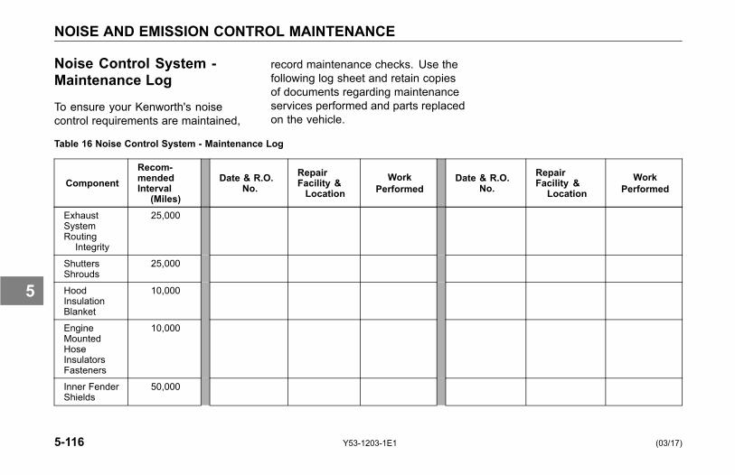
NOISE AND EMISSION CONTROL MAINTENANCE
Noise Control System -Maintenance Log
To ensure your Kenworth's noisecontrol requirements are maintained,
record maintenance checks. Use thefollowing log sheet and retain copiesof documents regarding maintenanceservices performed and parts replacedon the vehicle.
Table 16 Noise Control System - Maintenance Log
ComponentRecom-mendedInterval
(Miles)
Date & R.O.No.
RepairFacility &Location
WorkPerformed
Date & R.O.No.
RepairFacility &
LocationWork
Performed
ExhaustSystemRouting
Integrity
25,000
ShuttersShrouds
25,000
HoodInsulationBlanket
10,000
EngineMountedHoseInsulatorsFasteners
10,000
Inner FenderShields
50,000
5-116 Y53-1203-1E1 (03/17)
5
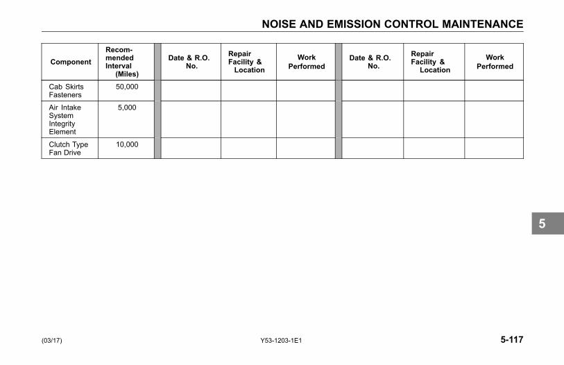
NOISE AND EMISSION CONTROL MAINTENANCE
ComponentRecom-mendedInterval
(Miles)
Date & R.O.No.
RepairFacility &Location
WorkPerformed
Date & R.O.No.
RepairFacility &
LocationWork
Performed
Cab SkirtsFasteners
50,000
Air IntakeSystemIntegrityElement
5,000
Clutch TypeFan Drive
10,000
(03/17) Y53-1203-1E1 5-117
5
REAR AXLE AND SUSPENSION MAINTENANCE
REAR AXLE ANDSUSPENSIONMAINTENANCE
General Maintenance
WARNING!Do not work on the vehicle withoutthe parking brake set and wheelschocked securely. If the vehicle isnot secured to prevent uncontrolledvehicle movement, it could roll andmay result in personal injury, death,equipment or property damage.
NOTEUse wood blocks (4 in. X 4 in. orlarger) against the front and rear sur-faces of the tires. Be sure the vehi-cle cannot move.
Your vehicle's suspension, bydesign, requires a minimal amount ofmaintenance. However, suspensions
in over-the-road operations requireperiodic inspection to ensure trouble-free performance.
WARNING!Failure to maintain the specifiedtorque values or to replace wornparts can cause component systemfailure, possibly resulting in an ac-cident. Improperly tightened (loose)suspension U-bolts can lead to un-safe vehicle conditions, including:hard steering, axle misalignment,spring breakage or abnormal tirewear. See Front Spring SuspensionU-bolts on page 5-104 for propertorque specifications. Failure tocomply may result in personal injury,death, equipment or property dam-age.
WARNING!Do not operate the vehicle if theU-bolts are not properly tightened.Loose U-bolts will cause the axleto not be properly secured to thesuspension, which could cause lossof vehicle control and an accident.Loose U-bolts can also cause un-even tire wear and poor alignment.Failure to comply may result in per-sonal injury, death, equipment orproperty damage.
CAUTIONDo not spray the suspension withchemical products or mineral oil; itcan cause damage to the bushings.
NOTEFailure to follow these recommenda-tions could void warranty.
5-118 Y53-1203-1E1 (03/17)
5
REAR AXLE AND SUSPENSION MAINTENANCE
Visual Inspection
For all vehicles, mandatorymaintenance procedures includeretightening of U-bolts and completeinspection. However, even with propermaintenance, many factors affect theservice life of springs and suspensioncomponents, such as: fatigue, vehiclegross weight, type of load, roadconditions and vehicle speed.
It is important that U-bolts remain tight.Severe use of your vehicle can causethem to loosen faster. But all vehiclesneed to have their U-bolts checked andtightened regularly. Be sure someonewith the proper training and the righttools checks and tightens the U-boltson your Kenworth.
• After the first 500 miles (800 km) ofoperation, inspect the suspensionperiodically, as noted below:
• Visually check for loose or missingfasteners, cracks in hanger or axleconnection brackets.
• Check that springs are centered inhangers and in good condition.
• Check for cracks, wear marks,splits, or other defects on thesurface of the spring.
• Replace defective parts. Becauserepaired springs cannot befully restored to their originalservice life, replace the completeassembly if cracks or other defectsare detected.
• After replacement of any part ordiscovery of loose components,check the torque of all fasteners.
• New springs settle-in after thevehicle's initial service, causingthe U-bolts to become loose.
Rear Suspension Fasteners
To maintain the performance of theair suspension, check fastener torquevalues after the first 2,000 miles (3,218km) of service and every 60,000 miles(96,000 km) thereafter.
Torque recommendations apply tofasteners supplied and installedby Kenworth. The values listed inTable 17 and Table 18 below, are forcadmium plated or phosphate and oilfasteners only.
U-bolts are difficult to tighten unlessyou have the right equipment. If youcannot tighten them correctly yourself,be sure to have them checked andtightened regularly by an authorizedmechanic.
(03/17) Y53-1203-1E1 5-119
5
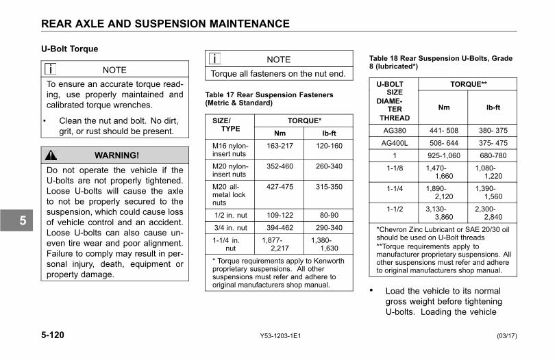
REAR AXLE AND SUSPENSION MAINTENANCE
U-Bolt Torque
NOTETo ensure an accurate torque read-ing, use properly maintained andcalibrated torque wrenches.
• Clean the nut and bolt. No dirt,grit, or rust should be present.
WARNING!Do not operate the vehicle if theU-bolts are not properly tightened.Loose U-bolts will cause the axleto not be properly secured to thesuspension, which could cause lossof vehicle control and an accident.Loose U-bolts can also cause un-even tire wear and poor alignment.Failure to comply may result in per-sonal injury, death, equipment orproperty damage.
NOTETorque all fasteners on the nut end.
Table 17 Rear Suspension Fasteners(Metric & Standard)
TORQUE*SIZE/TYPE Nm lb-ft
M16 nylon-insert nuts
163-217 120-160
M20 nylon-insert nuts
352-460 260-340
M20 all-metal locknuts
427-475 315-350
1/2 in. nut 109-122 80-90
3/4 in. nut 394-462 290-340
1-1/4 in.nut
1,877-2,217
1,380-1,630
* Torque requirements apply to Kenworthproprietary suspensions. All othersuspensions must refer and adhere tooriginal manufacturers shop manual.
Table 18 Rear Suspension U-Bolts, Grade8 (lubricated*)
TORQUE**U-BOLTSIZE
DIAME-TER
THREADNm lb-ft
AG380 441- 508 380- 375
AG400L 508- 644 375- 475
1 925-1,060 680-780
1-1/8 1,470-1,660
1,080-1,220
1-1/4 1,890-2,120
1,390-1,560
1-1/2 3,130-3,860
2,300-2,840
*Chevron Zinc Lubricant or SAE 20/30 oilshould be used on U-Bolt threads**Torque requirements apply tomanufacturer proprietary suspensions. Allother suspensions must refer and adhereto original manufacturers shop manual.
• Load the vehicle to its normalgross weight before tighteningU-bolts. Loading the vehicle
5-120 Y53-1203-1E1 (03/17)
5
REAR AXLE AND SUSPENSION MAINTENANCE
ensures proper adjustment of theU-bolt and spring assembly.
WARNING!Do not replace U-bolts and nuts withcommon U-bolts or standard nuts.These parts are critical to vehiclesafety. If the wrong U-bolts or nutsare used, the axle could loosen orseparate from the vehicle and causea serious accident. Use only U-boltsand nuts of SAE Grade 8 specifi-cation or better. Failure to complymay result in personal injury, death,equipment or property damage.
Rear Axle Lubrication
See the axle manufacturer's operator'smanual for lubrication specificationsand service intervals.
Rear Axle Alignment
Continual road shock and loadstresses may force the rear axlesout of alignment. If you detect rapidtire wear on the rear axles, you mayhave misaligned axles. If you suspectrapid tire wear, have your rear axlealignment checked and adjusted by aKenworth Dealer.
In addition to pre-delivery inspections,suspension alignment should bechecked when any one of the followingconditions exist:
• Discovery of loose suspensionfasteners. (Loose, defined as anytorque below the recommendedtorque value.)
• Discovery of elongated holes in asuspension component.
• Bushing replacement.
• Excessive or abnormal tire wear.
(03/17) Y53-1203-1E1 5-121
5

STEERING AND DRIVELINE MAINTENANCE
STEERING ANDDRIVELINEMAINTENANCE
Power Steering
Oil (under low pressure) provides thepower to operate the steering gear. Italso serves to lubricate moving partsand remove heat. A loss of steeringefficiency will occur if too much heatbuilds up in the system.
WARNING!Do not operate the vehicle if thesteering system is not working prop-erly. You could lose control of yourvehicle if the steering system is notin good working condition, whichcould result in a serious accident.For driving safety, visually checkthe steering gear and components.Frequent checks are important fordriving safety, especially after trav-eling over rough roads. Failure tocomply may result in personal injury,death, equipment or property dam-age.
NOTEIf the steering feels unbalanced fromside-to-side while turning, check forthe following possible causes:
• unequal tire pressures
• vehicle overloaded or unevenlydistributed load
• wheels out of alignment
• wheel bearings improperlyadjusted
If you cannot correct the problem,check with an authorized KenworthDealer.
The Kenworth is equipped with integralpower steering. The system includesan engine-driven fluid pump, a fluidreservoir, the steering gear, andconnecting hoses. Because of thehydraulic power assist, little effort isrequired to turn the steering wheel.When no input is applied through thesteering wheel, the steering gear willreturn to the neutral position. If, forany reason, the power assist systemgoes out, steering the vehicle is stillpossible, yet it will require muchgreater effort.
5-122 Y53-1203-1E1 (03/17)
5
STEERING AND DRIVELINE MAINTENANCE
Visually check the following parts:
• Crosstube: Is it straight?
• Draglink tube clamp: Check forlooseness or interference.
• Ball joints and steering U-joints:Check for looseness.
• Steering wheel for excessivefree-play. Check the simplestprobable causes first:
° unequal tire pressures
° loose cap nuts
° bent crosstube
° lack of lubrication
• If these checks do not reveal theproblem, or if you correct themand still have a steering problem,take your truck to an authorizedKenworth Dealer for evaluation.
Fluid Level and Refill
Have the power steering fluid andfilters changed at an authorizedKenworth Dealer.
• Check and completely changethe fluid level according to Table6, Recommended LubricationIntervals on page 5-11. Use thefollowing procedure:
NOTEBefore removing reservoir cover,wipe outside of cover so that no dirtcan fall into the reservoir.
• Maximum/Minimum level isindicated on the reservoir. Thesesame levels are also indicated bytwo lines on the dipstick in thereservoir.
• There are two ways to checkwhether the power steering fluid
is at its proper level. Both checksare with the engine NOT running.
1. If you check the fluid with theengine and steering systemCOLD, the fluid level should beat/or above the Minimum indicatorlevel and should generally notexceed the middle point betweenMaximum and Minimum levelindicators.
2. If you check the fluid with theengine and steering systemWARM, the fluid should NOTexceed the Maximum levelindicator and should generallynot drop below the middle pointbetween the Maximum andMinimum level indicators.
(03/17) Y53-1203-1E1 5-123
5

STEERING AND DRIVELINE MAINTENANCE
Fluid Refill
The following recommendations arefor general purpose steering systems,commonly installed on Kenworthvehicles.
• For normal temperatures, useAutomatic Transmission Fluid(ATF) Type E or F or Dexron® II.
• For cold temperatures of -22º F(-30º C) and above use ATF TypeA.
• For extremely cold temperaturesbetween -22º F (-30º C) and -40ºF (-40º C) use ATF Type B.
Steering Driveline
The following are common torquespecifications for most drivelines.
• Torque on U–joint pinch bolt andnut (7/16 in) 74–81 Nm (55 to 60lb-ft), lubricated.
• Torque on Pitman arm clamp boltand nut (3/4 in): 406–433 Nm (300to 320 lb-ft), lubricated.
• For off–highway vehicles, tightenthe U–bolts after the first day ortwo of operation. Then checkweekly.
WARNING!If any part of the steering system(e.g. linkage, steering driveline, col-umn, front-end alignment, etc) is re-paired, removed, or disassembled inany way, or if the steering angle sen-sor is replaced, the steering anglesensor must be recalibrated. Failureto do so could cause loss of vehiclecontrol. Any repairs or adjustmentsto any part of the steering systemmust be performed by an authorizedKenworth Dealer. Failure to complymay result in personal injury, death,equipment or property damage.
5-124 Y53-1203-1E1 (03/17)
5
STEERING AND DRIVELINE MAINTENANCE
Driveshaft
See the driveshaft manufacturer'soperator's manual for lubricationspecifications and service intervals.
(03/17) Y53-1203-1E1 5-125
5
TIRES AND WHEEL MAINTENANCE
TIRES AND WHEELMAINTENANCE
Introduction
Keeping the tires in good condition isessential to the safe, efficient operationof your Kenworth. Regular, frequentinspection and the right care will giveyou the assurance of safe and reliabletire operation.
WARNING!Use only original equipment manu-factured (OEM) components. Use ofnon-original equipment could causewheel breakage and wheel separa-tion from vehicle. Failure to complymay result in personal injury, death,equipment or property damage.
WARNING!Always support the vehicle with ap-propriate safety stands if it is neces-sary to work underneath the vehicle.A jack is not adequate for this pur-pose. Failure to comply may resultin personal injury, death, equipmentor property damage.
General SafetyRequirements• Each mounting system is
engineered only for use with itscorrect mating part. Be sure thatproperly matched componentsare used for each type ofmounting. The comparisonchart, Comparing Hub-pilotedand Ball-seat Wheels onpage 5-136, illustrates thedifferences between parts usedin hub-piloted mount and ballseat mount applications. OnlyOEM supplied hub-piloted orball-seat mounted wheels maybe used on this vehicle.
• If you are not fully qualified andnot equipped with the propertools and equipment, do notattempt to raise the vehicle orremove or install the damagedtire and wheel assembly. Obtainexpert help. A person can be
5-126 Y53-1203-1E1 (03/17)
5
TIRES AND WHEEL MAINTENANCE
injured and/or damage canresult from using the wrongservice methods. Truck tiresand wheels should be servicedonly by trained personnel usingproper equipment. Do notreinflate a tire that has been runflat or is low on air without firstremoving the tire from the rimand inspecting for damage.
• Follow OSHA regulations persection 1910.177.
• Do not exceed the speed ratingof tires. Exceeding the speedrating may result in suddentire failure and loss of vehiclecontrol.
• Follow all warnings andcautions contained within thetire and wheel manufacturersliterature.
• Only properly trained personnelshould service tire and rimassemblies.
Speed Restricted Tires
WARNING!This vehicle may be equipped withspeed restricted tires. Check eachtires sidewall for maximum ratedspeed. Vehicle should not be oper-ated at sustained speed in excessof maximum rated speed. Failureto comply with these speed restric-tions could cause sudden tire failurewhich may result in personal injury,death, equipment or property dam-age.
(03/17) Y53-1203-1E1 5-127
5

TIRES AND WHEEL MAINTENANCE
Tire Inspection andReplacement
Visually inspect your tires frequentlyfor any abnormal conditions such asscrapes, bulges, and uneven wear.This must be done immediately afterknown or suspected contact with anobject in the road, with a pothole,road irregularity or after severebraking. Refer these conditions to anAuthorized Tire Service Center forrepair or replacement. Never drive ona tire if such conditions appear.
If the tire looks under-inflated, standoff to the side and check for damageto the wheel assembly. This can bedone by visually comparing the wheelin question to other wheels on thevehicle. For dual wheel assemblies,check between the wheels for damage.If any damage is found, or you suspectdamage, do not attempt further repair.Call for expert tire service.
Tire Inflation and Loading
Low pressure is a tire's worst enemy.Under-inflation allows tires to fleximproperly, causing high temperaturesto build up. Heat causes early tiredamage such as flex break, radialcracks, and ply separation. And lowpressure may affect control of yourvehicle, especially at the front wheels.
WARNING!Do not operate vehicle with under-inflated tires. The extra heat causedby under-inflation can cause suddentire failure such as a tire fire or blowout. Low pressure may affect controlat the front wheels, which could re-sult in an accident. Keep your tiresinflated to the manufacturer's rec-ommended air pressure. Failure tocomply may result in personal injury,death, equipment or property dam-age.
Tire Inflation
Most tire wear problems are causedby under-inflation as the result ofslow leaks. So you will want to checktire pressure regularly. Give the tiresa visual test every day, and checkinflation with a gauge every week.
When checking tire pressure, inspecteach tire for damage to sidewalls,cuts, cracks, uneven wear, rocksbetween dual wheels (tires), etc. If atire appears under-inflated, check fordamage to the wheel assembly. Do notforget to check between dual wheels.If you find wheel damage, have anexpert tire service repair it.
5-128 Y53-1203-1E1 (03/17)
5

TIRES AND WHEEL MAINTENANCE
WARNING!Do not repair damaged tires unlessyou are fully qualified and equippedto do so. Wheel and tire assem-blies cannot be worked on withoutproper tools and equipment, suchas: safety cages or restraining de-vices. Have all tire repairs per-formed by an expert. And standaway from the tire assembly whilethe expert is working. Failure tocomply may result in personal injuryor death.
CAUTIONPressure should be checked whenthe tires are cool. Warm or hot tirescause pressure buildup and will giveyou an inaccurate reading. So neverdeflate a warm tire to the specifiedpressure. Failure to comply may re-sult in equipment damage.
Under-inflated tires will adverselyaffect the operation of the vehicleand tires:
• making steering difficult
• causing extra strain on the tiresidewalls
• reducing the tread life of tiresdue to the high temperaturesgenerated from excess flexing ofthe tire
Inflate tires to the manufacturer's coldair pressure specification molded intothe tire side wall.
Lower tire pressure does not giveyou more traction on ice or snow.under-inflation actually reducestraction and steering control. See thetire manufacturer's Driver's Handbookfor more information on properoperation and use of tires.
1
TREADCONTACT WITH
ROAD
Proper-Inflation:the correct profilefor full contact withthe road.
2
TREADCONTACTWITH
ROAD
Under-Inflation:causes abnormaltire deflection, whichbuilds up excessiveheat, running therisk of failure. Italso causes irregularwear.
(03/17) Y53-1203-1E1 5-129
5
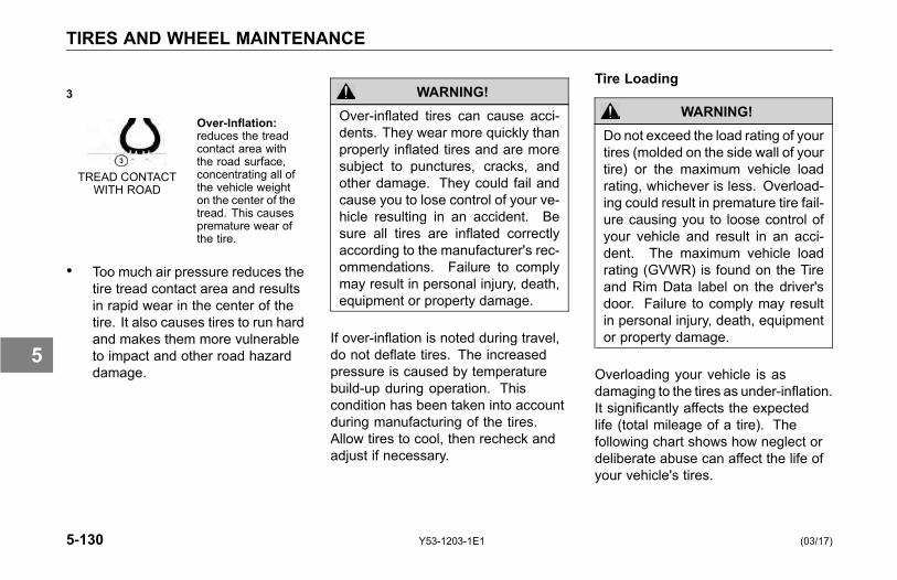
TIRES AND WHEEL MAINTENANCE
3
TREAD CONTACTWITH ROAD
Over-Inflation:reduces the treadcontact area withthe road surface,concentrating all ofthe vehicle weighton the center of thetread. This causespremature wear ofthe tire.
• Too much air pressure reduces thetire tread contact area and resultsin rapid wear in the center of thetire. It also causes tires to run hardand makes them more vulnerableto impact and other road hazarddamage.
WARNING!Over-inflated tires can cause acci-dents. They wear more quickly thanproperly inflated tires and are moresubject to punctures, cracks, andother damage. They could fail andcause you to lose control of your ve-hicle resulting in an accident. Besure all tires are inflated correctlyaccording to the manufacturer's rec-ommendations. Failure to complymay result in personal injury, death,equipment or property damage.
If over-inflation is noted during travel,do not deflate tires. The increasedpressure is caused by temperaturebuild-up during operation. Thiscondition has been taken into accountduring manufacturing of the tires.Allow tires to cool, then recheck andadjust if necessary.
Tire Loading
WARNING!Do not exceed the load rating of yourtires (molded on the side wall of yourtire) or the maximum vehicle loadrating, whichever is less. Overload-ing could result in premature tire fail-ure causing you to loose control ofyour vehicle and result in an acci-dent. The maximum vehicle loadrating (GVWR) is found on the Tireand Rim Data label on the driver'sdoor. Failure to comply may resultin personal injury, death, equipmentor property damage.
Overloading your vehicle is asdamaging to the tires as under-inflation.It significantly affects the expectedlife (total mileage of a tire). Thefollowing chart shows how neglect ordeliberate abuse can affect the life ofyour vehicle's tires.
5-130 Y53-1203-1E1 (03/17)
5

TIRES AND WHEEL MAINTENANCE
Table 19 Effect of Load Pressure on Tire Life
Vehicle Load Normal 20% Over 40% Over 60% Over 80% Over 100% Over
Tire Pressure Normal 20% Low 30% Low 35% Low 45% Low 55% Low
Expected TotalTire Mileage
Normal 70% 50% 40% 30% 25%
Wheel Mounting andFastening
After the vehicle travels about 50 to 100miles (80 to 160 km), wheel mountingsseat in and will lose some initial torque.Check hub/wheel mountings after thisinitial period and retighten.
Wheel Cap Nut Torque
At the first scheduled lube interval,have all wheel cap nuts torqued to theirspecified value. See Table 20, WheelCap Nut Torque on page 5-132. Afterthat, check wheel cap nuts at leastonce a week. Contact an authorizedKenworth Dealer for information on theproper installation procedure for thewheels on your truck. This is a job youmay not be able to do yourself. Youneed the right torquing equipment todo it.
WARNING!Never use oil or grease on studs ornuts; improper torque readings willresult, which could cause improperwheel clamping and could lead toa wheel failure resulting in an acci-dent. Failure to comply may resultin personal injury, death, equipmentor property damage.
(03/17) Y53-1203-1E1 5-131
5
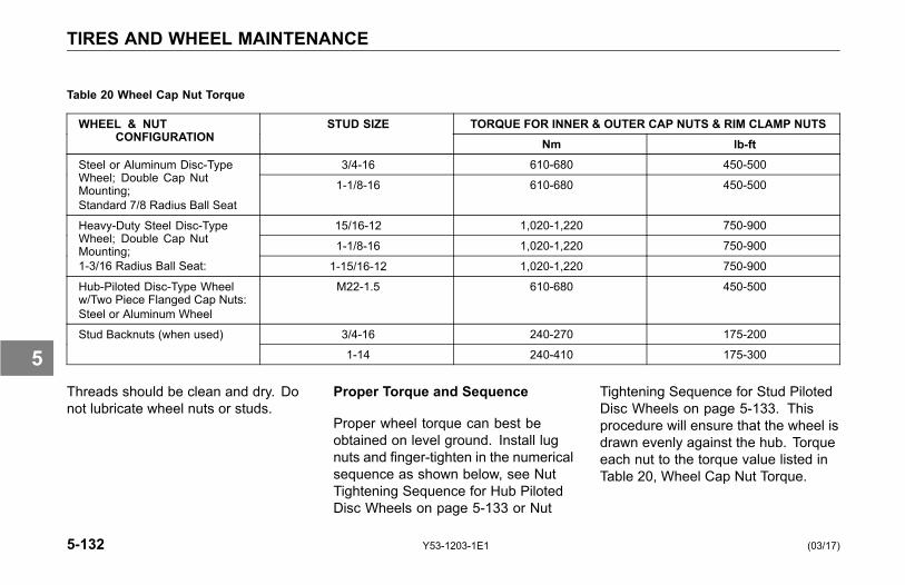
TIRES AND WHEEL MAINTENANCE
Table 20 Wheel Cap Nut Torque
TORQUE FOR INNER & OUTER CAP NUTS & RIM CLAMP NUTSWHEEL & NUTCONFIGURATION
STUD SIZENm lb-ft
3/4-16 610-680 450-500Steel or Aluminum Disc-TypeWheel; Double Cap NutMounting;Standard 7/8 Radius Ball Seat
1-1/8-16 610-680 450-500
15/16-12 1,020-1,220 750-900
1-1/8-16 1,020-1,220 750-900
Heavy-Duty Steel Disc-TypeWheel; Double Cap NutMounting;1-3/16 Radius Ball Seat: 1-15/16-12 1,020-1,220 750-900
Hub-Piloted Disc-Type Wheelw/Two Piece Flanged Cap Nuts:Steel or Aluminum Wheel
M22-1.5 610-680 450-500
3/4-16 240-270 175-200Stud Backnuts (when used)
1-14 240-410 175-300
Threads should be clean and dry. Donot lubricate wheel nuts or studs.
Proper Torque and Sequence
Proper wheel torque can best beobtained on level ground. Install lugnuts and finger-tighten in the numericalsequence as shown below, see NutTightening Sequence for Hub PilotedDisc Wheels on page 5-133 or Nut
Tightening Sequence for Stud PilotedDisc Wheels on page 5-133. Thisprocedure will ensure that the wheel isdrawn evenly against the hub. Torqueeach nut to the torque value listed inTable 20, Wheel Cap Nut Torque.
5-132 Y53-1203-1E1 (03/17)
5
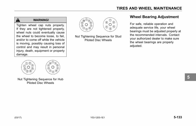
TIRES AND WHEEL MAINTENANCE
WARNING!Tighten wheel cap nuts properly.If they are not tightened properly,wheel nuts could eventually causethe wheel to become loose, to fail,and/or to come off while the vehicleis moving, possibly causing loss ofcontrol and may result in personalinjury, death, equipment or propertydamage.
Nut Tightening Sequence for HubPiloted Disc Wheels
Nut Tightening Sequence for StudPiloted Disc Wheels
Wheel Bearing Adjustment
For safe, reliable operation andadequate service life, your wheelbearings must be adjusted properly atthe recommended intervals. Contactyour authorized dealer to make surethe wheel bearings are properlyadjusted.
(03/17) Y53-1203-1E1 5-133
5
TIRES AND WHEEL MAINTENANCE
Wheel Replacement withDisc Brake Option
Use only the wheel brand, size andpart number originally installed byKenworth. Use of a different wheelbrand or size could cause valve stemto interfere with a brake componentwhich could lead to loss of vehiclecontrol and may lead to personal injury.
Vehicles equipped with front discbrakes are fitted with wheels designedspecifically for disc brake applications.If it ever becomes necessary toreplace an original equipment wheel,the replacement wheel must be thesame brand and size as the take-offwheel. On vehicles equipped with 22.5in. disc wheels, installing the wrongreplacement wheel could result inthe wheel valve stem making contactwith the disc brake assembly. Wheninstalling any replacement wheel,always inspect the tires/wheels to
ensure there is adequate clearancebetween other vehicle components.
With the hood open, check forclearance between the wheel and discbrake assembly. Use a hydraulic jackto raise the front of the vehicle offthe ground to allow the wheel to spinfreely. While rotating the wheel, checkto ensure there is adequate clearancebetween the wheel and disc brakeassembly
WARNING!If the hood falls, anyone under itcould be injured. Always attach thesafety cable and/or hood stop whenthe hood is in its open position anytime anyone gets under the hoodfor any reason. Failure to complymay result in personal injury, death,equipment or property damage.
WARNING!Always support the vehicle with ap-propriate safety stands if it is neces-sary to work underneath the vehicle.A jack is not adequate for this pur-pose. Failure to comply may resultin personal injury, death, equipmentor property damage.
WARNING!Improperly mounting and demount-ing tire and rim assemblies is dan-gerous. Failure to observe properprecautions could cause the tire-rimassembly to burst explosively, caus-ing serious injury or death. See thewheel manufacturer's literature forthe proper way to mount and de-mount your tires and rims. Followtheir precautions exactly. Failure tocomply may result in personal injury,death, equipment or property dam-age.
5-134 Y53-1203-1E1 (03/17)
5
TIRES AND WHEEL MAINTENANCE
Disc Wheels
WARNING!Use the correct components andtools when working on wheels.Grooves in the wheel disc or otherdamage to the disc can weaken thewheel and cause it to eventuallycome off. This could cause you tolose control of your vehicle, andmay result in an accident. Failureto comply may result in personalinjury, death, equipment or propertydamage.
The end of the wheel wrench mustbe smooth. Burrs on the end of thewrench can tear grooves in the disc.These grooves may lead to cracks inthe disc, and can cause it to fail.
Comparing Hub Piloted andBall Seat Parts
WARNING!Do not mismatch wheel compo-nents. Equipment that does not ex-actly match original specifications orthat is mismatched could cause thewheels to break and separate fromthe vehicle. The resulting accidentcould be very serious. Each mount-ing system is engineered for useonly with its correct mating part. Besure properly matched componentsare used for each type of mount-ing. Failure to comply may result inpersonal injury, death, equipment orproperty damage.
The following comparison (Table 21,Comparing Hub-piloted and Ball-seatWheels), shows the differencebetween parts used in hub pilot mountand ball seat mount applications.
(03/17) Y53-1203-1E1 5-135
5
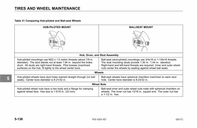
TIRES AND WHEEL MAINTENANCE
Table 21 Comparing Hub-piloted and Ball-seat Wheels
HUB-PILOTED MOUNT BALLSEAT MOUNT
Hub, Drum, and Stud AssemblyHub-piloted mountings use M22 x 1.5 metric threads (about 7/8 in.diameter). The stud stands out at least 1.94 in. beyond the brakedrum. All studs are right-hand threads. Pilot bosses (machinedsurfaces) on the hub, fit tightly to the wheel center bore.
Ball-seat (stud-piloted) mountings use 3/4x16 or 1-1/8x16 threads.The dual mounting studs provide 1.30 in. 1.44 in. standout.Right-hand and left-hand threads are required. Inner and outer wheelnuts center the wheels by seating against wheel ball seats.
WheelsHub-piloted wheels have stud holes reamed straight through (no ballseats). Center bore diameter is 8-21/32 in.
Ball-seat wheels have spherical chamfers machined on each studhole. Center bore diameter is 8-23/32 in.
Wheel NutsHub-piloted wheel nuts have a hex body and a flange for clampingagainst wheel face. Hex size is 1-5/16 in. (33 mm).
Ball-seat inner and outer wheel nuts mate with spherical chamfers onwheels. The inner nut has 13/16 in. square end. The outer nut hasa 1-1/2 in. hex.
5-136 Y53-1203-1E1 (03/17)
5

TIRES AND WHEEL MAINTENANCE
Tire Replacement
Front: Replace front tires when lessthan 4/32 in. of tread remains. Checkat three places equally spaced aroundthe tire.
Drive Axles or Trailers: Replace tireson drive axles or trailers when less than2/32 in. of tread depth remains in anymajor groove. Check at three placesequally spaced around the tire. Seethe next illustration for recommendedmeasuring points for tread depth.
Steer Tire Points (left), Drive TirePoints (right)
WARNING!Do not install regrooved or rein-forcement- repaired tires on steeringaxles. They could fail unexpectedlyand cause you to lose control ofyour vehicle resulting in an accident.Failure to comply may result in per-sonal injury, death, equipment orproperty damage.
WARNING!Do not replace original equipmenttires with load ratings less than theoriginal tires. Doing so could lead tounintentional overloading of the tire,which could cause a failure resultingin loss of vehicle control and an ac-cident. Failure to comply may resultin personal injury, death, equipmentor property damage.
NOTETo prolong the tires' life and makethem safer, have their radial andlateral run-out checked at your Ken-worth Dealer. And of course havethe tires balanced any time youchange a tire.
(03/17) Y53-1203-1E1 5-137
5
TIRES AND WHEEL MAINTENANCE
Matching Tires
Be sure to buy matched tires foryour vehicle, especially on the rearaxles. Mismatched tires can causestress between axles and cause thetemperature of the axle lubricant to gettoo hot. Matched tires will help thedriveline last longer and will give youbetter tire mileage.
WARNING!Do not mismatch tires, it can be dan-gerous. Never mix tires of differ-ent design such as steel belted ra-dials and bias ply tires, etc. Mixingtire types and sizes will adversely af-fect the road-holding ability of bothtypes of tires and can lead to lossof vehicle control. Failure to complymay result in personal injury, death,equipment or property damage.
Make sure, too, that you use the rightsize tires on each wheel. Some trucks
require different sizes on front and rearwheels. For safety, always use therecommended size and type of tires.
Greenhouse Gas Certified Tires
Replacing a tire that is greenhousegas certified.
NOTEThe tires installed on this vehicleat the factory as original equipmentare certified for Greenhouse Gasand Fuel Efficiency regulations. Re-placement tires must be of equal orlower rolling resistance level (TRRLor Crr). Consult with your tire sup-plier(s) for appropriate replacementtires.
Verify if your vehicle is equipped withGreenhouse Gas certified tires bychecking the Vehicle Emission Controllabel on the driver's side door frame. Ifthese tires were installed at the factory,Lower Rolling Resistance codes (LRR)identify which tires are certified.
5-138 Y53-1203-1E1 (03/17)
5
TIRES AND WHEEL MAINTENANCE
Maintaining a greenhouse gascertified tire.
In order to limit the rolling resistance ofthe tires and optimize fuel economy,the maintenance procedures specifiedby the tire manufacture must befollowed.
For warranty information, See OriginalEquipment Tires on page 6-10.
(03/17) Y53-1203-1E1 5-139
5

TRANSMISSION MAINTENANCE
TRANSMISSIONMAINTENANCE
Introduction
See the transmission manufacturer'soperator's manual for lubricationspecifications and service intervals.
5-140 Y53-1203-1E1 (03/17)
5
CLUTCH
CLUTCH
Introduction
Free pedal is the distance the clutchpedal moves by applying only slightpressure. During free pedal therelease yoke in the transmissionmoves until its bearing pads contactthe release bearing. This movement ofthe release yoke is called free travel.Thus, free pedal and free travel aredirectly related to each other.
As the clutch pedal is depressedfurther, with harder pressure, therelease yoke moves the releasebearing away from the engine. Thiscauses the clutch plate to release fromthe driven disks in the clutch. This iscalled release travel. And finally, as thepedal is pushed to the last 1/2 to 1 inchof travel, the release bearing contactsand engages the clutch brake. Thisis called clutch brake squeeze. Whenthe clutch wears, the release bearing
gradually moves toward the engine,decreasing free pedal and free travel.When all free pedal and free travel aregone, the clutch requires adjustment.
The clutch is adjusted by turning anadjustment ring that is built into theclutch. When the ring is turned, therelease bearing moves back towardthe transmission, restoring free pedaland clutch free travel. Under normalclutch wear this is the only adjustmentneeded. Do not attempt to change anyother component.
Clutch Linkage
Have your authorized KenworthDealer service the clutch accordingto the clutch manufacturer's serviceguidelines.
• The Kenworth is equipped with arod and lever mechanical clutchlinkage. Lubricate each pivot pointon the clutch linkage.
(03/17) Y53-1203-1E1 5-141
5
CLUTCH
Clutch Adjustment - NormalWear
See the clutch manufacturer's ServiceManual for the proper adjustmentprocedures.
NOTEThis procedure is all that is requiredfor normal clutch adjustment. Ad-justment of any other components isnot required.
External Linkage Adjustment
1. Adjust clutch to clutchmanufacturer's specification.
2. Verify 1/8 in. free travel (distancethe release yoke moves before therelease yoke bearing pads contactthe release bearing).
3. Verify free pedal of 1.75 in. (44mm ± 6 mm).
5-142 Y53-1203-1E1 (03/17)
5
INFORMATION
CONSUMER INFORMATION AND VEHICLE IDENTIFICATIONIntroduction . . . . . . . . . . . . . . . . . . 6-3Reporting Safety Defects . . . . . . . . . . . . 6-3Vehicle Identification . . . . . . . . . . . . . . 6-4Certification Labels . . . . . . . . . . . . . . . 6-5Component Identification. . . . . . . . . . . . . 6-8How to Order Parts . . . . . . . . . . . . . . . 6-9
VEHICLE EMISSIONS LIMITED EXPRESS WARRANTYOriginal Equipment Tires . . . . . . . . . . . . 6-10Greenhouse Gas (GHG) Components Other ThanTires . . . . . . . . . . . . . . . . . . . 6-11
Your Warranty Rights and Obligations . . . . . . 6-11Manufacturer's Warranty Coverage . . . . . . . 6-12Owner's Warranty Responsibilities . . . . . . . 6-12Replacement Parts . . . . . . . . . . . . . . 6-13PACCAR Responsibilities . . . . . . . . . . . 6-14Warranty Limitations. . . . . . . . . . . . . . 6-14
(03/17) Y53-1203-1E1 6-1
6

CONSUMER INFORMATION AND VEHICLE IDENTIFICATION
CONSUMERINFORMATIONAND VEHICLEIDENTIFICATION
Introduction
WARNING!This vehicle contains materialknown by the State of California tocause cancer and/or birth defectsor other reproductive harm. Thiswarning requirement is mandatedby California law (Proposition 65)and does not result from any changein the manner in which Kenworthtrucks are manufactured.
Reporting Safety Defects
United States
If you believe that your vehicle hasa defect which could cause a crashor could cause injury or death, youshould immediately inform the NationalHighway Traffic Safety Administration(NHTSA) in addition to notifyingKenworth Truck Company.
If NHTSA receives similar complaints,it may open an investigation, andif it finds that a safety defect existsin a group of vehicles, it may ordera recall and remedy campaign.However, NHTSA cannot get involvedin individual problems between you,your Kenworth Dealer, and KenworthTruck Company.
To contact NHTSA, you may eithercall the Auto Safety Hotline toll-freeat 1-800-424-9393 (366-0123 inWashington, D.C.) or write to:
Administrator, NHTSA, 400 SeventhStreet, S.W., Washington, D.C. 20590.You can also get other informationabout auto safety from the Hotline.
Canada
Canadian customers whowish to reporta safety-related defect to TransportCanada, Defect Investigations andRecalls, may telephone the toll freehotline 1-800-333-0510, or contactTransport Canada bymail at: TransportCanada, ASFAD, Place de Ville TowerC, 330 Sparks Street, Ottawa ON K1A0N5.
For additional road safety information,please visit the Road Safety websiteat: www.tc.gc.ca/roadsafety
(03/17) Y53-1203-1E1 6-3
6
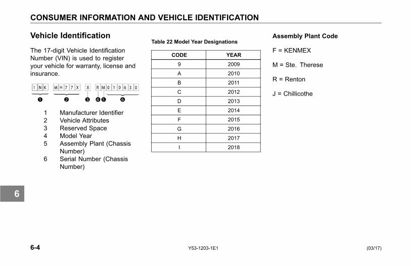
CONSUMER INFORMATION AND VEHICLE IDENTIFICATION
Vehicle Identification
The 17-digit Vehicle IdentificationNumber (VIN) is used to registeryour vehicle for warranty, license andinsurance.
1 Manufacturer Identifier2 Vehicle Attributes3 Reserved Space4 Model Year5 Assembly Plant (Chassis
Number)6 Serial Number (Chassis
Number)
Table 22 Model Year Designations
CODE YEAR9 2009
A 2010
B 2011
C 2012
D 2013
E 2014
F 2015
G 2016
H 2017
I 2018
Assembly Plant Code
F = KENMEX
M = Ste. Therese
R = Renton
J = Chillicothe
6-4 Y53-1203-1E1 (03/17)
6

CONSUMER INFORMATION AND VEHICLE IDENTIFICATION
VIN Location
The full, 17-digit VIN is exclusivelylocated on the Weight Rating DataLabel. The label is located on thedriver's side door edge or on thedriver's side door frame.
Chassis Number
The Chassis Number refers to thelast seven characters of the VIN.This number will allow your KenworthDealer to identify your vehicle. You willbe asked for this number when youbring it in for service.
Chassis Number Locations
• Right frame rail, top flange, about3 ft. from the front end
• Cab back, left-hand rear panel,lower edge
• Tire, Rim, and Weight Rating Datalabel (truck)
• Components and Weights label
• Noise Emission label
• Paint Identification label
Certification Labels
Vehicle information and specificationsfor your Kenworth are documented onlabels. As noted below, each labelcontains specific information pertainingto vehicle capacities and specificationsthat you should be aware of.
(03/17) Y53-1203-1E1 6-5
6

CONSUMER INFORMATION AND VEHICLE IDENTIFICATION
Components and Weights Label
The Components and Chassis WeightLabel is located on either the driver'sside door edge or on the driver'sside door frame. It includes chassisnumber, chassis weight and grossweight, plus model information for thevehicle, engine, transmission, andaxles.
Tire, Rim and Weight Rating DataLabel
The Tire, Rim and Weight RatingData Label is located on the driver'sside door edge or on the driver's sidedoor frame. It contains the followinginformation:
• GVWR - Gross Vehicle WeightRating
• GAWR FRONT, INTERMEDIATEand REAR - Gross Axle WeightRatings for Front, Intermediateand Rear Axle
• TIRE/RIM SIZES AND INFLATIONPRESSURES - Tire/Rim Sizesand Cold Pressure Minimums
• VIN including CHASSIS NUMBER
WARNING!Do not exceed the specified load rat-ing. Overloading can result in lossof vehicle control and personal in-jury, either by causing componentfailures or by affecting vehicle han-dling. Exceeding load ratings canalso shorten the service life of thevehicle. Failure to comply may re-sult in personal injury, death, equip-ment or property damage.
The components of your vehicleare designed to provide satisfactoryservice if the vehicle is not loadedin excess of either the gross vehicleweight rating (GVWR), or the maximumfront and rear gross axle weight ratings(GAWRs).
6-6 Y53-1203-1E1 (03/17)
6
CONSUMER INFORMATION AND VEHICLE IDENTIFICATION
NOTEGVW is the TOTAL SCALEWEIGHTthe vehicle is designed to carry. Thisincludes the weight of the empty ve-hicle, loading platform, occupants,fuel, and any load.
Noise Emission Label
The Noise Emission Label is locatedin the driver's side door frame. Itcontains information regarding U.S.noise emission regulations, chassisnumber, and date of manufacture.
Paint Identification Label
The Paint Identification Label containsthe paint colors used by the factoryto paint your vehicle. It lists frame,wheels, cab interior and exteriorcolors. This label is located inside theglove box.
(03/17) Y53-1203-1E1 6-7
6
CONSUMER INFORMATION AND VEHICLE IDENTIFICATION
Federal Safety StandardCertification Label
The NHTSA regulations require a labelcertifying compliance with FederalSafety Standards, for United Statesand U.S. Territories, be affixed toeach motor vehicle and prescribewhere such label may be located.This certification label, which indicatesthe date of manufacture and otherpertinent information, is located onthe driver's side door edge or on thedriver's side door frame.
Component Identification
Each of the major components onyour vehicle has an identification labelor tag. For easy reference, recordcomponent numbers such as, model,serial, and assembly number.
Engine: For further information,please refer to the Engine Operationand Maintenance Manual.
Transmission: For both manualand automatic transmissions, theidentification number is stamped on atag affixed to the right rear side of thetransmission case.
Clutch: Enclosed in clutch housing.Location depends on manufacturer.
Steer Axle: The front axle serialnumber is stamped on a plate locatedon the center of the axle beam.
Drive Axles: The drive axle numberingsystem includes three labels or stamps:
1. Axle Specification Number, usuallystamped on the right rear side ofthe axle housing. This numberidentifies the complete axle.
2. Axle Housing Number Tag, usuallylocated on the left forward sideof the housing arm. This tagidentifies the axle housing.
3. Axle Differential CarrierIdentification, usually locatedon the top side of the differentialcarrier. The following informationis either stamped, or marked with ametal tag: Model No., ProductionAssembly No., Serial No., GearRatio, and Part Number.
6-8 Y53-1203-1E1 (03/17)
6
CONSUMER INFORMATION AND VEHICLE IDENTIFICATION
How to Order Parts
Replacement parts may be obtainedfrom an authorized dealership.
When you order, it is IMPORTANTthat you have the following informationready:
• Your name and address.
• Serial number of the truck.
• The name of the part you need.
• The name and number of thecomponent for which the part isrequired.
• The quantity of parts you need.
• How you want your order shipped.
(03/17) Y53-1203-1E1 6-9
6
VEHICLE EMISSIONS LIMITED EXPRESS WARRANTY
VEHICLE EMISSIONSLIMITED EXPRESSWARRANTY
Original Equipment Tires
PACCAR Inc warrants the tiresinstalled as original equipment onthis vehicle only against defects inmaterials and workmanship whichcause the vehicle to fail to complywith applicable U.S. and Canadiangreenhouse gas emission limits("Warrantable Emissions Failures").This vehicle emissions limited expresswarranty relating to original equipmenttires is valid for two (2) years or 24,000miles, whichever occurs first.
YOUR SOLE AND EXCLUSIVEREMEDY AGAINST PACCAR IncIS LIMITED TO THE REPAIR ORREPLACEMENT OF ORIGINALEQUIPMENT TIRES, SUBJECT TOPACCAR’S TIME AND MILEAGE
LIMITATIONS LISTED ABOVE. ThisVehicle Emissions Limited ExpressWarranty relating to original equipmenttires begins on the date of delivery ofthe vehicle to the first purchaser orlessee and accrued time andmileage iscalculated when the vehicle is broughtin for correction of the WarrantableEmissions Failures relating to theoriginal equipment tires.
PACCAR MAKES NO OTHERVEHICLE EMISSIONS WARRANTIESRELATING TO THE ORIGINALEQUIPMENT TIRES, EXPRESSOR IMPLIED. WHERE PERMITTEDBY LAW, PACCAR EXPRESSLYDISCLAIMS ANY WARRANTY OFMERCHANTABILITY OR FITNESSFOR A PARTICULAR PURPOSERELATING TO VEHICLE EMISSIONS.PACCAR AND THE SELLINGDEALER SHALL NOT BE LIABLE FORINCIDENTAL OR CONSEQUENTIALDAMAGES INCLUDING, BUT NOTLIMITED TO: LOSS OF INCOME
OR LOST PROFITS; VEHICLEDOWNTIME; COMMUNICATIONEXPENSES; LODGING AND/ORMEAL EXPENSES; FINES;APPLICABLE TAXES OR BUSINESSCOSTS OR LOSSES; ATTORNEY’SFEES; AND ANY LIABILITY YOU MAYHAVE IN RESPECT TO ANY OTHERPERSON OR ENTITY RELATINGTO WARRANTABLE EMISSIONSFAILURES.
This Vehicle Emissions LimitedExpress Warranty relating tooriginal equipment tires is limitedto emissions compliance only.The tires are separately warrantedby their manufacturer for defects inmaterials and workmanship other thanthose which cause non-compliancewith U.S. and Canadian GHGregulations, subject to limitations andconditions contained within the tiremanufacturer’s warranty agreement.You are responsible for the safeoperation and maintenance of the
6-10 Y53-1203-1E1 (03/17)
6
VEHICLE EMISSIONS LIMITED EXPRESS WARRANTY
vehicle and its tires. PACCAR doesnot warrant wear and tear of the tires.
Greenhouse Gas (GHG)Components Other ThanTires
This GHG vehicle Warranty applies tothe vehicle (hereafter, vehicle) certifiedwith the US Environmental ProtectionAgency.
Your Warranty Rights andObligations
This vehicle is warranted forcomponents that directly impact themanufacturers greenhouse gas (GHG)certification with the US EnvironmentalProtection Agency. PACCAR mustwarrant these components for theperiods of time listed below providedthere has been no abuse, neglect orimproper maintenance of the vehicle.
If a GHG-related part on your vehicleis found to have a defect in material orassembly, the part will be repaired orreplaced by PACCAR.
(03/17) Y53-1203-1E1 6-11
6
VEHICLE EMISSIONS LIMITED EXPRESS WARRANTY
Manufacturer's WarrantyCoverage
This warranty coverage is provided forfive years or 100,000 miles (160,000)km, whichever first occurs, from thedate of delivery of the vehicle tothe first purchaser or first lessee.Where a Warrantable Condition exists,PACCAR will diagnose and repairthe vehicle, parts and labor included,at no cost to the first purchaser orfirst lessee and each subsequentpurchaser or lessee. This warrantydoes not override any extendedwarranty purchased to cover specificvehicle components.
Owner's WarrantyResponsibilities
The vehicle owner is responsible forperforming required maintenance thatis listed in your engine and vehicleOperator’s Manuals. The owner isresponsible for presenting the vehicleto a service location as soon as aproblem exists. Any warranty repairsshould be completed in a reasonableamount of time.
Retain all receipts coveringmaintenance on this equipment.PACCAR cannot deny warranty solelyfor the lack of receipts or for thefailure to ensure the performance of allscheduled maintenance.
PACCAR may deny warranty coverageif a vehicle component has failed due toabuse, neglect, improper maintenance,unapproved modifications (bothphysical components and computer
programming) or using non-OriginalEquipment replacement parts.
If there are any questionsregarding these warranty rightsand responsibilities, please contactthe vehicle OEM manufacturer at thecustomer center telephone numberprovided with the vehicle operatinginstructions.
Prior to the expiration of the applicablewarranty, Owner must give notice ofany warranted failure to an authorizedPACCAR dealer and deliver the vehicleto such facility for repair.
Owner is responsible for incidentalcosts such as: communicationexpenses, meals, lodging incurred byOwner or employees of Owner as aresult of a Warrantable Condition.
Owner is responsible for downtimeexpenses, cargo damage, fines, allapplicable taxes, all business costs,
6-12 Y53-1203-1E1 (03/17)
6
VEHICLE EMISSIONS LIMITED EXPRESS WARRANTY
and other losses resulting from aWarrantable Condition.
Owner is responsible for maintainingall emissions related engine andvehicle computer program settingsin accordance with manufacturerspecifications. This responsibilityincludes GHG specific settingsthat may not be altered before theGHG-related expiration mileage hasbeen reached for each system.
Owner is responsible for maintainingall physical parts related toGHG-regulations in the as-builtconfiguration and in proper workingorder for the full regulatory useful lifeof 435,000 miles for Class 8 vehicles,185,000 miles for Class 6-7, and110,000 for Class 5.
Replacement Parts
PACCAR recommends that anyservice parts used for maintenance,repair or replacement of GHGcomponents be new or genuineapproved rebuilt parts and assemblies.The use of non-genuine engine orvehicle replacement parts that are notequivalent to the PACCAR engine orOEM vehicle manufacturer’s originalpart specification as built from thefactory may impair the engine andvehicle emissions control system fromworking or functioning effectively, andmay jeopardize your GHG warrantycoverage.
In addition, genuine vehicle or engineparts must be replaced with the samematerial and function as the partassembled on the vehicle from thefactory.
The owner may elect to havemaintenance, replacement or repair of
the emission control parts performedby a facility other than an authorizedPACCAR dealer and may elect touse parts other than new or genuineapproved rebuilt parts and assembliesfor such maintenance, replacementor repair; however, the cost of suchservice or parts and subsequentfailures resulting from such serviceor parts may not be fully warrantedif the manufacturer determines thatthe replacement part is not of similarmaterial and function as the OEM partassembled to the vehicle at the factory.
(03/17) Y53-1203-1E1 6-13
6
VEHICLE EMISSIONS LIMITED EXPRESS WARRANTY
PACCAR Responsibilities
The warranty coverage begins whenthe vehicle is delivered to the firstpurchaser or first lessee. Repairsand service will be performed by anyauthorized PACCAR dealer usingnew or genuine approved rebuilt partsand assemblies PACCAR will utilizereplacement parts that are selectedand installed to support the GHGcompliance certification. PACCARwill repair parts found by PACCAR tobe defective without charge for partsor labor (including diagnosis whichresults in determination that there hasbeen a failure of a warranted part).
Warranty Limitations
Sole and exclusive remedy againstPACCAR and the Selling Dealerarising from the purchase and useof this vehicle is limited to the repairor replacement of "warrantablefailures", for replacement parts thatare similar in material and functionto OEM specifications and subject toPACCAR’s time, mileage, and hourlimitations of the greenhouse gaswarranty. The maximum time, mileageand hour limitations of the warrantybegin with the Date of Delivery to thefirst purchaser or first lessee. Theaccrued time, mileage, or hours iscalculated when the vehicle is broughtin for correction of warrantable failures.
PACCAR is not responsible forfailures or damage resulting from whatPACCAR determines to be abuse,neglect or uncontrollable acts of nature,including, but not limited to: damagedue to accident; operation without
adequate coolants or lubricants;overfueling; overspeeding; lack ofmaintenance of cooling, lubricatingor intake systems; improper storage,starting, warm-up, run-in or shutdownpractices; unauthorized modificationsto the vehicle and its components.PACCAR is also not responsible forfailures caused by incorrect oil, fuelor diesel exhaust fluid or by water,dirt or other contaminants in the fuel,oil or diesel exhaust fluid. Failureof replacement parts used in repairsdue to the above non-warrantableconditions is not warrantable.
This warranty is void if the vehicle isaltered with parts that do not meet thematerial and functional specificationsas manufactured from the factory.Any alterations to vehicle or enginecomputer settings will void GHGwarranty and potentially cause thevehicle to become non-compliantwith the GHG regulation of the EPAClean Air Act. Any alterations to
6-14 Y53-1203-1E1 (03/17)
6
VEHICLE EMISSIONS LIMITED EXPRESS WARRANTY
GHG specific settings prior to theGHG related expiration mileage foreach system will void GHG warrantyand potentially cause the vehicleto become non-compliant with theGHG regulation of the EPA Clean AirAct. This warranty is void if certainGHG components are not properlymaintained and thus cannot perform totheir designed capability.
PACCAR is not responsible for failuresresulting from improper repair or theuse of parts which are not genuineapproved parts.
PACCAR is not responsible for thematerial and labor costs of emissioncontrol parts and assemblies replacedduring Scheduled Maintenance ofthe engine as specified in PACCAROperator’s Manuals.
THIS WARRANTY, TOGETHERWITH THE EXPRESS COMMERCIALWARRANTIES ARE THE SOLE
WARRANTIES MADE BY PACCAR INREGARD TO THIS VEHICLE.
THIS LIMITED GHG WARRANTYIS THE SOLE WARRANTY MADEBY PACCAR AND THE SELLINGDEALER. EXCEPT FOR THE ABOVELIMITED WARRANTY, PACCAR ANDTHE SELLING DEALER MAKE NOOTHER WARRANTIES, EXPRESSOR IMPLIED. PACCAR AND THESELLING DEALER EXPRESSLYDISCLAIM ANY WARRANTY OFMERCHANTABILITY OR WARRANTYOF FITNESS FOR A PARTICULARPURPOSE.
PACCAR AND THE SELLINGDEALER SHALL NOT BE LIABLE FORINCIDENTAL OR CONSEQUENTIALDAMAGES INCLUDING, BUT NOTLIMITED TO: LOSS OF INCOMEOR LOST PROFITS; ENGINE ORVEHICLE DOWNTIME; THIRD PARTYDAMAGE, INCLUDING DAMAGEOR LOSS TO OTHER ENGINES,
VEHICLES OR PROPERTY,ATTACHMENTS, TRAILERS ANDCARGO; LOSS OR DAMAGETO PERSONAL CONTENTS;COMMUNICATION EXPENSES;LODGING AND/OR MEALEXPENSES; FINES; APPLICABLETAXES OR BUSINESS COSTS ORLOSSES; ATTORNEYS’ FEES; ANDANY LIABILITY YOU MAY HAVE INRESPECT TO ANY OTHER PERSONOR ENTITY.
(03/17) Y53-1203-1E1 6-15
6

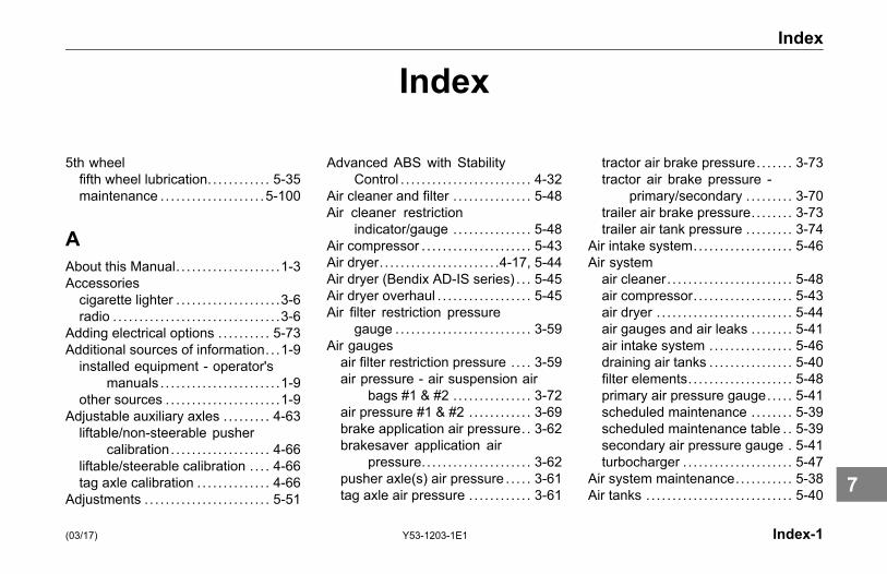
Index
Index
5th wheelfifth wheel lubrication. . . . . . . . . . . . 5-35maintenance . . . . . . . . . . . . . . . . . . . .5-100
AAbout this Manual. . . . . . . . . . . . . . . . . . . .1-3Accessoriescigarette lighter . . . . . . . . . . . . . . . . . . . .3-6radio . . . . . . . . . . . . . . . . . . . . . . . . . . . . . . . .3-6
Adding electrical options . . . . . . . . . . 5-73Additional sources of information. . .1-9installed equipment - operator's
manuals . . . . . . . . . . . . . . . . . . . . . . .1-9other sources . . . . . . . . . . . . . . . . . . . . . .1-9
Adjustable auxiliary axles . . . . . . . . . 4-63liftable/non-steerable pusher
calibration. . . . . . . . . . . . . . . . . . . 4-66liftable/steerable calibration . . . . 4-66tag axle calibration . . . . . . . . . . . . . . 4-66
Adjustments . . . . . . . . . . . . . . . . . . . . . . . . 5-51
Advanced ABS with StabilityControl . . . . . . . . . . . . . . . . . . . . . . . . . 4-32
Air cleaner and filter . . . . . . . . . . . . . . . 5-48Air cleaner restriction
indicator/gauge . . . . . . . . . . . . . . . 5-48Air compressor . . . . . . . . . . . . . . . . . . . . . 5-43Air dryer. . . . . . . . . . . . . . . . . . . . . . .4-17, 5-44Air dryer (Bendix AD-IS series) . . . 5-45Air dryer overhaul . . . . . . . . . . . . . . . . . . 5-45Air filter restriction pressure
gauge . . . . . . . . . . . . . . . . . . . . . . . . . . 3-59Air gaugesair filter restriction pressure . . . . 3-59air pressure - air suspension air
bags #1 & #2 . . . . . . . . . . . . . . . 3-72air pressure #1 & #2 . . . . . . . . . . . . 3-69brake application air pressure. . 3-62brakesaver application air
pressure. . . . . . . . . . . . . . . . . . . . . 3-62pusher axle(s) air pressure . . . . . 3-61tag axle air pressure . . . . . . . . . . . . 3-61
tractor air brake pressure. . . . . . . 3-73tractor air brake pressure -
primary/secondary . . . . . . . . . 3-70trailer air brake pressure. . . . . . . . 3-73trailer air tank pressure . . . . . . . . . 3-74
Air intake system.. . . . . . . . . . . . . . . . . . 5-46Air systemair cleaner. . . . . . . . . . . . . . . . . . . . . . . . 5-48air compressor. . . . . . . . . . . . . . . . . . . 5-43air dryer . . . . . . . . . . . . . . . . . . . . . . . . . . 5-44air gauges and air leaks . . . . . . . . 5-41air intake system .. . . . . . . . . . . . . . . 5-46draining air tanks . . . . . . . . . . . . . . . . 5-40filter elements. . . . . . . . . . . . . . . . . . . . 5-48primary air pressure gauge. . . . . 5-41scheduled maintenance . . . . . . . . 5-39scheduled maintenance table . . 5-39secondary air pressure gauge . 5-41turbocharger . . . . . . . . . . . . . . . . . . . . . 5-47
Air system maintenance. . . . . . . . . . . 5-38Air tanks . . . . . . . . . . . . . . . . . . . . . . . . . . . . 5-40
(03/17) Y53-1203-1E1 Index-1
7

Index
Alarms . . . . . . . . . . . . . . . . . . . . . . . . . . . . . . 3-80engine oil pressure . . . . . . . . . . . . . . 3-26fifth wheel slide . . . . . . . . . . . . . . . . . . 3-27low air warning alarm - primary 3-26low air warning alarm -
secondary. . . . . . . . . . . . . . . . . . . 3-26low coolant level. . . . . . . . . . . . . . . . . 3-27park brake. . . . . . . . . . . . . . . . . . . . . . . . 3-26power on self test (POST) . . . . . . 3-27stop engine alarm .. . . . . . . . . . . . . . 3-25
Alert screensalarm clock active . . . . . . . . . . . . . . . 3-83circuit failure . . . . . . . . . . . . . . . . . . . . . 3-83cruise control . . . . . . . . . . . . . . . . . . . . 3-83cruise control rationality . . . . . . . . 3-81DEF.. . . . . . . . . . . . . . . . . . . . . . . . . . . . . . 3-82disabled alert . . . . . . . . . . . . . . . . . . . . 3-87engine over-speed shutdown low air
warning. . . . . . . . . . . . . . . . . . . . . . 3-84engine protection shutdown
timer . . . . . . . . . . . . . . . . . . . . . . . . . 3-84fault alert . . . . . . . . . . . . . . . . . . . . . . . . . 3-86front drive axle speed warning . 3-84hydrocarbon burn . . . . . . . . . . . . . . . 3-83impact alert . . . . . . . . . . . . . . . . . . . . . . 3-86lamp faults . . . . . . . . . . . . . . . . . . . . . . . 3-81
level 1 following distance alert . 3-86level 2 following distance alert . 3-85level 3 following distance alert . 3-85low voltage disconnect. . . . . . . . . . 3-82no-idle shutdown .. . . . . . . . . . . . . . . 3-81not available alert . . . . . . . . . . . . . . . 3-87over-crank protection . . . . . . . . . . . 3-82park brake on while moving . . . . 3-81SCR/DEF .. . . . . . . . . . . . . . . . . . . . . . . 3-82stationary object alert . . . . . . . . . . . 3-86trailer detect. . . . . . . . . . . . . . . . . . . . . . 3-82water in fuel (WIF). . . . . . . . . . . . . . . 3-83Wingman® ACB alert screens . 3-85
Ammeter . . . . . . . . . . . . . . . . . . . . . . . . . . . . 3-59Anti-lock brakes . . . . . . . . . . . . . . . . . . . . 4-29trailer ABS (without PLC) . . . . . . . 4-32trailer ABS power line
communication . . . . . . . . . . . . . 4-31Appliances. . . . . . . . . . . . . . . . . . . . . . . . . . 3-11Audible alerts. . . . . . . . . . . . . . . . . . . . . . . 3-22Automatic Traction Control. .4-29, 4-35Automatic transmissionsauxiliary transmission . . . . . . . . . . . 4-77operation . . . . . . . . . . . . . . . . . . . . . . . . . 4-76
Auxiliary axles . . . . . . . . . . . . . . . . . . . . . . 4-63Axle
Steerable Drive Axle . . . . . . . . . . . . 4-77
BBatteriesbattery access . . . . . . . . . . . . . . . . . . . 5-78battery care . . . . . . . . . . . . . . . . . . . . . . 5-81battery charging . . . . . . . . . . . . . . . . . 5-81jump starting vehicles . . . . . . . . . . . . .2-9remote keyless entry (RKE)
system .. . . . . . . . . . . . . . . . . . . . . 1-15removing and installing
batteries. . . . . . . . . . . . . . . . . . . . . 5-80Bendix Wingman® Active Cruise with
Braking (ACB). . . . . . . . . . . . . . . . . 3-76Brake air pressure gauge . . . . . . . . . 3-62Brake gaugesbrake pedal or trailer brake hand
valve pressure. . . . . . . . . . . . . . 3-62brakesaver application air
pressure. . . . . . . . . . . . . . . . . . . . . 3-62tractor air brake pressure. . . . . . . 3-73tractor primary/secondary air brake
pressure. . . . . . . . . . . . . . . . . . . . . 3-70trailer air brake pressure. . . . . . . . 3-73trailer air tank pressure . . . . . . . . . 3-74
Index-2 Y53-1203-1E1 (03/17)
7
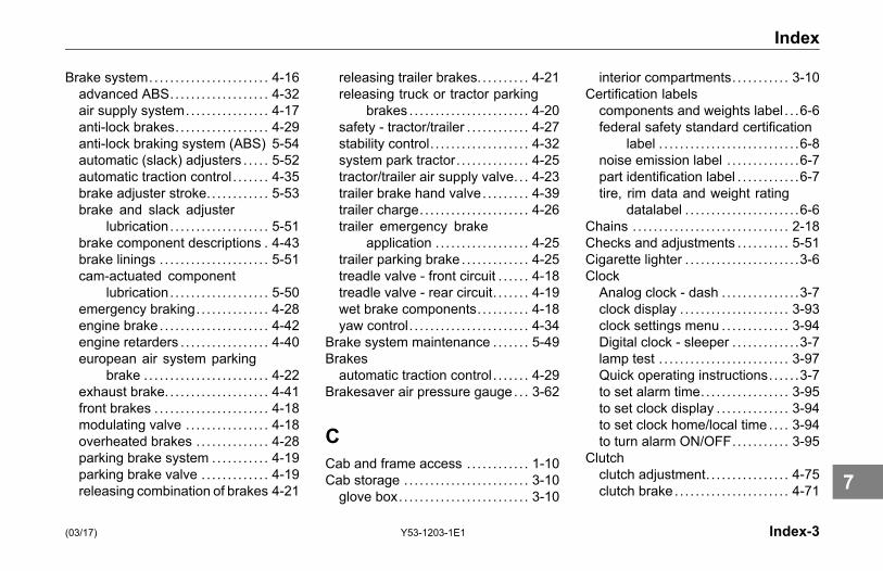
Index
Brake system.. . . . . . . . . . . . . . . . . . . . . . 4-16advanced ABS.. . . . . . . . . . . . . . . . . . 4-32air supply system.. . . . . . . . . . . . . . . 4-17anti-lock brakes. . . . . . . . . . . . . . . . . . 4-29anti-lock braking system (ABS) 5-54automatic (slack) adjusters . . . . . 5-52automatic traction control . . . . . . . 4-35brake adjuster stroke. . . . . . . . . . . . 5-53brake and slack adjuster
lubrication. . . . . . . . . . . . . . . . . . . 5-51brake component descriptions . 4-43brake linings . . . . . . . . . . . . . . . . . . . . . 5-51cam-actuated component
lubrication. . . . . . . . . . . . . . . . . . . 5-50emergency braking. . . . . . . . . . . . . . 4-28engine brake. . . . . . . . . . . . . . . . . . . . . 4-42engine retarders . . . . . . . . . . . . . . . . . 4-40european air system parking
brake . . . . . . . . . . . . . . . . . . . . . . . . 4-22exhaust brake. . . . . . . . . . . . . . . . . . . . 4-41front brakes . . . . . . . . . . . . . . . . . . . . . . 4-18modulating valve . . . . . . . . . . . . . . . . 4-18overheated brakes . . . . . . . . . . . . . . 4-28parking brake system .. . . . . . . . . . 4-19parking brake valve . . . . . . . . . . . . . 4-19releasing combination of brakes 4-21
releasing trailer brakes. . . . . . . . . . 4-21releasing truck or tractor parking
brakes . . . . . . . . . . . . . . . . . . . . . . . 4-20safety - tractor/trailer . . . . . . . . . . . . 4-27stability control. . . . . . . . . . . . . . . . . . . 4-32system park tractor. . . . . . . . . . . . . . 4-25tractor/trailer air supply valve. . . 4-23trailer brake hand valve. . . . . . . . . 4-39trailer charge. . . . . . . . . . . . . . . . . . . . . 4-26trailer emergency brake
application . . . . . . . . . . . . . . . . . . 4-25trailer parking brake . . . . . . . . . . . . . 4-25treadle valve - front circuit . . . . . . 4-18treadle valve - rear circuit. . . . . . . 4-19wet brake components. . . . . . . . . . 4-18yaw control. . . . . . . . . . . . . . . . . . . . . . . 4-34
Brake system maintenance . . . . . . . 5-49Brakesautomatic traction control . . . . . . . 4-29
Brakesaver air pressure gauge . . . 3-62
CCab and frame access . . . . . . . . . . . . 1-10Cab storage . . . . . . . . . . . . . . . . . . . . . . . . 3-10glove box. . . . . . . . . . . . . . . . . . . . . . . . . 3-10
interior compartments. . . . . . . . . . . 3-10Certification labelscomponents and weights label . . .6-6federal safety standard certification
label . . . . . . . . . . . . . . . . . . . . . . . . . . .6-8noise emission label . . . . . . . . . . . . . .6-7part identification label . . . . . . . . . . . .6-7tire, rim data and weight rating
datalabel . . . . . . . . . . . . . . . . . . . . . .6-6Chains . . . . . . . . . . . . . . . . . . . . . . . . . . . . . . 2-18Checks and adjustments . . . . . . . . . . 5-51Cigarette lighter . . . . . . . . . . . . . . . . . . . . . .3-6ClockAnalog clock - dash . . . . . . . . . . . . . . .3-7clock display . . . . . . . . . . . . . . . . . . . . . 3-93clock settings menu .. . . . . . . . . . . . 3-94Digital clock - sleeper . . . . . . . . . . . . .3-7lamp test . . . . . . . . . . . . . . . . . . . . . . . . . 3-97Quick operating instructions. . . . . .3-7to set alarm time.. . . . . . . . . . . . . . . . 3-95to set clock display . . . . . . . . . . . . . . 3-94to set clock home/local time . . . . 3-94to turn alarm ON/OFF.. . . . . . . . . . 3-95
Clutchclutch adjustment. . . . . . . . . . . . . . . . 4-75clutch brake . . . . . . . . . . . . . . . . . . . . . . 4-71
(03/17) Y53-1203-1E1 Index-3
7
Index
clutch linkage . . . . . . . . . . . . . . . . . . .5-141clutch linkage adjustment. . . . . .5-142clutch linkage lubrication
(non-ESI). . . . . . . . . . . . . . . . . . . . 5-35clutch pedal shaft lubrication . . . 5-35clutch release bearing
lubrication. . . . . . . . . . . . . . . . . . . 5-36clutch ring adjustment. . . . . . . . . .5-141clutch travel . . . . . . . . . . . . . . . . . . . . . . 4-71double clutching . . . . . . . . . . . . . . . . . 4-74identification . . . . . . . . . . . . . . . . . . . . . . .6-8riding the clutch. . . . . . . . . . . . . . . . . . 4-74
Clutch maintenance . . . . . . . . . . . . . .5-141Component identification reference 6-8Consumer information . . . . . . . . . . . . . . .6-3how to order parts . . . . . . . . . . . . . . . . .6-9reporting safety defects. . . . . . . . . . .6-3
Controls . . . . . . . . . . . . . . . . . . . . . . . . . . . . . . .3-6indicators. . . . . . . . . . . . . . . . . . . . . . . . . 3-28
Cooling systemadding coolant . . . . . . . . . . . . . . . . . . . 5-67additives. . . . . . . . . . . . . . . . . . . . . . . . . . 5-68coolant change and refilling . . . . 5-69engine (block) heater . . . . . . . . . . . 5-70fan . . . . . . . . . . . . . . . . . . . . . . . . . . . . . . . . 5-96fan clutch. . . . . . . . . . . . . . . . . . . . . . . . . 5-96
radiator cap . . . . . . . . . . . . . . . . . . . . . . 5-70topping up. . . . . . . . . . . . . . . . . . . . . . . . 5-65
Cruise control . . . . . . . . . . . . . . . . . . . . . . 4-11
DDaily checks . . . . . . . . . . . . . . . . . . . . . . . . 1-36Data recorder. . . . . . . . . . . . . . . . . . . . . . . . .1-7Daytime running light (DRL) . . . . . 3-111Differential lock (driver controlled) 4-60Displays/menu screensclock display . . . . . . . . . . . . . . . . . . . . . 3-93clock home/local time . . . . . . . . . . . 3-94clock settings menu .. . . . . . . . . . . . 3-94diagnostic display . . . . . . . . . . . . . . . 3-92fuel economy .. . . . . . . . . . . . . . . . . . . 3-90ignition timer . . . . . . . . . . . . . . . . . . . . . 3-90lamp test . . . . . . . . . . . . . . . . . . . . . . . . . 3-97left hand menu bar . . . . . . . . . . . . . . 3-89multi-function display. . . . . . . . . . . . 3-87multi-function menu items .. . . . . 3-88outside air temperature display 3-58RPM detail . . . . . . . . . . . . . . . . . . . . . . . 3-90speed control management
display. . . . . . . . . . . . . . . . . . . . . . . 3-93to set language . . . . . . . . . . . . . . . . . . 3-97
to set standard or metric units. . 3-97transmission display . . . . . . . . . . . . 3-93trip information. . . . . . . . . . . . . . . . . . . 3-91trip meter . . . . . . . . . . . . . . . . . . . . . . . . . 3-56truck information. . . . . . . . . . . . . . . . . 3-92
Door lock . . . . . . . . . . . . . . . . . . . . . . . . . . . 1-14key fob synchronization. . . . . . . . . 1-16key fob troubleshooting . . . . . . . . . 5-84remote keyless entry (RKE)
system .. . . . . . . . . . . . . . . . . . . . . 1-14Drive axle(s) oil temperature
gauge . . . . . . . . . . . . . . . . . . . . . . . . . . 3-60Drive axlesidentification . . . . . . . . . . . . . . . . . . . . . . .6-8
Driver controlled main differentiallock. . . . . . . . . . . . . . . . . . . . . . . . . . . . . 4-60
Driver'scheck list . . . . . . . . . . . . . . . . . . . . . . . . . 1-35daily checks. . . . . . . . . . . . . . . . . . . . . . 1-36weekly checks . . . . . . . . . . . . . . . . . . . 1-39
Driving tips. . . . . . . . . . . . . . . . . . . . . . . . . . . .4-5coasting . . . . . . . . . . . . . . . . . . . . . . . . . . . .4-5descending a grade . . . . . . . . . . . . . . .4-6economy .. . . . . . . . . . . . . . . . . . . . . . . . . .4-6engine RPM.. . . . . . . . . . . . . . . . . . . . . . .4-6using the tachometer. . . . . . . . . . . . . .4-7
Index-4 Y53-1203-1E1 (03/17)
7
Index
Dual range (two-speed) rear axle 4-61
EElectrical and alternator
precautions. . . . . . . . . . . . . . . . . . . . 5-83Electrical gaugesammeter. . . . . . . . . . . . . . . . . . . . . . . . . . 3-59voltmeter . . . . . . . . . . . . . . . . . . . . . . . . . 3-75
Electrical systemadding electrical options . . . . . . . . 5-73batteries . . . . . . . . . . . . . . . . . . . . . . . . . . 5-78battery care . . . . . . . . . . . . . . . . . . . . . . 5-81battery charging . . . . . . . . . . . . . . . . . 5-81electrical and alternator
precautions . . . . . . . . . . . . . . . . . 5-83fuses, circuit breakers, and
relays. . . . . . . . . . . . . . . . . . . . . . . . 5-71jump starting vehicles . . . . . . . . . . . . .2-9removing and installing
batteries. . . . . . . . . . . . . . . . . . . . . 5-80Electrical system maintenance . . . 5-71Electronic Stability Control
Indicator . . . . . . . . . . . . . . . . . . . . . . . 3-38Emergencybattery connections . . . . . . . . . . . . . 2-11
emergency equipment kit . . . . . . . 1-35jump starting vehicles . . . . . . . . . . . . .2-9
Enginedrive belts . . . . . . . . . . . . . . . . . . . . . . . . 5-96engine fan. . . . . . . . . . . . . . . . . . . . . . . . 5-96engine mounting. . . . . . . . . . . . . . . . . 5-97exhaust system.. . . . . . . . . . . . . . . . . 5-97fuel filters. . . . . . . . . . . . . . . . . . . . . . . . . 5-94identification . . . . . . . . . . . . . . . . . . . . . . .6-8lubrication . . . . . . . . . . . . . . . . . . . . . . . . 5-91pipe and hose clamp torque
values . . . . . . . . . . . . . . . . . . . . . . . 5-93Engine (block) heater. . . . . . . . . . . . . . 5-70Engine block heater . . . . . . . . . . . . . . . 4-47Engine lubrication. . . . . . . . . . . . . . . . . . 5-91Engine maintenance. . . . . . . . . . . . . . . 5-90Engine Mounting . . . . . . . . . . . . . . . . . . . 5-97Engine operation. . . . . . . . . . . . . . . . . . . 4-45cruise control . . . . . . . . . . . . . . . . . . . . 4-52engine block heater . . . . . . . . . . . . . 4-47engine control display. . . . . . . . . . . 4-55engine fan control . . . . . . . . . . . . . . . 4-54engine shutdown system .. . . . . . 4-55shut-down .. . . . . . . . . . . . . . . . . . . . . . . 4-78starting procedure - cold
weather . . . . . . . . . . . . . . . . . . . . . 4-47
starting procedure - normaltemperature. . . . . . . . . . . . . . . . . 4-46
Engine retarders . . . . . . . . . . . . . . . . . . . 4-40Engine temperature gaugeengine (overheating) . . . . . . . . . . . . 3-64
Engine warm-up. . . . . . . . . . . . . . . . . . . . 4-48Environmental Protection . . . . . . . . . . .1-6Ether metering equipment . . . . . . . . 4-51European Air System Parking
Brake . . . . . . . . . . . . . . . . . . . . . . . . . . 4-22Exhaust temperature gaugeengine exhaust gas temperature
(pyrometer) . . . . . . . . . . . . . . . . . 3-67
FFan clutch . . . . . . . . . . . . . . . . . . . . . . . . . . 5-96Fifth wheel . . . . . . . . . . . . . . . . . . . . . . . . . . 4-14air-controlled sliding. . . . . . . . . . . . . 4-14fifth wheel lubrication. . . . . . . . . . . . 5-35jaw lock. . . . . . . . . . . . . . . . . . . . . . . . . . . 4-14maintenance . . . . . . . . . . . . . . . . . . . .5-100
Frame fastener torquerequirements . . . . . . . . . . . . . . . . .5-100
Freeing the vehicle from sand, mud,snow and ice . . . . . . . . . . . .2-17, 2-18
(03/17) Y53-1203-1E1 Index-5
7
Index
Front axle and suspensionmaintenance . . . . . . . . . . . . . . . . .5-102
Fuel economydriving habits. . . . . . . . . . . . . . . . . . . . . . .4-8fuel consumption . . . . . . . . . . . . . . . . . .4-8
Fuel filtersdraining. . . . . . . . . . . . . . . . . . . . . . . . . . . 5-95installing. . . . . . . . . . . . . . . . . . . . . . . . . . 5-94
Fuel gaugesfuel filter restriction pressure . . . 3-67fuel tank(s) level . . . . . . . . . . . . . . . . . 3-68
Fuel shut-off valve . . . . . . . . . . . . . . . . . 4-80Fuel specification . . . . . . . . . . . . . . . . . . 4-80Fuses, circuit breakers and relays 5-71
GGauge panelA - Panel . . . . . . . . . . . . . . . . . . . . . . . . . 3-22
Gauge symbolsair brake application pressure. . 3-53air filter restriction pressure . . . . 3-53ammeter. . . . . . . . . . . . . . . . . . . . . . . . . . 3-53auxiliary transmission oil
temperature. . . . . . . . . . . . . . . . . 3-56
brakesaver air brake applicationpressure. . . . . . . . . . . . . . . . . . . . . 3-54
brakesaver oil temperature . . . . . 3-54diesel exhaust fluid (DEF) . . . . . . 3-54drive axle(s) oil temperature. . . . 3-53engine coolant temperature . . . . 3-54engine exhaust temperature
(pyrometer) . . . . . . . . . . . . . . . . . 3-54engine oil pressure . . . . . . . . . . . . . . 3-54engine oil temperature . . . . . . . . . . 3-54fuel filter restriction pressure . . . 3-54fuel level (primary and
secondary) . . . . . . . . . . . . . . . . . . 3-54general air pressure #1 & #2 . . . 3-54general oil temperature . . . . . . . . . 3-55main transmission oil
temperature. . . . . . . . . . . . . . . . . 3-55manifold boost pressure . . . . . . . . 3-55primary and secondary air
pressure. . . . . . . . . . . . . . . . . . . . . 3-55pusher axles #1, #2 & #3 air
pressure. . . . . . . . . . . . . . . . . . . . . 3-53suspension load air pressure, #1 &
#2. . . . . . . . . . . . . . . . . . . . . . . . . . . . 3-55symbols table . . . . . . . . . . . . . .3-52, 3-53tag axle air pressure . . . . . . . . . . . . 3-53
tractor brake application airpressure. . . . . . . . . . . . . . . . . . . . . 3-55
trailer air tank pressure . . . . . . . . . 3-55trailer brake application air
pressure. . . . . . . . . . . . . . . . . . . . . 3-55transfer case oil temperature. . . 3-55transmission retarder oil
temperature. . . . . . . . . . . . . . . . . 3-56voltmeter . . . . . . . . . . . . . . . . . . . . . . . . . 3-56
Gaugesair filter restriction pressure . . . . 3-59air pressure - primary . . . . . . . . . . . 3-70air pressure - secondary. . . . . . . . 3-70ammeter. . . . . . . . . . . . . . . . . . . . . . . . . . 3-59auxiliary transmission oil
temperature. . . . . . . . . . . . . . . . . 3-75brake application air pressure. . 3-62brakesaver application air
pressure. . . . . . . . . . . . . . . . . . . . . 3-62brakesaver oil temperature . . . . . 3-62diesel exhaust fluid (DEF) . . . . . . 3-63drive axle(s) oil temperature. . . . 3-60engine coolant (water)
temperature. . . . . . . . . . . . . . . . . 3-63engine hour meter. . . . . . . . . . . . . . . 3-58engine oil pressure . . . . . . . . . . . . . . 3-65
Index-6 Y53-1203-1E1 (03/17)
7
Index
engine oil temperature . . . . . . . . . . 3-66engine pyrometer. . . . . . . . . . . . . . . . 3-67fuel filter restriction pressure . . . 3-67fuel tank(s) level . . . . . . . . . . . . . . . . . 3-68general air pressure #1 . . . . . . . . . 3-69general air pressure #2 . . . . . . . . . 3-69general oil temperature . . . . . . . . . 3-70main transmission oil
temperature. . . . . . . . . . . . . . . . . 3-74manifold pressure (turbo boost) 3-70odometer . . . . . . . . . . . . . . . . . . . . . . . . . 3-56primary air pressure. . . . . . . . . . . . . 5-41pusher axle(s) air pressure . . . . . 3-61secondary air pressure . . . . . . . . . 5-41speedometer. . . . . . . . . . . . . . . . . . . . . 3-56suspension load air pressure
#1. . . . . . . . . . . . . . . . . . . . . . . . . . . . 3-72suspension load air pressure
#2. . . . . . . . . . . . . . . . . . . . . . . . . . . . 3-72tachometer . . . . . . . . . . . . . . . . . . 4-7, 3-57tag axle air pressure . . . . . . . . . . . . 3-61tractor brake application air
pressure. . . . . . . . . . . . . . . . . . . . . 3-73trailer air tank air pressure. . . . . . 3-74trailer brake application air
pressure. . . . . . . . . . . . . . . . . . . . . 3-73
transfer case oil temperature. . . 3-74transmission retarder oil
temperature. . . . . . . . . . . . . . . . . 3-75transmission temperature . . . . . . 4-76voltmeter . . . . . . . . . . . . . . . . . . . . . . . . . 3-75
GAWR - Gross Axle WeightRating. . . . . . . . . . . . . . . . . . . . . . . . . . 1-34
GCW - Gross CombinationWeight . . . . . . . . . . . . . . . . . . . . . . . . . 1-34
Glove box. . . . . . . . . . . . . . . . . . . . . . . . . . . 3-10Greenhouse Gas (GHG) Components
Other Than Tires. . . . . . . . . . . . . . 6-11Greenhouse Gas Certification . . . . . .1-8Greenhouse gas certified tires. . .5-138GVWR - Gross Vehicle Weight
Rating. . . . . . . . . . . . . . . . . . . . . . . . . . 1-34
HHeadlampshalogen/hid lamp servicing . . . . . 5-84
Headlamps with Wipersto activate headlamps with
wipers . . . . . . . . . . . . . . . . . . . . . . . 3-96Headlight switch. . . . . . . . . . . . . . . . . . . 3-113Heater and air conditioner . . . . . . .5-105
air conditioner. . . . . . . . . . . . . . . . . . .5-107heater . . . . . . . . . . . . . . . . . . . . . . . . . . .5-106
Heater and air conditionermaintenance . . . . . . . . . . . . . . . . .5-105
Heating and air conditioningair flow control dial . . . . . . . . . . . . . . 3-17cab controls . . . . . . . . . . . . . . . . . . . . . . 3-16cooling. . . . . . . . . . . . . . . . . . . . . . . . . . . . 3-18dash and floor vents . . . . . . . . . . . . 3-17dash vents . . . . . . . . . . . . . . . . . . . . . . . 3-17defrost vents . . . . . . . . . . . . . . . . . . . . . 3-17dehumidify . . . . . . . . . . . . . . . . . . . . . . . 3-18fan control dial . . . . . . . . . . . . . . . . . . . 3-17floor and defrost vents . . . . . . . . . . 3-17floor vents . . . . . . . . . . . . . . . . . . . . . . . . 3-17fresh air mode . . . . . . . . . . . . . . . . . . . 3-17fresh air/recirculation switch. . . . 3-17heating . . . . . . . . . . . . . . . . . . . . . . . . . . . 3-18precautions . . . . . . . . . . . . . . . . . . . . . . 3-13recirculation switch . . . . . . . . . . . . . . 3-17sleeper heater - A/C controls. . . 3-19temperature control dial . . . . . . . . 3-17what each control does . . . . . . . . . 3-17windshield defog and defrost. . . 3-19
Hood hold downs . . . . . . . . . . . . . . . . . . 1-17Hood tilting . . . . . . . . . . . . . . . . . . . . . . . . . 1-17
(03/17) Y53-1203-1E1 Index-7
7
Index
hood lock. . . . . . . . . . . . . . . . . . . . . . . . . 1-18How to order parts . . . . . . . . . . . . . . . . . . .6-9
IIdling the engine . . . . . . . . . . . . . . . . . . . 4-49Ignition key switch . . . . . . . . . . . . . . . . 3-110Indicators . . . . . . . . . . . . . . . . . . . . . . . . . . . 3-28Installed Equipment - Operator's
Manuals . . . . . . . . . . . . . . . . . . . . . . . . .1-9Instrument panelA - Panel . . . . . . . . . . . . . . . . . . . . . . . . . 3-22alert screens . . . . . . . . . . . . . . . . . . . . . 3-81audible warning or alarm tone. . 3-80indicator light(s) . . . . . . . . . . . . . . . . . 3-80Multi-function message display 5-98warning and information
screens. . . . . . . . . . . . . . . . . . . . . . 3-81Wingman® ACB alert screens . 3-85Wingman® ACB warning tone . 3-85
InstrumentationA - Panel . . . . . . . . . . . . . . . . . . . . . . . . . 3-22
Interior compartments . . . . . . . . . . . . . 3-10
JJump starting vehicles. . . . . . . . . . . . . . .2-9
KKeysRemote Keyless Entry (RKE) . . 1-14
Kingpin lubrication . . . . . . . . . . . . . . . .5-102Komfort-Latch® Feature . . . . . . . . . . 1-26
LLap/Shoulder belt . . . . . . . . . . . . . . . . . . 1-22Load distribution . . . . . . . . . . . . . . . . . . . 1-35Low voltage disconnect (LVD) . . .3-106Lubricant specifications . . . . . . . . . . . 5-34
MMaintenance5th wheel. . . . . . . . . . . . . . . . . . . . . . . .5-100air conditioner. . . . . . . . . . . . . . . . . . .5-107air system .. . . . . . . . . . . . . . . . . . . . . . . 5-38anti-lock braking system (ABS) 5-54brake system .. . . . . . . . . . . . . . . . . . . 5-49chrome and aluminum surfaces 5-56cleaning vinyl and upholstery . . 5-60clutch . . . . . . . . . . . . . . . . . . . . . . . . . . . .5-141driver's check list . . . . . . . . . . . . . . . . 1-35
electrical system.. . . . . . . . . . . . . . . . 5-71emergency welding . . . . . . . . . . . . . 5-99engine . . . . . . . . . . . . . . . . . . . . . . . . . . . . 5-90environmental protection . . . . . . . . .5-8exterior . . . . . . . . . . . . . . . . . . . . . . . . . . . 5-56frame fastener torque
requirements . . . . . . . . . . . . . .5-100frame fastener torque table. . . .5-101front axle and suspension
lubrication. . . . . . . . . . . . . . . . . .5-102heater . . . . . . . . . . . . . . . . . . . . . . . . . . .5-106inspection . . . . . . . . . . . . . . . . . . . . . . .5-103introduction . . . . . . . . . . . . . . . . . . . . . . . .5-7lubricant specifications. . . . . . . . . . 5-34lubricant specifications table . . . 5-35maintenance schedule table
key. . . . . . . . . . . . . . . . . . . . . . . . . . . 5-16noise and emission control
standards . . . . . . . . . . . . . . . . . .5-108oil reservoir levels . . . . . . . . . . . . . . . 5-34painted surfaces. . . . . . . . . . . . . . . . . 5-56rear axle alignment. . . . . . . . . . . . .5-121rear axle and suspension. . . . . . 5-118rear axle lubrication . . . . . . . . . . . .5-121rear suspension fasteners torque
table . . . . . . . . . . . . . . . . . . . . . . . .5-120
Index-8 Y53-1203-1E1 (03/17)
7

Index
rear suspension U-bolt torquetable . . . . . . . . . . . . . . . . . . . . . . . .5-120
recommended lubricationintervals . . . . . . . . . . . . . . . . . . . . . 5-11
safety precautions. . . . . . . . . . . . . . . . .5-7safety restraint system -
inspection . . . . . . . . . . . . . . . . . . . 5-60safety restraint system - inspection
guidelines . . . . . . . . . . . . . . . . . . . 5-62stainless steel. . . . . . . . . . . . . . . . . . . . 5-57steering and driveline . . . . . . . . . .5-122tail pipe surface cleaning . . . . . . . 5-57tire and wheel. . . . . . . . . . . . . . . . . . .5-126transmission . . . . . . . . . . . . . . . . . . . .5-140U-bolt torque. . . . . . . . . . . . . . . . . . . .5-103U-bolt torque table . . . . . . . . . . . . .5-104vehicle cleaning . . . . . . . . . . . . . . . . . 5-58washing chassis . . . . . . . . . . . . . . . . . 5-60washing exterior . . . . . . . . . . . . . . . . . 5-59wheel alignment . . . . . . . . . . . . . . . .5-103windshield wiper/washer. . . . . . . . 5-64
Maintenance and lubrication . . . . . . 5-11Maintenance Proceduresinspection of the engine oil level 5-92topping up the engine oil . . . . . . . 5-93
Maintenance schedule . . . . . . . . . . . . 5-15
Maintenance schedule and lubricationintroduction . . . . . . . . . . . . . . . . . . . . . . 5-10
Manual transmission. . . . . . . . . . . . . . . 4-71clutch adjustment. . . . . . . . . . . . . . . . 4-75clutch brake . . . . . . . . . . . . . . . . . . . . . . 4-73clutch travel . . . . . . . . . . . . . . . . . . . . . . 4-73double clutching . . . . . . . . . . . . . . . . . 4-74release bearing wear. . . . . . . . . . . . 4-75riding the clutch. . . . . . . . . . . . . . . . . . 4-74shifting gears . . . . . . . . . . . . . . . . . . . . 4-73
Manufacturer's WarrantyCoverage . . . . . . . . . . . . . . . . . . . . . . 6-12
Mirrors . . . . . . . . . . . . . . . . . . . . . . . . . . . . .3-129mirror heat button . . . . . . . . . . . . . .3-131power mirror switch . . . . . . . . . . . .3-129
Multi-function display . . . . . . . .3-76, 3-87Bendix Wingman® Active Cruise
with Braking (ACB). . . . . . . . . 3-76display panel. . . . . . . . . . . . . . . . . . . . . 3-88left hand menu bar . . . . . . . . . . . . . . 3-89left handmenu bar - menu items 3-90menu items .. . . . . . . . . . . . . . . . . . . . . 3-88right hand status bar . . . . . . . . . . . . 3-89vehicle configuration changes. . 3-78
NNoise and emission control
maintenance . . . . . . . . . . . . . . . . .5-108Noise control inspections . . . . . . . . 5-110air intake system .. . . . . . . . . . . . . . 5-110blanket . . . . . . . . . . . . . . . . . . . . . . . . . . 5-114diesel particulate filters . . . . . . . . 5-112engine fan and shroud . . . . . . . . . 5-113engine mounted noise
insulators. . . . . . . . . . . . . . . . . . . 5-110exhaust piping . . . . . . . . . . . . . . . . . . 5-112exhaust system.. . . . . . . . . . . . . . . . 5-111exhaust tail pipe . . . . . . . . . . . . . . . . 5-113hood insulation blanket . . . . . . . . 5-114inner fender shields and cab
skirt . . . . . . . . . . . . . . . . . . . . . . . . . 5-115joints and clamps. . . . . . . . . . . . . . . 5-111maintenance log. . . . . . . . . . . . . . . . 5-116mufflers and exhaust tail pipe . 5-112selective catalyst reduction
(SCR) . . . . . . . . . . . . . . . . . . . . . . 5-111shields and skirts . . . . . . . . . . . . . . . 5-115transmission or driveline. . . . . . . 5-114
(03/17) Y53-1203-1E1 Index-9
7

Index
OOil gaugesauxiliary transmission oil
temperature. . . . . . . . . . . . . . . . . 3-75brakesaver oil temperature . . . . . 3-62drive axle(s) oil temperature. . . . 3-60engine oil pressure . . . . . . . . . . . . . . 3-65engine oil temperature . . . . . . . . . . 3-66general oil temperature . . . . . . . . . 3-70main transmission oil
temperature. . . . . . . . . . . . . . . . . 3-74transfer case oil temperature. . . 3-74transmission retarder oil
temperature. . . . . . . . . . . . . . . . . 3-75Oil pan heater . . . . . . . . . . . . . . . . . . . . . . 4-47Operating the transmission . . . . . . . 4-70cold weather warm-up . . . . . . . . . . 4-70
Original Equipment Tires . . . . . . . . . . 6-10Overheating engine. . . . . . . . . . . . . . . . 3-64Owner's Warranty Coverage. . . . . . 6-12
PPACCAR Responsibilities . . . . . . . . . 6-14Painting . . . . . . . . . . . . . . . . . . . . . . . . . . . .5-100Parking brake system .. . . . . . . . . . . . 4-19
Pipe and hose clamp torquevalues. . . . . . . . . . . . . . . . . . . . . . . . . . 5-93
Pressure gaugesengine oil pressure . . . . . . . . . . . . . . 3-65manifold pressure (turbo boost) 3-70
Preventive maintenance. . . . . . . . . . . 5-10Pusher axle(s) air pressure gauge 3-61
RRear axle - dual range
(two-speed). . . . . . . . . . . . . . . . . . . . 4-61Rear axle and suspension
maintenance . . . . . . . . . . . . . . . . . 5-118rear suspension fasteners . . . . . 5-119visual inspection. . . . . . . . . . . . . . . . 5-119
Rear/Drive axle. . . . . . . . . . . . . . . . . . . . . 4-57inter-axle differential lock . . . . . . . 4-57inter-axle differential lock -
locking. . . . . . . . . . . . . . . . . . . . . . . 4-59inter-axle differential lock -
unlocking. . . . . . . . . . . . . . . . . . . . 4-59Recommended lubrication
intervals. . . . . . . . . . . . . . . . . . . . . . . . 5-11Recovery . . . . . . . . . . . . . . . . . . . . . . . . . . . 2-12Refueling . . . . . . . . . . . . . . . . . . . . . . . . . . . 4-80
fuel specification. . . . . . . . . . . . . . . . . 4-80Remote Keyless Entry (RKE)batteries . . . . . . . . . . . . . . . . . . . . . . . . . . 1-15key fob operation . . . . . . . . . . . . . . . . 1-14key fob synchronization. . . . . . . . . 1-16troubleshooting . . . . . . . . . . . . . . . . . . 5-84
Repairs. . . . . . . . . . . . . . . . . . . . . . . . . . . . . . . .1-7Replacement Parts . . . . . . . . . . . . . . . . 6-13Roll stability program (RSP) . . . . . . 4-33
SSafe vehicle operation. . . . . . . . . . . . . 1-33Safetyabout this manual . . . . . . . . . . . . . . . . .1-3air suspension height/air
pressure. . . . . . . . . . . . . . . . . . . . . 4-12cab and frame access . . . . . . . . . . 1-10cruise control . . . . . . . . . . . . . . . . . . . . 4-11deflated air springs . . . . . . . . . . . . . . 4-13driver's check list . . . . . . . . . . . . . . . . 1-35emergency equipment kit . . . . . . . 1-35introduction . . . . . . . . . . . . . . . . . . . . . . . .1-3safe operation and driving . . . . . . . .4-9safe vehicle operation. . . . . . . . . . . 1-33safety alerts . . . . . . . . . . . . . . . . . . . . . . . .1-3
Index-10 Y53-1203-1E1 (03/17)
7

Index
suspension air pressure gauge 4-12vehicle loading. . . . . . . . . . . . . . . . . . . 1-34vehicle safety . . . . . . . . . . . . . . . . . . . . . .1-5
Safety alerts . . . . . . . . . . . . . . . . . . . . . . . . . .1-3Safety restraint belts. . . . . . . . . . . . . . . 1-21belt damage and repair . . . . . . . . . 1-28during pregnancy. . . . . . . . . . . . . . . . 1-27inspection . . . . . . . . . . . . . . . . . . . . . . . . 5-60proper safety belt adjustment . . 1-22safety restraint tips . . . . . . . . . . . . . . 1-28
Seat adjustment. . . . . . . . . . . . . . . . . . . . 1-20driver's seat with air suspension 1-20reclining seats . . . . . . . . . . . . . . . . . . . 1-20standard driver's seat . . . . . . . . . . . 1-20
Seat belts . . . . . . . . . . . . . . . . . . . . . . . . . . . 1-20adjustments . . . . . . . . . . . . . . . . . . . . . . 1-20belt damage and repair . . . . . . . . . 1-28during pregnancy. . . . . . . . . . . . . . . . 1-27Komfort-Latch feature. . . . . . . . . . . 1-26lap/shoulder belt . . . . . . . . . . . . . . . . . 1-22proper safety belt adjustment . . 1-22safety restraint tips . . . . . . . . . . . . . . 1-28
Seatsadjustments . . . . . . . . . . . . . . . . . . . . . . 1-20Komfort-Latch feature. . . . . . . . . . . 1-26tether adjustment. . . . . . . . . . . . . . . . 1-26
tether belts . . . . . . . . . . . . . . . . . . . . . . . 1-25Seats and restraints . . . . . . . . . . . . . . . 1-20Shut-downbefore stopping the engine . . . . . 4-79final stopping procedures. . . . . . . 4-78fuel specification. . . . . . . . . . . . . . . . . 4-80introduction . . . . . . . . . . . . . . . . . . . . . . 4-78location of fuel shut-off valves. . 4-80refueling . . . . . . . . . . . . . . . . . . . . . . . . . . 4-80sleeper bunk . . . . . . . . . . . . . . . . . . . . . 4-81turbocharger cool down.. . . . . . . . 4-79
Sleeper bunk . . . . . . . . . . . . . . . . . . . . . . . 4-81sleeper restraint . . . . . . . . . . . . . . . . . 4-82
SmartWheel control system.. . . . .3-124Spring brakes - manual release . . 2-15Stability Control Indicator . . . . . . . . . 3-38Starting procedureengine warm-up . . . . . . . . . . . . . . . . . 4-48ether metering . . . . . . . . . . . . . . . . . . . 4-51
Starting procedure (cold weather) 4-47Starting procedure (normal
temperature) . . . . . . . . . . . . . . . . . . 4-46Steer axleidentification . . . . . . . . . . . . . . . . . . . . . . .6-8
Steerable Drive Axle. . . . . . . . . . . . . . . 4-77
Steering and drivelinemaintenance . . . . . . . . . . . . . . . . .5-122
driveshaft. . . . . . . . . . . . . . . . . . . . . . . .5-125fluid level and refill . . . . . . . . . . . . .5-123steering driveline . . . . . . . . . . . . . . .5-124
Steering column.. . . . . . . . . . . . . . . . . . 3-117adjustable tilt and telescoping.3-122trailer brake hand valve. . . . . . . .3-121turn signal/high beam switch . . 3-117
Suspension lubrication . . . . . . . . . . .5-102SwitchesABS off-road switch . . . . . . . . . . . .3-100accessory air switch. . . . . . . . . . . .3-101air conditioner switch. . . . . . . . . . . . 3-17air-controlled sliding fifth wheel
switch . . . . . . . . . . . . . . . . . . . . . . . 4-14auxiliary light switch . . . . . . . . . . . .3-101axle switch, diff-lock - dual . . . . . 3-99axle switch, diff-lock - forward
rear . . . . . . . . . . . . . . . . . . . . . . . . . . 3-99axle switch, diff-lock - front . . . . . 3-99axle switch, diff-lock - rear rear 3-99axle switch, diff-lock - single
rear . . . . . . . . . . . . . . . . . . . . . . . . . . 3-99axle switch, inter axle differential
locked (tandem) . . . . . . . . . . . . 3-99
(03/17) Y53-1203-1E1 Index-11
7
Index
axle switch, pusher. . . . . . . . . . . . .3-103axle switch, tag . . . . . . . . . . . . . . . . .3-103axle switch, two speed. . . . . . . . . . 3-99back up alarm mute switch . . . . . 3-99beacon light switch . . . . . . . . . . . . .3-101brake level switch . . . . . . . . . . . . . .3-100brake on/off switch . . . . . . . . . . . . .3-100brake/clutch kickout power take-off
(PTO) switch. . . . . . . . . . . . . . .3-103cruise control on/off switch . . . .3-100cruise control set/resume
switch . . . . . . . . . . . . . . . . . . . . . .3-100cruise control switch . . . . . . . . . . . . 4-11dash panel (dimmer) switch . . . 3-114daytime running light switch . . .3-101deep snow and mud switch . . . . 4-36diesel particulate filter (DPF)
regeneration switch . . . . . . .3-101dome light switch . . . . . . . . . . . . . . .3-102dual range rear axle switch. . . . . 4-61dump truck gate switch . . . . . . . .3-100engine fan override switch. . . . .3-100engine fan switch. . . . . . . . . . . . . . . . 4-54engine heater switch . . . . . . . . . . .3-100engine retarder - high switch . .3-126engine retarder - low switch . . .3-126
engine retarder - mediumswitch . . . . . . . . . . . . . . . . . . . . . .3-126
engine retarder - off switch . . . .3-126engine start switch . . . . . . . . . . . . .3-101ether start switch . . . . . . . . . . . . . . .3-100exhaust brake switch. . . . . . . . . . . . 4-41fifth wheel slide switch . . . . . . . . .3-101flood light switch. . . . . . . . . . . . . . . .3-102fog light switch. . . . . . . . . . . . . . . . . .3-102forward power take-off (PTO)
switch . . . . . . . . . . . . . . . . . . . . . .3-103forward trailer axle lift switch . .3-104fresh air/recirculation switch. . . . 3-17fuel heater switch. . . . . . . . . . . . . . .3-101hazard light switch . . . . . . . . . . . . .3-102headlight flash switch . . . . . . . . . .3-128headlight switch . . . . . . . . 3-102, 3-113ignition key switch . . . . . . 3-101, 3-110inter-axle differential lock switch 4-57low voltage disconnect (LVD) . .3-99,
3-106marker lamp flash switch . . . . . .3-128marker light switch . . . . . . . . . . . . .3-102marker/clearance/cab light
switch . . . . . . . . . . . . . . . . . . . . . .3-102
marker/clearance/trailer lightswitch . . . . . . . . . . . . . . . . . . . . . .3-102
off-road ABS function switch . . . 4-36overspeed air shutdown
(manual) . . . . . . . . . . . . . . . . . . .3-101overspeed air shutdown (test).3-101panel dimmer switch . . . . . . . . . . .3-102park light switch . . . . . . . . . . . . . . . .3-102parking brake valve . . . . . . . . . . . .3-100power take-off (PTO) switch. . .3-103rear power take-off (PTO)
switch . . . . . . . . . . . . . . . . . . . . . .3-103rear trailer axle lift switch . . . . . .3-104remote throttle switch . . . . . . . . . .3-100roofdenser switch . . . . . . . . . . . . . .3-103sleeper enable switch . . . . . . . . . . . 3-17spare switch . . . . . . . . . . . . . . . . . . . .3-101spot light switch . . . . . . . . . . . . . . . .3-102suspension air retention
switch . . . . . . . . . . . . . . . . . . . . . .3-103suspension dump switch . . . . . .3-103suspension lift switch . . . . . . . . . .3-103third axle lift switch . . . . . . . . . . . . .3-103tow hook switch . . . . . . . . . . . . . . . .3-104trailer air supply valve. . . . . . . . . .3-104trailer axle (3rd axle) lift switch 3-104
Index-12 Y53-1203-1E1 (03/17)
7
Index
trailer belly dump switch . . . . . . .3-104trailer center dump gate switch 3-104trailer dump gate switch . . . . . . .3-104trailer front dump gate switch .3-104trailer hotline switch . . . . . . . . . . . .3-104trailer marker light interrupter
switch . . . . . . . . . . . . . . . . . . . . . . 3-117trailer rear dump gate switch . .3-104trailer suspension air dump
switch . . . . . . . . . . . . . . . . . . . . . .3-104turn signal/high beam switch . . 3-117wheel differential switch . . . . . . . . 4-59winch clutch switch. . . . . . . . . . . . .3-105
TTag axle air pressure gauge . . . . . . 3-61Temperature gaugesbrakesaver oil temperature . . . . . 3-62drive axle(s) oil temperature. . . . 3-60engine (overheating) . . . . . . . . . . . . 3-64engine exhaust gas temperature
(pyrometer) . . . . . . . . . . . . . . . . . 3-67engine oil temperature . . . . . . . . . . 3-66transmission retarder oil
temperature. . . . . . . . . . . . . . . . . 3-75
water temperature (enginecoolant) . . . . . . . . . . . . . . . . . . . . . 3-63
Tether belts . . . . . . . . . . . . . . . . . . . . . . . . . 1-25Tire and wheel maintenance . . . . .5-126Tire chains . . . . . . . . . . . . . . . . . . . . . . . . . . 2-18Tiresgreenhouse gas certified tires.5-138
Tires and wheelscomparing hub-piloted and ball-seat
wheels. . . . . . . . . . . . . . . . . . . . . .5-135inspection and replacement . . .5-128matched tires . . . . . . . . . . . . . . . . . . .5-138speed restricted tires. . . . . . . . . . .5-127tire inflation and loading . . . . . . .5-128tire replacement . . . . . . . . . . . . . . . .5-137wheel bearing adjustment . . . . .5-133wheel cap nut torque
sequence . . . . . . . . . . . . . . . . . .5-132wheel cap nut torque table . . . .5-132wheel mounting and fastening 5-131
Towing . . . . . . . . . . . . . . . . . . . . . . . . . . . . . . 2-12Trailer brake hand valve. . . . . . . . . . . 4-39Trailer Detectto activate trailer detect . . . . . . . . . 3-96
Transmissionauxiliary . . . . . . . . . . . . . . . . . . . . . . . . . . 4-77
identification . . . . . . . . . . . . . . . . . . . . . . .6-8maintenance . . . . . . . . . . . . . . . . . . . .5-140operation . . . . . . . . . . . . . . . . . . . . . . . . . 4-70shifting gears in a new vehicle . 4-73temperature gauge . . . . . . . . . . . . . . 4-76transmission tips . . . . . . . . . . . . . . . . 4-74warm-up. . . . . . . . . . . . . . . . . . . . . . . . . . 4-70
Transmission maintenance . . . . . .5-140Transmission temperature gauge 4-76Transmission temperature gaugesauxiliary transmission oil
temperature. . . . . . . . . . . . . . . . . 3-75main transmission oil
temperature. . . . . . . . . . . . . . . . . 3-74Turbocharger . . . . . . . . . . . . . . . . .5-47, 4-79
VVehicle Configuration
Changes–Limitations andGuidelines
limitations and guidelines. . . . . . . 3-78Vehicle identificationassembly plant code . . . . . . . . . . . . . .6-4chassis number. . . . . . . . . . . . . . . . . . . .6-5chassis number locations. . . . . . . . .6-5
(03/17) Y53-1203-1E1 Index-13
7
Index
model year designations table . . .6-4vehicle information and specification
label locations . . . . . . . . . . . . . . . .6-5VIN number . . . . . . . . . . . . . . . . . . . . . . . .6-4VIN number location . . . . . . . . . . . . . .6-5
Vehicle loading . . . . . . . . . . . . . . . . . . . . . 1-34GAWR.. . . . . . . . . . . . . . . . . . . . . . . . . . . 1-34GCW.. . . . . . . . . . . . . . . . . . . . . . . . . . . . . 1-34GVWR.. . . . . . . . . . . . . . . . . . . . . . . . . . . 1-34load distribution. . . . . . . . . . . . . . . . . . 1-35
Vehicle recovery . . . . . . . . . . . . . . . . . . . 2-12recovery rigging . . . . . . . . . . . . . . . . . 2-14returning vehicle to service . . . . . 2-14spring brakes . . . . . . . . . . . . . . . . . . . . 2-15tire chains . . . . . . . . . . . . . . . . . . . . . . . . 2-18
Vehicle safety . . . . . . . . . . . . . . . . . . . . . . . .1-5repairs . . . . . . . . . . . . . . . . . . . . . . . . . . . . . .1-7
Vehicle/Trailer air supply valve . . . 4-23Voltmeter . . . . . . . . . . . . . . . . . . . . . . . . . . . 3-75
WWarning light/indicator symbolsalarm on indicator . . . . . . . . . . . . . . . 3-89anti-lock brake system (ABS) . . 3-36
anti-lock brake system (ABS),trailer . . . . . . . . . . . . . . . . . . . . . . . . 3-36
axle, electronic stability control. 3-38axle, stability control . . . . . . . . . . . . 3-38axle, traction control. . . . . . . . . . . . . 3-38check transmission. . . . . . . . . . . . . . 3-50cruise control active icon . . . . . . . 3-89diesel particulate filter (DPF) . . . 3-39dump truck, body up . . . . . . . . . . . . 3-39engine brakesaver or transmission
retarder. . . . . . . . . . . . . . . . . . . . . . 3-40engine, check engine . . . . . . . . . . . 3-40engine, ether start . . . . . . . . . . . . . . . 3-41engine, fan . . . . . . . . . . . . . . . . . . . . . . . 3-42engine, heater . . . . . . . . . . . . . . . . . . . 3-43engine, low coolant level . . . . . . . 3-43engine, overspeed . . . . . . . . . . . . . . 3-43engine, overspeed air
shutdown.. . . . . . . . . . . . . . . . . . . 3-44engine, retarder (brake) . . . . . . . . 3-44engine, stop engine . . . . . . . . . . . . . 3-44engine, wait to start . . . . . . . . . . . . . 3-45fifth wheel slide . . . . . . . . . . . . . . . . . . 3-50gear display . . . . . . . . . . . . . . . . . . . . . . 3-89high exhaust system
temperature. . . . . . . . . . . . . . . . . 3-45
hill hold . . . . . . . . . . . . . . . . . . . . . . . . . . . 3-41inter axle lock . . . . . . . . . . . . . . . . . . . . 3-46king pin lock. . . . . . . . . . . . . . . . . . . . . . 3-50lane departure warning (LDW) . 3-41lights, high beam .. . . . . . . . . . . . . . . 3-45malfunction indicator lamp
(MIL). . . . . . . . . . . . . . . . . . . . . . . . . 3-49message waiting . . . . . . . . . . . . . . . . 3-47park brake. . . . . . . . . . . . . . . . . . . . . . . . 3-47power take off (PTO). . . . . . . . . . . . 3-46pump mode .. . . . . . . . . . . . . . . . . . . . . 3-46refrigerator . . . . . . . . . . . . . . . . . . . . . . . 3-51seat belt, fasten . . . . . . . . . . . . . . . . . 3-48service transmission . . . . . . . . . . . . 3-42shift indicator. . . . . . . . . . . . . . . . . . . . . 3-89trailer body up . . . . . . . . . . . . . . . . . . . 3-47transmission, oil temperature
high. . . . . . . . . . . . . . . . . . . . . . . . . . 3-48turn signal, left . . . . . . . . . . . . . . . . . . . 3-48turn signal, right . . . . . . . . . . . . . . . . . 3-49water in fuel (WIF). . . . . . . . . . . . . . . 3-49worn brake . . . . . . . . . . . . . . . . . . . . . . . 3-42
WarrantyGreenhouse Gas (GHG)
Components Other ThanTires . . . . . . . . . . . . . . . . . . . . . . . . . 6-11
Index-14 Y53-1203-1E1 (03/17)
7
Index
Limitations . . . . . . . . . . . . . . . . . . . . . . . 6-14Manufacturer's warranty
coverage . . . . . . . . . . . . . . . . . . . . 6-12Original equipment tires . . . . . . . . 6-10Owner's warranty coverage . . . . 6-12PACCAR responsibilities . . . . . . . 6-14Replacement parts . . . . . . . . . . . . . . 6-13Rights and obligations . . . . . . . . . . 6-11
Warranty Limitations . . . . . . . . . . . . . . . 6-14Warranty Rights and Obligations . 6-11Weekly checks . . . . . . . . . . . . . . . . . . . . . 1-39Welding (emergency). . . . . . . . . . . . . . 5-99What to do if.... . . . . . . . . . . . . . . . . . . . . . . .2-3check engine lamp turns on . . . . . .2-5engine is overheating . . . . . . . . . . . . .2-5engine oil pressure lamp turns
on. . . . . . . . . . . . . . . . . . . . . . . . . . . . . .2-4fuse or relay blows . . . . . . . . . . . . . . . .2-7low air alarm turns on . . . . . . . . . . . . .2-3stop engine lamp turns on . . . . . . . .2-4you need roadside assistance . . .2-3
Windshield wiper/washer. . . . . . . . . . 5-64Windshield wipers/washer
switch . . . . . . . . . . . . . . . . . . . . . . . . . 3-119
YYaw control . . . . . . . . . . . . . . . . . . . . . . . . . 4-34Yaw stability . . . . . . . . . . . . . . . . . . . . . . . . 4-34
(03/17) Y53-1203-1E1 Index-15
7