operator manual - frank's hospital...
TRANSCRIPT

OPERATOR MANUALAUTO LENSMETER
TL-100
HOLD
• Read this Operator Manual carefully before using this instrument in order to operate it
properly and safely.
• Do not use procedures other than those specified in this manual.
• Keep this Operator Manual handy when operating this instrument.
• For any questions about this instrument or about this manual, contact your local TOMEY
representative.
SYMBOLS USED IN THIS MANUALThe symbols used in this manual represent the following messages:
• This is a precaution that, if unheeded, will result in a hazard-
ous situation where there is an imminent danger of serious
injury or death.
• This is precaution that, if unheeded, could result in a hazard-
ous situation where there is a possibility of serious injury or
death.
• This is a precaution that, if unheeded, may result in a situa-
tion where there is a possibility of minor or moderate injury or
damage to property.
• This is an additional instruction which may contain a special
precaution on company policy related, either directly or indi-
rectly, to the safety of personnel or to the protection of prop-
erty.
SYMBOLS USED IN THIS MANUAL i
CONTENTS1. PRIOR TO USE ....................................................... 1-1
1.1 Cautionary notes ................................................................1-1
1.2 Unpacking ..........................................................................1-3
1.3 Explanation of terms...........................................................1-4
1.4 Outline of operation ............................................................1-5
2. COMPONENT LIST AND FUNCTIONS .................. 2-12.1 Front ...................................................................................2-1
2.2 Back ...................................................................................2-2
2.3 Screen layout .....................................................................2-3
3. METHOD OF OPERATION ..................................... 3-13.1 Preparation for operating ....................................................3-1
3.2 Measuring methods ............................................................3-3
3.2.1 Measuring single vision lenses ........................................ 3-3
a) Automatic hold mode ................................................... 3-3
b) Manual hold mode ....................................................... 3-5
3.2.2 Measuring multi-focal lenses (PROG mode).................... 3-7
a) Measuring progressive addition lenses........................ 3-7
b) Measuring bifocal lenses ........................................... 3-12
3.2.3 Measuring prism............................................................. 3-15
3.2.4 Measuring high index lenses (HI mode)......................... 3-16
3.2.5 Measuring contact lenses (CL mode) ............................ 3-17
3.2.6 Recalling the readings (READING) ................................ 3-19
3.2.7 Detecting progressive lenses ......................................... 3-20
3.3 Operating the clamp, marking device and lens table .......3-21
3.3.1 Clamp ............................................................................. 3-21
3.3.2 Marking device ............................................................... 3-22
3.3.3 Lens table....................................................................... 3-23
3.4 Setup ................................................................................3-24
3.5 LCD contrast adjustment ..................................................3-28
3.6 Automatic power saving function (AUTO POWER OFF) 3-29
4. MAINTENANCE AND INSPECTION ....................... 4-14.1 Warranty .............................................................................4-1
4.2 Routine maintenance .........................................................4-2
4.2.1 Cleaning cover glass ........................................................ 4-2
4.3 Replacing spare parts ........................................................4-3
4.3.1 Fuse ................................................................................. 4-3
4.3.2 Ink cartridge ..................................................................... 4-4
CONTENTSii
CONTENTS iii
4.4 Storage............................................................................. 4-6
4.5 Packing materials ............................................................. 4-6
5. TROUBLESHOOTING............................................. 5-15.1 Troubleshooting guide ........................................................5-1
5.1.1 General operation .............................................................. 5-1
5.1.2 Progressive addition lens measurement............................ 5-3
5.2 Error messages ..................................................................5-7
6. SPARE PARTS........................................................ 6-1
7. SPECIFICATIONS ................................................... 7-17.1 Measurement .....................................................................7-1
7.2 Data control ........................................................................7-1
7.3 Physical dimensions and electrical requirements...............7-1
7.4 Environmental conditions ...................................................7-2
7.5 Approved international standards.......................................7-2
8. INDEX ...................................................................... 8-1

iv
( This page is left intentionally blank )

1-1
1. PRIOR TO USE
• Read this Operator Manual carefully before using this
instrument in order to operate it properly and safely.
• Do not use procedures other than those specified in this
manual.
1.1 CAUTIONARY NOTES
• Never install this instrument near locations where explosive
or flammable materials are used or stored. Such installation
may result in a fire or an explosion.
• Only well-trained personnel should operate this instrument.
• When installing this instrument, observe the following items.
- Do not install this instrument in a location where it might be
exposed to water or chemicals.
- Do not install this instrument in a location where it might be subject
to adverse influences, such as excessive atmospheric pressure,
high temperature, excessive humidity, poor ventilation, direct
sunlight, dust, salt or sulfur in the air.
- Ascertain that factors such as excessive slope, vibration and
impact will not endanger the instrument (including during
transportation).
- Do not install this instrument near the storage of chemical
substances or in a location where gas may be generated.
- Adhere to the specified mains frequency, voltage and allowable
current (or allowable power consumption).
• During use of this instrument, observe the following:
- Do not move a coated lens when it is held with the clamp. This
may result in damage to the coating. The clamp should be used
only for marking.
- Clean the cover glass under the nose piece often with a soft cloth.
- Always keep the tip of the nose piece clean. Dust on it may result
in scratches on a lens.
1.1 CAUTIONARY NOTES

1-2
• When this instrument is not in use, keep the dust cover over
it.
• When the instrument is not used for an extended period of
time, unplug the power cord.
• After using this instrument, observe the following:
- Do not apply excessive force when unplugging the cords.
- Refer to the Section 4.4 Storage for storage instructions.
• If you suspect that this instrument is not functioning properly,
do not attempt to repair it. Contact your Tomey
representative or local distributor.
• Do not modify this instrument.
• Maintenance:
- Inspect this instrument and its accessories periodically.
- If this instrument has been idle for a long period of time, confirm
that it is functioning properly and safely before using it again. For
this, TOMEY recommends using a trial lens set for checking
accuracy.
• Due to vibration during transport and/or environmental
changes of storage, the ink may leak out of the marking
device cartridge. If you find an ink stain and/or leakage of ink
at the tip of the marking device, wipe it off and make sure it is
functioning properly.
1.1 CAUTIONARY NOTES
1-3
1.2 UNPACKING
Upon unpacking, inspect that all the components are present and that there is no
visible damage to any of them.
If there are any missing or damaged items, immediately contact your Tomey
representative or local distributor.
• Be sure to retain all shipping and packing materials for reuse
if the instrument will be transported or shipped.
1.2 UNPACKING
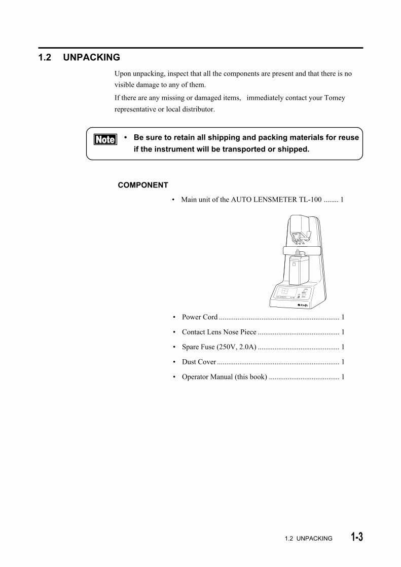
• Main unit of the AUTO LENSMETER TL-100 ........ 1
• Power Cord ................................................................. 1
• Contact Lens Nose Piece ............................................ 1
• Spare Fuse (250V, 2.0A) ............................................ 1
• Dust Cover .................................................................. 1
• Operator Manual (this book) ...................................... 1
HOLD
COMPONENT
1-4 1.3 EXPLANATION OF TERMS
1.3 EXPLANATION OF TERMS
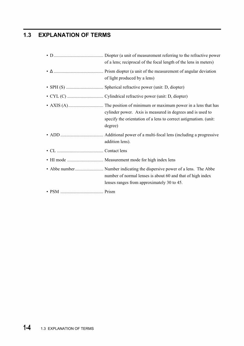
• D............................................ Diopter (a unit of measurement referring to the refractive power
of a lens; reciprocal of the focal length of the lens in meters)
• ∆ ............................................ Prism diopter (a unit of the measurement of angular deviation
of light produced by a lens)
• SPH (S) ................................. Spherical refractive power (unit: D, diopter)
• CYL (C) ................................ Cylindrical refractive power (unit: D, diopter)
• AXIS (A)............................... The position of minimum or maximum power in a lens that has
cylinder power. Axis is measured in degrees and is used to
specify the orientation of a lens to correct astigmatism. (unit:
degree)
• ADD ...................................... Additional power of a multi-focal lens (including a progressive
addition lens).
• CL ......................................... Contact lens
• HI mode ................................ Measurement mode for high index lens
• Abbe number ......................... Number indicating the dispersive power of a lens. The Abbe
number of normal lenses is about 60 and that of high index
lenses ranges from approximately 30 to 45.
• PSM ...................................... Prism
1-51.4 OUTLINE OF OPERATION
1.4 OUTLINE OF OPERATION
The AUTO LENSMETER TL-100 is an instrument for the
automatic measurement of refractive and prism power of
spectacles and contact lenses.
The TL-100 is composed of a built-in optical system, an
electronic processing system, and a mechanical system.
Placing spectacles or contact lenses on the nose piece initiates
automatic measurement. The results are displayed on the LCD.

1-6
( This page is left intentionally blank )
2-12.1 FRONT
2. COMPONENT LIST AND FUNCTIONS
2.1 FRONT
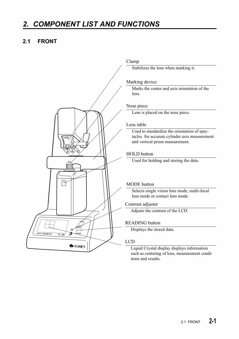
ClampStabilizes the lens when marking it.
Contrast adjusterAdjusts the contrast of the LCD.
READING buttonDisplays the stored data.
LCDLiquid Crystal display displays informationsuch as centering of lens, measurement condi-tions and results.
HOLD
Marking deviceMarks the center and axis orientation of thelens.
Nose pieceLens is placed on the nose piece.
Lens tableUsed to standardize the orientation of spec-tacles for accurate cylinder axis measurementand vertical prism measurement.
HOLD buttonUsed for holding and storing the data.
MODE buttonSelects single vision lens mode, multi-focallens mode or contact lens mode.

2-2
AUTO LENSMETER TL-100 S/N
MANUFACTURER100-240V~ 50/60Hz 35VA
T2A 250V
ON OFF
NAME: TOMEY CORPORATION ADDRESS: 2-11-33 Noritakeshinmachi,
Nishi-ku, Nagoya 451-0051 Japan
2.2 BACK
2.2 BACK
Name plateShows the serial number.
AC power terminalThe accompanying power cord is connected to thisterminal.
Power switchTurns the power on or off.
Fuse holderThe fuse is mounted in this holder.
2-3
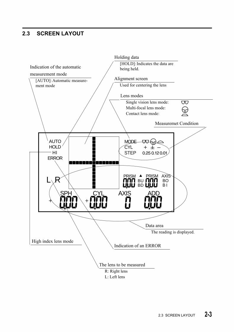
Alignment screenUsed for centering the lens
2.3 SCREEN LAYOUT
2.3 SCREEN LAYOUT
AUTOHOLD
HIERROR
L R
MODECYLSTEP
PRISM PRISM AXISBOB I
BUBD
SPH CYL AXIS ADD
Data areaThe reading is displayed.
Holding data[HOLD]: Indicates the data arebeing held.Indication of the automatic
measurement mode[AUTO]: Automatic measure-ment mode
The lens to be measuredR: Right lensL: Left lens
Indication of an ERROR
Lens modesSingle vision lens mode:Multi-focal lens mode:Contact lens mode:
High index lens mode
Measuremet Condition

2-4
( This page is left intentionally blank )
3-1
3. METHOD OF OPERATION
3.1 Preparation for operating
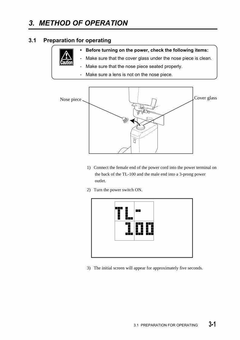
• Before turning on the power, check the following items:
- Make sure that the cover glass under the nose piece is clean.
- Make sure that the nose piece seated properly.
- Make sure a lens is not on the nose piece.
1) Connect the female end of the power cord into the power terminal on
the back of the TL-100 and the male end into a 3-prong power
outlet.
2) Turn the power switch ON.
3) The initial screen will appear for approximately five seconds.
Nose piece Cover glass
3.1 PREPARATION FOR OPERATING
HOLD

3-2
4) The measurement screen will appear.
AUTO MODECYLSTEP
RSPH CYL AXIS ADD
• Do not place a lens onto the nose piece until after the
measurement screen appears.
• Turning the instrument on with the lens already on the
nose piece initiates a beep and indicates "INITIAL ERROR"
on the LCD. Remove the lens from the nose piece, then
press any button to proceed.
ERROR
3.1 PREPARATION FOR OPERATING

3-33.2 MEASURING METHODS
3.2 MEASURING METHODS
3.2.1 MEASURING SINGLE VISION LENSES
If the instrument is not in Single Vision mode ( ), change to
Single Vision mode by pressing the MODE button. Single Vision
mode ( ), Multi-focal mode ( ) and Contact Lens mode ( )
are set consecutively each time the MODE button is pressed.
a) Automatic Hold Mode
In the automatic hold mode, readings are automatically held when
the lens is properly aligned.
• Thrusting a lens onto the nose piece or moving a lens
quickly may result in damage to the lens.
1) If the instrument is in manual hold mode and you wish to use
automatic (AUTO) hold mode, press the HOLD button for
approximately 1 second until "AUTO" appears at the upper left of
the screen.
2) Place the right lens on the nose piece with the bottom of the frame
away from you and the temple downward (as shown below).
HOLD
AUTOHOLD
MODECYLSTEP
RSPH CYL AXIS ADD

3-4
• The right lens must be measured first and then the left lens.
3) Move the lens gently right and left, back and forth to center the
cursor (+) on the crosshair. The reading will be displayed in real
time.
4) When alignment is achieved, a beep will sound and the reading will
be automatically held.
MODECYLSTEP
SPH CYL AXIS ADDR
HOLDAUTO
5) When the right lens is removed from the nose piece, the instrument
is ready to measure the left lens.
6) Place the left lens on the nose piece as described in step 2 and
follow steps 3-4.
• When the left lens is placed on the nose piece, "HOLD" will
disappear from the screen. However, the right lens data will
be retained, and if the Output button is pressed after
measuring the left lens, data for both lenses will be
displayed.
3.2 MEASURING METHODS
3-5
b) Manual Hold Mode
• Thrusting the lens onto the nose piece or moving the lens
quickly may result in damage to the lens.
1) If the instrument is in automatic (AUTO) hold mode and you wish
to change to manual hold mode, press the HOLD button (located
below the nose piece) for approximately 1 second, until "AUTO"
disappears from the display.
2) Place the right lens on the nose piece with the bottom of the frame
away from you and the temples downward (as shown on page 3-3).
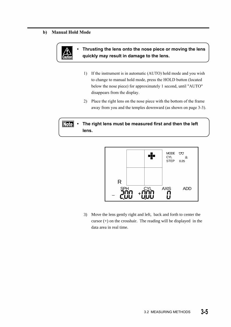
• The right lens must be measured first and then the left
lens.
MODECYLSTEP
SPH CYL AXIS ADD
R
3) Move the lens gently right and left, back and forth to center the
cursor (+) on the crosshair. The reading will be displayed in the
data area in real time.
3.2 MEASURING METHODS
3-6
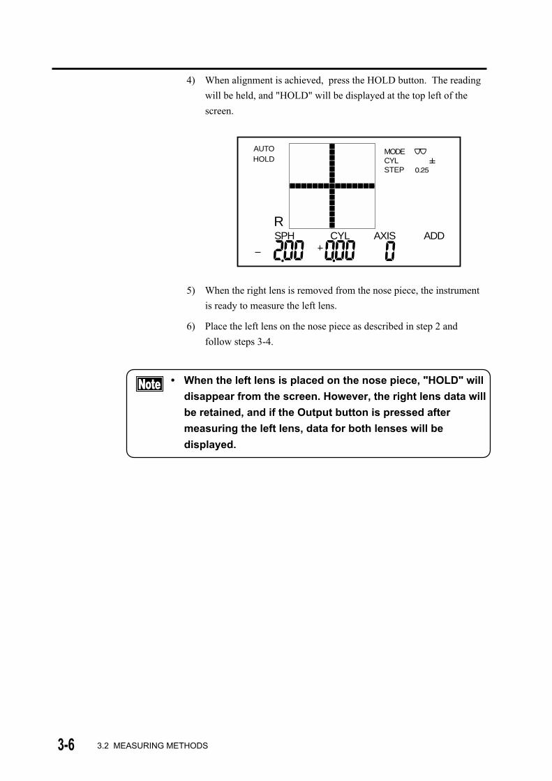
4) When alignment is achieved, press the HOLD button. The reading
will be held, and "HOLD" will be displayed at the top left of the
screen.
MODECYLSTEP
SPH CYL AXIS ADDR
HOLDAUTO
5) When the right lens is removed from the nose piece, the instrument
is ready to measure the left lens.
6) Place the left lens on the nose piece as described in step 2 and
follow steps 3-4.
• When the left lens is placed on the nose piece, "HOLD" will
disappear from the screen. However, the right lens data will
be retained, and if the Output button is pressed after
measuring the left lens, data for both lenses will be
displayed.
3.2 MEASURING METHODS

3-7
3.2.2 MEASURING MULTI-FOCAL LENSES (MULTI-FOCAL MODE)
The MULTI-FOCAL mode is used for measuring both progressive
addition lenses and bi-focal lenses.
• Refer to the Section 5.1 "Troubleshooting guide" for
details of measuring in the MULTI-FOCAL mode.
• In AUTO mode, the add reading is automatically held.
Press the HOLD button for approximately 1 second
without placing a lens on the nose piece to switch the
mode between AUTO and MANUAL.
• Thrusting a lens onto the nose piece or moving a lens
quickly may result in damage to the lens.
a) Measuring Progressive Addition Lenses
1) Change to Multi-Focal mode ( ) by pressing the MODE button.
Single Vision mode ( ), Multi-focal mode ( ), and Contact
Lens mode ( ) are set consecutively each time the MODE button
is pressed.
MODECYLSTEP
RSPH CYL AXIS ADD
AUTO
2) Locate the progressive (near) area.
a. Place the right lens on the nose piece so that the progressive area is
positioned away from you, as illustrated on p.3-3. The progressive
channel normally starts at the middle of the lens (vertically) and
extends downward.
3.2 MEASURING METHODS
3-8
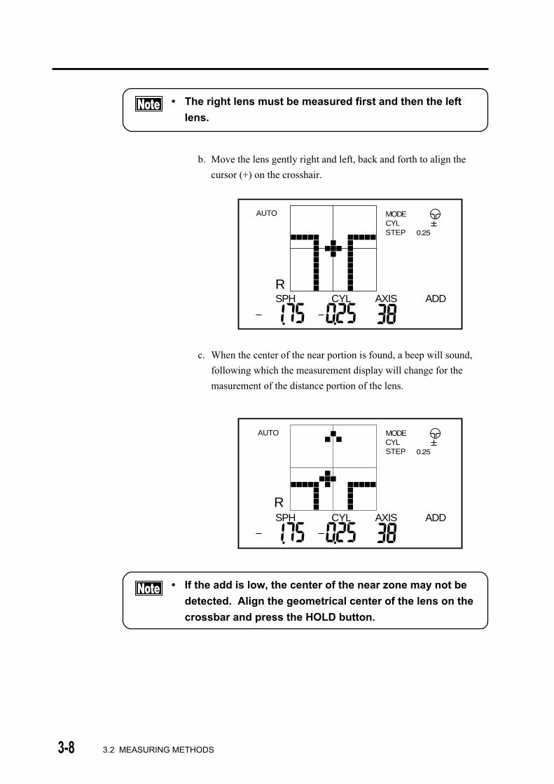
• The right lens must be measured first and then the left
lens.
b. Move the lens gently right and left, back and forth to align the
cursor (+) on the crosshair.
MODECYLSTEP
RSPH CYL AXIS ADD
AUTO
c. When the center of the near portion is found, a beep will sound,
following which the measurement display will change for the
masurement of the distance portion of the lens.
MODECYLSTEP
RSPH CYL AXIS ADD
AUTO
• If the add is low, the center of the near zone may not be
detected. Align the geometrical center of the lens on the
crossbar and press the HOLD button.
3.2 MEASURING METHODS
3-9
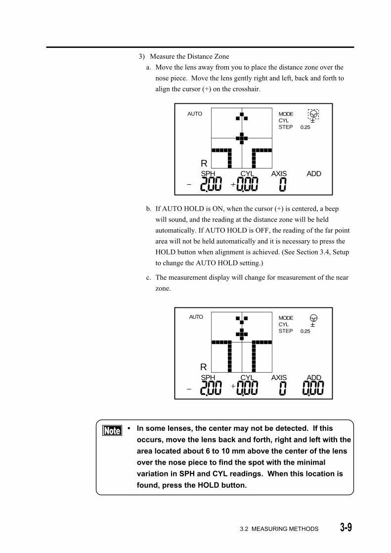
3) Measure the Distance Zone
a. Move the lens away from you to place the distance zone over the
nose piece. Move the lens gently right and left, back and forth to
align the cursor (+) on the crosshair.
AUTO MODECYLSTEP
RSPH CYL AXIS ADD
b. If AUTO HOLD is ON, when the cursor (+) is centered, a beep
will sound, and the reading at the distance zone will be held
automatically. If AUTO HOLD is OFF, the reading of the far point
area will not be held automatically and it is necessary to press the
HOLD button when alignment is achieved. (See Section 3.4, Setup
to change the AUTO HOLD setting.)
c. The measurement display will change for measurement of the near
zone.
MODECYLSTEP
SPH CYL AXIS ADD
AUTO
R
• In some lenses, the center may not be detected. If this
occurs, move the lens back and forth, right and left with the
area located about 6 to 10 mm above the center of the lens
over the nose piece to find the spot with the minimal
variation in SPH and CYL readings. When this location is
found, press the HOLD button.
3.2 MEASURING METHODS
3-10
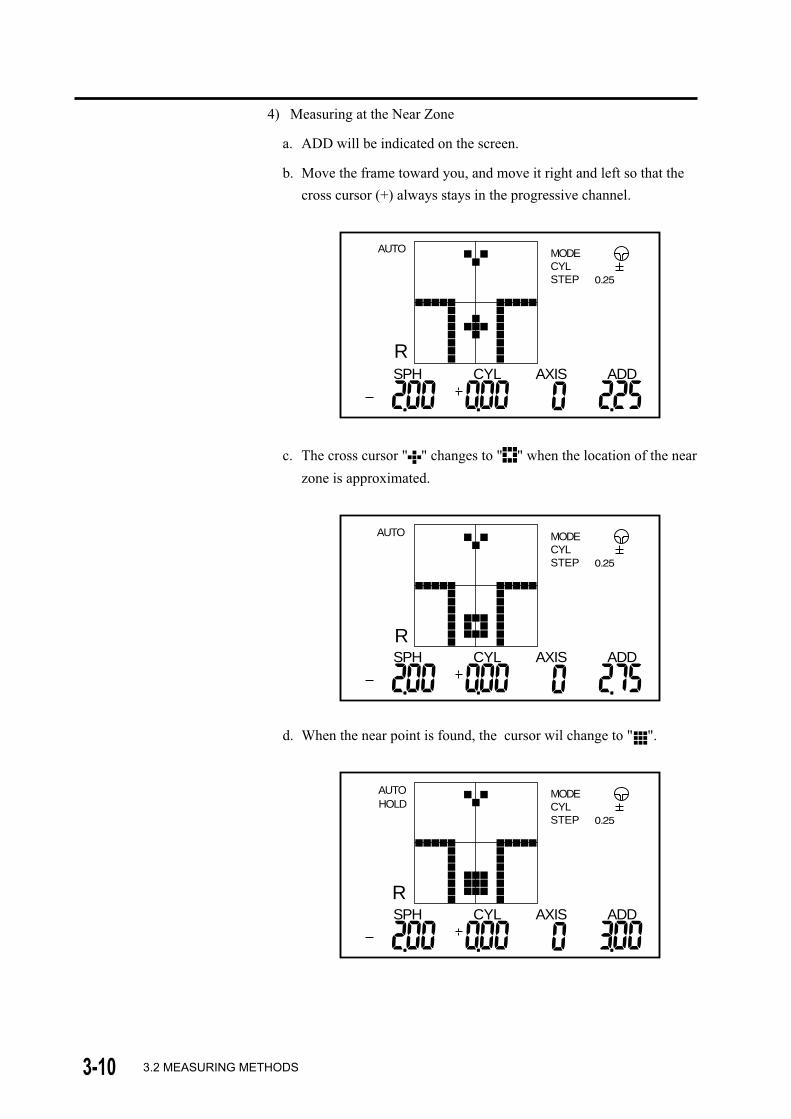
4) Measuring at the Near Zone
a. ADD will be indicated on the screen.
b. Move the frame toward you, and move it right and left so that the
cross cursor (+) always stays in the progressive channel.
MODECYLSTEP
AUTO
RSPH CYL AXIS ADD
c. The cross cursor " " changes to " " when the location of the near
zone is approximated.
MODECYLSTEP
AUTO
RSPH CYL AXIS ADD
d. When the near point is found, the cursor wil change to " ".
MODECYLSTEP
AUTO
RSPH CYL AXIS ADD
HOLD
3.2 MEASURING METHODS

3-11
e. In AUTO mode, a beep will sound, and the ADD reading will be
held automatically. In Manual mode, press the HOLD button.
If the near zone of a progressive addition lens is located very close
to the frame, the cross cursor (+) may not change to " " and then
to " ". In such a case, regard the area with the highest addition
reading in the progressive channel as the near point. Press the
HOLD button manually to store the ADD reading.
5) When the right lens is removed from the nose piece, the instrument is
ready to measure the left lens.
6) Place the left lens on the nose piece as described in step 2a and
follow steps 2b-4.
• When the left lens is placed on the nose piece, "HOLD" will
disappear from the screen. However, the right lens data will
be retained, and if the READING button is pressed after
measuring the left lens, data for both lenses will be
displayed.
3.2 MEASURING METHODS
3-12
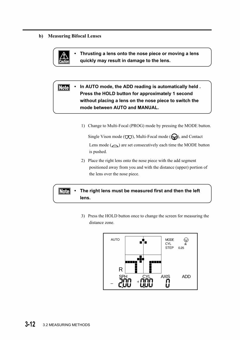
b) Measuring Bifocal Lenses
• Thrusting a lens onto the nose piece or moving a lens
quickly may result in damage to the lens.
• In AUTO mode, the ADD reading is automatically held .
Press the HOLD button for approximately 1 second
without placing a lens on the nose piece to switch the
mode between AUTO and MANUAL.
1) Change to Multi-Focal (PROG) mode by pressing the MODE button.
Single Vison mode ( ), Multi-Focal mode ( ), and Contact
Lens mode ( ) are set consecutively each time the MODE button
is pushed.
2) Place the right lens onto the nose piece with the add segment
positioned away from you and with the distance (upper) portion of
the lens over the nose piece.
• The right lens must be measured first and then the left
lens.
3) Press the HOLD button once to change the screen for measuring the
distance zone.
AUTO MODECYLSTEP
RSPH CYL AXIS ADD
3.2 MEASURING METHODS
3-13
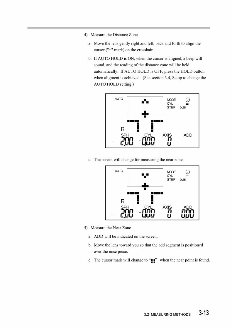
4) Measure the Distance Zone
a. Move the lens gently right and left, back and forth to align the
cursor ("+" mark) on the crosshair.
b. If AUTO HOLD is ON, when the cursor is aligned, a beep will
sound, and the reading of the distance zone will be held
automatically. If AUTO HOLD is OFF, press the HOLD button
when aligment is achieved. (See section 3.4, Setup to change the
AUTO HOLD setting.)
MODECYLSTEP
AUTO
SPH CYL AXIS ADDR
c. The screen will change for measuring the near zone.
MODECYLSTEP
AUTO
SPH CYL AXIS ADDR
5) Measure the Near Zone
a. ADD will be indicated on the screen.
b. Move the lens toward you so that the add segment is positioned
over the nose piece.
c. The cursor mark will change to “ ” when the near point is found.
3.2 MEASURING METHODS

3-14
MODECYLSTEP
AUTO
RSPH CYL AXIS ADD
HOLD
6) When the left lens is removed from the nose piece, the instrument is
ready to measure the left lens.
7) Place the left lens on the nose piece as described in step 2 and follow
steps 3-5.
• When the left lens is placed on the nose piece, "HOLD" will
disappear from the screen. However, the right lens data will
be retained, and if the READING button is pressed after
measuring the left lens, data for both lenses will be
displayed.
3.2 MEASURING METHODS
3-15
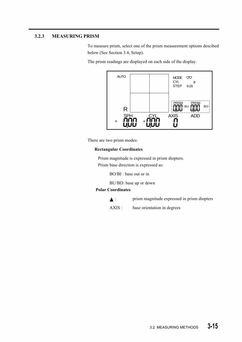
3.2.3 MEASURING PRISM
To measure prism, select one of the prism measurement options descibed
below (See Section 3.4, Setup).
The prism readings are displayed on each side of the display.
There are two prism modes:
Rectangular Coordinates
Prism magnitude is expressed in prism diopters.
Prism base direction is expressed as:
BO/BI : base out or in
BU/BD: base up or down
Polar Coordinates
: prism magnitude expressed in prism diopters
AXIS : base orientation in degrees
3.2 MEASURING METHODS
MODECYLSTEP
AUTO
RPRISM PRISM
BOBU
SPH CYL AXIS ADD

3-16
3.2.4 MEASURING HIGH INDEX LENSES (HI MODE)
• It is reccomended to use the High Index (HI) mode when
measuring high index lenses.
1) The default Abbe value for normal index lenses is 60. When the
instrument is set in HI mode, the default Abbe number is 35. The
Abbe number used for HI mode may be changed, as described in
Section 3.4, Setup.
2) To activate HI mode, press and hold the MODE button for
approximately1 second until "HI" is indicated at the upper left of the
display.
HI
MODECYLSTEP
RSPH CYL AXIS ADD
3) Follow the instructions for measuring lenses in Sections 3.2.1-3.2.3
• To return to Normal Mode, press the MODE button for
approximately 1 second until the "HI" indicator
dissappears.
3.2 MEASURING METHODS

3-17
3.2.5 MEASURING CONTACT LENSES (CL MODE)
• Be sure to use Contact Lens mode (CL mode) when
measuring contact lenses. Measuring in Spectacle mode
may result in errors because the measurement conditions
for contact lenses are different from those for spectacles.
1) Remove the standard nose piece and install the Contact Lens nose
piece.
2) Choose the CL mode by pressing the MODE button. Single Vision
mode ( ), Multi-Focal mode ( ), and Contact Lens mode ( )
are set consecutively each time the MODE button is pressed.
MODECYLSTEP
RSPH CYL AXIS ADD
3.2 MEASURING METHODS
CL
3-18
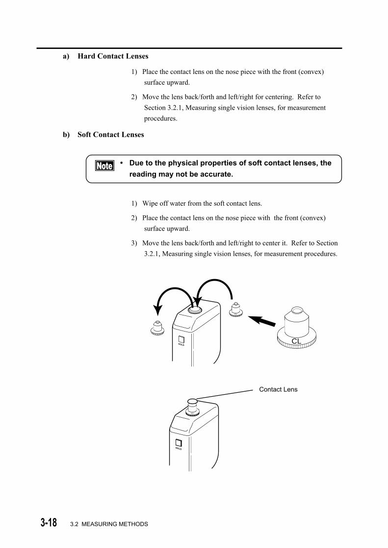
a) Hard Contact Lenses
1) Place the contact lens on the nose piece with the front (convex)
surface upward.
2) Move the lens back/forth and left/right for centering. Refer to
Section 3.2.1, Measuring single vision lenses, for measurement
procedures.
b) Soft Contact Lenses
• Due to the physical properties of soft contact lenses, the
reading may not be accurate.
1) Wipe off water from the soft contact lens.
2) Place the contact lens on the nose piece with the front (convex)
surface upward.
3) Move the lens back/forth and left/right to center it. Refer to Section
3.2.1, Measuring single vision lenses, for measurement procedures.
3.2 MEASURING METHODS
Contact Lens
HOLD
CL
CL
HOLD
CL
3-19
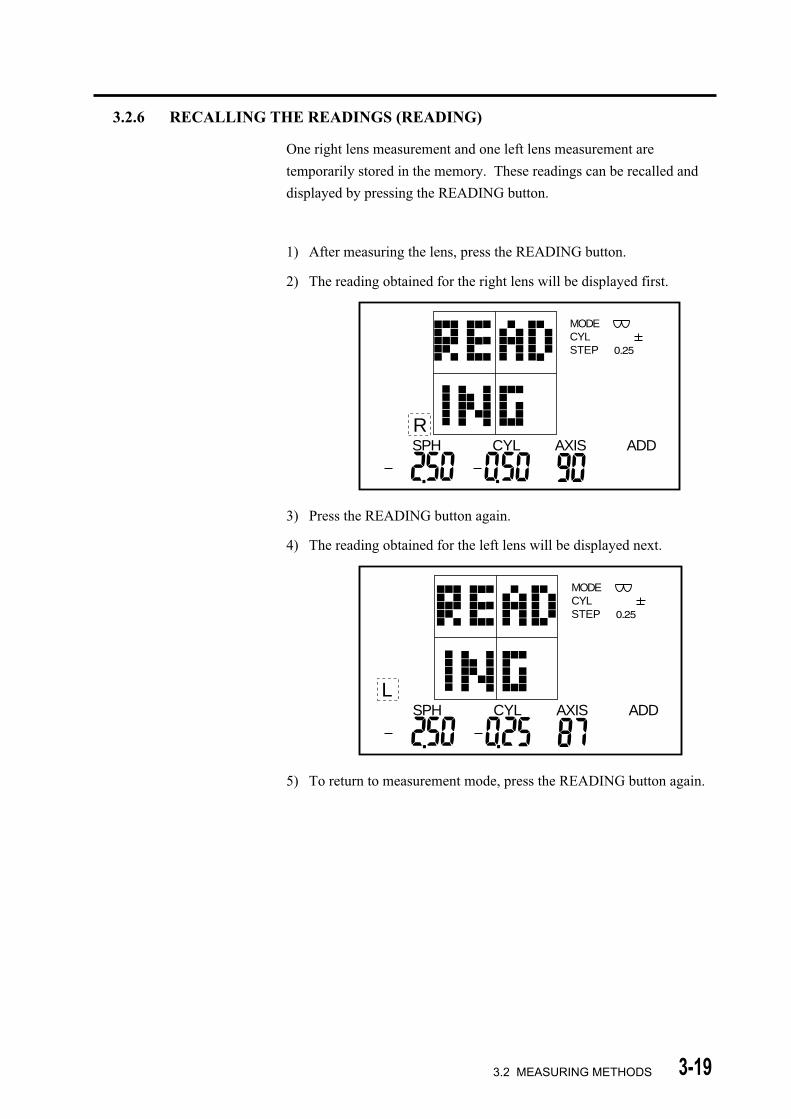
3.2.6 RECALLING THE READINGS (READING)
One right lens measurement and one left lens measurement are
temporarily stored in the memory. These readings can be recalled and
displayed by pressing the READING button.
1) After measuring the lens, press the READING button.
2) The reading obtained for the right lens will be displayed first.
MODECYLSTEP
RSPH CYL AXIS ADD
3) Press the READING button again.
4) The reading obtained for the left lens will be displayed next.
MODECYLSTEP
LSPH CYL AXIS ADD
5) To return to measurement mode, press the READING button again.
3.2 MEASURING METHODS
3-20
• If no readings have been stored, nothing will be displayed
when the READING button is pressed.
• To return to the measurement display, remove the lens
from the nose piece and either place a lens on the nose
piece again or press any button, except the READING
button.
• Previously stored readings will stay in memory until new
readings are stored , either by pushing the HOLD button in
MANUAL mode or automatically in AUTO mode.
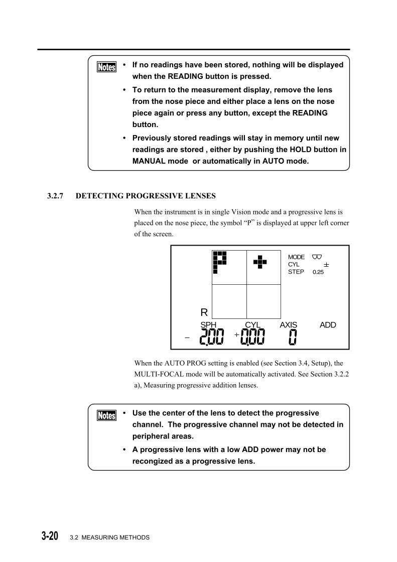
3.2.7 DETECTING PROGRESSIVE LENSES
When the instrument is in single Vision mode and a progressive lens is
placed on the nose piece, the symbol “P” is displayed at upper left corner
of the screen.
MODECYLSTEP
RSPH CYL AXIS ADD
When the AUTO PROG setting is enabled (see Section 3.4, Setup), the
MULTI-FOCAL mode will be automatically activated. See Section 3.2.2
a), Measuring progressive addition lenses.
• Use the center of the lens to detect the progressive
channel. The progressive channel may not be detected in
peripheral areas.
• A progressive lens with a low ADD power may not be
recongized as a progressive lens.
3.2 MEASURING METHODS

3-213.3 OPERATING THE CLAMP, MARKING DEVICE AND LENS TABLE
3.3 OPERATING THE CLAMP, MARKING DEVICE AND LENS TABLE
3.3.1 CLAMP
• Lower the clamp slowly. Quick lowering of the clamp may
result in damage to the lens.
The clamp is used to stabilize the position of the lens when marking it.
(Refer to Section 3.3.2 "Marking device.")
1) Raise the clamp upward with your finger to release the lock.
2) Lower the clamp gently onto the lens.
HOLD

3-22 3.3 OPERATING THE CLAMP, MARKING DEVICE AND LENS TABLE
3.3.2 MARKING DEVICE
The marking device places three marks on the lens, one in the center of the
lens and one approximately 16 mm lateral to the center on each side along
the lens axis.
1) Press and turn the marking lever, causing the pens to descend and mark
the lens surface.
2) Carefully release the marking lever, so it will return to its initial position
by its spring force.
The three (3) marking pens are self-contained cartridges. When the ink
supply becomes depleted, replace the cartridge. (See Section 4.3.2, Ink
cartridge.)
Hold
HOLD

3-233.3 OPERATING THE CLAMP, MARKING DEVICE AND LENS TABLE
3.3.3 LENS TABLE
The lens table serves to standardize the axis of cylindrical lenses and the
height of the frame for measuring vertical prism.
1) Adjust the lens table so that it meets bottom edge of the frame by
pushing or pulling it.
2) The outer diameter of the lens is indicated on the scale on the upper
surface of the nose section.
HOLD
3-24 3.4 SETUP
3.4 SETUP
Indication units and measurement conditions may be selected and modified
in the MENU MODE.
The highlighted menu indicates that it has been selected.
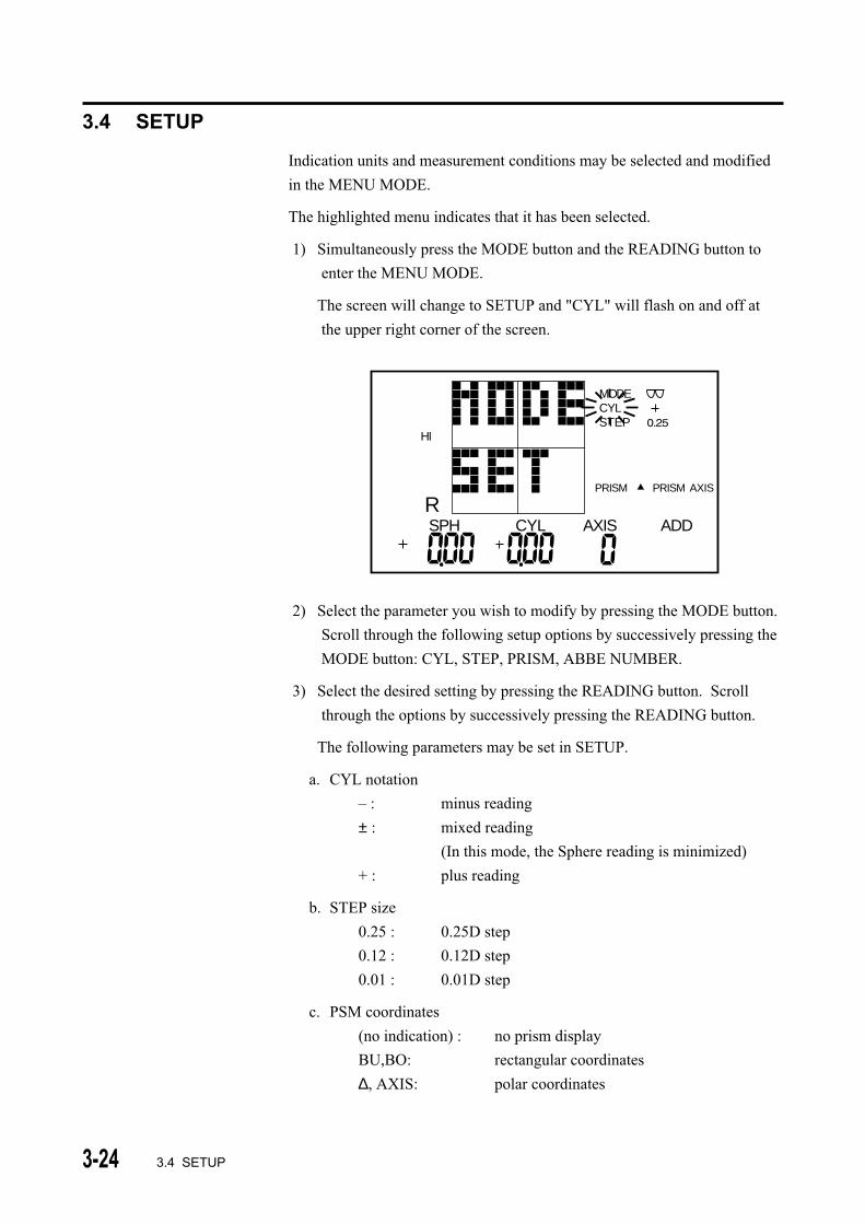
1) Simultaneously press the MODE button and the READING button to
enter the MENU MODE.
The screen will change to SETUP and "CYL" will flash on and off at
the upper right corner of the screen.
2) Select the parameter you wish to modify by pressing the MODE button.
Scroll through the following setup options by successively pressing the
MODE button: CYL, STEP, PRISM, ABBE NUMBER.
3) Select the desired setting by pressing the READING button. Scroll
through the options by successively pressing the READING button.
The following parameters may be set in SETUP.
a. CYL notation
– : minus reading
± : mixed reading
(In this mode, the Sphere reading is minimized)
+ : plus reading
b. STEP size
0.25 : 0.25D step
0.12 : 0.12D step
0.01 : 0.01D step
c. PSM coordinates
(no indication) : no prism display
BU,BO: rectangular coordinates
∆, AXIS: polar coordinates
HI
MODECYLSTEP
RSPH CYL AXIS ADD
PRISM PRISM AXIS
3-253.4 SETUP
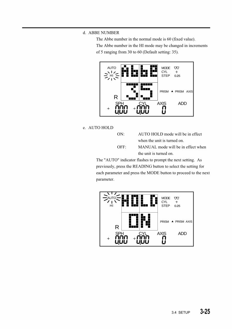
d. ABBE NUMBER
The Abbe number in the normal mode is 60 (fixed value).
The Abbe number in the HI mode may be changed in increments
of 5 ranging from 30 to 60 (Default setting: 35).
AUTO
HI
MODECYLSTEP
RPRISM PRISM AXIS
SPH CYL AXIS ADD
e. AUTO HOLD
ON: AUTO HOLD mode will be in effect
when the unit is turned on.
OFF: MANUAL mode will be in effect when
the unit is turned on.
The "AUTO" indicator flashes to prompt the next setting. As
previously, press the READING button to select the setting for
each parameter and press the MODE button to proceed to the next
parameter.
AUTO
HI
MODECYLSTEP
RPRISM PRISM AXIS
SPH CYL AXIS ADD

3-26 3.4 SETUP
AUTO
HI
MODECYLSTEP
RPRISM PRISM AXIS
SPH CYL AXIS ADD
f. AUTO PROG
ON: Automatic activation of the MULTI-FOCAL mode
when a progressive addition is detected.
OFF: MULTI-FOCAL mode is not automatically activated
when a progressive addition is detected.
AUTO
HI
MODECYLSTEP
RPRISM PRISM AXIS
SPH CYL AXIS ADD
5) Press the HOLD button when setup is complete.
The initial measurement screen appears.

3-27
• All settings are saved in non-volatile memory and will not be
lost when the power is turned off. It is not necessary to set
them every time the unit is turned on.
• To change the settings, repeat the above procedures.
• When in Setup mode, if the instrument is not used for more
than 3 minutes, it automatically returns to Measurement
mode.
3.4 SETUP
3-28
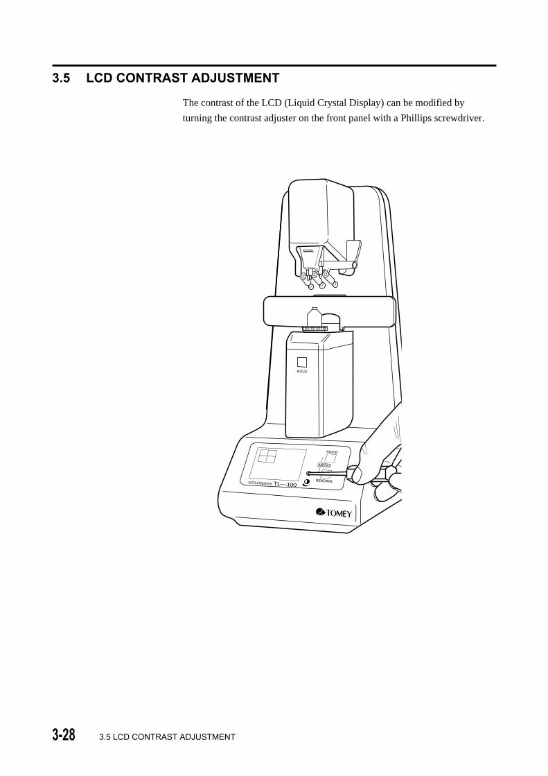
3.5 LCD CONTRAST ADJUSTMENT
The contrast of the LCD (Liquid Crystal Display) can be modified by
turning the contrast adjuster on the front panel with a Phillips screwdriver.
3.5 LCD CONTRAST ADJUSTMENT
HOLD
AUTOLENSMETER TL—100
3-293.6 AUTOMATIC POWER SAVING FUNCTION (AUTO POWER OFF)
3.6 AUTOMATIC POWER SAVING FUNCTION (AUTO POWER OFF)
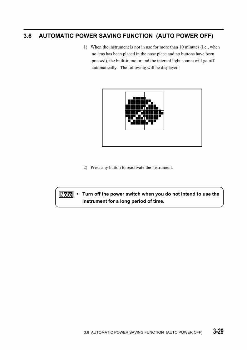
1) When the instrument is not in use for more than 10 minutes (i.e., when
no lens has been placed in the nose piece and no buttons have been
pressed), the built-in motor and the internal light source will go off
automatically. The following will be displayed:
2) Press any button to reactivate the instrument.
• Turn off the power switch when you do not intend to use the
instrument for a long period of time.

3-30
( This page is left intentionally blank )

4-14.1 WARRANTY
4. MAINTENANCE AND INSPECTION
4.1 WARRANTY
One-Year Limited Warranty
The Seller warrants this product to be free from defects in material and
workmanship under the normal use of this product for one year or other term
complying with local regulations from the date of invoice issued by Seller to
the original purchaser.
This warranty shall apply only to the original purchaser and shall not, in any
way, be transferable or assignable to any other party than the original
purchaser.
Lamps, paper and other consumable items shall not be covered by this
warranty.
This warranty also shall NOT apply if the product has not been installed,
operated or maintained in accordance with the OPERATOR MANUAL of
Tomey Corporation (hereinafter called "Tomey"). Neither Seller nor Tomey
shall be liable for any damages caused by purchaser's failure to follow
instructions for proper installation, use and maintenance of the product.
This warranty is only applicable to the new product and DOES NOT cover
any damage resulting from or caused by accident or negligence, abuse,
misuse, mishandling, improper installation, improper repair or improper
modification of this product, by persons other than personnel duly authorized
by Tomey, nor to a product whose serial number or batch number is
removed, altered or effaced.
THIS WARRANTY IS EXPRESSLY IN LIEU OF ANY AND ALL
OTHER WARRANTIES, EXPRESS OR IMPLIED (INCLUDING
SPECIFICALLY, WITHOUT LIMITING THE GENERALITY OF THE
FOREGOING, ALL WARRANTIES OF MERCHANTABILITY AND
FITNESS FOR A PARTICULAR PURPOSE), AND ALL OTHER
OBLIGATION AND LIABILITY ON THE PART OF SELLER AND
TOMEY. NEITHER SELLER NOR TOMEY SHALL BE LIABLE FOR
INCIDENTAL, CONSEQUENTIAL OR SPECIAL DAMAGES UNDER
ANY CIRCUMSTANCES OR FOR MORE THAN REPAIR,
REPLACEMENT OR REFUND OF THE PURCHASE PRICE OF
DEFECTIVE GOODS.

4-2
4.2 ROUTINE MAINTENANCE
• Do not touch the optical elements, such as the cover glass, with your
fingers. Keep them clean. Accuracy of the reading may be adversely
affected by dust or dirt.
• Keep the dust cover over the instrument when the instrument is not in
immediate use.
• Use a dry cloth to clean the cover, screen and the front panel. Use
diluted non-organic detergents for any heavy stains. Do not use organic
solvents, such as thinners, which may cause damage to the surface of
the instrument.
• Disconnect the power cord if you do not plan to use the instrument for a
long time.
4.2.1 CLEANING COVER GLASS
Clean the cover glass periodically.
1) Remove the nose piece.
2) Clean the cover glass as follows:
Remove the dust on the cover glass using a blower (i.e., compressed
air). If the dirt still remains, gently wipe it off using a soft cloth or lens
cleaning accessories.
4.2 ROUTINE MAINTENANCE
• Scratches on the cover glass may result in inaccurate
readings.
4-3
4.3 Replacing spare parts
4.3.1 FUSE
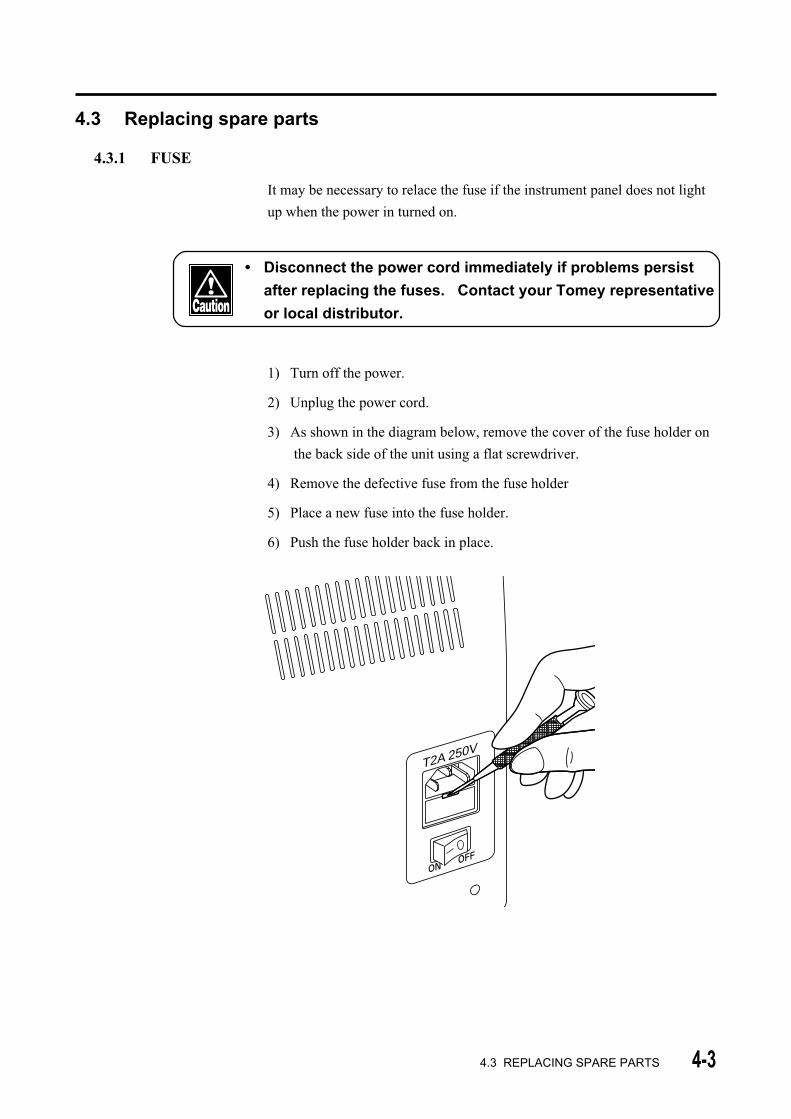
It may be necessary to relace the fuse if the instrument panel does not light
up when the power in turned on.
• Disconnect the power cord immediately if problems persist
after replacing the fuses. Contact your Tomey representative
or local distributor.
1) Turn off the power.
2) Unplug the power cord.
3) As shown in the diagram below, remove the cover of the fuse holder on
the back side of the unit using a flat screwdriver.
4) Remove the defective fuse from the fuse holder
5) Place a new fuse into the fuse holder.
6) Push the fuse holder back in place.
4.3 REPLACING SPARE PARTS
������������������������������������������
@@@@@@@@@@@@@@@@@@@@@@@@@@@@@@@@@@@@@@@@@@
������������������������������������������
ÀÀÀÀÀÀÀÀÀÀÀÀÀÀÀÀÀÀÀÀÀÀÀÀÀÀÀÀÀÀÀÀÀÀÀÀÀÀÀÀÀÀ
������������������������������������������
@@@@@@@@@@@@@@@@@@@@@@@@@@@@@@@@@@@@@@@@@@
������������������������������������������
ÀÀÀÀÀÀÀÀÀÀÀÀÀÀÀÀÀÀÀÀÀÀÀÀÀÀÀÀÀÀÀÀÀÀÀÀÀÀÀÀÀÀ
������������������������������������������
@@@@@@@@@@@@@@@@@@@@@@@@@@@@@@@@@@@@@@@@@@
������������������������������������������
ÀÀÀÀÀÀÀÀÀÀÀÀÀÀÀÀÀÀÀÀÀÀÀÀÀÀÀÀÀÀÀÀÀÀÀÀÀÀÀÀÀÀ
������������������������������������������
@@@@@@@@@@@@@@@@@@@@@@@@@@@@@@@@@@@@@@@@@@
������������������������������������������
ÀÀÀÀÀÀÀÀÀÀÀÀÀÀÀÀÀÀÀÀÀÀÀÀÀÀÀÀÀÀÀÀÀÀÀÀÀÀÀÀÀÀ
������������������������������������������
@@@@@@@@@@@@@@@@@@@@@@@@@@@@@@@@@@@@@@@@@@
������������������������������������������
ÀÀÀÀÀÀÀÀÀÀÀÀÀÀÀÀÀÀÀÀÀÀÀÀÀÀÀÀÀÀÀÀÀÀÀÀÀÀÀÀÀÀ
������������������������������������������
@@@@@@@@@@@@@@@@@@@@@@@@@@@@@@@@@@@@@@@@@@
������������������������������������������
ÀÀÀÀÀÀÀÀÀÀÀÀÀÀÀÀÀÀÀÀÀÀÀÀÀÀÀÀÀÀÀÀÀÀÀÀÀÀÀÀÀÀ
������������������������������������������
@@@@@@@@@@@@@@@@@@@@@@@@@@@@@@@@@@@@@@@@@@
������������������������������������������
ÀÀÀÀÀÀÀÀÀÀÀÀÀÀÀÀÀÀÀÀÀÀÀÀÀÀÀÀÀÀÀÀÀÀÀÀÀÀÀÀÀÀ
������������������������������������������
T2A 250V
4-4
4.3.2 INK CARTRIDGE
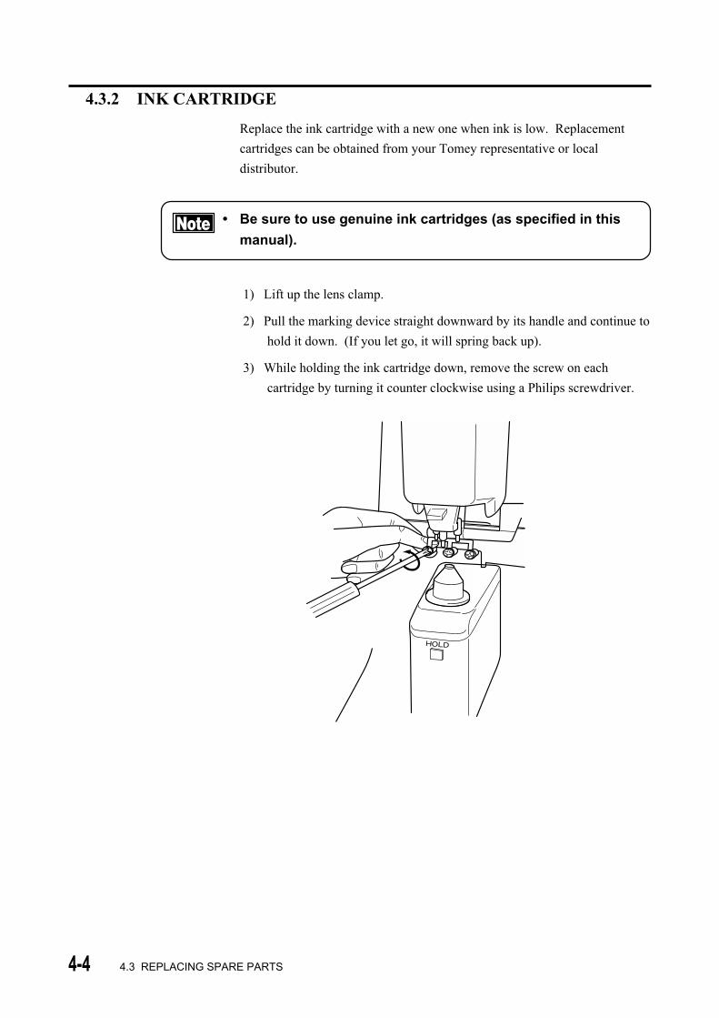
Replace the ink cartridge with a new one when ink is low. Replacement
cartridges can be obtained from your Tomey representative or local
distributor.
• Be sure to use genuine ink cartridges (as specified in this
manual).
1) Lift up the lens clamp.
2) Pull the marking device straight downward by its handle and continue to
hold it down. (If you let go, it will spring back up).
3) While holding the ink cartridge down, remove the screw on each
cartridge by turning it counter clockwise using a Philips screwdriver.
4.3 REPLACING SPARE PARTS
HOLD
4-5
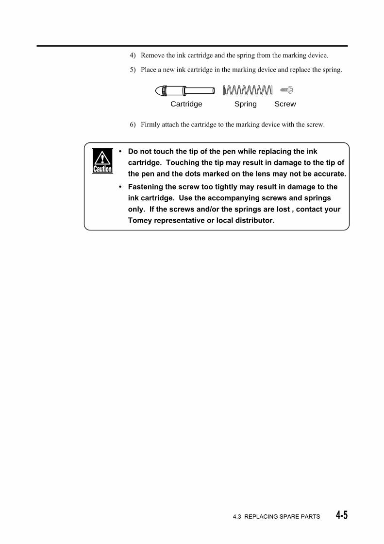
4) Remove the ink cartridge and the spring from the marking device.
5) Place a new ink cartridge in the marking device and replace the spring.
Cartridge Spring Screw
6) Firmly attach the cartridge to the marking device with the screw.
• Do not touch the tip of the pen while replacing the ink
cartridge. Touching the tip may result in damage to the tip of
the pen and the dots marked on the lens may not be accurate.
• Fastening the screw too tightly may result in damage to the
ink cartridge. Use the accompanying screws and springs
only. If the screws and/or the springs are lost , contact your
Tomey representative or local distributor.
4.3 REPLACING SPARE PARTS
4-6
4.4 STORAGE
• Do not store this instrument in a location where it might be
exposed to water.
• Avoid excessive atmospheric pressure, high temperature,
excessive humidity, poor ventilation, direct sunlight, dust,
salt or sulfur in the air.
• Ascertain that factors such as excessive slope, vibration and
impact will not endanger the instrument (including during
transportation).
• Do not store this instrument near chemical substances or in a
location where the gas may be generated.
4.5 PACKING MATERIALS
• Keep the containers and packing materials for future use.
• If you discard the packing materials, be sure to comply with
local ordinances and regulations.
4.4 STORAGE/4.5 PACKING MATERIALS

5-1
5. TROUBLESHOOTING
Before calling service personnel, restart the unit (turn power OFF, then ON)
and check the following.
• Do not attempt measures other than those described below.
• If the problems persist after checking the following, stop
using the unit and immediately contact your Tomey
representative for inspection or repair.
5.1 TROUBLESHOOTING GUIDE
5.1.1 GENERAL OPERATION
1) The LCD does not Light Up After Turning ON.
Cause 1: Failure in connecting the power cord.
Action: Insert the female end of the power cord securely into the
AC power terminal of the instrument.
Insert the male end of the power cord securely into an AC
outlet.
Cause 2: The fuse is blown.
Action: Replace with a new fuse (See Section 4.3.1, Fuse)
Cause 3: Improper adjustment of the screen contrast.
Action: Adjust the contrast of the screen properly by using the
contrast adjuster on the lower right of the operation panel
( See Section 3.5, Controlling the LCD contrast).
2) Freezes at the Initial Screen.
Cause 1: There was an object on the nose piece when the instrument was
turned ON.
Action: Remove the object from the nose piece and press any
button.
Cause 2: The nose piece is not seated properly.
Action: Seat the nose piece properly and press any button.
5.1 TROUBLESHOOTING GUIDE
5-2 5.1 Troubleshooting guide
Cause 3: The cover glass under the nose piece is not clean.
Action: Turn off the power. Remove the nose piece and then
clean the cover glass (See Section 4.2.1, Cleaning cover
glass). Replace the nose piece and turn the power on
again.
3) "INITIAL ERR!" is Displayed.
Cause 1: A lens was on the nose piece when the power was turned on.
Action: Remove the lens and press any button.
Cause 2: The nose piece is not seated properly.
Action: Seat the nose piece properly and press any button.
Cause 3: The cover glass under the nose piece is not clean.
Action: Turn off the power. Remove the nose piece and clean the
cover glass (see Section 4.2.1, Cleaning cover glass).
Replace the nose piece and turn the power on again.
4) a) The Sph, Cyl or Axis value is not ZERO (0.00) with No Lens on the Nose Piece.
b) The Readings are Inaccurate.
Cause 1: The nose piece is not seated properly.
Action: Seat the nose piece properly.
Cause 2: The cover glass under the nose piece is not clean.
Action: Turn off the power. Remove the nose piece and clean the
cover glass (See Section 4.2.1, Cleaning cover glass).
Replace the nose piece and turn the power on again.
5-35.1 TROUBLESHOOTING GUIDE
5.1.2 Progressive Addition Lens Measurement
1) The Cursor Cannot be Centered in the Progressive Channel.
Cause 1: With progressive lenses which have a small power difference
between the far point area and the near point area, aligning the
cursor to the center may not be achievable.
Action : The beginning of the progressive channel is located in
approximately the center of the lens or the center of the
frame. Take measurement around that position and press
the HOLD button.
2) The Cursor Cannot be Centered in the Far Point Area.
Cause 1: Progressive lenses are sometimes dispensed for intermediate
and near correction only. In such lenses, the progressive area
extends into the far point area and it is difficult to accurately
measure the far point area.
Action: Take a reading near the top of lens.
Slightly move the lens back and forth, right and left, near
the central top portion of the lens. Regard the area where
the SPH value varies the least as the measurement of the
far point area. Press the HOLD button when this location
is found.
3) The Near Point Area is not Detected. (The Cursor does not Change to " " or
" ".)
Cause 1: The near point area is NOT automatically detected if the ADD
power is less than 1.0 diopter.
Action: Press the HOLD button when judging the highest
addition value when the cursor is in the progressive zone.
Cause 2: The near point area in frame lenses with a long progressive
zone may be positioned very near the edge of the frame or even
outside of the frame. It may not be possible to detect the near
point in such lenses.
Action: Press the HOLD button when judging the highest
addition value when the cursor is in the progressive zone.

5-4 5.1 TROUBLESHOOTING GUIDE
Cause 3: The near point area in a small frame lens may be positioned
very near to the edge of the frame or even outside of the frame.
It may not be possible to detect the near point area in such lenses.
Action: Press HOLD button when judging the highest addition
value when the cursor is in the progressive zone.
4) The ADD Readings are Significantly Lower (> 0.5 diopters) than the Nominal
Values.
Cause 1: The far point area was not measured properly.
Action : With some lenses, the far point area may not be measured
accurately if AUTO HOLD mode is used. Disable the
AUTO HOLD mode in Setup (See Section 3.4, Setup
Menu 3), and measure the far point area manually. If it is
still difficult to measure, slightly move the lens back and
forth, right and left to measure the portion where
variation of SPH readings is minimum and press the
HOLD button.
Measurement Position of the Far Point Area
6 ~ 10mm
Fitting cross
Near power circle
Distance power circle
lens table
6 ~ 10mm
Center of the frame
Distance power circle
lens table
Single Lens Spectacle Lens
5-55.1 TROUBLESHOOTING GUIDE
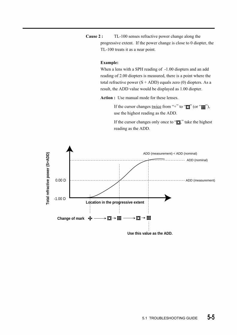
Cause 2 : TL-100 senses refractive power change along the
progressive extent. If the power change is close to 0 diopter, the
TL-100 treats it as a near point.
Example:
When a lens with a SPH reading of -1.00 diopters and an add
reading of 2.00 diopters is measured, there is a point where the
total refractive power (S + ADD) equals zero (0) diopters. As a
result, the ADD value would be displayed as 1.00 diopter.
Action : Use manual mode for these lenses.
If the cursor changes twice from “+” to “ ” (or “ ”),
use the highest reading as the ADD.
If the cursor changes only once to “ ,” take the highest
reading as the ADD.
ADD (nominal)
ADD (measurement)
ADD (measurement) < ADD (nominal)
-1.00 D
0.00 D
Tota
l ref
ract
ive
pow
er (S
+AD
D)
Location in the progressive extent
Change of mark
Use this value as the ADD.

5-6
5) The ADD Readings are Higher than the Nominal Value.
Cause: Some progressive lenses may have a peak of ADD below the
near power circle. With these lenses, the ADD readings may be
higher than the nominal values.
Action: The ADD reading should be taken at the near point
marked on the lens blank. (The cursor may not change to
" ".)
After dispensing, marking do not exist. Read the ADD at
a spot located 20 mm below the center of the frame. (See
diagram below.) Note that in small frames, this location
may be beyond the extent of the frame.
In either case, make sure to take the ADD reading while
the cursor stays in the progressive zone.
The Measurement Position of the Near Point
about 20mm
Center of the frame (Fitting cross)
measurement position ofnear point
lens table
5.1 TROUBLESHOOTING GUIDE
Near power circle
Peak of ADD
Distance power circle
ADD (nominal)
ADD (measurement)
ADD (measurement) > ADD (nominal)
Power
Location
�
5-7
5.2 Error Messages
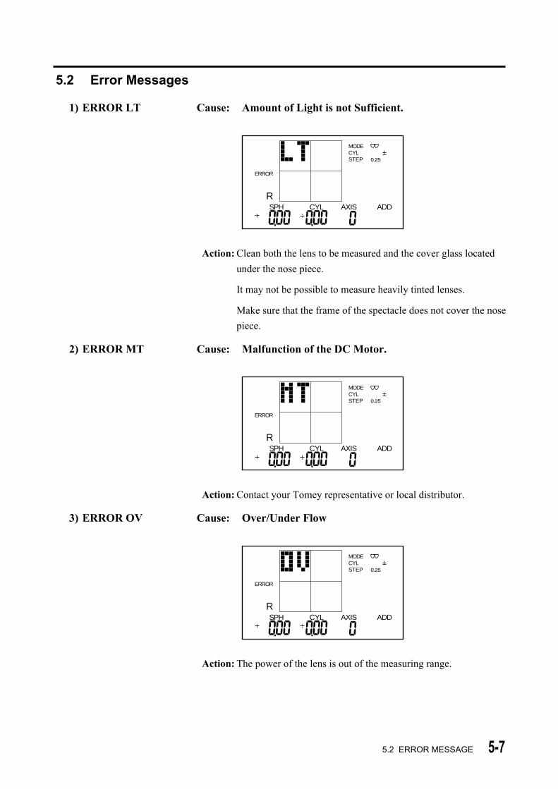
1) ERROR LT Cause: Amount of Light is not Sufficient.
ERROR
MODECYLSTEP
RSPH CYL AXIS ADD
Action: Clean both the lens to be measured and the cover glass located
under the nose piece.
It may not be possible to measure heavily tinted lenses.
Make sure that the frame of the spectacle does not cover the nose
piece.
2) ERROR MT Cause: Malfunction of the DC Motor.
ERROR
MODECYLSTEP
RSPH CYL AXIS ADD
Action: Contact your Tomey representative or local distributor.
3) ERROR OV Cause: Over/Under Flow
ERROR
MODECYLSTEP
RSPH CYL AXIS ADD
Action: The power of the lens is out of the measuring range.
5.2 ERROR MESSAGE

5-8
4) ERROR INIT ERR
ERROR
Action:
1. Remove the lens from the nose piece, and press any button.
2. Make sure the nose piece is seated properly and press any button.
3. Clean the cover glass located under the nose piece and press any
button.
5.2 ERROR MESSAGE
6-1
6. SPARE PARTS
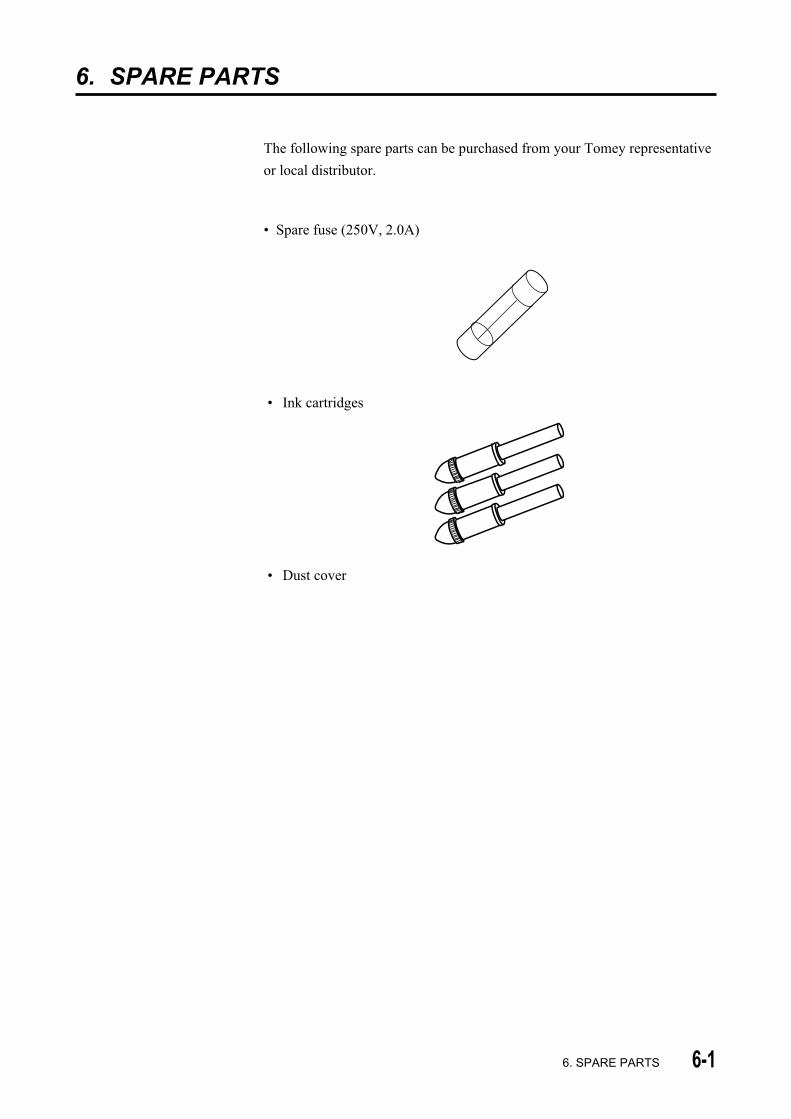
The following spare parts can be purchased from your Tomey representative
or local distributor.
• Spare fuse (250V, 2.0A)
• Ink cartridges
• Dust cover
6. SPARE PARTS

6-2
( This page is left intentionally blank )

7-17. SPECIFICATIONS
7. SPECIFICATIONS
7.1 MEASUREMENT
• Range
Spherical power (S reading): ± 25D
Cylindrical power (C reading): ±9.99D
Axis of cylindrical power (A reading): 0 to 180 degrees
Addition reading (ADD reading): 0 to 9.99 D
Prism power (P reading): 0 to 9.99 ƥ Steps
Power: 0.01/0.12/0.25 D
Prism: 0.01/0.12/0.25 ƥ Modes
Cylinder: + / ± / –
Prism: Rectangular/Polar coordinates
• Sampling speed: 0.035 seconds
• Measurement wavelength: 660 nm
Diameter of the beam: 3 mm
• Lens diameter: 20 to 100 mm
• Lens types: Spectacles, soft and hard contact
lenses
• Abbe numbers: 30 to 60 (5-unit increment)
(30,35,40,45,50,55,60)
7.2 DATA CONTROL
• Display: Two dimensional LCD display with
back light
(character type)
• Alignment: Cross cursor
(Thickens when lens is aligned)
7.3 PHYSICAL DIMENSIONS AND ELECTRICAL REQUIREMENTS
• Dimensions: 200 (W) x 260 (D) x 436 (H) mm
[7.9 (W) x 10.2 (D) x 17.2 (H) in]
• Weight: approx. 5.0 Kg (11.0 lbs)
• Main supply voltage: 100 to 240 V AC
(automatically adjusted)
• Power consumption: 35 VA
• Frequency: 50/60 Hz

7-2
7.4 ENVIRONMENTAL CONDITIONS
• Installation site: indoors
• Operating temperature range: +10°C to + 40°C (+50 °F to +104°F)
maximum relative humidity 80% for
temperatures up to 31°C decreasing
linearly to 50% relative humidity at
40°C
• Main supply voltage fluctuations: ±10% of the normal voltage
• Installation Category: II
• Pollution degree: 2 (based on IEC664)
7.5 APPROVED INTERNATIONAL STANDARDS
• Electrical safety: IEC -1010-1; +A1; +A2
• Electromagnetic compatibility: EN61326IEC61000-3-2IEC61000-3-3
FCC (Part 15 Class B)
7. SPECIFICATIONS

8-18. INDEX
8. INDEXA
Abbe number 1-4, 3-16, 3-25
AC power terminal 2-2
ADD 1-4, 3-10, 3-13, 5-4, 5-5
Alignment screen 2-3
Approved international standards 7-2
AUTO POWER OFF 3-31
Automatic hold mode 3-3, 3-7, 3-12, 3-25
Automatic power saving function 3-29
AUTO HOLD 3-9, 3-13, 3-25, 3-26, 5-4
AUTO PROG 3-20, 3-26
AXIS (A) 1-4
BBifocal lenses 3-12
CCautionary notes 1-1
CL 1-4
CL mode 3-17
Clamp 2-1, 3-21
Components 1-3
Contact lenses 3-17
Contrast adjuster 2-1, 3-28, 5-1
Controlling the LCD contrast 3-30
Cover glass 4-2, 5-1, 5-2, 5-7
Cross 3-5, 7-1, 3-11
CYL (C) 1-4, 3-24
DD 1-4
Data control 7-1
Detecting progressive lenses 3-20, 3-26
Dimensions 7-1
Distance zone 3-9, 3-13
EElectrical requirements 7-1
Environmental conditions 7-2
ERROR INIT ERR 5-9
ERROR LT 5-8
Error messages 5-7
ERROR MT 5-8
ERROR OV 5-8
ERROR PR 5-9
Explanation of terms 1-4
External output terminal (RS-232C) 2-1
FFar point area 3-9, 3-13, 5-3, 5-4
Fuse 4-3, 5-1, 6-1
Fuse holder 2-2, 4-3
HHard contact lenses 3-18
HI 1-4, 3-16
High Index lenses 3-16, 3-25
HOLD button 2-1, 3-6, 3-25
IInitial display screen 3-1, 5-1
INITIAL ERR! 3-2, 5-2, 5-8
Ink cartridge 4-4, 6-1
International standards 7-2
LLCD 2-1, 5-1
LCD contrast 3-28, 5-1
Lens modes 2-3
Lens table 2-1, 3-23
Lever 2-1
MMAINTENANCE 4-1
Manual hold mode 3-5
Marking device 2-1, 3-22
Measuring bifocal lenses 3-12
Measuring contact lenses 3-17
Measuring high index lenses 3-16
Measuring methods 3-3
Measuring multi-focal lenses 3-7
Measuring prism 3-15
Measuring progressive addition lenses 3-7
Measuring single vision lenses 3-3
MODE button 2-1, 3-3, 3-7, 3-12, 3-17, 3-24
Multi-focal lenses 3-7
Multi-focal mode 3-7, 3-12, 3-20
NNear point area / near zone 3-7, 3-10, 3-13, 5-3
Nose piece 2-1, 3-1, 5-1, 5-2
OOne-Year Limited Warranty 4-1
OUTPUT button 2-1, 3-4, 3-6, 3-11, 3-14, 3-19, 3-28
OUTPUT 3-19, 3-24

8-2 8. INDEX
PPacking materials 4-6
Power cord 3-1, 5-1
Power saving function 3-29
Power switch 2-2, 3-1
Progressive addition lenses 3-7
Polar coordinates 3-15, 3-25
Prism 3-15, 3-25
PSM 1-4, 3-25
RREADING button 2-1, 3-4, 3-6, 3-11, 3-14, 3-19,
3-20
READING 3-19, 3-24, 3-25
Recalling the readings 3-19
Rectangular coordinates 3-15, 3-25
Replacing spare parts 4-3
Routine maintenance 4-2
SScreen layout 2-3
SETUP 3-24
Single vision lenses 3-3
Soft contact lenses 3-18
Spare parts 4-3
SPECIFICATIONS 7-1
SPH (S) 1-4
STEP size (measurement unit) 3-24
Storage 4-6
TTroubleshooting guide 5-1
UUnpacking 1-3
WWarranty 4-1
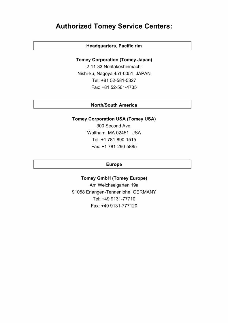
Authorized Tomey Service Centers:
Headquarters, Pacific rim
Tomey Corporation (Tomey Japan)
2-11-33 Noritakeshinmachi
Nishi-ku, Nagoya 451-0051 JAPAN
Tel: +81 52-581-5327
Fax: +81 52-561-4735
North/South America
Tomey Corporation USA (Tomey USA)
300 Second Ave.
Waltham, MA 02451 USA
Tel: +1 781-890-1515
Fax: +1 781-290-5885
Europe
Tomey GmbH (Tomey Europe)
Am Weichselgarten 19a
91058 Erlangen-Tennenlohe GERMANY
Tel: +49 9131-77710
Fax: +49 9131-777120

ID: 0208